EP3377288B1 - Verfahren zur herstellung eines kunststoffgranulats - Google Patents
Verfahren zur herstellung eines kunststoffgranulats Download PDFInfo
- Publication number
- EP3377288B1 EP3377288B1 EP16790290.7A EP16790290A EP3377288B1 EP 3377288 B1 EP3377288 B1 EP 3377288B1 EP 16790290 A EP16790290 A EP 16790290A EP 3377288 B1 EP3377288 B1 EP 3377288B1
- Authority
- EP
- European Patent Office
- Prior art keywords
- plastic granules
- dealdehydization
- pressure
- plastic
- gas
- Prior art date
- Legal status (The legal status is an assumption and is not a legal conclusion. Google has not performed a legal analysis and makes no representation as to the accuracy of the status listed.)
- Active
Links
Images

Classifications
-
- B—PERFORMING OPERATIONS; TRANSPORTING
- B29—WORKING OF PLASTICS; WORKING OF SUBSTANCES IN A PLASTIC STATE IN GENERAL
- B29B—PREPARATION OR PRETREATMENT OF THE MATERIAL TO BE SHAPED; MAKING GRANULES OR PREFORMS; RECOVERY OF PLASTICS OR OTHER CONSTITUENTS OF WASTE MATERIAL CONTAINING PLASTICS
- B29B9/00—Making granules
- B29B9/02—Making granules by dividing preformed material
- B29B9/06—Making granules by dividing preformed material in the form of filamentary material, e.g. combined with extrusion
- B29B9/065—Making granules by dividing preformed material in the form of filamentary material, e.g. combined with extrusion under-water, e.g. underwater pelletizers
-
- B—PERFORMING OPERATIONS; TRANSPORTING
- B01—PHYSICAL OR CHEMICAL PROCESSES OR APPARATUS IN GENERAL
- B01J—CHEMICAL OR PHYSICAL PROCESSES, e.g. CATALYSIS OR COLLOID CHEMISTRY; THEIR RELEVANT APPARATUS
- B01J2/00—Processes or devices for granulating materials, e.g. fertilisers in general; Rendering particulate materials free flowing in general, e.g. making them hydrophobic
- B01J2/20—Processes or devices for granulating materials, e.g. fertilisers in general; Rendering particulate materials free flowing in general, e.g. making them hydrophobic by expressing the material, e.g. through sieves and fragmenting the extruded length
-
- C—CHEMISTRY; METALLURGY
- C08—ORGANIC MACROMOLECULAR COMPOUNDS; THEIR PREPARATION OR CHEMICAL WORKING-UP; COMPOSITIONS BASED THEREON
- C08G—MACROMOLECULAR COMPOUNDS OBTAINED OTHERWISE THAN BY REACTIONS ONLY INVOLVING UNSATURATED CARBON-TO-CARBON BONDS
- C08G63/00—Macromolecular compounds obtained by reactions forming a carboxylic ester link in the main chain of the macromolecule
- C08G63/78—Preparation processes
-
- F—MECHANICAL ENGINEERING; LIGHTING; HEATING; WEAPONS; BLASTING
- F26—DRYING
- F26B—DRYING SOLID MATERIALS OR OBJECTS BY REMOVING LIQUID THEREFROM
- F26B5/00—Drying solid materials or objects by processes not involving the application of heat
- F26B5/16—Drying solid materials or objects by processes not involving the application of heat by contact with sorbent bodies, e.g. absorbent mould; by admixture with sorbent materials
-
- B—PERFORMING OPERATIONS; TRANSPORTING
- B29—WORKING OF PLASTICS; WORKING OF SUBSTANCES IN A PLASTIC STATE IN GENERAL
- B29B—PREPARATION OR PRETREATMENT OF THE MATERIAL TO BE SHAPED; MAKING GRANULES OR PREFORMS; RECOVERY OF PLASTICS OR OTHER CONSTITUENTS OF WASTE MATERIAL CONTAINING PLASTICS
- B29B9/00—Making granules
- B29B9/16—Auxiliary treatment of granules
- B29B2009/165—Crystallizing granules
-
- B—PERFORMING OPERATIONS; TRANSPORTING
- B29—WORKING OF PLASTICS; WORKING OF SUBSTANCES IN A PLASTIC STATE IN GENERAL
- B29B—PREPARATION OR PRETREATMENT OF THE MATERIAL TO BE SHAPED; MAKING GRANULES OR PREFORMS; RECOVERY OF PLASTICS OR OTHER CONSTITUENTS OF WASTE MATERIAL CONTAINING PLASTICS
- B29B9/00—Making granules
- B29B9/16—Auxiliary treatment of granules
- B29B2009/168—Removing undesirable residual components, e.g. solvents, unreacted monomers; Degassing
-
- F—MECHANICAL ENGINEERING; LIGHTING; HEATING; WEAPONS; BLASTING
- F26—DRYING
- F26B—DRYING SOLID MATERIALS OR OBJECTS BY REMOVING LIQUID THEREFROM
- F26B2200/00—Drying processes and machines for solid materials characterised by the specific requirements of the drying goods
- F26B2200/08—Granular materials
-
- F—MECHANICAL ENGINEERING; LIGHTING; HEATING; WEAPONS; BLASTING
- F26—DRYING
- F26B—DRYING SOLID MATERIALS OR OBJECTS BY REMOVING LIQUID THEREFROM
- F26B2200/00—Drying processes and machines for solid materials characterised by the specific requirements of the drying goods
- F26B2200/12—Manure
Definitions
- the invention relates to a method for producing a plastic granulate according to the type specified in the preamble of claim 1.
- DE 10 2007 040 135 A1 relates to a process for the continuous production of polyester granules from highly viscous polyester melts with a degree of polymerization of 132 to 165.
- the highly viscous melt (hiV) is heated by means of a metering pump, which can build up a pressure of> 80 bar to 200 bar
- Nozzle plate 3 pressed underwater pelletizing under at least 1 bar overpressure with a water inlet temperature of at least 70 ° C, preferably 80-95 ° C).
- a closely fitting cutting knife ring peels off the melt from every hole in the nozzle plate, whereby round or oval grains (pellets) are formed, which solidify amorphously on the surface due to intensive water washing.
- the water chamber is under slight overpressure and the liquor ratio is between 8 and 12: 1.
- the pellet / water mixture passes through a short pipe and an agglomerate separator into the pre-dryer, which is designed as a stirred centrifuge, the water separation taking place in the lower area and the pellets exiting in the upper area.
- EP 2 712 881 A1 discloses an apparatus for continuously pelletizing and crystallizing a polymer comprising a unit for forming a polymer pellet material and a cooling pellet material in a liquid cooling medium. A downstream unit for drying pellet material and a crystallizer for crystallizing pellet material are also provided. The crystallizer communicates directly via the connecting line with the upstream unit for separating the liquid cooling medium from the pellet material and drying the pellet material, so that the material to be treated can pass freely from the upstream unit to the subsequent unit. An inlet is used to import inert gas.
- An apparatus for continuously pelletizing and crystallizing a polymer comprises: a unit for forming one Polymer pellet material and for cooling the pellet material in a liquid cooling medium; a downstream unit for drying the pellet material, the downstream unit having an outlet opening for exporting gas; and a crystallizer for crystallizing the pellet material.
- the crystallizer communicates directly via a connecting line with the pre-connected unit for separating the liquid cooling medium from the pellet material and for drying the pellet material, so that the material to be treated can pass unhindered from the pre-connected unit to the downstream unit; and includes an inlet for introducing inert gas, the crystallizer communicating with an inert gas tank via the inlet so that the pressure in the crystallizer can be increased relative to a pressure in the unit for drying the pellet material.
- plastic granules with a high softening temperature, namely above 120 ° C.
- plastic granules can be polycarbonate, polycarbonate blend, polystyrene, high-temperature thermoplastics.
- a process fluid is contained in a process chamber.
- the process chamber is partially delimited by a perforated plate for the production of strands from liquid plastic.
- a dividing device interacts with the perforated plate for the plastic strands emerging from the perforated plate. This creates a mixture of process fluid and granulate.
- the process fluid has a temperature of more than 120 ° C.
- the pressure in the process chamber is greater than 2 bar.
- the mixture of process fluid and granulate passes through a cooling section while maintaining the pressure.
- the granules are then separated from the process fluid under pressure in a separating device and passed through a pressure lock. This procedure has generally proven itself. However, the quality of the plastic granules for further processing for certain applications is still too low.
- the low-water plastic granules obtained in this way after the water has been separated off are placed in a dealdehydization tank and treated there by means of a purge air stream with an inlet temperature between 180 ° C. and 200 ° C.
- the plastic granulate is either directly in the Given dealdehydization container or by means of a metering device. This is intended to simplify the method in terms of apparatus and to operate it at lower operating costs.
- the particularly high quality demands on the polyester for packaging with regard to viscosity, color, acetaldehyde content, acetaldehyde reformation and melting behavior are to be maintained or improved.
- a disadvantage of this method is that the quality of the plastic granulate is not satisfactory for certain applications.
- the object of the invention is therefore to provide a method for producing plastic granules which produce plastic granules with a higher quality with regard to viscosity, color, acetaldehyde content, melting behavior and the like.
- the outlay on equipment should be kept as low as possible and the method should be operated with the lowest possible operating costs.
- the invention is based on the knowledge that both the process parameters in the plastic granulation, which are responsible for the nucleation to influence the crystallization, and for the crystallization as such, but also a dealdehydization of the plastic granules significantly influence the quality of the plastic granules and therefore both measures combined with adapted and coordinated parameters lead to better quality of the plastic granules overall. In addition, this results in further possibilities to optimize the process with regard to operating costs and to improve the quality of the plastic granules.
- a method for producing a plastic granulate in which a process fluid is contained in a process chamber. Underwater pelletizing takes place in the process chamber.
- the process fluid in the process chamber has a temperature that is in a temperature range from greater than or equal to 120 ° C. to a maximum of 160 ° C.
- there is a process pressure in the process chamber that is greater than the pressure of the vapor pressure curve of the process fluid (12), but at least 2.0 bar. Under this process pressure, the plastic strands are granulated into plastic granules.
- a mixture of process fluid and plastic granulate is then discharged from the process chamber with cooling of the plastic granulate into a first cooling section, wherein i the plastic granulate under process pressure from the Process fluid is separated.
- the plastic granulate is then continuously fed in line to a dealdehydization tank.
- the process pressure is maintained and targeted nucleation, i.e. the generation of crystallization nuclei, on the surface of the plastic granulate is made possible by an optimized cooling temperature, so that the plastic granulate has optimized conditions for crystallization and can be fed to the dealdehydization tank.
- the plastic granules are treated with a purge gas, in particular purge air, in order to reduce the acetaldehyde content of the plastic granules.
- a purge gas in particular purge air
- the use of purge gas is particularly simple and saves considerable operating costs, especially when using purge air.
- the process chamber is preferably partially delimited by a perforated plate for producing strands of liquid plastic.
- a dividing device interacts with the perforated plate for the plastic strands emerging from the perforated plate, and underwater granulation takes place through the dividing device in the process fluid on the perforated plate in the process chamber. It has been shown that under these conditions, favorable surface shapes are created for the further processing of the plastic granulate. This also further increases the degree of vacuole freedom in the plastic granulate produced using this method.
- the plastic granulate is conveyed directly to a dealdehydization tank by dry gas, in particular dry air, via a crystallization section.
- dry gas in particular dry air
- This two-stage cooling of the plastic granulate achieves, on the one hand, that the surface quality of the plastic granulate is improved, and, on the other hand, that the crystallization of the plastic granulate is specifically influenced by the dry air parameters and can thus be optimized. It also prevents the plastic granules from sticking together.
- the dry gas with the plastic granules is preferably introduced together into the dealdehydization tank and serves as a further purge gas.
- the dry gas is both a transport medium for the plastic granulate to the dealdehydization container and a treatment medium in the dealdehydization container for the plastic granulate introduced there, which also reduces the expenditure on equipment and energy.
- the plastic granules are placed in the dealdehydization container with a surface temperature of 165 ° C. to 185 ° C. brought in.
- the plastic granulate has a temperature from the beginning which favors the dealdehydization process in the dealdehydization tank.
- the dry gas preferably detects the plastic granules after the first separation device with a dew point of -25 ° C to -40 ° C. This prevents water from condensing on the plastic granulate during transport of the plastic granulate and undesirably negatively influencing the crystallization.
- the dry gas detects the plastic granules after the first separation device at a temperature of 180 ° C to 210 ° C, which favors the crystallization process during transport.
- the degree of crystallization of the plastic granules with which the plastic granules enter the dealdehydization container can be determined via the corresponding transport speed and / or the length of the crystallization section.
- the underwater granulation preferably produces plastic granules which, after the dealdehydization container, have an average weight of plastic granules in a range from 8 to 36 mg, in particular 12 to 24 mg.
- a smaller plastic granulate cools down faster, which has a negative impact on crystallization. In this respect, the stated value is a compromise between the opposite requirements during the process for the plastic granulate.
- the weight specifications relate to the average weight of the plastic granules, with a tolerance of the weight of the plastic granules of a maximum of 10%. This has the advantage that the plastic granulate crystallizes homogeneously and is easier to process further.
- part of the dry gas also forms the purge gas for the dealdehydization tank, in which part of the dry gas is branched off, in particular in front of the crystallization section, and fed to the dealdehydization tank as the purge gas.
- the purge gas for the dealdehydization tank, in which part of the dry gas is branched off, in particular in front of the crystallization section, and fed to the dealdehydization tank as the purge gas.
- a closed circuit is thereby generated in a simple manner and energy from the purge gas can be made available again to the further process in which an outlet on the dealdehydization container is used to discharge the plastic granules into the Dry gas introduced into the dealdehydization tank - further purge gas - and process gas consisting of the purge gas introduced into the dealdehydization tank, in particular together with a fresh gas which supplements the required amount of dry gas, is fed to a gas treatment unit which processes this gas as dry gas and feeds it back to the plastic granulate after the first separating device.
- the method can continue to be operated, for example, in two different alternatives:
- the pressure is reduced after the first separation device and before the crystallization section in such a way that a predetermined dew point of the dry gas is ensured.
- This has the advantage that, in particular, the crystallization section and the dealdehydization tank can be constructed more simply, since there is no longer any process pressure.
- a pressure of more than 2 bar is maintained in the dry gas or purge gas from the first separating device to the dealdehydization tank and in the dealdehydization tank and for pressure to be reduced after the dealdehydization tank, in particular to atmospheric pressure.
- the parameter range which is set by physical limits, is expanded.
- the pressure in the dealdehydization tank is preferably less than 10 bar.
- the pressure reduction after the dealdehydization tank can take place via a rotary valve or a lock or via an intermediate chamber with a slide at the inlet and a slide at the outlet and mutual opening of the slide.
- the pressure in the dealdehydization tank is kept constant in the region of the dew point at atmospheric pressure of less than 0 ° C. during the dealdehydization.
- the plastic granulate can be fed to a further cooling section with a cooling fluid, in which the plastic granulate is cooled at a cooling fluid temperature of less than 40 ° C to less than 65 ° C.
- the cooling fluid preferably has a loading density of more than 30% by weight of plastic granules in the further cooling section.
- the plastic granulate consists in particular of a partially crystalline thermoplastic polyester or co-polyester, for example polyethylene terephthalate, since the advantages mentioned above are particularly evident here.
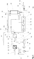
- a method according to the invention is shown schematically.
- a knife rotor which is assigned to a perforated plate 8 is located in a process chamber 10.
- the knife rotor and the perforated plate 8 form a conventional underwater pelletizer.
- the process chamber 10 is successively supplied with hot process fluid 12, usually hot process water.
- a plastic melt 14 is introduced into the process chamber 10 via the perforated plate 8, which, as plastic strands in the Perforated plate 8 emerging and cut into plastic granules 16 by the knife rotor.
- a mixture 18 of plastic granulate 16 and process water 12 is thus formed.
- the plastic melt consists of a plastic, for example thermoplastic polyester or co-polyester, for example polyethylene terephthalate.
- the plastic melt 14 is also pressed as a function of the speed of the knife rotor through the perforated plate 8.
- the cooling areas can be determined by correspondingly coordinating the speeds of the passage of the plastic melt through the perforated plate 8 in relation to the rotational speed of the knife rotor and the temperature of the process water 12. Cooling by convection is preferred, since this results in the best surface quality and thus the quality of the plastic granulate 16.
- the process water 12 has a temperature in the process chamber 10 which is in a range from 120 ° C. to 160 ° C.
- a process pressure in the process chamber and in the sections of the process described below which are greater than the pressure of the vapor pressure curve of the process water 12, but at least 2.0 bar.
- the plastic granulate 16 is fed to a mixing area 24 via a line 20 and a separating device 22, in which the mixture 18 of plastic granulate 16 and process water 12 is separated from one another.
- the area from the process chamber 10 via line 20 and the separating device 22 forms a first cooling section 25.
- the process water 12 separated from the mixture 18 in the separating device 22 is fed to a process water reservoir 26. From there, the process water 12 is fed via a filter 28, a pump 30 to a heat exchanger 32, in which the process water 12 is heated again to the required process temperature required in the process chamber 10. For this purpose, heating medium 34 is supplied to the heat exchanger 32. Filter residues 36 are removed from the filter 28. The process water 12 heated in the heat exchanger 32 is then fed back to the process chamber 10.
- the plastic granulate 16 is mixed with dry air 38 to form a mixture 40.
- the dry air 38 detects the plastic granules 16 in the mixing area 24 after the first separating device 22 with a dew point of -25 ° C to -40 ° C.
- the temperature of the dry air 38 is in a range from 180 ° C to 210 ° C.
- the mixture 40 is fed to a pressure lock 42, for example in the form of an impeller lock, where the pressure level is at ambient pressure is lowered.
- the dryer air 38 also has a predetermined dew point.
- the mixture 40 is fed to a dealdehydization tank 46 via a valve 48a and a crystallization section 44. The speed of the mixture is controlled by the crystallization section 44 via the valve 48a.
- dry air 38 is branched off and fed to the dealdehydization tank 46 in the lower region as purge air 38a.
- the quantity to be branched is regulated / controlled via a valve 48b.
- the mixture 40 of plastic granules 16 and dry air 38 passes through the crystallization section 44.
- the length of time in the crystallization section 44 is determined via the length of the crystallization section 44 but also via the flow rate of the dry air 38.
- the plastic granules 16 have a surface temperature of 165 ° C. to 185 ° C. before entering the dealdehydization container 46.
- the mixture 40 of plastic granules 16 and dry air 38 enters the dealdehydization tank 46. This part of the dry air 38 serves as further purge air 38b.
- the dealdehydization container 46 has an outlet 50 in the upper region, via which the purge air 38a and the further purge air 38b are fed back to a dry air treatment device 52.
- the dry air treatment device 52 has a fresh air supply 54, a fresh air filter 56, a control valve 58 for setting the required amount of fresh air, a pump 60 and a treatment unit 62, which consists of temperature control and dehumidification.
- Acetal aldehyde and excess water are removed by absorption on molecular sieves or similar substances and processes known to the person skilled in the art.
- Acetal aldehyde largely breaks down into water and carbon dioxide.
- the purge air 38c consisting of the purge air 38a and 38b, emerging from the dealdehydization tank 46 via the outlet 50 is fed to the fresh air 54 after the control valve 58.
- the purge air 38 c and the fresh air 54 form the new dry air 38, so that the circuit is closed.
- the plastic granules 16 emerge from the dealdehydization container 46 at a temperature of greater than 200 ° C. via a lock 64.
- the plastic granulate 16 has a granulate weight of 8 to 36 mg, in particular 12 to 24 mg.
- the underwater congratulations in the process chamber 10 are coordinated accordingly.
- the deviation of the weight of the plastic granules 16 is a maximum of 10% from a weight average of the plastic granules.
- the mean value relates to a statistically relevant proportion of plastic granules 16 in a small time window after the dealdehydization tank 46, that is to say the process tract.
- the plastic granulate 16 is fed to a further cooling section 66 with a cooling fluid, in which the plastic granulate 16 is cooled to less than 65 ° C. at a cooling fluid temperature of less than 40 ° C.
- the cooling fluid has a loading density of more than 30% by weight of plastic granules 16 in the further cooling section 66.
- the plastic granulate 16 consists of a partially crystalline thermoplastic polyester or co-polyester, for example polyethylene terephthalate.
- the pressure is not reduced until after the dealdehydization tank 46.
- the purge air 38c is therefore only supplied to the fresh air 54 after the high-pressure fan 60, since the purge air 38c is still under pressure.
- a pressure of more than 2 bar in the dry air 38 is maintained.
- a pressure reduction, in particular to atmospheric pressure, takes place only after the dealdehydization tank 46.
- the pressure in the dealdehydization tank 46 is less than 10 bar.
- the dew point is kept constant at less than 0 ° C. at atmospheric pressure.
- the pressure is reduced by a rotary valve 64a.
- this can also be done via a lock or via an intermediate chamber with a slide at the entrance and a slide at the exit and mutual opening of the slide.
- the quality of the plastic granules is considerably improved by the method according to the invention. A constant high viscosity or a high molecular weight of the plastic is guaranteed. This is therefore much more suitable to produce higher quality products.
Landscapes
- Chemical & Material Sciences (AREA)
- Engineering & Computer Science (AREA)
- Health & Medical Sciences (AREA)
- Mechanical Engineering (AREA)
- Organic Chemistry (AREA)
- Chemical Kinetics & Catalysis (AREA)
- Life Sciences & Earth Sciences (AREA)
- Molecular Biology (AREA)
- General Engineering & Computer Science (AREA)
- Medicinal Chemistry (AREA)
- Polymers & Plastics (AREA)
- Processing And Handling Of Plastics And Other Materials For Molding In General (AREA)
Description
- Die Erfindung betrifft ein Verfahren zur Herstellung eines Kunststoffgranulats gemäß der im Oberbegriff des Patentanspruches 1 angegebenen Art.
-
DE 10 2007 040 135 A1 betrifft ein Verfahren zur kontinuierlichen Herstellung von Polyester-Granulaten aus hochviskosen Polyester-Schmelzen mit einem Polymerisationsgrad von 132 bis 165. Die hochviskose Schmelze (hiV) wird mittels einer Dosierpumpe, die einen Druck von> 80 bar bis 200 bar aufbauen kann, durch eine beheizte Düsenplatte 3 gepresst (Unterwassergranulierung unter mindestens 1 bar Überdruck mit einer Wassereintrittstemperatur von mindestens 70°C, bevorzugt 80-95°C). Ein eng an dieser laufender Schneidmesserkranz schält die Schmelze von jedem Loch der Düsenplatte ab, wodurch sich runde oder ovale Körner (Pellets) ausbilden, die durch eine intensive Wasserumspülung an der Oberfläche amorph erstarren. Die Wasserkammer steht unter leichtem Überdruck und das Flottenverhältnis beträgt zwischen 8 und 12:1. Das Pellet/Wassergemisch gelangt über eine kurze Rohrleitung und einen Agglomeratabscheider in den Vortrockner, der als Rührzentrifuge ausgebildet ist, wobei die Wasserabscheidung im unteren Bereich stattfindet und die Pellets im oberen Bereich austreten. -
EP 2 712 881 A1 offenbart eine Vorrichtung zum kontinuierlichen Pelletisieren und Kristallisieren eines Polymers, die eine Einheit zum Bilden eines Polymerpelletmaterials und eines Kühlpelletmaterials in einem flüssigen Kühlmedium umfasst. Zudem ist eine nachgeschaltete Einheit zum Trocknen von Pelletmaterial und ein Kristallisator zum Kristallisieren von Pelletmaterial vorgesehen. Der Kristallisator kommuniziert direkt über die Verbindungsleitung mit der vorgeschalteten Einheit zum Trennen des flüssigen Kühlmediums vom Pelletmaterial und Trocknen des Pelletmaterials, so dass das zu behandelnde Material ungehindert von der vorgeschalteten Einheit zur nachfolgenden Einheit gelangen kann. Ein Einlass dient zum Importieren von Inertgas. Eine Vorrichtung zum kontinuierlichen Pelletisieren und Kristallisieren eines Polymers umfasst: Eine Einheit zum Bilden eines Polymerpelletmaterials und zum Kühlen des Pelletmaterials in einem flüssigen Kühlmedium; eine nachgeschaltete Einheit zum Trocknen des Pelletmaterials, wobei die nachgeschaltete Einheit eine Austrittsöffnung zum Exportieren von Gas aufweist; und einen Kristallisator zum Kristallisieren des Pelletmaterials. Der Kristallisator kommuniziert direkt über eine Verbindungsleitung mit der vorverbundenen Einheit zum Trennen des flüssigen Kühlmediums vom Pelletmaterial und zum Trocknen des Pelletmaterials, so dass das zu behandelnde Material ungehindert von der vorverbundenen Einheit passieren kann zur nachgeschalteten Einheit; und umfasst einen Einlass zum Einleiten von Inertgas, wobei der Kristallisator über den Einlass mit einem Inertgastank in Verbindung steht, so dass der Druck im Kristallisator relativ zu einem Druck in der Einheit zum Trocknen des Pelletmaterials erhöht werden kann. - Aus der
EP 2 361 174 B1 ist ein Verfahren zur Herstellung von Kunststoffgranulat mit hoher Erweichungstemperatur, nämlich über 120°C, bekannt. Solche Kunststoffgranulate können dabei Polycarbonat, Polycarbonatblend, Polystyrol, Hochtemperatur-Thermoplaste sein. Ein Prozessfluid ist dabei in einer Prozesskammer enthalten. Die Prozesskammer ist von einer Lochplatte zur Erzeugung von Strängen aus flüssigem Kunststoff teilweise begrenzt. In der Prozesskammer wirkt eine Zerteilvorrichtung mit der Lochplatte für die aus der Lochplatte austretenden Kunststoffstränge zusammen. Dabei entsteht ein Gemisch aus Prozessfluid und Granulat. Das Prozessfluid hat dabei eine Temperatur von größer als 120°C. In der Prozesskammer herrscht ein Druck von größer als 2 bar. Das Gemisch aus Prozessfluid und Granulat durchläuft unter Aufrechterhaltung des Drucks eine Kühlstrecke. Das Granulat wird dann unter Druck vom Prozessfluid in einer Trennvorrichtung getrennt und über eine Druckschleuse geleitet. Dieses Verfahren hat sich grundsätzlich bewährt. Jedoch ist die Qualität der Kunststoffgranulate für die weitere Verarbeitung für bestimmte Anwendungen weiter zu gering. - Aus der
DE 10 2006 027 176 B4 ist ein Verfahren zur Herstellung eines Kunststoffgranulats mit geringem Acetaldehydgehalt aus einer hochviskosen Polyesterschmelze mit einer intrinsischen Viskosität zwischen 0,6 und 1,0 dl/g bekannt. Hierbei wird der Polyesterschmelzstrang unter Wasser bei einer Temperatur von mindestens 90°C zerteilt. Das begleitende Wasser wird anschließend unter möglichst geringer Abkühlung des Kunststoffgranulats vom Kunststoffgranulat getrennt, sodass das Kunststoffgranulat nach Abtrennung des Wassers eine Temperatur von mindestens 130°C aufweist. Das so erhaltene wasserarme Kunststoffgranulat nach der Wasserabtrennung wird in einen Dealdehydisierungsbehälter gegeben und dort mittels eines Spülluftstroms mit einer Eintrittstemperatur zwischen 180°C und 200°C behandelt. Dabei wird das Kunststoffgranulat entweder direkt in den Dealdehydisierungsbehälter gegeben oder mittels einer Dosiereinrichtung. Hierdurch soll das Verfahren apparativ vereinfacht und mit geringeren Betriebskosten betrieben werden. Zudem sollen die besonders hohen Qualitätsansprüche an den Polyester für Verpackungen bezüglich Viskosität, Farbe, Acetaldehydgehalt, Acetaldehydreformation sowie auf Schmelzverhalten beibehalten bzw. verbessert werden. Nachteilig an diesem Verfahren ist auch hier, dass die Qualität des Kunststoffgranulats für bestimmte Anwendungen nicht zufriedenstellend ist. - Aufgabe der Erfindung ist es daher, ein Verfahren zur Herstellung eines Kunststoffgranulats anzugeben, das Kunststoffgranulat mit einer höheren Qualität im Hinblick auf Viskosität, Farbe, Acetaldehydgehalt, Aufschmelzverhalten und Ähnliches erzeugt. Insbesondere soll dabei der apparative Aufwand möglichst gering gehalten und das Verfahren mit möglichst geringen Betriebskosten betrieben werden.
- Diese Aufgabe wird durch die kennzeichnenden Merkmale des Patentanspruches 1 gelöst.
- Die Unteransprüche bilden vorteilhafte Ausführungsformen des erfindungsgemäßen Verfahrens.
- Der Erfindung liegt die Erkenntnis zugrunde, dass sowohl die Prozessparameter bei der Kunststoffgranulierung, welche für die Nukleierung zur Beeinflussung der Kristallisation, als auch für die Kristallisation als solche verantwortlich sind, aber auch eine Dealdehydisierung der Kunststoffgranulate die Qualität der Kunststoffgranulate erheblich beeinflussen und daher beide Maßnahmen kombiniert mit angepassten und aufeinander abgestimmten Parametern zu einer besseren Qualität der Kunststoffgranulate insgesamt führen. Zudem ergeben sich dadurch weitere Möglichkeiten das Verfahren im Hinblick auf die Betriebskosten zu optimieren und die Qualität der Kunststoffgranulate zu verbessern.
- Nach der Erfindung ist daher ein Verfahren zur Herstellung eines Kunststoffgranulats angegeben, bei dem ein Prozessfluid in einer Prozesskammer enthalten ist. In der Prozesskammer findet eine Unterwassergranulierung statt. Das Prozessfluid weist dabei in der Prozesskammer eine Temperatur auf, die in einem Temperaturbereich von größer oder gleich 120°C bis maximal 160°C liegt. Zudem herrscht in der Prozesskammer ein Prozessdruck von größer als der Druck der Dampfdruckkurve des Prozessfluids (12), jedoch mindestens 2,0 bar. Unter diesem Prozessdruck erfolgt ein Granulieren der Kunststoffstränge zu Kunststoffgranulat. Aus der Prozesskammer wird dann ein Gemisch von Prozessfluid und Kunststoffgranulat unter Abkühlung des Kunststoffgranulats in eine erste Kühlstrecke abgeleitet, wobei i in einer ersten Trennvorrichtung das Kunststoffgranulat unter Prozessdruck vom Prozessfluid getrennt wird. Anschließend wird das Kunststoffgranulat dann in Linie kontinuierlich einem Dealdehydisierungsbehälter zugeführt. In der ersten Kühlstrecke wird der Prozessdruck aufrechterhalten und ein gezieltes Nukleieren, also die Generierung von Kristallisationskeimen, an der Oberfläche des Kunststoffgranulats durch eine optimierte Kühltemperatur ermöglicht, sodass das Kunststoffgranulat optimierte Voraussetzungen für die Kristallisation hat und dem Dealdehydisierungsbehälter zugeführt werden kann. Im Dealdehydisierungsbehälter wird das Kunststoffgranulat mit einem Spülgas, insbesondere Spülluft, behandelt, um den Acetaldehydgehalt des Kunststoffgranulats zu verringern. Der Einsatz von Spülgas ist besonders einfach und spart, insbesondere bei Verwendung von Spülluft, erheblich Betriebskosten.
- Vorzugsweise ist die Prozesskammer von einer Lochplatte zur Erzeugung von Strängen aus flüssigem Kunststoff teilweise begrenzt. In der Prozesskammer wirkt eine Zerteilvorrichtung mit der Lochplatte für die aus der Lochplatte austretenden Kunststoffstränge zusammen, und es erfolgt die Unterwassergranulierung durch die Zerteilvorrichtung in dem Prozessfluid an der Lochplatte in der Prozesskammer. Es hat sich gezeigt, dass unter diesen Bedingungen für die Weiterverarbeitung des Kunststoffgranulats günstige Oberflächenformen entstehen. Hierdurch wird zudem auch der Grad an Vakuolenfreiheit im mit diesem Verfahren hergestellten Kunststoffgranulat weiterhin erhöht.
- Gemäß einer Ausführungsform wird nach der ersten Trennvorrichtung das Kunststoffgranulat unmittelbar durch Trockengas, insbesondere Trockenluft, über eine Kristallisationsstrecke zu einem Dealdehydisierungsbehälter gefördert. Durch dieses zweistufige Abkühlen des Kunststoffgranulats wird zum einen erreicht, dass die Oberflächengüte des Kunststoffgranulats verbessert wird, und zum anderen, dass die Kristallisation des Kunststoffgranulats zielgerichtet über die Trockenluftparameter beeinflusst und somit optimiert werden kann. Zudem wird ein Verkleben der Kunststoffgranulate verhindert.
- Vorzugsweise wird das Trockengas mit den Kunststoffgranulaten zusammen in den Dealdehydisierungsbehälter hineingeführt und dient als weiteres Spülgas. Hierbei ist das Trockengas sowohl Transportmedium für das Kunststoffgranulat zum Dealdehydisierungsbehälter als auch Behandlungsmedium in dem Dealdehydisierungsbehälter für das dort eingebrachte Kunststoffgranulat, wodurch sich ebenfalls der apparative und energetische Aufwand verringern lässt.
- Gemäß einer Ausführungsform der Erfindung wird das Kunststoffgranulat in den Dealdehydisierungsbehälter mit einer Oberflächentemperatur in Höhe von 165°C bis 185°C eingebracht. Das Kunststoffgranulat weist dadurch von Anfang an eine Temperatur auf, welche den Dealdehydisierungsprozess im Dealdehydisierungsbehälter begünstigt.
- Vorzugsweise erfasst das Trockengas die Kunststoffgranulate nach der ersten Trennvorrichtung mit einem Taupunkt von -25°C bis -40°C. Hierdurch wird vermieden, dass während des Transports des Kunststoffgranulat Wasser an dem Kunststoffgranulat kondensiert und die Kristallisation ungewollt negativ beeinflusst.
- Insbesondere erfasst dabei das Trockengas die Kunststoffgranulate nach der ersten Trennvorrichtung mit einer Temperatur von 180°C bis 210°C, welche während des Transports den Kristallisationsprozess begünstigt. Über die entsprechende Transportgeschwindigkeit und/oder die Länge der Kristallisationsstrecke kann der Kristallisationsgrad der Kunststoffgranulate festgelegt werden, mit dem die Kunststoffgranulate in den Dealdehydisierungsbehälter eintreten.
- Durch die Unterwassergranulierung werden bevorzugt Kunststoffgranulate erzeugt, die nach dem Dealdehydisierungsbehälter ein mittleres Gewicht eines Kunststoffgranulats in einem Bereich von 8 bis 36 mg, insbesondere 12 bis 24 mg, aufweisen. Je kleiner das Kunststoffgranulat ist, umso besser ist dies für die Diffusionsvorgänge. Insbesondere kann dann das Aldehyd leichter dem Kunststoffgranulat entzogen werden. Ein kleineres Kunststoffgranulat kühlt aber schneller ab, was die Kristallisation wieder negativ beeinflusst. Insofern ist der angegebene Wert ein Kompromiss zwischen den gegenteiligen Anforderungen während des Prozesses an das Kunststoffgranulat. Die Gewichtsangaben beziehen sich auf das mittlere Gewicht der Kunststoffgranulate, mit einer Toleranz des Gewichts der Kunststoffgranulate von maximal 10%. Dies hat den Vorteil, dass das Kunststoffgranulat homogen kristallisiert und einfacher weiter zu verarbeiten ist.
- Um den apparativen Aufwand weiter zu optimieren, bildet ein Teil des Trockengases auch das Spülgas für den Dealdehydisierungsbehälter, in dem ein Teil des Trockengases, insbesondere vor der Kristallisationstrecke, abgezweigt und als Spülgas dem Dealdehydisierungsbehälter zugeführt wird. Dadurch bedarf es nur einer Gasaufbereitungseinheit, nämlich eine Gasaufbereitung für das Trockengas. Hierdurch wird der apparative und energetische Aufwand des Verfahrens weiter optimiert.
- Auf einfache Weise wird ein geschlossener Kreislauf dadurch erzeugt und kann Energie aus dem Spülgas dem weiteren Verfahren wieder zur Verfügung gestellt werden, in dem über einen Ausgang an dem Dealdehydisierungsbehälter ein aus dem mit den Kunststoffgranulaten in den Dealdehydisierungsbehälter eingebrachten Trockengas - weiteres Spülgas - und aus dem in den Dealdehydisierungsbehälter eingebrachten Spülgas bestehendes Prozessgas, insbesondere zusammen mit einem die benötigte Menge Trockengas ergänzenden Frischgas, einer Gasaufbereitung zugeführt wird, welche dieses Gas als Trockengas aufbereitet und dem Kunststoffgranulat nach der ersten Trennvorrichtung wieder zuführt.
- Nach der ersten Trennvorrichtung kann das Verfahren beispielsweise in zwei verschiedenen Alternativen weiterbetrieben werden:
- Zum einen ist es möglich, dass nach der ersten Trennvorrichtung und vor der Kristallisationsstrecke eine solche Druckreduktion erfolgt, dass ein vorgegebener Taupunkt des Trockengases gewährleistet ist. Dies hat den Vorteil, dass insbesondere die Kristallisationsstrecke und der Dealdehydisierungsbehälter einfacher aufgebaut sein können, da kein Prozessdruck mehr herrscht.
- Zum anderen ist es jedoch auch möglich, dass ausgehend von der ersten Trennvorrichtung bis zum Dealdehydisierungsbehälter und im Dealdehydisierungsbehälter ein Druck von mehr als 2 bar im Trockengas bzw. Spülgas aufrechterhalten wird und nach dem Dealdehydisierungsbehälter eine Druckreduktion erfolgt, insbesondere auf Atmosphärendruck. Nachdem das Kristallisieren und das Dealdehydisieren unter Druck stattfinden, ist der Parameterbereich, der durch physikalische Grenzen gesetzt ist, erweitert. Vorzugsweise beträgt dabei der Druck im Dealdehydisierungsbehälter kleiner als 10 bar.
- Die Druckreduktion nach dem Dealdehydisierungsbehälter kann über eine Zellradschleuse oder eine Schleuse oder über eine Zwischenkammer mit einem Schieber am Eingang und einem Schieber am Ausgang und wechselseitigem Öffnen der Schieber erfolgen.
- Gemäß einer vorteilhaften Weiterbildung der Erfindung wird während der Dealdehydisierung der Druck im Dealdehydisierungsbehälter im Bereich des Taupunkts bei Atmosphärendruck von kleiner 0°C konstant gehalten.
- Nach der Dealdehydisierung kann das Kunststoffgranulat einer weiteren Kühlstrecke mit einem Kühlfluid zugeführt werden, in der das Kunststoffgranulat bei einer Kühlfluidtemperatur von kleiner als 40°C auf kleiner 65°C gekühlt wird.
- Vorzugsweise weist dabei das Kühlfluid eine Beladungsdichte von mehr als 30 Gew.-% Kunststoffgranulate in der weiteren Kühlstrecke auf.
- Das Kunststoffgranulat besteht insbesondere aus einem teilkristallinen thermoplastischen Polyester oder Co-Polyester, beispielsweise Polyethylenterephthalat, da hier die oben genannten Vorteile besonders zum Tragen kommen.
- Weitere Vorteile, Merkmale und Anwendungsmöglichkeiten der vorliegenden Erfindung ergeben sich aus der nachfolgenden Beschreibung in Verbindung mit den in den Zeichnungen dargestellten Ausführungsbeispielen.
- In der Beschreibung, in den Ansprüchen und in der Zeichnung werden die in der unten aufgeführten Liste der Bezugszeichen verwendeten Begriffe und zugeordneten Bezugszeichen verwendet. In der Zeichnung bedeutet:
- Fig. 1
- eine schematische Ansicht eines Herstellungsprozesses von Kunststoffgranulat gemäß einer ersten Ausführungsform;
- Fig. 2
- eine schematische Ansicht eines Herstellungsprozesses von Kunststoffgranulat gemäß einer zweiten Ausführungsform, und
- Fig. 3
- eine schematische Ansicht eines Herstellungsprozesses von Kunststoffgranulat gemäß einer dritten Ausführungsform.
- In
Fig. 1 ist ein Verfahren nach der Erfindung schematisch dargestellt. In einer Prozesskammer 10 befindet sich ein Messerrotor, der einer Lochplatte 8 zugeordnet ist. Der Messerrotor und die Lochplatte 8 bilden einen üblichen Unterwassergranulator. Der Prozesskammer 10 wird sukzessive heißes Prozessfluid 12, in der Regel heißes Prozesswasser, zugeführt. Zudem wird eine Kunststoffschmelze 14 über die Lochplatte 8 in die Prozesskammer 10 eingebracht, welche als Kunststoffstränge bei der Lochplatte 8 austretenden und durch den Messerrotor in Kunststoffgranulate 16 geschnitten werden. Es entsteht somit ein Gemisch 18 aus Kunststoffgranulat 16 und Prozesswasser 12. - Die Kunststoffschmelze besteht dabei aus einem Kunststoff, zum Beispiel thermoplastischer Polyester oder Co-Polyester, beispielsweise Polyethylenterephthalat. Die Kunststoffschmelze 14 wird zudem in Abhängigkeit von der Geschwindigkeit des Messerrotors durch die Lochplatte 8 gepresst. Durch entsprechende Abstimmung der Geschwindigkeiten des Durchtritts der Kunststoffschmelze durch die Lochplatte 8 im Verhältnis zur Drehgeschwindigkeit des Messerrotors sowie der Temperatur des Prozesswassers 12 lassen sich die Abkühlbereiche festlegen. Bevorzugt ist die Abkühlung nur durch Konvektion, da hierdurch die Oberflächengüte und somit die Qualität des Kunststoffgranulats 16 am besten ist.
- Das Prozesswasser 12 weist in der Prozesskammer 10 eine Temperatur auf, die in einem Bereich von 120°C bis 160°C liegt. Zudem herrscht in der Prozesskammer sowie in den im Folgenden noch beschriebenen Abschnitten des Prozesses ein Prozessdruck von größer als dem Druck der Dampfdruckkurve des Prozesswassers 12, jedoch mindestens 2,0 bar.
- Über eine Leitung 20 und eine Trennvorrichtung 22, in der das Gemisch 18 aus Kunststoffgranulat 16 und Prozesswasser 12 voneinander getrennt wird, wird das Kunststoffgranulat 16 einem Mischbereich 24 zugeführt. Der Bereich von der Prozesskammer 10 über Leitung 20 und der Trennvorrichtung 22 bildet eine erste Kühlstrecke 25.
- Das in der Trennvorrichtung 22 von dem Gemisch 18 abgetrennte Prozesswasser 12 wird einem Prozesswasserspeicher 26 zugeführt. Von dort aus wird das Prozesswasser 12 über einen Filter 28, eine Pumpe 30 einem Wärmetauscher 32 zugeführt, in dem das Prozesswasser 12 wieder auf die erforderliche, in der Prozesskammer 10 benötigte Prozesstemperatur erhitzt wird. Hierfür wird dem Wärmetauscher 32 Heizmedium 34 zugeführt. Vom Filter 28 werden Filterrückstände 36 abgeführt. Das im Wärmetauscher 32 erhitzte Prozesswasser 12 wird dann wieder der Prozesskammer 10 zugeführt.
- In dem Mischbereich 24 wird das Kunststoffgranulat 16 mit Trockenluft 38 zu einem Gemisch 40 vermischt. Die Trockenluft 38 erfasst die Kunststoffgranulate 16 im Mischbereich 24 nach der ersten Trennvorrichtung 22 mit einem Taupunkt von -25°C bis -40°C. Dabei liegt die Temperatur der Trockenluft 38 in einem Bereich von 180°C bis 210°C. Das Gemisch 40 wird einer Druckschleuse 42, beispielsweise in Form einer Impellerschleuse, zugeführt, wo das Druckniveau auf Umgebungsdruck abgesenkt wird. Die Trocknerluft 38 weist dabei weiter einen vorgegebenen Taupunkt auf. Das Gemisch 40 wird über ein Ventil 48a und einer Kristallisationsstrecke 44 einem Dealdehydisierungsbehälter 46 zugeführt. Über das Ventil 48a wird die Geschwindigkeit des Gemisches durch die Kristallisationsstrecke 44 gesteuert.
- Nach der Druckschleuse 42 wird Trockenluft 38 abgezweigt und als Spülluft 38a dem Dealdehydisierungsbehälter 46 im unteren Bereich zugeführt. Über ein Ventil 48b wird die abzuzweigende Menge geregelt/gesteuert.
- Das Gemisch 40 aus Kunststoffgranulat 16 und Trockenluft 38 durchläuft die Kristallisationsstrecke 44. Über die Länge der Kristallisationsstrecke 44 aber auch über die Strömungsgeschwindigkeit der Trockenluft 38 wird die Verweildauer in der Kristallisationsstrecke 44 bestimmt. Die Kunststoffgranulate 16 haben vor Eintritt in den Dealdehydisierungsbehälter 46 eine Oberflächentemperatur von 165°C bis 185°C. Das Gemisch 40 aus Kunststoffgranulaten 16 und Trockenluft 38 tritt in den Dealdehydisierungsbehälter 46 ein. Dieser Teil der Trockenluft 38 dient dabei als weitere Spülluft 38b.
- Der Dealdehydisierungsbehälter 46 weist im oberen Bereich einen Ausgang 50 auf, über den die Spülluft 38a und die weitere Spülluft 38b einer Trockenluftaufbereitungsvorrichtung 52 wieder zugeführt wird. Die Trockenluftaufbereitungsvorrichtung 52 weist eine Frischluftzufuhr 54, einen Frischluftfilter 56, eine Steuer/Regelventil 58 zur Einstellung der benötigten Frischluftmenge, eine Pumpe 60 sowie eine Aufbereitungseinheit 62 auf, die aus Temperierung und Entfeuchtung besteht. Dabei werden Acetalaldehyd und überschüssiges Wasser mittels Absorption an Molekularsieb oder ähnlichen, dem Fachmann bekannten Substanzen und Verfahren entfernt. Acetalaldehyd zerfällt dabei weitgehend in Wasser und Kohlendioxid. Die aus dem Dealdehydisierungsbehälter 46 über den Ausgang 50 austretende Spülluft 38c, bestehend aus der Spülluft 38 a und 38 b, wird der Frischluft 54 nach dem Steuer-/Regelventil 58 zugeführt. Die Spülluft 38 c und die Frischluft 54 bilden die neue Trockenluft 38, so dass der Kreislauf geschlossen ist.
- Aus dem Dealdehydisierungsbehälter 46 treten die Kunststoffgranulate 16 mit einer Temperatur von größer als 200°C über eine Schleuse 64 aus. Dabei weist das Kunststoffgranulat 16 ein Granulatgewicht von 8 bis 36 mg, insbesondere 12 bis 24 mg auf. Entsprechend ist die Unterwassergratulation in der Prozesskammer 10 abgestimmt. Die Abweichung des Gewichts der Kunststoffgranulate 16 beträgt maximal 10 % von einem Gewichtsmittelwert der Kunststoffgranulate. Der Mittelwert bezieht sich dabei auf einen statistisch relevanten Anteil von Kunststoffgranulaten 16 in einem kleinen Zeitfenster nach dem Dealdehydisierungsbehälter 46, also dem Prozesstrakt.
- Nach dem Dealdehydisierungsbehälter 46 wird das Kunststoffgranulat 16 einer weiteren Kühlstrecke 66 mit einem Kühlfluid zugeführt, in dem das Kunststoffgranulat 16 bei einer Kühlfluidtemperatur von kleiner als 40°C auf kleiner 65°C gekühlt wird. Dabei weist das Kühlfluid eine Beladungsdichte von mehr als 30 Gew.-% Kunststoffgranulate 16 in der weiteren Kühlstrecke 66 auf.
- Das Kunststoffgranulat 16 besteht aus einem teilkristallinen thermoplastischen Polyester oder Co-Polyester, beispielsweise Polyethylenterephthalat.
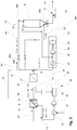
- In den
Figuren 2 und3 ist eine weitere Ausführungsform dargestellt. Hierbei wird der Prozessdruck so lange aufrechterhalten, bis die Kunststoffgranulate 16 den Dealdehydisierungsbehälter 46 verlassen. - Aus diesem Grund erfolgt eine Druckreduktion erst nach dem Dealdehydisierungsbehälter 46. Die Spülluft 38c wird daher erst nach dem Hochdruckgebläse 60 der Frischluft 54 zugeführt, da die Spülluft 38c noch unter Druck steht. Ausgehend von der ersten Trennvorrichtung 22 bis zum Dealdehydisierungsbehälter 46 wird ein Druck von mehr als 2 bar in der Trockenluft 38 aufrechterhalten. Erst nach dem Dealdehydisierungsbehälter 46 erfolgt eine Druckreduktion, insbesondere auf Atmosphärendruck. Der Druck im Dealdehydisierungsbehälter 46 ist dabei kleiner als 10 bar. Während der Dealdehydisierung im Dealdehydisierungsbehälter 46 unter Druck wird der Taupunkt bei Atmosphärendruck von kleiner 0°C konstant gehalten.
- Gemäß
Figur 2 erfolgt die Druckreduktion durch eine Zellenradschleuse 64a. Alternativ kann dies auch über eine Schleuse, oder über eine Zwischenkammer mit einem Schieber am Eingang und einem Schieber am Ausgang und wechselseitigem Öffnen der Schieber erfolgen. - Gemäß
Figur 3 ist der Schleuse 64 eine Druckschleuse 70 nachgeschaltet. Ansonsten laufen die Verfahren entsprechend ab und die entsprechenden Vorrichtungen in der anhand vonFigur 1 beschriebenen Weise in Linie vorgesehen. Ein Vorteil des Verfahrens ist auch die Fertigung der Kunststoffgranulate in Linie, d.h. kontinuierlich und nicht sequenziell. - Zudem wird durch die in dem Verfahren beschriebene Direktkristallisation Energie eingespart, da zum einen in der Kunststoffschmelze enthaltene Energie für die Kristallisation genutzt wird und zum anderen eine Zwischenlagerung entfällt.
- Ferner wird auf Grund des gesenkten Aldehydgehalts eine bessere Verträglichkeit des Kunststoffgranulats mit Produkten, mit denen es in Kontakt kommt, erreicht.
- Durch das erfindungsgemäße Verfahren wird die Qualität der Kunststoffgranulate erheblich verbessert. Eine konstant hohe Viskosität bzw. ein hohes Molekulargewicht des Kunststoffs wird gewährleistet. Dieses ist daher weitaus besser geeignet um hochwertigere Produkte herzustellen.
-
- 8
- Lochplatte
- 10
- Prozesskammer
- 12
- Prozessfluid, Prozesswasser
- 14
- Kunststoffschmelze
- 16
- Kunststoffgranulat
- 18
- Gemisch aus Prozessfluid 12 und Kunststoffgranulat 16
- 20
- Leitung
- 22
- Trennvorrichtung
- 24
- Mischkammer
- 25
- erste Kühlstrecke
- 26
- Prozesswasserspeicher
- 28
- erster Filter
- 30
- erste Pumpe
- 32
- erster Wärmetauscher
- 34
- Heizmedium
- 36
- Filterrückstände
- 38
- Trockenluft
- 38a
- Spülluft
- 38b
- Spülluft
- 38c
- Spülluft
- 40
- Gemisch aus Kunststoffgranulat 16 und Trockenluft 38
- 42
- Druckschleuse
- 44
- Kristallisationsstrecke
- 46
- Dealdehydisierungsbehälter
- 48a
- Steuer-/Regelventil
- 48b
- Steuer-/Regelventil
- 50
- Ausgang aus dem Dealdehydisierungsbehälter 46
- 52
- Trockenluftaufbereitungsvorrichtung
- 56
- Frischluftfilter
- 58
- Steuer-/Regelventil für die Frischluft
- 60
- Hochdruckgebläse
- 62
- Aufbereitungseinheit aus Entfeuchtung und Temperierung
- 64
- Schleuse des Dealdehydisierungsbehälter 46
- 64a
- Zellenradschleuse
- 66
- weitere Kühlstrecke
- 68
- weiteres Kühlfluid
- 70
- Druckschleuse
Claims (18)
- Verfahren zur Herstellung eines Kunststoffgranulats (16), bei dem ein Prozessfluid (12) in einer Prozesskammer (10) enthalten ist, in der Prozesskammer (10) eine Unterwassergranulierung stattfindet, das Prozessfluid (12) in der Prozesskammer (10) eine Temperatur aufweist, die in einem Temperaturbereich von 120°C bis 160°C liegt, in der Prozesskammer (10) ein Prozessdruck von mindestens 2,0 bar herrscht und ein Granulieren der Kunststoffstränge (14) zu Kunststoffgranulat (16) unter diesem Prozessdruck erfolgt, aus der Prozesskammer (10) ein Gemisch (18) von Prozessfluid (12) und Kunststoffgranulat (16) unter Abkühlung des Kunststoffgranulats (16) in eine erste Kühlstrecke (25) abgeleitet wird, in einer ersten Trennvorrichtung (22) das Kunststoffgranulat (16) unter Prozessdruck vom Prozessfluid (12) getrennt wird, dadurch gekennzeichnet, dass in der ersten Kühlstrecke (25) der Prozessdruck aufrechterhalten wird, in der Prozesskammer (10) ein Prozessdruck von größer als der Druck der Dampfdruckkurve des Prozessfluids (12) herrscht, und das Kunststoffgranulat (16) nach der Trennung vom Prozessfluid (12) in der ersten Trennvorrichtung (22) in Linie kontinuierlich einem Dealdehydisierungsbehälter (46) zugeführt wird, in dem das Kunststoffgranulat (16) mit einem Spülgas (38a, 38b), insbesondere Spülluft, behandelt wird, um den Acetaldehydgehalt des Kunststoffgranulats (16) zu verringern.
- Verfahren nach Anspruch 1, dadurch gekennzeichnet, dass die Prozesskammer (10) von einer Lochplatte (8) zur Erzeugung von Strängen aus flüssigem Kunststoff (14) teilweise begrenzt ist, in der Prozesskammer (10) eine Zerteilvorrichtung mit der Lochplatte (8) für die aus der Lochplatte (8) austretenden Kunststoffstränge zusammenwirkt, und die Unterwassergranulierung durch die Zerteilvorrichtung in dem Prozessfluid (12) an der Lochplatte (8) in der Prozesskammer (10) erfolgt.
- Verfahren nach Anspruch 1 oder 2, dadurch gekennzeichnet, dass nach der ersten Trennvorrichtung (22) das Kunststoffgranulat (16), insbesondere unmittelbar, durch Trockengas (38), vorzugsweise Trockenluft, über eine Kristallisationsstrecke (44) zu einem Dealdehydisierungsbehälter (46) gefördert wird.
- Verfahren nach Anspruch 3, dadurch gekennzeichnet, dass das Trockengas (38) mit den Kunststoffgranulaten (16) zusammen in den Dealdehydisierungsbehälter (46) hineingeführt wird und als weiteres Spülgas (40) dient.
- Verfahren nach einem der vorangehenden Ansprüche, dadurch gekennzeichnet, dass das Kunststoffgranulat (16) in den Dealdehydisierungsbehälter (46) mit einer Oberflächentemperatur in Höhe von 165° bis 185°C eingebracht wird.
- Verfahren nach einem der Ansprüche 3 bis 5, dadurch gekennzeichnet, dass das Trockengas (38) die Kunststoffgranulate (16) nach der ersten Trennvorrichtung (22) mit einem Taupunkt von -25°C bis -40°C erfasst.
- Verfahren nach einem der Ansprüche 3 bis 5, dadurch gekennzeichnet, dass das Trockengas (38) die Kunststoffgranulate (16) nach der ersten Trennvorrichtung (22) mit einer Temperatur von 180°C bis 210°C erfasst.
- Verfahren nach einem der vorangehenden Ansprüche, dadurch gekennzeichnet, dass durch die Unterwassergranulierung Kunststoffgranulate (16) erzeugt werden, die nach dem Dealdehydisierungsbehälter (46) ein mittleres Gewicht eines Kunststoffgranulats in einem Bereich von 8 bis 36 mg, insbesondere 12 bis 24 mg, aufweisen.
- Verfahren nach einem der Ansprüche 3 bis 8, dadurch gekennzeichnet, dass ein Teil des Trockengases (38) auch das Spülgas (38a) für den Dealdehydisierungsbehälter (46) bildet, in dem ein Teil des Trockengases (38), insbesondere vor der Kristallisationsstrecke (44), abgezweigt und als Spülgas (38a, 38b, 38c) dem Dealdehydisierungsbehälter (46) zugeführt wird.
- Verfahren nach einem der Ansprüche 3 bis 9, dadurch gekennzeichnet, dass über einen Ausgang (50) an dem Dealdehydisierungsbehälter (46) ein aus dem mit den Kunststoffgranulaten (16) in den Dealdehydisierungsbehälter (46) eingebrachten Trockengas (38b) und dem in den Dealdehydisierungsbehälter (46) eingebrachten Spülgas (38a) bestehendes Prozessgas, insbesondere zusammen mit einem die benötigte Menge Trockengas (38) ergänzenden Frischgas, einer Gasaufbereitung zugeführt wird, welche dieses Gas als Trockengas (38) aufbereitet und dem Kunststoffgranulat (16) nach der ersten Trennvorrichtung (22) wieder zuführt.
- Verfahren nach einem der Ansprüche 3 bis 10, dadurch gekennzeichnet, dass nach der ersten Trennvorrichtung (22) und vor der Kristallisationsstrecke (44) eine solche Druckreduktion erfolgt, dass ein vorgegebener Taupunkt des Trockengases (38) gewährleistet ist.
- Verfahren nach einem der Ansprüche 3 bis 10, dadurch gekennzeichnet, dass ausgehend von der ersten Trennvorrichtung (22) bis zum Dealdehydisierungsbehälter (46) ein Druck von mehr als 2 bar im Trockengas (38) aufrechterhalten wird und nach dem Dealdehydisierungsbehälter (46) eine Druckreduktion erfolgt, insbesondere auf Atmosphärendruck.
- Verfahren nach Anspruch 12, dadurch gekennzeichnet, dass der Druck im Dealdehydisierungsbehälter (46) kleiner als 10 bar beträgt.
- Verfahren nach einem der Ansprüche 3 bis 10 oder 11 bis 13, dadurch gekennzeichnet, dass die Druckreduktion nach dem Dealdehydisierungsbehälter (46) über eine Zellradschleuse (64a) oder eine Schleuse (64) oder über eine Zwischenkammer mit einem Schieber am Eingang und einem Schieber am Ausgang und wechselseitigem Öffnen der Schieber erfolgt.
- Verfahren nach Anspruch 14, dadurch gekennzeichnet, dass während der Dealdyhydisierung unter Druck der Druck im Dealdehydisierungsbehälter (46) im Bereich des Taupunkts bei Atmosphärendruck von kleiner 0°C konstant gehalten wird.
- Verfahren nach einem der vorangehenden Ansprüche, dadurch gekennzeichnet, dass nach der Dealdehydisierung das Kunststoffgranulat (16) einer weiteren Kühlstrecke (66) mit einem Kühlfluid (68) zugeführt wird, in dem das Kunststoffgranulat (16) bei einer Kühlfluidtemperatur von kleiner als 40°C auf kleiner 65°C gekühlt wird.
- Verfahren nach Anspruch 16, dadurch gekennzeichnet, dass das Kühlfluid (68) eine Beladungsdichte von mehr als 30 Gew.-% Kunststoffgranulate (16) in der weiteren Kühlstrecke (66) aufweist.
- Verfahren nach einem der vorangehenden Ansprüche, dadurch gekennzeichnet, dass das Kunststoffgranulat (16) aus einem teilkristallinen thermoplastischen Polyester oder Co-Polyester, beispielsweise Polyethylenterephthalat, besteht.
Applications Claiming Priority (2)
| Application Number | Priority Date | Filing Date | Title |
|---|---|---|---|
| DE102015119787.1A DE102015119787A1 (de) | 2015-11-16 | 2015-11-16 | Verfahren zur Herstellung eines Kunststoffgranulats |
| PCT/EP2016/074886 WO2017084821A1 (de) | 2015-11-16 | 2016-10-17 | Verfahren zur herstellung eines kunststoffgranulats |
Publications (2)
| Publication Number | Publication Date |
|---|---|
| EP3377288A1 EP3377288A1 (de) | 2018-09-26 |
| EP3377288B1 true EP3377288B1 (de) | 2020-04-01 |
Family
ID=57223653
Family Applications (1)
| Application Number | Title | Priority Date | Filing Date |
|---|---|---|---|
| EP16790290.7A Active EP3377288B1 (de) | 2015-11-16 | 2016-10-17 | Verfahren zur herstellung eines kunststoffgranulats |
Country Status (6)
| Country | Link |
|---|---|
| US (1) | US11241665B2 (de) |
| EP (1) | EP3377288B1 (de) |
| CN (1) | CN108463320B (de) |
| DE (1) | DE102015119787A1 (de) |
| TW (1) | TWI607846B (de) |
| WO (1) | WO2017084821A1 (de) |
Cited By (1)
| Publication number | Priority date | Publication date | Assignee | Title |
|---|---|---|---|---|
| US12496753B2 (en) | 2020-08-18 | 2025-12-16 | Evonik Operations Gmbh | Production of high temperature polymer based pellets by underwater pelletization at elevated water temperature to produce (rigid) bead foams |
Families Citing this family (3)
| Publication number | Priority date | Publication date | Assignee | Title |
|---|---|---|---|---|
| DE102015119787A1 (de) | 2015-11-16 | 2017-05-18 | Maag Automatik Gmbh | Verfahren zur Herstellung eines Kunststoffgranulats |
| EP3536470A1 (de) * | 2018-03-06 | 2019-09-11 | Nordson Corporation | Verfahren und vorrichtung zum thermischen behandeln von kunststoffgranulat |
| CN113561358B (zh) * | 2021-08-24 | 2023-05-30 | 揭阳市忠创塑料制品有限公司 | 一种再生塑料颗粒加工冷却设备 |
Family Cites Families (22)
| Publication number | Priority date | Publication date | Assignee | Title |
|---|---|---|---|---|
| JPS6431605A (en) * | 1987-07-28 | 1989-02-01 | Kanegafuchi Chemical Ind | Drying and granulating method of vinyl chloride resin for processing of paste |
| EP1547744B1 (de) * | 2002-07-18 | 2011-09-21 | Kuraray Co., Ltd. | Verfahren zur herstellung von ethylen-vinylalkoholcopolymerpellets |
| ITTO20020714A1 (it) * | 2002-08-09 | 2004-02-10 | Giuliano Cavaglia | Procedimento per la polimerizzazione continua di |
| ITTO20021124A1 (it) * | 2002-12-24 | 2004-06-25 | Giuliano Cavaglia | Reattore e metodo per polimerizzare in continuo in fase solida il polietilentereftalato (pet). |
| DE10310829A1 (de) * | 2003-03-13 | 2004-09-23 | Basf Ag | Thermoplastgranulate |
| US7204945B2 (en) * | 2003-09-16 | 2007-04-17 | Eastman Chemical Company | Direct coupling of melt polymerization and solid state processing for PET |
| US8079158B2 (en) * | 2004-09-02 | 2011-12-20 | Grupo Petrotemex, S.A. De C.V. | Process for separating and drying thermoplastic particles under high pressure |
| CN101438116A (zh) | 2004-09-02 | 2009-05-20 | 伊士曼化工公司 | 高压下分离和干燥热塑性颗粒的方法 |
| AT505475B1 (de) * | 2005-06-14 | 2011-11-15 | Fellinger Markus | Verfahren und anlage zur erhöhung der grenzviskosität von polyestermaterial mittels festphasenpolykondensation |
| DE102006027176B4 (de) * | 2005-08-26 | 2015-08-06 | Lurgi Zimmer Gmbh | Verfahren und Vorrichtung zur Verringerung des Acetaldehydgehaltes von Polyestergranulat sowie Polyestergranulat |
| DE102006012587B4 (de) * | 2006-03-16 | 2015-10-29 | Lurgi Zimmer Gmbh | Verfahren und Vorrichtung zur Kristallisation von Polyestermaterial |
| TW200740586A (en) * | 2006-04-28 | 2007-11-01 | Univ Lunghwa Sci & Technology | A micro-injection forming technology for production of high-precision plastic parts materials |
| DE102006058642A1 (de) * | 2006-12-11 | 2008-06-12 | Bühler AG | Verfahren zur Herstellung homogen kristallisierter Polykondensatgranulate |
| DE102007040135A1 (de) | 2007-08-24 | 2009-02-26 | Bkg Bruckmann & Kreyenborg Granuliertechnik Gmbh | Verfahren zur Herstellung von Polyester-Granulaten aus hochviskosen Polyester-Schmelzen sowie Vorrichtung zur Herstellung der Polyester-Granulate |
| US8044169B2 (en) * | 2008-03-03 | 2011-10-25 | Grupo Petrotemex, S.A. De C.V. | Dryer configuration for production of polyester particles |
| DE102008062480A1 (de) | 2008-12-16 | 2010-06-17 | Automatik Plastics Machinery Gmbh | Verfahren zum Granulieren von Kunststoff mit hoher Erweichungstemperatur |
| US20110245452A1 (en) * | 2010-03-31 | 2011-10-06 | Uop Llc | Integrated Underwater Melt Cutting, Solid-State Polymerization Process |
| EP2433771B1 (de) * | 2010-09-28 | 2016-12-21 | Uhde Inventa-Fischer GmbH | Verfahren zur Erhöhung des Molekulargewichts unter Nutzung der Restwärme von Polyestergranulat |
| EP2570247B1 (de) * | 2011-09-19 | 2018-03-28 | Uhde Inventa-Fischer GmbH | Trocknungs-/Entgasungsvorrichtung sowie Vorrichtung und Verfahren zur direkten Herstellung von Formkörpern aus Polyesterschmelzen |
| EP2712881B1 (de) | 2012-09-26 | 2015-05-20 | Bühler Thermal Processes AG | Verfahren und Vorrichtung zur Direktkristallisation von Polymeren unter Inertgas |
| US20160016332A1 (en) * | 2014-07-18 | 2016-01-21 | Uop Llc | Method related to a solid state polymerization zone |
| DE102015119787A1 (de) | 2015-11-16 | 2017-05-18 | Maag Automatik Gmbh | Verfahren zur Herstellung eines Kunststoffgranulats |
-
2015
- 2015-11-16 DE DE102015119787.1A patent/DE102015119787A1/de not_active Withdrawn
-
2016
- 2016-10-17 WO PCT/EP2016/074886 patent/WO2017084821A1/de not_active Ceased
- 2016-10-17 US US15/776,779 patent/US11241665B2/en active Active
- 2016-10-17 CN CN201680066782.6A patent/CN108463320B/zh active Active
- 2016-10-17 EP EP16790290.7A patent/EP3377288B1/de active Active
- 2016-11-08 TW TW105136325A patent/TWI607846B/zh active
Non-Patent Citations (1)
| Title |
|---|
| None * |
Cited By (1)
| Publication number | Priority date | Publication date | Assignee | Title |
|---|---|---|---|---|
| US12496753B2 (en) | 2020-08-18 | 2025-12-16 | Evonik Operations Gmbh | Production of high temperature polymer based pellets by underwater pelletization at elevated water temperature to produce (rigid) bead foams |
Also Published As
| Publication number | Publication date |
|---|---|
| US20180333693A1 (en) | 2018-11-22 |
| CN108463320A (zh) | 2018-08-28 |
| US11241665B2 (en) | 2022-02-08 |
| TWI607846B (zh) | 2017-12-11 |
| CN108463320B (zh) | 2021-02-02 |
| EP3377288A1 (de) | 2018-09-26 |
| TW201718212A (zh) | 2017-06-01 |
| WO2017084821A1 (de) | 2017-05-26 |
| DE102015119787A1 (de) | 2017-05-18 |
Similar Documents
| Publication | Publication Date | Title |
|---|---|---|
| EP2180987B2 (de) | Verfahren zur herstellung von hydrolysearmen polyester-granulaten aus hochviskosen polyester-schmelzen sowie vorrichtung zur herstellung der polyester-granulate | |
| EP2853374B1 (de) | Vorrichtung zur Recyclierung von Kunststoffen | |
| EP1993798B1 (de) | Verfahren zur herstellung eines nicht-klebenden granulats aus einem polyestermaterial und zur weiterverarbeitung eines so hergestellten granulats | |
| DE19914116C2 (de) | Unterwasser-Granulator und Verfahren zur Granulierung thermoplastischer Kunststoffe | |
| EP3377288B1 (de) | Verfahren zur herstellung eines kunststoffgranulats | |
| EP3043973B1 (de) | Verfahren zur herstellung von oberflächig kristallinen sphärischen granulaten mittels heissabschlags, und vorrichtung zur durchführung des verfahrens | |
| DE1905677A1 (de) | Verfahren zum Kristallisieren von Polyestern | |
| EP2520402A2 (de) | Stranggranulationsverfahren | |
| WO2015082069A1 (de) | Verfahren zur herstellung von granulatkörnern aus einem schmelzematerial | |
| EP3708936B1 (de) | Verfahren zum recycling von polyolefinen | |
| DE68916600T2 (de) | Apparat und Verfahren zur Verfestigung von Teilchen aus thermoplastischem Material. | |
| DE102013109003A1 (de) | Vorrichtung und Verfahren zum Trocknen von Kunststoffgranulatkörnern | |
| DE102011018403A1 (de) | Verfahren zur Herstellung von pharmazeutischen Erzeugnissen aus einem Schmelzematerial | |
| EP3860822B1 (de) | Verfahren zur herstellung von polymeren, in welchen füllstoffe eingearbeitet und homogen verteilt sind | |
| DE102012011894A1 (de) | Verfahren und Vorrichtung zum Granulieren von Schmelzematerial | |
| DE102013020317A1 (de) | Vorrichtung und Verfahren zum Granulieren von Schmelzematerial | |
| WO2003028969A1 (de) | Messergranulator und verfahren zur hestellung von schnittkörpern | |
| DE10112089B4 (de) | Vorrichtung zur Herstellung von synthetischen Faserstoffen | |
| DE102023119050A1 (de) | Unterwasser-Granuliervorrichtung und -verfahren | |
| DE19833543A1 (de) | Verfahren und Vorrichtung zum Extrudieren |
Legal Events
| Date | Code | Title | Description |
|---|---|---|---|
| STAA | Information on the status of an ep patent application or granted ep patent |
Free format text: STATUS: UNKNOWN |
|
| STAA | Information on the status of an ep patent application or granted ep patent |
Free format text: STATUS: THE INTERNATIONAL PUBLICATION HAS BEEN MADE |
|
| PUAI | Public reference made under article 153(3) epc to a published international application that has entered the european phase |
Free format text: ORIGINAL CODE: 0009012 |
|
| STAA | Information on the status of an ep patent application or granted ep patent |
Free format text: STATUS: REQUEST FOR EXAMINATION WAS MADE |
|
| 17P | Request for examination filed |
Effective date: 20180615 |
|
| AK | Designated contracting states |
Kind code of ref document: A1 Designated state(s): AL AT BE BG CH CY CZ DE DK EE ES FI FR GB GR HR HU IE IS IT LI LT LU LV MC MK MT NL NO PL PT RO RS SE SI SK SM TR |
|
| AX | Request for extension of the european patent |
Extension state: BA ME |
|
| STAA | Information on the status of an ep patent application or granted ep patent |
Free format text: STATUS: EXAMINATION IS IN PROGRESS |
|
| DAV | Request for validation of the european patent (deleted) | ||
| DAX | Request for extension of the european patent (deleted) | ||
| 17Q | First examination report despatched |
Effective date: 20190214 |
|
| GRAP | Despatch of communication of intention to grant a patent |
Free format text: ORIGINAL CODE: EPIDOSNIGR1 |
|
| STAA | Information on the status of an ep patent application or granted ep patent |
Free format text: STATUS: GRANT OF PATENT IS INTENDED |
|
| INTG | Intention to grant announced |
Effective date: 20191120 |
|
| RIC1 | Information provided on ipc code assigned before grant |
Ipc: C08G 63/78 20060101ALI20191108BHEP Ipc: B29B 9/16 20060101ALN20191108BHEP Ipc: F26B 5/16 20060101ALI20191108BHEP Ipc: B29B 9/06 20060101AFI20191108BHEP |
|
| GRAS | Grant fee paid |
Free format text: ORIGINAL CODE: EPIDOSNIGR3 |
|
| GRAA | (expected) grant |
Free format text: ORIGINAL CODE: 0009210 |
|
| STAA | Information on the status of an ep patent application or granted ep patent |
Free format text: STATUS: THE PATENT HAS BEEN GRANTED |
|
| AK | Designated contracting states |
Kind code of ref document: B1 Designated state(s): AL AT BE BG CH CY CZ DE DK EE ES FI FR GB GR HR HU IE IS IT LI LT LU LV MC MK MT NL NO PL PT RO RS SE SI SK SM TR |
|
| REG | Reference to a national code |
Ref country code: GB Ref legal event code: FG4D Free format text: NOT ENGLISH |
|
| REG | Reference to a national code |
Ref country code: CH Ref legal event code: EP Ref country code: AT Ref legal event code: REF Ref document number: 1250800 Country of ref document: AT Kind code of ref document: T Effective date: 20200415 |
|
| REG | Reference to a national code |
Ref country code: DE Ref legal event code: R096 Ref document number: 502016009401 Country of ref document: DE |
|
| REG | Reference to a national code |
Ref country code: IE Ref legal event code: FG4D Free format text: LANGUAGE OF EP DOCUMENT: GERMAN |
|
| REG | Reference to a national code |
Ref country code: CH Ref legal event code: NV Representative=s name: AMMANN PATENTANWAELTE AG BERN, CH |
|
| PG25 | Lapsed in a contracting state [announced via postgrant information from national office to epo] |
Ref country code: BG Free format text: LAPSE BECAUSE OF FAILURE TO SUBMIT A TRANSLATION OF THE DESCRIPTION OR TO PAY THE FEE WITHIN THE PRESCRIBED TIME-LIMIT Effective date: 20200701 |
|
| REG | Reference to a national code |
Ref country code: NL Ref legal event code: MP Effective date: 20200401 |
|
| REG | Reference to a national code |
Ref country code: LT Ref legal event code: MG4D |
|
| PG25 | Lapsed in a contracting state [announced via postgrant information from national office to epo] |
Ref country code: CZ Free format text: LAPSE BECAUSE OF FAILURE TO SUBMIT A TRANSLATION OF THE DESCRIPTION OR TO PAY THE FEE WITHIN THE PRESCRIBED TIME-LIMIT Effective date: 20200401 Ref country code: IS Free format text: LAPSE BECAUSE OF FAILURE TO SUBMIT A TRANSLATION OF THE DESCRIPTION OR TO PAY THE FEE WITHIN THE PRESCRIBED TIME-LIMIT Effective date: 20200801 Ref country code: NO Free format text: LAPSE BECAUSE OF FAILURE TO SUBMIT A TRANSLATION OF THE DESCRIPTION OR TO PAY THE FEE WITHIN THE PRESCRIBED TIME-LIMIT Effective date: 20200701 Ref country code: GR Free format text: LAPSE BECAUSE OF FAILURE TO SUBMIT A TRANSLATION OF THE DESCRIPTION OR TO PAY THE FEE WITHIN THE PRESCRIBED TIME-LIMIT Effective date: 20200702 Ref country code: NL Free format text: LAPSE BECAUSE OF FAILURE TO SUBMIT A TRANSLATION OF THE DESCRIPTION OR TO PAY THE FEE WITHIN THE PRESCRIBED TIME-LIMIT Effective date: 20200401 Ref country code: LT Free format text: LAPSE BECAUSE OF FAILURE TO SUBMIT A TRANSLATION OF THE DESCRIPTION OR TO PAY THE FEE WITHIN THE PRESCRIBED TIME-LIMIT Effective date: 20200401 Ref country code: PT Free format text: LAPSE BECAUSE OF FAILURE TO SUBMIT A TRANSLATION OF THE DESCRIPTION OR TO PAY THE FEE WITHIN THE PRESCRIBED TIME-LIMIT Effective date: 20200817 Ref country code: SE Free format text: LAPSE BECAUSE OF FAILURE TO SUBMIT A TRANSLATION OF THE DESCRIPTION OR TO PAY THE FEE WITHIN THE PRESCRIBED TIME-LIMIT Effective date: 20200401 Ref country code: FI Free format text: LAPSE BECAUSE OF FAILURE TO SUBMIT A TRANSLATION OF THE DESCRIPTION OR TO PAY THE FEE WITHIN THE PRESCRIBED TIME-LIMIT Effective date: 20200401 |
|
| PG25 | Lapsed in a contracting state [announced via postgrant information from national office to epo] |
Ref country code: HR Free format text: LAPSE BECAUSE OF FAILURE TO SUBMIT A TRANSLATION OF THE DESCRIPTION OR TO PAY THE FEE WITHIN THE PRESCRIBED TIME-LIMIT Effective date: 20200401 Ref country code: LV Free format text: LAPSE BECAUSE OF FAILURE TO SUBMIT A TRANSLATION OF THE DESCRIPTION OR TO PAY THE FEE WITHIN THE PRESCRIBED TIME-LIMIT Effective date: 20200401 Ref country code: RS Free format text: LAPSE BECAUSE OF FAILURE TO SUBMIT A TRANSLATION OF THE DESCRIPTION OR TO PAY THE FEE WITHIN THE PRESCRIBED TIME-LIMIT Effective date: 20200401 |
|
| PG25 | Lapsed in a contracting state [announced via postgrant information from national office to epo] |
Ref country code: AL Free format text: LAPSE BECAUSE OF FAILURE TO SUBMIT A TRANSLATION OF THE DESCRIPTION OR TO PAY THE FEE WITHIN THE PRESCRIBED TIME-LIMIT Effective date: 20200401 |
|
| REG | Reference to a national code |
Ref country code: DE Ref legal event code: R097 Ref document number: 502016009401 Country of ref document: DE |
|
| PG25 | Lapsed in a contracting state [announced via postgrant information from national office to epo] |
Ref country code: DK Free format text: LAPSE BECAUSE OF FAILURE TO SUBMIT A TRANSLATION OF THE DESCRIPTION OR TO PAY THE FEE WITHIN THE PRESCRIBED TIME-LIMIT Effective date: 20200401 Ref country code: ES Free format text: LAPSE BECAUSE OF FAILURE TO SUBMIT A TRANSLATION OF THE DESCRIPTION OR TO PAY THE FEE WITHIN THE PRESCRIBED TIME-LIMIT Effective date: 20200401 Ref country code: RO Free format text: LAPSE BECAUSE OF FAILURE TO SUBMIT A TRANSLATION OF THE DESCRIPTION OR TO PAY THE FEE WITHIN THE PRESCRIBED TIME-LIMIT Effective date: 20200401 Ref country code: EE Free format text: LAPSE BECAUSE OF FAILURE TO SUBMIT A TRANSLATION OF THE DESCRIPTION OR TO PAY THE FEE WITHIN THE PRESCRIBED TIME-LIMIT Effective date: 20200401 Ref country code: SM Free format text: LAPSE BECAUSE OF FAILURE TO SUBMIT A TRANSLATION OF THE DESCRIPTION OR TO PAY THE FEE WITHIN THE PRESCRIBED TIME-LIMIT Effective date: 20200401 |
|
| PLBE | No opposition filed within time limit |
Free format text: ORIGINAL CODE: 0009261 |
|
| STAA | Information on the status of an ep patent application or granted ep patent |
Free format text: STATUS: NO OPPOSITION FILED WITHIN TIME LIMIT |
|
| PG25 | Lapsed in a contracting state [announced via postgrant information from national office to epo] |
Ref country code: PL Free format text: LAPSE BECAUSE OF FAILURE TO SUBMIT A TRANSLATION OF THE DESCRIPTION OR TO PAY THE FEE WITHIN THE PRESCRIBED TIME-LIMIT Effective date: 20200401 Ref country code: SK Free format text: LAPSE BECAUSE OF FAILURE TO SUBMIT A TRANSLATION OF THE DESCRIPTION OR TO PAY THE FEE WITHIN THE PRESCRIBED TIME-LIMIT Effective date: 20200401 |
|
| 26N | No opposition filed |
Effective date: 20210112 |
|
| PG25 | Lapsed in a contracting state [announced via postgrant information from national office to epo] |
Ref country code: SI Free format text: LAPSE BECAUSE OF FAILURE TO SUBMIT A TRANSLATION OF THE DESCRIPTION OR TO PAY THE FEE WITHIN THE PRESCRIBED TIME-LIMIT Effective date: 20200401 |
|
| GBPC | Gb: european patent ceased through non-payment of renewal fee |
Effective date: 20201017 |
|
| PG25 | Lapsed in a contracting state [announced via postgrant information from national office to epo] |
Ref country code: MC Free format text: LAPSE BECAUSE OF FAILURE TO SUBMIT A TRANSLATION OF THE DESCRIPTION OR TO PAY THE FEE WITHIN THE PRESCRIBED TIME-LIMIT Effective date: 20200401 Ref country code: LU Free format text: LAPSE BECAUSE OF NON-PAYMENT OF DUE FEES Effective date: 20201017 |
|
| REG | Reference to a national code |
Ref country code: BE Ref legal event code: MM Effective date: 20201031 |
|
| PG25 | Lapsed in a contracting state [announced via postgrant information from national office to epo] |
Ref country code: FR Free format text: LAPSE BECAUSE OF NON-PAYMENT OF DUE FEES Effective date: 20201031 |
|
| PG25 | Lapsed in a contracting state [announced via postgrant information from national office to epo] |
Ref country code: BE Free format text: LAPSE BECAUSE OF NON-PAYMENT OF DUE FEES Effective date: 20201031 Ref country code: GB Free format text: LAPSE BECAUSE OF NON-PAYMENT OF DUE FEES Effective date: 20201017 |
|
| PG25 | Lapsed in a contracting state [announced via postgrant information from national office to epo] |
Ref country code: IE Free format text: LAPSE BECAUSE OF NON-PAYMENT OF DUE FEES Effective date: 20201017 |
|
| PG25 | Lapsed in a contracting state [announced via postgrant information from national office to epo] |
Ref country code: TR Free format text: LAPSE BECAUSE OF FAILURE TO SUBMIT A TRANSLATION OF THE DESCRIPTION OR TO PAY THE FEE WITHIN THE PRESCRIBED TIME-LIMIT Effective date: 20200401 Ref country code: MT Free format text: LAPSE BECAUSE OF FAILURE TO SUBMIT A TRANSLATION OF THE DESCRIPTION OR TO PAY THE FEE WITHIN THE PRESCRIBED TIME-LIMIT Effective date: 20200401 Ref country code: CY Free format text: LAPSE BECAUSE OF FAILURE TO SUBMIT A TRANSLATION OF THE DESCRIPTION OR TO PAY THE FEE WITHIN THE PRESCRIBED TIME-LIMIT Effective date: 20200401 |
|
| PG25 | Lapsed in a contracting state [announced via postgrant information from national office to epo] |
Ref country code: MK Free format text: LAPSE BECAUSE OF FAILURE TO SUBMIT A TRANSLATION OF THE DESCRIPTION OR TO PAY THE FEE WITHIN THE PRESCRIBED TIME-LIMIT Effective date: 20200401 |
|
| REG | Reference to a national code |
Ref country code: CH Ref legal event code: U11 Free format text: ST27 STATUS EVENT CODE: U-0-0-U10-U11 (AS PROVIDED BY THE NATIONAL OFFICE) Effective date: 20251101 |
|
| PGFP | Annual fee paid to national office [announced via postgrant information from national office to epo] |
Ref country code: DE Payment date: 20251021 Year of fee payment: 10 |
|
| PGFP | Annual fee paid to national office [announced via postgrant information from national office to epo] |
Ref country code: AT Payment date: 20251022 Year of fee payment: 10 |
|
| PGFP | Annual fee paid to national office [announced via postgrant information from national office to epo] |
Ref country code: IT Payment date: 20251024 Year of fee payment: 10 |
|
| PGFP | Annual fee paid to national office [announced via postgrant information from national office to epo] |
Ref country code: CH Payment date: 20251101 Year of fee payment: 10 |