EP3377249B1 - Process for producing additive manufactured metal matrix composites - Google Patents
Process for producing additive manufactured metal matrix composites Download PDFInfo
- Publication number
- EP3377249B1 EP3377249B1 EP16867076.8A EP16867076A EP3377249B1 EP 3377249 B1 EP3377249 B1 EP 3377249B1 EP 16867076 A EP16867076 A EP 16867076A EP 3377249 B1 EP3377249 B1 EP 3377249B1
- Authority
- EP
- European Patent Office
- Prior art keywords
- substrate
- powder
- powdered metal
- layers
- metal
- Prior art date
- Legal status (The legal status is an assumption and is not a legal conclusion. Google has not performed a legal analysis and makes no representation as to the accuracy of the status listed.)
- Active
Links
- 238000000034 method Methods 0.000 title claims description 28
- 239000000654 additive Substances 0.000 title description 2
- 230000000996 additive effect Effects 0.000 title description 2
- 239000011156 metal matrix composite Substances 0.000 title 1
- 239000000758 substrate Substances 0.000 claims description 43
- 239000000843 powder Substances 0.000 claims description 28
- 239000002184 metal Substances 0.000 claims description 20
- 229910052751 metal Inorganic materials 0.000 claims description 20
- 239000000463 material Substances 0.000 claims description 12
- 229920000049 Carbon (fiber) Polymers 0.000 claims description 7
- 239000004917 carbon fiber Substances 0.000 claims description 7
- 239000012530 fluid Substances 0.000 claims description 6
- 238000010438 heat treatment Methods 0.000 claims description 6
- 238000004519 manufacturing process Methods 0.000 claims description 6
- 230000004907 flux Effects 0.000 claims description 5
- VNWKTOKETHGBQD-UHFFFAOYSA-N methane Chemical compound C VNWKTOKETHGBQD-UHFFFAOYSA-N 0.000 claims description 5
- 239000000835 fiber Substances 0.000 claims description 4
- 238000002844 melting Methods 0.000 claims description 3
- 230000008018 melting Effects 0.000 claims description 3
- 238000007639 printing Methods 0.000 claims description 3
- 229910000679 solder Inorganic materials 0.000 claims description 3
- ZOXJGFHDIHLPTG-UHFFFAOYSA-N Boron Chemical compound [B] ZOXJGFHDIHLPTG-UHFFFAOYSA-N 0.000 claims description 2
- 229910001369 Brass Inorganic materials 0.000 claims description 2
- RYGMFSIKBFXOCR-UHFFFAOYSA-N Copper Chemical compound [Cu] RYGMFSIKBFXOCR-UHFFFAOYSA-N 0.000 claims description 2
- LFQSCWFLJHTTHZ-UHFFFAOYSA-N Ethanol Chemical compound CCO LFQSCWFLJHTTHZ-UHFFFAOYSA-N 0.000 claims description 2
- 229910000831 Steel Inorganic materials 0.000 claims description 2
- RTAQQCXQSZGOHL-UHFFFAOYSA-N Titanium Chemical compound [Ti] RTAQQCXQSZGOHL-UHFFFAOYSA-N 0.000 claims description 2
- 229910052782 aluminium Inorganic materials 0.000 claims description 2
- XAGFODPZIPBFFR-UHFFFAOYSA-N aluminium Chemical compound [Al] XAGFODPZIPBFFR-UHFFFAOYSA-N 0.000 claims description 2
- 229910052796 boron Inorganic materials 0.000 claims description 2
- 239000010951 brass Substances 0.000 claims description 2
- 239000003638 chemical reducing agent Substances 0.000 claims description 2
- 239000010949 copper Substances 0.000 claims description 2
- 229910052802 copper Inorganic materials 0.000 claims description 2
- 239000008367 deionised water Substances 0.000 claims description 2
- 239000011152 fibreglass Substances 0.000 claims description 2
- 239000003365 glass fiber Substances 0.000 claims description 2
- HNJBEVLQSNELDL-UHFFFAOYSA-N pyrrolidin-2-one Chemical compound O=C1CCCN1 HNJBEVLQSNELDL-UHFFFAOYSA-N 0.000 claims description 2
- 239000010959 steel Substances 0.000 claims description 2
- 239000000126 substance Substances 0.000 claims description 2
- 239000010936 titanium Substances 0.000 claims description 2
- 229910052719 titanium Inorganic materials 0.000 claims description 2
- 239000012255 powdered metal Substances 0.000 claims 6
- 239000003082 abrasive agent Substances 0.000 claims 1
- 239000004411 aluminium Substances 0.000 claims 1
- 238000005422 blasting Methods 0.000 claims 1
- 239000007788 liquid Substances 0.000 description 13
- 150000002739 metals Chemical class 0.000 description 5
- 239000007767 bonding agent Substances 0.000 description 4
- 238000010586 diagram Methods 0.000 description 4
- 229920000642 polymer Polymers 0.000 description 3
- 230000008901 benefit Effects 0.000 description 2
- 238000005266 casting Methods 0.000 description 2
- 239000002131 composite material Substances 0.000 description 2
- 239000011165 3D composite Substances 0.000 description 1
- 238000010146 3D printing Methods 0.000 description 1
- RSWGJHLUYNHPMX-UHFFFAOYSA-N Abietic-Saeure Natural products C12CCC(C(C)C)=CC2=CCC2C1(C)CCCC2(C)C(O)=O RSWGJHLUYNHPMX-UHFFFAOYSA-N 0.000 description 1
- KHPCPRHQVVSZAH-HUOMCSJISA-N Rosin Natural products O(C/C=C/c1ccccc1)[C@H]1[C@H](O)[C@@H](O)[C@@H](O)[C@@H](CO)O1 KHPCPRHQVVSZAH-HUOMCSJISA-N 0.000 description 1
- 238000005270 abrasive blasting Methods 0.000 description 1
- 229910045601 alloy Inorganic materials 0.000 description 1
- 239000000956 alloy Substances 0.000 description 1
- 230000006835 compression Effects 0.000 description 1
- 238000007906 compression Methods 0.000 description 1
- 238000007796 conventional method Methods 0.000 description 1
- 238000000151 deposition Methods 0.000 description 1
- 230000008030 elimination Effects 0.000 description 1
- 238000003379 elimination reaction Methods 0.000 description 1
- 150000002334 glycols Chemical class 0.000 description 1
- 238000007641 inkjet printing Methods 0.000 description 1
- 239000002905 metal composite material Substances 0.000 description 1
- 238000003801 milling Methods 0.000 description 1
- 239000002245 particle Substances 0.000 description 1
- 238000003825 pressing Methods 0.000 description 1
- 150000004040 pyrrolidinones Chemical class 0.000 description 1
- 239000010935 stainless steel Substances 0.000 description 1
- 229910001220 stainless steel Inorganic materials 0.000 description 1
- 238000003756 stirring Methods 0.000 description 1
- KHPCPRHQVVSZAH-UHFFFAOYSA-N trans-cinnamyl beta-D-glucopyranoside Natural products OC1C(O)C(O)C(CO)OC1OCC=CC1=CC=CC=C1 KHPCPRHQVVSZAH-UHFFFAOYSA-N 0.000 description 1
Images


Classifications
-
- B—PERFORMING OPERATIONS; TRANSPORTING
- B22—CASTING; POWDER METALLURGY
- B22F—WORKING METALLIC POWDER; MANUFACTURE OF ARTICLES FROM METALLIC POWDER; MAKING METALLIC POWDER; APPARATUS OR DEVICES SPECIALLY ADAPTED FOR METALLIC POWDER
- B22F10/00—Additive manufacturing of workpieces or articles from metallic powder
- B22F10/20—Direct sintering or melting
-
- C—CHEMISTRY; METALLURGY
- C22—METALLURGY; FERROUS OR NON-FERROUS ALLOYS; TREATMENT OF ALLOYS OR NON-FERROUS METALS
- C22C—ALLOYS
- C22C47/00—Making alloys containing metallic or non-metallic fibres or filaments
- C22C47/02—Pretreatment of the fibres or filaments
- C22C47/025—Aligning or orienting the fibres
-
- B—PERFORMING OPERATIONS; TRANSPORTING
- B22—CASTING; POWDER METALLURGY
- B22F—WORKING METALLIC POWDER; MANUFACTURE OF ARTICLES FROM METALLIC POWDER; MAKING METALLIC POWDER; APPARATUS OR DEVICES SPECIALLY ADAPTED FOR METALLIC POWDER
- B22F10/00—Additive manufacturing of workpieces or articles from metallic powder
- B22F10/10—Formation of a green body
-
- B—PERFORMING OPERATIONS; TRANSPORTING
- B22—CASTING; POWDER METALLURGY
- B22F—WORKING METALLIC POWDER; MANUFACTURE OF ARTICLES FROM METALLIC POWDER; MAKING METALLIC POWDER; APPARATUS OR DEVICES SPECIALLY ADAPTED FOR METALLIC POWDER
- B22F10/00—Additive manufacturing of workpieces or articles from metallic powder
- B22F10/30—Process control
- B22F10/31—Calibration of process steps or apparatus settings, e.g. before or during manufacturing
-
- B—PERFORMING OPERATIONS; TRANSPORTING
- B22—CASTING; POWDER METALLURGY
- B22F—WORKING METALLIC POWDER; MANUFACTURE OF ARTICLES FROM METALLIC POWDER; MAKING METALLIC POWDER; APPARATUS OR DEVICES SPECIALLY ADAPTED FOR METALLIC POWDER
- B22F10/00—Additive manufacturing of workpieces or articles from metallic powder
- B22F10/60—Treatment of workpieces or articles after build-up
- B22F10/66—Treatment of workpieces or articles after build-up by mechanical means
-
- B—PERFORMING OPERATIONS; TRANSPORTING
- B22—CASTING; POWDER METALLURGY
- B22F—WORKING METALLIC POWDER; MANUFACTURE OF ARTICLES FROM METALLIC POWDER; MAKING METALLIC POWDER; APPARATUS OR DEVICES SPECIALLY ADAPTED FOR METALLIC POWDER
- B22F12/00—Apparatus or devices specially adapted for additive manufacturing; Auxiliary means for additive manufacturing; Combinations of additive manufacturing apparatus or devices with other processing apparatus or devices
-
- B—PERFORMING OPERATIONS; TRANSPORTING
- B22—CASTING; POWDER METALLURGY
- B22F—WORKING METALLIC POWDER; MANUFACTURE OF ARTICLES FROM METALLIC POWDER; MAKING METALLIC POWDER; APPARATUS OR DEVICES SPECIALLY ADAPTED FOR METALLIC POWDER
- B22F7/00—Manufacture of composite layers, workpieces, or articles, comprising metallic powder, by sintering the powder, with or without compacting wherein at least one part is obtained by sintering or compression
- B22F7/02—Manufacture of composite layers, workpieces, or articles, comprising metallic powder, by sintering the powder, with or without compacting wherein at least one part is obtained by sintering or compression of composite layers
- B22F7/04—Manufacture of composite layers, workpieces, or articles, comprising metallic powder, by sintering the powder, with or without compacting wherein at least one part is obtained by sintering or compression of composite layers with one or more layers not made from powder, e.g. made from solid metal
-
- B—PERFORMING OPERATIONS; TRANSPORTING
- B29—WORKING OF PLASTICS; WORKING OF SUBSTANCES IN A PLASTIC STATE IN GENERAL
- B29C—SHAPING OR JOINING OF PLASTICS; SHAPING OF MATERIAL IN A PLASTIC STATE, NOT OTHERWISE PROVIDED FOR; AFTER-TREATMENT OF THE SHAPED PRODUCTS, e.g. REPAIRING
- B29C64/00—Additive manufacturing, i.e. manufacturing of three-dimensional [3D] objects by additive deposition, additive agglomeration or additive layering, e.g. by 3D printing, stereolithography or selective laser sintering
- B29C64/10—Processes of additive manufacturing
- B29C64/165—Processes of additive manufacturing using a combination of solid and fluid materials, e.g. a powder selectively bound by a liquid binder, catalyst, inhibitor or energy absorber
-
- B—PERFORMING OPERATIONS; TRANSPORTING
- B29—WORKING OF PLASTICS; WORKING OF SUBSTANCES IN A PLASTIC STATE IN GENERAL
- B29C—SHAPING OR JOINING OF PLASTICS; SHAPING OF MATERIAL IN A PLASTIC STATE, NOT OTHERWISE PROVIDED FOR; AFTER-TREATMENT OF THE SHAPED PRODUCTS, e.g. REPAIRING
- B29C64/00—Additive manufacturing, i.e. manufacturing of three-dimensional [3D] objects by additive deposition, additive agglomeration or additive layering, e.g. by 3D printing, stereolithography or selective laser sintering
- B29C64/10—Processes of additive manufacturing
- B29C64/188—Processes of additive manufacturing involving additional operations performed on the added layers, e.g. smoothing, grinding or thickness control
- B29C64/194—Processes of additive manufacturing involving additional operations performed on the added layers, e.g. smoothing, grinding or thickness control during lay-up
-
- B—PERFORMING OPERATIONS; TRANSPORTING
- B29—WORKING OF PLASTICS; WORKING OF SUBSTANCES IN A PLASTIC STATE IN GENERAL
- B29C—SHAPING OR JOINING OF PLASTICS; SHAPING OF MATERIAL IN A PLASTIC STATE, NOT OTHERWISE PROVIDED FOR; AFTER-TREATMENT OF THE SHAPED PRODUCTS, e.g. REPAIRING
- B29C64/00—Additive manufacturing, i.e. manufacturing of three-dimensional [3D] objects by additive deposition, additive agglomeration or additive layering, e.g. by 3D printing, stereolithography or selective laser sintering
- B29C64/20—Apparatus for additive manufacturing; Details thereof or accessories therefor
- B29C64/205—Means for applying layers
-
- B—PERFORMING OPERATIONS; TRANSPORTING
- B29—WORKING OF PLASTICS; WORKING OF SUBSTANCES IN A PLASTIC STATE IN GENERAL
- B29C—SHAPING OR JOINING OF PLASTICS; SHAPING OF MATERIAL IN A PLASTIC STATE, NOT OTHERWISE PROVIDED FOR; AFTER-TREATMENT OF THE SHAPED PRODUCTS, e.g. REPAIRING
- B29C67/00—Shaping techniques not covered by groups B29C39/00 - B29C65/00, B29C70/00 or B29C73/00
-
- B—PERFORMING OPERATIONS; TRANSPORTING
- B33—ADDITIVE MANUFACTURING TECHNOLOGY
- B33Y—ADDITIVE MANUFACTURING, i.e. MANUFACTURING OF THREE-DIMENSIONAL [3-D] OBJECTS BY ADDITIVE DEPOSITION, ADDITIVE AGGLOMERATION OR ADDITIVE LAYERING, e.g. BY 3-D PRINTING, STEREOLITHOGRAPHY OR SELECTIVE LASER SINTERING
- B33Y10/00—Processes of additive manufacturing
-
- B—PERFORMING OPERATIONS; TRANSPORTING
- B33—ADDITIVE MANUFACTURING TECHNOLOGY
- B33Y—ADDITIVE MANUFACTURING, i.e. MANUFACTURING OF THREE-DIMENSIONAL [3-D] OBJECTS BY ADDITIVE DEPOSITION, ADDITIVE AGGLOMERATION OR ADDITIVE LAYERING, e.g. BY 3-D PRINTING, STEREOLITHOGRAPHY OR SELECTIVE LASER SINTERING
- B33Y30/00—Apparatus for additive manufacturing; Details thereof or accessories therefor
-
- B—PERFORMING OPERATIONS; TRANSPORTING
- B33—ADDITIVE MANUFACTURING TECHNOLOGY
- B33Y—ADDITIVE MANUFACTURING, i.e. MANUFACTURING OF THREE-DIMENSIONAL [3-D] OBJECTS BY ADDITIVE DEPOSITION, ADDITIVE AGGLOMERATION OR ADDITIVE LAYERING, e.g. BY 3-D PRINTING, STEREOLITHOGRAPHY OR SELECTIVE LASER SINTERING
- B33Y40/00—Auxiliary operations or equipment, e.g. for material handling
- B33Y40/20—Post-treatment, e.g. curing, coating or polishing
-
- B—PERFORMING OPERATIONS; TRANSPORTING
- B33—ADDITIVE MANUFACTURING TECHNOLOGY
- B33Y—ADDITIVE MANUFACTURING, i.e. MANUFACTURING OF THREE-DIMENSIONAL [3-D] OBJECTS BY ADDITIVE DEPOSITION, ADDITIVE AGGLOMERATION OR ADDITIVE LAYERING, e.g. BY 3-D PRINTING, STEREOLITHOGRAPHY OR SELECTIVE LASER SINTERING
- B33Y70/00—Materials specially adapted for additive manufacturing
- B33Y70/10—Composites of different types of material, e.g. mixtures of ceramics and polymers or mixtures of metals and biomaterials
-
- B—PERFORMING OPERATIONS; TRANSPORTING
- B33—ADDITIVE MANUFACTURING TECHNOLOGY
- B33Y—ADDITIVE MANUFACTURING, i.e. MANUFACTURING OF THREE-DIMENSIONAL [3-D] OBJECTS BY ADDITIVE DEPOSITION, ADDITIVE AGGLOMERATION OR ADDITIVE LAYERING, e.g. BY 3-D PRINTING, STEREOLITHOGRAPHY OR SELECTIVE LASER SINTERING
- B33Y80/00—Products made by additive manufacturing
-
- C—CHEMISTRY; METALLURGY
- C22—METALLURGY; FERROUS OR NON-FERROUS ALLOYS; TREATMENT OF ALLOYS OR NON-FERROUS METALS
- C22C—ALLOYS
- C22C47/00—Making alloys containing metallic or non-metallic fibres or filaments
- C22C47/02—Pretreatment of the fibres or filaments
- C22C47/06—Pretreatment of the fibres or filaments by forming the fibres or filaments into a preformed structure, e.g. using a temporary binder to form a mat-like element
- C22C47/062—Pretreatment of the fibres or filaments by forming the fibres or filaments into a preformed structure, e.g. using a temporary binder to form a mat-like element from wires or filaments only
-
- C—CHEMISTRY; METALLURGY
- C22—METALLURGY; FERROUS OR NON-FERROUS ALLOYS; TREATMENT OF ALLOYS OR NON-FERROUS METALS
- C22C—ALLOYS
- C22C47/00—Making alloys containing metallic or non-metallic fibres or filaments
- C22C47/20—Making alloys containing metallic or non-metallic fibres or filaments by subjecting to pressure and heat an assembly comprising at least one metal layer or sheet and one layer of fibres or filaments
-
- C—CHEMISTRY; METALLURGY
- C22—METALLURGY; FERROUS OR NON-FERROUS ALLOYS; TREATMENT OF ALLOYS OR NON-FERROUS METALS
- C22C—ALLOYS
- C22C49/00—Alloys containing metallic or non-metallic fibres or filaments
- C22C49/14—Alloys containing metallic or non-metallic fibres or filaments characterised by the fibres or filaments
-
- B—PERFORMING OPERATIONS; TRANSPORTING
- B22—CASTING; POWDER METALLURGY
- B22F—WORKING METALLIC POWDER; MANUFACTURE OF ARTICLES FROM METALLIC POWDER; MAKING METALLIC POWDER; APPARATUS OR DEVICES SPECIALLY ADAPTED FOR METALLIC POWDER
- B22F10/00—Additive manufacturing of workpieces or articles from metallic powder
- B22F10/60—Treatment of workpieces or articles after build-up
- B22F10/62—Treatment of workpieces or articles after build-up by chemical means
-
- B—PERFORMING OPERATIONS; TRANSPORTING
- B22—CASTING; POWDER METALLURGY
- B22F—WORKING METALLIC POWDER; MANUFACTURE OF ARTICLES FROM METALLIC POWDER; MAKING METALLIC POWDER; APPARATUS OR DEVICES SPECIALLY ADAPTED FOR METALLIC POWDER
- B22F10/00—Additive manufacturing of workpieces or articles from metallic powder
- B22F10/70—Recycling
- B22F10/73—Recycling of powder
-
- B—PERFORMING OPERATIONS; TRANSPORTING
- B22—CASTING; POWDER METALLURGY
- B22F—WORKING METALLIC POWDER; MANUFACTURE OF ARTICLES FROM METALLIC POWDER; MAKING METALLIC POWDER; APPARATUS OR DEVICES SPECIALLY ADAPTED FOR METALLIC POWDER
- B22F12/00—Apparatus or devices specially adapted for additive manufacturing; Auxiliary means for additive manufacturing; Combinations of additive manufacturing apparatus or devices with other processing apparatus or devices
- B22F12/50—Means for feeding of material, e.g. heads
- B22F12/53—Nozzles
-
- B—PERFORMING OPERATIONS; TRANSPORTING
- B22—CASTING; POWDER METALLURGY
- B22F—WORKING METALLIC POWDER; MANUFACTURE OF ARTICLES FROM METALLIC POWDER; MAKING METALLIC POWDER; APPARATUS OR DEVICES SPECIALLY ADAPTED FOR METALLIC POWDER
- B22F7/00—Manufacture of composite layers, workpieces, or articles, comprising metallic powder, by sintering the powder, with or without compacting wherein at least one part is obtained by sintering or compression
- B22F7/02—Manufacture of composite layers, workpieces, or articles, comprising metallic powder, by sintering the powder, with or without compacting wherein at least one part is obtained by sintering or compression of composite layers
- B22F7/04—Manufacture of composite layers, workpieces, or articles, comprising metallic powder, by sintering the powder, with or without compacting wherein at least one part is obtained by sintering or compression of composite layers with one or more layers not made from powder, e.g. made from solid metal
- B22F2007/042—Manufacture of composite layers, workpieces, or articles, comprising metallic powder, by sintering the powder, with or without compacting wherein at least one part is obtained by sintering or compression of composite layers with one or more layers not made from powder, e.g. made from solid metal characterised by the layer forming method
- B22F2007/045—Manufacture of composite layers, workpieces, or articles, comprising metallic powder, by sintering the powder, with or without compacting wherein at least one part is obtained by sintering or compression of composite layers with one or more layers not made from powder, e.g. made from solid metal characterised by the layer forming method accompanied by fusion or impregnation
-
- B—PERFORMING OPERATIONS; TRANSPORTING
- B22—CASTING; POWDER METALLURGY
- B22F—WORKING METALLIC POWDER; MANUFACTURE OF ARTICLES FROM METALLIC POWDER; MAKING METALLIC POWDER; APPARATUS OR DEVICES SPECIALLY ADAPTED FOR METALLIC POWDER
- B22F2201/00—Treatment under specific atmosphere
- B22F2201/01—Reducing atmosphere
-
- B—PERFORMING OPERATIONS; TRANSPORTING
- B22—CASTING; POWDER METALLURGY
- B22F—WORKING METALLIC POWDER; MANUFACTURE OF ARTICLES FROM METALLIC POWDER; MAKING METALLIC POWDER; APPARATUS OR DEVICES SPECIALLY ADAPTED FOR METALLIC POWDER
- B22F2998/00—Supplementary information concerning processes or compositions relating to powder metallurgy
- B22F2998/10—Processes characterised by the sequence of their steps
-
- B—PERFORMING OPERATIONS; TRANSPORTING
- B22—CASTING; POWDER METALLURGY
- B22F—WORKING METALLIC POWDER; MANUFACTURE OF ARTICLES FROM METALLIC POWDER; MAKING METALLIC POWDER; APPARATUS OR DEVICES SPECIALLY ADAPTED FOR METALLIC POWDER
- B22F2999/00—Aspects linked to processes or compositions used in powder metallurgy
-
- B—PERFORMING OPERATIONS; TRANSPORTING
- B22—CASTING; POWDER METALLURGY
- B22F—WORKING METALLIC POWDER; MANUFACTURE OF ARTICLES FROM METALLIC POWDER; MAKING METALLIC POWDER; APPARATUS OR DEVICES SPECIALLY ADAPTED FOR METALLIC POWDER
- B22F3/00—Manufacture of workpieces or articles from metallic powder characterised by the manner of compacting or sintering; Apparatus specially adapted therefor ; Presses and furnaces
- B22F3/02—Compacting only
-
- B—PERFORMING OPERATIONS; TRANSPORTING
- B22—CASTING; POWDER METALLURGY
- B22F—WORKING METALLIC POWDER; MANUFACTURE OF ARTICLES FROM METALLIC POWDER; MAKING METALLIC POWDER; APPARATUS OR DEVICES SPECIALLY ADAPTED FOR METALLIC POWDER
- B22F3/00—Manufacture of workpieces or articles from metallic powder characterised by the manner of compacting or sintering; Apparatus specially adapted therefor ; Presses and furnaces
- B22F3/10—Sintering only
- B22F3/1035—Liquid phase sintering
-
- B—PERFORMING OPERATIONS; TRANSPORTING
- B22—CASTING; POWDER METALLURGY
- B22F—WORKING METALLIC POWDER; MANUFACTURE OF ARTICLES FROM METALLIC POWDER; MAKING METALLIC POWDER; APPARATUS OR DEVICES SPECIALLY ADAPTED FOR METALLIC POWDER
- B22F3/00—Manufacture of workpieces or articles from metallic powder characterised by the manner of compacting or sintering; Apparatus specially adapted therefor ; Presses and furnaces
- B22F3/10—Sintering only
- B22F3/1039—Sintering only by reaction
-
- B—PERFORMING OPERATIONS; TRANSPORTING
- B22—CASTING; POWDER METALLURGY
- B22F—WORKING METALLIC POWDER; MANUFACTURE OF ARTICLES FROM METALLIC POWDER; MAKING METALLIC POWDER; APPARATUS OR DEVICES SPECIALLY ADAPTED FOR METALLIC POWDER
- B22F7/00—Manufacture of composite layers, workpieces, or articles, comprising metallic powder, by sintering the powder, with or without compacting wherein at least one part is obtained by sintering or compression
- B22F7/06—Manufacture of composite layers, workpieces, or articles, comprising metallic powder, by sintering the powder, with or without compacting wherein at least one part is obtained by sintering or compression of composite workpieces or articles from parts, e.g. to form tipped tools
- B22F7/062—Manufacture of composite layers, workpieces, or articles, comprising metallic powder, by sintering the powder, with or without compacting wherein at least one part is obtained by sintering or compression of composite workpieces or articles from parts, e.g. to form tipped tools involving the connection or repairing of preformed parts
-
- B—PERFORMING OPERATIONS; TRANSPORTING
- B22—CASTING; POWDER METALLURGY
- B22F—WORKING METALLIC POWDER; MANUFACTURE OF ARTICLES FROM METALLIC POWDER; MAKING METALLIC POWDER; APPARATUS OR DEVICES SPECIALLY ADAPTED FOR METALLIC POWDER
- B22F7/00—Manufacture of composite layers, workpieces, or articles, comprising metallic powder, by sintering the powder, with or without compacting wherein at least one part is obtained by sintering or compression
- B22F7/06—Manufacture of composite layers, workpieces, or articles, comprising metallic powder, by sintering the powder, with or without compacting wherein at least one part is obtained by sintering or compression of composite workpieces or articles from parts, e.g. to form tipped tools
- B22F7/08—Manufacture of composite layers, workpieces, or articles, comprising metallic powder, by sintering the powder, with or without compacting wherein at least one part is obtained by sintering or compression of composite workpieces or articles from parts, e.g. to form tipped tools with one or more parts not made from powder
-
- B—PERFORMING OPERATIONS; TRANSPORTING
- B29—WORKING OF PLASTICS; WORKING OF SUBSTANCES IN A PLASTIC STATE IN GENERAL
- B29C—SHAPING OR JOINING OF PLASTICS; SHAPING OF MATERIAL IN A PLASTIC STATE, NOT OTHERWISE PROVIDED FOR; AFTER-TREATMENT OF THE SHAPED PRODUCTS, e.g. REPAIRING
- B29C64/00—Additive manufacturing, i.e. manufacturing of three-dimensional [3D] objects by additive deposition, additive agglomeration or additive layering, e.g. by 3D printing, stereolithography or selective laser sintering
- B29C64/10—Processes of additive manufacturing
- B29C64/106—Processes of additive manufacturing using only liquids or viscous materials, e.g. depositing a continuous bead of viscous material
- B29C64/112—Processes of additive manufacturing using only liquids or viscous materials, e.g. depositing a continuous bead of viscous material using individual droplets, e.g. from jetting heads
-
- Y—GENERAL TAGGING OF NEW TECHNOLOGICAL DEVELOPMENTS; GENERAL TAGGING OF CROSS-SECTIONAL TECHNOLOGIES SPANNING OVER SEVERAL SECTIONS OF THE IPC; TECHNICAL SUBJECTS COVERED BY FORMER USPC CROSS-REFERENCE ART COLLECTIONS [XRACs] AND DIGESTS
- Y02—TECHNOLOGIES OR APPLICATIONS FOR MITIGATION OR ADAPTATION AGAINST CLIMATE CHANGE
- Y02P—CLIMATE CHANGE MITIGATION TECHNOLOGIES IN THE PRODUCTION OR PROCESSING OF GOODS
- Y02P10/00—Technologies related to metal processing
- Y02P10/25—Process efficiency
Definitions
- the present invention relates generally to three-dimensional fabrication.
- This approach has a number of advantages including: the ability to produce more complex geometries than conventional methods such as milling and casting; improved material properties over conventional metals; higher production rates; the elimination of complex fixturing, complex tool paths and tool changes; and, in the case of casting, the need for patterns and tools.
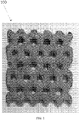
- FIG. 1 is a metal piece 100 made by the method described in this application. The method of making this metal piece is described in detail below.
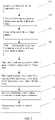
- FIG. 2 is a flowchart illustrating the steps to produce a 3D metal object in accordance with the teachings of the present invention:
- the substrate used is a non-woven carbon fiber veil such as available from Hollingsworth and Vose. Veils that have been metal coated can also be used.
- the veil or substrate is printed as described above on an inkjet printer using, for example, a HP45 thermal inkjet head with a solution primarily of de-ionized water, pyrrolidone and alcohol.
- the solution may have an anti-evaporant including glycols and pyrrolidones.
- This fluid is printed on the area of the substrate that would be part of the object, i.e., the printed area corresponds to a layer shape for the object. This is done for each layer as described in the previous applications.
- Each layer is flooded with a metal powder for example a solder powder.
- the excess powder is removed by mechanical, vacuum, vibration or compressed air or a combination of such methods. This leaves the solder powder selectively deposited.
- a metal powder for example a solder powder.
- the excess powder is removed by mechanical, vacuum, vibration or compressed air or a combination of such methods. This leaves the solder powder selectively deposited.
- One of the problems with using a metal powder in a process of this kind is that the powder oxidizes so that that when heated to its melting point the particles of the powder will not fuse together well.
- a powder flux such as rosin which acts as a reducing agent.
- a typical flux to metal powder ratio is about 50/50.
- Another method is to melt the powders in a reducing, vacuum and/or inert atmosphere oven. In this way other metals or alloys can be used, such as aluminum, steel, stainless steel, copper, brass, and titanium among others.
- liquid flux may be used as or in combination with the
- the metal powder can be mixed with a powder flux before it is deposited on the substrate. Then all the layers of the object are printed and stacked in register as described in the earlier applications. They are compressed and heated as described in the earlier applications. The heating temperature is raised to the melting point of the powder. The layers fuse together and produce a build block. After the build block is removed from the compression jig the build block is abrasively blasted and the areas where no powder adhered, that is the portions of the object that were not coated with metal, are abrasive blasted off, the uncoated carbon fiber being very fragile. What is left is a three dimensional carbon fiber metal composite of the part that was represented by the CAD model.
- FIG. 3 shows an apparatus used to selectively deposit liquid (to which powder adheres), in an illustrative implementation of this invention.
- Registration guide pins 501 are inserted through a substrate layer 503 in order to properly align the substrate layer 503.
- a solenoid valve, or inkjet head or heads 505 are used to selectively dispense liquid from a liquid reservoir 507 though a nozzle 509 unto the substrate layer 503.
- the nozzle 509 is rastered in a 2D plane 510 that is parallel to, and above, the substrate layer 503, so that the liquid is selectively deposited at desired x, y coordinates of the substrate layer 503, and not deposited in other areas of the substrate layer 503.
- a stepper motor 511 actuates two belts (not shown) that causes a support member (not shown) to move along two rails (not shown) in a direction parallel to the x axis.
- a second stepper motor (not shown) and third belt (not shown) are mounted on the support member, and are used to move a nozzle support (not shown) in a direction parallel to the y axis.
- the nozzle 509 is attached to the nozzle support. Together, the two stepper motors can move the nozzle 509 to any desired x, y coordinate above the substrate layer.
- a page wide head may also be used.
- a microprocessor 513 controls the stepper motors and the solenoid valve or inkjet head, thereby controlling when and where liquid is dispensed on the substrate layer 503.
- the stepper motors may cause the nozzle or nozzles 509 to move in other 2D patterns in the 2D plane to cause the liquid to be deposited at certain x, y coordinates.
- FIG. 2 does not show an apparatus for heating and pressing multiple layers of substrate, or for removing excess substrate. In some implementations, the substrate layer is moved to a different position before those steps occur.
- FIG. 4 is a high-level block diagram of processors, in an illustrative implementation of this invention.
- a CAD model of a desired 3D object in STL file format is created using a remote processor 601.
- This processor 601 employs software (such as Netfabb.RTM. Studio software) to create a machine-specific build file.
- the machine-specific build file is exported to a second processor 603.
- this second processor controls the operation, including movements, of: (1) an inkjet head or other device that selectively deposits liquid, (2) a vibrating trough (and/or compressed air) that spreads out the powder on the substrate and then removes the excess powder.
- this invention may be implemented with other arrangements of processors. For example, more than one remote processor and more than one onboard processor may be employed, and any of the above tasks may be handled by one or more of these different processors.
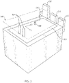
- FIG. 5 shows a compressive device 803, after a number of substrate layers (e.g., 801) have been placed in it, one on top of the other in order.
- a number of substrate layers e.g. 801
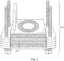
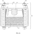
- FIG. 6 shows substrate layers being compressed in the compressive device 903. Screws 905, 907, 909, 911, plates 913, 915 and a spring 917 in the compressive device are used to exert pressure.
- FIG. 7 is a high-level block diagram of some hardware that may be used in this invention.
- One or more processors 1301 control an applicator 1303, a heating element 1305, an actuator 1307, an artificial pressure source 1309, and a stirrer in a container of liquid 1311.
- the applicator 1303 deposits powder in positive regions, but not in negative regions, of substrate layers.
- the heating element 1305 transforms the powder into matter that flows and then hardens.
- the resulting hardened material is disposed in a spatial pattern that infiltrates the substrate layers.
- the artificial pressure source 1309 may comprise a press, clamp, spring, elastic element, or other device for compressing the substrate layers.
- the stirrer may be used to stir a liquid that is used for removing excess substrate.
Description
- This application claims the benefit of
U.S. Provisional Application No. 62/256,436, filed November 17, 2015 - The present invention relates generally to three-dimensional fabrication.
- International Publication No.
WO 2014/134224 A2 (corresponding to Application No.PCT/US14/18806 ) entitled "Methods and Apparatus for Three-Dimensional Composites" (as well as Application Nos.US 61/528,537 PCT/US12/52946 ;US 13/582,939 EP20120828967 US 61/769,724 US 14/835,685 US 14/835,690 US 14/835,697 US 14/703,372 US 62/243,590 WO 2014/134224 A2 , and describes use of the technique described in the International Publication with metals. - The CBAM method described in International Publication No.
WO 2014/134224 A2 extends the range of materials that can be used with 3D printing to create three-dimensional objects. Until recently, work on this technique has concentrated on using various substrates, including carbon fiber, polymer based material and natural fibers among others and various polymers as bonding agents. This application describes the application of the CBAM method and apparatus to produce objects in metal, and in metal fiber hybrids or composites. This application also describes an article of manufacture thereof. - This approach has a number of advantages including: the ability to produce more complex geometries than conventional methods such as milling and casting; improved material properties over conventional metals; higher production rates; the elimination of complex fixturing, complex tool paths and tool changes; and, in the case of casting, the need for patterns and tools.
-
-
FIG. 1 is a metal piece made by the method described in this application. -
FIG. 2 is a flowchart illustrating the steps to produce a 3D metal object in accordance with the teachings of the present invention. -
FIG. 3 shows an apparatus used to selectively deposit liquid (to which powder adheres), in an illustrative implementation of this invention. -
FIG. 4 is a high-level block diagram of processors, in an illustrative implementation of this invention -
FIG. 5 shows a compressive device, after a number of substrate tiles (layers) have been placed in it, one on top of the other in a compressive device. The tiles are aligned by inserting registration pins of the compressive device into the registration holes of each tile, respectively. -
FIG. 6 shows a compressive device, after substrate layers with all of the "slices" of a ring torus have been inserted into it. Springs in the compressive device press the substrate layers together. -
FIG. 7 is a block diagram that shows a processor that controls multiple components of an apparatus for fabricating a 3D object. -
FIG. 1 is ametal piece 100 made by the method described in this application. The method of making this metal piece is described in detail below. -
FIG. 2 is a flowchart illustrating the steps to produce a 3D metal object in accordance with the teachings of the present invention: - 1. Generate a CAD model (Step 102) which is sliced into layers (Step 104) by using a slicer program like Netfabb as described in (International Publication No.
WO 2014/134224 A2 , ¶0055; see also US Application Nos.US 61/528,537 US 61/769,724 WO 2014/134224 A2 , ¶00121). - 2. The output of the slicer, which for example may be a bitmap file, is sent to an inkjet printer (Step 106). For each layer, the printer selectively prints a fluid onto a sheet of substrate material (Step 108) (International Publication No.
WO 2014/134224 A2 , ¶00113). The fluid may either be the bonding agent itself in liquid form; or it may be a liquid to which a powdered bonding agent adheres. Substrates can include fiberglass, high temperature glass fibers, boron fibers, or carbon fibers. - 3. If powdered bonding agent is being used, it is flooded onto the printed substrate (International Publication No.
WO 2014/134224 A2 , ¶0059). The powder adheres to the printed areas. Excess powder is removed, either by a stream of air, vacuum, vibration, or other mechanical means. - 4. The coated sheets of substrate are stacked in press or clamp (Step 110) (International Publication No.
WO 2014/134224 A2 , ¶00124), using the registration holes of each layer to align the printed portions of each sheet within the stack (International Publication No.WO 2014/134224 A2 , ¶00106). - 5. The assembled sheets are then heated and possibly compressed in an oven, to melt the bonding material and fusing the layers of substrate to form the 3D object (Step 112) (International Publication No.
WO 2014/134224 A2 , ¶00149). - 6. The unfused substrate around the 3D object is then removed (Step 114), usually by abrasive blasting material or chemical means (International Publication No.
WO 2014/134224 A2 , ¶0081). - It has been discovered that metals can be used with this technique. In one example the substrate used is a non-woven carbon fiber veil such as available from Hollingsworth and Vose. Veils that have been metal coated can also be used. The veil or substrate is printed as described above on an inkjet printer using, for example, a HP45 thermal inkjet head with a solution primarily of de-ionized water, pyrrolidone and alcohol. The solution may have an anti-evaporant including glycols and pyrrolidones. This fluid is printed on the area of the substrate that would be part of the object, i.e., the printed area corresponds to a layer shape for the object. This is done for each layer as described in the previous applications. Each layer is flooded with a metal powder for example a solder powder. The excess powder is removed by mechanical, vacuum, vibration or compressed air or a combination of such methods. This leaves the solder powder selectively deposited. One of the problems with using a metal powder in a process of this kind is that the powder oxidizes so that that when heated to its melting point the particles of the powder will not fuse together well. There are a number of solutions to this problem, one such solution is to mix the metal powder with a powder flux such as rosin which acts as a reducing agent. A typical flux to metal powder ratio is about 50/50. Another method is to melt the powders in a reducing, vacuum and/or inert atmosphere oven. In this way other metals or alloys can be used, such as aluminum, steel, stainless steel, copper, brass, and titanium among others. In addition liquid flux may be used as or in combination with the printing fluid, through selective deposition methods such as inkjet printing.
- As an example the metal powder can be mixed with a powder flux before it is deposited on the substrate. Then all the layers of the object are printed and stacked in register as described in the earlier applications. They are compressed and heated as described in the earlier applications. The heating temperature is raised to the melting point of the powder. The layers fuse together and produce a build block. After the build block is removed from the compression jig the build block is abrasively blasted and the areas where no powder adhered, that is the portions of the object that were not coated with metal, are abrasive blasted off, the uncoated carbon fiber being very fragile. What is left is a three dimensional carbon fiber metal composite of the part that was represented by the CAD model.
-
FIG. 3 shows an apparatus used to selectively deposit liquid (to which powder adheres), in an illustrative implementation of this invention. Registration guide pins 501 are inserted through a substrate layer 503 in order to properly align the substrate layer 503. A solenoid valve, or inkjet head or heads 505 are used to selectively dispense liquid from aliquid reservoir 507 though anozzle 509 unto the substrate layer 503. Thenozzle 509 is rastered in a2D plane 510 that is parallel to, and above, the substrate layer 503, so that the liquid is selectively deposited at desired x, y coordinates of the substrate layer 503, and not deposited in other areas of the substrate layer 503. To achieve this rastering, astepper motor 511 actuates two belts (not shown) that causes a support member (not shown) to move along two rails (not shown) in a direction parallel to the x axis. A second stepper motor (not shown) and third belt (not shown) are mounted on the support member, and are used to move a nozzle support (not shown) in a direction parallel to the y axis. Thenozzle 509 is attached to the nozzle support. Together, the two stepper motors can move thenozzle 509 to any desired x, y coordinate above the substrate layer. A page wide head may also be used. Amicroprocessor 513 controls the stepper motors and the solenoid valve or inkjet head, thereby controlling when and where liquid is dispensed on the substrate layer 503. Alternately, rather than rastering in a line-by-line pattern, the stepper motors may cause the nozzle ornozzles 509 to move in other 2D patterns in the 2D plane to cause the liquid to be deposited at certain x, y coordinates.FIG. 2 does not show an apparatus for heating and pressing multiple layers of substrate, or for removing excess substrate. In some implementations, the substrate layer is moved to a different position before those steps occur. -
FIG. 4 is a high-level block diagram of processors, in an illustrative implementation of this invention. A CAD model of a desired 3D object in STL file format is created using a remote processor 601. This processor 601 employs software (such as Netfabb.RTM. Studio software) to create a machine-specific build file. The machine-specific build file is exported to a second processor 603. Depending on the particular implementation, this second processor controls the operation, including movements, of: (1) an inkjet head or other device that selectively deposits liquid, (2) a vibrating trough (and/or compressed air) that spreads out the powder on the substrate and then removes the excess powder. Alternately, this invention may be implemented with other arrangements of processors. For example, more than one remote processor and more than one onboard processor may be employed, and any of the above tasks may be handled by one or more of these different processors. -
FIG. 5 shows acompressive device 803, after a number of substrate layers (e.g., 801) have been placed in it, one on top of the other in order. -
FIG. 6 shows substrate layers being compressed in the compressive device 903. Screws 905, 907, 909, 911,plates 913, 915 and aspring 917 in the compressive device are used to exert pressure. -
FIG. 7 is a high-level block diagram of some hardware that may be used in this invention. One ormore processors 1301 control anapplicator 1303, aheating element 1305, anactuator 1307, an artificial pressure source 1309, and a stirrer in a container of liquid 1311. Theapplicator 1303 deposits powder in positive regions, but not in negative regions, of substrate layers. Theheating element 1305 transforms the powder into matter that flows and then hardens. The resulting hardened material is disposed in a spatial pattern that infiltrates the substrate layers. The artificial pressure source 1309 may comprise a press, clamp, spring, elastic element, or other device for compressing the substrate layers. The stirrer may be used to stir a liquid that is used for removing excess substrate.
Claims (13)
- A method for producing an object, comprising:taking a file of layers of a 3D object;for each layer, printing a fluid selectively onto a sheet of substrate material, wherein the substrate material comprises fiberglass, high temperature glass fibers, boron fibers, or carbon fibers;flooding onto the substrate a powdered metal which adheres to the selectively printed fluid;removing excess powder; andheating and compressing a plurality of sheets in stacked registration to melt the powdered metal and fuse the layers of substrate.
- The method of claim 1, further comprising removing unfused material of the substrate sheets.
- The method of claim 1, wherein registration holes are used to stack the sheets in registration.
- The method of claim 1, wherein the powdered metal is a solder powder.
- The method of claim 1, wherein the powdered metal is aluminium, steel, copper, brass or titanium.
- The method of claim 1, wherein the excess powder is removed by a stream of air, vacuum or vibration.
- The method of claim 1, wherein the powdered metal is mixed with a powder flux acting as a reducing agent.
- The method of claim 1, wherein the powdered metal is melted in a reducing atmosphere, vacuum, or inert atmosphere oven.
- The method of claim 1, wherein the heating temperature is raised to the melting point of the powder.
- The method of claim 2, wherein unfused substrate is removed by air- blasting with an abrasive material or chemical means.
- The method of claim 1, wherein the substrate material is a non-woven carbon fiber veil.
- The method of claim 1, wherein the substrate material is a metal coated veil.
- The method of claim 1, wherein the printing is done using an inkjet head with a solution primarily of de-ionized water, pyrrolidone, and alcohol.
Applications Claiming Priority (2)
| Application Number | Priority Date | Filing Date | Title |
|---|---|---|---|
| US201562256436P | 2015-11-17 | 2015-11-17 | |
| PCT/US2016/062356 WO2017087572A1 (en) | 2015-11-17 | 2016-11-16 | Apparatus and process for producing additive manufactured metal matrix composites and article of manufacture thereof |
Publications (3)
| Publication Number | Publication Date |
|---|---|
| EP3377249A1 EP3377249A1 (en) | 2018-09-26 |
| EP3377249A4 EP3377249A4 (en) | 2019-12-11 |
| EP3377249B1 true EP3377249B1 (en) | 2022-11-02 |
Family
ID=58717782
Family Applications (1)
| Application Number | Title | Priority Date | Filing Date |
|---|---|---|---|
| EP16867076.8A Active EP3377249B1 (en) | 2015-11-17 | 2016-11-16 | Process for producing additive manufactured metal matrix composites |
Country Status (6)
| Country | Link |
|---|---|
| US (4) | US20170291223A1 (en) |
| EP (1) | EP3377249B1 (en) |
| JP (3) | JP2018537587A (en) |
| KR (1) | KR102597223B1 (en) |
| CN (1) | CN108472727A (en) |
| WO (1) | WO2017087572A1 (en) |
Families Citing this family (25)
| Publication number | Priority date | Publication date | Assignee | Title |
|---|---|---|---|---|
| US9833949B2 (en) | 2011-08-29 | 2017-12-05 | Impossible Objects, Inc. | Apparatus for fabricating three-dimensional printed composites |
| US10343243B2 (en) | 2013-02-26 | 2019-07-09 | Robert Swartz | Methods and apparatus for construction of machine tools |
| KR20190019899A (en) * | 2016-02-12 | 2019-02-27 | 임파서블 오브젝츠 엘엘씨 | Automated composite-based lamination processing method and apparatus |
| WO2019110844A1 (en) * | 2017-12-08 | 2019-06-13 | Oerlikon Am Gmbh | Assisted fused deposition modeling |
| DE102017223259A1 (en) | 2017-12-19 | 2019-06-19 | MTU Aero Engines AG | METHOD AND DEVICE FOR CLEANING PARTIALLY MANUFACTURED COMPONENTS DURING GENERATIVE PRODUCTION |
| CN108165961A (en) * | 2018-01-17 | 2018-06-15 | 华南理工大学 | A kind of 3D printer and its operation method based on liquid solid chemical reaction deposition |
| US11731352B2 (en) | 2019-03-29 | 2023-08-22 | Xerox Corporation | Apparatus and method for fabricating multi-polymer composite structures |
| US11104077B2 (en) | 2019-03-29 | 2021-08-31 | Xerox Corporation | Composite-based additive manufacturing (CBAM) image quality (IQ) verification and rejection handling |
| US11130291B2 (en) | 2019-03-29 | 2021-09-28 | Xerox Corporation | Composite-based additive manufacturing (CBAM) use of gravity for excess polymer removal |
| US10920351B2 (en) | 2019-03-29 | 2021-02-16 | Xerox Corporation | Sewing method and apparatus to increase 3D object strength |
| US11117325B2 (en) | 2019-03-29 | 2021-09-14 | Xerox Corporation | Composite-based additive manufacturing (CBAM) augmented reality assisted sand blasting |
| US11485110B2 (en) | 2019-03-29 | 2022-11-01 | Xerox Corporation | Cross layer fiber entanglement to increase strength of 3D part |
| US11046002B2 (en) | 2019-03-29 | 2021-06-29 | Xerox Corporation | Wetting agent additive for an in-line quality check of composite-based additive manufacturing (CBAM) substrates |
| US11214000B2 (en) | 2019-04-03 | 2022-01-04 | Xerox Corporation | Apparatus and method for fabricating multi-sided printed composite sheet structures |
| US11312049B2 (en) | 2019-04-03 | 2022-04-26 | Xerox Corporation | Additive manufacturing system for halftone colored 3D objects |
| US11679601B2 (en) | 2019-05-16 | 2023-06-20 | Impossible Objects, Inc. | Holdown process and system for platen |
| US11318671B2 (en) | 2019-05-21 | 2022-05-03 | Xerox Corporation | System and method for sheeting and stacking 3D composite printed sheets |
| US11518092B2 (en) | 2019-06-19 | 2022-12-06 | Xerox Corporation | Patterned pre-stop for finishing additive manufactured 3D objects |
| WO2021046660A1 (en) * | 2019-09-13 | 2021-03-18 | Christie Remy Maillet Jorge Andres | System and method for designing and manufacturing objects having an optimised free-form with novel composite materials and the resulting object |
| US11904532B2 (en) | 2020-01-23 | 2024-02-20 | Impossible Objects, Inc. | Carbon fiber sheet separation with flickers for 3-dimensional printing |
| US11806931B2 (en) | 2020-01-23 | 2023-11-07 | Impossible Objects, Inc. | Bulk ink bags for 3-dimensional printing |
| US11413821B2 (en) | 2020-01-23 | 2022-08-16 | Impossible Objects, Inc. | Powder refill system for 3-dimensional printing |
| WO2021151047A1 (en) | 2020-01-23 | 2021-07-29 | Impossible Objects, Inc. | Camera-based monitoring system for 3-dimensional printing |
| CN113059799B (en) * | 2021-02-19 | 2023-05-05 | 浙江工贸职业技术学院 | 3D object printing method |
| US11938537B2 (en) | 2022-08-01 | 2024-03-26 | Xerox Corporation | System and method for high throughput additive manufacturing of sintered parts with low anisotropy |
Family Cites Families (24)
| Publication number | Priority date | Publication date | Assignee | Title |
|---|---|---|---|---|
| US5637175A (en) * | 1988-10-05 | 1997-06-10 | Helisys Corporation | Apparatus for forming an integral object from laminations |
| US5204055A (en) * | 1989-12-08 | 1993-04-20 | Massachusetts Institute Of Technology | Three-dimensional printing techniques |
| JPH08192468A (en) * | 1995-01-19 | 1996-07-30 | Hitachi Ltd | Method and apparatus for producing three-dimensional model |
| US6814823B1 (en) * | 1999-09-16 | 2004-11-09 | Solidica, Inc. | Object consolidation through sequential material deposition |
| US6780368B2 (en) * | 2001-04-10 | 2004-08-24 | Nanotek Instruments, Inc. | Layer manufacturing of a multi-material or multi-color 3-D object using electrostatic imaging and lamination |
| GB0112675D0 (en) * | 2001-05-24 | 2001-07-18 | Vantico Ltd | Three-dimensional structured printing |
| AUPR597401A0 (en) * | 2001-06-27 | 2001-07-19 | Summerfield, Martin Raymond | Ceramic powder transfer process |
| JP4224438B2 (en) * | 2004-07-16 | 2009-02-12 | 日信工業株式会社 | Method for producing carbon fiber composite metal material |
| US8267683B2 (en) * | 2005-07-27 | 2012-09-18 | Shofu Inc. | Apparatus for forming layered object |
| US20080032099A1 (en) * | 2006-07-20 | 2008-02-07 | Elmer's Products, Inc. | Heat activated art mounting sheet |
| CN100570268C (en) * | 2006-09-27 | 2009-12-16 | 北京航空航天大学 | Fibre-reinforced metal/ceramic laminated composite material prevention plate |
| CN101417339B (en) * | 2008-12-05 | 2010-09-08 | 西北有色金属研究院 | Preparation method of ultra light porous metal fiber sandwich board |
| CN101927346A (en) * | 2010-09-09 | 2010-12-29 | 上海交通大学医学院附属第九人民医院 | Three-dimensional printing technology based method for forming medical porous pure titanium implant |
| EP2776233B1 (en) * | 2011-08-29 | 2017-12-27 | Impossible Objects, Inc. | Methods and apparatus for 3d fabrication |
| US9776376B2 (en) * | 2011-08-29 | 2017-10-03 | Impossible Objects, LLC | Methods and apparatus for three-dimensional printed composites based on flattened substrate sheets |
| US10190220B2 (en) | 2013-01-31 | 2019-01-29 | Siemens Energy, Inc. | Functional based repair of superalloy components |
| EP2961585B1 (en) * | 2013-02-26 | 2020-05-27 | Impossible Objects LLC | Methods and apparatus for three-dimensional printed composites |
| DE102013010160A1 (en) * | 2013-06-19 | 2015-01-08 | Hueck Rheinische Gmbh | Process for producing a material plate by means of a press plate or endless belt, and press plate or endless belt and material plate |
| CA2915409A1 (en) * | 2013-06-24 | 2014-12-31 | President And Fellows Of Harvard College | Printed three-dimensional (3d) functional part and method of making |
| CN103397284B (en) * | 2013-07-29 | 2014-06-04 | 太原理工大学 | Preparation method of carbon fiber strengthened aluminum-base-layer-shaped composite board |
| JP2015196267A (en) * | 2014-03-31 | 2015-11-09 | 株式会社東芝 | Method and apparatus for production of laminated molding and slurry |
| CN106804106A (en) * | 2014-05-04 | 2017-06-06 | 亦欧普莱克斯公司 | Many material three-dimensional printers |
| CN104399986B (en) * | 2014-05-31 | 2016-09-07 | 福州大学 | A kind of 3D Method of printing for preparing base metal and alloy components thereof |
| CN104150915B (en) * | 2014-08-06 | 2015-08-26 | 西安交通大学 | A kind of powder 3D Method of printing based on water-based inorganic binding agent |
-
2016
- 2016-11-16 WO PCT/US2016/062356 patent/WO2017087572A1/en active Application Filing
- 2016-11-16 JP JP2018526517A patent/JP2018537587A/en active Pending
- 2016-11-16 CN CN201680078140.8A patent/CN108472727A/en active Pending
- 2016-11-16 KR KR1020187017121A patent/KR102597223B1/en active IP Right Grant
- 2016-11-16 EP EP16867076.8A patent/EP3377249B1/en active Active
-
2017
- 2017-06-23 US US15/631,634 patent/US20170291223A1/en not_active Abandoned
-
2018
- 2018-11-19 US US16/195,362 patent/US11173546B2/en active Active
-
2021
- 2021-07-21 JP JP2021120674A patent/JP2021179014A/en active Pending
- 2021-11-16 US US17/455,118 patent/US11674207B2/en active Active
-
2023
- 2023-06-06 JP JP2023093292A patent/JP2023113828A/en active Pending
- 2023-06-08 US US18/331,566 patent/US20230313352A1/en active Pending
Also Published As
| Publication number | Publication date |
|---|---|
| EP3377249A4 (en) | 2019-12-11 |
| US20230313352A1 (en) | 2023-10-05 |
| US20170291223A1 (en) | 2017-10-12 |
| US20190084046A1 (en) | 2019-03-21 |
| US11173546B2 (en) | 2021-11-16 |
| CN108472727A (en) | 2018-08-31 |
| JP2023113828A (en) | 2023-08-16 |
| EP3377249A1 (en) | 2018-09-26 |
| JP2018537587A (en) | 2018-12-20 |
| KR102597223B1 (en) | 2023-11-03 |
| JP2021179014A (en) | 2021-11-18 |
| US11674207B2 (en) | 2023-06-13 |
| WO2017087572A1 (en) | 2017-05-26 |
| US20220072611A1 (en) | 2022-03-10 |
| KR20180097550A (en) | 2018-08-31 |
Similar Documents
| Publication | Publication Date | Title |
|---|---|---|
| US11674207B2 (en) | Apparatus and process for producing additive manufactured metal matrix composites and article of manufacture thereof | |
| US11370166B2 (en) | Methods and apparatus for three-dimensional printed composites based on folded substrate sheets | |
| US10377106B2 (en) | Methods and apparatus for three-dimensional printed composites based on flattened substrate sheets | |
| EP0529816B1 (en) | Method and apparatus for fabrication of three-dimensional articles by weld deposition | |
| EP2961585B1 (en) | Methods and apparatus for three-dimensional printed composites | |
| JP3021668B2 (en) | Free-form-giving article by layer deposition | |
| US8575513B2 (en) | Rapid prototyping of ceramic articles | |
| US20200198232A1 (en) | Three-dimensional forming apparatus and three-dimensional forming method | |
| EP0490546B1 (en) | Method and apparatus for fabrication of three-dimensional articles by thermal spray deposition | |
| CN106001568B (en) | A kind of functionally gradient material (FGM) metal die 3D printing integral preparation method | |
| US5301415A (en) | Method for fabrication of three-dimensional articles | |
| US20180250739A1 (en) | Additive manufacturing method and apparatus | |
| JP7042530B2 (en) | 3D printer and its operation method | |
| EP3717208B1 (en) | Additive manufacturing apparatus and related process | |
| CN106735224A (en) | A kind of porous metal structure part hot melt drop printing deposition method for preparing and device | |
| EP0554033B1 (en) | Method for fabrication of three-dimensional articles | |
| EP3917448A1 (en) | Three-dimensional printed composites using substrates with sodium silicate binder | |
| US20060290772A1 (en) | Method of manufacturing rapid prototyping workpiece by using laser transfer printing technology | |
| JP2015124441A (en) | Metal powder sintering body manufacturing device and metal powder sintering body manufacturing method | |
| Sirinterlikci et al. | 3D Printing Processes and Associated Materials | |
| Harris et al. | United States Patent m |
Legal Events
| Date | Code | Title | Description |
|---|---|---|---|
| STAA | Information on the status of an ep patent application or granted ep patent |
Free format text: STATUS: THE INTERNATIONAL PUBLICATION HAS BEEN MADE |
|
| PUAI | Public reference made under article 153(3) epc to a published international application that has entered the european phase |
Free format text: ORIGINAL CODE: 0009012 |
|
| STAA | Information on the status of an ep patent application or granted ep patent |
Free format text: STATUS: REQUEST FOR EXAMINATION WAS MADE |
|
| 17P | Request for examination filed |
Effective date: 20180615 |
|
| AK | Designated contracting states |
Kind code of ref document: A1 Designated state(s): AL AT BE BG CH CY CZ DE DK EE ES FI FR GB GR HR HU IE IS IT LI LT LU LV MC MK MT NL NO PL PT RO RS SE SI SK SM TR |
|
| AX | Request for extension of the european patent |
Extension state: BA ME |
|
| DAV | Request for validation of the european patent (deleted) | ||
| DAX | Request for extension of the european patent (deleted) | ||
| A4 | Supplementary search report drawn up and despatched |
Effective date: 20191111 |
|
| RIC1 | Information provided on ipc code assigned before grant |
Ipc: B22F 7/04 20060101ALI20191105BHEP Ipc: B29C 64/165 20170101ALI20191105BHEP Ipc: B22F 3/00 20060101ALI20191105BHEP Ipc: C22C 49/14 20060101ALI20191105BHEP Ipc: B29C 67/02 20170101ALI20191105BHEP Ipc: B29C 67/24 20060101ALI20191105BHEP Ipc: B29C 64/112 20170101ALN20191105BHEP Ipc: C22C 47/02 20060101AFI20191105BHEP Ipc: C22C 47/06 20060101ALI20191105BHEP Ipc: B29C 64/205 20170101ALI20191105BHEP Ipc: B33Y 10/00 20150101ALI20191105BHEP Ipc: B33Y 40/00 20150101ALN20191105BHEP Ipc: B33Y 30/00 20150101ALI20191105BHEP Ipc: B29C 67/00 20170101ALI20191105BHEP Ipc: C22C 47/20 20060101ALI20191105BHEP Ipc: B29C 64/194 20170101ALI20191105BHEP |
|
| STAA | Information on the status of an ep patent application or granted ep patent |
Free format text: STATUS: EXAMINATION IS IN PROGRESS |
|
| 17Q | First examination report despatched |
Effective date: 20201001 |
|
| STAA | Information on the status of an ep patent application or granted ep patent |
Free format text: STATUS: EXAMINATION IS IN PROGRESS |
|
| REG | Reference to a national code |
Ref country code: DE Ref legal event code: R079 Ref document number: 602016076129 Country of ref document: DE Free format text: PREVIOUS MAIN CLASS: B22F0003000000 Ipc: C22C0047020000 |
|
| GRAP | Despatch of communication of intention to grant a patent |
Free format text: ORIGINAL CODE: EPIDOSNIGR1 |
|
| STAA | Information on the status of an ep patent application or granted ep patent |
Free format text: STATUS: GRANT OF PATENT IS INTENDED |
|
| RIC1 | Information provided on ipc code assigned before grant |
Ipc: B29C 64/112 20170101ALN20220211BHEP Ipc: B33Y 40/00 20150101ALN20220211BHEP Ipc: B22F 10/20 20210101ALI20220211BHEP Ipc: B22F 12/00 20210101ALI20220211BHEP Ipc: B22F 10/66 20210101ALI20220211BHEP Ipc: B29C 64/194 20170101ALI20220211BHEP Ipc: B29C 64/205 20170101ALI20220211BHEP Ipc: B29C 64/165 20170101ALI20220211BHEP Ipc: B29C 67/24 20060101ALI20220211BHEP Ipc: B29C 67/02 20170101ALI20220211BHEP Ipc: B29C 67/00 20170101ALI20220211BHEP Ipc: B22F 7/04 20060101ALI20220211BHEP Ipc: B22F 3/00 20060101ALI20220211BHEP Ipc: B33Y 30/00 20150101ALI20220211BHEP Ipc: B33Y 10/00 20150101ALI20220211BHEP Ipc: C22C 49/14 20060101ALI20220211BHEP Ipc: C22C 47/20 20060101ALI20220211BHEP Ipc: C22C 47/06 20060101ALI20220211BHEP Ipc: C22C 47/02 20060101AFI20220211BHEP |
|
| INTG | Intention to grant announced |
Effective date: 20220310 |
|
| GRAS | Grant fee paid |
Free format text: ORIGINAL CODE: EPIDOSNIGR3 |
|
| GRAA | (expected) grant |
Free format text: ORIGINAL CODE: 0009210 |
|
| STAA | Information on the status of an ep patent application or granted ep patent |
Free format text: STATUS: THE PATENT HAS BEEN GRANTED |
|
| AK | Designated contracting states |
Kind code of ref document: B1 Designated state(s): AL AT BE BG CH CY CZ DE DK EE ES FI FR GB GR HR HU IE IS IT LI LT LU LV MC MK MT NL NO PL PT RO RS SE SI SK SM TR |
|
| RAP1 | Party data changed (applicant data changed or rights of an application transferred) |
Owner name: IMPOSSIBLE OBJECTS, INC. |
|
| REG | Reference to a national code |
Ref country code: GB Ref legal event code: FG4D |
|
| REG | Reference to a national code |
Ref country code: CH Ref legal event code: EP Ref country code: AT Ref legal event code: REF Ref document number: 1528787 Country of ref document: AT Kind code of ref document: T Effective date: 20221115 |
|
| REG | Reference to a national code |
Ref country code: DE Ref legal event code: R096 Ref document number: 602016076129 Country of ref document: DE |
|
| REG | Reference to a national code |
Ref country code: IE Ref legal event code: FG4D |
|
| REG | Reference to a national code |
Ref country code: LT Ref legal event code: MG9D |
|
| REG | Reference to a national code |
Ref country code: NL Ref legal event code: MP Effective date: 20221102 |
|
| REG | Reference to a national code |
Ref country code: AT Ref legal event code: MK05 Ref document number: 1528787 Country of ref document: AT Kind code of ref document: T Effective date: 20221102 |
|
| PG25 | Lapsed in a contracting state [announced via postgrant information from national office to epo] |
Ref country code: SE Free format text: LAPSE BECAUSE OF FAILURE TO SUBMIT A TRANSLATION OF THE DESCRIPTION OR TO PAY THE FEE WITHIN THE PRESCRIBED TIME-LIMIT Effective date: 20221102 Ref country code: PT Free format text: LAPSE BECAUSE OF FAILURE TO SUBMIT A TRANSLATION OF THE DESCRIPTION OR TO PAY THE FEE WITHIN THE PRESCRIBED TIME-LIMIT Effective date: 20230302 Ref country code: NO Free format text: LAPSE BECAUSE OF FAILURE TO SUBMIT A TRANSLATION OF THE DESCRIPTION OR TO PAY THE FEE WITHIN THE PRESCRIBED TIME-LIMIT Effective date: 20230202 Ref country code: LT Free format text: LAPSE BECAUSE OF FAILURE TO SUBMIT A TRANSLATION OF THE DESCRIPTION OR TO PAY THE FEE WITHIN THE PRESCRIBED TIME-LIMIT Effective date: 20221102 Ref country code: FI Free format text: LAPSE BECAUSE OF FAILURE TO SUBMIT A TRANSLATION OF THE DESCRIPTION OR TO PAY THE FEE WITHIN THE PRESCRIBED TIME-LIMIT Effective date: 20221102 Ref country code: ES Free format text: LAPSE BECAUSE OF FAILURE TO SUBMIT A TRANSLATION OF THE DESCRIPTION OR TO PAY THE FEE WITHIN THE PRESCRIBED TIME-LIMIT Effective date: 20221102 Ref country code: AT Free format text: LAPSE BECAUSE OF FAILURE TO SUBMIT A TRANSLATION OF THE DESCRIPTION OR TO PAY THE FEE WITHIN THE PRESCRIBED TIME-LIMIT Effective date: 20221102 |
|
| PG25 | Lapsed in a contracting state [announced via postgrant information from national office to epo] |
Ref country code: RS Free format text: LAPSE BECAUSE OF FAILURE TO SUBMIT A TRANSLATION OF THE DESCRIPTION OR TO PAY THE FEE WITHIN THE PRESCRIBED TIME-LIMIT Effective date: 20221102 Ref country code: PL Free format text: LAPSE BECAUSE OF FAILURE TO SUBMIT A TRANSLATION OF THE DESCRIPTION OR TO PAY THE FEE WITHIN THE PRESCRIBED TIME-LIMIT Effective date: 20221102 Ref country code: LV Free format text: LAPSE BECAUSE OF FAILURE TO SUBMIT A TRANSLATION OF THE DESCRIPTION OR TO PAY THE FEE WITHIN THE PRESCRIBED TIME-LIMIT Effective date: 20221102 Ref country code: IS Free format text: LAPSE BECAUSE OF FAILURE TO SUBMIT A TRANSLATION OF THE DESCRIPTION OR TO PAY THE FEE WITHIN THE PRESCRIBED TIME-LIMIT Effective date: 20230302 Ref country code: HR Free format text: LAPSE BECAUSE OF FAILURE TO SUBMIT A TRANSLATION OF THE DESCRIPTION OR TO PAY THE FEE WITHIN THE PRESCRIBED TIME-LIMIT Effective date: 20221102 Ref country code: GR Free format text: LAPSE BECAUSE OF FAILURE TO SUBMIT A TRANSLATION OF THE DESCRIPTION OR TO PAY THE FEE WITHIN THE PRESCRIBED TIME-LIMIT Effective date: 20230203 |
|
| PG25 | Lapsed in a contracting state [announced via postgrant information from national office to epo] |
Ref country code: NL Free format text: LAPSE BECAUSE OF FAILURE TO SUBMIT A TRANSLATION OF THE DESCRIPTION OR TO PAY THE FEE WITHIN THE PRESCRIBED TIME-LIMIT Effective date: 20221102 |
|
| P01 | Opt-out of the competence of the unified patent court (upc) registered |
Effective date: 20230530 |
|
| REG | Reference to a national code |
Ref country code: BE Ref legal event code: MM Effective date: 20221130 |
|
| PG25 | Lapsed in a contracting state [announced via postgrant information from national office to epo] |
Ref country code: SM Free format text: LAPSE BECAUSE OF FAILURE TO SUBMIT A TRANSLATION OF THE DESCRIPTION OR TO PAY THE FEE WITHIN THE PRESCRIBED TIME-LIMIT Effective date: 20221102 Ref country code: RO Free format text: LAPSE BECAUSE OF FAILURE TO SUBMIT A TRANSLATION OF THE DESCRIPTION OR TO PAY THE FEE WITHIN THE PRESCRIBED TIME-LIMIT Effective date: 20221102 Ref country code: EE Free format text: LAPSE BECAUSE OF FAILURE TO SUBMIT A TRANSLATION OF THE DESCRIPTION OR TO PAY THE FEE WITHIN THE PRESCRIBED TIME-LIMIT Effective date: 20221102 Ref country code: DK Free format text: LAPSE BECAUSE OF FAILURE TO SUBMIT A TRANSLATION OF THE DESCRIPTION OR TO PAY THE FEE WITHIN THE PRESCRIBED TIME-LIMIT Effective date: 20221102 Ref country code: CZ Free format text: LAPSE BECAUSE OF FAILURE TO SUBMIT A TRANSLATION OF THE DESCRIPTION OR TO PAY THE FEE WITHIN THE PRESCRIBED TIME-LIMIT Effective date: 20221102 |
|
| REG | Reference to a national code |
Ref country code: DE Ref legal event code: R097 Ref document number: 602016076129 Country of ref document: DE |
|
| PG25 | Lapsed in a contracting state [announced via postgrant information from national office to epo] |
Ref country code: SK Free format text: LAPSE BECAUSE OF FAILURE TO SUBMIT A TRANSLATION OF THE DESCRIPTION OR TO PAY THE FEE WITHIN THE PRESCRIBED TIME-LIMIT Effective date: 20221102 Ref country code: LU Free format text: LAPSE BECAUSE OF NON-PAYMENT OF DUE FEES Effective date: 20221116 Ref country code: AL Free format text: LAPSE BECAUSE OF FAILURE TO SUBMIT A TRANSLATION OF THE DESCRIPTION OR TO PAY THE FEE WITHIN THE PRESCRIBED TIME-LIMIT Effective date: 20221102 |
|
| PLBE | No opposition filed within time limit |
Free format text: ORIGINAL CODE: 0009261 |
|
| STAA | Information on the status of an ep patent application or granted ep patent |
Free format text: STATUS: NO OPPOSITION FILED WITHIN TIME LIMIT |
|
| 26N | No opposition filed |
Effective date: 20230803 |
|
| PG25 | Lapsed in a contracting state [announced via postgrant information from national office to epo] |
Ref country code: IE Free format text: LAPSE BECAUSE OF NON-PAYMENT OF DUE FEES Effective date: 20221116 |
|
| PGFP | Annual fee paid to national office [announced via postgrant information from national office to epo] |
Ref country code: GB Payment date: 20230908 Year of fee payment: 8 |
|
| PG25 | Lapsed in a contracting state [announced via postgrant information from national office to epo] |
Ref country code: SI Free format text: LAPSE BECAUSE OF FAILURE TO SUBMIT A TRANSLATION OF THE DESCRIPTION OR TO PAY THE FEE WITHIN THE PRESCRIBED TIME-LIMIT Effective date: 20221102 Ref country code: BE Free format text: LAPSE BECAUSE OF NON-PAYMENT OF DUE FEES Effective date: 20221130 |
|
| PGFP | Annual fee paid to national office [announced via postgrant information from national office to epo] |
Ref country code: FR Payment date: 20231122 Year of fee payment: 8 Ref country code: DE Payment date: 20231120 Year of fee payment: 8 Ref country code: CH Payment date: 20231201 Year of fee payment: 8 |
|
| PG25 | Lapsed in a contracting state [announced via postgrant information from national office to epo] |
Ref country code: HU Free format text: LAPSE BECAUSE OF FAILURE TO SUBMIT A TRANSLATION OF THE DESCRIPTION OR TO PAY THE FEE WITHIN THE PRESCRIBED TIME-LIMIT; INVALID AB INITIO Effective date: 20161116 |