EP3377018B1 - Patient handling apparatus and method - Google Patents
Patient handling apparatus and method Download PDFInfo
- Publication number
- EP3377018B1 EP3377018B1 EP16710284.7A EP16710284A EP3377018B1 EP 3377018 B1 EP3377018 B1 EP 3377018B1 EP 16710284 A EP16710284 A EP 16710284A EP 3377018 B1 EP3377018 B1 EP 3377018B1
- Authority
- EP
- European Patent Office
- Prior art keywords
- cradle
- patient
- section
- inflated
- seat
- Prior art date
- Legal status (The legal status is an assumption and is not a legal conclusion. Google has not performed a legal analysis and makes no representation as to the accuracy of the status listed.)
- Active
Links
Images


Classifications
-
- A—HUMAN NECESSITIES
- A61—MEDICAL OR VETERINARY SCIENCE; HYGIENE
- A61G—TRANSPORT, PERSONAL CONVEYANCES, OR ACCOMMODATION SPECIALLY ADAPTED FOR PATIENTS OR DISABLED PERSONS; OPERATING TABLES OR CHAIRS; CHAIRS FOR DENTISTRY; FUNERAL DEVICES
- A61G7/00—Beds specially adapted for nursing; Devices for lifting patients or disabled persons
- A61G7/10—Devices for lifting patients or disabled persons, e.g. special adaptations of hoists thereto
- A61G7/1049—Attachment, suspending or supporting means for patients
- A61G7/1059—Seats
-
- A—HUMAN NECESSITIES
- A61—MEDICAL OR VETERINARY SCIENCE; HYGIENE
- A61G—TRANSPORT, PERSONAL CONVEYANCES, OR ACCOMMODATION SPECIALLY ADAPTED FOR PATIENTS OR DISABLED PERSONS; OPERATING TABLES OR CHAIRS; CHAIRS FOR DENTISTRY; FUNERAL DEVICES
- A61G5/00—Chairs or personal conveyances specially adapted for patients or disabled persons, e.g. wheelchairs
- A61G5/10—Parts, details or accessories
- A61G5/1002—Parts, details or accessories with toilet facilities
-
- A—HUMAN NECESSITIES
- A61—MEDICAL OR VETERINARY SCIENCE; HYGIENE
- A61G—TRANSPORT, PERSONAL CONVEYANCES, OR ACCOMMODATION SPECIALLY ADAPTED FOR PATIENTS OR DISABLED PERSONS; OPERATING TABLES OR CHAIRS; CHAIRS FOR DENTISTRY; FUNERAL DEVICES
- A61G5/00—Chairs or personal conveyances specially adapted for patients or disabled persons, e.g. wheelchairs
- A61G5/10—Parts, details or accessories
- A61G5/1005—Wheelchairs having brakes
- A61G5/1013—Wheelchairs having brakes engaging the wheel
- A61G5/1018—Wheelchairs having brakes engaging the wheel on the running surface
-
- A—HUMAN NECESSITIES
- A61—MEDICAL OR VETERINARY SCIENCE; HYGIENE
- A61G—TRANSPORT, PERSONAL CONVEYANCES, OR ACCOMMODATION SPECIALLY ADAPTED FOR PATIENTS OR DISABLED PERSONS; OPERATING TABLES OR CHAIRS; CHAIRS FOR DENTISTRY; FUNERAL DEVICES
- A61G5/00—Chairs or personal conveyances specially adapted for patients or disabled persons, e.g. wheelchairs
- A61G5/10—Parts, details or accessories
- A61G5/1005—Wheelchairs having brakes
- A61G5/1037—Wheelchairs having brakes manipulated by assisting person
-
- A—HUMAN NECESSITIES
- A61—MEDICAL OR VETERINARY SCIENCE; HYGIENE
- A61G—TRANSPORT, PERSONAL CONVEYANCES, OR ACCOMMODATION SPECIALLY ADAPTED FOR PATIENTS OR DISABLED PERSONS; OPERATING TABLES OR CHAIRS; CHAIRS FOR DENTISTRY; FUNERAL DEVICES
- A61G5/00—Chairs or personal conveyances specially adapted for patients or disabled persons, e.g. wheelchairs
- A61G5/10—Parts, details or accessories
- A61G5/1056—Arrangements for adjusting the seat
- A61G5/1059—Arrangements for adjusting the seat adjusting the height of the seat
-
- A—HUMAN NECESSITIES
- A61—MEDICAL OR VETERINARY SCIENCE; HYGIENE
- A61G—TRANSPORT, PERSONAL CONVEYANCES, OR ACCOMMODATION SPECIALLY ADAPTED FOR PATIENTS OR DISABLED PERSONS; OPERATING TABLES OR CHAIRS; CHAIRS FOR DENTISTRY; FUNERAL DEVICES
- A61G5/00—Chairs or personal conveyances specially adapted for patients or disabled persons, e.g. wheelchairs
- A61G5/10—Parts, details or accessories
- A61G5/1091—Cushions, seats or abduction devices
-
- A—HUMAN NECESSITIES
- A61—MEDICAL OR VETERINARY SCIENCE; HYGIENE
- A61G—TRANSPORT, PERSONAL CONVEYANCES, OR ACCOMMODATION SPECIALLY ADAPTED FOR PATIENTS OR DISABLED PERSONS; OPERATING TABLES OR CHAIRS; CHAIRS FOR DENTISTRY; FUNERAL DEVICES
- A61G5/00—Chairs or personal conveyances specially adapted for patients or disabled persons, e.g. wheelchairs
- A61G5/10—Parts, details or accessories
- A61G5/12—Rests specially adapted therefor, e.g. for the head or the feet
- A61G5/122—Rests specially adapted therefor, e.g. for the head or the feet for the back
-
- A—HUMAN NECESSITIES
- A61—MEDICAL OR VETERINARY SCIENCE; HYGIENE
- A61G—TRANSPORT, PERSONAL CONVEYANCES, OR ACCOMMODATION SPECIALLY ADAPTED FOR PATIENTS OR DISABLED PERSONS; OPERATING TABLES OR CHAIRS; CHAIRS FOR DENTISTRY; FUNERAL DEVICES
- A61G5/00—Chairs or personal conveyances specially adapted for patients or disabled persons, e.g. wheelchairs
- A61G5/10—Parts, details or accessories
- A61G5/12—Rests specially adapted therefor, e.g. for the head or the feet
- A61G5/127—Rests specially adapted therefor, e.g. for the head or the feet for lower legs
-
- A—HUMAN NECESSITIES
- A61—MEDICAL OR VETERINARY SCIENCE; HYGIENE
- A61G—TRANSPORT, PERSONAL CONVEYANCES, OR ACCOMMODATION SPECIALLY ADAPTED FOR PATIENTS OR DISABLED PERSONS; OPERATING TABLES OR CHAIRS; CHAIRS FOR DENTISTRY; FUNERAL DEVICES
- A61G7/00—Beds specially adapted for nursing; Devices for lifting patients or disabled persons
- A61G7/02—Beds specially adapted for nursing; Devices for lifting patients or disabled persons with toilet conveniences, or specially adapted for use with toilets
-
- A—HUMAN NECESSITIES
- A61—MEDICAL OR VETERINARY SCIENCE; HYGIENE
- A61G—TRANSPORT, PERSONAL CONVEYANCES, OR ACCOMMODATION SPECIALLY ADAPTED FOR PATIENTS OR DISABLED PERSONS; OPERATING TABLES OR CHAIRS; CHAIRS FOR DENTISTRY; FUNERAL DEVICES
- A61G7/00—Beds specially adapted for nursing; Devices for lifting patients or disabled persons
- A61G7/10—Devices for lifting patients or disabled persons, e.g. special adaptations of hoists thereto
- A61G7/1001—Devices for lifting patients or disabled persons, e.g. special adaptations of hoists thereto specially adapted for specific applications
- A61G7/1007—Devices for lifting patients or disabled persons, e.g. special adaptations of hoists thereto specially adapted for specific applications mounted on or in combination with a toilet
-
- A—HUMAN NECESSITIES
- A61—MEDICAL OR VETERINARY SCIENCE; HYGIENE
- A61G—TRANSPORT, PERSONAL CONVEYANCES, OR ACCOMMODATION SPECIALLY ADAPTED FOR PATIENTS OR DISABLED PERSONS; OPERATING TABLES OR CHAIRS; CHAIRS FOR DENTISTRY; FUNERAL DEVICES
- A61G7/00—Beds specially adapted for nursing; Devices for lifting patients or disabled persons
- A61G7/10—Devices for lifting patients or disabled persons, e.g. special adaptations of hoists thereto
- A61G7/1001—Devices for lifting patients or disabled persons, e.g. special adaptations of hoists thereto specially adapted for specific applications
- A61G7/1011—Picking up from the floor
-
- A—HUMAN NECESSITIES
- A61—MEDICAL OR VETERINARY SCIENCE; HYGIENE
- A61G—TRANSPORT, PERSONAL CONVEYANCES, OR ACCOMMODATION SPECIALLY ADAPTED FOR PATIENTS OR DISABLED PERSONS; OPERATING TABLES OR CHAIRS; CHAIRS FOR DENTISTRY; FUNERAL DEVICES
- A61G7/00—Beds specially adapted for nursing; Devices for lifting patients or disabled persons
- A61G7/10—Devices for lifting patients or disabled persons, e.g. special adaptations of hoists thereto
- A61G7/1013—Lifting of patients by
- A61G7/1021—Inflatable cushions
-
- A—HUMAN NECESSITIES
- A61—MEDICAL OR VETERINARY SCIENCE; HYGIENE
- A61G—TRANSPORT, PERSONAL CONVEYANCES, OR ACCOMMODATION SPECIALLY ADAPTED FOR PATIENTS OR DISABLED PERSONS; OPERATING TABLES OR CHAIRS; CHAIRS FOR DENTISTRY; FUNERAL DEVICES
- A61G7/00—Beds specially adapted for nursing; Devices for lifting patients or disabled persons
- A61G7/10—Devices for lifting patients or disabled persons, e.g. special adaptations of hoists thereto
- A61G7/1013—Lifting of patients by
- A61G7/1023—Slings used manually
-
- A—HUMAN NECESSITIES
- A61—MEDICAL OR VETERINARY SCIENCE; HYGIENE
- A61G—TRANSPORT, PERSONAL CONVEYANCES, OR ACCOMMODATION SPECIALLY ADAPTED FOR PATIENTS OR DISABLED PERSONS; OPERATING TABLES OR CHAIRS; CHAIRS FOR DENTISTRY; FUNERAL DEVICES
- A61G7/00—Beds specially adapted for nursing; Devices for lifting patients or disabled persons
- A61G7/10—Devices for lifting patients or disabled persons, e.g. special adaptations of hoists thereto
- A61G7/1025—Lateral movement of patients, e.g. horizontal transfer
- A61G7/1026—Sliding sheets or mats
-
- A—HUMAN NECESSITIES
- A61—MEDICAL OR VETERINARY SCIENCE; HYGIENE
- A61G—TRANSPORT, PERSONAL CONVEYANCES, OR ACCOMMODATION SPECIALLY ADAPTED FOR PATIENTS OR DISABLED PERSONS; OPERATING TABLES OR CHAIRS; CHAIRS FOR DENTISTRY; FUNERAL DEVICES
- A61G7/00—Beds specially adapted for nursing; Devices for lifting patients or disabled persons
- A61G7/10—Devices for lifting patients or disabled persons, e.g. special adaptations of hoists thereto
- A61G7/1025—Lateral movement of patients, e.g. horizontal transfer
- A61G7/1034—Rollers, rails or other means
-
- A—HUMAN NECESSITIES
- A61—MEDICAL OR VETERINARY SCIENCE; HYGIENE
- A61G—TRANSPORT, PERSONAL CONVEYANCES, OR ACCOMMODATION SPECIALLY ADAPTED FOR PATIENTS OR DISABLED PERSONS; OPERATING TABLES OR CHAIRS; CHAIRS FOR DENTISTRY; FUNERAL DEVICES
- A61G7/00—Beds specially adapted for nursing; Devices for lifting patients or disabled persons
- A61G7/10—Devices for lifting patients or disabled persons, e.g. special adaptations of hoists thereto
- A61G7/104—Devices carried or supported by
- A61G7/1046—Mobile bases, e.g. having wheels
-
- A—HUMAN NECESSITIES
- A61—MEDICAL OR VETERINARY SCIENCE; HYGIENE
- A61G—TRANSPORT, PERSONAL CONVEYANCES, OR ACCOMMODATION SPECIALLY ADAPTED FOR PATIENTS OR DISABLED PERSONS; OPERATING TABLES OR CHAIRS; CHAIRS FOR DENTISTRY; FUNERAL DEVICES
- A61G7/00—Beds specially adapted for nursing; Devices for lifting patients or disabled persons
- A61G7/10—Devices for lifting patients or disabled persons, e.g. special adaptations of hoists thereto
- A61G7/1073—Parts, details or accessories
- A61G7/1074—Devices foldable for storage
-
- A—HUMAN NECESSITIES
- A61—MEDICAL OR VETERINARY SCIENCE; HYGIENE
- A61G—TRANSPORT, PERSONAL CONVEYANCES, OR ACCOMMODATION SPECIALLY ADAPTED FOR PATIENTS OR DISABLED PERSONS; OPERATING TABLES OR CHAIRS; CHAIRS FOR DENTISTRY; FUNERAL DEVICES
- A61G7/00—Beds specially adapted for nursing; Devices for lifting patients or disabled persons
- A61G7/10—Devices for lifting patients or disabled persons, e.g. special adaptations of hoists thereto
- A61G7/1073—Parts, details or accessories
- A61G7/1082—Rests specially adapted for
- A61G7/1086—Upper body
-
- A—HUMAN NECESSITIES
- A61—MEDICAL OR VETERINARY SCIENCE; HYGIENE
- A61G—TRANSPORT, PERSONAL CONVEYANCES, OR ACCOMMODATION SPECIALLY ADAPTED FOR PATIENTS OR DISABLED PERSONS; OPERATING TABLES OR CHAIRS; CHAIRS FOR DENTISTRY; FUNERAL DEVICES
- A61G7/00—Beds specially adapted for nursing; Devices for lifting patients or disabled persons
- A61G7/10—Devices for lifting patients or disabled persons, e.g. special adaptations of hoists thereto
- A61G7/1073—Parts, details or accessories
- A61G7/1082—Rests specially adapted for
- A61G7/1088—Back
-
- A—HUMAN NECESSITIES
- A61—MEDICAL OR VETERINARY SCIENCE; HYGIENE
- A61G—TRANSPORT, PERSONAL CONVEYANCES, OR ACCOMMODATION SPECIALLY ADAPTED FOR PATIENTS OR DISABLED PERSONS; OPERATING TABLES OR CHAIRS; CHAIRS FOR DENTISTRY; FUNERAL DEVICES
- A61G7/00—Beds specially adapted for nursing; Devices for lifting patients or disabled persons
- A61G7/10—Devices for lifting patients or disabled persons, e.g. special adaptations of hoists thereto
- A61G7/1073—Parts, details or accessories
- A61G7/1082—Rests specially adapted for
- A61G7/109—Lower body, e.g. pelvis, buttocks
-
- A—HUMAN NECESSITIES
- A61—MEDICAL OR VETERINARY SCIENCE; HYGIENE
- A61G—TRANSPORT, PERSONAL CONVEYANCES, OR ACCOMMODATION SPECIALLY ADAPTED FOR PATIENTS OR DISABLED PERSONS; OPERATING TABLES OR CHAIRS; CHAIRS FOR DENTISTRY; FUNERAL DEVICES
- A61G7/00—Beds specially adapted for nursing; Devices for lifting patients or disabled persons
- A61G7/10—Devices for lifting patients or disabled persons, e.g. special adaptations of hoists thereto
- A61G7/1073—Parts, details or accessories
- A61G7/1082—Rests specially adapted for
- A61G7/1096—Knee, upper or lower leg
-
- A—HUMAN NECESSITIES
- A61—MEDICAL OR VETERINARY SCIENCE; HYGIENE
- A61G—TRANSPORT, PERSONAL CONVEYANCES, OR ACCOMMODATION SPECIALLY ADAPTED FOR PATIENTS OR DISABLED PERSONS; OPERATING TABLES OR CHAIRS; CHAIRS FOR DENTISTRY; FUNERAL DEVICES
- A61G7/00—Beds specially adapted for nursing; Devices for lifting patients or disabled persons
- A61G7/10—Devices for lifting patients or disabled persons, e.g. special adaptations of hoists thereto
- A61G7/16—Devices for lifting patients or disabled persons, e.g. special adaptations of hoists thereto converting a lying surface into a chair
-
- A—HUMAN NECESSITIES
- A61—MEDICAL OR VETERINARY SCIENCE; HYGIENE
- A61G—TRANSPORT, PERSONAL CONVEYANCES, OR ACCOMMODATION SPECIALLY ADAPTED FOR PATIENTS OR DISABLED PERSONS; OPERATING TABLES OR CHAIRS; CHAIRS FOR DENTISTRY; FUNERAL DEVICES
- A61G2200/00—Information related to the kind of patient or his position
- A61G2200/10—Type of patient
- A61G2200/16—Type of patient bariatric, e.g. heavy or obese
-
- A—HUMAN NECESSITIES
- A61—MEDICAL OR VETERINARY SCIENCE; HYGIENE
- A61G—TRANSPORT, PERSONAL CONVEYANCES, OR ACCOMMODATION SPECIALLY ADAPTED FOR PATIENTS OR DISABLED PERSONS; OPERATING TABLES OR CHAIRS; CHAIRS FOR DENTISTRY; FUNERAL DEVICES
- A61G2200/00—Information related to the kind of patient or his position
- A61G2200/30—Specific positions of the patient
- A61G2200/32—Specific positions of the patient lying
- A61G2200/322—Specific positions of the patient lying lateral
-
- A—HUMAN NECESSITIES
- A61—MEDICAL OR VETERINARY SCIENCE; HYGIENE
- A61G—TRANSPORT, PERSONAL CONVEYANCES, OR ACCOMMODATION SPECIALLY ADAPTED FOR PATIENTS OR DISABLED PERSONS; OPERATING TABLES OR CHAIRS; CHAIRS FOR DENTISTRY; FUNERAL DEVICES
- A61G2200/00—Information related to the kind of patient or his position
- A61G2200/30—Specific positions of the patient
- A61G2200/32—Specific positions of the patient lying
- A61G2200/327—Specific positions of the patient lying supine
-
- A—HUMAN NECESSITIES
- A61—MEDICAL OR VETERINARY SCIENCE; HYGIENE
- A61G—TRANSPORT, PERSONAL CONVEYANCES, OR ACCOMMODATION SPECIALLY ADAPTED FOR PATIENTS OR DISABLED PERSONS; OPERATING TABLES OR CHAIRS; CHAIRS FOR DENTISTRY; FUNERAL DEVICES
- A61G2200/00—Information related to the kind of patient or his position
- A61G2200/30—Specific positions of the patient
- A61G2200/34—Specific positions of the patient sitting
Definitions
- the present invention relates to patient handling.
- the invention relates in particular to apparatus and methods for moving a patient and especially, but not exclusively, to apparatus and methods for transferring a disabled, elderly and/or infirm person.
- Technologies to assist with vertical transfer of patients include powered full-body sling lifts, floor-based lifts, ceiling-mounted lifts, powered standing lifts, non-powered standing aids and gait/transfer belts.
- Technologies to assist with horizontal/lateral transfer and repositioning of patients include air-assisted systems, friction-reducing devices such as glide sheets, mechanical lateral transfer aids, sliding boards and transfer chairs.
- US 2007/028380 A1 discloses a lift device including a plurality of inflatable bladders.
- Glide sheets are easily positionable beneath a patient lying on a surface using the so-called "log roll” technique in which the patient is first rolled over to one side and then to the other to enable the sheet to be manoeuvred into position.
- they offer little support to the patient who may feel vulnerable during transfer.
- glide sheets are generally used with the patient lying supine and so are of limited use in transferring such a patient where they must be moved between lying and sitting positions. Whilst glide sheets reduce friction between the patient and the surface on which they are lying or sitting, they still often require significant force to be applied to manually move the patient.
- Transfer boards are useful for transferring a patient in a sitting position but are of limited use for patients who have insufficient upper body strength to support themselves unaided in an upright sitting position.
- Powered lifting aids such as lifts and hoists are often expensive, heavy and bulky. Ceiling-mounted lifts operate on a fixed run and so do not offer flexibility of use. Mobile hoists tend to be large and difficult to manoeuvre and so are not always able to be used where access is limited. Storage of mobile hoists can also be problematic. Hoists and lifts are used with slings which must be carefully selected to suit the particular patient and also regularly cleaned and disinfected and, on occasion, disposed of altogether. A further issue with powered lifting aids is that they require significant training to use safely and competently.
- a method of handling a patient using apparatus including an inflatable patient transfer cradle, the cradle when inflated defining a self-supporting seat structure capable of holding a patient seated in the inflated cradle in an upright sitting position for transfer between different locations; the cradle having an inflatable seat section, an inflatable back-support section, and a pair of opposed inflatable side panel sections, each inflatable section comprising a soft-walled inflatable body which is flexible when un-inflated; the method comprising:
- the un-inflated cradle may be positioned about a patient sitting upright on a supporting surface, the seat section being located between the patient's upper thigh/buttock region and the supporting surface, the patient's upper thigh/buttock region being lifted above the surface as the seat section is subsequently inflated.
- the un-inflated cradle is positioned about a patient lying on a supporting surface, the method comprising:
- the seat section, the back-support section and the side panel sections may each have an inner surface which is directed toward a patient when sitting in the inflated cradle in use and an opposing outer surface which is directed away from the patient, in which case the step of positioning the un-inflated seat section and back-support section between the patient and the supporting surface on which they are lying may comprise positioning the seat section and the back-support section extending generally in a common plane on the supporting surface with their outer surfaces directed toward the supporting surface, the inner surface of the seat structure beneath and facing the patient's upper thigh/buttock region, and the inner surface of the back-support section beneath and facing the patient's back; the seat section and the back-support section being drawn into a configuration in which they extend at an angle to one another when the cradle is subsequently inflated to define said seat structure, with the inner surface of the back-support section being directed toward and supporting the patient's back.
- the seat section and the back-support section may be drawn into a configuration in which their inner surfaces extend at an angle in the range of
- the method comprises inflating the cradle such that the outer surface of the back-support section remains in contact with the supporting surface and the seat section is drawn into a position in which its inner and outer surfaces extend generally upwardly from the supporting surface as the cradle is inflated to define said seat structure, the method further comprising tipping the inflated cradle with the patient on-board forwardly on to the outer surface of the seat section so as to raise the back-support section off the supporting surface and place the patient in an upright sitting position supported in the inflated cradle.
- the method may comprise holding the outer surface of the seat section in contact with the supporting surface as the cradle is inflated such that the outer surface of the back-support section is drawn off the supporting surface to automatically raise the patient into an upright sitting position as the cradle inflates to define the seat structure.
- the apparatus may further comprise a lower leg support releasably attachable to the cradle so as to extend forwardly from the seat section and the method may comprise attaching the lower leg support to the cradle and supporting the patient's leg(s) on the lower leg support before the cradle is inflated such that the weight applied to the lower leg support holds the outer surface of the seat section in contact with the supporting surface as the cradle is inflated.
- each side panel section is releasably attachable to at least one of the seat section and the back-support section, and the step of positioning the un-inflated cradle about the patient is carried out with the cradle in an un-assembled configuration in which at least one side panel section is disconnected from at least one of the seat section and the back-support section; the un-inflated cradle subsequently being placed in an assembled configuration in which each side panel is connected to both the seat section and the back-support section prior to the step of inflating the cradle.
- Both side panel sections may be disconnected from at least one of the seat section and the back-support section when the cradle is in its un-assembled configuration for positioning about the patient.
- Each side panel section may be releasably attachable to both the seat section and the back-support section and at least one side panel may be disconnected from both the seat section and the back-support section when the cradle is in its un-assembled configuration for positioning about the patient. If desired, both side panel sections may be disconnected from the seat section and the back-support section when the cradle is in its un-assembled configuration for positioning about the patient.
- the seat section is hingedly connected to the back-support section.
- the seat section is not directly attached to the back-support section and is connected to the back-support section only via the side panel sections.
- the seat section is releasably attachable directly to the back-support section.
- the cradle has at least two separable parts releasably attachable to one another, the at least two separable parts including a first part comprising at least the back-support section and a second part comprising at least the seat section, each side panel section extending between and connected to the back-support section and a respective side of the seat section when the at least two parts are assembled; and the step of positioning the un-inflated cradle about a patient comprises positioning the un-inflated cradle about the patient with the at least two parts separated and subsequently connecting the at least two parts together prior to the step of inflating the cradle.
- the step of positioning the un-inflated cradle about a patient may comprise positioning the seat section and the back-support section between a patient and a surface on which they are lying and placing the patient in a supine position such that the back-support section is located beneath and its inner surface directed towards the patient's back and the seat section is located beneath the patient's upper thighs and connecting the at least two parts of the cradle together whilst the patient remains in a supine position prior to the step of inflating the cradle.
- the seat section may be profiled to define a central recess along a rear edge, and the step of positioning the seat section and the back-support section about a patient may comprise positioning the rear edge of the seat section about the patient's buttock region so that at least part of the patient's buttock/hip region is located in the recess for contact with the supporting surface prior to inflation of the cradle.
- the back-support section may be profiled to define a central recess along a bottom edge, and the step of positioning the back-support section and the seat section about a patient may comprise positioning the bottom edge of the back-support section about the patient's buttock region so that at least part of the patient's buttock/hip region is located in the recess for contact with the supporting surface prior to inflation of the cradle.
- the cradle is inflated to a pressure of at least 27 kPa or at least 34 kPa.
- the method may comprise manoeuvring the inflated cradle with a patient on-board across a surface.
- the method may comprise:
- the apparatus comprising an inflatable patient transfer cradle which when inflated defines a self-supporting seat structure capable of holding a patient seated in the inflated cradle in an upright sitting position for transfer between different locations;
- the cradle comprising an inflatable seat section, an inflatable back-support section, and a pair of opposed inflatable side panel sections, each inflatable section comprising a soft-walled inflatable body which is flexible when un-inflated;
- the cradle is configured such that when inflated to define said seat structure and placed in an upright position on the seat section, the back-support section extends upwardly from the seat section with the side panel sections extending between and connected to the back-support section and the seat section on respective sides to define with the back-support section a volume within which the upper body of a patient sitting on the seat section is supported and held generally upright by the back-support section and the side panel sections, the side panel sections being operative in use to hold the back-
- Each side panel section may be releasably attachable to at least one of the seat section and the back-support section.
- Each side panel section may be releasably attachable to both the seat section and the back-support section.
- the cradle may have a plurality of releasable fasteners for releasably attaching each side panel section to said at least one of the seat section and the back-support section.
- the seat section may be permanently and hingedly connected to the back-support section.
- the seat and back-support sections may not be directly connected and only attached to one another through the side panel sections when the cradle is assembled.
- the cradle has at least two separable parts releasably attachable to one another, a first part comprising at least the back-support section and a second part comprising at least the seat section, each side panel section extending between and connected to the back-support section and a respective side edge of the seat section when the at least two parts are assembled.
- the side panel sections may be permanently attached to one of the seat section and the back-support section and releasably connectable to the other of the seat section and the back-support section to attach the first and second parts together, the cradle comprising a plurality of releasable fasteners for releasably connecting each side panel section to said other of the seat section and the back-support section.
- the side panel sections may be permanently attached to opposed sides of the seat section and releasably attachable to the back-support section or the side panel sections may be permanently attached to opposed sides of the back-support section and releasably attachable to the seat section.
- Each of the side panel sections may be releasably attachable to the seat section and to the back-support section, the cradle having on either side a first plurality of releasable fasteners for connecting a respective side panel section to the seat section and a second plurality of fasteners for connecting the respective side panel section to the back-support section.
- the cradle may be configured to be inflated to a pressure of at least 27 kPa or at least 34 kPa.
- the seat section may be profiled to define a central recess along a rear edge of the seat section.
- the back-support section may be profiled to define a central recess along a bottom edge.
- the seat section may define a toileting aperture.
- the interior of at least one of the seat section, the back-support section, and each of the side panel sections may be fluidly connected to the interior of at least one other of the seat section, the back-support section, and each of the side panel sections by an external fluid connection having a releasable coupling.
- each of the side panel sections may be fluidly interconnected by external fluid connections, each fluid connection comprising a fluid coupling having inter-engageable male and female coupling parts.
- the cradle may have at least one safety restraint to retain a patient in the inflated cradle.
- the restraint may be releasably attachable across the front of the cradle between the side panel sections.
- the at least one safety restraint may comprise a strap secured to one of the side panel sections and having a free end releasably attachable to the other side panel section by means of a buckle or other fastening.
- patient is used herein in a general context to refer to any person who requires assistance in moving and it should be recognised that the patient handling system and methods as described and claimed are not limited to use in a hospital or other formal medical or care facility and could be equally used in a person's private home or indeed any other setting.
- FIGS 1 to 4 illustrate a first embodiment of an inflatable patient transfer cradle 10 in accordance with an aspect of the invention.
- the inflatable patient transfer cradle can be used as part of apparatus in a method of handling a patient in accordance with a further aspect of the invention but can also be used independently of the method.
- the cradle 10 is a pneumatically-inflatable device configured to be positioned in an un-inflated condition about a patient located on a surface and inflated to raise them off the surface. Once fully inflated, the cradle 10 forms a generally rigid, self-supporting seat structure in which the patient is stably and comfortably held in an upright sitting position for transfer in the cradle between different locations.
- the cradle 10 can be used, for example, to reposition a patient on a support surface but can also be used to transfer a patient from one supporting structure to another, such as between a bed and a chair.
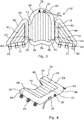
- the cradle 10 has a seat section 14, a back-support section 16 and opposed side panel sections 18, 20, each section being a soft-walled pneumatically-inflatable structure.
- the seat section In an upright condition when the cradle is inflated, as illustrated in Figures 1 to 4 , the seat section is located generally horizontally on a supporting surface and the back-support section 16 extends upwardly from a rear edge of the seat section 14.
- the side panel sections 18, 20 are located on opposite sides and extend forwardly between the back-support section 16 and seat section 14 to which they are connected.
- the back-support section 16 may be slightly reclined rather than vertical for patient comfort.
- the side panel sections 18, 20 are each connected with seat section 14 and the back-support section 16 and are operative to hold the back-support section 16 in position extending generally upwardly from the seat section 14 in a self-supporting manner when a patient is sitting in the cradle with their back resting on the back-support section.
- the term "self-supporting seat structure” is used to refer to a structure which is capable of independently supporting a patient in an upright sitting position when the seat section 14 is located on a supporting surface without any external support to hold the back-support section 16 extending upwardly.
- Relative directional terms such as “upper” and “lower”, “forward” and “rearward” and the like used in relation to the cradle or parts thereof refer to the cradle when in the upright inflated configuration as shown in Figure 1 and should be understood accordingly. However, it will be appreciated that the cradle can be used in other orientations.
- upright sitting position refers to a position in which the patient's buttock region is supported on the seat section 14 when the seat section is generally horizontal, with their torso generally upright so that their upper legs extend at an angle to their upper body. Typically the patient's upper legs will extend at an angle to their torso in the range of 80 to 140 degrees, or more particularly 85 to 120 degrees.
- the term "sitting position” as used herein in relation to a patient supported in the inflated cradle refers to a position in which is similar to that of an upright sitting position as defined above but covers the situation where the seat section is not horizontal. The term “sitting position” thus covers the situation where the patient is supported in the inflated cradle but with the back-support section horizontal on a supporting surface and the seat section extending upwardly from the support surface.
- supine position refers to a position which the patient is lying on their back with their legs extending out in front of them on a surface on which they are lying. In this position, the patient's legs will be generally flat so that their upper thighs are in-line with their back. It will be appreciated that in practice the patient's thighs may be angled slightly, though not to the same extent as when the patient is in a sitting position.
- each of the side panel sections 18, 20 When viewed in elevation from a side of the inflated cradle, each of the side panel sections 18, 20 is generally triangular in shape having a lower horizontal edge 22, a rear edge 24 which extends generally upwardly from the lower edge, and an angled forward edge 25 which extends from a forward end of the lower edge 22 to the upper end of the rear edge 24.
- the side panel sections 18, 20 are each connected along their rear edge 24 with a respective side edge region 26 of the back-support section 16 and along the lower edge 22 with the corresponding side edge region 28 of the seat section 14. Whilst a triangular shape has been found to be particularly advantageous for the side panel sections, it will be appreciated that the shape of the side panel sections can be varied.
- the cradle 10 in this embodiment is formed in two separable parts 32, 34 connected together by means of releasable fasteners 30.
- the parts can be separated and positioned about a patient when un-inflated and subsequently connected together before being inflated.
- Each part is independently inflatable, though in practice both parts are typically inflated at the same time.
- the side panel sections 18, 20 are constructed integrally with the back-support section 16 to form a first part 32 of the cradle and the seat section 14 is a separate component which forms a second part 34.
- the lower edge regions 22 of the side panel sections are releasably attached to the sides 28 of the seat section 14 by means of the releasable fasteners 30.
- Each part 32, 34 of the cradle is a separately inflatable soft-walled body having a one-way inlet valve 36 through which air under pressure can be introduced to inflate the body and a release or dump valve 38 which can be selectively opened to allow air to escape to deflate the body.
- Each of the two parts 32, 34 of the cradle are made from thin sheet material which is tough but very flexible and is impervious to air.
- the parts may be made of fabric material suitably treated to make it impervious to air, such as a polyurethane-coated nylon fabric for example.
- the material is formed into a bag-like structure or bladder for holding a volume of pressurised air (that is to say air at a pressure above the ambient air pressure).
- pressurised air that is to say air at a pressure above the ambient air pressure.
- each part 32, 34 When un-inflated, each part 32, 34 is relatively thin and highly flexible and so is easily positionable beneath and/or about the patient when they are laid or sitting on a bed, chair or other similar supporting structure, for example in a manner similar to that used to position a glide sheet.
- each part 32, 34 has a thickness substantially equal to twice the thickness of the sheet material from which it is made and has a flexible, fabric-like structure.
- Each part 32, 34 has opposed walls which define the major surfaces of the part when inflated.
- the opposed walls are interconnected by a series of internal webs and/or welds which limit their separation as the part is inflated in order to give a desired profile when inflated.
- the parts are profiled in this way so that each inflatable section 14, 16, 18, 20 defines a generally cylindrical outer frame portion 40 and a fluted region 41 within the outer frame to give the sections structural stability when inflated.
- the opposed walls in the first part 32 are welded together to define a hinge portion 42 between the back-support section 16 and each side panel section 18, 20.
- Fluid passages 43 are defined through the hinge portions 42 so that the back-support section 16 and the two side panel sections are fluidly interconnected to enable them to be inflated from a single inlet valve 36 and deflated through a single dump valve 38.
- each side panel section 18, 20 could alternatively be fluidly connected with the back-support section 16 by means of an external fluid connection having a coupling incorporating a non-return valve and in which parts of the coupling are connected to their respective section by a flexible hose.
- the seat section 14 is in the form of an inflatable cushion for positioning under the thighs and buttock region of the patient. It has a generally rectangular profile in plan when viewed from above but with a recessed region or indent 44 centrally located along the rear edge 46 between a pair of rearwardly projecting shoulders 48.
- the opposed walls which define the major surfaces of the seat section are an inner or upper wall 50 on which the patient sits and an outer or lower wall 52 for positioning on a support surface when the cradle is positioned upright.
- the cylindrical outer frame portion 40 extends along either side and across the front of the seat section.
- the fluted region 41 When inflated, the fluted region 41 has a depth in the region of 3 cm to 10 cm so that a person seated on it can be stably supported with their buttocks and upper thighs raised off a support surface on which the lower wall 52 of seat section 14 is positioned.
- the opposed walls which define the major surfaces are an inner wall 53 which is directed towards the patient in use and an outer wall 54 which is directed away from the patient.
- the back-support section 16 and each of the side panel sections 18, 20 define an internal volume for containing a quantity of pressurised air so that they each form a substantially rigid, panel-like structure when inflated.
- the side panel sections 18, 20 are pivotally connected to the back-support section 16 along the hinge portions 42 where the inner and outer walls are welded together so that when the second part is inflated, the rigid side panel sections 18, 20 can be moved relative to the rigid back-support section and can be positioned to extend forwardly, substantially perpendicular to the back-support section 16.
- the lower edge of the back-support section 16 has a central concave recess 56 between a pair of downwardly projecting shoulders 58 on either side.
- the central recess 56 aligns with the recessed region 44 along the rear edge of the seat section 14.
- the cradle 10 is configured so that the seat section 14 is received in the space defined between the back-support section 16 and the two side panel sections 18, 20, when all the sections are inflated and the side panel sections 18, 20 are positioned to extend forwardly from the back-support section 16.
- a plurality of releasable fasteners 30 is provided to connect the lower edge region 22 of each of the side panel sections 18, 20 to a respective side edge region 28 of the seat section.
- fasteners 30 are provided on each side and the fasteners are quick-release buckle type fasteners, each comprising a female buckle member 60 attached by means of a flexible strap 62 to an outer, lower edge region 22 of the respective side panel portion 18, 20 and a corresponding male buckle member 64 attached by a flexible strap or other fastening 66 to a respective side edge region 22 of the seat section 14.
- the buckle type fasteners 30 may be in the form of quick-release spring clips similar to those used on rucksacks in which the female buckle member 60 has a pair of resilient arms which are squeezed together for insertion into the male buckle member 64 and which after insertion spring out to engage with locking detents on the male buckle member 64 to prevent the female buckle member being pulled back out of the male member without first squeezing the resilient arms together. Apertures in the male buckle member 64 allow a user to squeeze the resilient arms inwardly to release the female buckle member. At least one of the straps 62, 66 may be adjustable in length to allow the angle of the back-support section 16 to be adjusted relative to the seat section 14 once the cradle has been inflated.
- the releasable fasteners 30 transit forces in tension between the seat section 14 and the respective side panel section 18, 20 to hold the back-support section 16 upright though the side panel sections 18, 20 when the cradle is inflated.
- the fasteners 30 must be capable of transmitting sufficient force that the back-support section 16 is held upright when a patient is sitting in the inflated cradle with their upper torso resting on the back-support section 16 without the aid of any external support for the back-support section.
- the cradle 10 This enables the cradle 10 to independently hold a patient in an upright sitting position when the cradle is positioned upright but where there is no external support against which the back-support section 16 of the cradle can be positioned, such as when the cradle is in the middle of a bed or when being moved between supporting surfaces, the forces that must be transmitted will depend on the size and weight of the patient but can be significant for use with bariatric patients.
- releasable fasteners 30 of any suitable type can be used to connect the seat section 14 and side panel sections 18, 20 subject to the requirements discussed above. These might include, for example, toggle fasteners, hook and loop fasteners, or strap and buckle type fasteners such as those described in relation to a third embodiment of the cradle described below.
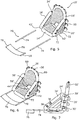
- FIGS 5 to 8 illustrate an alternative embodiment of a patient cradle 10' also in accordance with the first aspect of the invention.
- the cradle 10' is similar to the cradle 10 according to the first embodiment as described above to which the reader should refer and so only the significant differences will be described in detail.
- the main difference between the cradle 10' in accordance with the second embodiment and the first embodiment is that the side panel sections 18', 20' are integral with the seat section 14 to comprise the second part 34' of the cradle, with the back-support section 16 on its own forming the first part 32'.
- the parts 32', 34' are manufactured in a similar manner to those of the first embodiment from a flexible membrane or fabric-like material formed into a bag-like or bladder structure for holding a volume of pressurised air with the opposed walls interconnected by a series of internal webs and/or welds in order to give a desired profile when inflated.
- the opposed walls in the second part 34' are welded together to define a hinge portion 42' between the side edges 28' of the seat section 14' and the lower edge region 22' of each side panel section 18', 20'.
- the side panel sections 18', 20' are releasably connectable along their rear edge regions 24' to respective side edge regions 26' of the back-support section 16' by means of a plurality of releasable fasteners 30', similar to those used in the first embodiment to attach the side panel sections to the seat section as described above.
- Figure 8 illustrates how the straps 66' connecting buckle members to the sides of the back-support section 16' can be lengthened to allow the back-support section 16' to be reclined. Usually, the straps 66' are adjusted to hold the back-support section 16' in close contact with the rear edge regions 24' of the side panel sections when the cradle is being fitted and during inflation.
- Adjustment to allow the back-support section 16' to be reclined will usually only be carried out after the cradle is fully inflated where this is desirable for the comfort of the patient and is safe to do so. Similar adjustment of the fasteners 30 is possible with the first embodiment to allow the back-support section 16 to be reclined.
- the lower end of the back-support section 16' has a more pronounced central recessed region 56' and downwardly projecting shoulders 58', whilst the recess 44' along the rear edge of the seat section 14' is less pronounced.
- the shapes of the recess 44, 44', 56, 56' in the seat and back-support sections in any of the embodiments disclosed herein can be varied to suit particular applications. Accordingly, the cradle 10' in accordance with the second embodiment could have seat and back-support sections having recesses shaped like those of the first embodiment and vice versa. However, it should also be noted that the seat section and/or back-support section could be formed without a recess 44, 44', 56, 56'.
- a leg support attachment 70 can be used in conjunction with the cradle 10'.
- a number of flexible hoops 72 are spaced along the outside of the lower edge region 22' of each of the side panel sections 18' 20'.
- the hoops 72 are aligned and dimensioned to receive elongate side bars 74 which engage in the hoops along respective sides and project forwardly of the seat section.
- the side bars 74 are rigid and weight-bearing and may be round, tubular members made from any suitable but preferably light weight load-bearing material.
- Each side bar 74 could be made up of a number of sections which are releasably connected together.
- a sling or support 76 made of a flexible material has hoops 78 on either side which can be slid over the forward ends of the side bars 74.
- the sling 76 is arranged to locate under the lower legs/calf region of a person seated in the cradle so as to hold and support their legs projecting straight out in front. This may be necessary for patients who have had hip or knee joint replacements or where it is otherwise desirable that the patient's legs be supported.
- the leg support 70 also enables the cradle 10' to be used to automatically sit a patient upright from a supine position during inflation, as will be described later.
- the number of hoops 72 along each side of the cradle can be varied and some drawings show two hoops 72 whilst others show three.
- the hoops 72 could be provided on the sides of the seat section 14'.
- the side bars 74 may also project rearwardly beyond the cradle to provide additional stability.
- the cradle 10 in accordance with the first embodiment can be adapted to receive a leg support attachment 70 and it will be appreciated that other arrangements for attaching a lower leg support to the cradle could be adopted in any of the embodiments.
- Figures 5 to 8 also show how grab handles 80 can be provided on the cradle at various locations.
- the handles can be grasped by a care giver to assist in manoeuvring the inflated cradle 10' with a patient on-board.
- Similar grab handles 80 can be provided on the cradle according to any of the embodiments described herein.
- a range of cradles 10, 10' in different sizes can be provided. It is expected that for most applications the cradle 10, 10' will be dimensioned to support an adult, including bariatric adults, although versions for children or smaller adults may also be useful. For use with very large bariatric patients, the two parts of the cradle may have to be so large that they become difficult to handle and manipulate around the patient. To overcome this problem, one or both of the seat section 14, 14' and the back-support section 16, 16' could be split into two or more parts that can be fastened together, say using releasable fastenings similar to the fasteners 30.
- the seat section 14, 14' and the back-support section 16, 16' could each be made in two separately inflatable halves that are fastened together once placed in position about the patient.
- Each part would be provided with its own inlet valve 36 and outlet dump valve 38.
- the two parts may be fluidly interconnected by means of an external releasable fluid coupling so that they can be inflated through a single fluid inlet.
- the cradle may have separable side panel sections 18, 20, 18', 20' which are releasably connectable to both the back-support section 16, 16' and the seat section 14, 14'.
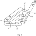
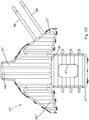
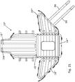
- a third embodiment of an inflatable cradle 10" in accordance with the invention and which has separable back-support 16", seat 14", and side panel sections 18", 20" is shown in Figures 9 and 10 .
- Each inflatable section 16", 14", 18", 20" is constructed in a similar manner to the corresponding section in the previous embodiments and is made from similar materials. The reader should refer to the description of the previous embodiments for details.
- each side panel section 18", 20" is a separate inflatable body which is releasably attachable to both the seat section 14" and the back-support section 16".
- Each side panel section 18", 20" is releasably connectable to the seat section 14" by means of a first set of releasable fasteners 30a and with the back-support section 16" by means of a second set of releasable fasteners 30b.
- the releasable fasteners 30a in the first set are each operative between the lower side edge region 22" of the side panel section and the respective side edge region 28" of the seat section 14", whilst the releasable fasteners 30b in the second set are each operative between the rear edge region 24" of the side panel section and the respective side edge region 26" of the back-support section 16".
- Each fastener 30a, 30b comprises a conventional type buckle 64" attached to an outer surface of the side panel section 18", 20" and a corresponding flexible strap 66" attached to the respective side edge 26", 28" of the back-support section 16" or seat section 14".
- the strap 66" is releasably and adjustably secured to the buckle 64" in the usual manner.
- the strap 66" has a number of holes spaced along its length into which a pin on the buckle can be inserted.
- Other types of buckle such as a cam buckle or a ladder buckle could be used. Indeed, other forms of releasable fastener could be used to attach the side panel sections such as the fasteners 30 described in relation to the previous embodiments.
- All the sections 14", 16", 18", 20" are inflated via a single one-way inlet valve 36 located on the rear surface at the top of the back-support section 16".
- the inlet valve 36 has a female coupling 36a fluidly connected with the interior of the back-support section by a flexible hose 36b.
- the female coupling 36a includes a non-return valve.
- the interior of each side panel section 18", 20" is fluidly connected to the interior of the back-support section 16" by means of a first external fluid connector 85a and with the interior of the seat section 14" by means of a second external fluid connector 85b.
- Each fluid connector includes a female coupling 86a having a non-return valve and a male coupling 86b which is releasably insertable into the female coupling 86a to create a flow path.
- the non-return valve prevents pressurised air flowing out of the respective body section through the female coupling 86a when the male coupling 86b is disconnected.
- Each female and male coupling 86a, 86b is fluidly connected to the interior of its respective section of the cradle by a flexible hose 87. It is preferred that in the second fluid connectors 85b, the female coupling is connected with the interior of the respective side panel section 16", 18". This enables the seat section 14" to be separated from the side panel sections 16", 28" when the cradle is inflated without the side-panel sections 16", 18" and the back-support section 16" deflating.
- a fluid path is created between all the sections of the cradle 10" so that the cradle can be inflated from a single source of pressurised air connected to the inlet valve 36.
- the source of pressurised air will typically have an outlet hose with a male coupling which is insertable in the female coupling 36a of the inlet valve to allow air under pressure to be introduced into the cradle from the source. Once inflated, the source of pressurised air can be disconnected by withdrawing the male coupling from the female coupling 36a, the non-return valve in the female coupling 36a retaining the pressurised air in the cradle.
- the second fluid connectors 85b can be disconnected to enable the seat section 14" to be deflated and/or removed from the remainder of the cradle whilst the side panel sections and the back-support section remain inflated.
- the seat section 14" can be subsequently re-inflated by reconnecting the second fluid connectors 85b and topping up the fluid pressure through the inlet valve 86.
- inlet valve 36 Whilst there is only one inlet valve 36 in the present embodiment, additional inlet valves could be provided. For example a further inlet valve could be provided on the seat section 14".
- Each of the seat, back-support, and side panel sections 14", 16", 18", 20" is provided with a dump valve 38 to enable the various sections to be deflated quickly and easily.
- External fluid connectors similar to the connectors 85a, 85b described above can be adopted in the inflatable cradle 10, 10' according to either of the first two embodiments to fluidly interconnect some or all of the inflatable sections in those cradles and to allow inflation of the cradle from a single inlet.
- a similar inlet valve arrangement to that used in the cradle 10" according to the third embodiment can be adopted for the inlet valves 36 in either of the cradles 10, 10' according to the first and second embodiment.
- the cradle 10" has a pair of safety restraints 88 which are releasably connectable between the forward edge regions 25" of the side panel sections 16", 18" to securely hold a patient in the cradle when it is inflated.
- Each restraint 88 comprises a flexible strap 88a attached to a forward edge region 25" of one of the side panel sections 20" and a corresponding buckle 88b attached to the forward edge region 25" of the other of the side panel sections 18".
- the straps 88a are releasably and adjustably secured across the front of the inflated cradle using the buckles 88b.
- the number and position of the restraints 88 can be varied.
- Similar restraints can be provided on the cradle 10, 10' according to either of the previous embodiments.
- Other arrangements for releasably securing a strap or similar restraint across the front of the cradle can be adopted.
- Other arrangements for holding a patient securely in the cradle can also be adopted, such as a harness or the like.
- the cradle 10" according to the third embodiment can be provided with a rigid leg support 70 similar to that described above in relation to the second embodiment 10'.
- hoops 72 of flexible material can be provided spaced apart along the side edge regions of the side panel sections 18", 20" or the seat section 14".
- other means of releasably securing a leg support 70 can also be adopted.
- At least the surfaces on the cradle 10, 10', 10" which the patient will come into contact with may be made from or covered with a material of relatively low frictional resistance. Such materials are sometimes referred to as high slip materials.
- the material could be provided in the form of separate sheets that are placed between the cradle 10, 10', 10" and the patient each time it is used or in the form of covers that are semi-permanently fitted over the various parts of the cradle.
- the covers may be removable to allow for replacement, repair and/or cleaning.
- a low friction material may be permanently applied to the relevant surfaces of the cradle.
- the low friction/high slip material may be polyester and/or nylon or any other suitable material such as are used in the manufacture of glide sheets for patient transfer.
- the low friction/high slip material may comprise a base material coated with silicon or some other low friction substance. It should be assumed in the following description of the use of the cradle that a high slip material is always in position between the cradle and the patient. If this material is not present on the cradle parts themselves, then sheets of high slip material are placed between the parts of the cradle and the patient during the following procedures.
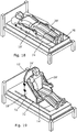
- FIGS 11 to 17 illustrate somewhat schematically a sequence for positioning a patient in the cradle 10' according to the second embodiment. Similar procedures modified accordingly can be adopted for the cradle 10, 10" in accordance with the first and third embodiments.
- the patient 82 is initially in a supine position on a bed 84 and may have insufficient upper body strength to support themselves in a sitting position on the bed.
- the two parts 32', 34' of the cradle 10' are separate and in a fully deflated condition.
- the patient 82 is first rolled over to one side as shown in Figure 11 .
- the back-support portion 16' is folded in half longitudinally and placed on the bed behind the patient's back and tucked in as close to the patient as possible.
- the second part 32', including the seat section 14' and the side panel sections 18', 20', is similarly folded in half and placed on the bed behind the patient's buttocks and thighs as close to them as possible.
- the patient 82 is gently rolled back into the supine position on top of the folded parts of the cradle and then onto their other side as shown in Figures 12 and 13 .
- the folded half of the back-support section 16' is teased through under the patient so that the back-support section is lying flat on the bed.
- the folded half of the seat section 14' and the attached side panel 20' on that side are teased through under the patient until they lie flat on the bed.
- the patient is now rolled back into the supine position so that they are lying with their back on the un-inflated back-support section 16' and at least their upper thighs on the seat section 14'.
- the back-support section 16' is pulled down the bed so that its lower end is as close to the patient's buttocks as possible and the seat section 14' is pulled up the bed so that its rear edge is as close to the patient's buttocks and to the lower end of the back-support section as possible.
- the material at the lower end of the back-support section 16' and the rear end of the seat section 14' may be bunched up around the patient's buttocks/hips so that when these sections inflate, the material works its way further under the patient to assist in lifting them off the surface of the bed.
- the side panel sections 18', 20' are manoeuvred up and around and the fasteners 30 engaged to attach each side panel section 18', 20' to its respective side of the back-support section 16'.
- the dimensions and the flexibility of the parts of the cradle allow the side panel sections 18', 20' to be attached to the back seat portion 16' when the cradle is un-inflated whilst the patient remains in a supine position with their legs generally flat on the bed as shown, somewhat schematically, in Figure 14 .
- the sides of the un-inflated back-support section are able to curve around the sides of the patient's torso whilst the sides of the un-inflated seat section are able to curve up around the sides of the patient's upper thigh/buttock region to enable the side panel sections to be attached whilst the patient's legs remain largely flat on the bed.
- the straps of the fasteners 30 at this stage are adjusted as short as possible so that the rear edges of the side panel sections 18', 20' are held close to the sides of the back-support section 16'.
- the cradle 10' is now ready to be inflated using a portable air compressor (not shown) or other source of pressurised air connected to the inlet valves 36 of both parts of the cradle so that they are inflated simultaneously. Compressed air is introduced into both parts 32', 34' but as a significant proportion of the weight of the patient is concentrated on the seat section 14' and the back-support section 16', the side panel sections 18', 20' will tend to inflate first. This has the effect of drawing the back-support section 16' forwardly (down the bed) so that the patient's buttocks are moved onto the seat section 14'.
- a portable air compressor not shown
- other source of pressurised air connected to the inlet valves 36 of both parts of the cradle so that they are inflated simultaneously. Compressed air is introduced into both parts 32', 34' but as a significant proportion of the weight of the patient is concentrated on the seat section 14' and the back-support section 16', the side panel sections 18', 20' will tend to inflat
- the seat section 14' and back-support sections are moved out of their common plane and become angled relative to one another to form a seat structure.
- the weight of the patient holds the back-support member 16' on the bed and the lower surface of the seat section is drawn off the bed such that the patient's upper legs are raised off the bed to place them in a "sitting position" but with the back-support section 16' lying flat on the bed. This is illustrated in Figure 15 .
- the seat section 14' is drawn fully onto the patient's buttocks and held tight against the lower edge of the back-support section either side of the recess 56'.
- the patient is now supported in the cradle and the patient and cradle 10' can be gently tilted forwardly to place them in an upright sitting position with the seat section 14' on the upper surface of the bed mattress as shown in Figures 16 and 17 .
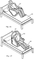
- FIGs 18 and 19 illustrate an alternative method using the lower leg support 70 in which the cradle is automatically raised to an upright sitting position as it inflates.
- the lower leg support 70 is attached to the cradle 10' after it has been placed about the patient and the two parts 32', 34' connected together but just prior to inflation.
- the side bars 74 are inserted into the hoops 72 on their respective sides and the sling 76 is attached to the forward ends of the side bars so that the sling is positioned beneath the patient's feet/lower calf region as illustrated in Figure 18 .
- the patient remains in a supine position.
- the cradle is now inflated.
- the weight of the patient's legs acting on the sling 76 of the leg support holds the seat section 14' flat on the bed so that the back-support section 16' and the side panel sections 18', 20, are drawn up off the bed to an upright position as shown in Figure 19 .
- the carers can assist in tilting the cradle forward as it inflates. This pneumatically raises the patient into an upright sitting position automatically and ensures that the patient's legs remain largely horizontal to the support surface of the bed at all times. If necessary, additional weight could be added to the leg support 70. This might be required where the patient is a single or double amputee, for example, but may also be required in other circumstances.
- the seat section 14 could be held in contact with the bed by means other than a lower-leg support. For example, other arrangements to weigh down the seat section or of applying a force to it to hold it in contact with the bed can be adopted.
- the cradle 10' is fully inflated and in an upright position on the bed or other supporting surface, the patient is stably supported by the cradle in a suitable upright sitting position for transfer. It will be recognised that the above-described sequences can be reversed to position a patient in bed from an inflated cradle.
- the cradle 10" according to the third embodiment is placed about a patient and inflated in a similar manner but the main differences will now be described.
- the seat, back-support, and side panel sections 14", 16", 18", 20" are all separate from one another and in an un-inflated condition.
- the seat section 14" With the patient lying in a supine position on a bed or other support, the seat section 14" is positioned under their thigh/buttock region and the back-support section 16" is positioned under their back making sure that the rear edge of seat section 14" and lower edge of the back-support section 16" are as close together as possible or overlapping.
- the patient can be manoeuvred and rolled in the usual way during this part of the procedure.
- the side panel sections 18", 20" are then attached between the seat section 14" and the back-support section 16", using the releasable fasteners 30a, 30b, and the fluid connectors 85a, 85b are assembled.
- the side panel sections may be attached sequentially or at the same time depending on how many carers are present.
- the cradle is inflated by connecting a source of pressurised air to the inlet valve 36.
- the cradle 10" is inflated gradually so that the patient is moved into a sitting position safely and comfortably as the inflatable sections of the cradle inflate. If the cradle is used without a lower leg support 70, the patient will be placed in a sitting position but lying on their back and the cradle is then gently tipped forward to place the cradle and the patient in an upright sitting position with the seat section 14" on the bed, as described above in relation to Figures 14 to 17 .
- the cradle 10" If the cradle 10" is used with a leg support 70, then it will automatically tip forward gently as it is inflated, as described previously with regard to Figures 18 and 19 . When the cradle is fully inflated the source of pressurised air is disconnected from the cradle and the restraints 88 secured in position. The patient is now ready to be manoeuvred with the cradle.
- the above-described methods of positioning the un-inflated cradle about a patient are particularly suitable for patients with limited upper body strength who cannot sit upright on a bed unaided.
- the method can be adapted so that the un-inflated cradle, or at least part of it, is fitted with the patient in an upright sitting position on the bed.
- the seat section could be positioned beneath the patient whilst they are lying on the bed and the patient then sat up whilst the back-support section is located about their back and the side panel sections connected.
- the inflatable patient cradle 10, 10', 10" is a highly flexible piece of apparatus that can be used in many different ways to support a patient for transfer and for treatment or care.
- the above-described methods are only examples of a number of different methods that can be used to place a patient in the cradle.
- the cradle will be positioned about the patient un-inflated, the side panel sections connected between the seat section and the back-support section as required, and the cradle subsequently inflated to define the seat structure in which the patient is supported and raised off the surface on which they are located.
- the un-inflated cradle can be positioned about the patient, depending on the circumstances.
- the above methods describe the sections of the cradle being separated before the un-inflated cradle is positioned about the patient, it is not always necessary for any or all the parts to be separated.
- an un-inflated cradle 10, 10', 10" about a patient lying on a bed with good access from both sides, it may be possible to position the patient on the un-inflated cradle without separating any of the parts or by only disconnecting one of the side panel sections from at least one of the seat section and the back-support section.
- the ability to separate the various parts of the cradle does provide for flexibility in the way the cradle can be fitted and removed.
- the seat section 14 is separated from the back-support section so that these can be positioned about the patient or removed independently of one another. Furthermore, the ability to remove the side panel sections, or at least move them out of the way about hinges, makes it possible for a patient to be moved sideways on or off the seat section and back-support sections.
- forming the cradle with at least two separable parts also allows parts of the cradle to be removed for cleaning or repair and for a part of one cradle to be used with a part from another similar cradle. It also enables a cradle to be provided with different, interchangeable seat sections adapted for different applications.
- a seat section 14, 14', 14" could be provided with a toileting aperture and a user could choose whether to use a standard seat section with no toileting aperture or a seat section with a toileting aperture in the cradle.
- FIGS 20 and 21 illustrate two further embodiments of an inflatable cradle 10"', 10"". These embodiments are similar to the embodiments 10 and 10" shown in Figures 1 to 4 and Figures 5 to 8 respectively, except that they are formed as a single integral member in which the seat section 14"', 14"" and the back-support section 16"', 16"" are interconnected by a flexible hinge portion 45, similar to hinge portions 42, 42' as described above. There is no recess along the rear edge of the seat section or the lower edge of the back-support section but the seat section is provided with a toileting aperture 47.
- a cradle 10"', 10"" in accordance with these embodiments can be positioned about a patient lying or sitting on a surface, such as a bed, using methods similar to those described above.
- at least one side panel section 18"', 20'"; 18"", 20"” may be disconnected from the seat section or back-support section as appropriate.
- the side panel sections are re-attached as required and the cradle inflated.
- the cradle With a patient supported in the inflated cradle in an upright sitting position, the cradle can be moved to place the patient over a toilet or commode and the patient toileted. After toileting, the procedure can be reversed to return the patient to bed.
- a toileting aperture 47 similar to that shown in Figures 20 and 21 can be adopted in the seat sections 14, 14', 14"of any of the embodiments of the cradle 10, 10', 10" previously described. Where a toileting aperture 47 is adopted, the seat section may not have a recess along its rear edge to ensure there is sufficient area to lift and support the patient. For use with a seat section having a toileting aperture 47, a replaceable protective membrane or cover may be placed between the patient and the seat section and which extends into the toileting aperture to reduce soiling of the seat section.
- the back-support section In order to stably hold a patient in an upright sitting position, the back-support section must extend to a suitable height, which will typically be at least up to shoulder height for the intended user but may also extend to head height and the back-support section could incorporate a head rest portion 16a as illustrated in Figures 20 and 21 .
- the side panel sections must extend sufficiently far up the back-support section that they hold the back-support section upright over its full height. Typically, the patient's arms are constrained within the side panel sections when the cradle is inflated. In addition to acting in tension to hold the back-support section upright, the side panel sections contact both the seat section and the back-support section to act in compression to prevent the back-support section being tipped forwardly beyond the vertical. This is helpful when a patient is being transferred in the cradle so that they are not inadvertently tipped forward out of the cradle.
- the cradle In order to stably support a patient in an upright sitting position and in order to be able to lift the patient dynamically as the cradle inflates, the cradle must be inflated to a suitably high pressure to provide the required lift and rigidity.
- the pressure required to lift a patient depends on their weight and the area of the inflatable section which is doing the lifting, which will either be the seat section or the back-support section.
- the cradle In use to lift a patient having a weight in the region of 95 kg to 127 kg, which is a typical weight range for adults in a care home or hospital, it has been found in one embodiment that the cradle would typically be inflated to a pressure of around 27 kPa to 34 kPa.
- a lower pressure could potentially be used if the surface area of the inflatable sections is increased, provided the inflatable cradle is sufficiently rigid to support the patient once inflated.
- the inflatable sections of the cradle should be constructed to be able to withstand the maximum pressure required for its intended use.
- the cradle With a patient 82 supported in an upright sitting position in the inflated cradle 10, 10', 10", 10"', 10"", the cradle can be manoeuvred across a surface manually, perhaps with the assistance of a glide sheet or other low friction material placed between the seat section 14' and the surface.
- the cradle 10, 10', 10", 10"', 10”” could also be provided with attachments to enable it to be lifted by means of a crane or hoist, with the patient safely on-board.
- a detachable strap could be provided to enable a carer to pull the cradle along.
- the cradle can be used in conjunction with a variety of apparatus which comprise rollers over which the cradle can be moved manually with relative ease and safety to form a highly flexible and easy-to-use modular system for moving patients.
- a mobile transfer unit 110 can be used in conjunction with a roller transfer assembly 90 to move a person onto or off from a bed, or other surface, whilst supported in an inflated cradle 10' in accordance with an aspect of the invention.
- the mobile transfer unit 110 With the patient supported in an upright sitting position in the inflated cradle 10' and the cradle positioned on top of the roller transfer assembly 90 extending transversely across the bed, the mobile transfer unit 110 is positioned with one side adjacent a side of the bed and with a platform 118 in line with the roller transfer assembly 90 and the cradle 10'.
- Brakes on the mobile transfer unit are applied and the height of the platform 118 is adjusted to bring the top of a set of rollers 96 on the mobile unit 110 broadly into the same plane as the top of the rollers 96 in the roller transfer assembly 90.
- a side restraint on the mobile transfer device adjacent the bed is removed, or raised so as to be out of the way, to allow access to the platform 118, and a leg support panel 130 raised.
- a safety buffer 105 may be attached to the roller transfer assembly 90 at the end distal from the mobile transfer unit 110 to ensure the cradle does not unintentionally roll off the assembly at that end.
- a further safety buffer could be attached to the roller transfer assembly at the end proximal to the mobile transfer unit when the cradle 10' is positioned on the assembly 90 and only removed when the mobile transfer unit 110 is in position and it is safe to move the cradle from the roller transfer assembly and on to the mobile transfer unit.
- the cradle 10' With the mobile transfer unit 110 in position and adjusted as required, the cradle 10' is moved laterally along the roller transfer assembly 90 towards and onto the rollers 96 in the platform 118. Once the cradle 10' is in position and fully supported on the platform 118, the side restraint adjacent the bed is replaced to ensure the cradle 10' cannot slide off the platform to the side.
- the leg support panel 130 can be lowered if desired and the height of the platform 118 adjusted as required so that the patient can be moved to another location on the mobile transfer unit whilst stably supported in the inflated cradle.
- the patient could be moved to a new bed or subsequently returned to the same bed where the above-described sequences are reversed in order to place the patient in the middle of the bed.
- Similar procedures can be used to move a patient between the mobile transfer unit 110 and any suitable, generally horizontal support surface having a height within the range of adjustment of the platform 118.
Description
- The present invention relates to patient handling. The invention relates in particular to apparatus and methods for moving a patient and especially, but not exclusively, to apparatus and methods for transferring a disabled, elderly and/or infirm person.
- People who are severely ill, elderly, disabled or otherwise infirm may lose the ability to move freely on their own and require assistance for repositioning and movement. This is a particular issue for people who have insufficient upper body strength to support themselves in an upright sitting position without assistance and for people who are very heavy, such as bariatric patients. The responsibility for assisting such people falls to care providers who reposition patients to prevent pressure ulcers and promote comfort and who transfer patients between supporting structures, such as between beds, chairs, wheelchairs or patient trolleys for example. In some situations, a person must be transferred vertically, say between equipment with support surfaces of different heights. In other cases, the transfer is predominantly in a lateral or otherwise generally horizontal direction. This might be the case where a patient is repositioned on a bed or is transferred between adjacent surfaces at the same height, such as between a bed and an adjacent patient trolley, or between a chair and a commode, for example.
- Research has shown that care providers experience significant physical stress when performing manual lifting and repositioning tasks which can lead to physical injury, including musculoskeletal disorders that can cause chronic back pain. Manual handling is also undesirable for the patient who is at risk of pain and discomfort, skin tears, bruising and being dropped, as well as suffering indignity. One of the highest risk manual handling activities is transferring a patient on or off a bed. This often requires the care provider to reach across the bed adopting a bad posture which can result in high physical stress to their body, particularly their back. The relatively soft nature of bed mattresses adds to the difficulty as they tend to compress when a force is applied, making it more difficult to move a patient safely and efficiently.
- To alleviate the problems outlined above, various apparatus and methods have been developed over the years. Technologies to assist with vertical transfer of patients include powered full-body sling lifts, floor-based lifts, ceiling-mounted lifts, powered standing lifts, non-powered standing aids and gait/transfer belts. Technologies to assist with horizontal/lateral transfer and repositioning of patients include air-assisted systems, friction-reducing devices such as glide sheets, mechanical lateral transfer aids, sliding boards and transfer chairs.
-
US 2007/028380 A1 discloses a lift device including a plurality of inflatable bladders. - The apparatus developed so far have significant drawbacks. Glide sheets are easily positionable beneath a patient lying on a surface using the so-called "log roll" technique in which the patient is first rolled over to one side and then to the other to enable the sheet to be manoeuvred into position. However, they offer little support to the patient who may feel vulnerable during transfer. For patients who are unable to sit-up unaided, glide sheets are generally used with the patient lying supine and so are of limited use in transferring such a patient where they must be moved between lying and sitting positions. Whilst glide sheets reduce friction between the patient and the surface on which they are lying or sitting, they still often require significant force to be applied to manually move the patient. Transfer boards are useful for transferring a patient in a sitting position but are of limited use for patients who have insufficient upper body strength to support themselves unaided in an upright sitting position.
- Other types of apparatus require the patient to be manually lifted when positioning them on the equipment. This can be especially problematic when the patient is on a bed due to the soft nature of the bed mattress and the difficulty in reaching a patient positioned centrally within a bed.
- Powered lifting aids such as lifts and hoists are often expensive, heavy and bulky. Ceiling-mounted lifts operate on a fixed run and so do not offer flexibility of use. Mobile hoists tend to be large and difficult to manoeuvre and so are not always able to be used where access is limited. Storage of mobile hoists can also be problematic. Hoists and lifts are used with slings which must be carefully selected to suit the particular patient and also regularly cleaned and disinfected and, on occasion, disposed of altogether. A further issue with powered lifting aids is that they require significant training to use safely and competently.
- There is therefore a need for an improved apparatus for handling a patient which overcomes, or at least mitigates, the drawbacks of the known apparatus.
- There is also a need for an improved method of handling a patient which overcomes, or at least mitigates, the drawbacks of the known methods.
- In accordance with a first aspect of the invention, there is provided a method of handling a patient using apparatus including an inflatable patient transfer cradle, the cradle when inflated defining a self-supporting seat structure capable of holding a patient seated in the inflated cradle in an upright sitting position for transfer between different locations; the cradle having an inflatable seat section, an inflatable back-support section, and a pair of opposed inflatable side panel sections, each inflatable section comprising a soft-walled inflatable body which is flexible when un-inflated; the method comprising:
- a. positioning the un-inflated cradle about a patient with the seat section located beneath the patient's upper thigh/buttock region and the back-support section about the patient's back;
- b. subsequently inflating the cradle to define said seat structure about the patient;
- In the method of the first aspect, the un-inflated cradle may be positioned about a patient sitting upright on a supporting surface, the seat section being located between the patient's upper thigh/buttock region and the supporting surface, the patient's upper thigh/buttock region being lifted above the surface as the seat section is subsequently inflated.
- In an alternative embodiment, the un-inflated cradle is positioned about a patient lying on a supporting surface, the method comprising:
- a. positioning the un-inflated seat section and back-support section between the patient and the supporting surface on which they are lying and placing the patient in a supine position with the back-support section located beneath the patient's back and the seat section located beneath the patient's upper thighs;
- b. subsequently inflating the cradle such that the patient is drawn into a sitting position as the cradle inflates to define said seat structure.
- The seat section, the back-support section and the side panel sections may each have an inner surface which is directed toward a patient when sitting in the inflated cradle in use and an opposing outer surface which is directed away from the patient, in which case the step of positioning the un-inflated seat section and back-support section between the patient and the supporting surface on which they are lying may comprise positioning the seat section and the back-support section extending generally in a common plane on the supporting surface with their outer surfaces directed toward the supporting surface, the inner surface of the seat structure beneath and facing the patient's upper thigh/buttock region, and the inner surface of the back-support section beneath and facing the patient's back; the seat section and the back-support section being drawn into a configuration in which they extend at an angle to one another when the cradle is subsequently inflated to define said seat structure, with the inner surface of the back-support section being directed toward and supporting the patient's back. The seat section and the back-support section may be drawn into a configuration in which their inner surfaces extend at an angle in the range of 85 to 130 degrees, or more particularly at an angle in the range of 89 to 110 degrees, relative to one another to define said seat structure.
- In an embodiment, the method comprises inflating the cradle such that the outer surface of the back-support section remains in contact with the supporting surface and the seat section is drawn into a position in which its inner and outer surfaces extend generally upwardly from the supporting surface as the cradle is inflated to define said seat structure, the method further comprising tipping the inflated cradle with the patient on-board forwardly on to the outer surface of the seat section so as to raise the back-support section off the supporting surface and place the patient in an upright sitting position supported in the inflated cradle.
- Alternatively, the method may comprise holding the outer surface of the seat section in contact with the supporting surface as the cradle is inflated such that the outer surface of the back-support section is drawn off the supporting surface to automatically raise the patient into an upright sitting position as the cradle inflates to define the seat structure. The apparatus may further comprise a lower leg support releasably attachable to the cradle so as to extend forwardly from the seat section and the method may comprise attaching the lower leg support to the cradle and supporting the patient's leg(s) on the lower leg support before the cradle is inflated such that the weight applied to the lower leg support holds the outer surface of the seat section in contact with the supporting surface as the cradle is inflated.
- In an embodiment, each side panel section is releasably attachable to at least one of the seat section and the back-support section, and the step of positioning the un-inflated cradle about the patient is carried out with the cradle in an un-assembled configuration in which at least one side panel section is disconnected from at least one of the seat section and the back-support section; the un-inflated cradle subsequently being placed in an assembled configuration in which each side panel is connected to both the seat section and the back-support section prior to the step of inflating the cradle. Both side panel sections may be disconnected from at least one of the seat section and the back-support section when the cradle is in its un-assembled configuration for positioning about the patient.
- Each side panel section may be releasably attachable to both the seat section and the back-support section and at least one side panel may be disconnected from both the seat section and the back-support section when the cradle is in its un-assembled configuration for positioning about the patient. If desired, both side panel sections may be disconnected from the seat section and the back-support section when the cradle is in its un-assembled configuration for positioning about the patient.
- In an embodiment, the seat section is hingedly connected to the back-support section. In an alternative embodiment, the seat section is not directly attached to the back-support section and is connected to the back-support section only via the side panel sections. In a still further embodiment, the seat section is releasably attachable directly to the back-support section.
- In an embodiment, the cradle has at least two separable parts releasably attachable to one another, the at least two separable parts including a first part comprising at least the back-support section and a second part comprising at least the seat section, each side panel section extending between and connected to the back-support section and a respective side of the seat section when the at least two parts are assembled; and the step of positioning the un-inflated cradle about a patient comprises positioning the un-inflated cradle about the patient with the at least two parts separated and subsequently connecting the at least two parts together prior to the step of inflating the cradle.
- In an embodiment, the step of positioning the un-inflated cradle about a patient may comprise positioning the seat section and the back-support section between a patient and a surface on which they are lying and placing the patient in a supine position such that the back-support section is located beneath and its inner surface directed towards the patient's back and the seat section is located beneath the patient's upper thighs and connecting the at least two parts of the cradle together whilst the patient remains in a supine position prior to the step of inflating the cradle.
- The seat section may be profiled to define a central recess along a rear edge, and the step of positioning the seat section and the back-support section about a patient may comprise positioning the rear edge of the seat section about the patient's buttock region so that at least part of the patient's buttock/hip region is located in the recess for contact with the supporting surface prior to inflation of the cradle.
- The back-support section may be profiled to define a central recess along a bottom edge, and the step of positioning the back-support section and the seat section about a patient may comprise positioning the bottom edge of the back-support section about the patient's buttock region so that at least part of the patient's buttock/hip region is located in the recess for contact with the supporting surface prior to inflation of the cradle.
- In an embodiment, the cradle is inflated to a pressure of at least 27 kPa or at least 34 kPa.
- With a patient supported in the inflated cradle and the cradle in an upright position, the method may comprise manoeuvring the inflated cradle with a patient on-board across a surface.
- The method may comprise:
- a. supporting a patient in the inflated cradle in an upright sitting position on a first supporting structure;
- b. moving the cradle from the first supporting structure onto a second supporting structure whilst the patient is supported in an upright sitting position within the inflatable cradle during said movement.
- In accordance with a second aspect of the invention, there is provided apparatus for use in the method according to the first aspect, the apparatus comprising an inflatable patient transfer cradle which when inflated defines a self-supporting seat structure capable of holding a patient seated in the inflated cradle in an upright sitting position for transfer between different locations; the cradle comprising an inflatable seat section, an inflatable back-support section, and a pair of opposed inflatable side panel sections, each inflatable section comprising a soft-walled inflatable body which is flexible when un-inflated;
characterized in that the cradle is configured such that when inflated to define said seat structure and placed in an upright position on the seat section, the back-support section extends upwardly from the seat section with the side panel sections extending between and connected to the back-support section and the seat section on respective sides to define with the back-support section a volume within which the upper body of a patient sitting on the seat section is supported and held generally upright by the back-support section and the side panel sections, the side panel sections being operative in use to hold the back-support section extending upwardly from the seat section to support the weight of a patient's upper body in a self-supporting manner. - Each side panel section may be releasably attachable to at least one of the seat section and the back-support section. Each side panel section may be releasably attachable to both the seat section and the back-support section. The cradle may have a plurality of releasable fasteners for releasably attaching each side panel section to said at least one of the seat section and the back-support section.
- The seat section may be permanently and hingedly connected to the back-support section. Alternatively, the seat and back-support sections may not be directly connected and only attached to one another through the side panel sections when the cradle is assembled.
- In an embodiment, the cradle has at least two separable parts releasably attachable to one another, a first part comprising at least the back-support section and a second part comprising at least the seat section, each side panel section extending between and connected to the back-support section and a respective side edge of the seat section when the at least two parts are assembled.
- The side panel sections may be permanently attached to one of the seat section and the back-support section and releasably connectable to the other of the seat section and the back-support section to attach the first and second parts together, the cradle comprising a plurality of releasable fasteners for releasably connecting each side panel section to said other of the seat section and the back-support section. The side panel sections may be permanently attached to opposed sides of the seat section and releasably attachable to the back-support section or the side panel sections may be permanently attached to opposed sides of the back-support section and releasably attachable to the seat section.
- Each of the side panel sections may be releasably attachable to the seat section and to the back-support section, the cradle having on either side a first plurality of releasable fasteners for connecting a respective side panel section to the seat section and a second plurality of fasteners for connecting the respective side panel section to the back-support section.
- The cradle may be configured to be inflated to a pressure of at least 27 kPa or at least 34 kPa.
- The seat section may be profiled to define a central recess along a rear edge of the seat section.
- The back-support section may be profiled to define a central recess along a bottom edge.
- The seat section may define a toileting aperture.
- The interior of at least one of the seat section, the back-support section, and each of the side panel sections may be fluidly connected to the interior of at least one other of the seat section, the back-support section, and each of the side panel sections by an external fluid connection having a releasable coupling.
- The interiors of the seat section, the back-support section, and each of the side panel sections may be fluidly interconnected by external fluid connections, each fluid connection comprising a fluid coupling having inter-engageable male and female coupling parts.
- The cradle may have at least one safety restraint to retain a patient in the inflated cradle. The restraint may be releasably attachable across the front of the cradle between the side panel sections. The at least one safety restraint may comprise a strap secured to one of the side panel sections and having a free end releasably attachable to the other side panel section by means of a buckle or other fastening.
- For the avoidance of doubt, it should be understood that the term "patient" is used herein in a general context to refer to any person who requires assistance in moving and it should be recognised that the patient handling system and methods as described and claimed are not limited to use in a hospital or other formal medical or care facility and could be equally used in a person's private home or indeed any other setting.
- Several embodiments of the invention will now be described, by way of example only, with reference to the accompanying drawings, in which:
-
Figure 1 is a perspective view showing a first embodiment of an inflatable patient cradle which can be used as part of apparatus for handling a patient in accordance with the present invention, showing the cradle inflated; -
Figure 2 is a view from the side of the cradle ofFigure 1 ; -
Figure 3 is a view from the rear of a back-support section and integral side panel sections forming a first part of the cradle ofFigure 1 ; -
Figure 4 is a perspective view of a seat section forming a second part of the cradle ofFigure 1 ; -
Figure 5 is a perspective view of a second embodiment of an inflatable patient cradle which can be used as part of apparatus for handling a patient in accordance with the present invention but also showing elements of an associated lower leg support shown in exploded view; -
Figure 6 is a view similar to that ofFigure 5 but showing the lower leg support mounted to the cradle; -
Figure 7 is a view from the side of the cradle ofFigure 6 ; -
Figure 8 is a view from the side of the cradle ofFigure 6 but with the lower leg support omitted and showing a back-support section in a semi-reclined position; -
Figure 9 is a perspective view of a third embodiment of an inflatable patient cradle which can be used as part of apparatus for handling a patient in accordance with the present invention, showing the cradle in an assembled and inflated configuration; -
Figure 10 is an exploded view of the cradle ofFigure 9 ; -
Figures 11 to 17 are a series of perspective views illustrating fitting of the cradle ofFigures 5 to 8 about a patient lying on a bed, subsequent inflation of the cradle and positioning the patient in an upright sitting position supported in the inflated cradle; -
Figures 18 and 19 illustrate an alternative method of inflating the cradle ofFigures 5 to 8 using a lower leg support to automatically place the patient in an upright sitting position as the cradle inflates; -
Figures 20 and21 are views from above of two further embodiments of an inflatable patient cradle in accordance with the invention, showing the cradles in an un-assembled configuration for positioning about a patient; and -
Figures 22 and 23 are a series of perspective views showing a patient supported in the cradle ofFigures 5 to 8 being transferred from a bed onto a mobile transfer unit using a roller transfer assembly. -
Figures 1 to 4 illustrate a first embodiment of an inflatablepatient transfer cradle 10 in accordance with an aspect of the invention. The inflatable patient transfer cradle can be used as part of apparatus in a method of handling a patient in accordance with a further aspect of the invention but can also be used independently of the method. - The
cradle 10 is a pneumatically-inflatable device configured to be positioned in an un-inflated condition about a patient located on a surface and inflated to raise them off the surface. Once fully inflated, thecradle 10 forms a generally rigid, self-supporting seat structure in which the patient is stably and comfortably held in an upright sitting position for transfer in the cradle between different locations. Thecradle 10 can be used, for example, to reposition a patient on a support surface but can also be used to transfer a patient from one supporting structure to another, such as between a bed and a chair. - The
cradle 10 has aseat section 14, a back-support section 16 and opposedside panel sections Figures 1 to 4 , the seat section is located generally horizontally on a supporting surface and the back-support section 16 extends upwardly from a rear edge of theseat section 14. Theside panel sections support section 16 andseat section 14 to which they are connected. The back-support section 16 may be slightly reclined rather than vertical for patient comfort. - In the assembled and inflated cradle, the
side panel sections seat section 14 and the back-support section 16 and are operative to hold the back-support section 16 in position extending generally upwardly from theseat section 14 in a self-supporting manner when a patient is sitting in the cradle with their back resting on the back-support section. Accordingly, the term "self-supporting seat structure" is used to refer to a structure which is capable of independently supporting a patient in an upright sitting position when theseat section 14 is located on a supporting surface without any external support to hold the back-support section 16 extending upwardly. - Relative directional terms such as "upper" and "lower", "forward" and "rearward" and the like used in relation to the cradle or parts thereof refer to the cradle when in the upright inflated configuration as shown in
Figure 1 and should be understood accordingly. However, it will be appreciated that the cradle can be used in other orientations. - The term "upright sitting position" as used herein in relation to a patient supported in the inflated cradle refers to a position in which the patient's buttock region is supported on the
seat section 14 when the seat section is generally horizontal, with their torso generally upright so that their upper legs extend at an angle to their upper body. Typically the patient's upper legs will extend at an angle to their torso in the range of 80 to 140 degrees, or more particularly 85 to 120 degrees. The term "sitting position" as used herein in relation to a patient supported in the inflated cradle refers to a position in which is similar to that of an upright sitting position as defined above but covers the situation where the seat section is not horizontal. The term "sitting position" thus covers the situation where the patient is supported in the inflated cradle but with the back-support section horizontal on a supporting surface and the seat section extending upwardly from the support surface. - The term "supine position" as used herein in relation to a patient refers to a position which the patient is lying on their back with their legs extending out in front of them on a surface on which they are lying. In this position, the patient's legs will be generally flat so that their upper thighs are in-line with their back. It will be appreciated that in practice the patient's thighs may be angled slightly, though not to the same extent as when the patient is in a sitting position.
- When viewed in elevation from a side of the inflated cradle, each of the
side panel sections horizontal edge 22, arear edge 24 which extends generally upwardly from the lower edge, and anangled forward edge 25 which extends from a forward end of thelower edge 22 to the upper end of therear edge 24. Theside panel sections rear edge 24 with a respectiveside edge region 26 of the back-support section 16 and along thelower edge 22 with the correspondingside edge region 28 of theseat section 14. Whilst a triangular shape has been found to be particularly advantageous for the side panel sections, it will be appreciated that the shape of the side panel sections can be varied. - The
cradle 10 in this embodiment is formed in twoseparable parts releasable fasteners 30. The parts can be separated and positioned about a patient when un-inflated and subsequently connected together before being inflated. Each part is independently inflatable, though in practice both parts are typically inflated at the same time. In this embodiment, theside panel sections support section 16 to form afirst part 32 of the cradle and theseat section 14 is a separate component which forms asecond part 34. In this arrangement, thelower edge regions 22 of the side panel sections are releasably attached to thesides 28 of theseat section 14 by means of thereleasable fasteners 30. Eachpart way inlet valve 36 through which air under pressure can be introduced to inflate the body and a release or dumpvalve 38 which can be selectively opened to allow air to escape to deflate the body. - Each of the two
parts part part part inflatable section outer frame portion 40 and afluted region 41 within the outer frame to give the sections structural stability when inflated. In addition, the opposed walls in thefirst part 32 are welded together to define ahinge portion 42 between the back-support section 16 and eachside panel section Fluid passages 43 are defined through thehinge portions 42 so that the back-support section 16 and the two side panel sections are fluidly interconnected to enable them to be inflated from asingle inlet valve 36 and deflated through asingle dump valve 38. However, eachside panel section support section 16 by means of an external fluid connection having a coupling incorporating a non-return valve and in which parts of the coupling are connected to their respective section by a flexible hose. - The
seat section 14 is in the form of an inflatable cushion for positioning under the thighs and buttock region of the patient. It has a generally rectangular profile in plan when viewed from above but with a recessed region orindent 44 centrally located along therear edge 46 between a pair of rearwardly projectingshoulders 48. The opposed walls which define the major surfaces of the seat section are an inner orupper wall 50 on which the patient sits and an outer orlower wall 52 for positioning on a support surface when the cradle is positioned upright. The cylindricalouter frame portion 40 extends along either side and across the front of the seat section. When inflated, thefluted region 41 has a depth in the region of 3 cm to 10 cm so that a person seated on it can be stably supported with their buttocks and upper thighs raised off a support surface on which thelower wall 52 ofseat section 14 is positioned. - In the
first part 32 of the cradle, the opposed walls which define the major surfaces are aninner wall 53 which is directed towards the patient in use and anouter wall 54 which is directed away from the patient. The back-support section 16 and each of theside panel sections side panel sections support section 16 along thehinge portions 42 where the inner and outer walls are welded together so that when the second part is inflated, the rigidside panel sections support section 16. - The lower edge of the back-
support section 16 has a centralconcave recess 56 between a pair of downwardly projectingshoulders 58 on either side. Thecentral recess 56 aligns with the recessedregion 44 along the rear edge of theseat section 14. These two recessedregions seat section 14 and the back-support section 16 to be positioned about a person in an un-inflated condition whilst the person remains seated or lying on a surface without having to lift them fully off the surface, as will be described in detail later. This is particularly advantageous when positioning thecradle 10 about a person sitting upright on a chair where access to the patient from the side may be limited. - The
cradle 10 is configured so that theseat section 14 is received in the space defined between the back-support section 16 and the twoside panel sections side panel sections support section 16. A plurality ofreleasable fasteners 30 is provided to connect thelower edge region 22 of each of theside panel sections side edge region 28 of the seat section. In the present embodiment, threefasteners 30 are provided on each side and the fasteners are quick-release buckle type fasteners, each comprising afemale buckle member 60 attached by means of aflexible strap 62 to an outer,lower edge region 22 of the respectiveside panel portion male buckle member 64 attached by a flexible strap orother fastening 66 to a respectiveside edge region 22 of theseat section 14. Thebuckle type fasteners 30 may be in the form of quick-release spring clips similar to those used on rucksacks in which thefemale buckle member 60 has a pair of resilient arms which are squeezed together for insertion into themale buckle member 64 and which after insertion spring out to engage with locking detents on themale buckle member 64 to prevent the female buckle member being pulled back out of the male member without first squeezing the resilient arms together. Apertures in themale buckle member 64 allow a user to squeeze the resilient arms inwardly to release the female buckle member. At least one of thestraps support section 16 to be adjusted relative to theseat section 14 once the cradle has been inflated. - The
releasable fasteners 30 transit forces in tension between theseat section 14 and the respectiveside panel section support section 16 upright though theside panel sections fasteners 30 must be capable of transmitting sufficient force that the back-support section 16 is held upright when a patient is sitting in the inflated cradle with their upper torso resting on the back-support section 16 without the aid of any external support for the back-support section. This enables thecradle 10 to independently hold a patient in an upright sitting position when the cradle is positioned upright but where there is no external support against which the back-support section 16 of the cradle can be positioned, such as when the cradle is in the middle of a bed or when being moved between supporting surfaces, the forces that must be transmitted will depend on the size and weight of the patient but can be significant for use with bariatric patients. - The positions of the male and
female buckle members releasable fasteners 30 of any suitable type can be used to connect theseat section 14 andside panel sections - It will be noted that all the structural parts of the cradle which support the patient are soft-walled inflatable structures. Only the fitments, such as the buckles and fluid inlets/outlets, are made of rigid materials. This makes it easier to place the cradle about a patient when un-inflated.
-
Figures 5 to 8 illustrate an alternative embodiment of a patient cradle 10' also in accordance with the first aspect of the invention. The cradle 10' is similar to thecradle 10 according to the first embodiment as described above to which the reader should refer and so only the significant differences will be described in detail. - The main difference between the cradle 10' in accordance with the second embodiment and the first embodiment is that the side panel sections 18', 20' are integral with the
seat section 14 to comprise the second part 34' of the cradle, with the back-support section 16 on its own forming the first part 32'. The parts 32', 34' are manufactured in a similar manner to those of the first embodiment from a flexible membrane or fabric-like material formed into a bag-like or bladder structure for holding a volume of pressurised air with the opposed walls interconnected by a series of internal webs and/or welds in order to give a desired profile when inflated. In this embodiment, the opposed walls in the second part 34' are welded together to define a hinge portion 42' between the side edges 28' of the seat section 14' and thelower edge region 22' of each side panel section 18', 20'. - The side panel sections 18', 20' are releasably connectable along their rear edge regions 24' to respective side edge regions 26' of the back-support section 16' by means of a plurality of releasable fasteners 30', similar to those used in the first embodiment to attach the side panel sections to the seat section as described above.
Figure 8 illustrates how the straps 66' connecting buckle members to the sides of the back-support section 16' can be lengthened to allow the back-support section 16' to be reclined. Usually, the straps 66' are adjusted to hold the back-support section 16' in close contact with the rear edge regions 24' of the side panel sections when the cradle is being fitted and during inflation. Adjustment to allow the back-support section 16' to be reclined will usually only be carried out after the cradle is fully inflated where this is desirable for the comfort of the patient and is safe to do so. Similar adjustment of thefasteners 30 is possible with the first embodiment to allow the back-support section 16 to be reclined. - It will be noted that in this second embodiment, the lower end of the back-support section 16' has a more pronounced central recessed region 56' and downwardly projecting shoulders 58', whilst the recess 44' along the rear edge of the seat section 14' is less pronounced. The shapes of the
recess recess - As illustrated in
Figures 5 to 7 , aleg support attachment 70 can be used in conjunction with the cradle 10'. A number offlexible hoops 72 are spaced along the outside of thelower edge region 22' of each of the side panel sections 18' 20'. Thehoops 72 are aligned and dimensioned to receiveelongate side bars 74 which engage in the hoops along respective sides and project forwardly of the seat section. The side bars 74 are rigid and weight-bearing and may be round, tubular members made from any suitable but preferably light weight load-bearing material. Eachside bar 74 could be made up of a number of sections which are releasably connected together. A sling orsupport 76 made of a flexible material hashoops 78 on either side which can be slid over the forward ends of the side bars 74. Thesling 76 is arranged to locate under the lower legs/calf region of a person seated in the cradle so as to hold and support their legs projecting straight out in front. This may be necessary for patients who have had hip or knee joint replacements or where it is otherwise desirable that the patient's legs be supported. Theleg support 70 also enables the cradle 10' to be used to automatically sit a patient upright from a supine position during inflation, as will be described later. The number ofhoops 72 along each side of the cradle can be varied and some drawings show twohoops 72 whilst others show three. It should also be noted that thehoops 72 could be provided on the sides of the seat section 14'. The side bars 74 may also project rearwardly beyond the cradle to provide additional stability. Thecradle 10 in accordance with the first embodiment can be adapted to receive aleg support attachment 70 and it will be appreciated that other arrangements for attaching a lower leg support to the cradle could be adopted in any of the embodiments. -
Figures 5 to 8 also show how grab handles 80 can be provided on the cradle at various locations. The handles can be grasped by a care giver to assist in manoeuvring the inflated cradle 10' with a patient on-board. Similar grab handles 80 can be provided on the cradle according to any of the embodiments described herein. - A range of
cradles 10, 10' in different sizes can be provided. It is expected that for most applications thecradle 10, 10' will be dimensioned to support an adult, including bariatric adults, although versions for children or smaller adults may also be useful. For use with very large bariatric patients, the two parts of the cradle may have to be so large that they become difficult to handle and manipulate around the patient. To overcome this problem, one or both of theseat section 14, 14' and the back-support section 16, 16' could be split into two or more parts that can be fastened together, say using releasable fastenings similar to thefasteners 30. For example, theseat section 14, 14' and the back-support section 16, 16' could each be made in two separately inflatable halves that are fastened together once placed in position about the patient. Each part would be provided with itsown inlet valve 36 andoutlet dump valve 38. Alternatively, the two parts may be fluidly interconnected by means of an external releasable fluid coupling so that they can be inflated through a single fluid inlet. - In addition, or alternatively, the cradle may have separable
side panel sections support section 16, 16' and theseat section 14, 14'. A third embodiment of aninflatable cradle 10" in accordance with the invention and which has separable back-support 16",seat 14", andside panel sections 18", 20" is shown inFigures 9 and10 . Eachinflatable section 16", 14", 18", 20" is constructed in a similar manner to the corresponding section in the previous embodiments and is made from similar materials. The reader should refer to the description of the previous embodiments for details. However, rather than theside panel sections 18", 20" being integrally formed with either the back-support section or the seat section, eachside panel section 18", 20" is a separate inflatable body which is releasably attachable to both theseat section 14" and the back-support section 16". - Each
side panel section 18", 20" is releasably connectable to theseat section 14" by means of a first set ofreleasable fasteners 30a and with the back-support section 16" by means of a second set ofreleasable fasteners 30b. Thereleasable fasteners 30a in the first set are each operative between the lowerside edge region 22" of the side panel section and the respectiveside edge region 28" of theseat section 14", whilst thereleasable fasteners 30b in the second set are each operative between therear edge region 24" of the side panel section and the respectiveside edge region 26" of the back-support section 16". There are threefasteners fastener conventional type buckle 64" attached to an outer surface of theside panel section 18", 20" and a correspondingflexible strap 66" attached to therespective side edge 26", 28" of the back-support section 16" orseat section 14". Thestrap 66" is releasably and adjustably secured to thebuckle 64" in the usual manner. To this end, thestrap 66" has a number of holes spaced along its length into which a pin on the buckle can be inserted. Other types of buckle such as a cam buckle or a ladder buckle could be used. Indeed, other forms of releasable fastener could be used to attach the side panel sections such as thefasteners 30 described in relation to the previous embodiments. - All the
sections 14", 16", 18", 20" are inflated via a single one-way inlet valve 36 located on the rear surface at the top of the back-support section 16". Theinlet valve 36 has afemale coupling 36a fluidly connected with the interior of the back-support section by aflexible hose 36b. Thefemale coupling 36a includes a non-return valve. The interior of eachside panel section 18", 20" is fluidly connected to the interior of the back-support section 16" by means of a firstexternal fluid connector 85a and with the interior of theseat section 14" by means of a secondexternal fluid connector 85b. Each fluid connector includes afemale coupling 86a having a non-return valve and amale coupling 86b which is releasably insertable into thefemale coupling 86a to create a flow path. The non-return valve prevents pressurised air flowing out of the respective body section through thefemale coupling 86a when themale coupling 86b is disconnected. Each female andmale coupling flexible hose 87. It is preferred that in the secondfluid connectors 85b, the female coupling is connected with the interior of the respectiveside panel section 16", 18". This enables theseat section 14" to be separated from theside panel sections 16", 28" when the cradle is inflated without the side-panel sections 16", 18" and the back-support section 16" deflating. - When the first and second
fluid connectors cradle 10" so that the cradle can be inflated from a single source of pressurised air connected to theinlet valve 36. The source of pressurised air will typically have an outlet hose with a male coupling which is insertable in thefemale coupling 36a of the inlet valve to allow air under pressure to be introduced into the cradle from the source. Once inflated, the source of pressurised air can be disconnected by withdrawing the male coupling from thefemale coupling 36a, the non-return valve in thefemale coupling 36a retaining the pressurised air in the cradle. As noted above, the secondfluid connectors 85b can be disconnected to enable theseat section 14" to be deflated and/or removed from the remainder of the cradle whilst the side panel sections and the back-support section remain inflated. Theseat section 14" can be subsequently re-inflated by reconnecting the secondfluid connectors 85b and topping up the fluid pressure through the inlet valve 86. - Whilst there is only one
inlet valve 36 in the present embodiment, additional inlet valves could be provided. For example a further inlet valve could be provided on theseat section 14". Each of the seat, back-support, andside panel sections 14", 16", 18", 20" is provided with adump valve 38 to enable the various sections to be deflated quickly and easily. - External fluid connectors similar to the
connectors inflatable cradle 10, 10' according to either of the first two embodiments to fluidly interconnect some or all of the inflatable sections in those cradles and to allow inflation of the cradle from a single inlet. Also, a similar inlet valve arrangement to that used in thecradle 10" according to the third embodiment can be adopted for theinlet valves 36 in either of thecradles 10, 10' according to the first and second embodiment. - The
cradle 10" according to the third embodiment has a pair ofsafety restraints 88 which are releasably connectable between theforward edge regions 25" of theside panel sections 16", 18" to securely hold a patient in the cradle when it is inflated. Eachrestraint 88 comprises aflexible strap 88a attached to aforward edge region 25" of one of theside panel sections 20" and acorresponding buckle 88b attached to theforward edge region 25" of the other of theside panel sections 18". Thestraps 88a are releasably and adjustably secured across the front of the inflated cradle using thebuckles 88b. The number and position of therestraints 88 can be varied. Similar restraints can be provided on thecradle 10, 10' according to either of the previous embodiments. Other arrangements for releasably securing a strap or similar restraint across the front of the cradle can be adopted. Other arrangements for holding a patient securely in the cradle can also be adopted, such as a harness or the like. - The
cradle 10" according to the third embodiment can be provided with arigid leg support 70 similar to that described above in relation to the second embodiment 10'. To this end,hoops 72 of flexible material can be provided spaced apart along the side edge regions of theside panel sections 18", 20" or theseat section 14". However, other means of releasably securing aleg support 70 can also be adopted. - Use of the
patient cradle cradle cradle -
Figures 11 to 17 illustrate somewhat schematically a sequence for positioning a patient in the cradle 10' according to the second embodiment. Similar procedures modified accordingly can be adopted for thecradle patient 82 is initially in a supine position on abed 84 and may have insufficient upper body strength to support themselves in a sitting position on the bed. - Starting with the patient 82 in a supine position on the
bed 84, the two parts 32', 34' of the cradle 10' are separate and in a fully deflated condition. Thepatient 82 is first rolled over to one side as shown inFigure 11 . The back-support portion 16' is folded in half longitudinally and placed on the bed behind the patient's back and tucked in as close to the patient as possible. The second part 32', including the seat section 14' and the side panel sections 18', 20', is similarly folded in half and placed on the bed behind the patient's buttocks and thighs as close to them as possible. Thepatient 82 is gently rolled back into the supine position on top of the folded parts of the cradle and then onto their other side as shown inFigures 12 and 13 . The folded half of the back-support section 16' is teased through under the patient so that the back-support section is lying flat on the bed. Similarly, the folded half of the seat section 14' and the attached side panel 20' on that side are teased through under the patient until they lie flat on the bed. The patient is now rolled back into the supine position so that they are lying with their back on the un-inflated back-support section 16' and at least their upper thighs on the seat section 14'. During the above procedures, the back-support section 16' is pulled down the bed so that its lower end is as close to the patient's buttocks as possible and the seat section 14' is pulled up the bed so that its rear edge is as close to the patient's buttocks and to the lower end of the back-support section as possible. The material at the lower end of the back-support section 16' and the rear end of the seat section 14' may be bunched up around the patient's buttocks/hips so that when these sections inflate, the material works its way further under the patient to assist in lifting them off the surface of the bed. This is made possible due to the flexible nature of the cradle when un-inflated and is assisted by the recessed regions 44', 56' at the rear edge of the seat section 14' and the lower edge of the back-support section 16', which allow the patient's buttocks to remain in contact with the bed. However, it is not essential that the rear edge of the seat section 14' and the lower edge of the back-support section 16' have recesses and the rear edge of the seat section and the lower edge of the back-support section be overlapped under the patient so that no part of them is in contact with the bed. - An advantage of the second embodiment of the cradle 10' in which the side panel sections 18', 20' are attached to the seat section 14' is that the side panel sections can be used to pull the seat section 14' into position under the patient. However, it will be appreciated that the precise method for placing the seat section and the back-support section under the patient can be varied from those described above, which is only one of many possible methods.
- Once the back-support section 16' and the seat section 14' are in position, the side panel sections 18', 20' are manoeuvred up and around and the
fasteners 30 engaged to attach each side panel section 18', 20' to its respective side of the back-support section 16'. The dimensions and the flexibility of the parts of the cradle allow the side panel sections 18', 20' to be attached to the back seat portion 16' when the cradle is un-inflated whilst the patient remains in a supine position with their legs generally flat on the bed as shown, somewhat schematically, inFigure 14 . For example, the sides of the un-inflated back-support section are able to curve around the sides of the patient's torso whilst the sides of the un-inflated seat section are able to curve up around the sides of the patient's upper thigh/buttock region to enable the side panel sections to be attached whilst the patient's legs remain largely flat on the bed. The straps of thefasteners 30 at this stage are adjusted as short as possible so that the rear edges of the side panel sections 18', 20' are held close to the sides of the back-support section 16'. - The cradle 10' is now ready to be inflated using a portable air compressor (not shown) or other source of pressurised air connected to the
inlet valves 36 of both parts of the cradle so that they are inflated simultaneously. Compressed air is introduced into both parts 32', 34' but as a significant proportion of the weight of the patient is concentrated on the seat section 14' and the back-support section 16', the side panel sections 18', 20' will tend to inflate first. This has the effect of drawing the back-support section 16' forwardly (down the bed) so that the patient's buttocks are moved onto the seat section 14'. If the lower edge of the back-support section 16' is bunched or folded about the patient's buttocks it will tend to creep under their buttocks/lower back. As the inflatable sections become more rigid and straighten out, the seat section 14' and back-support sections are moved out of their common plane and become angled relative to one another to form a seat structure. In this embodiment, the weight of the patient holds the back-support member 16' on the bed and the lower surface of the seat section is drawn off the bed such that the patient's upper legs are raised off the bed to place them in a "sitting position" but with the back-support section 16' lying flat on the bed. This is illustrated inFigure 15 . As all the sections 14', 16', 18', 20' of the cradle become fully inflated, the seat section 14' is drawn fully onto the patient's buttocks and held tight against the lower edge of the back-support section either side of the recess 56'. The patient is now supported in the cradle and the patient and cradle 10' can be gently tilted forwardly to place them in an upright sitting position with the seat section 14' on the upper surface of the bed mattress as shown inFigures 16 and 17 . - It will be noted that at no time during the above-described procedures is it necessary for a care giver to manually lift the patient fully off the bed. It is only as the cradle 10' inflates that the patient is raised off the bed surface. Where the seat section 14' or back-support section have a recess, at least part of the patient's buttock region may remain in contact with the bed until the cradle is inflated.
- In the method described above, the patient 82 remains on their back as the cradle is inflated.
Figures 18 and 19 illustrate an alternative method using thelower leg support 70 in which the cradle is automatically raised to an upright sitting position as it inflates. In this alternative method, thelower leg support 70 is attached to the cradle 10' after it has been placed about the patient and the two parts 32', 34' connected together but just prior to inflation. To attach theleg support 70, the side bars 74 are inserted into thehoops 72 on their respective sides and thesling 76 is attached to the forward ends of the side bars so that the sling is positioned beneath the patient's feet/lower calf region as illustrated inFigure 18 . At this stage, the patient remains in a supine position. The cradle is now inflated. As the cradle inflates, the weight of the patient's legs acting on thesling 76 of the leg support holds the seat section 14' flat on the bed so that the back-support section 16' and theside panel sections 18', 20, are drawn up off the bed to an upright position as shown inFigure 19 . The carers can assist in tilting the cradle forward as it inflates. This pneumatically raises the patient into an upright sitting position automatically and ensures that the patient's legs remain largely horizontal to the support surface of the bed at all times. If necessary, additional weight could be added to theleg support 70. This might be required where the patient is a single or double amputee, for example, but may also be required in other circumstances. It will be appreciated that theseat section 14 could be held in contact with the bed by means other than a lower-leg support. For example, other arrangements to weigh down the seat section or of applying a force to it to hold it in contact with the bed can be adopted. - Once the cradle 10' is fully inflated and in an upright position on the bed or other supporting surface, the patient is stably supported by the cradle in a suitable upright sitting position for transfer. It will be recognised that the above-described sequences can be reversed to position a patient in bed from an inflated cradle.
- The
cradle 10" according to the third embodiment is placed about a patient and inflated in a similar manner but the main differences will now be described. Initially, the seat, back-support, andside panel sections 14", 16", 18", 20" are all separate from one another and in an un-inflated condition. With the patient lying in a supine position on a bed or other support, theseat section 14" is positioned under their thigh/buttock region and the back-support section 16" is positioned under their back making sure that the rear edge ofseat section 14" and lower edge of the back-support section 16" are as close together as possible or overlapping. The patient can be manoeuvred and rolled in the usual way during this part of the procedure. Theside panel sections 18", 20" are then attached between theseat section 14" and the back-support section 16", using thereleasable fasteners fluid connectors - Once the
side panel sections 18", 20" have been securely connected and the fluid connections established, the cradle is inflated by connecting a source of pressurised air to theinlet valve 36. Thecradle 10" is inflated gradually so that the patient is moved into a sitting position safely and comfortably as the inflatable sections of the cradle inflate. If the cradle is used without alower leg support 70, the patient will be placed in a sitting position but lying on their back and the cradle is then gently tipped forward to place the cradle and the patient in an upright sitting position with theseat section 14" on the bed, as described above in relation toFigures 14 to 17 . If thecradle 10" is used with aleg support 70, then it will automatically tip forward gently as it is inflated, as described previously with regard toFigures 18 and 19 . When the cradle is fully inflated the source of pressurised air is disconnected from the cradle and therestraints 88 secured in position. The patient is now ready to be manoeuvred with the cradle. - The above-described methods of positioning the un-inflated cradle about a patient are particularly suitable for patients with limited upper body strength who cannot sit upright on a bed unaided. However, where a patient is able to sit upright on a bed or where there are sufficient carers to assist in holding the patient upright, the method can be adapted so that the un-inflated cradle, or at least part of it, is fitted with the patient in an upright sitting position on the bed. For example, the seat section could be positioned beneath the patient whilst they are lying on the bed and the patient then sat up whilst the back-support section is located about their back and the side panel sections connected.
- The
inflatable patient cradle un-inflated cradle seat section 14 is separated from the back-support section so that these can be positioned about the patient or removed independently of one another. Furthermore, the ability to remove the side panel sections, or at least move them out of the way about hinges, makes it possible for a patient to be moved sideways on or off the seat section and back-support sections. - In addition to providing flexibility in the way the cradle is fitted and used, forming the cradle with at least two separable parts also allows parts of the cradle to be removed for cleaning or repair and for a part of one cradle to be used with a part from another similar cradle. It also enables a cradle to be provided with different, interchangeable seat sections adapted for different applications. In one example, a
seat section - Whilst an inflatable cradle having at least two separable parts has certain advantages in terms of flexibility of use, an inflatable patient cradle formed in one piece can also be useful.
Figures 20 and21 illustrate two further embodiments of aninflatable cradle 10"', 10"". These embodiments are similar to theembodiments Figures 1 to 4 andFigures 5 to 8 respectively, except that they are formed as a single integral member in which theseat section 14"', 14"" and the back-support section 16"', 16"" are interconnected by aflexible hinge portion 45, similar to hingeportions 42, 42' as described above. There is no recess along the rear edge of the seat section or the lower edge of the back-support section but the seat section is provided with atoileting aperture 47. Acradle 10"', 10"" in accordance with these embodiments can be positioned about a patient lying or sitting on a surface, such as a bed, using methods similar to those described above. To assist in this, at least oneside panel section 18"', 20'"; 18"", 20"" may be disconnected from the seat section or back-support section as appropriate. Once in place under the patient, the side panel sections are re-attached as required and the cradle inflated. With a patient supported in the inflated cradle in an upright sitting position, the cradle can be moved to place the patient over a toilet or commode and the patient toileted. After toileting, the procedure can be reversed to return the patient to bed. - A
toileting aperture 47 similar to that shown inFigures 20 and21 can be adopted in theseat sections cradle toileting aperture 47 is adopted, the seat section may not have a recess along its rear edge to ensure there is sufficient area to lift and support the patient. For use with a seat section having atoileting aperture 47, a replaceable protective membrane or cover may be placed between the patient and the seat section and which extends into the toileting aperture to reduce soiling of the seat section. - In order to stably hold a patient in an upright sitting position, the back-support section must extend to a suitable height, which will typically be at least up to shoulder height for the intended user but may also extend to head height and the back-support section could incorporate a
head rest portion 16a as illustrated inFigures 20 and21 . The side panel sections must extend sufficiently far up the back-support section that they hold the back-support section upright over its full height. Typically, the patient's arms are constrained within the side panel sections when the cradle is inflated. In addition to acting in tension to hold the back-support section upright, the side panel sections contact both the seat section and the back-support section to act in compression to prevent the back-support section being tipped forwardly beyond the vertical. This is helpful when a patient is being transferred in the cradle so that they are not inadvertently tipped forward out of the cradle. - In order to stably support a patient in an upright sitting position and in order to be able to lift the patient dynamically as the cradle inflates, the cradle must be inflated to a suitably high pressure to provide the required lift and rigidity. The pressure required to lift a patient depends on their weight and the area of the inflatable section which is doing the lifting, which will either be the seat section or the back-support section. In use to lift a patient having a weight in the region of 95 kg to 127 kg, which is a typical weight range for adults in a care home or hospital, it has been found in one embodiment that the cradle would typically be inflated to a pressure of around 27 kPa to 34 kPa. However, a lower pressure could potentially be used if the surface area of the inflatable sections is increased, provided the inflatable cradle is sufficiently rigid to support the patient once inflated. The inflatable sections of the cradle should be constructed to be able to withstand the maximum pressure required for its intended use.
- With a patient 82 supported in an upright sitting position in the
inflated cradle cradle - The cradle can be used in conjunction with a variety of apparatus which comprise rollers over which the cradle can be moved manually with relative ease and safety to form a highly flexible and easy-to-use modular system for moving patients.
- As illustrated in
Figures 22 and 23 , amobile transfer unit 110 can be used in conjunction with aroller transfer assembly 90 to move a person onto or off from a bed, or other surface, whilst supported in an inflated cradle 10' in accordance with an aspect of the invention. With the patient supported in an upright sitting position in the inflated cradle 10' and the cradle positioned on top of theroller transfer assembly 90 extending transversely across the bed, themobile transfer unit 110 is positioned with one side adjacent a side of the bed and with aplatform 118 in line with theroller transfer assembly 90 and the cradle 10'. Brakes on the mobile transfer unit are applied and the height of theplatform 118 is adjusted to bring the top of a set ofrollers 96 on themobile unit 110 broadly into the same plane as the top of therollers 96 in theroller transfer assembly 90. A side restraint on the mobile transfer device adjacent the bed is removed, or raised so as to be out of the way, to allow access to theplatform 118, and aleg support panel 130 raised. As illustrated schematically, asafety buffer 105 may be attached to theroller transfer assembly 90 at the end distal from themobile transfer unit 110 to ensure the cradle does not unintentionally roll off the assembly at that end. A further safety buffer could be attached to the roller transfer assembly at the end proximal to the mobile transfer unit when the cradle 10' is positioned on theassembly 90 and only removed when themobile transfer unit 110 is in position and it is safe to move the cradle from the roller transfer assembly and on to the mobile transfer unit. With themobile transfer unit 110 in position and adjusted as required, the cradle 10' is moved laterally along theroller transfer assembly 90 towards and onto therollers 96 in theplatform 118. Once the cradle 10' is in position and fully supported on theplatform 118, the side restraint adjacent the bed is replaced to ensure the cradle 10' cannot slide off the platform to the side. Theleg support panel 130 can be lowered if desired and the height of theplatform 118 adjusted as required so that the patient can be moved to another location on the mobile transfer unit whilst stably supported in the inflated cradle. The patient could be moved to a new bed or subsequently returned to the same bed where the above-described sequences are reversed in order to place the patient in the middle of the bed. Similar procedures can be used to move a patient between themobile transfer unit 110 and any suitable, generally horizontal support surface having a height within the range of adjustment of theplatform 118. - Whilst use of the inflatable cradle 10' in accordance with the second embodiment has been described in conjunction with the roller
transfer frame assembly 90, themobile transfer unit 110, it will be appreciated that thecradle - Where the terms "comprise", "comprises", "comprised" or "comprising" are used in this specification, they are to be interpreted as specifying the presence of the stated features, integers, steps or components referred to, but not to preclude the presence or addition of one or more other feature, integer, step, component or group thereof.
- The above embodiments are described by way of example only. Many variations are possible without departing from the scope of the invention as defined in the claims.
Claims (15)
- A method of handling a patient using apparatus including an inflatable patient transfer cradle (10, 10', 10", 10"', 10"") the cradle when inflated defining a self-supporting seat structure capable of holding a patient (82) seated in the inflated cradle in an upright sitting position for transfer; the cradle having an inflatable seat section (14), an inflatable back-support section (16), and a pair of opposed inflatable side panel sections (18, 20), each inflatable section comprising a soft-walled inflatable body which is flexible when un-inflated; the method comprising:a. positioning the un-inflated cradle about a patient with the seat section located beneath the patient's upper thigh/buttock region and the back-support section about the patient's back;b. subsequently inflating the cradle to define said seat structure about the patient;characterized in that the cradle is configured so that when inflated to define said seat structure and in an upright position, the back-support section (16) extends upwardly from the seat section (14) with the side panel sections (18, 20) extending between and connected to the back-support section and the seat section on respective sides to define with the back-support section a volume within which the upper body of a patient sitting on the seat section is supported and held generally upright by the back-support section and the side panel sections, the side panel sections being operative to hold the back-support section extending upwardly from the seat section to support the weight of a patient's upper body in a self-supporting manner.
- A method as claimed in claim 1, wherein the un-inflated cradle (10, 10', 10", 10"', 10"") is positioned about a patient (82) lying on a supporting surface (84), the method comprising:a. positioning the un-inflated seat section (14) and back-support section (16) between the patient (82) and the supporting surface (84) on which they are lying and placing the patient in a supine position with the back-support section located beneath the patient's back and the seat section located beneath the patient's upper thighs;b. subsequently inflating the cradle such that the patient is drawn into a sitting position as the cradle inflates to define said seat structure.
- A method as claimed in claim 2, wherein the seat section (14), the back-support section (16) and the side panel sections (18, 20) each have an inner surface (50, 53) which is directed toward a patient (82) when sitting in the inflated cradle in use and an opposing outer surface which is directed away from the patient, the method in step a of claim 2 comprising positioning the seat section (14) and the back-support section (16) extending generally in a common plane on the supporting surface with their outer surfaces directed toward the supporting surface and their inner surfaces directed toward the patient; the seat section and the back-support section being drawn into a configuration in which their outer surfaces extend an angle to one another as the cradle inflates to define said seat structure, with the inner surface of the back-support section being directed toward and supporting the patient's back.
- A method as claimed in claim 2 or claim 3, the method comprising inflating the cradle (10, 10', 10", 10'", 10"") such that the outer surface (53) of the back-support section (16) remains in contact with the supporting surface (84) and the seat section (14) is drawn into a position in which its outer surface (52) extends generally upwardly from the supporting surface as the cradle is inflated to define said seat structure, the method further comprising tipping the inflated cradle with the patient on-board forwardly on to the outer surface of the seat section so as to raise the back-support section off the supporting surface and place the patient in an upright sitting position supported in the inflated cradle.
- A method as claimed in any one of the preceding claims, wherein each side panel section (18, 20) is releasably attachable to at least one of the seat section (14) and the back-support section (16), and wherein the step of positioning the un-inflated cradle (10, 10', 10", 10"', 10"") about the patient (82) is carried out with the cradle in an un-assembled configuration in which at least one side panel section is disconnected from at least one of the seat section and the back-support section; the un-inflated cradle being placed in an assembled configuration in which each side panel is connected to both the seat section and the back-support section prior to the step of inflating the cradle.
- A method as claimed in claim 5, wherein each side panel section (18, 20) is releasably attachable to both the seat section (14) and the back-support section (16) and wherein at least one side panel is disconnected from both the seat section and the back-support section when the cradle (10, 10', 10", 10"', 10"") is in its un-assembled configuration for positioning about the patient.
- A method as claimed in any one of claims 1 to 6, the cradle (10, 10', 10") having at least two separable parts (32, 34) releasably attachable to one another, the at least two separable parts including a first part (32) comprising at least the back-support section (16) and a second part (34) comprising at least the seat section (14), each side panel section (18, 20) extending between and connected to the back-support section and a respective side of the seat section when the at least two parts are assembled; wherein the step of positioning the un-inflated cradle about a patient comprises positioning the un-inflated cradle about the patient with the at least two parts separated and subsequently connecting the at least two parts together prior to the step of inflating the cradle.
- A method as claimed in claim 7 when dependent on claim 2, wherein the step of positioning the un-inflated cradle (10, 10', 10") about a patient (82) comprises positioning the seat section (14) and the back-support section (16) between a patient and a surface (84) on which they are lying and placing the patient in a supine position such that the back-support section is located beneath and its inner surface directed towards the patient's back and the seat section is located beneath the patient's upper thighs and connecting the at least two parts of the cradle together whilst the patient remains in a supine position prior to the step of inflating the cradle.
- A method as claimed in any one of the preceding claims, wherein with a patient supported in the inflated cradle (10, 10', 10", 10"', 10"") and the cradle in an upright position, the method comprises manoeuvring the inflated cradle with a patient (82) on-board across a surface.
- A method as claimed in any one of the preceding claims, the method comprising:a. supporting a patient (82) in the inflated cradle (10, 10', 10", 10"', 10"") in an upright sitting position on a first supporting structure (84);b. moving the cradle from the first supporting structure (84) onto a second supporting structure whilst the patient is supported in an upright sitting position within the inflatable cradle during said movement.
- Apparatus for use in the method of any one of claims 1 to 10, the apparatus comprising an inflatable patient transfer cradle (10, 10', 10", 10"', 10"") which when inflated defines a self-supporting seat structure capable of holding a patient (82) seated in the inflated cradle in an upright sitting position for transfer between different locations; the cradle comprising an inflatable seat section (14), an inflatable back-support section (16), and a pair of opposed inflatable side panel sections (18,20), each inflatable section comprising a soft-walled inflatable body which is flexible when un-inflated; characterized in that the cradle is configured such that when inflated to define said seat structure and placed in an upright position on the seat section, the back-support section (16) extends upwardly from the seat section (14) with the side panel sections (18, 20) extending between and connected to the back-support section and the seat section on respective sides to define with the back-support section a volume within which the upper body of a patient sitting on the seat section can be supported and held generally upright by the back-support section and the side panel sections, the side panel sections being operative in use to hold the back-support section extending upwardly from the seat section to support the weight of a patient's upper body in a self-supporting manner.
- Apparatus as claimed in claim 11, wherein each side panel section (18, 20) is releasably attachable to at least one of the seat section (14) and the back-support section (16).
- Apparatus as claimed in claim 11 or claim 12, wherein the cradle (10, 10', 10", 10"', 10"") has at least two separable parts (32, 34) releasably attachable to one another, a first part (32) comprising at least the back-support section (16) and a second part (34) comprising at least the seat section (14), each side panel section (18, 20) extending between and connected to the back-support section and a respective side edge of the seat section when the at least two parts are assembled.
- Apparatus as claimed in any one of claims 11 to 13, wherein the seat section (14'"; 14"") defines a toileting aperture (47).
- Apparatus as claimed in anyone of claims 11 to 14, wherein the back support section (16) is configured to extend upwardly to at least shoulder height of the intended user (82).
Applications Claiming Priority (3)
| Application Number | Priority Date | Filing Date | Title |
|---|---|---|---|
| GB1520454.8A GB2529954B (en) | 2015-01-15 | 2015-11-20 | Patient handling method and apparatus |
| GB2016050083 | 2016-01-14 | ||
| PCT/GB2016/050600 WO2017085445A1 (en) | 2015-11-20 | 2016-03-07 | Patient handling apparatus and method |
Publications (2)
| Publication Number | Publication Date |
|---|---|
| EP3377018A1 EP3377018A1 (en) | 2018-09-26 |
| EP3377018B1 true EP3377018B1 (en) | 2020-06-17 |
Family
ID=58717433
Family Applications (1)
| Application Number | Title | Priority Date | Filing Date |
|---|---|---|---|
| EP16710284.7A Active EP3377018B1 (en) | 2015-11-20 | 2016-03-07 | Patient handling apparatus and method |
Country Status (7)
| Country | Link |
|---|---|
| US (1) | US20180344556A1 (en) |
| EP (1) | EP3377018B1 (en) |
| JP (1) | JP2018534119A (en) |
| CN (1) | CN108289778B (en) |
| AU (1) | AU2016357500B2 (en) |
| CA (1) | CA3049507C (en) |
| WO (1) | WO2017085445A1 (en) |
Families Citing this family (9)
| Publication number | Priority date | Publication date | Assignee | Title |
|---|---|---|---|---|
| US10463556B2 (en) * | 2017-07-13 | 2019-11-05 | Stryker Corporation | Patient mobility system with integrated ambulation device |
| US20190070054A1 (en) * | 2017-09-07 | 2019-03-07 | Hill-Rom Services, Inc. | Subject transfer apparatus |
| US11007099B2 (en) | 2017-09-12 | 2021-05-18 | Liko Research & Development Ab | Modular chair systems and methods of transporting a subject with a modular chair system |
| EP3764968A4 (en) * | 2018-03-14 | 2021-12-08 | Ka Shek Neville Lee | Patient transfer system |
| GB2574251B (en) * | 2018-05-31 | 2020-06-03 | Able Move Ltd | Personal transportable seating aid |
| US10874573B1 (en) * | 2018-09-23 | 2020-12-29 | Singer Innovations, Llc | Non-traumatic, non-occlusive extremity support system |
| WO2020204918A1 (en) * | 2019-04-03 | 2020-10-08 | Intensive Therapeutics, Inc. | Prone-to-supine transfer mattress |
| CN111166587A (en) * | 2020-02-19 | 2020-05-19 | 佛山市顺德区安爱工业有限公司 | Power-assisted vehicle |
| JP7258287B1 (en) * | 2022-10-31 | 2023-04-17 | 應守 岡本 | Seat detachable wheelchair |
Family Cites Families (53)
| Publication number | Priority date | Publication date | Assignee | Title |
|---|---|---|---|---|
| US3265438A (en) * | 1964-11-27 | 1966-08-09 | Regan | Seat |
| US3835483A (en) * | 1970-06-30 | 1974-09-17 | W Emery | Self-help bath seat |
| JPS4716707U (en) * | 1971-03-24 | 1972-10-26 | ||
| JPS5150391Y2 (en) * | 1972-01-29 | 1976-12-03 | ||
| US4207633A (en) * | 1978-09-05 | 1980-06-17 | Margj Imel | Inflatable body support for use with bedpan |
| US4518203A (en) * | 1983-12-02 | 1985-05-21 | White Kirk E | Convertible cushion furniture |
| US4947493A (en) * | 1986-02-07 | 1990-08-14 | Salonica Frank T | Patient lift device |
| DE3840213A1 (en) * | 1988-11-29 | 1990-05-31 | Richard Loechle | Lifting element |
| US5190350A (en) * | 1989-09-13 | 1993-03-02 | Goodway Corporation | Seating arrangement |
| JPH04174664A (en) * | 1990-07-25 | 1992-06-22 | Yoshinori Hatake | Carrier and bath tub for disabled person left lying in bed |
| JP2651634B2 (en) * | 1991-04-13 | 1997-09-10 | 礼一 岡田 | Air mat |
| US5742957A (en) * | 1993-05-21 | 1998-04-28 | Vanzant; B. W. | Pneumatic sit/stand assistance device having improved stabilization features |
| US5361433A (en) * | 1993-05-21 | 1994-11-08 | Vanzant B W | Pneumatic sit/stand assistance device utilizing sequential inflation for stabilizing effects |
| US5360257A (en) * | 1993-08-06 | 1994-11-01 | Sciacca Edward T | Folding lumbar support seat |
| US5385390A (en) * | 1994-02-09 | 1995-01-31 | Freeman; Jimmy | Portable seat carrier |
| US5669086A (en) * | 1994-07-09 | 1997-09-23 | Mangar International Limited | Inflatable medical lifting devices |
| US5806110A (en) * | 1994-07-11 | 1998-09-15 | Kunz; Richard Don | Handicap bath assist device |
| WO1996037175A1 (en) * | 1995-05-26 | 1996-11-28 | Mangar International Limited | Support apparatus for use on beds |
| GB2305649B (en) * | 1995-09-30 | 2000-01-12 | Cane & Able Ltd | Apparatus for raising a person |
| US5662384A (en) * | 1995-11-14 | 1997-09-02 | Peter W. Linley | Dynamic seating support system |
| GB9709843D0 (en) * | 1997-05-15 | 1997-07-09 | Mangar International Ltd | Inflatable cushion |
| US5868463A (en) * | 1997-10-03 | 1999-02-09 | Novus Designs, Inc. | Seat cushion with selectively inflatable interior seat and back compartments |
| US6042186A (en) * | 1997-10-14 | 2000-03-28 | CO2 UCH, Inc. | Inflatable seating apparatus |
| US6327724B1 (en) * | 1999-02-02 | 2001-12-11 | O.R. Comfort, Llc | Inflatable positioning aids for operating room |
| US6298511B1 (en) * | 2000-05-04 | 2001-10-09 | Deborah D. Collymore | Articulated air mattress |
| US20020053107A1 (en) * | 2000-11-09 | 2002-05-09 | Hale James Lee | Lift for bedfast patient requiring bedpan |
| US20020144343A1 (en) * | 2000-12-08 | 2002-10-10 | Kuiper Hendrik Klaas | Portable patient turning and lifting device |
| GB0111672D0 (en) * | 2001-02-12 | 2001-07-04 | Silver Crown Associates Ltd | Bath lift |
| US6886204B2 (en) * | 2003-01-24 | 2005-05-03 | Victor M. Kasatshko | Multiple position air mattress system |
| JP3803328B2 (en) * | 2003-03-10 | 2006-08-02 | 株式会社エマン | Home care bus system |
| GB0318675D0 (en) * | 2003-08-08 | 2003-09-10 | Mangar Int Ltd | Control unit for inflatable devices |
| USD494770S1 (en) * | 2003-12-31 | 2004-08-24 | Lloyd L. Hillard | Inflatable stadium or bleacher seat |
| US20060150321A1 (en) * | 2005-01-07 | 2006-07-13 | Brockman Kevin D | Portable lifting systems and methods for assistance in standing |
| JP2007037886A (en) * | 2005-08-05 | 2007-02-15 | ▲高▼尾 義人 | Uprising aid |
| US7444693B2 (en) * | 2005-08-08 | 2008-11-04 | Endetek, Inc. | Inflatable lift device |
| CN2879823Y (en) * | 2006-01-26 | 2007-03-21 | 巫新财 | Inflation soft-bed |
| GB0710626D0 (en) * | 2007-06-04 | 2007-07-11 | Mangar Int Ltd | Lifting and lowering cushion |
| GB2455488B (en) * | 2007-08-15 | 2012-01-18 | Mangar Int Ltd | Lifting device |
| US7506934B1 (en) * | 2007-09-12 | 2009-03-24 | Nam Corporation | Floor cushion with seat back |
| US7992241B2 (en) * | 2008-03-04 | 2011-08-09 | Davis Iii Thomas W | Upper body elevator |
| WO2012001423A2 (en) * | 2010-07-01 | 2012-01-05 | Mangar International (Holdings) Limited | Person transfer apparatus |
| WO2012012405A1 (en) * | 2010-07-19 | 2012-01-26 | Patient Transfer Systems, Inc. | Patient support device with lower extremity raiser |
| AU2012347624B2 (en) * | 2011-12-09 | 2017-07-27 | Arjohuntleigh | Patient transfer device |
| US8783781B1 (en) * | 2012-02-02 | 2014-07-22 | Pamela McClure | Inflatable reclining chair |
| BR112015003545B1 (en) * | 2012-08-21 | 2021-02-09 | Huntleigh Technology Limited | device and method of patient transport |
| US20150128341A1 (en) * | 2013-10-16 | 2015-05-14 | Turning Point Medical, Llc | Automatic Patient Turning and Lifting Method, System, and Apparatus |
| JP2015112465A (en) * | 2013-12-10 | 2015-06-22 | 昌樹 上田 | Fully automatic bed system for aiding sitting position and fully automatic bed system for getting on and off wheelchair |
| US9144318B1 (en) * | 2014-08-12 | 2015-09-29 | Pigro Felice Ltd. | Inflatable, floatable, modular furniture system |
| US9439822B1 (en) * | 2015-03-13 | 2016-09-13 | Gloria Davy | Lifting assembly |
| NL2017416B1 (en) * | 2016-09-05 | 2018-03-09 | Ergotrics N V | System and method for rotating a patient |
| AU2018251706B2 (en) * | 2017-04-13 | 2023-02-16 | D.T. Davis Enterprises, Ltd. (D/B/A Hovertech International) | Pneumatic chair jack |
| US10596053B1 (en) * | 2017-11-21 | 2020-03-24 | Jan Street | Inflatable assist chair |
| US11197555B2 (en) * | 2018-04-08 | 2021-12-14 | Sit Up, Llc | Adjustable support device |
-
2016
- 2016-03-07 US US15/777,708 patent/US20180344556A1/en not_active Abandoned
- 2016-03-07 EP EP16710284.7A patent/EP3377018B1/en active Active
- 2016-03-07 JP JP2018545700A patent/JP2018534119A/en active Pending
- 2016-03-07 AU AU2016357500A patent/AU2016357500B2/en active Active
- 2016-03-07 CN CN201680067702.9A patent/CN108289778B/en not_active Expired - Fee Related
- 2016-03-07 CA CA3049507A patent/CA3049507C/en active Active
- 2016-03-07 WO PCT/GB2016/050600 patent/WO2017085445A1/en active Application Filing
Non-Patent Citations (1)
| Title |
|---|
| None * |
Also Published As
| Publication number | Publication date |
|---|---|
| AU2016357500B2 (en) | 2021-06-10 |
| US20180344556A1 (en) | 2018-12-06 |
| EP3377018A1 (en) | 2018-09-26 |
| CN108289778A (en) | 2018-07-17 |
| AU2016357500A1 (en) | 2018-06-07 |
| CA3049507A1 (en) | 2017-05-26 |
| CA3049507C (en) | 2023-09-05 |
| WO2017085445A1 (en) | 2017-05-26 |
| JP2018534119A (en) | 2018-11-22 |
| CN108289778B (en) | 2020-04-14 |
Similar Documents
| Publication | Publication Date | Title |
|---|---|---|
| EP3377018B1 (en) | Patient handling apparatus and method | |
| US4739526A (en) | Lifting apparatus for use in lifting a disabled person or patient | |
| US4207633A (en) | Inflatable body support for use with bedpan | |
| GB2540698A (en) | Inflatable patient cradle, patient handling system and method | |
| US20060213007A1 (en) | Patient transfer system with associated frames and lift carts | |
| US4737997A (en) | Patient transfer device | |
| US20030140414A1 (en) | Patient lift and transfer apparatus | |
| CN109952084B (en) | Lifting system with lifting device and overhanging support platform | |
| US11246779B2 (en) | Manual assistance transfer belt utilizing individual thigh straps | |
| WO2012001423A2 (en) | Person transfer apparatus | |
| US20100242971A1 (en) | Restraint | |
| US20200155400A1 (en) | Patient handling apparatus and method | |
| JP2003180754A (en) | Wheelchair | |
| US20040025250A1 (en) | Transfer assembly for use by caregivers to lift, support and move the elderly or infirm | |
| US8250685B1 (en) | Body lifting wrap | |
| US11331238B1 (en) | Apparatus and method for changing position of hospital patient | |
| US7669264B1 (en) | Patient transport harness and associated method | |
| EP3672553B1 (en) | Device to assist in guiding a patient from an upright position beside the bed to a lying position in a bed | |
| US20220168163A1 (en) | Bodily Transfer and Lifting Device | |
| WO2019229416A1 (en) | Personal transportable seating aid | |
| JP2020075016A (en) | Sit-up assistance device | |
| JP2000140023A (en) | Buttocks holding type suspender |
Legal Events
| Date | Code | Title | Description |
|---|---|---|---|
| STAA | Information on the status of an ep patent application or granted ep patent |
Free format text: STATUS: THE INTERNATIONAL PUBLICATION HAS BEEN MADE |
|
| PUAI | Public reference made under article 153(3) epc to a published international application that has entered the european phase |
Free format text: ORIGINAL CODE: 0009012 |
|
| STAA | Information on the status of an ep patent application or granted ep patent |
Free format text: STATUS: REQUEST FOR EXAMINATION WAS MADE |
|
| 17P | Request for examination filed |
Effective date: 20180606 |
|
| AK | Designated contracting states |
Kind code of ref document: A1 Designated state(s): AL AT BE BG CH CY CZ DE DK EE ES FI FR GB GR HR HU IE IS IT LI LT LU LV MC MK MT NL NO PL PT RO RS SE SI SK SM TR |
|
| AX | Request for extension of the european patent |
Extension state: BA ME |
|
| DAV | Request for validation of the european patent (deleted) | ||
| DAX | Request for extension of the european patent (deleted) | ||
| STAA | Information on the status of an ep patent application or granted ep patent |
Free format text: STATUS: EXAMINATION IS IN PROGRESS |
|
| 17Q | First examination report despatched |
Effective date: 20190313 |
|
| GRAP | Despatch of communication of intention to grant a patent |
Free format text: ORIGINAL CODE: EPIDOSNIGR1 |
|
| STAA | Information on the status of an ep patent application or granted ep patent |
Free format text: STATUS: GRANT OF PATENT IS INTENDED |
|
| INTG | Intention to grant announced |
Effective date: 20200120 |
|
| GRAS | Grant fee paid |
Free format text: ORIGINAL CODE: EPIDOSNIGR3 |
|
| GRAA | (expected) grant |
Free format text: ORIGINAL CODE: 0009210 |
|
| STAA | Information on the status of an ep patent application or granted ep patent |
Free format text: STATUS: THE PATENT HAS BEEN GRANTED |
|
| AK | Designated contracting states |
Kind code of ref document: B1 Designated state(s): AL AT BE BG CH CY CZ DE DK EE ES FI FR GB GR HR HU IE IS IT LI LT LU LV MC MK MT NL NO PL PT RO RS SE SI SK SM TR |
|
| REG | Reference to a national code |
Ref country code: GB Ref legal event code: FG4D |
|
| REG | Reference to a national code |
Ref country code: CH Ref legal event code: EP |
|
| REG | Reference to a national code |
Ref country code: DE Ref legal event code: R096 Ref document number: 602016038188 Country of ref document: DE |
|
| REG | Reference to a national code |
Ref country code: IE Ref legal event code: FG4D |
|
| REG | Reference to a national code |
Ref country code: AT Ref legal event code: REF Ref document number: 1280451 Country of ref document: AT Kind code of ref document: T Effective date: 20200715 |
|
| PG25 | Lapsed in a contracting state [announced via postgrant information from national office to epo] |
Ref country code: LT Free format text: LAPSE BECAUSE OF FAILURE TO SUBMIT A TRANSLATION OF THE DESCRIPTION OR TO PAY THE FEE WITHIN THE PRESCRIBED TIME-LIMIT Effective date: 20200617 Ref country code: FI Free format text: LAPSE BECAUSE OF FAILURE TO SUBMIT A TRANSLATION OF THE DESCRIPTION OR TO PAY THE FEE WITHIN THE PRESCRIBED TIME-LIMIT Effective date: 20200617 Ref country code: GR Free format text: LAPSE BECAUSE OF FAILURE TO SUBMIT A TRANSLATION OF THE DESCRIPTION OR TO PAY THE FEE WITHIN THE PRESCRIBED TIME-LIMIT Effective date: 20200918 Ref country code: NO Free format text: LAPSE BECAUSE OF FAILURE TO SUBMIT A TRANSLATION OF THE DESCRIPTION OR TO PAY THE FEE WITHIN THE PRESCRIBED TIME-LIMIT Effective date: 20200917 Ref country code: SE Free format text: LAPSE BECAUSE OF FAILURE TO SUBMIT A TRANSLATION OF THE DESCRIPTION OR TO PAY THE FEE WITHIN THE PRESCRIBED TIME-LIMIT Effective date: 20200617 |
|
| REG | Reference to a national code |
Ref country code: LT Ref legal event code: MG4D |
|
| REG | Reference to a national code |
Ref country code: NL Ref legal event code: MP Effective date: 20200617 |
|
| PG25 | Lapsed in a contracting state [announced via postgrant information from national office to epo] |
Ref country code: BG Free format text: LAPSE BECAUSE OF FAILURE TO SUBMIT A TRANSLATION OF THE DESCRIPTION OR TO PAY THE FEE WITHIN THE PRESCRIBED TIME-LIMIT Effective date: 20200917 Ref country code: RS Free format text: LAPSE BECAUSE OF FAILURE TO SUBMIT A TRANSLATION OF THE DESCRIPTION OR TO PAY THE FEE WITHIN THE PRESCRIBED TIME-LIMIT Effective date: 20200617 Ref country code: HR Free format text: LAPSE BECAUSE OF FAILURE TO SUBMIT A TRANSLATION OF THE DESCRIPTION OR TO PAY THE FEE WITHIN THE PRESCRIBED TIME-LIMIT Effective date: 20200617 Ref country code: LV Free format text: LAPSE BECAUSE OF FAILURE TO SUBMIT A TRANSLATION OF THE DESCRIPTION OR TO PAY THE FEE WITHIN THE PRESCRIBED TIME-LIMIT Effective date: 20200617 |
|
| REG | Reference to a national code |
Ref country code: AT Ref legal event code: MK05 Ref document number: 1280451 Country of ref document: AT Kind code of ref document: T Effective date: 20200617 |
|
| PG25 | Lapsed in a contracting state [announced via postgrant information from national office to epo] |
Ref country code: AL Free format text: LAPSE BECAUSE OF FAILURE TO SUBMIT A TRANSLATION OF THE DESCRIPTION OR TO PAY THE FEE WITHIN THE PRESCRIBED TIME-LIMIT Effective date: 20200617 Ref country code: NL Free format text: LAPSE BECAUSE OF FAILURE TO SUBMIT A TRANSLATION OF THE DESCRIPTION OR TO PAY THE FEE WITHIN THE PRESCRIBED TIME-LIMIT Effective date: 20200617 |
|
| PG25 | Lapsed in a contracting state [announced via postgrant information from national office to epo] |
Ref country code: EE Free format text: LAPSE BECAUSE OF FAILURE TO SUBMIT A TRANSLATION OF THE DESCRIPTION OR TO PAY THE FEE WITHIN THE PRESCRIBED TIME-LIMIT Effective date: 20200617 Ref country code: AT Free format text: LAPSE BECAUSE OF FAILURE TO SUBMIT A TRANSLATION OF THE DESCRIPTION OR TO PAY THE FEE WITHIN THE PRESCRIBED TIME-LIMIT Effective date: 20200617 Ref country code: SM Free format text: LAPSE BECAUSE OF FAILURE TO SUBMIT A TRANSLATION OF THE DESCRIPTION OR TO PAY THE FEE WITHIN THE PRESCRIBED TIME-LIMIT Effective date: 20200617 Ref country code: CZ Free format text: LAPSE BECAUSE OF FAILURE TO SUBMIT A TRANSLATION OF THE DESCRIPTION OR TO PAY THE FEE WITHIN THE PRESCRIBED TIME-LIMIT Effective date: 20200617 Ref country code: ES Free format text: LAPSE BECAUSE OF FAILURE TO SUBMIT A TRANSLATION OF THE DESCRIPTION OR TO PAY THE FEE WITHIN THE PRESCRIBED TIME-LIMIT Effective date: 20200617 Ref country code: RO Free format text: LAPSE BECAUSE OF FAILURE TO SUBMIT A TRANSLATION OF THE DESCRIPTION OR TO PAY THE FEE WITHIN THE PRESCRIBED TIME-LIMIT Effective date: 20200617 Ref country code: IT Free format text: LAPSE BECAUSE OF FAILURE TO SUBMIT A TRANSLATION OF THE DESCRIPTION OR TO PAY THE FEE WITHIN THE PRESCRIBED TIME-LIMIT Effective date: 20200617 Ref country code: PT Free format text: LAPSE BECAUSE OF FAILURE TO SUBMIT A TRANSLATION OF THE DESCRIPTION OR TO PAY THE FEE WITHIN THE PRESCRIBED TIME-LIMIT Effective date: 20201019 |
|
| PG25 | Lapsed in a contracting state [announced via postgrant information from national office to epo] |
Ref country code: PL Free format text: LAPSE BECAUSE OF FAILURE TO SUBMIT A TRANSLATION OF THE DESCRIPTION OR TO PAY THE FEE WITHIN THE PRESCRIBED TIME-LIMIT Effective date: 20200617 Ref country code: SK Free format text: LAPSE BECAUSE OF FAILURE TO SUBMIT A TRANSLATION OF THE DESCRIPTION OR TO PAY THE FEE WITHIN THE PRESCRIBED TIME-LIMIT Effective date: 20200617 Ref country code: IS Free format text: LAPSE BECAUSE OF FAILURE TO SUBMIT A TRANSLATION OF THE DESCRIPTION OR TO PAY THE FEE WITHIN THE PRESCRIBED TIME-LIMIT Effective date: 20201017 |
|
| REG | Reference to a national code |
Ref country code: DE Ref legal event code: R097 Ref document number: 602016038188 Country of ref document: DE |
|
| PLBE | No opposition filed within time limit |
Free format text: ORIGINAL CODE: 0009261 |
|
| STAA | Information on the status of an ep patent application or granted ep patent |
Free format text: STATUS: NO OPPOSITION FILED WITHIN TIME LIMIT |
|
| PG25 | Lapsed in a contracting state [announced via postgrant information from national office to epo] |
Ref country code: DK Free format text: LAPSE BECAUSE OF FAILURE TO SUBMIT A TRANSLATION OF THE DESCRIPTION OR TO PAY THE FEE WITHIN THE PRESCRIBED TIME-LIMIT Effective date: 20200617 |
|
| 26N | No opposition filed |
Effective date: 20210318 |
|
| PG25 | Lapsed in a contracting state [announced via postgrant information from national office to epo] |
Ref country code: SI Free format text: LAPSE BECAUSE OF FAILURE TO SUBMIT A TRANSLATION OF THE DESCRIPTION OR TO PAY THE FEE WITHIN THE PRESCRIBED TIME-LIMIT Effective date: 20200617 |
|
| PG25 | Lapsed in a contracting state [announced via postgrant information from national office to epo] |
Ref country code: MC Free format text: LAPSE BECAUSE OF FAILURE TO SUBMIT A TRANSLATION OF THE DESCRIPTION OR TO PAY THE FEE WITHIN THE PRESCRIBED TIME-LIMIT Effective date: 20200617 |
|
| REG | Reference to a national code |
Ref country code: CH Ref legal event code: PL |
|
| REG | Reference to a national code |
Ref country code: BE Ref legal event code: MM Effective date: 20210331 |
|
| PG25 | Lapsed in a contracting state [announced via postgrant information from national office to epo] |
Ref country code: CH Free format text: LAPSE BECAUSE OF NON-PAYMENT OF DUE FEES Effective date: 20210331 Ref country code: LI Free format text: LAPSE BECAUSE OF NON-PAYMENT OF DUE FEES Effective date: 20210331 Ref country code: LU Free format text: LAPSE BECAUSE OF NON-PAYMENT OF DUE FEES Effective date: 20210307 Ref country code: IE Free format text: LAPSE BECAUSE OF NON-PAYMENT OF DUE FEES Effective date: 20210307 |
|
| PG25 | Lapsed in a contracting state [announced via postgrant information from national office to epo] |
Ref country code: BE Free format text: LAPSE BECAUSE OF NON-PAYMENT OF DUE FEES Effective date: 20210331 |
|
| PGFP | Annual fee paid to national office [announced via postgrant information from national office to epo] |
Ref country code: FR Payment date: 20230303 Year of fee payment: 8 |
|
| PGFP | Annual fee paid to national office [announced via postgrant information from national office to epo] |
Ref country code: GB Payment date: 20230303 Year of fee payment: 8 Ref country code: DE Payment date: 20230329 Year of fee payment: 8 |
|
| P01 | Opt-out of the competence of the unified patent court (upc) registered |
Effective date: 20230518 |
|
| P01 | Opt-out of the competence of the unified patent court (upc) registered |
Effective date: 20230524 |
|
| PG25 | Lapsed in a contracting state [announced via postgrant information from national office to epo] |
Ref country code: CY Free format text: LAPSE BECAUSE OF FAILURE TO SUBMIT A TRANSLATION OF THE DESCRIPTION OR TO PAY THE FEE WITHIN THE PRESCRIBED TIME-LIMIT Effective date: 20200617 |
|
| P03 | Removal of the opt-out of the competence of the unified patent court (upc) registered | ||
| PG25 | Lapsed in a contracting state [announced via postgrant information from national office to epo] |
Ref country code: HU Free format text: LAPSE BECAUSE OF FAILURE TO SUBMIT A TRANSLATION OF THE DESCRIPTION OR TO PAY THE FEE WITHIN THE PRESCRIBED TIME-LIMIT; INVALID AB INITIO Effective date: 20160307 |