EP3376932B1 - A dishwasher and a method for removing washing liquid from a rack of a dishwasher - Google Patents
A dishwasher and a method for removing washing liquid from a rack of a dishwasher Download PDFInfo
- Publication number
- EP3376932B1 EP3376932B1 EP15794925.6A EP15794925A EP3376932B1 EP 3376932 B1 EP3376932 B1 EP 3376932B1 EP 15794925 A EP15794925 A EP 15794925A EP 3376932 B1 EP3376932 B1 EP 3376932B1
- Authority
- EP
- European Patent Office
- Prior art keywords
- arm
- washing liquid
- rack
- dishwasher
- washing
- Prior art date
- Legal status (The legal status is an assumption and is not a legal conclusion. Google has not performed a legal analysis and makes no representation as to the accuracy of the status listed.)
- Not-in-force
Links
Images


Classifications
-
- A—HUMAN NECESSITIES
- A47—FURNITURE; DOMESTIC ARTICLES OR APPLIANCES; COFFEE MILLS; SPICE MILLS; SUCTION CLEANERS IN GENERAL
- A47L—DOMESTIC WASHING OR CLEANING; SUCTION CLEANERS IN GENERAL
- A47L15/00—Washing or rinsing machines for crockery or tableware
- A47L15/42—Details
- A47L15/48—Drying arrangements
-
- A—HUMAN NECESSITIES
- A47—FURNITURE; DOMESTIC ARTICLES OR APPLIANCES; COFFEE MILLS; SPICE MILLS; SUCTION CLEANERS IN GENERAL
- A47L—DOMESTIC WASHING OR CLEANING; SUCTION CLEANERS IN GENERAL
- A47L15/00—Washing or rinsing machines for crockery or tableware
- A47L15/0002—Washing processes, i.e. machine working principles characterised by phases or operational steps
-
- A—HUMAN NECESSITIES
- A47—FURNITURE; DOMESTIC ARTICLES OR APPLIANCES; COFFEE MILLS; SPICE MILLS; SUCTION CLEANERS IN GENERAL
- A47L—DOMESTIC WASHING OR CLEANING; SUCTION CLEANERS IN GENERAL
- A47L15/00—Washing or rinsing machines for crockery or tableware
- A47L15/14—Washing or rinsing machines for crockery or tableware with stationary crockery baskets and spraying devices within the cleaning chamber
- A47L15/18—Washing or rinsing machines for crockery or tableware with stationary crockery baskets and spraying devices within the cleaning chamber with movably-mounted spraying devices
- A47L15/22—Rotary spraying devices
-
- A—HUMAN NECESSITIES
- A47—FURNITURE; DOMESTIC ARTICLES OR APPLIANCES; COFFEE MILLS; SPICE MILLS; SUCTION CLEANERS IN GENERAL
- A47L—DOMESTIC WASHING OR CLEANING; SUCTION CLEANERS IN GENERAL
- A47L15/00—Washing or rinsing machines for crockery or tableware
- A47L15/14—Washing or rinsing machines for crockery or tableware with stationary crockery baskets and spraying devices within the cleaning chamber
- A47L15/18—Washing or rinsing machines for crockery or tableware with stationary crockery baskets and spraying devices within the cleaning chamber with movably-mounted spraying devices
-
- A—HUMAN NECESSITIES
- A47—FURNITURE; DOMESTIC ARTICLES OR APPLIANCES; COFFEE MILLS; SPICE MILLS; SUCTION CLEANERS IN GENERAL
- A47L—DOMESTIC WASHING OR CLEANING; SUCTION CLEANERS IN GENERAL
- A47L2601/00—Washing methods characterised by the use of a particular treatment
- A47L2601/20—Other treatments, e.g. dry cleaning
Definitions
- the present disclosure relates to a dishwasher and a method for removing washing liquid from a rack of a dishwasher.
- modern dishwashers may use heat during a drying phase to dry the washed items, for example by having heaters within the dishwasher and/or by blowing warm air inside the dishwasher.
- heat may be used during a drying phase to dry the washed items, for example by having heaters within the dishwasher and/or by blowing warm air inside the dishwasher.
- One problem is that the use of heat during a drying phase requires a large amount of energy. Further, such drying process using heat is time consuming.
- the document FR2879429 A1 relates to a dishwasher comprising electromechanical vibration generators connected to racks of the dishwasher.
- the vibration generators generate vibrations that are transmitted to the racks and to the dishware accommodated at the racks in order to remove water droplets from the racks and the dishware.
- the dishwasher in the document is associated with some problems.
- One problem is that the vibrations transmitted to the racks will also be transmitted to dishware accommodated in the racks which will cause the dishware to rattle. Obviously, this will generate noise. Further, not all washing liquid will be removed from the racks and the dishware using vibration generators described in the document.
- EP 2 233 057 A1 discloses dishwasher provided with a drying system and including a sprinkler having a pair of blade shaped profiles so that it acts like a fan rotor improving drying performance.
- An object of the embodiments herein is to provide an improved dishwasher that eliminates or at least reduces the problems and/or drawbacks associated with the prior art solutions.
- the object is achieved by a dishwasher comprising a washing chamber, a rack adapted to accommodate items to be washed by washing liquid within the washing chamber, an arm, and an arm moving arrangement arranged to move the arm within the washing chamber, wherein the arm comprises at least one washing liquid removing element arranged to touch at least one of the rack and washing liquid at the rack upon movement of the arm, to remove the washing liquid from the rack.
- the arm comprises at least one washing liquid removing element arranged to touch at least one of the rack and washing liquid at the rack upon movement of the arm
- the washing liquid at the rack will be removed simply by touching at least one of the rack and washing liquid at the rack by the at least one washing liquid removing element.
- the at least one washing liquid removing element may also touch the items to be washed by washing liquid.
- the washing liquid will be removed from the rack and/or from the items to be washed in a simple and an efficient manner.
- less time and energy is required in order to evaporate washing liquid, since there is less washing liquid to evaporate.
- the washing liquid will be effectively removed without the need of vibrating of the racks of the dishwasher. Thereby, less noise will be generated than the above described solution. Accordingly, an improved dishwasher is provided.
- the arm is a wash arm provided with at least one spray nozzle for spraying washing liquid into the washing chamber to wash the items to be washed by the washing liquid.
- an already existing wash arm of the dishwasher comprises the at least one washing liquid removing element.
- the washing liquid may be removed in a simple and efficient manner while production cost of the dishwasher provided may be kept low.
- the movement is a rotational movement.
- the arm may be moved in a simple manner.
- the arm moving arrangement comprises a motor arranged to move the arm. Since the arm moving arrangement comprises a motor arranged to move the arm, the movement of the arm may be controlled in a simple manner. In addition, the arm may be moved in a predetermined manner to ensure an effective removing of the washing liquid from the rack. Further, the arm may be moved without need for water or air to be sprayed through the spray nozzles.
- the at least one washing liquid removing element is resilient.
- the at least one washing liquid removing element may touch at least one of the rack and washing liquid at the rack in a smooth manner upon movement of the arm. Since the at least one washing liquid removing element may touch at least one of the rack and washing liquid at the rack in a smooth manner, resistance forces between the at least one washing liquid removing element and the rack may further be reduced. As a result, vibrations and noise may be further circumvented.
- the arm moving arrangement is arranged to move the arm during at least a drying phase of the dishwasher.
- the washing liquid may be removed from the rack and/or from the items to be washed in a simple and an efficient manner during at least the drying phase of the dishwasher, which will shorten the drying process of the dishwasher.
- the at least one washing liquid removing element is arranged to touch at least one of the rack and the washing liquid at the rack only during the drying phase. Since the at least one washing liquid removing element is arranged to touch at least one of the rack and the washing liquid at the rack only during the drying phase, the at least one washing liquid removing element is arranged to cease from touching at least one of the rack and the washing liquid at the rack during a washing phase of the dishwasher. Thereby, resistance forces between the at least one washing liquid removing element and the rack during the washing phase will be eliminated. Further, noise caused by the at least one washing liquid removing element touching at least one of the rack and the washing liquid at the rack during the washing phase will be circumvented. Even further, wear and tear of the at least one washing liquid removing element is reduced.
- the arm is a wash arm, and wherein the arm moving arrangement is arranged to move the arm in a first direction during a washing phase, and in a second direction during a drying phase of the dishwasher, wherein the first direction is opposite to the second direction, and wherein the at least one washing liquid removing element is arranged to touch at least one of the rack and the washing liquid at the rack upon movement of the arm in the second direction, and wherein the at least one washing liquid removing element is arranged to be at least one of deformed and displaced during movement of the arm in the first direction, and is arranged to cease from touching at least one of the rack and the washing liquid at the rack upon being at least one of deformed and displaced during movement of the arm in the first direction.
- the arm is a wash arm
- the arm moving arrangement is arranged to move the arm at a first velocity during a washing phase and at a second velocity during a drying phase of the dishwasher, wherein the first velocity is higher than the second velocity
- the at least one washing liquid removing element is arranged to touch at least one of the rack and the washing liquid at the rack upon movement of the arm at the second velocity
- the at least one washing liquid removing element is arranged to be at least one of deformed and displaced during movement of the arm at the first velocity, and is arranged to cease from touching at least one of the rack and the washing liquid at the rack upon being at least one of deformed and displaced during movement of the arm at the first velocity.
- the at least one washing liquid removing element comprises a non-absorbing material Since the at least one washing liquid removing element comprises a non-absorbing material, the at least one washing liquid removing element will wipe the washing liquid from the rack, rather than absorbing it. As a result, a greater amount of washing liquid will end up at a bottom of the dishwasher wherefrom the washing liquid efficiently may be transported away from the dishwasher, for example by a pump to a drain. Further, since the at least one washing liquid removing element comprises a non-absorbing material, it will not hold washing liquid after use which may prolong the lifespan of the at least one washing liquid removing element.
- the arm comprises a plurality of washing liquid removing elements arranged to touch at least one of the rack and the washing liquid at the rack upon movement of the arm to remove washing liquid from the rack.
- a plurality of washing liquid removing elements arranged to touch at least one of the rack and the washing liquid at the rack upon movement of the arm to remove washing liquid from the rack.
- this is provided by a method for removing washing liquid from a rack of a dishwasher comprising a washing chamber, a rack adapted to accommodate items to be washed by washing liquid within the washing chamber, an arm and an arm moving arrangement, wherein the arm comprises at least one washing liquid removing element and wherein the method comprises:
- the method comprises removing washing liquid from the rack by touching at least one of the rack and washing liquid at the rack upon the movement of the arm, using the at least one washing liquid removing element, the washing liquid will be effectively removed which will shorten a drying process of the dishwasher. Thus, the time and the energy needed to evaporate the washing liquid will be reduced. Further, the washing liquid will be effectively removed without need of vibrating of the racks of the dishwasher. Thereby, less noise will be produced than according to prior art solutions. Accordingly, an improved method for removing liquid from a rack of a dishwasher is provided.
- a method for removing liquid from a rack of a dishwasher is provided which eliminates or at least reduces the problems and/or drawbacks associated with prior art solutions.
- the arm is a wash arm and the method may comprise:
- washing liquid can be effectively removed from the rack simply by moving the arm in the second direction during the drying phase of the dishwasher. Thereby, an improved method for removing washing liquid is provided.
- the arm is a wash arm and the method may comprise:
- washing liquid will be effectively removed from the rack simply by moving the arm at the second velocity during the drying phase of the dishwasher. Thereby, an improved method for removing washing liquid is provided.
- Fig. 1 illustrates a dishwasher 1 comprising a washing chamber 3, a rack 5 adapted to accommodate items 2 to be washed by washing liquid within the washing chamber 3, an arm 7, and an arm moving arrangement 9 arranged to move the arm 7 within the washing chamber 3.
- the arm 7 comprises at least one washing liquid removing element 11 arranged to touch at least one of the rack 5 and washing liquid at the rack 5 upon movement of the arm 7, to remove the washing liquid from the rack 5.
- the washing liquid at the rack 5 will effectively be removed.
- a drying process of the dishwasher can be shortened since the time and the energy needed to evaporate the washing liquid during such drying phase will be reduced.
- the dishwasher 1 is configured to perform a washing phase for washing the items 2, and a drying phase for drying the items 2.
- the washing liquid is delivered to the dishwasher 1 to be warmed up and then sprayed into the washing chamber 3.
- the washing liquid used during the washing phase is collected at the bottom 6 of the dishwasher 1 and then pumped to the arm 7 using a washing liquid pump 4 and ducts 8.
- the washing liquid is pumped out from the dishwasher to a drain.
- some of the washing liquid may still remain within the washing chamber 3 in the form of drops and pools at the rack 5 and at the items 2. The drops will remain at the rack 5 and at the items 2 due to surface tension of the drops.
- the at least one washing liquid removing element 11 is arranged to touch at least one of the rack 5 and washing liquid at the rack 5 upon movement of the arm 7, such drops are effectively removed from the rack 5.
- the washing liquid can be collected at the bottom 6 of the dishwasher 1 and then pumped to a drain using the washing liquid pump 4. As a result, energy needed to evaporate the washing liquid will be reduced, and the drying process of the dishwasher 1 can be shortened, since there is less washing liquid to evaporate.
- the arm 7 is a wash arm provided with at least one spray nozzle 13 for spraying the washing liquid into the washing chamber 3 to wash the items 2 to be washed by the washing liquid.
- the arm 7 may be arranged below the rack 5 at a distance enabling an effective washing of items 2 accommodated in the rack 5.
- the washing of the items 2 is performed by spraying washing liquid into the washing chamber 3 through the least one spray nozzle 13 to wash the items 2 to be washed by the washing liquid.
- the wash arm may be provided with several spray nozzles 13 for spraying the washing liquid into the washing chamber 3 to wash the items 2 to be washed by the washing liquid.
- the movement of the arm 7 is a rotational movement and the arm 7 is arranged to rotate around an arm rotation axle r.
- the movement of arm 7 may be a linear movement of the arm 7, such as a back and forth movement along the rack 5.
- the arm moving arrangement 9 may comprise a motor 15, such as an electric motor, arranged to move the arm 7. Thereby, the movement of the arm 7 may be controlled in a simple and predetermined manner to ensure an effective removing of the washing liquid from the rack 5 using the at least one washing liquid removing element 11. In addition, the arm 7 can be moved during the drying phase of the dishwasher 1 without need for water to be sprayed through the spray nozzles 13.
- the arm moving arrangement 9 may comprise an air pump and ducts, where the air pump is connected to the at least one spray nozzle 13, or other apertures, of the arm 7 via the ducts, and wherein the air pump is arranged to pump air to at least one spray nozzle 13, or other apertures, to move the arm 7 using air flowing through the at least one spray nozzle 13, or other apertures, of the arm 7.
- the at least one washing liquid removing element 11 is resilient. Thereby, the at least one washing liquid removing element 11 will touch at least one of the rack 5 and washing liquid at the rack 5 in a smooth manner upon movement of the arm 7. Thereby, the touching will produce less noise.
- the washing liquid removing element 11 is formed as an elongated rod or pin. In further embodiments, the washing liquid removing element 11 may be formed as a brush.
- the washing liquid removing element 11 may comprise an elastic material such as a polymer or an elastomer.
- the washing liquid removing element 11 may further comprise a metallic material.
- the arm moving arrangement 9 may be arranged to move the arm 7 during at least a drying phase of the dishwasher 1.
- the washing liquid may be removed from the rack 5, and/or from the items 2 to be washed, in a simple and efficient manner during the drying phase of the dishwasher 1, which will shorten the drying process of the dishwasher.
- the at least one washing liquid removing element 11 is arranged to touch at least one of the rack 5 and the washing liquid at the rack 5 only during the drying phase.
- the at least one washing liquid removing element 11 is arranged not to touch at least one of the rack 5 and the washing liquid at the rack 5 during a washing phase of the dishwasher 1.
- the arm 7 is a wash arm and the arm moving arrangement 9 is arranged to move the arm 7 in a first direction d1 during a washing phase of the dishwasher 1, and in a second direction d2 during a drying phase of the dishwasher 1, wherein the first direction d1 is opposite to the second direction d2.
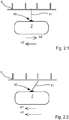
- Fig. 2.1 and Fig. 2.2 illustrate a respective cross section of the rack 5, the arm 7 and the washing liquid removing element 11 of the dishwasher illustrated in Fig. 1 .
- the arm 7 is illustrated as being moved in the second direction d2 by the arm moving arrangement.
- the washing liquid removing element 11 is arranged to touch the rack 5 upon movement of the arm 7 in the second direction d2.
- Fig. 2.2 the arm 7 is illustrated as being moved in the first direction d1 by the arm moving arrangement.
- the washing liquid removing element 11 has been displaced during the movement of the arm 7 in the first direction d1. Thereby, the washing liquid removing element 11 will cease from touching at least one of the rack 5 and the washing liquid at the rack 5.
- the arm moving arrangement may move the arm 7 in the second direction d2 during the drying phase of the dishwasher.
- washing liquid will effectively be removed from the rack 5 since the washing liquid removing element 11 is arranged to touch the rack 5 upon movement of the arm 7 in the second direction d2.
- the arm moving arrangement may move the arm 7 in the first direction d1 during a washing phase of the dishwasher.
- the arm moving arrangement is arranged to move the arm 7 at a first velocity v1 during a washing phase and at a second velocity v2 during a drying phase of the dishwasher 1, wherein the first velocity v1 is higher than the second velocity v2.
- the arm 7 is also illustrated as being moved at the second velocity v2 by the arm moving arrangement.
- the washing liquid removing element 11 is arranged to touch the rack 5 upon movement of the arm 7 at the second velocity v2.
- the arm 7 is also illustrated as being moved at the first velocity v1 by the arm moving arrangement.
- the washing liquid removing element 11 has been displaced during movement of the arm 7 at the first velocity v1.
- the washing liquid removing element 11 will cease from touching at least one of the rack 5 and the washing liquid at the rack 5 upon being displaced during movement of the arm 7 at the first velocity v1.
- the arm moving arrangement may move the arm 7 at the second velocity v2 during the drying phase of the dishwasher.
- washing liquid will effectively be removed from the rack 5 since the washing liquid removing element 11 is arranged to touch the rack 5 upon movement of the arm 7 at the second velocity v2
- the arm moving arrangement may move the arm 7 at the first velocity v1 during a washing phase of the dishwasher.
- resistance forces between the washing liquid removing element 11 and the rack 5 can be eliminated and noise caused by the washing liquid removing element 11 touching at least one of the rack 5 and the washing liquid at the rack 5 can be circumvented in a simple manner.
- the washing liquid removing element 11 is deformed during movement of the arm in the first direction d1, and/or at the first velocity v1, to cease from touching at least one of the rack 5 and the washing liquid at the rack 5. Such deformation may encompass a bending of the washing liquid removing element 11.
- the washing liquid removing element 11 may be deformed and/or displaced during movement of the arm 7 in the first direction d1 and/or at the first velocity v1 by resistance forces caused by air and/or washing liquid within the washing chamber, as well as centrifugal forces acting on the washing liquid removing element 11 during movement of the arm 7 in the first direction d1 and/or at the first velocity v1.
- the arm 7 comprises a guiding element 10, wherein the washing liquid removing element 11 is connected to the arm 7 via the guiding element 10.
- the guiding element 10 biases the washing liquid removing element 11 towards a position where the washing liquid removing element 11 touches at least one of the rack 5 and the washing liquid at the rack 5, below referred to as the touching position.
- the biasing force is in a direction essentially coinciding with the first direction d1.
- the guiding element 10 is arranged to prevent displacement of the washing liquid removing element 11 past the touching position in the first direction d1.
- resistance forces caused by air and/or washing liquid within the washing chamber will apply a force onto the washing liquid removing element 11 in the first direction d1.
- the resistance forces and the biasing force thus acts in the first direction d1 upon movement of the arm 7 in the second direction d2. Since the guiding element 10 is arranged to prevent displacement past the touching position in the first direction d1, the washing liquid removing element 11 will assume the touching position upon movement of the arm 7 in the second direction d2.
- Such touching position is illustrated in Fig. 2.1 .
- the guiding element 10 is arranged to bias the washing liquid removing element 11 with a biasing force less than the resistance forces applied to washing liquid removing element 11 upon movement of the arm 7 in the first direction d1.
- the resistance forces will displace the washing liquid removing element 11 to a position where the washing liquid removing element 11 ceases from touching at least one of the rack 5 and the washing liquid at the rack 5. Such a position is illustrated in Fig. 2.2 .
- Fig. 2.1 also illustrates the arm 7 as being moved at the second velocity v2
- Fig. 2.2 also illustrates the arm 7 is as being moved at the first velocity v1 by the arm moving arrangement, wherein the first velocity v1 is higher than the second velocity v2.
- the guiding element 10 biases the washing liquid removing element 11 towards a position where the washing liquid removing element 11 touches at least one of the rack 5 and the washing liquid at the rack 5.
- the biasing force is in a direction coinciding with a direction of movement of the arm 7 at the first velocity v1 and the second velocity v2.
- the biasing force and the first velocity v1 are configured such that the biasing force is less than the resistance forces upon movement of the arm 7 at the first velocity v1.
- the washing liquid removing arrangement 11 upon movement of the arm 7 at the first velocity v1, the washing liquid removing arrangement 11 will assume the position where the washing liquid removing element 11 ceases from touching at least one of the rack 5 and the washing liquid at the rack 5. Such position is illustrated in Fig. 2.2 .
- centrifugal forces will also apply a force onto the washing liquid removing element 11 upon movement of the arm 7 in the first direction d1, the second direction d2 as well as upon movement of the arm 7 at the first velocity v1 and the second velocity v2.
- the guiding element 10 may thus be arranged to guide the washing liquid removing element 11 in a manner corresponding to the above described, also based on centrifugal forces acting on the washing liquid removing element 11.
- the guiding element 10 is arranged to displace the washing liquid removing element 11 in a direction out from the arm 7, upon movement of the arm 7 in the second direction d2, and/or at the second velocity v2, to a position where the washing liquid removing element 11 touches at least one of the rack 5 and the washing liquid at the rack 5. And further, according to some embodiments, the guiding element 10 is arranged to displace the washing liquid removing element 11 in a direction towards the arm 7, upon movement of the arm 7 in the first direction d1 and/or at the first velocity v1, to a position where the washing liquid removing element 11 ceases from touching at least one of the rack 5 and the washing liquid at the rack 5.
- the dishwasher 1 may comprise a control unit arranged to control the arm moving arrangement 9 to move the arm 7 in the first direction d1 during the washing phase and in the second direction d2 during the drying phase.
- control unit may, according to some embodiments, be arranged to control the arm moving arrangement 9 to move the arm 7 at the first velocity v1 during the washing phase and at the second velocity v2 during the drying phase.
- the washing liquid removing element 11 may comprise a non-absorbing material such as rubber, silicon, thermoplastic elastomer (TPE), metal or the like. As a result, the at least one washing liquid removing element 11 will wipe the washing liquid from the rack 5, rather than absorbing it.
- TPE thermoplastic elastomer
- the arm 7 comprises a plurality of washing liquid removing elements 11 arranged to touch at least one of the rack 5 and the washing liquid at the rack 5 upon movement of the arm 7 to remove washing liquid from the rack 5.
- Each of the washing liquid removing elements 11 may be formed as an elongated solid- or hollow rod with for example a circular cross-section.
- the dishwasher 1 may comprise a second rack 17 adapted to accommodate items to be washed by washing liquid within the washing chamber 3. Further, the dishwasher 1 may comprise a second arm 19, and a second arm moving arrangement 21 arranged to move the second arm 19 within the washing chamber 3.
- the second arm 19 may comprise at least one second washing liquid removing element 23 arranged to touch at least one of the second rack 17 and washing liquid at the second rack 17 upon movement of the second arm 19 to remove the washing liquid from the second rack 17.
- the second rack 17, the second arm 19, the second arm moving arrangement 21 and the at least one second washing liquid removing element 23 may correspond to embodiments of the rack 5, the arm 7, the arm moving arrangement 9 and the at least one washing liquid removing element 11, as described above.
- Fig. 3 illustrates a method 100 for removing washing liquid from a rack of a dishwasher comprising a washing chamber, a rack adapted to accommodate items to be washed by washing liquid within the washing chamber, an arm and an arm moving arrangement, wherein the arm comprises at least one washing liquid removing element, and where the method 100 comprises:
- the method 100 may comprise:
- the method 100 may comprise:
Landscapes
- Washing And Drying Of Tableware (AREA)
- Cleaning By Liquid Or Steam (AREA)
Description
- The present disclosure relates to a dishwasher and a method for removing washing liquid from a rack of a dishwasher.
- Today's dishwashers are expected to perform high quality wash of dishware, and environmental concerns require an efficient use of energy during operation. Also, it is an advantage if washed items are dry after a washing phase. In the last phase of a wash cycle, water is sprayed in to the dishwasher in order to rinse the washed items. After stopping, the remaining water will form drops and pools on the washed items and at the racks. The drops are held on surfaces due to the surface tension in the droplets and are hanging from washed items, racks and places where the washed items and racks meet each other. The water will slowly evaporate and the size of the drops will gradually be reduced. In the last phase of a wash cycle, warm water may be sprayed in to the dishwasher in order to heat the washed items. In addition, modern dishwashers may use heat during a drying phase to dry the washed items, for example by having heaters within the dishwasher and/or by blowing warm air inside the dishwasher. One problem is that the use of heat during a drying phase requires a large amount of energy. Further, such drying process using heat is time consuming.
- Attempts have been made to reduce energy consumption during a drying phase of a dishwasher. The document
FR2879429 A1 -
EP 2 233 057 A1 - An object of the embodiments herein is to provide an improved dishwasher that eliminates or at least reduces the problems and/or drawbacks associated with the prior art solutions.
- According to an aspect of the invention, the object is achieved by a dishwasher comprising a washing chamber, a rack adapted to accommodate items to be washed by washing liquid within the washing chamber, an arm, and an arm moving arrangement arranged to move the arm within the washing chamber, wherein the arm comprises at least one washing liquid removing element arranged to touch at least one of the rack and washing liquid at the rack upon movement of the arm, to remove the washing liquid from the rack.
- Since the arm comprises at least one washing liquid removing element arranged to touch at least one of the rack and washing liquid at the rack upon movement of the arm, the washing liquid at the rack, will be removed simply by touching at least one of the rack and washing liquid at the rack by the at least one washing liquid removing element. In addition, since the rack is adapted to accommodate items to be washed by washing liquid, the at least one washing liquid removing element may also touch the items to be washed by washing liquid. As a result, the washing liquid will be removed from the rack and/or from the items to be washed in a simple and an efficient manner. Thus, during a drying phase of the dishwasher, less time and energy is required in order to evaporate washing liquid, since there is less washing liquid to evaporate. Further, the washing liquid will be effectively removed without the need of vibrating of the racks of the dishwasher. Thereby, less noise will be generated than the above described solution. Accordingly, an improved dishwasher is provided.
- As a result, the above mentioned object is achieved.
- Optionally, the arm is a wash arm provided with at least one spray nozzle for spraying washing liquid into the washing chamber to wash the items to be washed by the washing liquid. Thereby, an already existing wash arm of the dishwasher comprises the at least one washing liquid removing element. As a result, the washing liquid may be removed in a simple and efficient manner while production cost of the dishwasher provided may be kept low.
- Optionally, the movement is a rotational movement. Thereby, the arm may be moved in a simple manner.
- Optionally, the arm moving arrangement comprises a motor arranged to move the arm. Since the arm moving arrangement comprises a motor arranged to move the arm, the movement of the arm may be controlled in a simple manner. In addition, the arm may be moved in a predetermined manner to ensure an effective removing of the washing liquid from the rack. Further, the arm may be moved without need for water or air to be sprayed through the spray nozzles.
- Optionally, the at least one washing liquid removing element is resilient. Thereby, the at least one washing liquid removing element may touch at least one of the rack and washing liquid at the rack in a smooth manner upon movement of the arm. Since the at least one washing liquid removing element may touch at least one of the rack and washing liquid at the rack in a smooth manner, resistance forces between the at least one washing liquid removing element and the rack may further be reduced. As a result, vibrations and noise may be further circumvented.
- Optionally, the arm moving arrangement is arranged to move the arm during at least a drying phase of the dishwasher. Thus, the washing liquid may be removed from the rack and/or from the items to be washed in a simple and an efficient manner during at least the drying phase of the dishwasher, which will shorten the drying process of the dishwasher.
- Optionally, the at least one washing liquid removing element is arranged to touch at least one of the rack and the washing liquid at the rack only during the drying phase. Since the at least one washing liquid removing element is arranged to touch at least one of the rack and the washing liquid at the rack only during the drying phase, the at least one washing liquid removing element is arranged to cease from touching at least one of the rack and the washing liquid at the rack during a washing phase of the dishwasher. Thereby, resistance forces between the at least one washing liquid removing element and the rack during the washing phase will be eliminated. Further, noise caused by the at least one washing liquid removing element touching at least one of the rack and the washing liquid at the rack during the washing phase will be circumvented. Even further, wear and tear of the at least one washing liquid removing element is reduced.
- Optionally, the arm is a wash arm, and wherein the arm moving arrangement is arranged to move the arm in a first direction during a washing phase, and in a second direction during a drying phase of the dishwasher, wherein the first direction is opposite to the second direction, and wherein the at least one washing liquid removing element is arranged to touch at least one of the rack and the washing liquid at the rack upon movement of the arm in the second direction, and wherein the at least one washing liquid removing element is arranged to be at least one of deformed and displaced during movement of the arm in the first direction, and is arranged to cease from touching at least one of the rack and the washing liquid at the rack upon being at least one of deformed and displaced during movement of the arm in the first direction. Thereby, resistance forces between the at least one washing liquid removing element and the rack during the washing phase are eliminated in a simple manner by moving the arm in the first direction during the washing phase. Likewise, washing liquid is effectively removed from the rack in a simple manner by moving the arm in the second direction during the drying phase. Further, noise caused by the at least one element touching at least one of the rack and the washing liquid at the rack during the washing phase is circumvented in a simple manner. Even further, wear and tear of the at least one washing liquid removing element is reduced in a simple manner. As a result, an improved dishwasher is provided.
- Optionally, the arm is a wash arm, and the arm moving arrangement is arranged to move the arm at a first velocity during a washing phase and at a second velocity during a drying phase of the dishwasher, wherein the first velocity is higher than the second velocity, and wherein the at least one washing liquid removing element is arranged to touch at least one of the rack and the washing liquid at the rack upon movement of the arm at the second velocity, and wherein the at least one washing liquid removing element is arranged to be at least one of deformed and displaced during movement of the arm at the first velocity, and is arranged to cease from touching at least one of the rack and the washing liquid at the rack upon being at least one of deformed and displaced during movement of the arm at the first velocity. Thereby, resistance forces between the at least one washing liquid removing element and the rack during the washing phase are eliminated in a simple manner by moving the arm at the first velocity during the washing phase. Likewise, washing liquid is effectively removed from the rack in a simple manner by moving the arm at the second velocity during the drying phase. Further, noise caused by the at least one element touching at least one of the rack and the washing liquid at the rack during the washing phase is circumvented in a simple manner. Even further, wear and tear of the at least one washing liquid removing element is reduced in a simple manner. As a result, an improved dishwasher is provided.
- Optionally, the at least one washing liquid removing element comprises a non-absorbing material Since the at least one washing liquid removing element comprises a non-absorbing material, the at least one washing liquid removing element will wipe the washing liquid from the rack, rather than absorbing it. As a result, a greater amount of washing liquid will end up at a bottom of the dishwasher wherefrom the washing liquid efficiently may be transported away from the dishwasher, for example by a pump to a drain. Further, since the at least one washing liquid removing element comprises a non-absorbing material, it will not hold washing liquid after use which may prolong the lifespan of the at least one washing liquid removing element.
- Optionally, the arm comprises a plurality of washing liquid removing elements arranged to touch at least one of the rack and the washing liquid at the rack upon movement of the arm to remove washing liquid from the rack. Thereby, an even more efficient removing of washing liquid is provided.
- Further embodiments herein aim to provide an improved method for removing liquid from a rack of a dishwasher, eliminating or at least reducing the problems and/or drawbacks associated with prior art solutions.
- According to some embodiments, this is provided by a method for removing washing liquid from a rack of a dishwasher comprising a washing chamber, a rack adapted to accommodate items to be washed by washing liquid within the washing chamber, an arm and an arm moving arrangement, wherein the arm comprises at least one washing liquid removing element and wherein the method comprises:
- moving the arm within the washing chamber, using the arm moving arrangement, and
- removing washing liquid from the rack by touching at least one of the rack and washing liquid at the rack upon the movement of the arm, using the at least one washing liquid removing element.
- Since, the method comprises removing washing liquid from the rack by touching at least one of the rack and washing liquid at the rack upon the movement of the arm, using the at least one washing liquid removing element, the washing liquid will be effectively removed which will shorten a drying process of the dishwasher. Thus, the time and the energy needed to evaporate the washing liquid will be reduced. Further, the washing liquid will be effectively removed without need of vibrating of the racks of the dishwasher. Thereby, less noise will be produced than according to prior art solutions. Accordingly, an improved method for removing liquid from a rack of a dishwasher is provided.
- Accordingly, a method for removing liquid from a rack of a dishwasher is provided which eliminates or at least reduces the problems and/or drawbacks associated with prior art solutions.
- As a result, the above mentioned object is achieved.
- Optionally, the arm is a wash arm and the method may comprise:
- moving the arm in a first direction during a washing phase of the dishwasher, using the arm moving arrangement, wherein the at least one washing liquid removing element is arranged to be at least one of deformed and displaced during movement of the arm in the first direction, and wherein the at least one washing liquid removing element is arranged to cease from touching at least one of the rack and the washing liquid at the rack upon being at least one of deformed and displaced during movement of the arm in the first direction,
- moving the arm in a second direction during a drying phase of the dishwasher, using the arm moving arrangement, wherein the first direction is opposite to the second direction, and
- removing the washing liquid from the rack by touching at least one of the rack and washing liquid at the rack upon movement of the arm in the second direction.
- Thereby, resistance forces between the at least one washing liquid removing element and the rack during the washing phase is eliminated in a simple manner by moving the arm in the first direction during the washing phase. Since the resistance forces between the at least one washing liquid removing element and the rack during the washing phase are eliminated, also noise caused by the at least one element touching at least one of the rack and the washing liquid at the rack during the washing phase is circumvented in a simple manner by moving the arm in the first direction. In addition, wear and tear of the at least one washing liquid removing element is reduced in a simple manner.
- Further, washing liquid can be effectively removed from the rack simply by moving the arm in the second direction during the drying phase of the dishwasher. Thereby, an improved method for removing washing liquid is provided.
- Optionally, the arm is a wash arm and the method may comprise:
- moving the arm at a first velocity during a washing phase of the dishwasher, using the arm moving arrangement, wherein the at least one washing liquid removing element is arranged to be at least one of deformed and displaced during movement of the arm at the first velocity, and wherein the at least one washing liquid removing element is arranged to cease from touching at least one of the rack and the washing liquid at the rack upon being at least one of deformed and displaced during movement of the arm at the first velocity,
- moving the arm at a second velocity during a drying phase of the dishwasher, using the arm moving arrangement, wherein the first velocity is higher than the second velocity,
- and removing the washing liquid from the rack by touching at least one of the rack and washing liquid at the rack upon movement of the arm at the second velocity.
- Thereby resistance forces between the at least one washing liquid removing element and the rack during the washing phase are eliminated in a simple manner by moving the arm at the first velocity during the washing phase. Since the resistance forces between the at least one washing liquid removing element and the rack during the washing phase are eliminated, also noise caused by the at least one element touching at least one of the rack and the washing liquid at the rack during the washing phase is circumvented in a simple manner by moving the arm at the first velocity.
- Further, washing liquid will be effectively removed from the rack simply by moving the arm at the second velocity during the drying phase of the dishwasher. Thereby, an improved method for removing washing liquid is provided.
- Further features of, and advantages with, the present invention will become apparent when studying the appended claims and the following detailed description. Those skilled in the art will realize that the different features described may be combined to create embodiments other than those described in the following, without departing from the scope of the present invention, as defined by the appended claims.
- The various aspects of the invention, including its particular features and advantages, will be readily understood from the following detailed description and the accompanying drawings, in which;
-
Fig. 1 illustrates a dishwasher according to some embodiments, -
Fig. 2.1 and Fig. 2.2 illustrate a respective cross section of a rack, an arm and a washing liquid removing element according to some embodiments of the dishwasher illustrated inFig. 1 , and -
Fig. 3 illustrates a method for removing washing liquid from a rack of a dishwasher according to some embodiments. - The embodiments herein will now be described more fully with reference to the accompanying drawings. Like numbers refer to like elements throughout.
-
Fig. 1 illustrates adishwasher 1 comprising awashing chamber 3, arack 5 adapted to accommodateitems 2 to be washed by washing liquid within thewashing chamber 3, anarm 7, and anarm moving arrangement 9 arranged to move thearm 7 within thewashing chamber 3. As illustrated inFig. 1 , thearm 7 comprises at least one washingliquid removing element 11 arranged to touch at least one of therack 5 and washing liquid at therack 5 upon movement of thearm 7, to remove the washing liquid from therack 5. Thereby, the washing liquid at therack 5 will effectively be removed. As a result, a drying process of the dishwasher can be shortened since the time and the energy needed to evaporate the washing liquid during such drying phase will be reduced. - According to the embodiments illustrated in
Fig. 1 , thedishwasher 1 is configured to perform a washing phase for washing theitems 2, and a drying phase for drying theitems 2. When starting the washing phase, the washing liquid is delivered to thedishwasher 1 to be warmed up and then sprayed into thewashing chamber 3. The washing liquid used during the washing phase is collected at thebottom 6 of thedishwasher 1 and then pumped to thearm 7 using awashing liquid pump 4 andducts 8. When the washing phase is finished, the washing liquid is pumped out from the dishwasher to a drain. After the washing phase, some of the washing liquid may still remain within thewashing chamber 3 in the form of drops and pools at therack 5 and at theitems 2. The drops will remain at therack 5 and at theitems 2 due to surface tension of the drops. Since the at least one washingliquid removing element 11 is arranged to touch at least one of therack 5 and washing liquid at therack 5 upon movement of thearm 7, such drops are effectively removed from therack 5. After being removed, the washing liquid can be collected at thebottom 6 of thedishwasher 1 and then pumped to a drain using thewashing liquid pump 4. As a result, energy needed to evaporate the washing liquid will be reduced, and the drying process of thedishwasher 1 can be shortened, since there is less washing liquid to evaporate. - According to the embodiments illustrated in
Fig. 1 , thearm 7 is a wash arm provided with at least onespray nozzle 13 for spraying the washing liquid into thewashing chamber 3 to wash theitems 2 to be washed by the washing liquid. Thearm 7 may be arranged below therack 5 at a distance enabling an effective washing ofitems 2 accommodated in therack 5. The washing of theitems 2 is performed by spraying washing liquid into thewashing chamber 3 through the least onespray nozzle 13 to wash theitems 2 to be washed by the washing liquid. As illustrated inFig. 1 , the wash arm may be provided withseveral spray nozzles 13 for spraying the washing liquid into thewashing chamber 3 to wash theitems 2 to be washed by the washing liquid. - According to the embodiments illustrated in
Fig.1 , the movement of thearm 7 is a rotational movement and thearm 7 is arranged to rotate around an arm rotation axle r. However, according to some embodiments, the movement ofarm 7 may be a linear movement of thearm 7, such as a back and forth movement along therack 5. - The
arm moving arrangement 9 may comprise amotor 15, such as an electric motor, arranged to move thearm 7. Thereby, the movement of thearm 7 may be controlled in a simple and predetermined manner to ensure an effective removing of the washing liquid from therack 5 using the at least one washingliquid removing element 11. In addition, thearm 7 can be moved during the drying phase of thedishwasher 1 without need for water to be sprayed through thespray nozzles 13. According to further embodiments, thearm moving arrangement 9 may comprise an air pump and ducts, where the air pump is connected to the at least onespray nozzle 13, or other apertures, of thearm 7 via the ducts, and wherein the air pump is arranged to pump air to at least onespray nozzle 13, or other apertures, to move thearm 7 using air flowing through the at least onespray nozzle 13, or other apertures, of thearm 7. - According to some embodiments, the at least one washing
liquid removing element 11 is resilient. Thereby, the at least one washingliquid removing element 11 will touch at least one of therack 5 and washing liquid at therack 5 in a smooth manner upon movement of thearm 7. Thereby, the touching will produce less noise. According to the embodiments illustrated inFig. 1 , the washingliquid removing element 11 is formed as an elongated rod or pin. In further embodiments, the washingliquid removing element 11 may be formed as a brush. The washingliquid removing element 11 may comprise an elastic material such as a polymer or an elastomer. The washingliquid removing element 11 may further comprise a metallic material. - The
arm moving arrangement 9 may be arranged to move thearm 7 during at least a drying phase of thedishwasher 1. Thus, the washing liquid may be removed from therack 5, and/or from theitems 2 to be washed, in a simple and efficient manner during the drying phase of thedishwasher 1, which will shorten the drying process of the dishwasher. - According to some embodiments, the at least one washing
liquid removing element 11 is arranged to touch at least one of therack 5 and the washing liquid at therack 5 only during the drying phase. In such embodiments, the at least one washingliquid removing element 11 is arranged not to touch at least one of therack 5 and the washing liquid at therack 5 during a washing phase of thedishwasher 1. Thereby, existence of resistance forces between the at least one washingliquid removing element 11 and therack 5 can be circumvented during the washing phase and noise during the washing phase may be kept low in a simple manner. - According to some embodiments, the
arm 7 is a wash arm and thearm moving arrangement 9 is arranged to move thearm 7 in a first direction d1 during a washing phase of thedishwasher 1, and in a second direction d2 during a drying phase of thedishwasher 1, wherein the first direction d1 is opposite to the second direction d2.Fig. 2.1 and Fig. 2.2 illustrate a respective cross section of therack 5, thearm 7 and the washingliquid removing element 11 of the dishwasher illustrated inFig. 1 . InFig. 2.1 thearm 7 is illustrated as being moved in the second direction d2 by the arm moving arrangement. As can be seen, in the embodiments illustrated, the washingliquid removing element 11 is arranged to touch therack 5 upon movement of thearm 7 in the second direction d2. - In
Fig. 2.2 , thearm 7 is illustrated as being moved in the first direction d1 by the arm moving arrangement. As can be seen, the washingliquid removing element 11 has been displaced during the movement of thearm 7 in the first direction d1. Thereby, the washingliquid removing element 11 will cease from touching at least one of therack 5 and the washing liquid at therack 5. - Accordingly, the arm moving arrangement may move the
arm 7 in the second direction d2 during the drying phase of the dishwasher. As a result, washing liquid will effectively be removed from therack 5 since the washingliquid removing element 11 is arranged to touch therack 5 upon movement of thearm 7 in the second direction d2. - Further, the arm moving arrangement may move the
arm 7 in the first direction d1 during a washing phase of the dishwasher. As a result, resistance forces between the washingliquid removing element 11 and therack 5 can be eliminated, and noise caused by the washingliquid removing element 11 touching at least one of therack 5 and the washing liquid at therack 5 can be circumvented in a simple manner. - Thus, these functions and advantages can be achieved simply by moving the
arm 7 in the first direction d1 and in the second direction d2. - According to some embodiments, the arm moving arrangement is arranged to move the
arm 7 at a first velocity v1 during a washing phase and at a second velocity v2 during a drying phase of thedishwasher 1, wherein the first velocity v1 is higher than the second velocity v2. - In
Fig. 2.1 , thearm 7 is also illustrated as being moved at the second velocity v2 by the arm moving arrangement. As can be seen, in the embodiments illustrated, the washingliquid removing element 11 is arranged to touch therack 5 upon movement of thearm 7 at the second velocity v2. - In
Fig. 2.2 , thearm 7 is also illustrated as being moved at the first velocity v1 by the arm moving arrangement. As can be seen, the washingliquid removing element 11 has been displaced during movement of thearm 7 at the first velocity v1. Thereby, the washingliquid removing element 11 will cease from touching at least one of therack 5 and the washing liquid at therack 5 upon being displaced during movement of thearm 7 at the first velocity v1. - Accordingly, the arm moving arrangement may move the
arm 7 at the second velocity v2 during the drying phase of the dishwasher. As a result, washing liquid will effectively be removed from therack 5 since the washingliquid removing element 11 is arranged to touch therack 5 upon movement of thearm 7 at the second velocity v2
Further, the arm moving arrangement may move thearm 7 at the first velocity v1 during a washing phase of the dishwasher. As a result, resistance forces between the washingliquid removing element 11 and therack 5 can be eliminated and noise caused by the washingliquid removing element 11 touching at least one of therack 5 and the washing liquid at therack 5 can be circumvented in a simple manner. - Thus, these functions and advantages can be achieved simply by moving the
arm 7 at the first velocity v1 and at the second velocity v2. - According to some embodiments, the washing
liquid removing element 11 is deformed during movement of the arm in the first direction d1, and/or at the first velocity v1, to cease from touching at least one of therack 5 and the washing liquid at therack 5. Such deformation may encompass a bending of the washingliquid removing element 11. The washingliquid removing element 11 may be deformed and/or displaced during movement of thearm 7 in the first direction d1 and/or at the first velocity v1 by resistance forces caused by air and/or washing liquid within the washing chamber, as well as centrifugal forces acting on the washingliquid removing element 11 during movement of thearm 7 in the first direction d1 and/or at the first velocity v1. - According to some embodiments, as illustrated in
Fig. 2.1 and Fig 2.2 , thearm 7 comprises a guidingelement 10, wherein the washingliquid removing element 11 is connected to thearm 7 via the guidingelement 10. In the embodiments illustrated, the guidingelement 10 biases the washingliquid removing element 11 towards a position where the washingliquid removing element 11 touches at least one of therack 5 and the washing liquid at therack 5, below referred to as the touching position. The biasing force is in a direction essentially coinciding with the first direction d1. The guidingelement 10 is arranged to prevent displacement of the washingliquid removing element 11 past the touching position in the first direction d1. Upon movement of thearm 7 in the second direction d2, as is illustrated inFig. 2.1 , resistance forces caused by air and/or washing liquid within the washing chamber will apply a force onto the washingliquid removing element 11 in the first direction d1. The resistance forces and the biasing force thus acts in the first direction d1 upon movement of thearm 7 in the second direction d2. Since the guidingelement 10 is arranged to prevent displacement past the touching position in the first direction d1, the washingliquid removing element 11 will assume the touching position upon movement of thearm 7 in the second direction d2. Such touching position is illustrated inFig. 2.1 . - Upon movement of the
arm 7 in the first direction d1, as is illustrated inFig. 2.2 , resistance forces caused by air and/or washing liquid within the washing chamber will apply a force onto the washingliquid removing element 11 in the second direction d2. The guidingelement 10 is arranged to bias the washingliquid removing element 11 with a biasing force less than the resistance forces applied to washingliquid removing element 11 upon movement of thearm 7 in the first direction d1. As a result, upon movement of thearm 7 in the first direction d1, the resistance forces will displace the washingliquid removing element 11 to a position where the washingliquid removing element 11 ceases from touching at least one of therack 5 and the washing liquid at therack 5. Such a position is illustrated inFig. 2.2 . - As referred to above,
Fig. 2.1 also illustrates thearm 7 as being moved at the second velocity v2, andFig. 2.2 also illustrates thearm 7 is as being moved at the first velocity v1 by the arm moving arrangement, wherein the first velocity v1 is higher than the second velocity v2. Also in these embodiments, the guidingelement 10 biases the washingliquid removing element 11 towards a position where the washingliquid removing element 11 touches at least one of therack 5 and the washing liquid at therack 5. The biasing force is in a direction coinciding with a direction of movement of thearm 7 at the first velocity v1 and the second velocity v2. Upon movement of thearm 7 at the first velocity v1 and at the second velocity v2, resistance forces caused by air and/or washing liquid within the washing chamber will apply a force onto the washingliquid removing element 11 in a direction opposite to the direction of movement. The biasing force and the second velocity v2 are configured such that the biasing force is greater than the resistance forces upon movement of thearm 7 at the second velocity v2. As a result, upon movement of thearm 7 at the second velocity v2, the washingliquid removing arrangement 11 will assume the position where the washingliquid removing element 11 touches at least one of therack 5 and the washing liquid at therack 5. Such position is illustrated inFig. 2.1 . - The biasing force and the first velocity v1 are configured such that the biasing force is less than the resistance forces upon movement of the
arm 7 at the first velocity v1. As a result, upon movement of thearm 7 at the first velocity v1, the washingliquid removing arrangement 11 will assume the position where the washingliquid removing element 11 ceases from touching at least one of therack 5 and the washing liquid at therack 5. Such position is illustrated inFig. 2.2 . - In addition to resistance forces caused by air and/or washing liquid within the washing chamber, centrifugal forces will also apply a force onto the washing
liquid removing element 11 upon movement of thearm 7 in the first direction d1, the second direction d2 as well as upon movement of thearm 7 at the first velocity v1 and the second velocity v2. The guidingelement 10 may thus be arranged to guide the washingliquid removing element 11 in a manner corresponding to the above described, also based on centrifugal forces acting on the washingliquid removing element 11. - According to some embodiments, the guiding
element 10 is arranged to displace the washingliquid removing element 11 in a direction out from thearm 7, upon movement of thearm 7 in the second direction d2, and/or at the second velocity v2, to a position where the washingliquid removing element 11 touches at least one of therack 5 and the washing liquid at therack 5. And further, according to some embodiments, the guidingelement 10 is arranged to displace the washingliquid removing element 11 in a direction towards thearm 7, upon movement of thearm 7 in the first direction d1 and/or at the first velocity v1, to a position where the washingliquid removing element 11 ceases from touching at least one of therack 5 and the washing liquid at therack 5. - The
dishwasher 1 may comprise a control unit arranged to control thearm moving arrangement 9 to move thearm 7 in the first direction d1 during the washing phase and in the second direction d2 during the drying phase. Such control unit may, according to some embodiments, be arranged to control thearm moving arrangement 9 to move thearm 7 at the first velocity v1 during the washing phase and at the second velocity v2 during the drying phase. - The washing
liquid removing element 11 may comprise a non-absorbing material such as rubber, silicon, thermoplastic elastomer (TPE), metal or the like. As a result, the at least one washingliquid removing element 11 will wipe the washing liquid from therack 5, rather than absorbing it. - According to the embodiments illustrated in
Fig. 1 , thearm 7 comprises a plurality of washingliquid removing elements 11 arranged to touch at least one of therack 5 and the washing liquid at therack 5 upon movement of thearm 7 to remove washing liquid from therack 5. Each of the washingliquid removing elements 11 may be formed as an elongated solid- or hollow rod with for example a circular cross-section. - As illustrated in
Fig.1 , thedishwasher 1 may comprise asecond rack 17 adapted to accommodate items to be washed by washing liquid within thewashing chamber 3. Further, thedishwasher 1 may comprise asecond arm 19, and a secondarm moving arrangement 21 arranged to move thesecond arm 19 within thewashing chamber 3. Thesecond arm 19 may comprise at least one second washingliquid removing element 23 arranged to touch at least one of thesecond rack 17 and washing liquid at thesecond rack 17 upon movement of thesecond arm 19 to remove the washing liquid from thesecond rack 17. Thesecond rack 17, thesecond arm 19, the secondarm moving arrangement 21 and the at least one second washingliquid removing element 23 may correspond to embodiments of therack 5, thearm 7, thearm moving arrangement 9 and the at least one washingliquid removing element 11, as described above. -
Fig. 3 illustrates amethod 100 for removing washing liquid from a rack of a dishwasher comprising a washing chamber, a rack adapted to accommodate items to be washed by washing liquid within the washing chamber, an arm and an arm moving arrangement, wherein the arm comprises at least one washing liquid removing element, and where themethod 100 comprises: - moving 110 the arm within the washing chamber, using the arm moving arrangement, and
- removing 120 washing liquid from the rack by touching at least one of the rack and washing liquid at the rack upon the movement of the arm, using the at least one washing liquid removing element.
- As illustrated in
Fig. 3 , themethod 100 may comprise: - moving 111 the arm in a first direction during a washing phase of the dishwasher, using the arm moving arrangement, wherein the at least one washing liquid removing element is arranged to be at least one of deformed and displaced during movement of the arm in the first direction, and wherein the at least one washing liquid removing element is arranged to cease from touching at least one of the rack and the washing liquid at the rack upon being at least one of deformed and displaced during movement of the arm in the first direction,
- moving 112 the arm in a second direction during a drying phase of the dishwasher, using the arm moving arrangement, wherein the first direction is opposite to the second direction, and
- removing 121 the washing liquid from the rack by touching at least one of the rack and washing liquid at the rack upon movement of the arm in the second direction.
- As illustrated in
Fig. 3 , themethod 100 may comprise: - moving 113 the arm at a first velocity during a washing phase of the dishwasher, using the arm moving arrangement, wherein the at least one washing liquid removing element is arranged to be at least one of deformed and displaced during movement of the arm at the first velocity, and wherein the at least one washing liquid removing element is arranged to cease from touching at least one of the rack and the washing liquid at the rack upon being at least one of deformed and displaced during movement of the arm at the first velocity,
- moving 114 the arm at a second velocity during a drying phase of the dishwasher, using the arm moving arrangement, wherein the first velocity is higher than the second velocity, and
- removing 122 the washing liquid from the rack by touching at least one of the rack and washing liquid at the rack upon movement of the arm at the second velocity.
Claims (14)
- A dishwasher (1) comprising a washing chamber (3), a rack (5) adapted to accommodate items (2) to be washed by washing liquid within said washing chamber (3), an arm (7), and an arm moving arrangement (9) arranged to move said arm (7) within said washing chamber (3),
characterized in that said arm (7) comprises at least one washing liquid removing element (11) arranged to touch at least one of said rack (5) and washing liquid at said rack (5) upon movement of said arm (7) to remove said washing liquid from said rack (5). - The dishwasher (1) according to claim 1, wherein said arm (7) is a wash arm provided with at least one spray nozzle (13) for spraying washing liquid into said washing chamber (3) to wash said items (2) to be washed by said washing liquid.
- The dishwasher (1) according to claim 1 or 2, wherein said movement is a rotational movement.
- The dishwasher (1) according to any one of the preceding claims, wherein said arm moving arrangement (9) comprises a motor (15) arranged to move said arm (7).
- The dishwasher (1) according to any one of the preceding claims, wherein said at least one washing liquid removing element (11) is resilient.
- The dishwasher (1) according to any one of the preceding claims, wherein said arm moving arrangement (9) is arranged to move said arm (7) during at least a drying phase of said dishwasher (1).
- The dishwasher (1) according to claim 6, wherein said at least one washing liquid removing element (11) is arranged to touch at least one of said rack (5) and said washing liquid at said rack (5) only during said drying phase.
- The dishwasher (1) according to any one of the preceding claims, wherein said arm (7) is a wash arm, and wherein said arm moving arrangement (9) is arranged to move said arm (7) in a first direction (d1) during a washing phase, and in a second direction (d2) during a drying phase of said dishwasher (1), wherein said first direction (d1) is opposite to said second direction (d2), and wherein said at least one washing liquid removing element (11) is arranged to touch at least one of said rack (5) and said washing liquid at said rack (5) upon movement of said arm (7) in said second direction (d2), and wherein said at least one washing liquid removing element (11) is arranged to be at least one of deformed and displaced during movement of said arm (7) in said first direction (d1), and is arranged to cease from touching at least one of said rack (5) and said washing liquid at said rack (5) upon being at least one of deformed and displaced during movement of said arm (7) in said first direction (d1).
- The dishwasher (1) according to any one of the preceding claims, wherein said arm (7) is a wash arm, and wherein said arm moving arrangement (9) is arranged to move said arm (7) at a first velocity (v1) during a washing phase, and at a second velocity (v2) during a drying phase of said dishwasher (1), wherein said first velocity (v1) is higher than said second velocity (v2), and wherein said at least one washing liquid removing element (11) is arranged to touch at least one of said rack (5) and said washing liquid at said rack (5) upon movement of said arm (7) at said second velocity (v2), and wherein said at least one washing liquid removing element (11) is arranged to be at least one of deformed and displaced during movement of said arm (7) at said first velocity (v1), and is arranged to cease from touching at least one of said rack (5) and said washing liquid at said rack (5) upon being at least one of deformed and displaced during movement of said arm (7) at said first velocity (v1).
- The dishwasher (1) according to any one of the preceding claims, wherein said at least one washing liquid removing element (11) comprises a non-absorbing material.
- The dishwasher (1) according to any one of the preceding claims, wherein said arm (7) comprises a plurality of washing liquid removing elements (11) arranged to touch at least one of said rack (5) and said washing liquid at said rack (5) upon movement of said arm (7) to remove washing liquid from said rack (5).
- A method (100) for removing washing liquid from a rack (5) of a dishwasher (1) comprising a washing chamber (3), a rack (5) adapted to accommodate items (2) to be washed by washing liquid within said washing chamber (3), an arm (7) and an arm moving arrangement (9), wherein said arm (7) comprises at least one washing liquid removing element (11) and wherein said method comprises:- moving (110) said arm (7) within said washing chamber (3), using said arm moving arrangement (9), and- removing (120) washing liquid from said rack (5) by touching at least one of said rack (5) and washing liquid at said rack (5) upon said movement of said arm (7), using said at least one washing liquid removing element (11).
- The method (100) according to claim 12, wherein said arm (7) is a wash arm and wherein said method (100) comprises:- moving (111) said arm (7) in a first direction (d1) during a washing phase of said dishwasher (1), using said arm moving arrangement (9), wherein said at least one washing liquid removing element (11) is arranged to be at least one of deformed and displaced during movement of said arm (7) in said first direction (d1), and wherein said at least one washing liquid removing element (11) is arranged to cease from touching at least one of said rack (5) and said washing liquid at said rack (5) upon being at least one of deformed and displaced during movement of said arm (7) in said first direction (d1),- moving (112) said arm (7) in a second direction (d2) during a drying phase of said dishwasher (1), using said arm moving arrangement (9), wherein said first direction (d1) is opposite to said second direction (d2), and- removing (121) said washing liquid from said rack (5) by touching at least one of said rack (5) and washing liquid at said rack (5) upon movement of said arm (7) in said second direction (d2).
- The method (100) according to claim 12 or 13, wherein said arm (7) is a wash arm and wherein said method (100) comprises:- moving (113) said arm (7) at a first velocity (v1) during a washing phase of said dishwasher (1), using said arm moving arrangement (9), wherein said at least one washing liquid removing element (11) is arranged to be at least one of deformed and displaced during movement of said arm (7) at said first velocity (v1), and wherein said at least one washing liquid removing element (11) is arranged to cease from touching at least one of said rack (5) and said washing liquid at said rack (5) upon being at least one of deformed and displaced during movement of said arm (7) at said first velocity (v1),- moving (114) said arm (7) at a second velocity (v2) during a drying phase of said dishwasher (1), using said arm moving arrangement (9), wherein said first velocity (v1) is higher than said second velocity (v2), and- removing (122) said washing liquid from said rack (5) by touching at least one of said rack (5) and washing liquid at said rack (5) upon movement of said arm (7) at said second velocity (v2).
Priority Applications (1)
| Application Number | Priority Date | Filing Date | Title |
|---|---|---|---|
| PL15794925T PL3376932T3 (en) | 2015-11-16 | 2015-11-16 | A dishwasher and a method for removing washing liquid from a rack of a dishwasher |
Applications Claiming Priority (1)
| Application Number | Priority Date | Filing Date | Title |
|---|---|---|---|
| PCT/EP2015/076698 WO2017084693A1 (en) | 2015-11-16 | 2015-11-16 | A dishwasher and a method for removing washing liquid from a rack of a dishwasher |
Publications (2)
| Publication Number | Publication Date |
|---|---|
| EP3376932A1 EP3376932A1 (en) | 2018-09-26 |
| EP3376932B1 true EP3376932B1 (en) | 2019-08-14 |
Family
ID=54545148
Family Applications (1)
| Application Number | Title | Priority Date | Filing Date |
|---|---|---|---|
| EP15794925.6A Not-in-force EP3376932B1 (en) | 2015-11-16 | 2015-11-16 | A dishwasher and a method for removing washing liquid from a rack of a dishwasher |
Country Status (6)
| Country | Link |
|---|---|
| US (1) | US10542863B2 (en) |
| EP (1) | EP3376932B1 (en) |
| CN (1) | CN108882826A (en) |
| BR (1) | BR112018009190A8 (en) |
| PL (1) | PL3376932T3 (en) |
| WO (1) | WO2017084693A1 (en) |
Families Citing this family (1)
| Publication number | Priority date | Publication date | Assignee | Title |
|---|---|---|---|---|
| EP3834694B1 (en) * | 2018-09-12 | 2023-10-04 | Foshan Shunde Midea Washing Appliances Manufacturing Co., Ltd. | Dishwasher and method for operating same |
Family Cites Families (10)
| Publication number | Priority date | Publication date | Assignee | Title |
|---|---|---|---|---|
| US5601100A (en) * | 1993-10-28 | 1997-02-11 | Mitsubishi Denki Kabushiki Kaisha | Washing apparatus |
| DE10062885A1 (en) | 2000-12-16 | 2002-06-20 | Aeg Hausgeraete Gmbh | Crockery basket for a dishwasher comprises means which are located on the crockery support and holding elements, produce a capillary effect and serve for removal of water adhering to the crockery |
| CN1711947A (en) * | 2004-06-25 | 2005-12-28 | 乐金电子(天津)电器有限公司 | Washing method of dishwasher |
| FR2879429B1 (en) | 2004-12-21 | 2008-12-05 | Brandt Ind Sas | DISHWASHER AND METHOD OF IMPLEMENTING DRYING OF DISHWASHER IN THIS DISHWASHER |
| DE102007038673B3 (en) | 2007-08-15 | 2009-01-08 | Miele & Cie. Kg | Dishwasher comprises an air circulating rib fixed to a rinsing arm to circulate air in the rinsing chamber |
| EP2233057A1 (en) * | 2009-03-23 | 2010-09-29 | Bonferraro S.p.A. | Dishwasher with improved drying system and relevant operating cycle |
| EP2611350B1 (en) * | 2010-09-02 | 2016-05-25 | LG Electronics Inc. | Dishwasher |
| EP2637548B1 (en) * | 2010-11-12 | 2015-04-29 | Arçelik Anonim Sirketi | A dishwasher comprising a dehumidifying unit |
| EP2932881B1 (en) * | 2014-04-16 | 2017-06-07 | Sanhua AWECO Appliance Systems GmbH | Drying device for domestic appliances |
| CN104939784A (en) * | 2015-07-21 | 2015-09-30 | 佛山市顺德区美的洗涤电器制造有限公司 | Dish washing machine and drying auxiliary method and device for dish washing machine |
-
2015
- 2015-11-16 WO PCT/EP2015/076698 patent/WO2017084693A1/en not_active Ceased
- 2015-11-16 PL PL15794925T patent/PL3376932T3/en unknown
- 2015-11-16 CN CN201580084566.XA patent/CN108882826A/en active Pending
- 2015-11-16 EP EP15794925.6A patent/EP3376932B1/en not_active Not-in-force
- 2015-11-16 US US15/772,231 patent/US10542863B2/en not_active Expired - Fee Related
- 2015-11-16 BR BR112018009190A patent/BR112018009190A8/en not_active Application Discontinuation
Non-Patent Citations (1)
| Title |
|---|
| None * |
Also Published As
| Publication number | Publication date |
|---|---|
| BR112018009190A2 (en) | 2018-11-06 |
| EP3376932A1 (en) | 2018-09-26 |
| US20180310800A1 (en) | 2018-11-01 |
| PL3376932T3 (en) | 2020-03-31 |
| US10542863B2 (en) | 2020-01-28 |
| CN108882826A (en) | 2018-11-23 |
| BR112018009190A8 (en) | 2019-02-26 |
| WO2017084693A1 (en) | 2017-05-26 |
Similar Documents
| Publication | Publication Date | Title |
|---|---|---|
| EP3290572B1 (en) | Laundry care appliance with a diverter | |
| CN103249345B (en) | Dishwasher with adjustable nozzle | |
| RU2016150523A (en) | APPLICATION OF A POLYPEPTIDE | |
| ITTO20120200A1 (en) | DEVICE FOR HANDLING WASHING IMPELLERS FOR WASHING AND DRYING DEVICES. | |
| US20170135549A1 (en) | Dishwasher comprising at least one dishwasher spray arm | |
| CA2733564C (en) | Dishwasher including variable spray device and method of directing a spray pattern thereof | |
| US10542863B2 (en) | Dishwasher and a method for removing washing liquid from a rack of a dishwasher | |
| JP2016088503A (en) | Washer liquid injection control system of washer-nozzle integrated wiper blade | |
| JP2019519390A (en) | Cleaning apparatus and cleaning method | |
| JP6659722B2 (en) | Method for full mold cleaning of vehicle tires | |
| CN205775346U (en) | A kind of washing machine | |
| US12472908B2 (en) | Vehicle wash system having dryer media devices and an air moving assembly for removing excess moisture from the dryer media devices | |
| CN102720038A (en) | Drum washing machine and method for cleaning outer barrel thereof | |
| US20160238316A1 (en) | Vehicle wash drying system | |
| CN206562510U (en) | A kind of scouring of wool drier | |
| DE102013210997B4 (en) | Household appliance with an inner surface at least partially coated with a polymer mixture and method for its operation | |
| CN109204237A (en) | For wiping and cleaning the controlled system of vehicle window and the method for equipment vehicle | |
| CN105150073A (en) | Polishing machine with board ultrasonic-wave cleaning and drying functions | |
| CN109652946A (en) | A kind of rotary drum washing machine | |
| JP2012027025A5 (en) | ||
| WO2015078513A1 (en) | Dishwasher and method for collecting washing liquid in a dishwasher | |
| CN104640750B (en) | Wiping wipers, washing and wiping systems and associated vehicles | |
| CN104149749B (en) | A kind of wiper carrying spraying function | |
| US10420452B2 (en) | Dish washing machine | |
| US9663888B2 (en) | Washing machine and washing method thereof |
Legal Events
| Date | Code | Title | Description |
|---|---|---|---|
| STAA | Information on the status of an ep patent application or granted ep patent |
Free format text: STATUS: THE INTERNATIONAL PUBLICATION HAS BEEN MADE |
|
| PUAI | Public reference made under article 153(3) epc to a published international application that has entered the european phase |
Free format text: ORIGINAL CODE: 0009012 |
|
| STAA | Information on the status of an ep patent application or granted ep patent |
Free format text: STATUS: REQUEST FOR EXAMINATION WAS MADE |
|
| 17P | Request for examination filed |
Effective date: 20180618 |
|
| AK | Designated contracting states |
Kind code of ref document: A1 Designated state(s): AL AT BE BG CH CY CZ DE DK EE ES FI FR GB GR HR HU IE IS IT LI LT LU LV MC MK MT NL NO PL PT RO RS SE SI SK SM TR |
|
| AX | Request for extension of the european patent |
Extension state: BA ME |
|
| DAV | Request for validation of the european patent (deleted) | ||
| DAX | Request for extension of the european patent (deleted) | ||
| GRAP | Despatch of communication of intention to grant a patent |
Free format text: ORIGINAL CODE: EPIDOSNIGR1 |
|
| STAA | Information on the status of an ep patent application or granted ep patent |
Free format text: STATUS: GRANT OF PATENT IS INTENDED |
|
| INTG | Intention to grant announced |
Effective date: 20190404 |
|
| GRAS | Grant fee paid |
Free format text: ORIGINAL CODE: EPIDOSNIGR3 |
|
| GRAA | (expected) grant |
Free format text: ORIGINAL CODE: 0009210 |
|
| STAA | Information on the status of an ep patent application or granted ep patent |
Free format text: STATUS: THE PATENT HAS BEEN GRANTED |
|
| AK | Designated contracting states |
Kind code of ref document: B1 Designated state(s): AL AT BE BG CH CY CZ DE DK EE ES FI FR GB GR HR HU IE IS IT LI LT LU LV MC MK MT NL NO PL PT RO RS SE SI SK SM TR |
|
| REG | Reference to a national code |
Ref country code: GB Ref legal event code: FG4D |
|
| REG | Reference to a national code |
Ref country code: CH Ref legal event code: EP Ref country code: AT Ref legal event code: REF Ref document number: 1166024 Country of ref document: AT Kind code of ref document: T Effective date: 20190815 |
|
| REG | Reference to a national code |
Ref country code: IE Ref legal event code: FG4D |
|
| REG | Reference to a national code |
Ref country code: DE Ref legal event code: R096 Ref document number: 602015035923 Country of ref document: DE |
|
| REG | Reference to a national code |
Ref country code: NL Ref legal event code: MP Effective date: 20190814 |
|
| REG | Reference to a national code |
Ref country code: LT Ref legal event code: MG4D |
|
| PG25 | Lapsed in a contracting state [announced via postgrant information from national office to epo] |
Ref country code: PT Free format text: LAPSE BECAUSE OF FAILURE TO SUBMIT A TRANSLATION OF THE DESCRIPTION OR TO PAY THE FEE WITHIN THE PRESCRIBED TIME-LIMIT Effective date: 20191216 Ref country code: FI Free format text: LAPSE BECAUSE OF FAILURE TO SUBMIT A TRANSLATION OF THE DESCRIPTION OR TO PAY THE FEE WITHIN THE PRESCRIBED TIME-LIMIT Effective date: 20190814 Ref country code: SE Free format text: LAPSE BECAUSE OF FAILURE TO SUBMIT A TRANSLATION OF THE DESCRIPTION OR TO PAY THE FEE WITHIN THE PRESCRIBED TIME-LIMIT Effective date: 20190814 Ref country code: HR Free format text: LAPSE BECAUSE OF FAILURE TO SUBMIT A TRANSLATION OF THE DESCRIPTION OR TO PAY THE FEE WITHIN THE PRESCRIBED TIME-LIMIT Effective date: 20190814 Ref country code: LT Free format text: LAPSE BECAUSE OF FAILURE TO SUBMIT A TRANSLATION OF THE DESCRIPTION OR TO PAY THE FEE WITHIN THE PRESCRIBED TIME-LIMIT Effective date: 20190814 Ref country code: NO Free format text: LAPSE BECAUSE OF FAILURE TO SUBMIT A TRANSLATION OF THE DESCRIPTION OR TO PAY THE FEE WITHIN THE PRESCRIBED TIME-LIMIT Effective date: 20191114 Ref country code: NL Free format text: LAPSE BECAUSE OF FAILURE TO SUBMIT A TRANSLATION OF THE DESCRIPTION OR TO PAY THE FEE WITHIN THE PRESCRIBED TIME-LIMIT Effective date: 20190814 Ref country code: BG Free format text: LAPSE BECAUSE OF FAILURE TO SUBMIT A TRANSLATION OF THE DESCRIPTION OR TO PAY THE FEE WITHIN THE PRESCRIBED TIME-LIMIT Effective date: 20191114 |
|
| PGFP | Annual fee paid to national office [announced via postgrant information from national office to epo] |
Ref country code: DE Payment date: 20191121 Year of fee payment: 5 |
|
| REG | Reference to a national code |
Ref country code: AT Ref legal event code: MK05 Ref document number: 1166024 Country of ref document: AT Kind code of ref document: T Effective date: 20190814 |
|
| PG25 | Lapsed in a contracting state [announced via postgrant information from national office to epo] |
Ref country code: AL Free format text: LAPSE BECAUSE OF FAILURE TO SUBMIT A TRANSLATION OF THE DESCRIPTION OR TO PAY THE FEE WITHIN THE PRESCRIBED TIME-LIMIT Effective date: 20190814 Ref country code: ES Free format text: LAPSE BECAUSE OF FAILURE TO SUBMIT A TRANSLATION OF THE DESCRIPTION OR TO PAY THE FEE WITHIN THE PRESCRIBED TIME-LIMIT Effective date: 20190814 Ref country code: RS Free format text: LAPSE BECAUSE OF FAILURE TO SUBMIT A TRANSLATION OF THE DESCRIPTION OR TO PAY THE FEE WITHIN THE PRESCRIBED TIME-LIMIT Effective date: 20190814 Ref country code: LV Free format text: LAPSE BECAUSE OF FAILURE TO SUBMIT A TRANSLATION OF THE DESCRIPTION OR TO PAY THE FEE WITHIN THE PRESCRIBED TIME-LIMIT Effective date: 20190814 Ref country code: GR Free format text: LAPSE BECAUSE OF FAILURE TO SUBMIT A TRANSLATION OF THE DESCRIPTION OR TO PAY THE FEE WITHIN THE PRESCRIBED TIME-LIMIT Effective date: 20191115 Ref country code: IS Free format text: LAPSE BECAUSE OF FAILURE TO SUBMIT A TRANSLATION OF THE DESCRIPTION OR TO PAY THE FEE WITHIN THE PRESCRIBED TIME-LIMIT Effective date: 20191214 |
|
| PGFP | Annual fee paid to national office [announced via postgrant information from national office to epo] |
Ref country code: IT Payment date: 20191129 Year of fee payment: 5 |
|
| PG25 | Lapsed in a contracting state [announced via postgrant information from national office to epo] |
Ref country code: RO Free format text: LAPSE BECAUSE OF FAILURE TO SUBMIT A TRANSLATION OF THE DESCRIPTION OR TO PAY THE FEE WITHIN THE PRESCRIBED TIME-LIMIT Effective date: 20190814 Ref country code: AT Free format text: LAPSE BECAUSE OF FAILURE TO SUBMIT A TRANSLATION OF THE DESCRIPTION OR TO PAY THE FEE WITHIN THE PRESCRIBED TIME-LIMIT Effective date: 20190814 Ref country code: EE Free format text: LAPSE BECAUSE OF FAILURE TO SUBMIT A TRANSLATION OF THE DESCRIPTION OR TO PAY THE FEE WITHIN THE PRESCRIBED TIME-LIMIT Effective date: 20190814 Ref country code: DK Free format text: LAPSE BECAUSE OF FAILURE TO SUBMIT A TRANSLATION OF THE DESCRIPTION OR TO PAY THE FEE WITHIN THE PRESCRIBED TIME-LIMIT Effective date: 20190814 |
|
| PGFP | Annual fee paid to national office [announced via postgrant information from national office to epo] |
Ref country code: PL Payment date: 20191217 Year of fee payment: 5 |
|
| PG25 | Lapsed in a contracting state [announced via postgrant information from national office to epo] |
Ref country code: CZ Free format text: LAPSE BECAUSE OF FAILURE TO SUBMIT A TRANSLATION OF THE DESCRIPTION OR TO PAY THE FEE WITHIN THE PRESCRIBED TIME-LIMIT Effective date: 20190814 Ref country code: SM Free format text: LAPSE BECAUSE OF FAILURE TO SUBMIT A TRANSLATION OF THE DESCRIPTION OR TO PAY THE FEE WITHIN THE PRESCRIBED TIME-LIMIT Effective date: 20190814 Ref country code: IS Free format text: LAPSE BECAUSE OF FAILURE TO SUBMIT A TRANSLATION OF THE DESCRIPTION OR TO PAY THE FEE WITHIN THE PRESCRIBED TIME-LIMIT Effective date: 20200224 Ref country code: SK Free format text: LAPSE BECAUSE OF FAILURE TO SUBMIT A TRANSLATION OF THE DESCRIPTION OR TO PAY THE FEE WITHIN THE PRESCRIBED TIME-LIMIT Effective date: 20190814 |
|
| REG | Reference to a national code |
Ref country code: DE Ref legal event code: R097 Ref document number: 602015035923 Country of ref document: DE |
|
| REG | Reference to a national code |
Ref country code: CH Ref legal event code: PL |
|
| PLBE | No opposition filed within time limit |
Free format text: ORIGINAL CODE: 0009261 |
|
| STAA | Information on the status of an ep patent application or granted ep patent |
Free format text: STATUS: NO OPPOSITION FILED WITHIN TIME LIMIT |
|
| PG2D | Information on lapse in contracting state deleted |
Ref country code: IS |
|
| PG25 | Lapsed in a contracting state [announced via postgrant information from national office to epo] |
Ref country code: MC Free format text: LAPSE BECAUSE OF FAILURE TO SUBMIT A TRANSLATION OF THE DESCRIPTION OR TO PAY THE FEE WITHIN THE PRESCRIBED TIME-LIMIT Effective date: 20190814 Ref country code: LI Free format text: LAPSE BECAUSE OF NON-PAYMENT OF DUE FEES Effective date: 20191130 Ref country code: CH Free format text: LAPSE BECAUSE OF NON-PAYMENT OF DUE FEES Effective date: 20191130 Ref country code: LU Free format text: LAPSE BECAUSE OF NON-PAYMENT OF DUE FEES Effective date: 20191116 |
|
| 26N | No opposition filed |
Effective date: 20200603 |
|
| REG | Reference to a national code |
Ref country code: BE Ref legal event code: MM Effective date: 20191130 |
|
| PG25 | Lapsed in a contracting state [announced via postgrant information from national office to epo] |
Ref country code: SI Free format text: LAPSE BECAUSE OF FAILURE TO SUBMIT A TRANSLATION OF THE DESCRIPTION OR TO PAY THE FEE WITHIN THE PRESCRIBED TIME-LIMIT Effective date: 20190814 |
|
| GBPC | Gb: european patent ceased through non-payment of renewal fee |
Effective date: 20191116 |
|
| PG25 | Lapsed in a contracting state [announced via postgrant information from national office to epo] |
Ref country code: GB Free format text: LAPSE BECAUSE OF NON-PAYMENT OF DUE FEES Effective date: 20191116 Ref country code: IE Free format text: LAPSE BECAUSE OF NON-PAYMENT OF DUE FEES Effective date: 20191116 Ref country code: FR Free format text: LAPSE BECAUSE OF NON-PAYMENT OF DUE FEES Effective date: 20191130 |
|
| PG25 | Lapsed in a contracting state [announced via postgrant information from national office to epo] |
Ref country code: BE Free format text: LAPSE BECAUSE OF NON-PAYMENT OF DUE FEES Effective date: 20191130 |
|
| PG25 | Lapsed in a contracting state [announced via postgrant information from national office to epo] |
Ref country code: CY Free format text: LAPSE BECAUSE OF FAILURE TO SUBMIT A TRANSLATION OF THE DESCRIPTION OR TO PAY THE FEE WITHIN THE PRESCRIBED TIME-LIMIT Effective date: 20190814 |
|
| REG | Reference to a national code |
Ref country code: DE Ref legal event code: R119 Ref document number: 602015035923 Country of ref document: DE |
|
| PG25 | Lapsed in a contracting state [announced via postgrant information from national office to epo] |
Ref country code: HU Free format text: LAPSE BECAUSE OF FAILURE TO SUBMIT A TRANSLATION OF THE DESCRIPTION OR TO PAY THE FEE WITHIN THE PRESCRIBED TIME-LIMIT; INVALID AB INITIO Effective date: 20151116 Ref country code: MT Free format text: LAPSE BECAUSE OF FAILURE TO SUBMIT A TRANSLATION OF THE DESCRIPTION OR TO PAY THE FEE WITHIN THE PRESCRIBED TIME-LIMIT Effective date: 20190814 |
|
| PG25 | Lapsed in a contracting state [announced via postgrant information from national office to epo] |
Ref country code: IT Free format text: LAPSE BECAUSE OF NON-PAYMENT OF DUE FEES Effective date: 20201116 |
|
| PG25 | Lapsed in a contracting state [announced via postgrant information from national office to epo] |
Ref country code: DE Free format text: LAPSE BECAUSE OF NON-PAYMENT OF DUE FEES Effective date: 20210601 |
|
| PG25 | Lapsed in a contracting state [announced via postgrant information from national office to epo] |
Ref country code: TR Free format text: LAPSE BECAUSE OF NON-PAYMENT OF DUE FEES Effective date: 20201116 Ref country code: MK Free format text: LAPSE BECAUSE OF FAILURE TO SUBMIT A TRANSLATION OF THE DESCRIPTION OR TO PAY THE FEE WITHIN THE PRESCRIBED TIME-LIMIT Effective date: 20190814 |
|
| PG25 | Lapsed in a contracting state [announced via postgrant information from national office to epo] |
Ref country code: PL Free format text: LAPSE BECAUSE OF NON-PAYMENT OF DUE FEES Effective date: 20201116 |