EP3376662A1 - Electromechanical device, motor control device and rotation control method - Google Patents
Electromechanical device, motor control device and rotation control method Download PDFInfo
- Publication number
- EP3376662A1 EP3376662A1 EP16864036.5A EP16864036A EP3376662A1 EP 3376662 A1 EP3376662 A1 EP 3376662A1 EP 16864036 A EP16864036 A EP 16864036A EP 3376662 A1 EP3376662 A1 EP 3376662A1
- Authority
- EP
- European Patent Office
- Prior art keywords
- rotational speed
- target rotational
- rotation
- absolute
- angular position
- Prior art date
- Legal status (The legal status is an assumption and is not a legal conclusion. Google has not performed a legal analysis and makes no representation as to the accuracy of the status listed.)
- Granted
Links
Images



Classifications
-
- H—ELECTRICITY
- H02—GENERATION; CONVERSION OR DISTRIBUTION OF ELECTRIC POWER
- H02P—CONTROL OR REGULATION OF ELECTRIC MOTORS, ELECTRIC GENERATORS OR DYNAMO-ELECTRIC CONVERTERS; CONTROLLING TRANSFORMERS, REACTORS OR CHOKE COILS
- H02P6/00—Arrangements for controlling synchronous motors or other dynamo-electric motors using electronic commutation dependent on the rotor position; Electronic commutators therefor
- H02P6/20—Arrangements for starting
-
- B—PERFORMING OPERATIONS; TRANSPORTING
- B60—VEHICLES IN GENERAL
- B60K—ARRANGEMENT OR MOUNTING OF PROPULSION UNITS OR OF TRANSMISSIONS IN VEHICLES; ARRANGEMENT OR MOUNTING OF PLURAL DIVERSE PRIME-MOVERS IN VEHICLES; AUXILIARY DRIVES FOR VEHICLES; INSTRUMENTATION OR DASHBOARDS FOR VEHICLES; ARRANGEMENTS IN CONNECTION WITH COOLING, AIR INTAKE, GAS EXHAUST OR FUEL SUPPLY OF PROPULSION UNITS IN VEHICLES
- B60K20/00—Arrangement or mounting of change-speed gearing control devices in vehicles
- B60K20/02—Arrangement or mounting of change-speed gearing control devices in vehicles of initiating means
-
- G—PHYSICS
- G05—CONTROLLING; REGULATING
- G05B—CONTROL OR REGULATING SYSTEMS IN GENERAL; FUNCTIONAL ELEMENTS OF SUCH SYSTEMS; MONITORING OR TESTING ARRANGEMENTS FOR SUCH SYSTEMS OR ELEMENTS
- G05B19/00—Program-control systems
- G05B19/02—Program-control systems electric
- G05B19/18—Numerical control [NC], i.e. automatically operating machines, in particular machine tools, e.g. in a manufacturing environment, so as to execute positioning, movement or co-ordinated operations by means of program data in numerical form
- G05B19/416—Numerical control [NC], i.e. automatically operating machines, in particular machine tools, e.g. in a manufacturing environment, so as to execute positioning, movement or co-ordinated operations by means of program data in numerical form characterised by control of velocity, acceleration or deceleration
-
- G—PHYSICS
- G05—CONTROLLING; REGULATING
- G05G—CONTROL DEVICES OR SYSTEMS INSOFAR AS CHARACTERISED BY MECHANICAL FEATURES ONLY
- G05G1/00—Controlling members, e.g. knobs or handles; Assemblies or arrangements thereof; Indicating position of controlling members
- G05G1/08—Controlling members for hand actuation by rotary movement, e.g. hand wheels
-
- G—PHYSICS
- G05—CONTROLLING; REGULATING
- G05G—CONTROL DEVICES OR SYSTEMS INSOFAR AS CHARACTERISED BY MECHANICAL FEATURES ONLY
- G05G1/00—Controlling members, e.g. knobs or handles; Assemblies or arrangements thereof; Indicating position of controlling members
- G05G1/08—Controlling members for hand actuation by rotary movement, e.g. hand wheels
- G05G1/087—Controlling members for hand actuation by rotary movement, e.g. hand wheels retractable; Flush control knobs
-
- H—ELECTRICITY
- H02—GENERATION; CONVERSION OR DISTRIBUTION OF ELECTRIC POWER
- H02P—CONTROL OR REGULATION OF ELECTRIC MOTORS, ELECTRIC GENERATORS OR DYNAMO-ELECTRIC CONVERTERS; CONTROLLING TRANSFORMERS, REACTORS OR CHOKE COILS
- H02P1/00—Arrangements for starting electric motors or dynamo-electric converters
- H02P1/02—Details of starting control
- H02P1/029—Restarting, e.g. after power failure
-
- H—ELECTRICITY
- H02—GENERATION; CONVERSION OR DISTRIBUTION OF ELECTRIC POWER
- H02P—CONTROL OR REGULATION OF ELECTRIC MOTORS, ELECTRIC GENERATORS OR DYNAMO-ELECTRIC CONVERTERS; CONTROLLING TRANSFORMERS, REACTORS OR CHOKE COILS
- H02P29/00—Arrangements for regulating or controlling electric motors, appropriate for both AC and DC motors
- H02P29/02—Providing protection against overload without automatic interruption of supply
- H02P29/032—Preventing damage to the motor, e.g. setting individual current limits for different drive conditions
-
- H—ELECTRICITY
- H02—GENERATION; CONVERSION OR DISTRIBUTION OF ELECTRIC POWER
- H02P—CONTROL OR REGULATION OF ELECTRIC MOTORS, ELECTRIC GENERATORS OR DYNAMO-ELECTRIC CONVERTERS; CONTROLLING TRANSFORMERS, REACTORS OR CHOKE COILS
- H02P6/00—Arrangements for controlling synchronous motors or other dynamo-electric motors using electronic commutation dependent on the rotor position; Electronic commutators therefor
- H02P6/14—Electronic commutators
- H02P6/16—Circuit arrangements for detecting position
- H02P6/17—Circuit arrangements for detecting position and for generating speed information
-
- H—ELECTRICITY
- H02—GENERATION; CONVERSION OR DISTRIBUTION OF ELECTRIC POWER
- H02P—CONTROL OR REGULATION OF ELECTRIC MOTORS, ELECTRIC GENERATORS OR DYNAMO-ELECTRIC CONVERTERS; CONTROLLING TRANSFORMERS, REACTORS OR CHOKE COILS
- H02P7/00—Arrangements for regulating or controlling the speed or torque of electric DC motors
- H02P7/06—Arrangements for regulating or controlling the speed or torque of electric DC motors for regulating or controlling an individual DC dynamo-electric motor by varying field or armature current
- H02P7/18—Arrangements for regulating or controlling the speed or torque of electric DC motors for regulating or controlling an individual DC dynamo-electric motor by varying field or armature current by master control with auxiliary power
- H02P7/24—Arrangements for regulating or controlling the speed or torque of electric DC motors for regulating or controlling an individual DC dynamo-electric motor by varying field or armature current by master control with auxiliary power using discharge tubes or semiconductor devices
- H02P7/28—Arrangements for regulating or controlling the speed or torque of electric DC motors for regulating or controlling an individual DC dynamo-electric motor by varying field or armature current by master control with auxiliary power using discharge tubes or semiconductor devices using semiconductor devices
- H02P7/285—Arrangements for regulating or controlling the speed or torque of electric DC motors for regulating or controlling an individual DC dynamo-electric motor by varying field or armature current by master control with auxiliary power using discharge tubes or semiconductor devices using semiconductor devices controlling armature supply only
- H02P7/29—Arrangements for regulating or controlling the speed or torque of electric DC motors for regulating or controlling an individual DC dynamo-electric motor by varying field or armature current by master control with auxiliary power using discharge tubes or semiconductor devices using semiconductor devices controlling armature supply only using pulse modulation
-
- H—ELECTRICITY
- H02—GENERATION; CONVERSION OR DISTRIBUTION OF ELECTRIC POWER
- H02P—CONTROL OR REGULATION OF ELECTRIC MOTORS, ELECTRIC GENERATORS OR DYNAMO-ELECTRIC CONVERTERS; CONTROLLING TRANSFORMERS, REACTORS OR CHOKE COILS
- H02P2203/00—Indexing scheme relating to controlling arrangements characterised by the means for detecting the position of the rotor
- H02P2203/03—Determination of the rotor position, e.g. initial rotor position, during standstill or low speed operation
-
- H—ELECTRICITY
- H02—GENERATION; CONVERSION OR DISTRIBUTION OF ELECTRIC POWER
- H02P—CONTROL OR REGULATION OF ELECTRIC MOTORS, ELECTRIC GENERATORS OR DYNAMO-ELECTRIC CONVERTERS; CONTROLLING TRANSFORMERS, REACTORS OR CHOKE COILS
- H02P2205/00—Indexing scheme relating to controlling arrangements characterised by the control loops
- H02P2205/07—Speed loop, i.e. comparison of the motor speed with a speed reference
Definitions
- the present invention relates to an electromechanical device, a motor controller, and a rotation control method.
- An electromechanical device in which a motor is installed causes various components to operate by rotation of a rotation shaft of the motor.
- a shift device installed in a vehicle which is a type of an electromechanical device, switches a transmission in response to an operation of an operation knob.
- Such an electromechanical device includes a device such that, upon an ignition switch being turned on, an operation knob that is stored on a surface that is approximately the same as a surface of an operations panel protrudes from the operations panel. The movement of the operation knob is achieved by converting rotation of a motor into a translational movement. It is required to move the operation knob to a home position within a predetermined time, as the operation knob is indispensable for driving the vehicle.
- a soft start is performed by increasing a drive duty ratio at a fixed rate, and, upon detecting that soft start termination determination speed is reached that is set to be lower than target speed, the operation transitions to constant speed control. It is disclosed that, for this speed control, when a motor is accelerated, an actual drive current control output value and a drive electric current at that time are detected by using a control pattern in which relation between a drive control output value and a drive electric current of a motor is mapped, and the speed is controlled by comparing an output value of the drive electric current based on the mapping with a determination value.
- Patent Document 2 discloses a motor control method such that the motor moves at a constant high speed during movement, and the motor quickly and gently stops when it is to be stopped.
- the present invention is achieved in view of such a circumstance, and an object is to provide an electromechanical device, a motor controller, and a rotation control method that can execute rotation control using appropriate target rotational speed, even if the rotation is to be restarted at a middle start position.
- an electromechanical device includes a motor that includes a rotation shaft and that applies, to the rotation shaft, a torque toward an angular position in accordance with control; a rotation sensor that detects the angular position of the rotation shaft; and a motor controller that controls rotational speed of the rotation shaft depending on the angular position detected by the rotation sensor, wherein the motor controller determines, based on a detection result by the rotation sensor, whether a rotation start position of the rotation shaft is a predetermined normal rotation start position, wherein, upon determining that the rotation start position is a middle start position other than the normal rotation start position, the motor controller controls the motor using a relative pattern that defines, using the middle start position as a reference, relation between the angular position and relative target rotational speed, so that the relative target rotational speed corresponding to the detected angular position is achieved, and wherein the motor controller uses an absolute pattern that defines, using the normal rotation start position as a reference, relation between the angular position and an absolute
- the target rotational speed (the relative target rotational speed) is defined using the relative pattern with the middle start position as the reference, without using the absolute pattern defined with the normal rotation start position as the reference. Accordingly, by defining an appropriate pattern as the relative pattern, the absolute target rotational speed that is high speed defined by the absolute pattern is not used at the middle start position, so that it can be prevented that a large electric current flows, and that the speed tracking error can be reduced, using the relative target rotational speed that is low speed. Furthermore, it is possible to lower the level of the specification required for the drive circuit.
- the motor control is switched, so that the absolute pattern is used. Accordingly, after the relative target rotational speed reaches the absolute target rotational speed, the target rotational speed can be made identical to that of a case in which the rotation of the rotation shaft does not stop in the middle. As a result, the target rotational speed in the vicinity of the position at which the rotation is stopped can be made constant.
- the motor controller of the electromechanical device controls the motor using the absolute pattern, so that the absolute target rotational speed corresponding to the detected angular position is achieved.
- the motor when the rotation start position of the rotation shaft is the normal rotation start position, the motor can be controlled using the absolute pattern, without using the relative pattern.
- a maximum target rotational speed and acceleration until the maximum target rotational speed is achieved are identical for the relative pattern and for the absolute pattern. According to this configuration, even if the relative pattern and the absolute pattern are switched, the change in the target rotational speed can be smoothed.
- an increment start angular position of the relative target rotational speed in the relative pattern is greater than an increment start angular position of the absolute target rotational speed in the absolute pattern, and a decrement start angular position from the maximum target rotational speed of the relative target rotational speed in the relative pattern is greater than a decrement start angular position from the maximum target rotational speed of the absolute target rotational speed in the absolute pattern.
- the relative target rotational speed that is lower than the absolute target rotational speed defined by the absolute pattern can be used at the middle start position, and a large electric current can be prevented from flowing and the speed tracking error can be reduced.
- the relative pattern is created using the absolute pattern.
- the relative pattern can be created using the absolute pattern, and it can be implemented by a simple and inexpensive configuration.
- the relative pattern and the absolute pattern have identical shapes.
- the relative pattern can be created using the absolute pattern, and it can be implemented by a simple and inexpensive configuration.
- the electromechanical device further includes an operation knob; and a moving system that moves the operation knob along a predetermined path as the rotation shaft rotates, and a transmission is switched by the operation knob.
- an operation knob a moving system that moves the operation knob along a predetermined path as the rotation shaft rotates, and a transmission is switched by the operation knob.
- the relative pattern and the absolute pattern of the electromechanical device according to the present invention are defined so that all required specifications on a target position arrival time from the normal rotation start position to a normal rotation end position of the operation knob, noise, a stopping precision, and a drive electric current are satisfied.
- a motor controller is a motor controller for controlling a motor that includes a rotation shaft and that applies, to the rotation shaft, a torque toward an angular position in accordance with control, the motor controller including a rotation sensor that detects the angular position of the rotation shaft; and a motor controller that controls rotational speed of the rotation shaft depending on the angular position detected by the rotation sensor, wherein the motor controller determines, based on a detection result by the rotation sensor, whether a rotation start position of the rotation shaft is a predetermined normal rotation start position, wherein, upon determining that the rotation start position is a middle start position other than the normal rotation start position, the motor controller controls the motor using a relative pattern that defines, using the middle start position as a reference, relation between the angular position and relative target rotational speed, so that the relative target rotational speed corresponding to the detected angular position is achieved, and wherein the motor controller uses an absolute pattern that defines, using the normal rotation start position as a reference, relation between the angular position and an absolute target rotation
- a motor control method is a motor control method for controlling rotational speed of a motor that includes a rotation shaft and that applies, to the rotation shaft, a torque toward an angular position in accordance with control, the motor control method including: determining, based on a detection result by a rotation sensor that detects the angular position of the rotation shaft, whether a rotation start position of the rotation shaft is a predetermined normal rotation start position, wherein, upon determining that the rotation start position is a middle start position other than the normal rotation start position, controlling the motor using a relative pattern that defines, using the middle start position as a reference, relation between the angular position and relative target rotational speed, so that the relative target rotational speed corresponding to the detected angular position is achieved; identifying the absolute target rotational speed corresponding to the detected angular position, using an absolute pattern that defines, using the normal rotation start position as a reference, relation between the angular position and an absolute target rotational speed; and upon detecting that a condition that the identified absolute target rotational speed
- an electromechanical device a motor controller, and a rotation control method that can execute rotation control using an appropriate target rotational speed, even if the rotation is to be restarted at a middle start position.
- An electromechanical device 100 is an electronic shifter provided with functions for raising, lowering, and rotating an operation knob.
- Speed curve control of a motor for the raising and lowering drive is executed in a condition in which parameters are optimized, and, in the speed curve control, even if raising and lowering of the operation knob is restarted at any position, no large torque is rapidly generated, and the operation knob can be accurately positioned at a predetermined position.
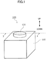
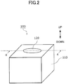
- FIG. 1 and FIG. 2 are perspective views illustrating different states of the electromechanical device 100 according to the embodiment, respectively.
- the electromechanical device 100 is a shift device installed in a vehicle, which is not depicted.
- An up and down direction in the embodiment is defined for convenience of the description, and the up and down direction does not limit an actual use direction.
- FIG. 3 is a schematic cross-sectional view of the electromechanical device 100 of FIG. 1 , in which an operation knob 120 is at a protruding position, that is obtained by cutting the electromechanical device 100 of FIG. 1 with a plane including a line 3-3 and a vertical direction that is a moving direction of the operation knob 120 and viewing it in the direction of the arrows.
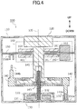
- FIG. 4 is a schematic cross-sectional view of the electromechanical device 100 of FIG. 2 , in which the operation knob 120 is at a retracted position, that is obtained by cutting the electromechanical device 100 of FIG. 2 by a plane including a line 4-4 and the vertical direction of the operation knob 120 and viewing it in the direction of the arrows.
- the electromechanical device 100 is provided with a case body 110 and the operation knob 120. Except for the operation knob 120, components of the electromechanical device 100 are accommodated inside the case body 110.
- the case body 110 may be omitted.
- the operation knob 120 Upon receiving user's rotational operation, the operation knob 120 switches a transmission.
- the operation knob 120 moves between the protruding position of FIG. 1 at which the operation knob 120 protrudes upward from the case body 110 and the retracted position illustrated in FIG. 2 at which the operation knob 120 is accommodated in the case body 110.
- the operation knob 120 moves from the retracted position of FIG. 2 to the protruding position of FIG. 1 , and, when the ignition switch is turned off, the operation knob 120 moves from the protruding position of FIG. 1 to the retracted position of FIG. 2 .
- the electromechanical device 100 is provided with a motor 130.
- the motor 130 according to the embodiment is a 4-pole/6-slot three-phase brushless motor; however, the motor 130 may be another brushless motor, or another motor, such as a stepping motor.
- the motor 130 includes a cover 131; a rotation shaft 132 protruding upward from inside the cover 131 to outside the cover 131; and a stator 133 disposed around the rotation shaft 132 in the cover 131. Grooves are formed on a cylindrical circumferential curved surface of the rotation shaft 132, so that it can function as a warm gear.
- FIG. 5 is a conceptual diagram illustrating an arrangement of a part of the components of the motor 130 when the part of the components of the motor 130 is viewed from above.
- the rotation shaft 132 rotates around a virtual center line 135 along the vertical direction.
- At a lower end of the rotation shaft 132 there are magnets in which four poles of NSNS are evenly arranged in a rotation direction, and the rotation shaft 132 functions as a rotor.
- Six coils (U1, V1, W1, U2, V2, and W2) are arranged around the rotor as a six-slot stator 133.
- the coil U1, coil V1, coil W1, coil U2, coil V2, and coil W2 are arranged counterclockwise around the center line 135 in this order at 60 degree intervals.
- the motor 130 is controlled by a method similar to a generic control method for a three-phase brushless motor.
- the rotation direction and the rotational speed are determined by a time-dependent variation of a control signal applied to the coils forming the stator 133.
- the motor 130 applies, to the rotation shaft 132, a torque toward an angular position in accordance with control by a controller 180, which is described below.
- a controller 180 which is described below.
- the stop target is determined. Namely, the motor 130 is controlled so that the motor 130 applies, to the rotation shaft 132, a torque toward the set stop target, in response to switching of signals from the outside.
- the same signals are applied to the coil U1 and the coil U2, the same signals are applied to the coil V1 and the coil V2, and the same signals are applied to the coil W1 and the coil W2.
- symmetrical signals are applied to the stator 133 every 180 degrees around the center line 135.
- the arrangement of the poles of the rotation shaft 132 is cyclic around the center line 135 with a period of 180 degrees. Accordingly, setting an angular position as a stop target implies setting another angular position that is obtained by rotating the position by 180 degrees around the center line 135 as a stop target.
- a torque toward the coil V1 is applied to the one of the S-poles. If the one of the S-poles is outside the range of ⁇ 90 degrees from the coil V1 as the center, the one of the S-pole receives a torque toward the coil V2.
- the rotation shaft 132 does not rotate beyond the range of ⁇ 90 degrees from the stop target, which is to be sequentially set.
- the motor 130 further includes three rotation sensors 134 that are disposed at 60 degree intervals around the center line 135.
- the rotation sensor 134 is a magnetic sensor, and, more specifically, the rotation sensor 134 is a Hall element utilizing Hall effect.
- the rotation sensors 134 detect an angular position of the rotation shaft 132.
- the rotation sensor 134 (HU) is disposed between the coil W2 and the coil U1.
- the rotation sensor 134 (HV) is disposed between the coil U1 and the coil V1.
- the rotation sensor 134 (HW) is disposed between the coil V1 and the coil W1.
- a rotation direction and an angular position of the rotation shaft 132 can be detected.
- the angular position corresponds to an angle of rotation of the rotation shaft 132.
- the rotation sensors 134 detects the angular position of the rotation shaft 132 on a basis of a unit of an angular range with a predetermined width.
- the angular range corresponding to one unit is referred to as a detection range.
- the electromechanical device 100 further includes an elevation shaft 141; a lifting stand 142; and a driven gear piece 143.
- the elevation shaft 141 is integrally coupled to the operation knob 120, and the elevation shaft 141 integrally rotates with the operation knob 120 around the center line 135.
- the lifting stand 142 rotatably holds the elevation shaft 141. While the lifting stand 142 is movable in the vertical direction, the lifting stand 142 is restricted by an element, which is not depicted, so that the lifting stand 142 is unable to rotate around the center line 135.
- the driven gear piece 143 is secured to the lifting stand 142, and the driven gear piece 143 is disposed around the rotation shaft 132. On a surface of the driven gear piece 143 facing the rotation shaft 132, gear grooves are formed that engages with the worm gear of the rotation shaft 132.
- the driven gear piece 143 When the rotation shaft 132 rotates, the driven gear piece 143 vertically moves without rotating. As the rotation shaft 132 rotates, the driven gear piece 143, the lifting stand 142, the elevation shaft 141, and the operation knob 120 integrally move in the vertical direction. While the driven gear piece 143 and the lifting stand 142 are unable to rotate around the center line 135, the operation knob 120 and the elevation shaft 141 can rotate around the center line 135 in both directions. The operation knob 120 and the elevation shaft 141 can be rotated independently of the rotation of the rotation shaft 132. As the rotation shaft 132 rotates, the worm gear of the rotation shaft 132 and the driven gear piece 143 function as a moving mechanism for moving the operation knob 120 along a predetermined path.
- the predetermined path is a straight line that is parallel with the center line 135.
- the lifting stand 142 is provided with two light shielding pieces, which are a lower light shielding piece 144a and an upper light shielding piece 144b described below (hereinafter, they may be referred to as light shielding pieces 144 without distinction).
- the lower light shielding piece 144a protrudes downward from a part of the lifting stand 142
- the upper light shielding piece 144b protrudes upward from a part of the lifting stand 142.
- a movement amount of the light shielding piece 144 in the vertical direction is equal to a movement amount of the operation knob 120.
- the electromechanical device 100 further includes a circuit board 150.
- the circuit board 150 is disposed to partition the space inside the case body 110 in the vertical direction.
- the circuit board 150 is disposed between the operation knob 120 and the lifting stand 142, and the circuit board 150 is disposed so that the elevation shaft 141 passes through the circuit board 150 without touching it.
- the electromechanical device 100 further includes a lower position sensor 151a and an upper position sensor 151b (which may be referred to as the position sensors 151 without distinction, hereinafter).
- the position sensor 151 is a photo sensor for indirectly detecting a position of the operation knob 120 by detecting the position of the light shielding piece 144.
- the lower position sensor 151a is disposed on a bottom surface inside the case body 110, and the lower position sensor 151a detects a position of the lower light shielding piece 144a.
- the upper position sensor 151b is disposed on a lower surface of the circuit board 150, and the upper position sensor 151b detects a position of the upper light shielding piece 144b.
- the position sensor 151 defines an internal space having an opening at one of an upper side and a lower side.
- the position sensor 151 detects whether an object exists in the internal space by light.
- the position sensor 151 is turned on, and when the light shielding piece 144 does not exist inside the internal space, the position sensor 151 is turned off.
- a moving amount of the light shielding piece 144 is equal to a moving amount of the operation knob 120.
- the position sensor 151 indirectly detects a position of the operation knob 120 through the light shielding piece 144.
- the operation knob 120 moves in the vertical direction between the retracted position at which the light shielding piece 144 causes the lower position sensor 151a to turn on and the protruding position at which the light shielding piece 144 causes the upper position sensor 151b to turn on.
- the electromechanical device 100 further includes an operation detection unit 160 mounted on the circuit board 150.
- the operation detection unit 160 includes two rotating disks 161 disposed on both sides of the circuit board 150 and an operation amount sensor 162 of the rotating disks 161.
- the elevation shaft 141 is disposed so that the elevation shaft 141 passes through the rotating disks 161.
- On a cylindrical side surface of the elevation shaft 141 a groove is formed that extends in the vertical direction, and an engaging piece of the rotating disks 161 engages with the groove of the elevation shaft 141. While the rotating disks 161 are rotatable around the center line 135 by components, which are not depicted, the rotating disks 161 are restricted by the circuit board 150 so that the rotating disks 161 do not move in the vertical direction.
- the elevation shaft 141 moves in the vertical direction, an engaging piece of the rotating disks 161 slides in the groove of the elevation shaft 141, and, thus, the rotating disks 161 do not move in the vertical direction.
- the elevation shaft 141 rotates around the center line 135, the engaging piece of the rotating disks 161 is pressed by the groove of the elevation shaft 141, and the rotating disks 161 rotate together with the elevation shaft 141.
- a rotation amount of the rotating disks 161 is detected by the operation amount sensor 162 that is formed of a magnetic sensor. Namely, the rotation operation of the operation knob 120 is detected by the operation amount sensor 162 through the elevation shaft 141 and the rotating disks 161. Note that the detection method of the rotation operation of the operation knob 120 is not limited to this.
- FIG. 6 is a configuration diagram of a control system related to controlling the movement of the electromechanical device 100 in the vertical direction.
- the electromechanical device 100 is provided with a motor drive circuit 170, a controller 180, and a storage 190 depicted in FIG. 6 , which are installed on the circuit board 150 illustrated in FIG. 3 .
- the motor drive circuit 170 controls the motor 130 based on an indication from the controller 180 to rotate the rotation shaft 132 ( FIG. 3 ) in a desired direction at desired speed, and to stop the rotation shaft 132 ( FIG. 3 ).
- the controller 180 is a central processing unit.
- the storage 190 is, for example, a random access memory (RAM; random access memory).
- the storage 190 may be another device that can store information.
- the controller 180 executes various controls of the electromechanical device 100 by reading and executing a program stored in the storage 190.
- the controller 180 may be formed of another component, and the controller 180 may be an application specific integrated circuit (ASIC; application specific integrated circuit).
- ASIC application specific integrated circuit
- the controller 180 is connected to the motor drive circuit 170, the lower position sensor 151a, the upper position sensor 151b, the rotation sensor 134 (HU), the rotation sensor (HV), and the rotation sensor 134 (HW).
- the controller 180 functions as a motor controller by reading and executing a program stored in the storage 190. Additionally, the controller 180 generates drive waveforms and performs three-phase drive control on the motor drive circuit 170. Additionally, the controller 180 executes a process for calculating a rotational position, rotational speed, and rotational acceleration of the rotation shaft 132 based on a detection result from the rotation sensors 134, and the controller 180 generates drive waveforms based on these results.
- the controller 180 applies a torque to the rotation shaft 132 so that the rotational speed becomes target rotational speed toward an angular position that is a stop target, based on the angular position of the rotation shaft 132 detected by the rotation sensors 134.
- FIG. 7 is a diagram illustrating a relative pattern 31 and an absolute pattern 33 used for rotation control of the rotation shaft 132 by the controller 180 illustrated in FIG. 6 .
- the horizontal axis represents a rotational (angle) position of the rotation shaft 132 in terms of a count of the rotation sensors 134
- the vertical axis represents rotational speed (deg/s).
- "0" is a count at a time at which the operation knob 120 is at the lowermost end (the retracted position illustrated in FIG. 2 : the normal rotation start position).
- each of the relative pattern 31 and the absolute pattern 33 defines the relation between the angular position and the target rotational speed of the rotation shaft 132.
- the target rotational speed defined by the relative pattern 31 is referred to as relative target rotational speed
- the target rotational speed defined by the absolute pattern 33 is referred to as the absolute target rotational speed.
- an angular position (rotational position) between a normal rotation start position 33a that is an angular position of the rotation shaft 132 at a time at which the operation knob 120 is at the retracted position illustrated in FIG. 2 and an angular position of the rotation shaft 132 at a time at which the operation knob 120 is at the protruding position illustrated in FIG. 1 is referred to as a middle start position 31a. If the operation knob 120 stops due to a factor, such as external force, during a process of moving from the retracted position illustrated in FIG. 2 to the protruding position illustrated in FIG. 1 , and if the operation knob 120 starts moving again, the movement start position is referred to as the middle start position.
- the relative pattern 31 defines the relation between the angular position and the relative target rotational speed of the rotation shaft 132 using the middle start position 31a as a reference.
- the absolute pattern 33 defines, in advance, the relation between the angular position and the absolute target rotational speed of the rotation shaft 132 using the normal rotation start position 33a as a reference.
- the relative pattern 31 and the absolute pattern 33 are patterns having the same shapes.
- the controller 180 creates the relative pattern 31 based on the absolute pattern 33. For example, the controller 180 reads out pattern data of the absolute pattern 33 stored in the storage 190, and the controller 180 creates the relative pattern 31 by processing the absolute pattern 33 so that the middle start position 31a becomes the start position. The data amount can be reduced, as it is unnecessary to maintain patterns from all the middle start positions 31a.
- maximum target rotational speed wmax and acceleration from initial rotational speed wmin until the maximum target rotational speed wmax is reached are the same.
- the middle start position 31a that is an increment start angular position of the relative target rotational speed in the relative pattern 31 is greater than the normal rotation start position 33a that is an increment start angular position of the absolute target rotational speed in the absolute pattern.
- a decrement start angular position 31b from the maximum target rotational speed wmax of the relative target rotational speed in the relative pattern 31 is greater than a decrement start angular position 33b from the maximum target rotational speed of the absolute target rotational speed in the absolute pattern 33.
- the shapes of the relative pattern 31 and the absolute pattern 33 are the same, and the increment start angular positions are shifted.
- the relative pattern 31 and the absolute pattern 33 are defined so that all the required specifications on a target position arrival time from the normal rotation start position 33a to a normal rotation end position of the operation knob 120, noise, a stopping precision, and a drive electric current can be satisfied.
- Each of the relative pattern 31 and the absolute pattern 33 may be implemented, for example, as table data stored in the storage 190, or may be implemented as a function for outputting the target rotational speed using the rotational position as a variable.
- the controller 180 When the rotation shaft 132 starts rotation from the normal rotation start position 33a, namely, when the operation knob 120 moves upward from the retracted position illustrated in FIG. 2 , the controller 180 operates in an absolute mode such that the controller 180 identifies the absolute rotational speed corresponding to the angular position detected by the rotation sensors 134 using the absolute pattern 33 illustrated in FIG. 7 , and the controller 180 controls the rotation of the rotation shaft 132 so that the identified absolute rotational speed is achieved.
- the controller 180 When the rotation shaft 132 start rotation from the middle start position 31a, namely, when the operation knob 120 moves upward from a position between the retracted position illustrated in FIG. 2 and the protruding position illustrated in FIG. 1 , the controller 180 operates in a relative mode such that the controller 180 identifies the relative target rotational speed corresponding to the angular position detected by the rotation sensors 134 using the relative pattern 31 illustrated in FIG. 7 , and the controller 180 controls the rotation of the rotation shaft 132 so that the identified relative rotational speed is achieved.
- the controller 180 identifies the absolute rotational speed corresponding to the angular position detected by the rotation sensors 134 using the absolute pattern 33. Then, if a condition is not satisfied such that the identified absolute rotational speed is greater than the relative target rotational speed identified corresponding to the detected angular position, the controller 180 switches the rotation control mode from the relative mode to the absolute mode. As a result, as illustrated in FIG. 8 , the rotational speed corresponding to the angular position detected by the rotation sensors 134 can be identified using a new dynamic pattern 35, and the rotation of the rotation shaft 132 can be properly controlled so that the identified rotational speed is achieved.
- FIG. 9 is a flowchart illustrating the rotation control method of the rotation shaft 132 by the controller 180 depicted in FIG. 6 .
- the controller 180 determines whether the lifting operation of the operation knob 120 is from the middle start position, based on a detection result of the position sensor 151. The controller 180 moves to step ST2, if the determination is positive, and the controller 180 moves to step ST3, if the determination is negative.
- the controller 180 sets the rotation control mode to the relative mode. At this time, for example, the counter value of the rotation sensors 134 at the time at which the lifting operation of the operation knob 120 is stopped last time is used as the middle start position 31a.
- the controller 180 sets the rotation control mode to the absolute mode. At this time, the count value "0" of the rotation sensors 134 at the retracted position illustrated in FIG. 2 is the normal rotation start position 33a.
- the controller 180 identifies, using the relative pattern 31, the relative target rotational speed corresponding to the angular position detected by the rotation sensors 134. Additionally, the controller 180 identifies, using the absolute pattern 33, the absolute target rotational speed corresponding to the angular position detected by the rotation sensors 134.
- step ST6 If the rotation control mode is the relative mode, the controller 180 moves to step ST6, and if the rotation control mode is the absolute mode, the controller 180 moves to step ST9.
- the controller 180 determines whether the absolute rotational speed is greater than the relative target rotational speed identified at step ST4. If the determination is positive, the controller 180 moves to step ST7, and if the determination is negative, the controller 180 moves to step ST8.
- the controller 180 controls the rotation of the rotation shaft 132 using the relative target rotational speed identified at step ST4 as the target speed.
- the controller 180 switches the rotation control mode from the relative mode to the absolute mode.
- the controller 180 controls the rotation of the rotation shaft 132 using the absolute target rotational speed identified at step ST4 as the target speed.
- the controller 180 waits for a predetermined processing cycle after completing the process of step ST7 or step ST9, and, then, returns to the process of step ST4.
- the electromechanical device 100 defines the target rotational speed (the relative target rotational speed) using the relative pattern 31 for which the middle start position 31a is used as the reference, instead of using the absolute pattern 33 that is defined using the normal rotation start position 33a as the reference.
- the relative target rotational speed which is low speed
- the relative target rotational speed which is low speed
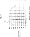
- the absolute target rotational speed which is high speed, defined by the absolute pattern 33, as illustrated in FIG. 10 .
- required specification for the drive circuit can be lowered.
- a gear, etc. is connected to the rotation shaft 132, it can be suppressed that a large torque is rapidly generated and the gear starts rotating at high speed, so that collision sound can be suppressed.
- the absolute pattern 33 is used at the middle start position 31a
- the acceleration curve characteristic is insufficient at the time of restarting the rotation, and the initial target rotation speed becomes large. According to the electromechanical device 100, such a problem can be resolved.
- the motor control is switched so that the absolute pattern 33 is used. Accordingly, after the relative target rotational speed reaches the absolute target rotational speed, the target rotational speed can be made equal to that of a case in which the rotation of the rotation shaft 132 does not stop in the middle. As a result, the target rotational speed in the vicinity of the position at which the rotation is stopped can be made constant.
- the controller 180 controls the motor 130 using the absolute pattern 33 so that the absolute target rotational speed corresponding to the detected angular position can be achieved.
- the motor 130 can be controlled using the absolute pattern 33, without using the relative pattern 31.
- the maximum target rotational speed and the acceleration until the maximum target rotational speed is reached are the same for the relative pattern 31 and the absolute pattern 33, which are depicted in FIG. 7 .
- the change in the target rotational speed can be smoothed.
- the increment start angular position of the relative target rotational speed in the relative pattern 31 (the middle start position 31a) is greater than the increment start angular position of the absolute target rotational speed in the absolute pattern 33 (the normal rotation start position 33a), and the decrement start angular position 31b from the maximum target rotational speed of the relative target rotational speed in the relative pattern 31 is greater than the decrement start angular position 33b from the maximum target rotational speed of the absolute target rotational speed in the absolute pattern 33.
- the relative target rotational speed that is lower than the absolute target rotational speed defined by the absolute pattern 33 can be used at the middle start position 31a, and thereby a large electric current can be prevented from flowing and the speed tracking error can be reduced.
- the relative pattern 31 is created using the absolute pattern 33. Further, in the electromechanical device 100, the relative pattern 31 and the absolute pattern 33 have the same shapes. As a result, it is unnecessary to prepare relative patterns 31 for all the middle start positions 31a, and it can be implemented by a simple and inexpensive configuration. Further, if the rotation is restarted from the middle start position 31a, a rotational acceleration pattern can be achieved that is the same as that of a case in which the rotation is started from the normal rotation start position 33a.
- the present invention is not limited to the above-described embodiment. Namely, a person ordinarily skilled in the art may make various modifications, combinations, sub-combinations, and substitutions for the components of the above-described embodiment within the technical scope of the present invention or the equivalent thereof.
- a case is exemplified in which the operation knob 120 moves from the retracted position illustrated in FIG. 2 to the protruding position illustrated in FIG. 1 ; however, it can be similarly applied to a case in which the operation knob 120 moves from the protruding position illustrated in FIG. 1 to the retracted position illustrated in FIG. 2 .
- the protruding position illustrated in FIG. 1 is the normal rotation start position 33a.
- the present invention can be applied to various electromechanical devices in which various components are moved by rotation of rotation shafts of motors.
- it can be applied to shift devices that are installed in various vehicles, such as an automobile, an aircraft, and a ship.
Landscapes
- Engineering & Computer Science (AREA)
- Power Engineering (AREA)
- General Physics & Mathematics (AREA)
- Automation & Control Theory (AREA)
- Physics & Mathematics (AREA)
- Transportation (AREA)
- Chemical & Material Sciences (AREA)
- Combustion & Propulsion (AREA)
- Mechanical Engineering (AREA)
- Manufacturing & Machinery (AREA)
- Human Computer Interaction (AREA)
- Control Of Motors That Do Not Use Commutators (AREA)
- Mechanical Control Devices (AREA)
- Control Of Position Or Direction (AREA)
Abstract
Description
- The present invention relates to an electromechanical device, a motor controller, and a rotation control method.
- An electromechanical device in which a motor is installed causes various components to operate by rotation of a rotation shaft of the motor. For example, a shift device installed in a vehicle, which is a type of an electromechanical device, switches a transmission in response to an operation of an operation knob. Such an electromechanical device includes a device such that, upon an ignition switch being turned on, an operation knob that is stored on a surface that is approximately the same as a surface of an operations panel protrudes from the operations panel. The movement of the operation knob is achieved by converting rotation of a motor into a translational movement. It is required to move the operation knob to a home position within a predetermined time, as the operation knob is indispensable for driving the vehicle.
- According to
Patent Document 1, at a start of operation, a soft start is performed by increasing a drive duty ratio at a fixed rate, and, upon detecting that soft start termination determination speed is reached that is set to be lower than target speed, the operation transitions to constant speed control. It is disclosed that, for this speed control, when a motor is accelerated, an actual drive current control output value and a drive electric current at that time are detected by using a control pattern in which relation between a drive control output value and a drive electric current of a motor is mapped, and the speed is controlled by comparing an output value of the drive electric current based on the mapping with a determination value. - Additionally,
Patent Document 2 discloses a motor control method such that the motor moves at a constant high speed during movement, and the motor quickly and gently stops when it is to be stopped. -
- [Patent Document 1] Japanese Unexamined Patent Publication No.
2002-345294 - [Patent Document 1] Japanese Unexamined Patent Publication No.
2007-209179 - In the above-described related art, when the operation is started from an upper end or a lower end of a movement range of the operation knob, there is no problem for controlling the speed using the above-described mapped pattern, etc. However, during movement, when the operation knob is caused to stop by a factor, such as an application of external force, and then the movement is restarted, movement is started at a speed that is higher than the speed at a normal start of the movement at a movement restart position, if the target speed is used as it is, which corresponds to the normal movement start position that is defined by the above-described pattern. Furthermore, an acceleration curve characteristic required for starting the movement is not obtained at the movement start position.
- As a result, a speed tracking error at the restart of the movement of the operation knob increases and a large electric current flows, and a problem is that high performance is required for a drive circuit. Further, large torque is applied at the restart of the operation knob, and a problem is that a collision noise of components, such as gears inside the electromechanical device, is generated. In an environment in which a person is located in the vicinity, or in a quiet environment that is closed, small collision sound may be perceived as noise. Accordingly, there is a need for suppressing sound at a restart of an electromechanical device, even if a volume of the sound is small.
- The present invention is achieved in view of such a circumstance, and an object is to provide an electromechanical device, a motor controller, and a rotation control method that can execute rotation control using appropriate target rotational speed, even if the rotation is to be restarted at a middle start position.
- In order to solve the above-described problem, an electromechanical device according to the present invention includes a motor that includes a rotation shaft and that applies, to the rotation shaft, a torque toward an angular position in accordance with control; a rotation sensor that detects the angular position of the rotation shaft; and a motor controller that controls rotational speed of the rotation shaft depending on the angular position detected by the rotation sensor, wherein the motor controller determines, based on a detection result by the rotation sensor, whether a rotation start position of the rotation shaft is a predetermined normal rotation start position, wherein, upon determining that the rotation start position is a middle start position other than the normal rotation start position, the motor controller controls the motor using a relative pattern that defines, using the middle start position as a reference, relation between the angular position and relative target rotational speed, so that the relative target rotational speed corresponding to the detected angular position is achieved, and wherein the motor controller uses an absolute pattern that defines, using the normal rotation start position as a reference, relation between the angular position and an absolute target rotational speed to identify the absolute target rotational speed corresponding to the detected angular position, wherein, upon detecting that a condition that the identified absolute target rotational speed is greater than the relative target rotational speed corresponding to the detected angular position is not satisfied, the motor controller controls the motor using the absolute pattern, so that the absolute target rotational speed corresponding to the angular position is achieved.
- According to this configuration, when the rotation start position of the rotation shaft is the middle start position (namely, when the rotation of the rotation shaft is stopped in the middle and it is restarted), the target rotational speed (the relative target rotational speed) is defined using the relative pattern with the middle start position as the reference, without using the absolute pattern defined with the normal rotation start position as the reference. Accordingly, by defining an appropriate pattern as the relative pattern, the absolute target rotational speed that is high speed defined by the absolute pattern is not used at the middle start position, so that it can be prevented that a large electric current flows, and that the speed tracking error can be reduced, using the relative target rotational speed that is low speed. Furthermore, it is possible to lower the level of the specification required for the drive circuit. Furthermore, if a gear is connected to the rotation shaft, it can be suppressed that a large torque is rapidly generated and the gear starts rotating at high speed, so that collision sound can be suppressed. Namely, if the absolute pattern is used at the middle start position, an acceleration curve characteristic at the start is insufficient and the initial target rotational speed becomes large. According to the present invention, such a problem can be solved.
- Further, according to this configuration, while performing rotation control using the relative pattern, upon detecting that the condition that the absolute target rotational speed corresponding to the detected angular position is greater than the relative target rotational speed is not satisfied, the motor control is switched, so that the absolute pattern is used. Accordingly, after the relative target rotational speed reaches the absolute target rotational speed, the target rotational speed can be made identical to that of a case in which the rotation of the rotation shaft does not stop in the middle. As a result, the target rotational speed in the vicinity of the position at which the rotation is stopped can be made constant.
- Preferably, upon determining that the rotation start position of the rotation shaft is the normal rotation start position based on the detection result by the rotation sensor, the motor controller of the electromechanical device according to the present invention controls the motor using the absolute pattern, so that the absolute target rotational speed corresponding to the detected angular position is achieved.
- According to this configuration, when the rotation start position of the rotation shaft is the normal rotation start position, the motor can be controlled using the absolute pattern, without using the relative pattern.
- Preferably, in the electromechanical device according to the present invention, a maximum target rotational speed and acceleration until the maximum target rotational speed is achieved are identical for the relative pattern and for the absolute pattern. According to this configuration, even if the relative pattern and the absolute pattern are switched, the change in the target rotational speed can be smoothed.
- Preferably, in the electromechanical device according to the present invention, an increment start angular position of the relative target rotational speed in the relative pattern is greater than an increment start angular position of the absolute target rotational speed in the absolute pattern, and a decrement start angular position from the maximum target rotational speed of the relative target rotational speed in the relative pattern is greater than a decrement start angular position from the maximum target rotational speed of the absolute target rotational speed in the absolute pattern. According to this configuration, the relative target rotational speed that is lower than the absolute target rotational speed defined by the absolute pattern can be used at the middle start position, and a large electric current can be prevented from flowing and the speed tracking error can be reduced.
- Preferably, in the electromechanical device according to the present invention, the relative pattern is created using the absolute pattern. According to this configuration, the relative pattern can be created using the absolute pattern, and it can be implemented by a simple and inexpensive configuration.
- Preferably, in the electromechanical device according to the present invention, the relative pattern and the absolute pattern have identical shapes. According to this configuration, the relative pattern can be created using the absolute pattern, and it can be implemented by a simple and inexpensive configuration.
- Preferably, the electromechanical device according to the present invention, further includes an operation knob; and a moving system that moves the operation knob along a predetermined path as the rotation shaft rotates, and a transmission is switched by the operation knob. According to this configuration, when the operation knob stops in the middle of movement by the moving system due to application of external force, and the movement is restarted, a large electric current can be prevented from flowing. Additionally, it can be suppressed that rapid rotation, etc., is generated and collision sound is generated in the moving system.
- Preferably, the relative pattern and the absolute pattern of the electromechanical device according to the present invention are defined so that all required specifications on a target position arrival time from the normal rotation start position to a normal rotation end position of the operation knob, noise, a stopping precision, and a drive electric current are satisfied.
- A motor controller according to the present invention is a motor controller for controlling a motor that includes a rotation shaft and that applies, to the rotation shaft, a torque toward an angular position in accordance with control, the motor controller including a rotation sensor that detects the angular position of the rotation shaft; and a motor controller that controls rotational speed of the rotation shaft depending on the angular position detected by the rotation sensor, wherein the motor controller determines, based on a detection result by the rotation sensor, whether a rotation start position of the rotation shaft is a predetermined normal rotation start position, wherein, upon determining that the rotation start position is a middle start position other than the normal rotation start position, the motor controller controls the motor using a relative pattern that defines, using the middle start position as a reference, relation between the angular position and relative target rotational speed, so that the relative target rotational speed corresponding to the detected angular position is achieved, and wherein the motor controller uses an absolute pattern that defines, using the normal rotation start position as a reference, relation between the angular position and an absolute target rotational speed to identify the absolute target rotational speed corresponding to the detected angular position, wherein, upon detecting that a condition that the identified absolute target rotational speed is greater than the relative target rotational speed corresponding to the detected angular position is not satisfied, the motor controller controls the motor using the absolute pattern, so that the absolute target rotational speed corresponding to the detected angular position is achieved.
- A motor control method according to the present invention is a motor control method for controlling rotational speed of a motor that includes a rotation shaft and that applies, to the rotation shaft, a torque toward an angular position in accordance with control, the motor control method including: determining, based on a detection result by a rotation sensor that detects the angular position of the rotation shaft, whether a rotation start position of the rotation shaft is a predetermined normal rotation start position, wherein, upon determining that the rotation start position is a middle start position other than the normal rotation start position, controlling the motor using a relative pattern that defines, using the middle start position as a reference, relation between the angular position and relative target rotational speed, so that the relative target rotational speed corresponding to the detected angular position is achieved; identifying the absolute target rotational speed corresponding to the detected angular position, using an absolute pattern that defines, using the normal rotation start position as a reference, relation between the angular position and an absolute target rotational speed; and upon detecting that a condition that the identified absolute target rotational speed is greater than the relative target rotational speed corresponding to the detected angular position is not satisfied, controlling the motor using the absolute pattern, so that the absolute target rotational speed corresponding to the detected angular position is achieved.
- According to the present invention, there can be provided an electromechanical device, a motor controller, and a rotation control method that can execute rotation control using an appropriate target rotational speed, even if the rotation is to be restarted at a middle start position.
-
-
FIG. 1 is a perspective view of an electromechanical device according to an embodiment of the present invention. -
FIG. 2 is another perspective view of the electromechanical device ofFIG. 1 . -
FIG. 3 is a cross-sectional view along a line 3-3 of the electromechanical device ofFIG. 1 . -
FIG. 4 is a cross-sectional view along a line 4-4 of the electromechanical device ofFIG. 2 . -
FIG. 5 is a conceptual diagram illustrating an arrangement of a part of components of a motor. -
FIG. 6 is a configuration diagram of a control system of the electromechanical device ofFIG. 1 . -
FIG. 7 is a diagram illustrating a relative pattern and an absolute pattern that are used for rotation control of a rotation shaft by a controller, which is depicted inFIG. 6 . -
FIG. 8 is a diagram illustrating a pattern for speed control, which is newly created by switching operation of the controller depicted inFIG. 6 . -
FIG. 9 is a flowchart illustrating a rotation control method of a rotation shaft by the controller depicted inFIG. 6 . -
FIG. 10 is a diagram illustrating a target rotational speed control in an electromechanical device according to related art. - An
electromechanical device 100 according to an embodiment is an electronic shifter provided with functions for raising, lowering, and rotating an operation knob. Speed curve control of a motor for the raising and lowering drive is executed in a condition in which parameters are optimized, and, in the speed curve control, even if raising and lowering of the operation knob is restarted at any position, no large torque is rapidly generated, and the operation knob can be accurately positioned at a predetermined position. - In the following, an electromechanical device according to the embodiment of the present invention is described.
FIG. 1 andFIG. 2 are perspective views illustrating different states of theelectromechanical device 100 according to the embodiment, respectively. Theelectromechanical device 100 is a shift device installed in a vehicle, which is not depicted. An up and down direction in the embodiment is defined for convenience of the description, and the up and down direction does not limit an actual use direction. -
FIG. 3 is a schematic cross-sectional view of theelectromechanical device 100 ofFIG. 1 , in which anoperation knob 120 is at a protruding position, that is obtained by cutting theelectromechanical device 100 ofFIG. 1 with a plane including a line 3-3 and a vertical direction that is a moving direction of theoperation knob 120 and viewing it in the direction of the arrows.FIG. 4 is a schematic cross-sectional view of theelectromechanical device 100 ofFIG. 2 , in which theoperation knob 120 is at a retracted position, that is obtained by cutting theelectromechanical device 100 ofFIG. 2 by a plane including a line 4-4 and the vertical direction of theoperation knob 120 and viewing it in the direction of the arrows. - As illustrated in
FIG. 1 , theelectromechanical device 100 is provided with acase body 110 and theoperation knob 120. Except for theoperation knob 120, components of theelectromechanical device 100 are accommodated inside thecase body 110. Thecase body 110 may be omitted. - Upon receiving user's rotational operation, the
operation knob 120 switches a transmission. Theoperation knob 120 moves between the protruding position ofFIG. 1 at which theoperation knob 120 protrudes upward from thecase body 110 and the retracted position illustrated inFIG. 2 at which theoperation knob 120 is accommodated in thecase body 110. For example, when an ignition switch, which is not depicted, of a vehicle is turned on, theoperation knob 120 moves from the retracted position ofFIG. 2 to the protruding position ofFIG. 1 , and, when the ignition switch is turned off, theoperation knob 120 moves from the protruding position ofFIG. 1 to the retracted position ofFIG. 2 . - As illustrated in
FIG. 3 , theelectromechanical device 100 is provided with amotor 130. Themotor 130 according to the embodiment is a 4-pole/6-slot three-phase brushless motor; however, themotor 130 may be another brushless motor, or another motor, such as a stepping motor. Themotor 130 includes acover 131; arotation shaft 132 protruding upward from inside thecover 131 to outside thecover 131; and astator 133 disposed around therotation shaft 132 in thecover 131. Grooves are formed on a cylindrical circumferential curved surface of therotation shaft 132, so that it can function as a warm gear. -
FIG. 5 is a conceptual diagram illustrating an arrangement of a part of the components of themotor 130 when the part of the components of themotor 130 is viewed from above. Therotation shaft 132 rotates around avirtual center line 135 along the vertical direction. At a lower end of therotation shaft 132, there are magnets in which four poles of NSNS are evenly arranged in a rotation direction, and therotation shaft 132 functions as a rotor. Six coils (U1, V1, W1, U2, V2, and W2) are arranged around the rotor as a six-slot stator 133. The coil U1, coil V1, coil W1, coil U2, coil V2, and coil W2 are arranged counterclockwise around thecenter line 135 in this order at 60 degree intervals. - The
motor 130 is controlled by a method similar to a generic control method for a three-phase brushless motor. The rotation direction and the rotational speed are determined by a time-dependent variation of a control signal applied to the coils forming thestator 133. - The
motor 130 applies, to therotation shaft 132, a torque toward an angular position in accordance with control by acontroller 180, which is described below. During stop control, one of twelve angular positions, which are arranged at respective angular ranges obtained by dividing one rotation of therotation shaft 132 into twelve equal parts, is set to be a stop target. Depending on a difference of a signal to be applied to thestator 133, the stop target is determined. Namely, themotor 130 is controlled so that themotor 130 applies, to therotation shaft 132, a torque toward the set stop target, in response to switching of signals from the outside. - Note that, the same signals are applied to the coil U1 and the coil U2, the same signals are applied to the coil V1 and the coil V2, and the same signals are applied to the coil W1 and the coil W2. Namely, symmetrical signals are applied to the
stator 133 every 180 degrees around thecenter line 135. Additionally, the arrangement of the poles of therotation shaft 132 is cyclic around thecenter line 135 with a period of 180 degrees. Accordingly, setting an angular position as a stop target implies setting another angular position that is obtained by rotating the position by 180 degrees around thecenter line 135 as a stop target. For example, if one of the S-poles is within a range of ± 90 degrees from the coil V1 as the center, a torque toward the coil V1 is applied to the one of the S-poles. If the one of the S-poles is outside the range of ± 90 degrees from the coil V1 as the center, the one of the S-pole receives a torque toward the coil V2. In this specification, a case is described in which therotation shaft 132 does not rotate beyond the range of ± 90 degrees from the stop target, which is to be sequentially set. - The
motor 130 further includes threerotation sensors 134 that are disposed at 60 degree intervals around thecenter line 135. Therotation sensor 134 is a magnetic sensor, and, more specifically, therotation sensor 134 is a Hall element utilizing Hall effect. Therotation sensors 134 detect an angular position of therotation shaft 132. The rotation sensor 134 (HU) is disposed between the coil W2 and the coil U1. The rotation sensor 134 (HV) is disposed between the coil U1 and the coil V1. The rotation sensor 134 (HW) is disposed between the coil V1 and the coil W1. - Based on a pattern of signals output from the three
rotation sensors 134, a rotation direction and an angular position of therotation shaft 132 can be detected. The angular position corresponds to an angle of rotation of therotation shaft 132. Therotation sensors 134 detects the angular position of therotation shaft 132 on a basis of a unit of an angular range with a predetermined width. The angular range corresponding to one unit is referred to as a detection range. - As illustrated in
FIG. 3 , theelectromechanical device 100 further includes anelevation shaft 141; alifting stand 142; and a drivengear piece 143. Theelevation shaft 141 is integrally coupled to theoperation knob 120, and theelevation shaft 141 integrally rotates with theoperation knob 120 around thecenter line 135. The lifting stand 142 rotatably holds theelevation shaft 141. While the liftingstand 142 is movable in the vertical direction, the liftingstand 142 is restricted by an element, which is not depicted, so that the liftingstand 142 is unable to rotate around thecenter line 135. The drivengear piece 143 is secured to thelifting stand 142, and the drivengear piece 143 is disposed around therotation shaft 132. On a surface of the drivengear piece 143 facing therotation shaft 132, gear grooves are formed that engages with the worm gear of therotation shaft 132. - When the
rotation shaft 132 rotates, the drivengear piece 143 vertically moves without rotating. As therotation shaft 132 rotates, the drivengear piece 143, the liftingstand 142, theelevation shaft 141, and theoperation knob 120 integrally move in the vertical direction. While the drivengear piece 143 and thelifting stand 142 are unable to rotate around thecenter line 135, theoperation knob 120 and theelevation shaft 141 can rotate around thecenter line 135 in both directions. Theoperation knob 120 and theelevation shaft 141 can be rotated independently of the rotation of therotation shaft 132. As therotation shaft 132 rotates, the worm gear of therotation shaft 132 and the drivengear piece 143 function as a moving mechanism for moving theoperation knob 120 along a predetermined path. The predetermined path is a straight line that is parallel with thecenter line 135. - The lifting stand 142 is provided with two light shielding pieces, which are a lower
light shielding piece 144a and an upperlight shielding piece 144b described below (hereinafter, they may be referred to as light shielding pieces 144 without distinction). The lowerlight shielding piece 144a protrudes downward from a part of the liftingstand 142, and the upperlight shielding piece 144b protrudes upward from a part of the liftingstand 142. A movement amount of the light shielding piece 144 in the vertical direction is equal to a movement amount of theoperation knob 120. - The
electromechanical device 100 further includes acircuit board 150. Thecircuit board 150 is disposed to partition the space inside thecase body 110 in the vertical direction. Thecircuit board 150 is disposed between theoperation knob 120 and thelifting stand 142, and thecircuit board 150 is disposed so that theelevation shaft 141 passes through thecircuit board 150 without touching it. - The
electromechanical device 100 further includes alower position sensor 151a and anupper position sensor 151b (which may be referred to as the position sensors 151 without distinction, hereinafter). The position sensor 151 is a photo sensor for indirectly detecting a position of theoperation knob 120 by detecting the position of the light shielding piece 144. Thelower position sensor 151a is disposed on a bottom surface inside thecase body 110, and thelower position sensor 151a detects a position of the lowerlight shielding piece 144a. Theupper position sensor 151b is disposed on a lower surface of thecircuit board 150, and theupper position sensor 151b detects a position of the upperlight shielding piece 144b. - The position sensor 151 defines an internal space having an opening at one of an upper side and a lower side. The position sensor 151 detects whether an object exists in the internal space by light. When the light shielding piece 144 exists inside the internal space, the position sensor 151 is turned on, and when the light shielding piece 144 does not exist inside the internal space, the position sensor 151 is turned off. In the vertical direction, a moving amount of the light shielding piece 144 is equal to a moving amount of the
operation knob 120. The position sensor 151 indirectly detects a position of theoperation knob 120 through the light shielding piece 144. Theoperation knob 120 moves in the vertical direction between the retracted position at which the light shielding piece 144 causes thelower position sensor 151a to turn on and the protruding position at which the light shielding piece 144 causes theupper position sensor 151b to turn on. - The
electromechanical device 100 further includes anoperation detection unit 160 mounted on thecircuit board 150. Theoperation detection unit 160 includes tworotating disks 161 disposed on both sides of thecircuit board 150 and anoperation amount sensor 162 of therotating disks 161. Theelevation shaft 141 is disposed so that theelevation shaft 141 passes through therotating disks 161. On a cylindrical side surface of theelevation shaft 141, a groove is formed that extends in the vertical direction, and an engaging piece of therotating disks 161 engages with the groove of theelevation shaft 141. While therotating disks 161 are rotatable around thecenter line 135 by components, which are not depicted, the rotatingdisks 161 are restricted by thecircuit board 150 so that therotating disks 161 do not move in the vertical direction. - When the
elevation shaft 141 moves in the vertical direction, an engaging piece of therotating disks 161 slides in the groove of theelevation shaft 141, and, thus, the rotatingdisks 161 do not move in the vertical direction. When theelevation shaft 141 rotates around thecenter line 135, the engaging piece of therotating disks 161 is pressed by the groove of theelevation shaft 141, and therotating disks 161 rotate together with theelevation shaft 141. A rotation amount of therotating disks 161 is detected by theoperation amount sensor 162 that is formed of a magnetic sensor. Namely, the rotation operation of theoperation knob 120 is detected by theoperation amount sensor 162 through theelevation shaft 141 and therotating disks 161. Note that the detection method of the rotation operation of theoperation knob 120 is not limited to this. -
FIG. 6 is a configuration diagram of a control system related to controlling the movement of theelectromechanical device 100 in the vertical direction. Theelectromechanical device 100 is provided with amotor drive circuit 170, acontroller 180, and astorage 190 depicted inFIG. 6 , which are installed on thecircuit board 150 illustrated inFIG. 3 . - The
motor drive circuit 170 controls themotor 130 based on an indication from thecontroller 180 to rotate the rotation shaft 132 (FIG. 3 ) in a desired direction at desired speed, and to stop the rotation shaft 132 (FIG. 3 ). - The
controller 180 is a central processing unit. Thestorage 190 is, for example, a random access memory (RAM; random access memory). Thestorage 190 may be another device that can store information. - The
controller 180 executes various controls of theelectromechanical device 100 by reading and executing a program stored in thestorage 190. Thecontroller 180 may be formed of another component, and thecontroller 180 may be an application specific integrated circuit (ASIC; application specific integrated circuit). - The
controller 180 is connected to themotor drive circuit 170, thelower position sensor 151a, theupper position sensor 151b, the rotation sensor 134 (HU), the rotation sensor (HV), and the rotation sensor 134 (HW). - The
controller 180 functions as a motor controller by reading and executing a program stored in thestorage 190. Additionally, thecontroller 180 generates drive waveforms and performs three-phase drive control on themotor drive circuit 170. Additionally, thecontroller 180 executes a process for calculating a rotational position, rotational speed, and rotational acceleration of therotation shaft 132 based on a detection result from therotation sensors 134, and thecontroller 180 generates drive waveforms based on these results. - For causing the
rotation shaft 132 to rotate, thecontroller 180 applies a torque to therotation shaft 132 so that the rotational speed becomes target rotational speed toward an angular position that is a stop target, based on the angular position of therotation shaft 132 detected by therotation sensors 134. -
FIG. 7 is a diagram illustrating arelative pattern 31 and anabsolute pattern 33 used for rotation control of therotation shaft 132 by thecontroller 180 illustrated inFIG. 6 . InFIG. 7 , the horizontal axis represents a rotational (angle) position of therotation shaft 132 in terms of a count of therotation sensors 134, and the vertical axis represents rotational speed (deg/s). In the rotational position of the horizontal axis, "0" is a count at a time at which theoperation knob 120 is at the lowermost end (the retracted position illustrated inFIG. 2 : the normal rotation start position). As illustrated inFIG. 7 , each of therelative pattern 31 and theabsolute pattern 33 defines the relation between the angular position and the target rotational speed of therotation shaft 132. In the embodiment, the target rotational speed defined by therelative pattern 31 is referred to as relative target rotational speed, and the target rotational speed defined by theabsolute pattern 33 is referred to as the absolute target rotational speed. - In the embodiment, an angular position (rotational position) between a normal
rotation start position 33a that is an angular position of therotation shaft 132 at a time at which theoperation knob 120 is at the retracted position illustrated inFIG. 2 and an angular position of therotation shaft 132 at a time at which theoperation knob 120 is at the protruding position illustrated inFIG. 1 is referred to as amiddle start position 31a. If theoperation knob 120 stops due to a factor, such as external force, during a process of moving from the retracted position illustrated inFIG. 2 to the protruding position illustrated inFIG. 1 , and if theoperation knob 120 starts moving again, the movement start position is referred to as the middle start position. - The
relative pattern 31 defines the relation between the angular position and the relative target rotational speed of therotation shaft 132 using themiddle start position 31a as a reference. Theabsolute pattern 33 defines, in advance, the relation between the angular position and the absolute target rotational speed of therotation shaft 132 using the normalrotation start position 33a as a reference. - Note that, in the embodiment, the
relative pattern 31 and theabsolute pattern 33 are patterns having the same shapes. Thecontroller 180 creates therelative pattern 31 based on theabsolute pattern 33. For example, thecontroller 180 reads out pattern data of theabsolute pattern 33 stored in thestorage 190, and thecontroller 180 creates therelative pattern 31 by processing theabsolute pattern 33 so that themiddle start position 31a becomes the start position. The data amount can be reduced, as it is unnecessary to maintain patterns from all themiddle start positions 31a. - In the
relative pattern 31 and theabsolute pattern 33, maximum target rotational speed wmax and acceleration from initial rotational speed wmin until the maximum target rotational speed wmax is reached are the same. Additionally, themiddle start position 31a that is an increment start angular position of the relative target rotational speed in therelative pattern 31 is greater than the normalrotation start position 33a that is an increment start angular position of the absolute target rotational speed in the absolute pattern. Additionally, a decrement startangular position 31b from the maximum target rotational speed wmax of the relative target rotational speed in therelative pattern 31 is greater than a decrement start angular position 33b from the maximum target rotational speed of the absolute target rotational speed in theabsolute pattern 33. In the embodiment, the shapes of therelative pattern 31 and theabsolute pattern 33 are the same, and the increment start angular positions are shifted. - The
relative pattern 31 and theabsolute pattern 33 are defined so that all the required specifications on a target position arrival time from the normalrotation start position 33a to a normal rotation end position of theoperation knob 120, noise, a stopping precision, and a drive electric current can be satisfied. Each of therelative pattern 31 and theabsolute pattern 33 may be implemented, for example, as table data stored in thestorage 190, or may be implemented as a function for outputting the target rotational speed using the rotational position as a variable. - When the
rotation shaft 132 starts rotation from the normalrotation start position 33a, namely, when theoperation knob 120 moves upward from the retracted position illustrated inFIG. 2 , thecontroller 180 operates in an absolute mode such that thecontroller 180 identifies the absolute rotational speed corresponding to the angular position detected by therotation sensors 134 using theabsolute pattern 33 illustrated inFIG. 7 , and thecontroller 180 controls the rotation of therotation shaft 132 so that the identified absolute rotational speed is achieved. - When the
rotation shaft 132 start rotation from themiddle start position 31a, namely, when theoperation knob 120 moves upward from a position between the retracted position illustrated inFIG. 2 and the protruding position illustrated inFIG. 1 , thecontroller 180 operates in a relative mode such that thecontroller 180 identifies the relative target rotational speed corresponding to the angular position detected by therotation sensors 134 using therelative pattern 31 illustrated inFIG. 7 , and thecontroller 180 controls the rotation of therotation shaft 132 so that the identified relative rotational speed is achieved. - Additionally, while controlling the rotation of the
rotation shaft 132 in the relative mode, thecontroller 180 identifies the absolute rotational speed corresponding to the angular position detected by therotation sensors 134 using theabsolute pattern 33. Then, if a condition is not satisfied such that the identified absolute rotational speed is greater than the relative target rotational speed identified corresponding to the detected angular position, thecontroller 180 switches the rotation control mode from the relative mode to the absolute mode. As a result, as illustrated inFIG. 8 , the rotational speed corresponding to the angular position detected by therotation sensors 134 can be identified using a newdynamic pattern 35, and the rotation of therotation shaft 132 can be properly controlled so that the identified rotational speed is achieved. - The rotation control method of the
rotation shaft 132 by thecontroller 180, which is depicted inFIG. 6 , is described below.FIG. 9 is a flowchart illustrating the rotation control method of therotation shaft 132 by thecontroller 180 depicted inFIG. 6 . - The
controller 180 determines whether the lifting operation of theoperation knob 120 is from the middle start position, based on a detection result of the position sensor 151. Thecontroller 180 moves to step ST2, if the determination is positive, and thecontroller 180 moves to step ST3, if the determination is negative. - The
controller 180 sets the rotation control mode to the relative mode. At this time, for example, the counter value of therotation sensors 134 at the time at which the lifting operation of theoperation knob 120 is stopped last time is used as themiddle start position 31a. - The
controller 180 sets the rotation control mode to the absolute mode. At this time, the count value "0" of therotation sensors 134 at the retracted position illustrated inFIG. 2 is the normalrotation start position 33a. - In the relative mode, the
controller 180 identifies, using therelative pattern 31, the relative target rotational speed corresponding to the angular position detected by therotation sensors 134. Additionally, thecontroller 180 identifies, using theabsolute pattern 33, the absolute target rotational speed corresponding to the angular position detected by therotation sensors 134. - If the rotation control mode is the relative mode, the
controller 180 moves to step ST6, and if the rotation control mode is the absolute mode, thecontroller 180 moves to step ST9. - The
controller 180 determines whether the absolute rotational speed is greater than the relative target rotational speed identified at step ST4. If the determination is positive, thecontroller 180 moves to step ST7, and if the determination is negative, thecontroller 180 moves to step ST8. - The
controller 180 controls the rotation of therotation shaft 132 using the relative target rotational speed identified at step ST4 as the target speed. - The
controller 180 switches the rotation control mode from the relative mode to the absolute mode. - The
controller 180 controls the rotation of therotation shaft 132 using the absolute target rotational speed identified at step ST4 as the target speed. - The
controller 180 waits for a predetermined processing cycle after completing the process of step ST7 or step ST9, and, then, returns to the process of step ST4. - As described above, when the rotation start position of the
rotation shaft 132 is themiddle start position 31a (namely, when the rotation of therotation shaft 132 is stopped in the middle, and, then, the rotation is restarted), theelectromechanical device 100 according to the embodiment defines the target rotational speed (the relative target rotational speed) using therelative pattern 31 for which themiddle start position 31a is used as the reference, instead of using theabsolute pattern 33 that is defined using the normalrotation start position 33a as the reference. - As described above, when the rotation is restarted from the
middle start position 31a, by using therelative pattern 31 illustrated inFIG. 7 , the relative target rotational speed, which is low speed, can be used at themiddle start position 31a, and thereby a large electric current can be prevented from flowing and a speed tracking error can be reduced, without using the absolute target rotational speed, which is high speed, defined by theabsolute pattern 33, as illustrated inFIG. 10 . Additionally, required specification for the drive circuit can be lowered. Additionally, if a gear, etc., is connected to therotation shaft 132, it can be suppressed that a large torque is rapidly generated and the gear starts rotating at high speed, so that collision sound can be suppressed. Namely, if theabsolute pattern 33 is used at themiddle start position 31a, the acceleration curve characteristic is insufficient at the time of restarting the rotation, and the initial target rotation speed becomes large. According to theelectromechanical device 100, such a problem can be resolved. - Further, according to the
electromechanical device 100, while the rotation control is performed using therelative pattern 31, if it is detected that a condition is not satisfied such that the absolute target rotational speed corresponding to the angular position detected by therotation sensors 134 is greater than the relative target rotational speed, the motor control is switched so that theabsolute pattern 33 is used. Accordingly, after the relative target rotational speed reaches the absolute target rotational speed, the target rotational speed can be made equal to that of a case in which the rotation of therotation shaft 132 does not stop in the middle. As a result, the target rotational speed in the vicinity of the position at which the rotation is stopped can be made constant. - Furthermore, in the
electromechanical device 100, if it is determined that the rotation start position of therotation shaft 132 is the normalrotation start position 33a based on the detection result by therotation sensors 134, thecontroller 180 controls themotor 130 using theabsolute pattern 33 so that the absolute target rotational speed corresponding to the detected angular position can be achieved. As a result, if the rotation start position of therotation shaft 132 is the normalrotation start position 33a, themotor 130 can be controlled using theabsolute pattern 33, without using therelative pattern 31. - Furthermore, in the
electromechanical device 100, the maximum target rotational speed and the acceleration until the maximum target rotational speed is reached are the same for therelative pattern 31 and theabsolute pattern 33, which are depicted inFIG. 7 . As a result, even if therelative pattern 31 and theabsolute pattern 33 are switched, the change in the target rotational speed can be smoothed. - Further, as illustrated in
FIG. 7 , in theelectromechanical device 100, the increment start angular position of the relative target rotational speed in the relative pattern 31 (themiddle start position 31a) is greater than the increment start angular position of the absolute target rotational speed in the absolute pattern 33 (the normalrotation start position 33a), and the decrement startangular position 31b from the maximum target rotational speed of the relative target rotational speed in therelative pattern 31 is greater than the decrement start angular position 33b from the maximum target rotational speed of the absolute target rotational speed in theabsolute pattern 33. As a result, the relative target rotational speed that is lower than the absolute target rotational speed defined by theabsolute pattern 33 can be used at themiddle start position 31a, and thereby a large electric current can be prevented from flowing and the speed tracking error can be reduced. - Further, in the
electromechanical device 100, therelative pattern 31 is created using theabsolute pattern 33. Further, in theelectromechanical device 100, therelative pattern 31 and theabsolute pattern 33 have the same shapes. As a result, it is unnecessary to preparerelative patterns 31 for all themiddle start positions 31a, and it can be implemented by a simple and inexpensive configuration. Further, if the rotation is restarted from themiddle start position 31a, a rotational acceleration pattern can be achieved that is the same as that of a case in which the rotation is started from the normalrotation start position 33a. - The present invention is not limited to the above-described embodiment. Namely, a person ordinarily skilled in the art may make various modifications, combinations, sub-combinations, and substitutions for the components of the above-described embodiment within the technical scope of the present invention or the equivalent thereof. In the above-described embodiment, a case is exemplified in which the
operation knob 120 moves from the retracted position illustrated inFIG. 2 to the protruding position illustrated inFIG. 1 ; however, it can be similarly applied to a case in which theoperation knob 120 moves from the protruding position illustrated inFIG. 1 to the retracted position illustrated inFIG. 2 . In this case, the protruding position illustrated inFIG. 1 is the normalrotation start position 33a. - The present invention can be applied to various electromechanical devices in which various components are moved by rotation of rotation shafts of motors. For example, it can be applied to shift devices that are installed in various vehicles, such as an automobile, an aircraft, and a ship.
-
- 31: relative pattern
- 31a: middle start position
- 31b: decrement start angular position
- 33: absolute pattern
- 33a: normal rotation start position
- 33b: decrement start angular position
- 35: dynamic pattern
- 100: electromechanical device
- 120: operation knob
- 130: motor
- 132: rotor
- 133: stator
- 134: rotation sensor
- 144: light shielding piece
- 144a: lower light shielding piece
- 144b: upper light shielding piece
- 145: tip
- 151: position sensor
- 151a: lower position sensor
- 151b: upper position sensor
- 170: motor drive circuit
- 180: controller
- 190: storage
- wmax: maximum target rotational speed
- wmin: initial rotational speed
Claims (10)
- An electromechanical device comprising:a motor that includes a rotation shaft and that applies, to the rotation shaft, a torque toward an angular position in accordance with control;a rotation sensor that detects the angular position of the rotation shaft; anda motor controller that controls rotational speed of the rotation shaft depending on the angular position detected by the rotation sensor,wherein the motor controller determines, based on a detection result by the rotation sensor, whether a rotation start position of the rotation shaft is a predetermined normal rotation start position, wherein, upon determining that the rotation start position is a middle start position other than the normal rotation start position, the motor controller controls the motor using a relative pattern that defines, using the middle start position as a reference, relation between the angular position and relative target rotational speed, so that the relative target rotational speed corresponding to the detected angular position is achieved, andwherein the motor controller uses an absolute pattern that defines, using the normal rotation start position as a reference, relation between the angular position and an absolute target rotational speed to identify the absolute target rotational speed corresponding to the detected angular position, wherein, upon detecting that a condition that the identified absolute target rotational speed is greater than the relative target rotational speed corresponding to the detected angular position is not satisfied, the motor controller controls the motor using the absolute pattern, so that the absolute target rotational speed corresponding to the detected angular position is achieved.
- The electromechanical device according to claim 1, wherein, upon determining that the rotation start position of the rotation shaft is the normal rotation start position based on the detection result by the rotation sensor, the motor controller controls the motor using the absolute pattern, so that the absolute target rotational speed corresponding to the detected angular position is achieved.
- The electromechanical device according to claim 1 or 2, wherein a maximum target rotational speed and acceleration until the maximum target rotational speed is achieved are identical for the relative pattern and for the absolute pattern.
- The electromechanical device according to claim 3, wherein an increment start angular position of the relative target rotational speed in the relative pattern is greater than an increment start angular position of the absolute target rotational speed in the absolute pattern, and
wherein a decrement start angular position from the maximum target rotational speed of the relative target rotational speed in the relative pattern is greater than a decrement start angular position from the maximum target rotational speed of the absolute target rotational speed in the absolute pattern. - The electromechanical device according to claim 4, wherein the relative pattern is created using the absolute pattern.
- The electromechanical device according to claim 5, wherein the relative pattern and the absolute pattern have identical shapes.
- The electromechanical device according to any one of claims 1 through 6, further comprising:an operation knob; anda moving system that moves the operation knob along a predetermined path as the rotation shaft rotates,wherein a transmission is switched by the operation knob.
- The electromechanical device according to any one of claims 1 through 7, wherein the relative pattern and the absolute pattern are defined so that all required specifications on a target position arrival time from the normal rotation start position to a normal rotation end position of the operation knob, noise, a stopping precision, and a drive electric current are satisfied.
- A motor controller for controlling a motor that includes a rotation shaft and that applies, to the rotation shaft, a torque toward an angular position in accordance with control, the motor controller comprising:a rotation sensor that detects the angular position of the rotation shaft; anda motor controller that controls rotational speed of the rotation shaft depending on the angular position detected by the rotation sensor,wherein the motor controller determines, based on a detection result by the rotation sensor, whether a rotation start position of the rotation shaft is a predetermined normal rotation start position, wherein, upon determining that the rotation start position is a middle start position other than the normal rotation start position, the motor controller controls the motor using a relative pattern that defines, using the middle start position as a reference, relation between the angular position and relative target rotational speed, so that the relative target rotational speed corresponding to the detected angular position is achieved, andwherein the motor controller uses an absolute pattern that defines, using the normal rotation start position as a reference, relation between the angular position and an absolute target rotational speed to identify the absolute target rotational speed corresponding to the detected angular position, wherein, upon detecting that a condition that the identified absolute target rotational speed is greater than the relative target rotational speed corresponding to the detected angular position is not satisfied, the motor controller controls the motor using the absolute pattern, so that the absolute target rotational speed corresponding to the detected angular position is achieved.
- A motor control method for controlling rotational speed of a motor that includes a rotation shaft and that applies, to the rotation shaft, a torque toward an angular position in accordance with control, the motor control method comprising:determining, based on a detection result by a rotation sensor that detects the angular position of the rotation shaft, whether a rotation start position of the rotation shaft is a predetermined normal rotation start position, wherein, upon determining that the rotation start position is a middle start position other than the normal rotation start position, controlling the motor using a relative pattern that defines, using the middle start position as a reference, relation between the angular position and relative target rotational speed, so that the relative target rotational speed corresponding to the detected angular position is achieved;identifying the absolute target rotational speed corresponding to the detected angular position, using an absolute pattern that defines, using the normal rotation start position as a reference, relation between the angular position and an absolute target rotational speed; andupon detecting that a condition that the identified absolute target rotational speed is greater than the relative target rotational speed corresponding to the detected angular position is not satisfied, controlling the motor using the absolute pattern, so that the absolute target rotational speed corresponding to the detected angular position is achieved.
Applications Claiming Priority (2)
| Application Number | Priority Date | Filing Date | Title |
|---|---|---|---|
| JP2015219460 | 2015-11-09 | ||
| PCT/JP2016/081948 WO2017082072A1 (en) | 2015-11-09 | 2016-10-27 | Electromechanical device, motor control device and rotation control method |
Publications (3)
| Publication Number | Publication Date |
|---|---|
| EP3376662A1 true EP3376662A1 (en) | 2018-09-19 |
| EP3376662A4 EP3376662A4 (en) | 2018-11-14 |
| EP3376662B1 EP3376662B1 (en) | 2021-06-09 |
Family
ID=58695240
Family Applications (1)
| Application Number | Title | Priority Date | Filing Date |
|---|---|---|---|
| EP16864036.5A Active EP3376662B1 (en) | 2015-11-09 | 2016-10-27 | Electromechanical device, motor control device and rotation control method |
Country Status (5)
| Country | Link |
|---|---|
| US (1) | US10454400B2 (en) |
| EP (1) | EP3376662B1 (en) |
| JP (1) | JP6580156B2 (en) |
| CN (1) | CN108323225A (en) |
| WO (1) | WO2017082072A1 (en) |
Families Citing this family (2)
| Publication number | Priority date | Publication date | Assignee | Title |
|---|---|---|---|---|
| AT522260B1 (en) * | 2019-03-11 | 2021-08-15 | Avl List Gmbh | Method and control device for controlling a speed |
| JP7434982B2 (en) * | 2020-02-10 | 2024-02-21 | ヤマハ株式会社 | Rotary operation device |
Family Cites Families (10)
| Publication number | Priority date | Publication date | Assignee | Title |
|---|---|---|---|---|
| US6591175B2 (en) * | 2000-12-22 | 2003-07-08 | Alps Electric Co., Ltd. | Manual input device with force feedback function and vehicle-mounted equipment controller using same |
| JP4658376B2 (en) | 2001-05-17 | 2011-03-23 | 株式会社ミツバ | Actuator speed control method |
| JP4143958B2 (en) * | 2002-06-11 | 2008-09-03 | 富士電機機器制御株式会社 | DC brushless motor parallel drive circuit |
| JP4385768B2 (en) * | 2004-01-09 | 2009-12-16 | 株式会社デンソー | Motor control device |
| JP4215714B2 (en) * | 2004-12-28 | 2009-01-28 | 三井金属鉱業株式会社 | Door opener |
| US7521881B2 (en) * | 2005-09-30 | 2009-04-21 | Wayne-Dalton Corp. | Constant speed barrier operator |
| JP2007209179A (en) | 2006-02-06 | 2007-08-16 | Canon Inc | Vibration wave motor drive controller |
| JP5471158B2 (en) * | 2009-08-21 | 2014-04-16 | アイシン精機株式会社 | Motor control device and vehicle seat control device |
| JP5574693B2 (en) * | 2009-12-18 | 2014-08-20 | 株式会社ミツバ | Motor control device and motor control method |
| JP6308356B2 (en) * | 2013-12-17 | 2018-04-11 | 日立工機株式会社 | Cordless power tool |
-
2016
- 2016-10-27 CN CN201680059889.8A patent/CN108323225A/en active Pending
- 2016-10-27 EP EP16864036.5A patent/EP3376662B1/en active Active
- 2016-10-27 JP JP2017550060A patent/JP6580156B2/en active Active
- 2016-10-27 WO PCT/JP2016/081948 patent/WO2017082072A1/en not_active Ceased
-
2018
- 2018-05-07 US US15/972,551 patent/US10454400B2/en active Active
Also Published As
| Publication number | Publication date |
|---|---|
| CN108323225A (en) | 2018-07-24 |
| US20180254723A1 (en) | 2018-09-06 |
| JPWO2017082072A1 (en) | 2018-09-13 |
| JP6580156B2 (en) | 2019-09-25 |
| WO2017082072A1 (en) | 2017-05-18 |
| EP3376662B1 (en) | 2021-06-09 |
| US10454400B2 (en) | 2019-10-22 |
| EP3376662A4 (en) | 2018-11-14 |
Similar Documents
| Publication | Publication Date | Title |
|---|---|---|
| JP6565783B2 (en) | Shift range control device | |
| US9893658B2 (en) | Method for operating a brushless electric motor | |
| US10844952B2 (en) | Shift range control apparatus | |
| JP5874979B2 (en) | Range switching device | |
| JP2017147818A (en) | Motor control device | |
| EP3217533B1 (en) | Electromechanical device, control method of electromechanical device, and control program of electromechanical device | |
| US10454400B2 (en) | Electromechanical device provided with controlled motor and rotation control method | |
| US11901781B2 (en) | Brushless electrical machine | |
| EP3153745A2 (en) | Shift apparatus and shift apparatus abnormality detection method | |
| JP2016100930A (en) | Motor control device | |
| JP5313454B2 (en) | Electric vehicle stop control method | |
| WO2019131331A1 (en) | Shift range control device | |
| JP5428825B2 (en) | Motor drive device | |
| JP6585651B2 (en) | Motor control device and stepping motor control method | |
| JP5793648B2 (en) | Motor drive device | |
| CN108092572A (en) | A kind of control method of the startup of the three-phase synchronous motor without rectifier | |
| JP5719696B2 (en) | Wiper motor control device and wiper motor control method | |
| KR20180028802A (en) | Apparatus and method for controlling a rotor of motor | |
| JP6684553B2 (en) | Linear permanent magnet synchronous motor and motor control device and control method thereof | |
| JP6425350B2 (en) | Electro-mechanical device and stop control method of electro-mechanical device | |
| JP7742947B2 (en) | Tactile presentation device and tactile presentation method | |
| JP2014107949A (en) | Motor control device | |
| US20250112581A1 (en) | Motor control device and parking lock device | |
| CN113078850B (en) | Brushless direct current motor control method and device, brushless direct current motor and electric appliance | |
| CN116915015A (en) | A limited-angle stepper motor and its control method |
Legal Events
| Date | Code | Title | Description |
|---|---|---|---|
| STAA | Information on the status of an ep patent application or granted ep patent |
Free format text: STATUS: THE INTERNATIONAL PUBLICATION HAS BEEN MADE |
|
| PUAI | Public reference made under article 153(3) epc to a published international application that has entered the european phase |
Free format text: ORIGINAL CODE: 0009012 |
|
| STAA | Information on the status of an ep patent application or granted ep patent |
Free format text: STATUS: REQUEST FOR EXAMINATION WAS MADE |
|
| 17P | Request for examination filed |
Effective date: 20180424 |
|
| AK | Designated contracting states |
Kind code of ref document: A1 Designated state(s): AL AT BE BG CH CY CZ DE DK EE ES FI FR GB GR HR HU IE IS IT LI LT LU LV MC MK MT NL NO PL PT RO RS SE SI SK SM TR |
|
| AX | Request for extension of the european patent |
Extension state: BA ME |
|
| A4 | Supplementary search report drawn up and despatched |
Effective date: 20181016 |
|
| RIC1 | Information provided on ipc code assigned before grant |
Ipc: H02P 7/29 20160101AFI20181010BHEP Ipc: B60K 20/02 20060101ALI20181010BHEP Ipc: G05G 1/08 20060101ALI20181010BHEP Ipc: H02P 29/028 20160101ALI20181010BHEP Ipc: G05B 19/416 20060101ALI20181010BHEP |
|
| DAV | Request for validation of the european patent (deleted) | ||
| DAX | Request for extension of the european patent (deleted) | ||
| RAP1 | Party data changed (applicant data changed or rights of an application transferred) |
Owner name: ALPS ALPINE CO., LTD. |
|
| GRAP | Despatch of communication of intention to grant a patent |
Free format text: ORIGINAL CODE: EPIDOSNIGR1 |
|
| STAA | Information on the status of an ep patent application or granted ep patent |
Free format text: STATUS: GRANT OF PATENT IS INTENDED |
|
| INTG | Intention to grant announced |
Effective date: 20210302 |
|
| GRAS | Grant fee paid |
Free format text: ORIGINAL CODE: EPIDOSNIGR3 |
|
| GRAA | (expected) grant |
Free format text: ORIGINAL CODE: 0009210 |
|
| STAA | Information on the status of an ep patent application or granted ep patent |
Free format text: STATUS: THE PATENT HAS BEEN GRANTED |
|
| AK | Designated contracting states |
Kind code of ref document: B1 Designated state(s): AL AT BE BG CH CY CZ DE DK EE ES FI FR GB GR HR HU IE IS IT LI LT LU LV MC MK MT NL NO PL PT RO RS SE SI SK SM TR |
|
| REG | Reference to a national code |
Ref country code: GB Ref legal event code: FG4D |
|
| REG | Reference to a national code |
Ref country code: CH Ref legal event code: EP Ref country code: AT Ref legal event code: REF Ref document number: 1401309 Country of ref document: AT Kind code of ref document: T Effective date: 20210615 |
|
| REG | Reference to a national code |
Ref country code: DE Ref legal event code: R096 Ref document number: 602016059226 Country of ref document: DE |
|
| REG | Reference to a national code |
Ref country code: IE Ref legal event code: FG4D |
|
| REG | Reference to a national code |
Ref country code: LT Ref legal event code: MG9D |
|
| PG25 | Lapsed in a contracting state [announced via postgrant information from national office to epo] |
Ref country code: FI Free format text: LAPSE BECAUSE OF FAILURE TO SUBMIT A TRANSLATION OF THE DESCRIPTION OR TO PAY THE FEE WITHIN THE PRESCRIBED TIME-LIMIT Effective date: 20210609 Ref country code: LT Free format text: LAPSE BECAUSE OF FAILURE TO SUBMIT A TRANSLATION OF THE DESCRIPTION OR TO PAY THE FEE WITHIN THE PRESCRIBED TIME-LIMIT Effective date: 20210609 Ref country code: BG Free format text: LAPSE BECAUSE OF FAILURE TO SUBMIT A TRANSLATION OF THE DESCRIPTION OR TO PAY THE FEE WITHIN THE PRESCRIBED TIME-LIMIT Effective date: 20210909 Ref country code: HR Free format text: LAPSE BECAUSE OF FAILURE TO SUBMIT A TRANSLATION OF THE DESCRIPTION OR TO PAY THE FEE WITHIN THE PRESCRIBED TIME-LIMIT Effective date: 20210609 |
|
| REG | Reference to a national code |
Ref country code: AT Ref legal event code: MK05 Ref document number: 1401309 Country of ref document: AT Kind code of ref document: T Effective date: 20210609 |
|
| REG | Reference to a national code |
Ref country code: NL Ref legal event code: MP Effective date: 20210609 |
|
| PG25 | Lapsed in a contracting state [announced via postgrant information from national office to epo] |
Ref country code: GR Free format text: LAPSE BECAUSE OF FAILURE TO SUBMIT A TRANSLATION OF THE DESCRIPTION OR TO PAY THE FEE WITHIN THE PRESCRIBED TIME-LIMIT Effective date: 20210910 Ref country code: LV Free format text: LAPSE BECAUSE OF FAILURE TO SUBMIT A TRANSLATION OF THE DESCRIPTION OR TO PAY THE FEE WITHIN THE PRESCRIBED TIME-LIMIT Effective date: 20210609 Ref country code: NO Free format text: LAPSE BECAUSE OF FAILURE TO SUBMIT A TRANSLATION OF THE DESCRIPTION OR TO PAY THE FEE WITHIN THE PRESCRIBED TIME-LIMIT Effective date: 20210909 Ref country code: SE Free format text: LAPSE BECAUSE OF FAILURE TO SUBMIT A TRANSLATION OF THE DESCRIPTION OR TO PAY THE FEE WITHIN THE PRESCRIBED TIME-LIMIT Effective date: 20210609 Ref country code: RS Free format text: LAPSE BECAUSE OF FAILURE TO SUBMIT A TRANSLATION OF THE DESCRIPTION OR TO PAY THE FEE WITHIN THE PRESCRIBED TIME-LIMIT Effective date: 20210609 |
|
| PG25 | Lapsed in a contracting state [announced via postgrant information from national office to epo] |
Ref country code: EE Free format text: LAPSE BECAUSE OF FAILURE TO SUBMIT A TRANSLATION OF THE DESCRIPTION OR TO PAY THE FEE WITHIN THE PRESCRIBED TIME-LIMIT Effective date: 20210609 Ref country code: CZ Free format text: LAPSE BECAUSE OF FAILURE TO SUBMIT A TRANSLATION OF THE DESCRIPTION OR TO PAY THE FEE WITHIN THE PRESCRIBED TIME-LIMIT Effective date: 20210609 Ref country code: AT Free format text: LAPSE BECAUSE OF FAILURE TO SUBMIT A TRANSLATION OF THE DESCRIPTION OR TO PAY THE FEE WITHIN THE PRESCRIBED TIME-LIMIT Effective date: 20210609 Ref country code: ES Free format text: LAPSE BECAUSE OF FAILURE TO SUBMIT A TRANSLATION OF THE DESCRIPTION OR TO PAY THE FEE WITHIN THE PRESCRIBED TIME-LIMIT Effective date: 20210609 Ref country code: RO Free format text: LAPSE BECAUSE OF FAILURE TO SUBMIT A TRANSLATION OF THE DESCRIPTION OR TO PAY THE FEE WITHIN THE PRESCRIBED TIME-LIMIT Effective date: 20210609 Ref country code: NL Free format text: LAPSE BECAUSE OF FAILURE TO SUBMIT A TRANSLATION OF THE DESCRIPTION OR TO PAY THE FEE WITHIN THE PRESCRIBED TIME-LIMIT Effective date: 20210609 Ref country code: PT Free format text: LAPSE BECAUSE OF FAILURE TO SUBMIT A TRANSLATION OF THE DESCRIPTION OR TO PAY THE FEE WITHIN THE PRESCRIBED TIME-LIMIT Effective date: 20211011 Ref country code: SK Free format text: LAPSE BECAUSE OF FAILURE TO SUBMIT A TRANSLATION OF THE DESCRIPTION OR TO PAY THE FEE WITHIN THE PRESCRIBED TIME-LIMIT Effective date: 20210609 Ref country code: SM Free format text: LAPSE BECAUSE OF FAILURE TO SUBMIT A TRANSLATION OF THE DESCRIPTION OR TO PAY THE FEE WITHIN THE PRESCRIBED TIME-LIMIT Effective date: 20210609 |
|
| PG25 | Lapsed in a contracting state [announced via postgrant information from national office to epo] |
Ref country code: PL Free format text: LAPSE BECAUSE OF FAILURE TO SUBMIT A TRANSLATION OF THE DESCRIPTION OR TO PAY THE FEE WITHIN THE PRESCRIBED TIME-LIMIT Effective date: 20210609 |
|
| REG | Reference to a national code |
Ref country code: DE Ref legal event code: R097 Ref document number: 602016059226 Country of ref document: DE |
|
| PLBE | No opposition filed within time limit |
Free format text: ORIGINAL CODE: 0009261 |
|
| STAA | Information on the status of an ep patent application or granted ep patent |
Free format text: STATUS: NO OPPOSITION FILED WITHIN TIME LIMIT |
|
| PG25 | Lapsed in a contracting state [announced via postgrant information from national office to epo] |
Ref country code: DK Free format text: LAPSE BECAUSE OF FAILURE TO SUBMIT A TRANSLATION OF THE DESCRIPTION OR TO PAY THE FEE WITHIN THE PRESCRIBED TIME-LIMIT Effective date: 20210609 |
|
| 26N | No opposition filed |
Effective date: 20220310 |
|
| REG | Reference to a national code |
Ref country code: CH Ref legal event code: PL |
|
| PG25 | Lapsed in a contracting state [announced via postgrant information from national office to epo] |
Ref country code: AL Free format text: LAPSE BECAUSE OF FAILURE TO SUBMIT A TRANSLATION OF THE DESCRIPTION OR TO PAY THE FEE WITHIN THE PRESCRIBED TIME-LIMIT Effective date: 20210609 |
|
| REG | Reference to a national code |
Ref country code: BE Ref legal event code: MM Effective date: 20211031 |
|
| PG25 | Lapsed in a contracting state [announced via postgrant information from national office to epo] |
Ref country code: MC Free format text: LAPSE BECAUSE OF FAILURE TO SUBMIT A TRANSLATION OF THE DESCRIPTION OR TO PAY THE FEE WITHIN THE PRESCRIBED TIME-LIMIT Effective date: 20210609 |
|
| PG25 | Lapsed in a contracting state [announced via postgrant information from national office to epo] |
Ref country code: LU Free format text: LAPSE BECAUSE OF NON-PAYMENT OF DUE FEES Effective date: 20211027 Ref country code: IT Free format text: LAPSE BECAUSE OF FAILURE TO SUBMIT A TRANSLATION OF THE DESCRIPTION OR TO PAY THE FEE WITHIN THE PRESCRIBED TIME-LIMIT Effective date: 20210609 Ref country code: BE Free format text: LAPSE BECAUSE OF NON-PAYMENT OF DUE FEES Effective date: 20211031 |
|
| PG25 | Lapsed in a contracting state [announced via postgrant information from national office to epo] |
Ref country code: LI Free format text: LAPSE BECAUSE OF NON-PAYMENT OF DUE FEES Effective date: 20211031 Ref country code: CH Free format text: LAPSE BECAUSE OF NON-PAYMENT OF DUE FEES Effective date: 20211031 |
|
| PG25 | Lapsed in a contracting state [announced via postgrant information from national office to epo] |
Ref country code: IE Free format text: LAPSE BECAUSE OF NON-PAYMENT OF DUE FEES Effective date: 20211027 |
|
| PG25 | Lapsed in a contracting state [announced via postgrant information from national office to epo] |
Ref country code: HU Free format text: LAPSE BECAUSE OF FAILURE TO SUBMIT A TRANSLATION OF THE DESCRIPTION OR TO PAY THE FEE WITHIN THE PRESCRIBED TIME-LIMIT; INVALID AB INITIO Effective date: 20161027 |
|
| PG25 | Lapsed in a contracting state [announced via postgrant information from national office to epo] |
Ref country code: CY Free format text: LAPSE BECAUSE OF FAILURE TO SUBMIT A TRANSLATION OF THE DESCRIPTION OR TO PAY THE FEE WITHIN THE PRESCRIBED TIME-LIMIT Effective date: 20210609 |
|
| PG25 | Lapsed in a contracting state [announced via postgrant information from national office to epo] |
Ref country code: MK Free format text: LAPSE BECAUSE OF FAILURE TO SUBMIT A TRANSLATION OF THE DESCRIPTION OR TO PAY THE FEE WITHIN THE PRESCRIBED TIME-LIMIT Effective date: 20210609 |
|
| PG25 | Lapsed in a contracting state [announced via postgrant information from national office to epo] |
Ref country code: TR Free format text: LAPSE BECAUSE OF FAILURE TO SUBMIT A TRANSLATION OF THE DESCRIPTION OR TO PAY THE FEE WITHIN THE PRESCRIBED TIME-LIMIT Effective date: 20210609 |
|
| PG25 | Lapsed in a contracting state [announced via postgrant information from national office to epo] |
Ref country code: MT Free format text: LAPSE BECAUSE OF FAILURE TO SUBMIT A TRANSLATION OF THE DESCRIPTION OR TO PAY THE FEE WITHIN THE PRESCRIBED TIME-LIMIT Effective date: 20210609 |
|
| PGFP | Annual fee paid to national office [announced via postgrant information from national office to epo] |
Ref country code: DE Payment date: 20251021 Year of fee payment: 10 |
|
| PGFP | Annual fee paid to national office [announced via postgrant information from national office to epo] |
Ref country code: GB Payment date: 20251022 Year of fee payment: 10 |
|
| PGFP | Annual fee paid to national office [announced via postgrant information from national office to epo] |
Ref country code: FR Payment date: 20251030 Year of fee payment: 10 |