EP3153745A2 - Shift apparatus and shift apparatus abnormality detection method - Google Patents
Shift apparatus and shift apparatus abnormality detection method Download PDFInfo
- Publication number
- EP3153745A2 EP3153745A2 EP16192206.7A EP16192206A EP3153745A2 EP 3153745 A2 EP3153745 A2 EP 3153745A2 EP 16192206 A EP16192206 A EP 16192206A EP 3153745 A2 EP3153745 A2 EP 3153745A2
- Authority
- EP
- European Patent Office
- Prior art keywords
- manipulation knob
- rotation
- sensor
- detection
- detected
- Prior art date
- Legal status (The legal status is an assumption and is not a legal conclusion. Google has not performed a legal analysis and makes no representation as to the accuracy of the status listed.)
- Granted
Links
- 230000005856 abnormality Effects 0.000 title claims abstract description 132
- 238000001514 detection method Methods 0.000 title claims description 189
- 230000002159 abnormal effect Effects 0.000 claims abstract description 12
- 230000007246 mechanism Effects 0.000 claims abstract description 7
- 230000033001 locomotion Effects 0.000 claims description 11
- 238000000034 method Methods 0.000 claims description 11
- 230000005540 biological transmission Effects 0.000 claims description 7
- 238000010586 diagram Methods 0.000 description 4
- 230000006870 function Effects 0.000 description 4
- 230000008569 process Effects 0.000 description 3
- 239000000470 constituent Substances 0.000 description 2
- 230000005355 Hall effect Effects 0.000 description 1
- 230000003247 decreasing effect Effects 0.000 description 1
- 238000012986 modification Methods 0.000 description 1
- 230000004048 modification Effects 0.000 description 1
- 230000004044 response Effects 0.000 description 1
- 239000000126 substance Substances 0.000 description 1
Images


Classifications
-
- F—MECHANICAL ENGINEERING; LIGHTING; HEATING; WEAPONS; BLASTING
- F16—ENGINEERING ELEMENTS AND UNITS; GENERAL MEASURES FOR PRODUCING AND MAINTAINING EFFECTIVE FUNCTIONING OF MACHINES OR INSTALLATIONS; THERMAL INSULATION IN GENERAL
- F16H—GEARING
- F16H59/00—Control inputs to control units of change-speed-, or reversing-gearings for conveying rotary motion
- F16H59/02—Selector apparatus
- F16H59/08—Range selector apparatus
-
- F—MECHANICAL ENGINEERING; LIGHTING; HEATING; WEAPONS; BLASTING
- F16—ENGINEERING ELEMENTS AND UNITS; GENERAL MEASURES FOR PRODUCING AND MAINTAINING EFFECTIVE FUNCTIONING OF MACHINES OR INSTALLATIONS; THERMAL INSULATION IN GENERAL
- F16H—GEARING
- F16H61/00—Control functions within control units of change-speed- or reversing-gearings for conveying rotary motion ; Control of exclusively fluid gearing, friction gearing, gearings with endless flexible members or other particular types of gearing
- F16H61/12—Detecting malfunction or potential malfunction, e.g. fail safe; Circumventing or fixing failures
-
- F—MECHANICAL ENGINEERING; LIGHTING; HEATING; WEAPONS; BLASTING
- F16—ENGINEERING ELEMENTS AND UNITS; GENERAL MEASURES FOR PRODUCING AND MAINTAINING EFFECTIVE FUNCTIONING OF MACHINES OR INSTALLATIONS; THERMAL INSULATION IN GENERAL
- F16H—GEARING
- F16H59/00—Control inputs to control units of change-speed-, or reversing-gearings for conveying rotary motion
- F16H59/02—Selector apparatus
- F16H59/08—Range selector apparatus
- F16H2059/081—Range selector apparatus using knops or discs for rotary range selection
-
- F—MECHANICAL ENGINEERING; LIGHTING; HEATING; WEAPONS; BLASTING
- F16—ENGINEERING ELEMENTS AND UNITS; GENERAL MEASURES FOR PRODUCING AND MAINTAINING EFFECTIVE FUNCTIONING OF MACHINES OR INSTALLATIONS; THERMAL INSULATION IN GENERAL
- F16H—GEARING
- F16H61/00—Control functions within control units of change-speed- or reversing-gearings for conveying rotary motion ; Control of exclusively fluid gearing, friction gearing, gearings with endless flexible members or other particular types of gearing
- F16H61/12—Detecting malfunction or potential malfunction, e.g. fail safe; Circumventing or fixing failures
- F16H2061/1208—Detecting malfunction or potential malfunction, e.g. fail safe; Circumventing or fixing failures with diagnostic check cycles; Monitoring of failures
-
- F—MECHANICAL ENGINEERING; LIGHTING; HEATING; WEAPONS; BLASTING
- F16—ENGINEERING ELEMENTS AND UNITS; GENERAL MEASURES FOR PRODUCING AND MAINTAINING EFFECTIVE FUNCTIONING OF MACHINES OR INSTALLATIONS; THERMAL INSULATION IN GENERAL
- F16H—GEARING
- F16H61/00—Control functions within control units of change-speed- or reversing-gearings for conveying rotary motion ; Control of exclusively fluid gearing, friction gearing, gearings with endless flexible members or other particular types of gearing
- F16H61/12—Detecting malfunction or potential malfunction, e.g. fail safe; Circumventing or fixing failures
- F16H2061/1256—Detecting malfunction or potential malfunction, e.g. fail safe; Circumventing or fixing failures characterised by the parts or units where malfunctioning was assumed or detected
- F16H2061/1284—Detecting malfunction or potential malfunction, e.g. fail safe; Circumventing or fixing failures characterised by the parts or units where malfunctioning was assumed or detected the failing part is a sensor
Definitions
- the present invention relates to a shift apparatus and a method of detecting an abnormality in the shift apparatus.
- Some shift apparatuses in vehicles rotate a manipulation knob to switch a transmission.
- the manipulation knob is stored so as to be flush with a manipulation panel and protrudes from the manipulation panel when an ignition switch is turned on.
- the manipulation knob is moved by converting the rotation of a motor to a translational motion.
- a photosensor is used to detect the position of the manipulation knob.
- the present invention provides a shift apparatus that can accurately detect an abnormality with a simple structure and a method of detecting an abnormality in the shift apparatus.
- a shift apparatus in a first aspect of the present invention is a shift apparatus that uses a manipulation knob to switch a transmission.
- the shift apparatus has a motor that includes a rotational shaft, a moving mechanism that moves the manipulation knob along a predetermined path when the rotational shaft rotates, rotation sensors that detect the rotation amount of the rotational shaft, a position sensor that detects the position of the manipulation knob, and a control unit.
- the control unit includes a motor control unit that rotates or stops the rotational shaft so that the position of the manipulation knob comes close to a target position, according to the rotation amount detected by the rotation sensors and to the position detected by the position sensor, and also includes an abnormality detecting unit that detects that at least one of the position sensor and any one of the rotation sensors is abnormal, according to the position of the manipulation knob, the position being indicated by the rotation amount detected by the rotation sensors, and to the position detected by the position sensor.
- this structure it is possible to provide a shift apparatus that can accurately detect an abnormality with a simple structure. Since sensors intended for direct detection of different targets are used to detect the position of the manipulation knob, the possibility that the same abnormality occurs due to the same event is lower than when two sensors of the same type are used to detect the same target, enabling an abnormality to be more accurately detected.
- the structure can be simplified when compared with a case in which a plurality of position sensors are used to redundantly detect their target and a plurality of rotation sensors are also used to redundantly detect their target.
- the position sensor may detect that the manipulation knob is present at a detection position.
- the abnormality detecting unit may make a first decision as to whether the manipulation knob has reached the detection position from a reference position, according to the rotation amount detected by the rotation sensors.
- the abnormality detecting unit may also make a second decision as to whether the manipulation knob has reached the detection position from the reference position, according to the position detected by the position sensor.
- the abnormality detecting unit then detects an abnormality according to a result in the first decision and a result in the second decision.
- the abnormality detecting unit may decide whether the manipulation knob has moved from the reference position distant from the detection position and has reached the detection position, according to the rotation amount detected by the rotation sensors.
- the shift apparatus in the first aspect of the present invention may further have a storage device that stores a rotation amount equivalent to a movement of the manipulation knob between the detection position and the reference position.
- the abnormality detecting unit may decide that the manipulation knob has moved from the reference position and has reached the detection position, according to the rotation amount detected by the rotation sensors and to the rotation amount stored in the storage device.
- control unit may further include a storage control unit that, when the manipulation knob has moved from the detection position to the reference position, causes the storage device to store a rotation amount equivalent to the movement of the manipulation knob between the detection position and the reference position.
- the motor control unit may stop the manipulation knob at the reference position according to the rotation amount stored in the storage device.
- the position sensor may detect that the manipulation knob is present within a detection range, the boundary of which is the detection position.
- the reference position may be within the detection range.
- the shift apparatus in the first aspect of the present invention may have two position sensors.
- the manipulation knob may move between a reference position within a detection range detected by one of the two position sensors and a reference position within a detection range detected by the other position sensor.
- the position sensor may detect that the manipulation knob is present within a detection range, the boundary of which is the detection position.
- the abnormality detecting unit may decide whether the manipulation knob has reached the boundary of the detection range, the boundary being the reference position, from the inside of the detection range, according to the rotation amount detected by the rotation sensors.
- the abnormality detecting unit may decide whether the manipulation knob has reached the boundary of the detection range from the inside of the detection range, according to the position detected by the position sensor.
- the abnormality detecting unit may decide whether the manipulation knob that had moved from the outside of the detection range to the inside of the detection range has reached the boundary of the detection range, according to the rotation amount detected by the rotation sensors.
- the shift apparatus in the first aspect of the present invention may further have a storage device.
- the storage unit may further include a storage control unit that causes the storage device to store a rotation amount obtained when the position of the manipulation knob, the position being detected by the position sensor, is the boundary of the detection range.
- the abnormality detecting unit may decide that the manipulation knob has reached the boundary of the detection range, according to the rotation amount detected by the rotation sensors and to the rotation amount stored in the storage device.
- the abnormality detecting unit may obtain the position of the manipulation knob according to the rotation amount detected by the rotation sensors by adding the rotation amount while the rotational shaft is rotating in a first direction and subtracting the rotation amount while the rotational shaft is rotating in a second direction opposite to the first direction.
- the position sensor may be a photosensor.
- each rotation sensor may be a magnetic sensor.
- the predetermined path along which the moving mechanism moves the manipulation knob when the rotational shaft rotates may be a straight line.
- a second aspect of the present invention relates to a method of detecting an abnormality in a shift apparatus that uses a manipulation knob to switch a transmission.
- the shift apparatus has a motor that includes a rotational shaft, a moving mechanism that moves the manipulation knob along a predetermined path when the rotational shaft rotates, rotation sensors that detect the rotation amount of the rotational shaft, a position sensor that detects the position of the manipulation knob, and a control unit.
- the control unit rotates or stops the rotational shaft so that the position of the manipulation knob comes close to a target position, according to the rotation amount detected by the rotation sensors and to the position detected by the position sensor.
- the control unit also detects that at least one of the position sensor and any one of the rotation sensors is abnormal, according to the position of the manipulation knob, the position being indicated by the rotation amount detected by the rotation sensors, and to the position detected by the position sensor.
- the present invention can provide a shift apparatus that can accurately detect an abnormality with a simple structure and a method of detecting an abnormality in the shift apparatus.
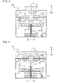
- FIGs. 1 and 2 are perspective views illustrating different states of the shift apparatus 100 in this embodiment.
- the shift apparatus 100 is mounted in a vehicle (not illustrated).
- the up-down direction in this embodiment is stipulated for convenience of explanation and does not restrict a direction in which the shift apparatus 100 is actually used.
- Fig. 3 is a schematic cross-sectional view of the shift apparatus 100 in Fig. 1 in a state in which a manipulation knob 120 is at a protruding position, as taken in a plane that includes line III-III and the up-down direction, which is a direction in which the manipulation knob 120 moves, and as viewed in the direction indicated by the arrows.
- Fig. 4 is a schematic cross-sectional view of the shift apparatus 100 in Fig. 2 in a state in which the manipulation knob 120 is at a stored position, as taken in a plane that includes line IV-IV and the up-down direction, in which the manipulation knob 120 moves, and as viewed in the direction indicated by the arrows.
- the shift apparatus 100 has a case 110 and the manipulation knob 120 as illustrated in Fig. 1 .
- the elements constituting the shift apparatus 100 are stored in the case 110, except the manipulation knob 120.
- the case 110 may be omitted.
- the manipulation knob 120 receives a rotational manipulation performed by the user and switches a transmission accordingly.
- the manipulation knob 120 moves between the protruding position, illustrated in Fig. 1 , at which the manipulation knob 120 protrudes upwardly from the case 110 and the storage position, illustrated in Fig. 2 , at which the manipulation knob 120 is stored in the case 110.
- the ignition switch (not illustrated) of the vehicle is turned on
- the manipulation knob 120 moves from the storage position in Fig. 2 to the protruding position in Fig. 1 ;
- the ignition switch is turned off, the manipulation knob 120 moves from the protruding position in Fig. 1 to the storage position in Fig. 2 .
- the shift apparatus 100 has a motor 130 as illustrated in Fig. 3 .
- the motor 130 in this embodiment is a three-phase brushless motor with four poles and six slots, another brushless motor may be used.
- another type of motor such as a stepping motor may be used.
- the motor 130 includes a cover 131, a rotational shaft 132 protruding upwardly from the inside of the cover 131 to the outside of the cover 131, and a stator 133 provided in the cover 131 so as to be placed around the rotational shaft 132.
- a groove is formed in the cylindrical outer curved surface of the rotational shaft 132 so that it functions as a worm gear.
- Fig. 5 is a conceptual diagram illustrating the layout of part of the elements constituting the motor 130 when viewed from above.
- the rotational shaft 132 rotates around a virtual central line 135 extending in the up-down direction.
- Magnets are provided at the bottom of the rotational shaft 132 so that four poles (NSNS) are evenly placed in the rotational direction; the magnets function as a rotor.
- Six coils (U1, V1, W1, U2, V2, and W2) constituting the stator 133 with six slots are placed around the rotor.
- the coils U1, V1, W1, U2, V2, and W2 are equally spaced in that order at intervals of 60 degrees around the virtual central line 135 in the counterclockwise direction.
- the motor 130 further includes three rotation sensors 134 that are equally spaced at intervals of 60 degrees around the virtual central line 135.
- Each rotation sensor 134 is a magnetic sensor; specifically, the rotation sensor 134 is a Hall element that uses the Hall effect.
- the rotation sensors 134 detect the amount of the rotation of the rotational shaft 132.
- the rotation sensor 134 (HU) is placed between the coil W2 and the coil U1.
- the rotation sensor 134 (HV) is placed between the coil U1 and the coil V1.
- the rotation sensor 134 (HW) is placed between the coil V1 and the coil W1.
- the rotation direction of the rotational shaft 132 and the amount of its rotation are found from a pattern of signals output from the three rotation sensors 134.
- the amount of rotation corresponds to an angle through which the rotational shaft 132 has rotated.
- the shift apparatus 100 further has a lifting shaft 141, a lifting platform 142, and a driven gear piece 143 as illustrated in Fig. 3 .
- the lifting shaft 141 is integrally linked with the manipulation knob 120.
- the lifting shaft 141 rotates around the virtual central line 135 together with the manipulation knob 120.
- the lifting platform 142 rotatably holds the lifting shaft 141.
- the lifting platform 142 is movable in the up-down direction, but its rotation around the virtual central line 135 is restricted by an element (not illustrated).
- the driven gear piece 143 is secured to the lifting platform 142 and is placed around the rotational shaft 132.
- the driven gear piece 143 has a gear groove, which engages the worm gear of the rotational shaft 132, on a surface facing the rotational shaft 132.
- the driven gear piece 143 moves in the up-down direction without rotating. Due to the rotation of the rotational shaft 132, the driven gear piece 143, lifting platform 142, lifting shaft 141, and manipulation knob 120 move together in the up-down direction. Neither the driven gear piece 143 nor lifting platform 142 rotates around the virtual central line 135, but the manipulation knob 120 and lifting shaft 141 are bidirectionally rotatable around the virtual central line 135.
- the manipulation knob 120 and lifting shaft 141 can be rotated independently of the rotation of the rotational shaft 132.
- the worm gear of the rotational shaft 132 and the driven gear piece 143 function as a moving mechanism that moves the manipulation knob 120 along a predetermined path when the rotational shaft 132 rotates.
- the predetermined path is a straight line parallel to the virtual central line 135.
- the lifting platform 142 has two light shielding pieces, a lower light shielding piece 144a and an upper light shielding piece 144b (they may be referred to below as the light shielding piece 144 without being distinguished).
- the lower light shielding piece 144a protrudes downwardly from part of the lifting platform 142
- the upper light shielding piece 144b protrudes upwardly from part of the lifting platform 142.
- the amount of the rotation of the light shielding piece 144 in the up-down direction is equal to the amount of the rotation of the manipulation knob 120.
- the shift apparatus 100 further has a circuit board 150.
- the circuit board 150 is placed so as to define the internal space of the case 110 in the up-down direction.
- the circuit board 150 is disposed between the manipulation knob 120 and the lifting platform 142 so that the lifting shaft 141 passes through the circuit board 150 without contact with it.
- the shift apparatus 100 further has a lower position sensor 151a and an upper position sensor 151b (they may be referred to below as the position sensor 151 without being distinguished).
- the position sensor 151 is a photosensor that indirectly detects the position of the manipulation knob 120 by detecting the position of the light shielding piece 144.
- the lower position sensor 151a which is placed on the bottom surface inside the case 110, detects the position of the lower light shielding piece 144a.
- the lower position sensor 151b which is placed on the lower surface inside the circuit board 150, detects the position of the upper light shielding piece 144b.
- Figs. 7 to 9 illustrate different positional relationships between the position sensor 151 and the light shielding piece 144.
- the position sensor 151 defines an internal space 153 in such a way that an opening 152 is formed at the top or bottom.
- the position sensor 151 uses light to detect whether a substance is present in the internal space 153. If the light shielding piece 144 is present in the internal space 153, the position sensor 151 is turned on. If the light shielding piece 144 is not present in the internal space 153, the position sensor 151 is turned off.
- the amount of the movement of the light shielding piece 144 is equal to the amount of the movement of the manipulation knob 120.
- the position of the end 145 of the light shielding piece 144 and the position of the manipulation knob 120 will be associated with each other.
- the manipulation knob 120 is within a detection range 201.
- the light shielding piece 144 is positioned outside the detection range 201 and only the end 145 of the light shielding piece 144 is positioned in the opening 152, which is a boundary on which the position sensor 151 is switched between its turned-on state and turned-off state as illustrated in Fig.
- the manipulation knob 120 is at a detection position 202.
- the whole of the light shielding piece 144, including the end 145 is positioned outside the internal space 153 as illustrated in Fig. 9 , the manipulation knob 120 is outside the detection range 201.
- the position sensor 151 indirectly detects the position of the manipulation knob 120 through the light shielding piece 144. Specifically, the position sensor 151 detects that the manipulation knob 120 is present at the detection position 202, the manipulation knob 120 is present within the detection range 201, the boundary of which is the detection position 202, and the manipulation knob 120 is not present within the detection range 201, the boundary of which is the detection position 202.
- the relationship between the lower position sensor 151a and the lower light shielding piece 144a is upside down in relation to the relationship between the upper position sensor 151b and the upper light shielding piece 144b.
- the manipulation knob 120 moves between a stop position 203a in a detection range 201a detected by the lower position sensor 151a and a stop position 203b in a detection range 201b detected by the upper position sensor 151b.
- the shift apparatus 100 further has a manipulation detecting unit 160 mounted on the circuit board 150.
- the manipulation detecting unit 160 includes two rotational disks 161, one being disposed on each side of the circuit board 150, and a manipulation amount sensor 162 for the rotational disk 161.
- the lifting shaft 141 is placed so as to pass through the rotational disks 161.
- a groove is formed in the cylindrical side surface of the lifting shaft 141 so as to extend in the up-down direction.
- the engaging pieces of rotational disks 161 engage the groove in the lifting shaft 141.
- Each rotational disk 161 is constrained to the circuit board 150 by a constituent element (not illustrated) so as not to move in the up-down direction while remaining rotatable around the virtual central line 135.
- Fig. 6 is a block diagram illustrating the structure of a control system involved in controlling the up-down movement of the shift apparatus 100.
- the shift apparatus 100 has a motor driving circuit 170, a control unit 180, and a storage device 190, illustrated in Fig. 6 , which are mounted on the circuit board 150 illustrated in Fig. 3 .
- the motor driving circuit 170 controls the motor 130 in response to a command from the control unit 180 to rotate the rotational shaft 132 (see Fig. 3 ) in a desired orientation at a desired speed.
- the motor driving circuit 170 also stops the rotational shaft 132 (see Fig. 3 ).
- the control unit 180 is a central processing unit.
- the storage device 190 is, for example, a random-access memory (RAM).
- the storage device 190 may be another device that can store information.
- the control unit 180 reads a program stored in the storage device 190 and executes the program to perform various types of control for the shift apparatus 100.
- the control unit 180 may be achieved by another constituted element.
- the control unit 180 may be an application-specific integrated circuit (ASIC).
- ASIC application-specific integrated circuit
- the control unit 180 is connected to the motor 130, lower position sensor 151a, upper position sensor 151b, rotation sensor 134 (HU), rotation sensor 134 (HV), and rotation sensor 134 (HW).
- the control unit 180 references a signal pattern output from the rotation sensors 134 and acquires the number of repetitions that occurs at intervals of a certain rotational angle as the amount of rotation.
- the control unit 180 adds the amount of rotation in one direction and subtracts the amount of rotation in a direction opposite to the one direction. When, for example, the manipulation knob 120 moves upwardly from a certain position and then returns to the original position by moving backwardly, the amount of rotation is returned to the previous value.
- control unit 180 When the control unit 180 reads a program stored in the storage device 190 and executes the program, the control unit 180 functions as a motor control unit 181, a storage control unit 182, and an abnormality detecting unit 183.
- the motor control unit 181 rotates or stops the rotational shaft 132 so that the position of the manipulation knob 120 comes close to a target position, according to the amount of the rotation of the rotational shaft 132, the amount being detected by the rotation sensors 134, and to the position of the manipulation knob 120, the position being detected by the position sensor 151.
- the target position may be one of stop positions, including the projecting position in Fig. 1 and the storage position in Fig. 2 , or may be another position.
- the motor control unit 181 stops the manipulation knob 120 at the target position according to a certain amount of rotation from the detection position 202 to the target position, the certain amount having been stored in the storage device 190.
- the storage control unit 182 causes the storage device 190 to store the amount of the rotation of the manipulation knob 120 from a predetermined reference position.
- the storage control unit 182 causes the storage device 190 to store a rotation amount (first amount of rotation) equivalent to the movement of the manipulation knob 120 between the detection position 202 and the reference position.
- the storage control unit 182 may cause the storage device 190 to store a rotation amount (second amount of rotation) obtained when the position of the manipulation knob 120, the position being detected by the position sensor 151, is the reference position, which is the boundary (detection position 202) of the detection range 201.
- the reference position may be within the detection range 201, may be the boundary (detection position 202) of the detection range 201, or may be another position.
- the reference position is set by an abnormality detection method executed by the abnormality detecting unit 183 as described below.
- the abnormality detecting unit 183 detects that at least one of the rotation sensors 134 and the position sensor 151 is abnormal, according to the position of the manipulation knob 120, the position being indicated by the amount of the rotation of the rotational shaft 132, the amount being detected by the rotation sensors 134, and to the position of the manipulation knob 120, the position being indicated by the position sensor 151.
- the abnormality detecting unit 183 makes a first decision as to whether the manipulation knob 120 has reached the detection position 202 from the reference position, according to the rotation amount detected by the rotation sensors 134.
- the abnormality detecting unit 183 also makes a second decision as to whether the manipulation knob 120 has reached the detection position 202 from the reference position, according to the position detected by the position sensor 151.
- the abnormality detecting unit 183 detects an abnormality according to a result in the first decision and a result in the second decision.
- the reference position is distant from the detection position 202.
- the abnormality detecting unit 183 decides whether the manipulation knob 120 has moved from the reference position distant from the detection position 202 and has reached the detection position 202, according to the rotation amount detected by the rotation sensors 134. For example, in the first decision, the abnormality detecting unit 183 decides that the manipulation knob 120 has moved from the reference position and has reached the detection position 202, according to the rotation amount detected by the rotation sensors 134 (first amount of rotation) and to the rotation amount stored in the storage device 190.
- the reference position matches the detection position 202.
- the abnormality detecting unit 183 decides whether the manipulation knob 120 has reached the boundary (detection position 202) of the detection range 201, the boundary being the reference position, from the inside of the detection range 201, according to the rotation amount detected by the rotation sensors 134.
- the abnormality detecting unit 183 decides whether the manipulation knob 120 has reached the boundary (detection position 202) of the detection range 201 from the inside of the detection range 201, according to the position detected by the position sensor 151.
- the abnormality detecting unit 183 decides whether the manipulation knob 120 that had moved from the outside of the detection range 201 to the inside of the detection range 201 has reached the boundary of the detection range 201, according to the rotation amount detected by the rotation sensors 134. Specifically, for example, in the first decision, the abnormality detecting unit 183 decides that the manipulation knob 120 has reached the boundary (detection position 202) of the detection range 201, according to the rotation amount detected by the rotation sensors 134 and to the rotation amount stored in the storage device 190 (second amount of rotation).
- the abnormality detecting unit 183 detects an abnormality in a process in which the motor control unit 181 moves the manipulation knob 120 stopping at the stop position 203 within the detection range 201 as illustrated in Fig. 7 to the outside of the detection range 201 as illustrated in Fig. 9 .
- the first abnormality detection method may be applied to either the lower position sensor 151a or the upper position sensor 151b.
- the stop position 203 distant from the detection position 202 is the reference position.
- the amount Pth of rotation is stored in the storage device 190 in advance; the amount Pth is obtained by adding a threshold to the rotation amount equivalent to a movement from the stop position 203 to the detection position 202. In this example, the amount of rotation is increased in a direction from the stop position 203 toward the detection position 202.
- step 301 the abnormality detecting unit 183 decides whether a start condition has been satisfied. If the motor control unit 181 has begun to move the manipulation knob 120 stopping at the stop position 203 toward the outside of the detection range 201, the abnormality detecting unit 183 decides that the start condition has been satisfied. If the start condition has been satisfied, the abnormality detecting unit 183 proceeds to step 302. If the start condition has not been satisfied, the abnormality detecting unit 183 repeatedly makes a decision in step 301.
- step 302 the abnormality detecting unit 183 causes the storage device 190 to store the amount of rotation at the time at which the start condition has been satisfied, that is, the amount P0 of rotation at the reference position.
- the abnormality detecting unit 183 makes the first decision in step 304.
- the abnormality detecting unit 183 decides whether the manipulation knob 120 has reached the detection position 202 from the reference position (that is, the stop position 203), according to the rotation amount detected by the rotation sensors 134 and to the amounts P0 and Pth of rotation, which are stored in the storage device 190. If ⁇ P is larger than Pth (or ⁇ P is larger than or equal to Pth), the abnormality detecting unit 183 decides that the manipulation knob 120 has reached the detection position 202 from the reference position and proceeds to step 305. If not, the abnormality detecting unit 183 decides that the manipulation knob 120 has not reached the detection position 202 from the reference position and returns to step 303.
- the abnormality detecting unit 183 makes the second decision.
- the abnormality detecting unit 183 decides whether the manipulation knob 120 has reached the detection position 202 from the reference position (that is, the stop position 203), according to the position detected by the position sensor 151. If the position sensor 151 is switched from the turned-on state to the turned-off state, the abnormality detecting unit 183 decides that the manipulation knob 120 has reached the detection position 202 from the reference position and terminates the processing. If the position sensor 151 remains turned on, the abnormality detecting unit 183 decides that the manipulation knob 120 has not reached the detection position 202 from the reference position and proceeds to step 306.
- the abnormality detecting unit 183 decides that the position sensor 151 is abnormal. If it is decided, according to the rotation amount detected by the rotation sensors 134, that the manipulation knob 120 has reached the detection position 202 from the reference position (that is, the stop position 203), but it is not decided, according to the position detected by the position sensor 151, that the manipulation knob 120 has reached the detection position 202 from the reference position, either the position sensor 151 or at least one of the rotation sensors 134 is highly likely to be abnormal. If it is decided that there is an abnormality, the control unit 180 stops the operation of the shift apparatus 100, generates a warning, or performs other processing to deal with the abnormality.
- the abnormality detecting unit 183 detects an abnormality in a process in which the motor control unit 181 moves the manipulation knob 120 present outside the detection range 201 as illustrated in Fig. 9 to the inside of the detection range 201 as illustrated in Fig. 7 , after which the motor control unit 181 further moves the manipulation knob 120 to the outside of the detection range 201.
- the second abnormality detection method may be applied to either the lower position sensor 151a or the upper position sensor 151b.
- the detection position 202 which is the boundary of the detection range 201, is the reference position.
- the amount of rotation is decreased in a direction from the outside of the detection range 201 toward the inside of the detection range 201, and is increased in a direction from the inside of the detection range 201 toward the outside of the detection range 201.
- the abnormality detecting unit 183 decides whether a start condition has been satisfied. Specifically, the abnormality detecting unit 183 decides whether the manipulation knob 120 has reached the boundary of the detection range 201 (that is, the detection position 202) from the outside of the detection range 201, according to the position detected by the position sensor 151. When the position sensor 151 is switched from the turned-off state to the turned-on state, the abnormality detecting unit 183 decides that the manipulation knob 120 has reached the boundary of the detection range 201 from the outside of the detection range 201 and the start condition has been satisfied. If the start condition has been satisfied, the abnormality detecting unit 183 proceeds to step 302. If the start condition has not been satisfied, the abnormality detecting unit 183 repeatedly makes a decision in step 301.
- step 302 the abnormality detecting unit 183 causes the storage device 190 to store the amount of rotation at the time at which the start condition has been satisfied, that is, the amount P0 of rotation at the reference position.
- the abnormality detecting unit 183 makes the first decision in step 304.
- the abnormality detecting unit 183 decides whether the manipulation knob 120 has reached the boundary of the detection range 201 (that is, the detection position 202), the boundary being the reference position, from the inside of the detection range 201, according to the rotation amount detected by the rotation sensors 134.
- the abnormality detecting unit 183 decides that the manipulation knob 120 has reached the boundary of the detection range 201, according to the rotation amount detected by the rotation sensors 134 and to the amounts P0 and Pth of rotation, which are stored in the storage device 190.
- the amount Pth of rotation is set so as to be larger than P0 by a threshold.
- the abnormality detecting unit 183 decides that the manipulation knob 120 has reached the boundary of the detection range 201 from the inside of the detection range 201 and proceeds to step 305. If not, the abnormality detecting unit 183 decides that the manipulation knob 120 has not reached the boundary of the detection range 201 from the inside of the detection range 201 and returns to step 303.
- the abnormality detecting unit 183 makes the second decision.
- the abnormality detecting unit 183 decides whether the manipulation knob 120 has reached the boundary of the detection range 201 (that is, the detection position 202) from the inside of the detection range 201, according to the position detected by the position sensor 151. If the position sensor 151 is switched from the turned-on state to the turned-off state, the abnormality detecting unit 183 decides that the manipulation knob 120 has reached the boundary of the detection range 201 from the inside of the detection range 201 and terminates the processing. If the position sensor 151 remains turned on, the abnormality detecting unit 183 decides that the manipulation knob 120 has not reached the boundary of the detection range 201 from the inside of the detection range 201 and proceeds to step 306.
- the abnormality detecting unit 183 decides that the position sensor 151 is abnormal. If it is decided, according to the rotation amount detected by the rotation sensors 134, that the manipulation knob 120 has reached the boundary of the detection range 201 (that is, the detection position 202) from the inside of the detection range 201, but it is not decided, according to the position detected by the position sensor 151, that the manipulation knob 120 has reached the boundary of the detection range 201 from the inside of the detection range 201, either the position sensor 151 or at least one of the rotation sensors 134 is highly likely to be abnormal. If it is decided that there is an abnormality, the control unit 180 stops the operation of the shift apparatus 100, generates a warning, or performs other processing to deal with the abnormality.
- Fig. 11 illustrates a positional relationship among the lower position sensor 151a, upper position sensor 151b, lower light shielding piece 144a, and upper light shielding piece 144b.
- the reference numerals of the end 145, opening 152, internal space 153, detection range 201, detection position 202, and stop position 203 corresponding to the lower position sensor 151a are suffixed with "a”
- the reference numerals of these elements corresponding to the upper position sensor 151b are suffixed with "b”.
- the positional relationship between the lower position sensor 151a and the upper position sensor 151b may be reversed.
- the abnormality detecting unit 183 detects an abnormality in a process in which the motor control unit 181 moves the manipulation knob 120 located within the detection range 201b of the upper position sensor 151b as illustrated in Fig. 11 to the inside of the detection range 201a of the lower position sensor 151a.
- the detection position 202b of the upper position sensor 151b is the reference position.
- the amount Pth of rotation is stored in the storage device 190 in advance; the amount Pth is obtained by adding a threshold to the rotation amount equivalent to a movement from the detection position 202b of the upper position sensor 151b to the detection position 202a of the lower position sensor 151a. In this example, the amount of rotation is increased in a direction from the detection position 202b of the upper position sensor 151b to the detection position 202a of the lower position sensor 151a.
- step 301 the abnormality detecting unit 183 decides whether a start condition has been satisfied. If the upper position sensor 151b is switched from the turned-on state to the turned-off state, the abnormality detecting unit 183 decides that the start condition has been satisfied. This means that the manipulation knob 120 has moved to below the detection range 201b of the upper position sensor 151b. If the start condition has been satisfied, the abnormality detecting unit 183 proceeds to step 302. If the start condition has not been satisfied, the abnormality detecting unit 183 repeatedly makes a decision in step 301.
- the abnormality detecting unit 183 causes the storage device 190 to store the amount of rotation at the time at which the start condition has been satisfied, that is, the amount P0 of rotation at the reference position (that is, the detection range 201b of the upper position sensor 151b).
- the abnormality detecting unit 183 makes the first decision in step 304.
- the abnormality detecting unit 183 decides whether the manipulation knob 120 has reached the detection position 202a of the lower position sensor 151a from the reference position (that is, the detection position 202b of the upper position sensor 151b), according to the rotation amount detected by the rotation sensors 134.
- the abnormality detecting unit 183 decides that the manipulation knob 120 has moved from the reference position and has reached the detection position 202a of the lower position sensor 151a, according to the rotation amount detected by the rotation sensors 134 and to the amounts P0 and Pth of rotation, which are stored in the storage device 190.
- the abnormality detecting unit 183 decides that the manipulation knob 120 has reached the detection position 202a of the lower position sensor 151a from the detection position 202b of the upper position sensor 151b and proceeds to step 305. If not, the abnormality detecting unit 183 returns to step 303.
- the abnormality detecting unit 183 makes the second decision.
- the abnormality detecting unit 183 decides whether the manipulation knob 120 has reached the detection position 202a of the lower position sensor 151a from the reference position (that is, the detection position 202b of the upper position sensor 151b), according to the position detected by the lower position sensor 151a. If the lower position sensor 151a is switched from the turned-off state to the turned-on state, the abnormality detecting unit 183 decides that the manipulation knob 120 has reached the detection position 202a of the lower position sensor 151a from the reference position and terminates the processing. If the lower position sensor 151a remains turned off, the abnormality detecting unit 183 decides that the manipulation knob 120 has not reached the detection position 202a from the reference position and proceeds to step 306.
- the abnormality detecting unit 183 decides that the position sensor 151 is abnormal. If it is decided, according to the rotation amount detected by the rotation sensors 134, that the manipulation knob 120 has reached the detection position 202a of the lower position sensor 151a from the reference position (that is, the detection position 202b of the upper position sensor 151b), but it is not decided, according to the position detected by the lower position sensor 151a, that the manipulation knob 120 has reached the detection position 202a of the lower position sensor 151a from the reference position, either the position sensor 151 or at least one of the rotation sensors 134 is highly likely to be abnormal. If it is decided that there is an abnormality, the control unit 180 stops the operation of the shift apparatus 100, generates a warning, or performs other processing to deal with the abnormality.
- a difference between a detection result obtained from the position sensor 151 and a detection result obtained from the rotation sensors 134 is used, so an abnormality can be accurately detected with a simple structure.
- the position sensor 151 detects the position of the manipulation knob 120, and the rotation sensors 134 detect the amount of rotation of the rotational shaft 132. Since, in this embodiment, sensors intended for direct detection of different targets are used to detect the position of the same manipulation knob 120 as described above, the possibility that the same abnormality occurs due to the same event is lower than when two sensors of the same type are used to detect the same target, enabling an abnormality to be more accurately detected.
- the structure can be simplified when compared with a case in which a plurality of position sensors 151 are used to redundantly detect their target and a plurality of rotation sensors 134 are also used to redundantly detect their target.
- the present invention can be applied to vehicles, aircraft, ships, and other various conveyances.
Landscapes
- Engineering & Computer Science (AREA)
- General Engineering & Computer Science (AREA)
- Mechanical Engineering (AREA)
- Arrangement Or Mounting Of Control Devices For Change-Speed Gearing (AREA)
- Mechanical Control Devices (AREA)
- Control Of Transmission Device (AREA)
- Gear-Shifting Mechanisms (AREA)
Abstract
Description
- The present invention relates to a shift apparatus and a method of detecting an abnormality in the shift apparatus.
- Some shift apparatuses in vehicles rotate a manipulation knob to switch a transmission. With some of these shift apparatuses, the manipulation knob is stored so as to be flush with a manipulation panel and protrudes from the manipulation panel when an ignition switch is turned on. The manipulation knob is moved by converting the rotation of a motor to a translational motion. A photosensor is used to detect the position of the manipulation knob. PCT Japanese Translation Patent Publication No.
2009-519855 - If the manipulation knob has not been moved to the correct position, the transmission cannot be normally switched. In view of this, two photosensors may be used to detect the position of the manipulation knob redundantly so that even if one of the two photosensors causes an abnormality, the position of the manipulation knob can still be detected. However, when two photosensors of the same type are used, if they cause the same abnormality due to the same event, the abnormality may not be accurately detected. There is also a disadvantage in that since various sensors are included in the shift apparatus, if all sensors are duplicated, the structure becomes complex.
- To address the above situation, the present invention provides a shift apparatus that can accurately detect an abnormality with a simple structure and a method of detecting an abnormality in the shift apparatus.
- A shift apparatus in a first aspect of the present invention is a shift apparatus that uses a manipulation knob to switch a transmission. The shift apparatus has a motor that includes a rotational shaft, a moving mechanism that moves the manipulation knob along a predetermined path when the rotational shaft rotates, rotation sensors that detect the rotation amount of the rotational shaft, a position sensor that detects the position of the manipulation knob, and a control unit. The control unit includes a motor control unit that rotates or stops the rotational shaft so that the position of the manipulation knob comes close to a target position, according to the rotation amount detected by the rotation sensors and to the position detected by the position sensor, and also includes an abnormality detecting unit that detects that at least one of the position sensor and any one of the rotation sensors is abnormal, according to the position of the manipulation knob, the position being indicated by the rotation amount detected by the rotation sensors, and to the position detected by the position sensor.
- According to this structure, it is possible to provide a shift apparatus that can accurately detect an abnormality with a simple structure. Since sensors intended for direct detection of different targets are used to detect the position of the manipulation knob, the possibility that the same abnormality occurs due to the same event is lower than when two sensors of the same type are used to detect the same target, enabling an abnormality to be more accurately detected. The structure can be simplified when compared with a case in which a plurality of position sensors are used to redundantly detect their target and a plurality of rotation sensors are also used to redundantly detect their target.
- Preferably, the position sensor may detect that the manipulation knob is present at a detection position. The abnormality detecting unit may make a first decision as to whether the manipulation knob has reached the detection position from a reference position, according to the rotation amount detected by the rotation sensors. The abnormality detecting unit may also make a second decision as to whether the manipulation knob has reached the detection position from the reference position, according to the position detected by the position sensor. The abnormality detecting unit then detects an abnormality according to a result in the first decision and a result in the second decision.
- Preferably, in the first decision, the abnormality detecting unit may decide whether the manipulation knob has moved from the reference position distant from the detection position and has reached the detection position, according to the rotation amount detected by the rotation sensors.
- Preferably, the shift apparatus in the first aspect of the present invention may further have a storage device that stores a rotation amount equivalent to a movement of the manipulation knob between the detection position and the reference position. In the first decision, the abnormality detecting unit may decide that the manipulation knob has moved from the reference position and has reached the detection position, according to the rotation amount detected by the rotation sensors and to the rotation amount stored in the storage device.
- Preferably, the control unit may further include a storage control unit that, when the manipulation knob has moved from the detection position to the reference position, causes the storage device to store a rotation amount equivalent to the movement of the manipulation knob between the detection position and the reference position.
- Preferably, when the manipulation knob moves from the detection position toward the reference position, the motor control unit may stop the manipulation knob at the reference position according to the rotation amount stored in the storage device.
- Preferably, the position sensor may detect that the manipulation knob is present within a detection range, the boundary of which is the detection position. The reference position may be within the detection range.
- Preferably, the shift apparatus in the first aspect of the present invention may have two position sensors. The manipulation knob may move between a reference position within a detection range detected by one of the two position sensors and a reference position within a detection range detected by the other position sensor.
- Preferably, the position sensor may detect that the manipulation knob is present within a detection range, the boundary of which is the detection position. In the first decision, the abnormality detecting unit may decide whether the manipulation knob has reached the boundary of the detection range, the boundary being the reference position, from the inside of the detection range, according to the rotation amount detected by the rotation sensors. In the second decision, the abnormality detecting unit may decide whether the manipulation knob has reached the boundary of the detection range from the inside of the detection range, according to the position detected by the position sensor.
- Preferably, in the first decision, the abnormality detecting unit may decide whether the manipulation knob that had moved from the outside of the detection range to the inside of the detection range has reached the boundary of the detection range, according to the rotation amount detected by the rotation sensors.
- Preferably, the shift apparatus in the first aspect of the present invention may further have a storage device. The storage unit may further include a storage control unit that causes the storage device to store a rotation amount obtained when the position of the manipulation knob, the position being detected by the position sensor, is the boundary of the detection range. In the first decision, the abnormality detecting unit may decide that the manipulation knob has reached the boundary of the detection range, according to the rotation amount detected by the rotation sensors and to the rotation amount stored in the storage device.
- Preferably, the abnormality detecting unit may obtain the position of the manipulation knob according to the rotation amount detected by the rotation sensors by adding the rotation amount while the rotational shaft is rotating in a first direction and subtracting the rotation amount while the rotational shaft is rotating in a second direction opposite to the first direction.
- Preferably, the position sensor may be a photosensor.
- Preferably, each rotation sensor may be a magnetic sensor.
- Preferably, the predetermined path along which the moving mechanism moves the manipulation knob when the rotational shaft rotates may be a straight line.
- A second aspect of the present invention relates to a method of detecting an abnormality in a shift apparatus that uses a manipulation knob to switch a transmission. The shift apparatus has a motor that includes a rotational shaft, a moving mechanism that moves the manipulation knob along a predetermined path when the rotational shaft rotates, rotation sensors that detect the rotation amount of the rotational shaft, a position sensor that detects the position of the manipulation knob, and a control unit. In the method of detecting an abnormality in the shift apparatus, the control unit rotates or stops the rotational shaft so that the position of the manipulation knob comes close to a target position, according to the rotation amount detected by the rotation sensors and to the position detected by the position sensor. The control unit also detects that at least one of the position sensor and any one of the rotation sensors is abnormal, according to the position of the manipulation knob, the position being indicated by the rotation amount detected by the rotation sensors, and to the position detected by the position sensor.
- In this structure, it is possible to provide a shift apparatus that can accurately detect an abnormality with a simple structure and a method of detecting an abnormality in the shift apparatus.
- The present invention can provide a shift apparatus that can accurately detect an abnormality with a simple structure and a method of detecting an abnormality in the shift apparatus.
-
-
Fig. 1 is a perspective view of a shift apparatus in an embodiment of the present invention; -
Fig. 2 is another perspective view of the shift apparatus inFig. 1 ; -
Fig. 3 is a cross-sectional view of the shift apparatus inFig. 1 as taken along line III-III inFIG. 1 ; -
Fig. 4 is a cross-sectional view of the shift apparatus inFig. 2 as taken along line IV-IV inFIG. 2 ; -
Fig. 5 is a conceptual diagram illustrating the layout of part of the elements constituting a motor; -
Fig. 6 is a block diagram illustrating the structure of a control system of the shift apparatus inFig. 1 ; -
Fig. 7 illustrates a positional relationship between a position sensor and a light shielding piece; -
Fig. 8 illustrates another positional relationship between the position sensor and the shielding piece; -
Fig. 9 illustrates still another positional relationship between the position sensor and the shielding piece; -
Fig. 10 is a flowchart illustrating a method of detecting an abnormality in the shift apparatus inFig. 1 ; and -
Fig. 11 illustrates a positional relationship among two position sensors and two shielding pieces. - A shift apparatus in an embodiment of the present invention will be described.
Figs. 1 and 2 are perspective views illustrating different states of theshift apparatus 100 in this embodiment. Theshift apparatus 100 is mounted in a vehicle (not illustrated). The up-down direction in this embodiment is stipulated for convenience of explanation and does not restrict a direction in which theshift apparatus 100 is actually used. -
Fig. 3 is a schematic cross-sectional view of theshift apparatus 100 inFig. 1 in a state in which amanipulation knob 120 is at a protruding position, as taken in a plane that includes line III-III and the up-down direction, which is a direction in which themanipulation knob 120 moves, and as viewed in the direction indicated by the arrows.Fig. 4 is a schematic cross-sectional view of theshift apparatus 100 inFig. 2 in a state in which themanipulation knob 120 is at a stored position, as taken in a plane that includes line IV-IV and the up-down direction, in which themanipulation knob 120 moves, and as viewed in the direction indicated by the arrows. - The
shift apparatus 100 has acase 110 and themanipulation knob 120 as illustrated inFig. 1 . The elements constituting theshift apparatus 100 are stored in thecase 110, except themanipulation knob 120. Thecase 110 may be omitted. - The
manipulation knob 120 receives a rotational manipulation performed by the user and switches a transmission accordingly. Themanipulation knob 120 moves between the protruding position, illustrated inFig. 1 , at which themanipulation knob 120 protrudes upwardly from thecase 110 and the storage position, illustrated inFig. 2 , at which themanipulation knob 120 is stored in thecase 110. When, for example, the ignition switch (not illustrated) of the vehicle is turned on, themanipulation knob 120 moves from the storage position inFig. 2 to the protruding position inFig. 1 ; when the ignition switch is turned off, themanipulation knob 120 moves from the protruding position inFig. 1 to the storage position inFig. 2 . - The
shift apparatus 100 has amotor 130 as illustrated inFig. 3 . Although themotor 130 in this embodiment is a three-phase brushless motor with four poles and six slots, another brushless motor may be used. Alternatively, another type of motor such as a stepping motor may be used. Themotor 130 includes acover 131, arotational shaft 132 protruding upwardly from the inside of thecover 131 to the outside of thecover 131, and astator 133 provided in thecover 131 so as to be placed around therotational shaft 132. A groove is formed in the cylindrical outer curved surface of therotational shaft 132 so that it functions as a worm gear. -
Fig. 5 is a conceptual diagram illustrating the layout of part of the elements constituting themotor 130 when viewed from above. Therotational shaft 132 rotates around a virtualcentral line 135 extending in the up-down direction. Magnets are provided at the bottom of therotational shaft 132 so that four poles (NSNS) are evenly placed in the rotational direction; the magnets function as a rotor. Six coils (U1, V1, W1, U2, V2, and W2) constituting thestator 133 with six slots are placed around the rotor. The coils U1, V1, W1, U2, V2, and W2 are equally spaced in that order at intervals of 60 degrees around the virtualcentral line 135 in the counterclockwise direction. - The
motor 130 further includes threerotation sensors 134 that are equally spaced at intervals of 60 degrees around the virtualcentral line 135. Eachrotation sensor 134 is a magnetic sensor; specifically, therotation sensor 134 is a Hall element that uses the Hall effect. Therotation sensors 134 detect the amount of the rotation of therotational shaft 132. The rotation sensor 134 (HU) is placed between the coil W2 and the coil U1. The rotation sensor 134 (HV) is placed between the coil U1 and the coil V1. The rotation sensor 134 (HW) is placed between the coil V1 and the coil W1. - The rotation direction of the
rotational shaft 132 and the amount of its rotation are found from a pattern of signals output from the threerotation sensors 134. The amount of rotation corresponds to an angle through which therotational shaft 132 has rotated. - The
shift apparatus 100 further has a liftingshaft 141, alifting platform 142, and a drivengear piece 143 as illustrated inFig. 3 . The liftingshaft 141 is integrally linked with themanipulation knob 120. The liftingshaft 141 rotates around the virtualcentral line 135 together with themanipulation knob 120. Thelifting platform 142 rotatably holds the liftingshaft 141. Thelifting platform 142 is movable in the up-down direction, but its rotation around the virtualcentral line 135 is restricted by an element (not illustrated). The drivengear piece 143 is secured to thelifting platform 142 and is placed around therotational shaft 132. The drivengear piece 143 has a gear groove, which engages the worm gear of therotational shaft 132, on a surface facing therotational shaft 132. - As the
rotational shaft 132 rotates, the drivengear piece 143 moves in the up-down direction without rotating. Due to the rotation of therotational shaft 132, the drivengear piece 143, liftingplatform 142, liftingshaft 141, andmanipulation knob 120 move together in the up-down direction. Neither the drivengear piece 143 nor liftingplatform 142 rotates around the virtualcentral line 135, but themanipulation knob 120 and liftingshaft 141 are bidirectionally rotatable around the virtualcentral line 135. Themanipulation knob 120 and liftingshaft 141 can be rotated independently of the rotation of therotational shaft 132. The worm gear of therotational shaft 132 and the drivengear piece 143 function as a moving mechanism that moves themanipulation knob 120 along a predetermined path when therotational shaft 132 rotates. The predetermined path is a straight line parallel to the virtualcentral line 135. - The
lifting platform 142 has two light shielding pieces, a lowerlight shielding piece 144a and an upperlight shielding piece 144b (they may be referred to below as thelight shielding piece 144 without being distinguished). The lowerlight shielding piece 144a protrudes downwardly from part of thelifting platform 142, and the upperlight shielding piece 144b protrudes upwardly from part of thelifting platform 142. The amount of the rotation of thelight shielding piece 144 in the up-down direction is equal to the amount of the rotation of themanipulation knob 120. - The
shift apparatus 100 further has acircuit board 150. Thecircuit board 150 is placed so as to define the internal space of thecase 110 in the up-down direction. Thecircuit board 150 is disposed between themanipulation knob 120 and thelifting platform 142 so that the liftingshaft 141 passes through thecircuit board 150 without contact with it. - The
shift apparatus 100 further has alower position sensor 151a and anupper position sensor 151b (they may be referred to below as theposition sensor 151 without being distinguished). Theposition sensor 151 is a photosensor that indirectly detects the position of themanipulation knob 120 by detecting the position of thelight shielding piece 144. Thelower position sensor 151a, which is placed on the bottom surface inside thecase 110, detects the position of the lowerlight shielding piece 144a. Thelower position sensor 151b, which is placed on the lower surface inside thecircuit board 150, detects the position of the upperlight shielding piece 144b. -
Figs. 7 to 9 illustrate different positional relationships between theposition sensor 151 and thelight shielding piece 144. As illustrated inFig. 7 , theposition sensor 151 defines aninternal space 153 in such a way that anopening 152 is formed at the top or bottom. Theposition sensor 151 uses light to detect whether a substance is present in theinternal space 153. If thelight shielding piece 144 is present in theinternal space 153, theposition sensor 151 is turned on. If thelight shielding piece 144 is not present in theinternal space 153, theposition sensor 151 is turned off. - In the up-down direction, the amount of the movement of the
light shielding piece 144 is equal to the amount of the movement of themanipulation knob 120. In the description below, therefore, the position of theend 145 of thelight shielding piece 144 and the position of themanipulation knob 120 will be associated with each other. When, for example, theend 145 of thelight shielding piece 144 is positioned in theinternal space 153 as illustrated inFig. 7 , themanipulation knob 120 is within adetection range 201. When thelight shielding piece 144 is positioned outside thedetection range 201 and only theend 145 of thelight shielding piece 144 is positioned in theopening 152, which is a boundary on which theposition sensor 151 is switched between its turned-on state and turned-off state as illustrated inFig. 8 , themanipulation knob 120 is at adetection position 202. When the whole of thelight shielding piece 144, including theend 145, is positioned outside theinternal space 153 as illustrated inFig. 9 , themanipulation knob 120 is outside thedetection range 201. - The
position sensor 151 indirectly detects the position of themanipulation knob 120 through thelight shielding piece 144. Specifically, theposition sensor 151 detects that themanipulation knob 120 is present at thedetection position 202, themanipulation knob 120 is present within thedetection range 201, the boundary of which is thedetection position 202, and themanipulation knob 120 is not present within thedetection range 201, the boundary of which is thedetection position 202. - The relationship between the
lower position sensor 151a and the lowerlight shielding piece 144a is upside down in relation to the relationship between theupper position sensor 151b and the upperlight shielding piece 144b. Themanipulation knob 120 moves between astop position 203a in adetection range 201a detected by thelower position sensor 151a and astop position 203b in adetection range 201b detected by theupper position sensor 151b. - The
shift apparatus 100 further has amanipulation detecting unit 160 mounted on thecircuit board 150. Themanipulation detecting unit 160 includes tworotational disks 161, one being disposed on each side of thecircuit board 150, and amanipulation amount sensor 162 for therotational disk 161. The liftingshaft 141 is placed so as to pass through therotational disks 161. A groove is formed in the cylindrical side surface of the liftingshaft 141 so as to extend in the up-down direction. The engaging pieces ofrotational disks 161 engage the groove in the liftingshaft 141. Eachrotational disk 161 is constrained to thecircuit board 150 by a constituent element (not illustrated) so as not to move in the up-down direction while remaining rotatable around the virtualcentral line 135. - When the lifting
shaft 141 moves in the up-down direction, the engaging piece of eachrotational disk 161 slides in the groove in the liftingshaft 141, so therotational disk 161 does not move in the up-down direction. When the liftingshaft 141 rotates around the virtualcentral line 135, the engaging piece of therotational disk 161 is pressed against the groove in the liftingshaft 141, therotational disk 161 rotates together with the liftingshaft 141. The amount of the rotation of therotational disk 161 is detected by themanipulation amount sensor 162. That is, the rotational manipulation of themanipulation knob 120 is detected by themanipulation amount sensor 162 through the liftingshaft 141 androtational disks 161. A means of detecting the rotational manipulation of themanipulation knob 120 is not limited to this. -
Fig. 6 is a block diagram illustrating the structure of a control system involved in controlling the up-down movement of theshift apparatus 100. Theshift apparatus 100 has amotor driving circuit 170, acontrol unit 180, and astorage device 190, illustrated inFig. 6 , which are mounted on thecircuit board 150 illustrated inFig. 3 . - The
motor driving circuit 170 controls themotor 130 in response to a command from thecontrol unit 180 to rotate the rotational shaft 132 (seeFig. 3 ) in a desired orientation at a desired speed. Themotor driving circuit 170 also stops the rotational shaft 132 (seeFig. 3 ). - The
control unit 180 is a central processing unit. Thestorage device 190 is, for example, a random-access memory (RAM). Thestorage device 190 may be another device that can store information. - The
control unit 180 reads a program stored in thestorage device 190 and executes the program to perform various types of control for theshift apparatus 100. Thecontrol unit 180 may be achieved by another constituted element. For example, thecontrol unit 180 may be an application-specific integrated circuit (ASIC). - The
control unit 180 is connected to themotor 130,lower position sensor 151a,upper position sensor 151b, rotation sensor 134 (HU), rotation sensor 134 (HV), and rotation sensor 134 (HW). Thecontrol unit 180 references a signal pattern output from therotation sensors 134 and acquires the number of repetitions that occurs at intervals of a certain rotational angle as the amount of rotation. To recognize a direction in which themanipulation knob 120 proceeds, thecontrol unit 180 adds the amount of rotation in one direction and subtracts the amount of rotation in a direction opposite to the one direction. When, for example, themanipulation knob 120 moves upwardly from a certain position and then returns to the original position by moving backwardly, the amount of rotation is returned to the previous value. - When the
control unit 180 reads a program stored in thestorage device 190 and executes the program, thecontrol unit 180 functions as amotor control unit 181, astorage control unit 182, and anabnormality detecting unit 183. - The
motor control unit 181 rotates or stops therotational shaft 132 so that the position of themanipulation knob 120 comes close to a target position, according to the amount of the rotation of therotational shaft 132, the amount being detected by therotation sensors 134, and to the position of themanipulation knob 120, the position being detected by theposition sensor 151. The target position may be one of stop positions, including the projecting position inFig. 1 and the storage position inFig. 2 , or may be another position. When, for example, themanipulation knob 120 moves from thedetection position 202 toward the target position, themotor control unit 181 stops themanipulation knob 120 at the target position according to a certain amount of rotation from thedetection position 202 to the target position, the certain amount having been stored in thestorage device 190. - At different times, the
storage control unit 182 causes thestorage device 190 to store the amount of the rotation of themanipulation knob 120 from a predetermined reference position. - When, for example, the
manipulation knob 120 has moved from thedetection position 202 to the reference position, which is the target position, thestorage control unit 182 causes thestorage device 190 to store a rotation amount (first amount of rotation) equivalent to the movement of themanipulation knob 120 between thedetection position 202 and the reference position. - Alternatively, the
storage control unit 182 may cause thestorage device 190 to store a rotation amount (second amount of rotation) obtained when the position of themanipulation knob 120, the position being detected by theposition sensor 151, is the reference position, which is the boundary (detection position 202) of thedetection range 201. - The reference position may be within the
detection range 201, may be the boundary (detection position 202) of thedetection range 201, or may be another position. The reference position is set by an abnormality detection method executed by theabnormality detecting unit 183 as described below. - The
abnormality detecting unit 183 detects that at least one of therotation sensors 134 and theposition sensor 151 is abnormal, according to the position of themanipulation knob 120, the position being indicated by the amount of the rotation of therotational shaft 132, the amount being detected by therotation sensors 134, and to the position of themanipulation knob 120, the position being indicated by theposition sensor 151. - Specifically, for example, the
abnormality detecting unit 183 makes a first decision as to whether themanipulation knob 120 has reached thedetection position 202 from the reference position, according to the rotation amount detected by therotation sensors 134. Theabnormality detecting unit 183 also makes a second decision as to whether themanipulation knob 120 has reached thedetection position 202 from the reference position, according to the position detected by theposition sensor 151. Theabnormality detecting unit 183 then detects an abnormality according to a result in the first decision and a result in the second decision. - There are some different abnormality detection methods based on results in the first decision and second decision.
- In an exemplary abnormality detection method, the reference position is distant from the
detection position 202. In this case, in the first decision, theabnormality detecting unit 183 decides whether themanipulation knob 120 has moved from the reference position distant from thedetection position 202 and has reached thedetection position 202, according to the rotation amount detected by therotation sensors 134. For example, in the first decision, theabnormality detecting unit 183 decides that themanipulation knob 120 has moved from the reference position and has reached thedetection position 202, according to the rotation amount detected by the rotation sensors 134 (first amount of rotation) and to the rotation amount stored in thestorage device 190. - In another exemplary abnormality detection method, the reference position matches the
detection position 202. In this case, in the first decision, theabnormality detecting unit 183 decides whether themanipulation knob 120 has reached the boundary (detection position 202) of thedetection range 201, the boundary being the reference position, from the inside of thedetection range 201, according to the rotation amount detected by therotation sensors 134. In the second decision, theabnormality detecting unit 183 decides whether themanipulation knob 120 has reached the boundary (detection position 202) of thedetection range 201 from the inside of thedetection range 201, according to the position detected by theposition sensor 151. For example, in the first decision, theabnormality detecting unit 183 decides whether themanipulation knob 120 that had moved from the outside of thedetection range 201 to the inside of thedetection range 201 has reached the boundary of thedetection range 201, according to the rotation amount detected by therotation sensors 134. Specifically, for example, in the first decision, theabnormality detecting unit 183 decides that themanipulation knob 120 has reached the boundary (detection position 202) of thedetection range 201, according to the rotation amount detected by therotation sensors 134 and to the rotation amount stored in the storage device 190 (second amount of rotation). - Next, a first abnormality detection method will be described with reference to the flowchart in
Fig. 10 . In the first abnormality detection method, theabnormality detecting unit 183 detects an abnormality in a process in which themotor control unit 181 moves themanipulation knob 120 stopping at thestop position 203 within thedetection range 201 as illustrated inFig. 7 to the outside of thedetection range 201 as illustrated inFig. 9 . The first abnormality detection method may be applied to either thelower position sensor 151a or theupper position sensor 151b. - The
stop position 203 distant from thedetection position 202 is the reference position. The amount Pth of rotation is stored in thestorage device 190 in advance; the amount Pth is obtained by adding a threshold to the rotation amount equivalent to a movement from thestop position 203 to thedetection position 202. In this example, the amount of rotation is increased in a direction from thestop position 203 toward thedetection position 202. - In
step 301, theabnormality detecting unit 183 decides whether a start condition has been satisfied. If themotor control unit 181 has begun to move themanipulation knob 120 stopping at thestop position 203 toward the outside of thedetection range 201, theabnormality detecting unit 183 decides that the start condition has been satisfied. If the start condition has been satisfied, theabnormality detecting unit 183 proceeds to step 302. If the start condition has not been satisfied, theabnormality detecting unit 183 repeatedly makes a decision instep 301. - In
step 302, theabnormality detecting unit 183 causes thestorage device 190 to store the amount of rotation at the time at which the start condition has been satisfied, that is, the amount P0 of rotation at the reference position. - Next, in
step 303, theabnormality detecting unit 183 calculates a difference ΔP between the amount P0 of rotation at the reference position (that is, the stop position 203) and the current amount P of rotation (ΔP = P - P0). - Next, the
abnormality detecting unit 183 makes the first decision instep 304. In the first decision, theabnormality detecting unit 183 decides whether themanipulation knob 120 has reached thedetection position 202 from the reference position (that is, the stop position 203), according to the rotation amount detected by therotation sensors 134 and to the amounts P0 and Pth of rotation, which are stored in thestorage device 190. If ΔP is larger than Pth (or ΔP is larger than or equal to Pth), theabnormality detecting unit 183 decides that themanipulation knob 120 has reached thedetection position 202 from the reference position and proceeds to step 305. If not, theabnormality detecting unit 183 decides that themanipulation knob 120 has not reached thedetection position 202 from the reference position and returns to step 303. - In
step 305, theabnormality detecting unit 183 makes the second decision. In the second decision, theabnormality detecting unit 183 decides whether themanipulation knob 120 has reached thedetection position 202 from the reference position (that is, the stop position 203), according to the position detected by theposition sensor 151. If theposition sensor 151 is switched from the turned-on state to the turned-off state, theabnormality detecting unit 183 decides that themanipulation knob 120 has reached thedetection position 202 from the reference position and terminates the processing. If theposition sensor 151 remains turned on, theabnormality detecting unit 183 decides that themanipulation knob 120 has not reached thedetection position 202 from the reference position and proceeds to step 306. - In
step 306, theabnormality detecting unit 183 decides that theposition sensor 151 is abnormal. If it is decided, according to the rotation amount detected by therotation sensors 134, that themanipulation knob 120 has reached thedetection position 202 from the reference position (that is, the stop position 203), but it is not decided, according to the position detected by theposition sensor 151, that themanipulation knob 120 has reached thedetection position 202 from the reference position, either theposition sensor 151 or at least one of therotation sensors 134 is highly likely to be abnormal. If it is decided that there is an abnormality, thecontrol unit 180 stops the operation of theshift apparatus 100, generates a warning, or performs other processing to deal with the abnormality. - Next, a second abnormality detection method will be described with reference to the flowchart in
Fig. 10 . In the second abnormality detection method, theabnormality detecting unit 183 detects an abnormality in a process in which themotor control unit 181 moves themanipulation knob 120 present outside thedetection range 201 as illustrated inFig. 9 to the inside of thedetection range 201 as illustrated inFig. 7 , after which themotor control unit 181 further moves themanipulation knob 120 to the outside of thedetection range 201. The second abnormality detection method may be applied to either thelower position sensor 151a or theupper position sensor 151b. - The
detection position 202, which is the boundary of thedetection range 201, is the reference position. In this example, the amount of rotation is decreased in a direction from the outside of thedetection range 201 toward the inside of thedetection range 201, and is increased in a direction from the inside of thedetection range 201 toward the outside of thedetection range 201. - In
step 301, theabnormality detecting unit 183 decides whether a start condition has been satisfied. Specifically, theabnormality detecting unit 183 decides whether themanipulation knob 120 has reached the boundary of the detection range 201 (that is, the detection position 202) from the outside of thedetection range 201, according to the position detected by theposition sensor 151. When theposition sensor 151 is switched from the turned-off state to the turned-on state, theabnormality detecting unit 183 decides that themanipulation knob 120 has reached the boundary of thedetection range 201 from the outside of thedetection range 201 and the start condition has been satisfied. If the start condition has been satisfied, theabnormality detecting unit 183 proceeds to step 302. If the start condition has not been satisfied, theabnormality detecting unit 183 repeatedly makes a decision instep 301. - In
step 302, theabnormality detecting unit 183 causes thestorage device 190 to store the amount of rotation at the time at which the start condition has been satisfied, that is, the amount P0 of rotation at the reference position. - Next, in
step 303, theabnormality detecting unit 183 calculates a difference ΔP between the amount P0 of rotation at the reference position (that is, the detection position 202) and the current amount P of rotation (ΔP = P - P0). - Next, the
abnormality detecting unit 183 makes the first decision instep 304. In the first decision, theabnormality detecting unit 183 decides whether themanipulation knob 120 has reached the boundary of the detection range 201 (that is, the detection position 202), the boundary being the reference position, from the inside of thedetection range 201, according to the rotation amount detected by therotation sensors 134. Theabnormality detecting unit 183 decides that themanipulation knob 120 has reached the boundary of thedetection range 201, according to the rotation amount detected by therotation sensors 134 and to the amounts P0 and Pth of rotation, which are stored in thestorage device 190. Since, in this example, thedetection position 202 is the reference position, the amount Pth of rotation, according to which it is decided whether themanipulation knob 120 has reached the boundary of thedetection range 201 from the inside of thedetection range 201, is set so as to be larger than P0 by a threshold. - If ΔP is larger than Pth (or ΔP is larger than or equal to Pth), the
abnormality detecting unit 183 decides that themanipulation knob 120 has reached the boundary of thedetection range 201 from the inside of thedetection range 201 and proceeds to step 305. If not, theabnormality detecting unit 183 decides that themanipulation knob 120 has not reached the boundary of thedetection range 201 from the inside of thedetection range 201 and returns to step 303. - In
step 305, theabnormality detecting unit 183 makes the second decision. In the second decision, theabnormality detecting unit 183 decides whether themanipulation knob 120 has reached the boundary of the detection range 201 (that is, the detection position 202) from the inside of thedetection range 201, according to the position detected by theposition sensor 151. If theposition sensor 151 is switched from the turned-on state to the turned-off state, theabnormality detecting unit 183 decides that themanipulation knob 120 has reached the boundary of thedetection range 201 from the inside of thedetection range 201 and terminates the processing. If theposition sensor 151 remains turned on, theabnormality detecting unit 183 decides that themanipulation knob 120 has not reached the boundary of thedetection range 201 from the inside of thedetection range 201 and proceeds to step 306. - In
step 306, theabnormality detecting unit 183 decides that theposition sensor 151 is abnormal. If it is decided, according to the rotation amount detected by therotation sensors 134, that themanipulation knob 120 has reached the boundary of the detection range 201 (that is, the detection position 202) from the inside of thedetection range 201, but it is not decided, according to the position detected by theposition sensor 151, that themanipulation knob 120 has reached the boundary of thedetection range 201 from the inside of thedetection range 201, either theposition sensor 151 or at least one of therotation sensors 134 is highly likely to be abnormal. If it is decided that there is an abnormality, thecontrol unit 180 stops the operation of theshift apparatus 100, generates a warning, or performs other processing to deal with the abnormality. - Next, a third abnormality detection method will be described with reference to the flowchart in
Fig. 10 .Fig. 11 illustrates a positional relationship among thelower position sensor 151a,upper position sensor 151b, lowerlight shielding piece 144a, and upperlight shielding piece 144b. For the purpose of making a distinction, the reference numerals of theend 145, opening 152,internal space 153,detection range 201,detection position 202, and stopposition 203 corresponding to thelower position sensor 151a are suffixed with "a", and the reference numerals of these elements corresponding to theupper position sensor 151b are suffixed with "b". In the third abnormality detection method, the positional relationship between thelower position sensor 151a and theupper position sensor 151b may be reversed. - In the third abnormality detection method, the
abnormality detecting unit 183 detects an abnormality in a process in which themotor control unit 181 moves themanipulation knob 120 located within thedetection range 201b of theupper position sensor 151b as illustrated inFig. 11 to the inside of thedetection range 201a of thelower position sensor 151a. - The
detection position 202b of theupper position sensor 151b, thedetection position 202b being distant from thedetection position 202a of thelower position sensor 151a, is the reference position. The amount Pth of rotation is stored in thestorage device 190 in advance; the amount Pth is obtained by adding a threshold to the rotation amount equivalent to a movement from thedetection position 202b of theupper position sensor 151b to thedetection position 202a of thelower position sensor 151a. In this example, the amount of rotation is increased in a direction from thedetection position 202b of theupper position sensor 151b to thedetection position 202a of thelower position sensor 151a. - In
step 301, theabnormality detecting unit 183 decides whether a start condition has been satisfied. If theupper position sensor 151b is switched from the turned-on state to the turned-off state, theabnormality detecting unit 183 decides that the start condition has been satisfied. This means that themanipulation knob 120 has moved to below thedetection range 201b of theupper position sensor 151b. If the start condition has been satisfied, theabnormality detecting unit 183 proceeds to step 302. If the start condition has not been satisfied, theabnormality detecting unit 183 repeatedly makes a decision instep 301. - In
step 302, theabnormality detecting unit 183 causes thestorage device 190 to store the amount of rotation at the time at which the start condition has been satisfied, that is, the amount P0 of rotation at the reference position (that is, thedetection range 201b of theupper position sensor 151b). - Next, in
step 303, theabnormality detecting unit 183 calculates a difference ΔP between the amount P0 of rotation at the reference position (that is, thedetection range 201b of theupper position sensor 151b) and the current amount P of rotation (ΔP = P - P0). - Next, the
abnormality detecting unit 183 makes the first decision instep 304. In the first decision, theabnormality detecting unit 183 decides whether themanipulation knob 120 has reached thedetection position 202a of thelower position sensor 151a from the reference position (that is, thedetection position 202b of theupper position sensor 151b), according to the rotation amount detected by therotation sensors 134. Theabnormality detecting unit 183 decides that themanipulation knob 120 has moved from the reference position and has reached thedetection position 202a of thelower position sensor 151a, according to the rotation amount detected by therotation sensors 134 and to the amounts P0 and Pth of rotation, which are stored in thestorage device 190. - If ΔP is larger than Pth (or ΔP is larger than or equal to Pth), the
abnormality detecting unit 183 decides that themanipulation knob 120 has reached thedetection position 202a of thelower position sensor 151a from thedetection position 202b of theupper position sensor 151b and proceeds to step 305. If not, theabnormality detecting unit 183 returns to step 303. - In
step 305, theabnormality detecting unit 183 makes the second decision. In the second decision, theabnormality detecting unit 183 decides whether themanipulation knob 120 has reached thedetection position 202a of thelower position sensor 151a from the reference position (that is, thedetection position 202b of theupper position sensor 151b), according to the position detected by thelower position sensor 151a. If thelower position sensor 151a is switched from the turned-off state to the turned-on state, theabnormality detecting unit 183 decides that themanipulation knob 120 has reached thedetection position 202a of thelower position sensor 151a from the reference position and terminates the processing. If thelower position sensor 151a remains turned off, theabnormality detecting unit 183 decides that themanipulation knob 120 has not reached thedetection position 202a from the reference position and proceeds to step 306. - In
step 306, theabnormality detecting unit 183 decides that theposition sensor 151 is abnormal. If it is decided, according to the rotation amount detected by therotation sensors 134, that themanipulation knob 120 has reached thedetection position 202a of thelower position sensor 151a from the reference position (that is, thedetection position 202b of theupper position sensor 151b), but it is not decided, according to the position detected by thelower position sensor 151a, that themanipulation knob 120 has reached thedetection position 202a of thelower position sensor 151a from the reference position, either theposition sensor 151 or at least one of therotation sensors 134 is highly likely to be abnormal. If it is decided that there is an abnormality, thecontrol unit 180 stops the operation of theshift apparatus 100, generates a warning, or performs other processing to deal with the abnormality. - According to this embodiment, a difference between a detection result obtained from the
position sensor 151 and a detection result obtained from therotation sensors 134 is used, so an abnormality can be accurately detected with a simple structure. Theposition sensor 151 detects the position of themanipulation knob 120, and therotation sensors 134 detect the amount of rotation of therotational shaft 132. Since, in this embodiment, sensors intended for direct detection of different targets are used to detect the position of thesame manipulation knob 120 as described above, the possibility that the same abnormality occurs due to the same event is lower than when two sensors of the same type are used to detect the same target, enabling an abnormality to be more accurately detected. In this embodiment, the structure can be simplified when compared with a case in which a plurality ofposition sensors 151 are used to redundantly detect their target and a plurality ofrotation sensors 134 are also used to redundantly detect their target. - The present invention is not limited to the embodiment described above. That is, a person having ordinary skill in the art may make various modifications, combinations, subcombinations, and replacements for the constituent elements in the above embodiment, without departing from the technical range of the present invention or an equivalent range of the technical range.
- The present invention can be applied to vehicles, aircraft, ships, and other various conveyances.
Claims (16)
- A shift apparatus (100) comprising:a manipulation knob (120) used to switch a transmission;a motor (130) that includes a rotational shaft (132);a moving mechanism that moves the manipulation knob (120) along a predetermined path when the rotational shaft (132) rotates;a rotation sensor (134) that detects a rotation amount of the rotational shaft (132);a position sensor (151) that detects a position of the manipulation knob (120); anda control unit (180); whereinthe control unit (180) includes
a motor control unit (181) that rotates or stops the rotational shaft (132) so that the position of the manipulation knob (120) comes close to a target position, according to the rotation amount detected by the rotation sensor (134) and to the position detected by the position sensor (151), and
an abnormality detecting unit (183) that detects that at least one of the position sensor (151) and the rotation sensor (134) is abnormal, according to the position of the manipulation knob (120), the position being indicated by the rotation amount detected by the rotation sensor (134), and to the position detected by the position sensor (151). - The shift apparatus according to Claim 1, wherein:the position sensor (151) detects that the manipulation knob (120) is present at a detection position; andthe abnormality detecting unit (183)makes a first decision as to whether the manipulation knob (120) has reached the detection position from a reference position, according to the rotation amount detected by the rotation sensor (134),
makes a second decision as to whether the manipulation knob (120) has reached the detection position from the reference position, according to the position detected by the position sensor (151), and
detects an abnormality according to a result in the first decision and a result in the second decision. - The shift apparatus according to Claim 2, wherein, in the first decision, the abnormality detecting unit (183) decides whether the manipulation knob (120) has moved from the reference position distant from the detection position and has reached the detection position, according to the rotation amount detected by the rotation sensor (134).
- The shift apparatus according to Claim 3, further comprising a storage device (190) that stores a rotation amount equivalent to a movement of the manipulation knob (120) between the detection position and the reference position, wherein
in the first decision, the abnormality detecting unit (183) decides that the manipulation knob (120) has moved from the reference position and has reached the detection position, according to the rotation amount detected by the rotation sensor (134) and to the rotation amount stored in the storage device (190). - The shift apparatus according to Claim 4, wherein the control unit (180) further includes a storage control unit (182) that, when the manipulation knob (120) has moved from the detection position to the reference position, causes the storage device (190) to store the rotation amount equivalent to the movement of the manipulation knob (120) between the detection position and the reference position.
- The shift apparatus according to Claim 4 or 5, wherein when the manipulation knob (120) moves from the detection position toward the reference position, the motor control unit (181) stops the manipulation knob (120) at the reference position according to the rotation amount stored in the storage device (190).
- The shift apparatus according to any one of Claims 3 to 6, wherein:the position sensor (151) detects that the manipulation knob (120) is present within a detection range, a boundary of which is the detection position; andthe reference position is within the detection range.
- The shift apparatus according to Claim 7, wherein:two position sensors (151) are provided; andthe manipulation knob (120) moves between a reference position within a detection range detected by one of the two position sensors (151) and a reference position within a detection range detected by another of the two position sensors (151).
- The shift apparatus according to Claim 2, wherein:the position sensor (151) detects that the manipulation knob (120) is present within a detection range, a boundary of which is the detection position; andthe abnormality detecting unit (183) decides in the first decision, whether the manipulation knob (120) has reached the boundary of the detection range, the boundary being the reference position, from an inside of the detection range, according to the rotation amount detected by the rotation sensor (134), andin the second decision, whether the manipulation knob (120) has reached the boundary of the detection range from the inside of the detection range, according to the position detected by the position sensor (151).
- The shift apparatus according to Claim 9, wherein, in the first decision, the abnormality detecting unit (183) decides whether the manipulation knob (120) that had moved from an outside of the detection range to the inside of the detection range has reached the boundary of the detection range, according to the rotation amount detected by the rotation sensor (134).
- The shift apparatus according to Claim 9, further comprising a storage device (190), wherein:the storage unit further includes a storage control unit (182) that causes the storage device (190) to store a rotation amount obtained when the position of the manipulation knob (120), the position being detected by the position sensor (151), is the boundary of the detection range; andin the first decision, the abnormality detecting unit (183) decides that the manipulation knob (120) has reached the boundary of the detection range, according to the rotation amount detected by the rotation sensor (134) and to the rotation amount stored in the storage device (190).
- The shift apparatus according to any one of Claims 1 to 11, wherein the abnormality detecting unit (183) obtains the position of the manipulation knob (120) according to the rotation amount detected by the rotation sensor (134) by adding the rotation amount while the rotational shaft (132) is rotating in a first direction and subtracting the rotation amount while the rotational shaft (132) is rotating in a second direction opposite to the first direction.
- The shift apparatus according to any one of Claims 1 to 12, wherein the position sensor (151) is a photosensor.
- The shift apparatus according to any one of Claims 1 to 13, wherein the rotation sensor (134) is a magnetic sensor.
- The shift apparatus according to any one of Claims 1 to 14, wherein the predetermined path is a straight line.
- A method of detecting an abnormality in a shift apparatus (100), wherein:the shift apparatus (100) hasa manipulation knob (120) used to switch a transmission,a motor (130) that includes a rotational shaft (132),a moving mechanism that moves the manipulation knob (120) along a predetermined path when the rotational shaft (132) rotates,a rotation sensor (134) that detects a rotation amount of the rotational shaft (132),a position sensor (151) that detects a position of the manipulation knob (120), anda control unit (180);the control unit (180) rotates or stops the rotational shaft (132) so that the position of the manipulation knob (120) comes close to a target position, according to the rotation amount detected by the rotation sensor (134) and to the position detected by the position sensor (151); and
the control unit (180) detects that at least one of the position sensor (151) and the rotation sensor (134) is abnormal, according to the position of the manipulation knob (120), the position being indicated by the rotation amount detected by the rotation sensor (134), and to the position detected by the position sensor (151).
Applications Claiming Priority (1)
| Application Number | Priority Date | Filing Date | Title |
|---|---|---|---|
| JP2015199808A JP6474706B2 (en) | 2015-10-07 | 2015-10-07 | Shift device and shift device abnormality detection method |
Publications (3)
| Publication Number | Publication Date |
|---|---|
| EP3153745A2 true EP3153745A2 (en) | 2017-04-12 |
| EP3153745A3 EP3153745A3 (en) | 2017-05-10 |
| EP3153745B1 EP3153745B1 (en) | 2022-08-17 |
Family
ID=57121072
Family Applications (1)
| Application Number | Title | Priority Date | Filing Date |
|---|---|---|---|
| EP16192206.7A Active EP3153745B1 (en) | 2015-10-07 | 2016-10-04 | Shift apparatus and shift apparatus abnormality detection method |
Country Status (2)
| Country | Link |
|---|---|
| EP (1) | EP3153745B1 (en) |
| JP (1) | JP6474706B2 (en) |
Cited By (3)
| Publication number | Priority date | Publication date | Assignee | Title |
|---|---|---|---|---|
| CN107654589A (en) * | 2017-10-25 | 2018-02-02 | 盐城市步高汽配制造有限公司 | One kind two keeps off countershaft transmission structure and its process for gear |
| CN108317242A (en) * | 2018-04-21 | 2018-07-24 | 浙江科思泰智能科技有限公司 | The knob jacking system of knob selector |
| CN111006007A (en) * | 2018-10-08 | 2020-04-14 | 上海汽车集团股份有限公司 | Automobile, knob gear shifting mechanism and control method thereof |
Families Citing this family (1)
| Publication number | Priority date | Publication date | Assignee | Title |
|---|---|---|---|---|
| JP7213201B2 (en) * | 2020-03-30 | 2023-01-26 | 本田技研工業株式会社 | shift device |
Citations (1)
| Publication number | Priority date | Publication date | Assignee | Title |
|---|---|---|---|---|
| JP2009519855A (en) | 2005-12-20 | 2009-05-21 | レムフェルダー エレクトロニック ゲゼルシャフト ミット ベシュレンクテル ハフツング | Shift device for shifting a vehicle transmission |
Family Cites Families (9)
| Publication number | Priority date | Publication date | Assignee | Title |
|---|---|---|---|---|
| JPH035625A (en) * | 1989-05-30 | 1991-01-11 | Toshiba Corp | Control device for cooking apparatus |
| US6550351B1 (en) * | 1999-08-06 | 2003-04-22 | Stoneridge Control Devices, Inc. | Transmission range selector system |
| JP2003154869A (en) * | 2001-11-22 | 2003-05-27 | Tokai Rika Co Ltd | Shift device |
| US7571662B2 (en) * | 2004-08-18 | 2009-08-11 | Jaguars Cars Limited | Selector mechanism for a motor vehicle transmission |
| DE102004054264B4 (en) * | 2004-11-09 | 2007-08-09 | Zf Friedrichshafen Ag | Actuation device with rotary switch |
| JP4899783B2 (en) * | 2006-10-24 | 2012-03-21 | トヨタ自動車株式会社 | Control device for shift switching mechanism, control method, program for realizing the control method on a computer, and recording medium on which the program is recorded |
| JP2008153121A (en) * | 2006-12-19 | 2008-07-03 | Tokai Rika Co Ltd | Rotary switch |
| CA2817567A1 (en) * | 2010-11-09 | 2012-05-18 | Kostal Of America | Electronic selector switch |
| JP2012235613A (en) * | 2011-04-28 | 2012-11-29 | Nsk Ltd | Actuator, motor control system and motor control method |
-
2015
- 2015-10-07 JP JP2015199808A patent/JP6474706B2/en active Active
-
2016
- 2016-10-04 EP EP16192206.7A patent/EP3153745B1/en active Active
Patent Citations (1)
| Publication number | Priority date | Publication date | Assignee | Title |
|---|---|---|---|---|
| JP2009519855A (en) | 2005-12-20 | 2009-05-21 | レムフェルダー エレクトロニック ゲゼルシャフト ミット ベシュレンクテル ハフツング | Shift device for shifting a vehicle transmission |
Cited By (5)
| Publication number | Priority date | Publication date | Assignee | Title |
|---|---|---|---|---|
| CN107654589A (en) * | 2017-10-25 | 2018-02-02 | 盐城市步高汽配制造有限公司 | One kind two keeps off countershaft transmission structure and its process for gear |
| CN107654589B (en) * | 2017-10-25 | 2020-04-10 | 盐城市步高汽配制造有限公司 | Two-gear intermediate shaft transmission structure and gear shifting method thereof |
| CN108317242A (en) * | 2018-04-21 | 2018-07-24 | 浙江科思泰智能科技有限公司 | The knob jacking system of knob selector |
| CN111006007A (en) * | 2018-10-08 | 2020-04-14 | 上海汽车集团股份有限公司 | Automobile, knob gear shifting mechanism and control method thereof |
| CN111006007B (en) * | 2018-10-08 | 2022-02-25 | 上海汽车集团股份有限公司 | Automobile, knob gear shifting mechanism and control method thereof |
Also Published As
| Publication number | Publication date |
|---|---|
| EP3153745A3 (en) | 2017-05-10 |
| JP2017071324A (en) | 2017-04-13 |
| EP3153745B1 (en) | 2022-08-17 |
| JP6474706B2 (en) | 2019-02-27 |
Similar Documents
| Publication | Publication Date | Title |
|---|---|---|
| EP3153745A2 (en) | Shift apparatus and shift apparatus abnormality detection method | |
| US10138999B2 (en) | Shift range control apparatus | |
| JP6572794B2 (en) | Motor control device | |
| JP6659416B2 (en) | Vehicle shift device | |
| JP6647923B2 (en) | Electromechanical device, control method for electromechanical device, and control program for electromechanical device | |
| US9122252B2 (en) | Motor control apparatus | |
| JP5831766B2 (en) | Control device and shift-by-wire system using the same | |
| JP5874979B2 (en) | Range switching device | |
| WO2018159354A1 (en) | Shift range control device | |
| KR101312178B1 (en) | Column Type Transmission Lever Assembly | |
| US8530770B2 (en) | Switch apparatus | |
| JP6436048B2 (en) | Motor control device | |
| CN114076115B (en) | Oscillating positioning structure, resetting method and device, electric fan and readable storage medium | |
| WO2017082072A1 (en) | Electromechanical device, motor control device and rotation control method | |
| US20160379777A1 (en) | Operation device | |
| JP4700632B2 (en) | Multi-directional operation device | |
| JP2014173606A (en) | Range changeover device | |
| US20220333686A1 (en) | Shift device | |
| JP6425350B2 (en) | Electro-mechanical device and stop control method of electro-mechanical device | |
| JP2002120645A (en) | Device for canceling direction indicator lever | |
| JP2020157929A (en) | Shifter | |
| JP2011162997A (en) | Power window switch device | |
| CN116915015A (en) | Limited angle stepping motor and control method | |
| JP2011034198A (en) | Input device | |
| US11505066B2 (en) | Operating apparatus for a vehicle component and method for producing feedback |
Legal Events
| Date | Code | Title | Description |
|---|---|---|---|
| PUAI | Public reference made under article 153(3) epc to a published international application that has entered the european phase |
Free format text: ORIGINAL CODE: 0009012 |
|
| STAA | Information on the status of an ep patent application or granted ep patent |
Free format text: STATUS: THE APPLICATION HAS BEEN PUBLISHED |
|
| PUAL | Search report despatched |
Free format text: ORIGINAL CODE: 0009013 |
|
| AK | Designated contracting states |
Kind code of ref document: A2 Designated state(s): AL AT BE BG CH CY CZ DE DK EE ES FI FR GB GR HR HU IE IS IT LI LT LU LV MC MK MT NL NO PL PT RO RS SE SI SK SM TR |
|
| AX | Request for extension of the european patent |
Extension state: BA ME |
|
| AK | Designated contracting states |
Kind code of ref document: A3 Designated state(s): AL AT BE BG CH CY CZ DE DK EE ES FI FR GB GR HR HU IE IS IT LI LT LU LV MC MK MT NL NO PL PT RO RS SE SI SK SM TR |
|
| AX | Request for extension of the european patent |
Extension state: BA ME |
|
| RIC1 | Information provided on ipc code assigned before grant |
Ipc: F16H 59/08 20060101AFI20170406BHEP Ipc: F16H 61/12 20100101ALI20170406BHEP |
|
| STAA | Information on the status of an ep patent application or granted ep patent |
Free format text: STATUS: REQUEST FOR EXAMINATION WAS MADE |
|
| 17P | Request for examination filed |
Effective date: 20171017 |
|
| RBV | Designated contracting states (corrected) |
Designated state(s): AL AT BE BG CH CY CZ DE DK EE ES FI FR GB GR HR HU IE IS IT LI LT LU LV MC MK MT NL NO PL PT RO RS SE SI SK SM TR |
|
| RAP1 | Party data changed (applicant data changed or rights of an application transferred) |
Owner name: ALPS ALPINE CO., LTD. |
|
| STAA | Information on the status of an ep patent application or granted ep patent |
Free format text: STATUS: EXAMINATION IS IN PROGRESS |
|
| 17Q | First examination report despatched |
Effective date: 20190926 |
|
| STAA | Information on the status of an ep patent application or granted ep patent |
Free format text: STATUS: EXAMINATION IS IN PROGRESS |
|
| STAA | Information on the status of an ep patent application or granted ep patent |
Free format text: STATUS: EXAMINATION IS IN PROGRESS |
|
| GRAP | Despatch of communication of intention to grant a patent |
Free format text: ORIGINAL CODE: EPIDOSNIGR1 |
|
| STAA | Information on the status of an ep patent application or granted ep patent |
Free format text: STATUS: GRANT OF PATENT IS INTENDED |
|
| INTG | Intention to grant announced |
Effective date: 20220422 |
|
| GRAS | Grant fee paid |
Free format text: ORIGINAL CODE: EPIDOSNIGR3 |
|
| GRAA | (expected) grant |
Free format text: ORIGINAL CODE: 0009210 |
|
| STAA | Information on the status of an ep patent application or granted ep patent |
Free format text: STATUS: THE PATENT HAS BEEN GRANTED |
|
| AK | Designated contracting states |
Kind code of ref document: B1 Designated state(s): AL AT BE BG CH CY CZ DE DK EE ES FI FR GB GR HR HU IE IS IT LI LT LU LV MC MK MT NL NO PL PT RO RS SE SI SK SM TR |
|
| REG | Reference to a national code |
Ref country code: CH Ref legal event code: EP |
|
| REG | Reference to a national code |
Ref country code: DE Ref legal event code: R096 Ref document number: 602016074312 Country of ref document: DE |
|
| REG | Reference to a national code |
Ref country code: IE Ref legal event code: FG4D |
|
| REG | Reference to a national code |
Ref country code: AT Ref legal event code: REF Ref document number: 1512393 Country of ref document: AT Kind code of ref document: T Effective date: 20220915 |
|
| REG | Reference to a national code |
Ref country code: NL Ref legal event code: MP Effective date: 20220817 |
|
| REG | Reference to a national code |
Ref country code: LT Ref legal event code: MG9D |
|
| PG25 | Lapsed in a contracting state [announced via postgrant information from national office to epo] |
Ref country code: SE Free format text: LAPSE BECAUSE OF FAILURE TO SUBMIT A TRANSLATION OF THE DESCRIPTION OR TO PAY THE FEE WITHIN THE PRESCRIBED TIME-LIMIT Effective date: 20220817 Ref country code: RS Free format text: LAPSE BECAUSE OF FAILURE TO SUBMIT A TRANSLATION OF THE DESCRIPTION OR TO PAY THE FEE WITHIN THE PRESCRIBED TIME-LIMIT Effective date: 20220817 Ref country code: PT Free format text: LAPSE BECAUSE OF FAILURE TO SUBMIT A TRANSLATION OF THE DESCRIPTION OR TO PAY THE FEE WITHIN THE PRESCRIBED TIME-LIMIT Effective date: 20221219 Ref country code: NO Free format text: LAPSE BECAUSE OF FAILURE TO SUBMIT A TRANSLATION OF THE DESCRIPTION OR TO PAY THE FEE WITHIN THE PRESCRIBED TIME-LIMIT Effective date: 20221117 Ref country code: NL Free format text: LAPSE BECAUSE OF FAILURE TO SUBMIT A TRANSLATION OF THE DESCRIPTION OR TO PAY THE FEE WITHIN THE PRESCRIBED TIME-LIMIT Effective date: 20220817 Ref country code: LV Free format text: LAPSE BECAUSE OF FAILURE TO SUBMIT A TRANSLATION OF THE DESCRIPTION OR TO PAY THE FEE WITHIN THE PRESCRIBED TIME-LIMIT Effective date: 20220817 Ref country code: LT Free format text: LAPSE BECAUSE OF FAILURE TO SUBMIT A TRANSLATION OF THE DESCRIPTION OR TO PAY THE FEE WITHIN THE PRESCRIBED TIME-LIMIT Effective date: 20220817 Ref country code: FI Free format text: LAPSE BECAUSE OF FAILURE TO SUBMIT A TRANSLATION OF THE DESCRIPTION OR TO PAY THE FEE WITHIN THE PRESCRIBED TIME-LIMIT Effective date: 20220817 Ref country code: ES Free format text: LAPSE BECAUSE OF FAILURE TO SUBMIT A TRANSLATION OF THE DESCRIPTION OR TO PAY THE FEE WITHIN THE PRESCRIBED TIME-LIMIT Effective date: 20220817 |
|
| REG | Reference to a national code |
Ref country code: AT Ref legal event code: MK05 Ref document number: 1512393 Country of ref document: AT Kind code of ref document: T Effective date: 20220817 |
|
| PG25 | Lapsed in a contracting state [announced via postgrant information from national office to epo] |
Ref country code: PL Free format text: LAPSE BECAUSE OF FAILURE TO SUBMIT A TRANSLATION OF THE DESCRIPTION OR TO PAY THE FEE WITHIN THE PRESCRIBED TIME-LIMIT Effective date: 20220817 Ref country code: IS Free format text: LAPSE BECAUSE OF FAILURE TO SUBMIT A TRANSLATION OF THE DESCRIPTION OR TO PAY THE FEE WITHIN THE PRESCRIBED TIME-LIMIT Effective date: 20221217 Ref country code: HR Free format text: LAPSE BECAUSE OF FAILURE TO SUBMIT A TRANSLATION OF THE DESCRIPTION OR TO PAY THE FEE WITHIN THE PRESCRIBED TIME-LIMIT Effective date: 20220817 Ref country code: GR Free format text: LAPSE BECAUSE OF FAILURE TO SUBMIT A TRANSLATION OF THE DESCRIPTION OR TO PAY THE FEE WITHIN THE PRESCRIBED TIME-LIMIT Effective date: 20221118 |
|
| PG25 | Lapsed in a contracting state [announced via postgrant information from national office to epo] |
Ref country code: SM Free format text: LAPSE BECAUSE OF FAILURE TO SUBMIT A TRANSLATION OF THE DESCRIPTION OR TO PAY THE FEE WITHIN THE PRESCRIBED TIME-LIMIT Effective date: 20220817 Ref country code: RO Free format text: LAPSE BECAUSE OF FAILURE TO SUBMIT A TRANSLATION OF THE DESCRIPTION OR TO PAY THE FEE WITHIN THE PRESCRIBED TIME-LIMIT Effective date: 20220817 Ref country code: DK Free format text: LAPSE BECAUSE OF FAILURE TO SUBMIT A TRANSLATION OF THE DESCRIPTION OR TO PAY THE FEE WITHIN THE PRESCRIBED TIME-LIMIT Effective date: 20220817 Ref country code: CZ Free format text: LAPSE BECAUSE OF FAILURE TO SUBMIT A TRANSLATION OF THE DESCRIPTION OR TO PAY THE FEE WITHIN THE PRESCRIBED TIME-LIMIT Effective date: 20220817 Ref country code: AT Free format text: LAPSE BECAUSE OF FAILURE TO SUBMIT A TRANSLATION OF THE DESCRIPTION OR TO PAY THE FEE WITHIN THE PRESCRIBED TIME-LIMIT Effective date: 20220817 |
|
| REG | Reference to a national code |
Ref country code: DE Ref legal event code: R097 Ref document number: 602016074312 Country of ref document: DE |
|
| PG25 | Lapsed in a contracting state [announced via postgrant information from national office to epo] |
Ref country code: SK Free format text: LAPSE BECAUSE OF FAILURE TO SUBMIT A TRANSLATION OF THE DESCRIPTION OR TO PAY THE FEE WITHIN THE PRESCRIBED TIME-LIMIT Effective date: 20220817 Ref country code: MC Free format text: LAPSE BECAUSE OF FAILURE TO SUBMIT A TRANSLATION OF THE DESCRIPTION OR TO PAY THE FEE WITHIN THE PRESCRIBED TIME-LIMIT Effective date: 20220817 Ref country code: EE Free format text: LAPSE BECAUSE OF FAILURE TO SUBMIT A TRANSLATION OF THE DESCRIPTION OR TO PAY THE FEE WITHIN THE PRESCRIBED TIME-LIMIT Effective date: 20220817 |
|
| REG | Reference to a national code |
Ref country code: CH Ref legal event code: PL |
|
| PLBE | No opposition filed within time limit |
Free format text: ORIGINAL CODE: 0009261 |
|
| STAA | Information on the status of an ep patent application or granted ep patent |
Free format text: STATUS: NO OPPOSITION FILED WITHIN TIME LIMIT |
|
| REG | Reference to a national code |
Ref country code: BE Ref legal event code: MM Effective date: 20221031 |
|
| PG25 | Lapsed in a contracting state [announced via postgrant information from national office to epo] |
Ref country code: LU Free format text: LAPSE BECAUSE OF NON-PAYMENT OF DUE FEES Effective date: 20221004 Ref country code: AL Free format text: LAPSE BECAUSE OF FAILURE TO SUBMIT A TRANSLATION OF THE DESCRIPTION OR TO PAY THE FEE WITHIN THE PRESCRIBED TIME-LIMIT Effective date: 20220817 |
|
| 26N | No opposition filed |
Effective date: 20230519 |
|
| GBPC | Gb: european patent ceased through non-payment of renewal fee |
Effective date: 20221117 |
|
| PG25 | Lapsed in a contracting state [announced via postgrant information from national office to epo] |
Ref country code: LI Free format text: LAPSE BECAUSE OF NON-PAYMENT OF DUE FEES Effective date: 20221031 Ref country code: FR Free format text: LAPSE BECAUSE OF NON-PAYMENT OF DUE FEES Effective date: 20221017 Ref country code: CH Free format text: LAPSE BECAUSE OF NON-PAYMENT OF DUE FEES Effective date: 20221031 |
|
| PG25 | Lapsed in a contracting state [announced via postgrant information from national office to epo] |
Ref country code: SI Free format text: LAPSE BECAUSE OF FAILURE TO SUBMIT A TRANSLATION OF THE DESCRIPTION OR TO PAY THE FEE WITHIN THE PRESCRIBED TIME-LIMIT Effective date: 20220817 |
|
| PG25 | Lapsed in a contracting state [announced via postgrant information from national office to epo] |
Ref country code: BE Free format text: LAPSE BECAUSE OF NON-PAYMENT OF DUE FEES Effective date: 20221031 |
|
| PG25 | Lapsed in a contracting state [announced via postgrant information from national office to epo] |
Ref country code: IE Free format text: LAPSE BECAUSE OF NON-PAYMENT OF DUE FEES Effective date: 20221004 Ref country code: GB Free format text: LAPSE BECAUSE OF NON-PAYMENT OF DUE FEES Effective date: 20221117 |
|
| PGFP | Annual fee paid to national office [announced via postgrant information from national office to epo] |
Ref country code: DE Payment date: 20231020 Year of fee payment: 8 |
|
| PG25 | Lapsed in a contracting state [announced via postgrant information from national office to epo] |
Ref country code: HU Free format text: LAPSE BECAUSE OF FAILURE TO SUBMIT A TRANSLATION OF THE DESCRIPTION OR TO PAY THE FEE WITHIN THE PRESCRIBED TIME-LIMIT; INVALID AB INITIO Effective date: 20161004 |
|
| PG25 | Lapsed in a contracting state [announced via postgrant information from national office to epo] |
Ref country code: CY Free format text: LAPSE BECAUSE OF FAILURE TO SUBMIT A TRANSLATION OF THE DESCRIPTION OR TO PAY THE FEE WITHIN THE PRESCRIBED TIME-LIMIT Effective date: 20220817 |
|
| PG25 | Lapsed in a contracting state [announced via postgrant information from national office to epo] |
Ref country code: MK Free format text: LAPSE BECAUSE OF FAILURE TO SUBMIT A TRANSLATION OF THE DESCRIPTION OR TO PAY THE FEE WITHIN THE PRESCRIBED TIME-LIMIT Effective date: 20220817 Ref country code: IT Free format text: LAPSE BECAUSE OF FAILURE TO SUBMIT A TRANSLATION OF THE DESCRIPTION OR TO PAY THE FEE WITHIN THE PRESCRIBED TIME-LIMIT Effective date: 20220817 |
|
| PG25 | Lapsed in a contracting state [announced via postgrant information from national office to epo] |
Ref country code: BG Free format text: LAPSE BECAUSE OF FAILURE TO SUBMIT A TRANSLATION OF THE DESCRIPTION OR TO PAY THE FEE WITHIN THE PRESCRIBED TIME-LIMIT Effective date: 20220817 |