EP3376577A1 - Method for handling carrier-film-equipped gasket - Google Patents
Method for handling carrier-film-equipped gasket Download PDFInfo
- Publication number
- EP3376577A1 EP3376577A1 EP16864117.3A EP16864117A EP3376577A1 EP 3376577 A1 EP3376577 A1 EP 3376577A1 EP 16864117 A EP16864117 A EP 16864117A EP 3376577 A1 EP3376577 A1 EP 3376577A1
- Authority
- EP
- European Patent Office
- Prior art keywords
- gasket
- gasket body
- film
- carrier
- carrier film
- Prior art date
- Legal status (The legal status is an assumption and is not a legal conclusion. Google has not performed a legal analysis and makes no representation as to the accuracy of the status listed.)
- Granted
Links
- 238000000034 method Methods 0.000 title claims description 23
- 238000003825 pressing Methods 0.000 claims abstract description 53
- 229920001971 elastomer Polymers 0.000 claims abstract description 19
- 230000003247 decreasing effect Effects 0.000 claims abstract description 11
- 230000007423 decrease Effects 0.000 claims abstract description 8
- 239000000853 adhesive Substances 0.000 claims abstract description 7
- 230000001070 adhesive effect Effects 0.000 claims abstract description 7
- 238000007789 sealing Methods 0.000 description 18
- 238000010586 diagram Methods 0.000 description 15
- 239000000446 fuel Substances 0.000 description 14
- 238000000465 moulding Methods 0.000 description 9
- 230000002093 peripheral effect Effects 0.000 description 8
- 239000012778 molding material Substances 0.000 description 6
- 239000000470 constituent Substances 0.000 description 5
- 230000000717 retained effect Effects 0.000 description 5
- 238000004519 manufacturing process Methods 0.000 description 4
- -1 polypropylene Polymers 0.000 description 4
- 239000011800 void material Substances 0.000 description 4
- 239000004743 Polypropylene Substances 0.000 description 3
- 239000013013 elastic material Substances 0.000 description 3
- 239000000463 material Substances 0.000 description 3
- 238000005192 partition Methods 0.000 description 3
- 229920001155 polypropylene Polymers 0.000 description 3
- 238000001746 injection moulding Methods 0.000 description 2
- 229920002943 EPDM rubber Polymers 0.000 description 1
- 239000004698 Polyethylene Substances 0.000 description 1
- 239000004793 Polystyrene Substances 0.000 description 1
- 230000001464 adherent effect Effects 0.000 description 1
- 238000004891 communication Methods 0.000 description 1
- 238000009792 diffusion process Methods 0.000 description 1
- 230000000694 effects Effects 0.000 description 1
- 238000005516 engineering process Methods 0.000 description 1
- 229920000573 polyethylene Polymers 0.000 description 1
- 229920002223 polystyrene Polymers 0.000 description 1
- 239000012260 resinous material Substances 0.000 description 1
Images


Classifications
-
- F—MECHANICAL ENGINEERING; LIGHTING; HEATING; WEAPONS; BLASTING
- F16—ENGINEERING ELEMENTS AND UNITS; GENERAL MEASURES FOR PRODUCING AND MAINTAINING EFFECTIVE FUNCTIONING OF MACHINES OR INSTALLATIONS; THERMAL INSULATION IN GENERAL
- F16J—PISTONS; CYLINDERS; SEALINGS
- F16J15/00—Sealings
- F16J15/02—Sealings between relatively-stationary surfaces
- F16J15/06—Sealings between relatively-stationary surfaces with solid packing compressed between sealing surfaces
- F16J15/08—Sealings between relatively-stationary surfaces with solid packing compressed between sealing surfaces with exclusively metal packing
- F16J15/0818—Flat gaskets
-
- H—ELECTRICITY
- H01—ELECTRIC ELEMENTS
- H01M—PROCESSES OR MEANS, e.g. BATTERIES, FOR THE DIRECT CONVERSION OF CHEMICAL ENERGY INTO ELECTRICAL ENERGY
- H01M8/00—Fuel cells; Manufacture thereof
- H01M8/02—Details
- H01M8/0271—Sealing or supporting means around electrodes, matrices or membranes
-
- F—MECHANICAL ENGINEERING; LIGHTING; HEATING; WEAPONS; BLASTING
- F16—ENGINEERING ELEMENTS AND UNITS; GENERAL MEASURES FOR PRODUCING AND MAINTAINING EFFECTIVE FUNCTIONING OF MACHINES OR INSTALLATIONS; THERMAL INSULATION IN GENERAL
- F16J—PISTONS; CYLINDERS; SEALINGS
- F16J15/00—Sealings
- F16J15/02—Sealings between relatively-stationary surfaces
- F16J15/06—Sealings between relatively-stationary surfaces with solid packing compressed between sealing surfaces
- F16J15/061—Sealings between relatively-stationary surfaces with solid packing compressed between sealing surfaces with positioning means
-
- F—MECHANICAL ENGINEERING; LIGHTING; HEATING; WEAPONS; BLASTING
- F16—ENGINEERING ELEMENTS AND UNITS; GENERAL MEASURES FOR PRODUCING AND MAINTAINING EFFECTIVE FUNCTIONING OF MACHINES OR INSTALLATIONS; THERMAL INSULATION IN GENERAL
- F16J—PISTONS; CYLINDERS; SEALINGS
- F16J15/00—Sealings
- F16J15/02—Sealings between relatively-stationary surfaces
- F16J15/06—Sealings between relatively-stationary surfaces with solid packing compressed between sealing surfaces
- F16J15/10—Sealings between relatively-stationary surfaces with solid packing compressed between sealing surfaces with non-metallic packing
-
- H—ELECTRICITY
- H01—ELECTRIC ELEMENTS
- H01M—PROCESSES OR MEANS, e.g. BATTERIES, FOR THE DIRECT CONVERSION OF CHEMICAL ENERGY INTO ELECTRICAL ENERGY
- H01M8/00—Fuel cells; Manufacture thereof
- H01M8/02—Details
- H01M8/0271—Sealing or supporting means around electrodes, matrices or membranes
- H01M8/0273—Sealing or supporting means around electrodes, matrices or membranes with sealing or supporting means in the form of a frame
-
- H—ELECTRICITY
- H01—ELECTRIC ELEMENTS
- H01M—PROCESSES OR MEANS, e.g. BATTERIES, FOR THE DIRECT CONVERSION OF CHEMICAL ENERGY INTO ELECTRICAL ENERGY
- H01M8/00—Fuel cells; Manufacture thereof
- H01M8/02—Details
- H01M8/0271—Sealing or supporting means around electrodes, matrices or membranes
- H01M8/028—Sealing means characterised by their material
- H01M8/0284—Organic resins; Organic polymers
-
- B—PERFORMING OPERATIONS; TRANSPORTING
- B32—LAYERED PRODUCTS
- B32B—LAYERED PRODUCTS, i.e. PRODUCTS BUILT-UP OF STRATA OF FLAT OR NON-FLAT, e.g. CELLULAR OR HONEYCOMB, FORM
- B32B38/00—Ancillary operations in connection with laminating processes
- B32B38/10—Removing layers, or parts of layers, mechanically or chemically
-
- B—PERFORMING OPERATIONS; TRANSPORTING
- B32—LAYERED PRODUCTS
- B32B—LAYERED PRODUCTS, i.e. PRODUCTS BUILT-UP OF STRATA OF FLAT OR NON-FLAT, e.g. CELLULAR OR HONEYCOMB, FORM
- B32B43/00—Operations specially adapted for layered products and not otherwise provided for, e.g. repairing; Apparatus therefor
- B32B43/006—Delaminating
-
- H—ELECTRICITY
- H01—ELECTRIC ELEMENTS
- H01M—PROCESSES OR MEANS, e.g. BATTERIES, FOR THE DIRECT CONVERSION OF CHEMICAL ENERGY INTO ELECTRICAL ENERGY
- H01M8/00—Fuel cells; Manufacture thereof
- H01M8/02—Details
- H01M8/0271—Sealing or supporting means around electrodes, matrices or membranes
- H01M8/0276—Sealing means characterised by their form
-
- H—ELECTRICITY
- H01—ELECTRIC ELEMENTS
- H01M—PROCESSES OR MEANS, e.g. BATTERIES, FOR THE DIRECT CONVERSION OF CHEMICAL ENERGY INTO ELECTRICAL ENERGY
- H01M8/00—Fuel cells; Manufacture thereof
- H01M8/02—Details
- H01M8/0271—Sealing or supporting means around electrodes, matrices or membranes
- H01M8/0286—Processes for forming seals
-
- Y—GENERAL TAGGING OF NEW TECHNOLOGICAL DEVELOPMENTS; GENERAL TAGGING OF CROSS-SECTIONAL TECHNOLOGIES SPANNING OVER SEVERAL SECTIONS OF THE IPC; TECHNICAL SUBJECTS COVERED BY FORMER USPC CROSS-REFERENCE ART COLLECTIONS [XRACs] AND DIGESTS
- Y02—TECHNOLOGIES OR APPLICATIONS FOR MITIGATION OR ADAPTATION AGAINST CLIMATE CHANGE
- Y02E—REDUCTION OF GREENHOUSE GAS [GHG] EMISSIONS, RELATED TO ENERGY GENERATION, TRANSMISSION OR DISTRIBUTION
- Y02E60/00—Enabling technologies; Technologies with a potential or indirect contribution to GHG emissions mitigation
- Y02E60/30—Hydrogen technology
- Y02E60/50—Fuel cells
-
- Y—GENERAL TAGGING OF NEW TECHNOLOGICAL DEVELOPMENTS; GENERAL TAGGING OF CROSS-SECTIONAL TECHNOLOGIES SPANNING OVER SEVERAL SECTIONS OF THE IPC; TECHNICAL SUBJECTS COVERED BY FORMER USPC CROSS-REFERENCE ART COLLECTIONS [XRACs] AND DIGESTS
- Y10—TECHNICAL SUBJECTS COVERED BY FORMER USPC
- Y10T—TECHNICAL SUBJECTS COVERED BY FORMER US CLASSIFICATION
- Y10T156/00—Adhesive bonding and miscellaneous chemical manufacture
- Y10T156/11—Methods of delaminating, per se; i.e., separating at bonding face
- Y10T156/1168—Gripping and pulling work apart during delaminating
- Y10T156/1179—Gripping and pulling work apart during delaminating with poking during delaminating [e.g., jabbing, etc.]
-
- Y—GENERAL TAGGING OF NEW TECHNOLOGICAL DEVELOPMENTS; GENERAL TAGGING OF CROSS-SECTIONAL TECHNOLOGIES SPANNING OVER SEVERAL SECTIONS OF THE IPC; TECHNICAL SUBJECTS COVERED BY FORMER USPC CROSS-REFERENCE ART COLLECTIONS [XRACs] AND DIGESTS
- Y10—TECHNICAL SUBJECTS COVERED BY FORMER USPC
- Y10T—TECHNICAL SUBJECTS COVERED BY FORMER US CLASSIFICATION
- Y10T156/00—Adhesive bonding and miscellaneous chemical manufacture
- Y10T156/11—Methods of delaminating, per se; i.e., separating at bonding face
- Y10T156/1168—Gripping and pulling work apart during delaminating
- Y10T156/1195—Delaminating from release surface
-
- Y—GENERAL TAGGING OF NEW TECHNOLOGICAL DEVELOPMENTS; GENERAL TAGGING OF CROSS-SECTIONAL TECHNOLOGIES SPANNING OVER SEVERAL SECTIONS OF THE IPC; TECHNICAL SUBJECTS COVERED BY FORMER USPC CROSS-REFERENCE ART COLLECTIONS [XRACs] AND DIGESTS
- Y10—TECHNICAL SUBJECTS COVERED BY FORMER USPC
- Y10T—TECHNICAL SUBJECTS COVERED BY FORMER US CLASSIFICATION
- Y10T156/00—Adhesive bonding and miscellaneous chemical manufacture
- Y10T156/19—Delaminating means
- Y10T156/1978—Delaminating bending means
- Y10T156/1983—Poking delaminating means
-
- Y—GENERAL TAGGING OF NEW TECHNOLOGICAL DEVELOPMENTS; GENERAL TAGGING OF CROSS-SECTIONAL TECHNOLOGIES SPANNING OVER SEVERAL SECTIONS OF THE IPC; TECHNICAL SUBJECTS COVERED BY FORMER USPC CROSS-REFERENCE ART COLLECTIONS [XRACs] AND DIGESTS
- Y10—TECHNICAL SUBJECTS COVERED BY FORMER USPC
- Y10T—TECHNICAL SUBJECTS COVERED BY FORMER US CLASSIFICATION
- Y10T156/00—Adhesive bonding and miscellaneous chemical manufacture
- Y10T156/19—Delaminating means
- Y10T156/1994—Means for delaminating from release surface
Definitions
- the present invention relates to a gasket associated with a sealing technology and more specifically to a method for handling a carrier-film-equipped gasket to remove a carrier film from a gasket body against an adhesive force in the carrier-film-equipped gasket including a combination of a rubber-only type gasket body and a resinous carrier film that holds the gasket body.
- the gasket in accordance with the present invention is used, for example, as the gasket for a fuel battery or as a general gasket for other applications.
- Fuel battery gaskets having various configurations are available, including a rubber-only type gasket composed of a discrete gasket made of a rubber-like elastic material (rubber), a separator integrated gasket formed by molding a gasket, which is composed of a rubber-like elastic material, integrally with a separator, and a GDL integrated gasket formed by molding a gasket, which is composed of a rubber-like elastic member, integrally with a GDL (gas diffusion layer).
- a rubber-only type gasket composed of a discrete gasket made of a rubber-like elastic material (rubber)
- a separator integrated gasket formed by molding a gasket, which is composed of a rubber-like elastic material, integrally with a separator
- GDL integrated gasket formed by molding a gasket, which is composed of a rubber-like elastic member, integrally with a GDL (gas diffusion layer).
- a rubber-only type gasket is configured as illustrated in, for example, Fig. 13 .
- a gasket 11 which is shaped like a plane (like a flat plate) as a whole, is provided with an outer peripheral sealing section 12 for sealing the entire periphery of the reaction surface of a fuel battery, the outer peripheral sealing section 12 being shaped like a planar rectangular frame. Further, it is necessary to partition the reaction surface of the fuel battery and each manifold section, so that inner sealing sections 13 are integrally provided at both ends in the longitudinal direction of the outer peripheral sealing section 12.
- the cross-sectional shape of the gasket 11 is, for example, circular, as illustrated in Fig. 13(B) .
- Patent Document 1 Japanese Unexamined Patent Publication No. 2014-60133 (refer to a gasket 3 in Fig. 1 , etc.)
- the rubber-only type fuel battery gasket 11 has the following room to be further improved.
- the planar external dimensions are set to be large, approximately 400 mm x 300 mm, while the sectional dimension (diameter) is set to be small, approximately 1 mm to a few millimeters. This tends to cause the gasket 11 in a discrete form to be twisted when being carried or stacked, making it difficult to handle the gasket 11 (poor handling property).
- the present applicant therefore, has developed and proposed a carrier-film-equipped gasket 21 including a combination of a rubber-only type gasket body 31 and a resinous carrier film 41 that retains the gasket body 31, as illustrated in Fig. 14 .
- the rubber-only type gasket body 31 is retained by the carrier film 41 that is stronger than the gasket body 31, thus making the carrier-film-equipped gasket 21 resistant to twisting and therefore enabling handling property to be improved.
- the gasket body 31 is shaped like a plane (like a flat plate) as a whole, and is provided with an outer peripheral sealing section 32 which seals the entire periphery of the reaction surface of a fuel battery and which is shaped like a planar rectangular frame. Further, inner sealing sections 33 are integrally provided at both ends in the longitudinal direction of the outer peripheral sealing section 32 in order to partition the reaction surface of a fuel battery and each manifold section.
- the cross-sectional shape of the gasket body 31 is, for example, circular, as illustrated in Fig. 14(B) .
- the carrier film 41 is formed of a resinous film having a planar rectangular shape that is slightly larger than the gasket body 31. Formed on the plane is a gasket holding section 42 having a three-dimensional shape for retaining the gasket body 31.
- the carrier-film-equipped gasket 21 is manufactured as described below.
- a mold for injection-molding the rubber-only type gasket body 31 can be used.
- the planar carrier film 41 which has been cut into a planar shape of a predetermined size, is prepared. Then, the carrier film 41 is held in a parting section 54 of a mold 51 and mold-clamped by the mold 51, as illustrated in Fig. 15(A) .
- the mold 51 is composed of a combination of an upper die (one split die) 52 and a lower die (the other split die) 53, and each of the dies 52 and 53 has a cavity 55 corresponding thereto at the parting section 54.
- the entire surface of the carrier film 41 in its initial state is planar, so that the carrier film 41 is laid across the cavities 55.
- a molding material for molding the gasket body 31 is charged into the cavities 55 and heated or the like to mold the gasket body 31.
- the molding material is charged in the cavities 55, a part of the plane of the carrier film 41 is pressed against the inner surface of the cavity 55 of the lower die 53 by the molding material charging pressure and deformed (plastically deformed) along the inner surface of the cavity 55, thus molding the gasket holding section 42 having the three-dimensional shape.
- the mold is opened, as illustrated in Fig. 15(C) , and the gasket body 31 and the carrier film 41 are simultaneously taken out of the mold 51, as illustrated in Fig. 15(D) .
- the gasket body 31 and the carrier film 41 which have been taken out, are in a combined state in which the gasket body 31 is retained by the carrier film 41.
- the product is conveyed or stored in the combined state.
- the gasket body 31 retained by the carrier film 41 is resistant to twisting or the like, thus improving the handling property over the case where the gasket body 31 is handled alone.
- the carrier film 41 is removed from the gasket body 31 and only the gasket body 31 is installed to the fuel battery stack.
- the carrier film 41 is removed from the gasket body 31 as illustrated in, for example, Figs. 16(A) and 16(B) .
- the gasket body 31 is placed on a suction section 62 of a vacuuming device 61 serving as a base, and the gasket body 31 is fixed (suctioned) by vacuuming (arrow S).
- the carrier film 41 is removed from the gasket body 31.
- the carrier film 41 which does not adhere to the gasket body 31, should be easily removed.
- the gasket body 31 has an adhesive property on its surface mainly due to the characteristic of the material of the gasket body 31 and adheres to the carrier film 41, then the carrier film 41 has to be strongly pulled off from the gasket body 31, making the removal difficult.
- an object of the present invention is to provide a method for handling a carrier-film-equipped gasket that enables a carrier film to be easily removed even if a gasket body is adhered to the carrier film when the carrier film is removed from the gasket body in the carrier-film-equipped gasket including a combination of a rubber-only type gasket body and a resinous carrier film that retains the gasket body.
- a method for handling a gasket in accordance with the present invention is a method for removing a resinous carrier film from a rubber-only type gasket body in a carrier-film-equipped gasket including a combination of the gasket body and the carrier film that retains the gasket body.
- a step of peeling the carrier film from the gasket body against an adhesive force in a state in which the gasket body is fixed to a base is carried out, the gasket body is pressed from a carrier film side by using a pressing device thereby to decrease an adhesion area between the gasket body and the carrier film as a preliminary step of the peeling step, and the peeling step is carried out in a state in which the adhesion area has been decreased.
- the step of peeling a carrier film from a gasket body against an adhesive force in a state in which the gasket body is fixed to a base is carried out, and the adhesion area between the gasket body and the carrier film is decreased according to a predetermined procedure as a preliminary step (pretreatment step).
- pretreatment step the adhesion area between the gasket body and the carrier film is decreased according to a predetermined procedure as a preliminary step (pretreatment step).
- a gasket holding section having a three-dimensional shape that has been deformed along the external shape of the gasket body is provided at a portion where the carrier film planarly overlaps the gasket body, then the carrier film and the gasket body adhere to each other in a state in which a part or all of the gasket body is placed in the gasket holding section, so that the size of the adhesion area is defined by the area of the inner surface of the gasket holding section. In this case, therefore, the adhesion area that is defined by the area of the inner surface of the gasket holding section is decreased in the preliminary step.
- a pressing device having a pressing projection section that presses the gasket body from the carrier film side is ideally used as the pressing device used in the preliminary step of the peeling step.
- setting the width dimension of the pressing projection section to be smaller than the width dimension of the gasket body causes the peeling to extend to both sides of the pressing projection section, so that the peeling area increases, thus making it possible to further decrease the adhesion area.
- a plurality of projections may be arranged with intervals provided therebetween along the longitudinal direction of the gasket body.
- the void between projections that are adjacent to each other will be a non-pressing portion that does not press the gasket body, and the carrier film will be in a state of being separate from the gasket body at the non-pressing portion. This mode, therefore, will also increase the peeling area, thus making it possible to further decrease the adhesion area.
- the preliminary step and the peeling step described above are efficiently performed if carried out successively or simultaneously.
- a base body, a slide that relatively moves with respect to the base body, a gasket body holding section provided on the slide, and a suction passage provided such that the suction passage opens to the gasket body holding section are placed on a base.
- the present invention makes it possible to easily remove a carrier film even if a gasket body is adhered to the carrier film when the carrier film is removed from the gasket body in a carrier-film-equipped gasket including a combination of a rubber-only type gasket body and a resinous carrier film that retains the gasket body. Hence, the operation for removing the carrier film can be made easier, thus enabling the handling property for the carrier-film-equipped gasket to be improved.
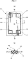
- the method for handling a carrier-film-equipped gasket according to the embodiment is a method intended for handling a carrier-film-equipped gasket 21 illustrated in Fig. 1 and, more specifically, a method for removing a resinous carrier film 41 from a rubber-only type gasket body 31 in a carrier-film-equipped gasket 21 including a combination of the gasket body 31 and the carrier film 41 that retains the gasket body 31.
- the gasket body 31 and the carrier film 41 do not adhere to each other, there are some cases where the gasket body 31 adheres to the carrier film 41 mainly due to the characteristic of the material of the gasket body 31.
- the gasket body 31 is used as, for example, a fuel battery gasket.
- the gasket body 31 is made of a predetermined rubber-like elastic material (e.g. VMQ, PIB, EPDM, and FKM) and formed to have a planar shape (flat plate shape) as a whole.
- An outer peripheral sealing section 32 that seals the entire periphery of the reaction surface of a fuel battery is provided like a planar rectangular frame.
- inner sealing sections (manifold sealing sections) 33 are integrally provided at both ends in the longitudinal direction of the outer peripheral sealing section 32.
- Reference numeral 34 denotes a through hole (void) that passes through the gasket body 31 in the direction of the thickness thereof.
- the cross-sectional shape of the gasket body 31 is rectangular, and a sealing lip 35 having a triangular cross section is formed integrally with the upper surface of the rectangular cross section of the gasket body 31.
- the carrier film 41 is made of a resinous film and has a planar rectangular shape that is slightly larger than the gasket body 31.
- a gasket holding section 42 having a three-dimensional shape to retain the gasket body 31 is provided at a portion which is a part of the plane of the carrier film 41 and which planarly overlaps the gasket body 31.
- a polypropylene film for example, which has a thickness of 0.2 mm, is used, and the polypropylene film is cut to a predetermined planar shape.
- a general resinous material such as polyethylene or polystyrene, can be used in place of polypropylene.
- the thickness of the film is preferably about 0.1 mm to about 0.3 mm, although the thickness depends on the diameter or the cross-sectional shape of the gasket body 31.
- the carrier film 41 is referred to also as the carrier sheet or the gasket holding member.
- the carrier-film-equipped gasket 21 is manufactured as described below.
- a mold rubber forming mold
- injection-molding the rubber-only type gasket body 31 can be used.
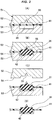
- the planar carrier film 41 which has been cut into a planar shape of a predetermined size, is prepared. Then, the carrier film 41 is held in a parting section 54 of a mold 51 and mold-clamped by the mold 51, as illustrated in Fig. 2(A) .
- the mold 51 is composed of a combination of an upper die (one split die) 52 and a lower die (the other split die) 53, and each of the dies 52 and 53 has a cavity 55 corresponding thereto at the parting section 54.
- the entire surface of the carrier film 41 in its initial state is planar, so that the carrier film 41 is laid across the inside of the cavities 55.
- a molding material for molding the gasket body 31 is charged into the cavities 55 and heated or the like to mold the gasket body 31.
- the molding material is charged in the cavities 55, a part of the plane of the carrier film 41 is pressed against the inner surface of the cavity 55 of the lower die 53 by the molding material charging pressure and deformed (plastically deformed) along the inner surface of the cavity 55, thus molding the gasket holding section 42 having the three-dimensional shape.
- the mold is opened, as illustrated in Fig. 2(C) , and the gasket body 31 and the carrier film 41 are simultaneously taken out of the mold 51, as illustrated in Fig. 2(D) .
- the gasket body 31 and the carrier film 41 which have been taken out, are in a combined state in which the gasket body 31 is retained by the carrier film 41.
- the product is conveyed or stored in the combined state.
- the gasket body 31 retained by the carrier film 41 is resistant to twisting or the like, thus improving the handling property over the case where the gasket body 31 is handled alone.
- the operation for removing the carrier film 41 from the gasket body 31 is performed according to the following procedure.
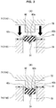
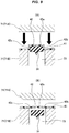
- the carrier-film-equipped gasket 21 is placed on a pressing device 71, and the gasket body 31 is pressed from the carrier film 41 side by using the pressing device 71 thereby to decrease the adhesion area between the gasket body 31 and the carrier film 41, as illustrated in Figs. 3(A) and 3(B) .
- the carrier film 41 has the gasket holding section 42, which has the three-dimensional shape resulting from the deformation along the external shape of the gasket body 31, at the portion that planarly overlaps the gasket body 31, and the carrier film 41 and the gasket body 31 adhere to each other in the state in which a part or all of the gasket body 31 is held in the gasket holding section 42 having the three-dimensional shape.
- the adhesion area between the carrier film 41 and the gasket body 31 is defined by the area of the inner surface of the gasket holding section 42.
- the adhesion area is the sum of the area of a bottom surface 42a of the gasket holding section 42, which bottom surface 42a adheres to the bottom surface of the gasket body 31, the area of one side surface 42b of the gasket holding section 42, which one side surface 42b adheres to a part of one side surface of the gasket body 31, and the area of the other side surface 42c of the gasket holding section 42, which other side surface 42c adheres to a part of the other side surface of the gasket body 31.
- the adhesion area which is the sum of the above areas, is decreased as follows.
- the one side surface 42b of the gasket holding section 42 comes off of the one side surface of the gasket body 31
- the other side surface 42c of the gasket holding section 42 comes off of the other side surface of the gasket body 31
- a part (the portions on both ends in the width direction) of the bottom surface 42a of the gasket holding section 42 comes off of the bottom surface of the gasket body 31, as illustrated in Fig. 3(B) .
- the remaining adhesion section is only a part (a part at the center in the width direction) of the bottom surface 42a of the gasket holding section 42. This completes the preliminary step.
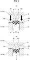
- a pressing constituent element 71A of the pressing device 71 is provided with a pressing projection section 72 for pressing the gasket body 31 from the carrier film 41 side (from the bottom surface 42a side of the gasket holding section 42), and corresponding thereto, a to-be-pressed constituent element 71B of the pressing device 71 is provided with a receiving void 73 for temporarily accommodating the gasket body 31 when displaced by being pressed.
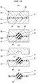
- a width dimension w 1 of the pressing projection section 72 may be set to be equal to or larger than a width dimension w 2 of the gasket body 31, as illustrated in Figs. 4(A) and 4(B) , or the width dimension w 1 may be set to be smaller than the width dimension w 2 of the gasket body 31, as illustrated in Fig. 5(A) and 5(B) .
- the pressing projection section 72 presses only a part (a part at the center in the width direction) of the bottom surface of the gasket body 31, so that the one side surface 42b of the gasket holding section 42 will come off of the gasket body 31, the other side surface 42c of the gasket holding section 42 will come off of the gasket body 31, and a part (the portions at both ends in the width direction) of the bottom surface 42a of the gasket holding section 42 will come off of the gasket body 31, as described above.
- the remaining adhesion part will be only a part (the part at the center in the width direction) of the bottom surface 42a of the gasket holding section 42, so that the adhesion area can be significantly decreased.
- the carrier-film-equipped gasket 21 is placed on a suction section 62 of a vacuuming device 61 serving as a base, the gasket body 31 is fixed (suctioned) by vacuuming (arrow S), and in this state, the carrier film 41 is peeled from the gasket body 31 by using a chucking device (not illustrated) or the like, as illustrated in Figs. 6(A) and 6(B) .
- the carrier film 41 can be removed from the gasket body 31 with a relatively small peeling force and in a short peeling time. Therefore, as intended by the present invention, even if the gasket body 31 is adhered to the carrier film 41, the carrier film 41 can be easily removed, thus enabling the operation for removing the carrier film 41 to be accomplished more easily.
- cross-sectional shape of the carrier-film-equipped gasket 21 including the combination of the rubber-only type gasket body 31 and the resinous carrier film 41, and the cross-sectional shape is not limited to the one illustrated in Fig. 1(B) described above.
- a sealing lip 35 is formed integrally with the bottom surface rather than the top surface of the gasket body 31 having a rectangular cross section. Accordingly, the shape of the gasket holding section 42 having a three-dimensional shape in the carrier film 41 has been changed.
- the present invention also includes a case where the carrier film 41 is used in the planar shape without the gasket holding section 42, which has a three-dimensional shape, as illustrated in Fig. 7(B) .
- the adhesion area between the carrier film 41 and the gasket body 31 is defined by the area of the bottom surface of the gasket body 31. Therefore, when the preliminary step described above is carried out, the adhesion area defined by the area of the bottom surface of the gasket body 31 decreases.
- the carrier film 41 is peeled off at both ends in the width direction of the bottom surface of the gasket body 31.
- the pressing projection section 72 provided on the pressing constituent element 71A of the pressing device 71 may be configured as described below.
- the pressing projection section 72 is provided over the full length in the longitudinal direction of the gasket body 31 to press the gasket body 31 by the full length in the longitudinal direction thereof.
- the pressing projection section 72 may be configured to have a plurality of projections arranged with intervals provided therebetween along the longitudinal direction of the gasket body 31, thus providing non-pressing portions which are formed by voids between the projections that are adjacent to each other and which do not press the gasket body 31.
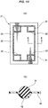
- Fig. 8 illustrates an example of the plurality of projections arranged in the case described above.
- the hatched portions in Fig. 8 denote portions 74 where the projections are disposed, and the blank portions in Fig. 8 denote portions 75 where no projections are disposed, thus providing the non-pressing portions.
- both the portions 74 and 75 are alternately arranged along the longitudinal direction of the gasket body 31.
- the pressing projection section 72 presses the gasket body 31 through the intermediary of the carrier film 41, as illustrated in Fig. 4 and Fig. 5 , so that only the pressed portions will remain as the portions where the carrier film 41 and the gasket body 31 adhere to each other.
- the portions 75 which have no projections and provide the non-pressing portions will be the portions where the carrier film 41 and the gasket body 31 are not in the adherent state and are separate from each other since the portions 75 are free of projections, as illustrated in Figs. 9(A) and 9(B) . This permits a significant reduction in the adhesion area that will remain after the preliminary treatment.
- the foregoing preliminary step for reducing the adhesion area between the gasket body 31 and the carrier film 41 and the peeling step for removing the carrier film 41 from the gasket body 31 can be accomplished with higher operation efficiency by successively or simultaneously carrying out these two steps.
- An embodiment in this case will be described below.
- a base body 82 on a stationary side is provided on a base 81, and a recess (cylinder-like recess) 83 is provided in the base body 82 such that the recess 83 is opposed to a pressing projection section 72 of a pressing device 71.
- a slide section (piston-like slide member) 84 on a movable side is slidably installed in the recess 83, and a return spring 85, which returns the slide section 84 to an initial slide position, is provided at the bottom part of the recess 83.
- the slide section 84 is provided with, as an opening section, a gasket body holding section 86 for retaining the gasket body 31 at the slide section 84, and a suction passage 87 for fixing, by suctioning, the gasket body 31 to the gasket body holding section 86 is provided such that the suction passage 87 is in communication with the opening section.
- the suction passage 87 is connected to a suction source, such as a vacuuming pump, which is not illustrated, through a pipe 88.
- the carrier-film-equipped gasket 21 is placed on the base 81 such that the gasket body 31 is positioned at the gasket body holding section 86 of the slide section 84, as illustrated in Fig. 10(A) .
- the suction source is driven to start vacuuming (arrow S) to fix, by suctioning, the gasket body 31 to the gasket body holding section 86 of the slide section 84.
- the gasket body 31 is pressed from the carrier film 41 side by the pressing projection section 72 of the pressing device 71, thereby reducing the adhesion area between the gasket body 31 and the carrier film 41, as illustrated in Fig. 10(B) .
- the slide section 84 is also pressed, causing the slide section 84 to move by sliding against the elasticity of the return spring 85.
- the carrier film 41 is fixed to the pressing device 71, and the pressing device 71 with the carrier film 41 fixed thereto is moved to return (retract). Since the gasket body 31 remains fixed by suction to the base 81, the carrier film 41 is removed from the gasket body 31.
- the gasket body 31 fixed by suction to the base 81 is opposed to a mounting target part 91 of a fuel battery separator or the like, an adhesive agent is applied to the gasket body 31, as necessary, and the gasket body 31 is installed to the mounting target part 91, as illustrated in Fig. 12(A) .
- the base 81 provided with the slide structure having the foregoing configuration enables the preliminary step and the peeling step to be carried out successively or simultaneously, thus making it possible to improve the operation efficiency.
Abstract
Description
- The present invention relates to a gasket associated with a sealing technology and more specifically to a method for handling a carrier-film-equipped gasket to remove a carrier film from a gasket body against an adhesive force in the carrier-film-equipped gasket including a combination of a rubber-only type gasket body and a resinous carrier film that holds the gasket body. The gasket in accordance with the present invention is used, for example, as the gasket for a fuel battery or as a general gasket for other applications.
- Fuel battery gaskets having various configurations are available, including a rubber-only type gasket composed of a discrete gasket made of a rubber-like elastic material (rubber), a separator integrated gasket formed by molding a gasket, which is composed of a rubber-like elastic material, integrally with a separator, and a GDL integrated gasket formed by molding a gasket, which is composed of a rubber-like elastic member, integrally with a GDL (gas diffusion layer).
- Each of these gaskets has a characteristic. However, because of the recent high demand for reduced cost, rubber-only type gaskets, which can satisfy such demand, are becoming a focus of attention.
- A rubber-only type gasket is configured as illustrated in, for example,
Fig. 13 . - More specifically, a
gasket 11, which is shaped like a plane (like a flat plate) as a whole, is provided with an outerperipheral sealing section 12 for sealing the entire periphery of the reaction surface of a fuel battery, the outerperipheral sealing section 12 being shaped like a planar rectangular frame. Further, it is necessary to partition the reaction surface of the fuel battery and each manifold section, so thatinner sealing sections 13 are integrally provided at both ends in the longitudinal direction of the outerperipheral sealing section 12. The cross-sectional shape of thegasket 11 is, for example, circular, as illustrated inFig. 13(B) . - Patent Document 1: Japanese Unexamined Patent Publication No.
2014-60133 Fig. 1 , etc.) - However, the rubber-only type
fuel battery gasket 11 has the following room to be further improved. - Generally, in the
fuel battery gasket 11, the planar external dimensions are set to be large, approximately 400 mm x 300 mm, while the sectional dimension (diameter) is set to be small, approximately 1 mm to a few millimeters. This tends to cause thegasket 11 in a discrete form to be twisted when being carried or stacked, making it difficult to handle the gasket 11 (poor handling property). - The present applicant, therefore, has developed and proposed a carrier-film-equipped
gasket 21 including a combination of a rubber-onlytype gasket body 31 and aresinous carrier film 41 that retains thegasket body 31, as illustrated inFig. 14 . According to the carrier-film-equippedgasket 21, the rubber-onlytype gasket body 31 is retained by thecarrier film 41 that is stronger than thegasket body 31, thus making the carrier-film-equippedgasket 21 resistant to twisting and therefore enabling handling property to be improved. - As with the
gasket 11 illustrated inFig. 13 , thegasket body 31 is shaped like a plane (like a flat plate) as a whole, and is provided with an outerperipheral sealing section 32 which seals the entire periphery of the reaction surface of a fuel battery and which is shaped like a planar rectangular frame. Further,inner sealing sections 33 are integrally provided at both ends in the longitudinal direction of the outerperipheral sealing section 32 in order to partition the reaction surface of a fuel battery and each manifold section. The cross-sectional shape of thegasket body 31 is, for example, circular, as illustrated inFig. 14(B) . Meanwhile, thecarrier film 41 is formed of a resinous film having a planar rectangular shape that is slightly larger than thegasket body 31. Formed on the plane is agasket holding section 42 having a three-dimensional shape for retaining thegasket body 31. - The carrier-film-equipped
gasket 21 is manufactured as described below. For the manufacture, a mold for injection-molding the rubber-onlytype gasket body 31 can be used. - In the process, first, the
planar carrier film 41, which has been cut into a planar shape of a predetermined size, is prepared. Then, thecarrier film 41 is held in aparting section 54 of amold 51 and mold-clamped by themold 51, as illustrated inFig. 15(A) . Themold 51 is composed of a combination of an upper die (one split die) 52 and a lower die (the other split die) 53, and each of thedies cavity 55 corresponding thereto at theparting section 54. The entire surface of thecarrier film 41 in its initial state is planar, so that thecarrier film 41 is laid across thecavities 55. - Subsequently, as illustrated in
Fig. 15(B) , a molding material for molding thegasket body 31 is charged into thecavities 55 and heated or the like to mold thegasket body 31. When the molding material is charged in thecavities 55, a part of the plane of thecarrier film 41 is pressed against the inner surface of thecavity 55 of thelower die 53 by the molding material charging pressure and deformed (plastically deformed) along the inner surface of thecavity 55, thus molding thegasket holding section 42 having the three-dimensional shape. - Subsequently, after molding the
gasket body 31, the mold is opened, as illustrated inFig. 15(C) , and thegasket body 31 and thecarrier film 41 are simultaneously taken out of themold 51, as illustrated inFig. 15(D) . Thegasket body 31 and thecarrier film 41, which have been taken out, are in a combined state in which thegasket body 31 is retained by thecarrier film 41. The product is conveyed or stored in the combined state. Thegasket body 31 retained by thecarrier film 41 is resistant to twisting or the like, thus improving the handling property over the case where thegasket body 31 is handled alone. - When installing the
gasket body 31 to a fuel battery stack, thecarrier film 41 is removed from thegasket body 31 and only thegasket body 31 is installed to the fuel battery stack. - The
carrier film 41 is removed from thegasket body 31 as illustrated in, for example,Figs. 16(A) and 16(B) . Thegasket body 31 is placed on asuction section 62 of avacuuming device 61 serving as a base, and thegasket body 31 is fixed (suctioned) by vacuuming (arrow S). In this state, thecarrier film 41 is removed from thegasket body 31. At this time, thecarrier film 41, which does not adhere to thegasket body 31, should be easily removed. However, if thegasket body 31 has an adhesive property on its surface mainly due to the characteristic of the material of thegasket body 31 and adheres to thecarrier film 41, then thecarrier film 41 has to be strongly pulled off from thegasket body 31, making the removal difficult. - In view of the aspects described above, an object of the present invention is to provide a method for handling a carrier-film-equipped gasket that enables a carrier film to be easily removed even if a gasket body is adhered to the carrier film when the carrier film is removed from the gasket body in the carrier-film-equipped gasket including a combination of a rubber-only type gasket body and a resinous carrier film that retains the gasket body.
- To this end, a method for handling a gasket in accordance with the present invention is a method for removing a resinous carrier film from a rubber-only type gasket body in a carrier-film-equipped gasket including a combination of the gasket body and the carrier film that retains the gasket body. According to the method, a step of peeling the carrier film from the gasket body against an adhesive force in a state in which the gasket body is fixed to a base is carried out, the gasket body is pressed from a carrier film side by using a pressing device thereby to decrease an adhesion area between the gasket body and the carrier film as a preliminary step of the peeling step, and the peeling step is carried out in a state in which the adhesion area has been decreased.
- In the handling method according to the present invention that has the foregoing configuration, the step of peeling a carrier film from a gasket body against an adhesive force in a state in which the gasket body is fixed to a base is carried out, and the adhesion area between the gasket body and the carrier film is decreased according to a predetermined procedure as a preliminary step (pretreatment step). Hence, the peel force can be decreased by the reduction in the adhesion area, thus making the removing operation easier.
- If a gasket holding section having a three-dimensional shape that has been deformed along the external shape of the gasket body is provided at a portion where the carrier film planarly overlaps the gasket body, then the carrier film and the gasket body adhere to each other in a state in which a part or all of the gasket body is placed in the gasket holding section, so that the size of the adhesion area is defined by the area of the inner surface of the gasket holding section. In this case, therefore, the adhesion area that is defined by the area of the inner surface of the gasket holding section is decreased in the preliminary step.
- A pressing device having a pressing projection section that presses the gasket body from the carrier film side is ideally used as the pressing device used in the preliminary step of the peeling step. In particular, setting the width dimension of the pressing projection section to be smaller than the width dimension of the gasket body causes the peeling to extend to both sides of the pressing projection section, so that the peeling area increases, thus making it possible to further decrease the adhesion area.
- Further, in the pressing projection section, a plurality of projections may be arranged with intervals provided therebetween along the longitudinal direction of the gasket body. In this case, the void between projections that are adjacent to each other will be a non-pressing portion that does not press the gasket body, and the carrier film will be in a state of being separate from the gasket body at the non-pressing portion. This mode, therefore, will also increase the peeling area, thus making it possible to further decrease the adhesion area.
- The preliminary step and the peeling step described above are efficiently performed if carried out successively or simultaneously. For this purpose, a base body, a slide that relatively moves with respect to the base body, a gasket body holding section provided on the slide, and a suction passage provided such that the suction passage opens to the gasket body holding section are placed on a base.
- The present invention makes it possible to easily remove a carrier film even if a gasket body is adhered to the carrier film when the carrier film is removed from the gasket body in a carrier-film-equipped gasket including a combination of a rubber-only type gasket body and a resinous carrier film that retains the gasket body. Hence, the operation for removing the carrier film can be made easier, thus enabling the handling property for the carrier-film-equipped gasket to be improved.
-
-
Fig. 1 illustrates an example of a carrier-film-equipped gasket to be handled by the handling method according to an embodiment of the present invention,Fig. 1(A) being a plan view thereof, andFig. 1(B) being a sectional view of an essential section thereof and an enlarged sectional view taken on line C-C inFig. 1(A) ; -
Figs. 2(A) to 2(D) are explanatory diagrams illustrating the manufacturing process of the gasket; -
Figs. 3(A) and 3(B) are explanatory diagrams illustrating a preliminary step; -
Figs. 4(A) and 4(B) are explanatory diagrams illustrating the preliminary step and the width dimension of a pressing projection section; -
Figs. 5(A) and 5(B) are explanatory diagrams illustrating the preliminary step and the width dimension of the pressing projection section; -
Figs. 6(A) and 6(B) are explanatory diagrams illustrating a peeling step; -
Figs. 7(A) and 7(B) are sectional views of an essential section, illustrating another example of the gasket; -
Fig. 8 is an explanatory diagram illustrating the planar placement of pressing projections; -
Figs. 9(A) and 9(B) are explanatory diagrams of a preliminary step, and are explanatory diagrams which are taken on line F-F inFig. 8 and which illustrate the preliminary step being carried out; -
Figs. 10(A) and 10(B) are explanatory diagrams illustrating a preliminary step according to another embodiment of the present invention; -
Figs. 11(A) and 11(B) are explanatory diagrams illustrating a peeling step according to another embodiment of the present invention; -
Figs. 12(A) and 12(B) are explanatory diagrams illustrating a gasket body installing step according to another embodiment of the present invention; -
Fig. 13 presents diagrams illustrating a rubber-only type gasket according to a conventional example,Fig. 13(A) being a plan view thereof, andFig. 13(B) being an enlarged sectional view of an essential section thereof taken on line D-D inFig. 13(A) ; -
Fig. 14 presents diagrams illustrating a carrier-film-equipped gasket according to a reference example,Fig. 14(A) being a plan view thereof, andFig. 14(B) being an enlarged sectional view of an essential section thereof taken on line E-E inFig. 14(A) ; -
Figs. 15(A) to (D) are explanatory diagrams illustrating the manufacturing process of the gasket; and -
Figs. 16(A) and 16(B) are explanatory diagrams illustrating a peeling step. - The following will describe an embodiment of the present invention with reference to the accompanying drawings.
- The method for handling a carrier-film-equipped gasket according to the embodiment is a method intended for handling a carrier-film-equipped
gasket 21 illustrated inFig. 1 and, more specifically, a method for removing aresinous carrier film 41 from a rubber-onlytype gasket body 31 in a carrier-film-equippedgasket 21 including a combination of thegasket body 31 and thecarrier film 41 that retains thegasket body 31. Although thegasket body 31 and thecarrier film 41 do not adhere to each other, there are some cases where thegasket body 31 adheres to thecarrier film 41 mainly due to the characteristic of the material of thegasket body 31. Thegasket body 31 is used as, for example, a fuel battery gasket. - The
gasket body 31 is made of a predetermined rubber-like elastic material (e.g. VMQ, PIB, EPDM, and FKM) and formed to have a planar shape (flat plate shape) as a whole. An outerperipheral sealing section 32 that seals the entire periphery of the reaction surface of a fuel battery is provided like a planar rectangular frame. Further, in order to partition the reaction surface of the fuel battery and each manifold section, inner sealing sections (manifold sealing sections) 33 are integrally provided at both ends in the longitudinal direction of the outerperipheral sealing section 32.Reference numeral 34 denotes a through hole (void) that passes through thegasket body 31 in the direction of the thickness thereof. As illustrated inFig. 1(B) , the cross-sectional shape of thegasket body 31 is rectangular, and a sealinglip 35 having a triangular cross section is formed integrally with the upper surface of the rectangular cross section of thegasket body 31. - The
carrier film 41 is made of a resinous film and has a planar rectangular shape that is slightly larger than thegasket body 31. Agasket holding section 42 having a three-dimensional shape to retain thegasket body 31 is provided at a portion which is a part of the plane of thecarrier film 41 and which planarly overlaps thegasket body 31. As the resinous film, a polypropylene film, for example, which has a thickness of 0.2 mm, is used, and the polypropylene film is cut to a predetermined planar shape. As the resinous film, a general resinous material, such as polyethylene or polystyrene, can be used in place of polypropylene. The thickness of the film is preferably about 0.1 mm to about 0.3 mm, although the thickness depends on the diameter or the cross-sectional shape of thegasket body 31. Thecarrier film 41 is referred to also as the carrier sheet or the gasket holding member. - The carrier-film-equipped
gasket 21 is manufactured as described below. For the manufacture, a mold (rubber forming mold) for injection-molding the rubber-onlytype gasket body 31 can be used. - In the process, first, the
planar carrier film 41, which has been cut into a planar shape of a predetermined size, is prepared. Then, thecarrier film 41 is held in aparting section 54 of amold 51 and mold-clamped by themold 51, as illustrated inFig. 2(A) . Themold 51 is composed of a combination of an upper die (one split die) 52 and a lower die (the other split die) 53, and each of the dies 52 and 53 has acavity 55 corresponding thereto at theparting section 54. The entire surface of thecarrier film 41 in its initial state is planar, so that thecarrier film 41 is laid across the inside of thecavities 55. - Subsequently, as illustrated in
Fig. 2(B) , a molding material for molding thegasket body 31 is charged into thecavities 55 and heated or the like to mold thegasket body 31. When the molding material is charged in thecavities 55, a part of the plane of thecarrier film 41 is pressed against the inner surface of thecavity 55 of thelower die 53 by the molding material charging pressure and deformed (plastically deformed) along the inner surface of thecavity 55, thus molding thegasket holding section 42 having the three-dimensional shape. - Subsequently, after molding the
gasket body 31, the mold is opened, as illustrated inFig. 2(C) , and thegasket body 31 and thecarrier film 41 are simultaneously taken out of themold 51, as illustrated inFig. 2(D) . Thegasket body 31 and thecarrier film 41, which have been taken out, are in a combined state in which thegasket body 31 is retained by thecarrier film 41. The product is conveyed or stored in the combined state. Thegasket body 31 retained by thecarrier film 41 is resistant to twisting or the like, thus improving the handling property over the case where thegasket body 31 is handled alone. - Although the
gasket body 31 and thecarrier film 41 are not supposed to adhere to each other, there are cases where the surface of thegasket body 31 becomes adhesive due to the characteristic of the material of thegasket body 31 or due to need in molding by themold 51, and the adhesion inconveniently causes thegasket body 31 to adhere to thecarrier film 41. According to the present embodiment, therefore, the operation for removing thecarrier film 41 from thegasket body 31 is performed according to the following procedure. - First, as a preliminary step (pretreatment step), the carrier-film-equipped
gasket 21 is placed on apressing device 71, and thegasket body 31 is pressed from thecarrier film 41 side by using thepressing device 71 thereby to decrease the adhesion area between thegasket body 31 and thecarrier film 41, as illustrated inFigs. 3(A) and 3(B) . - More specifically, as described above, the
carrier film 41 has thegasket holding section 42, which has the three-dimensional shape resulting from the deformation along the external shape of thegasket body 31, at the portion that planarly overlaps thegasket body 31, and thecarrier film 41 and thegasket body 31 adhere to each other in the state in which a part or all of thegasket body 31 is held in thegasket holding section 42 having the three-dimensional shape. Hence, the adhesion area between thecarrier film 41 and thegasket body 31 is defined by the area of the inner surface of thegasket holding section 42. - More specifically, since the
gasket body 31 has the rectangular cross section, the adhesion area is the sum of the area of abottom surface 42a of thegasket holding section 42, whichbottom surface 42a adheres to the bottom surface of thegasket body 31, the area of oneside surface 42b of thegasket holding section 42, which oneside surface 42b adheres to a part of one side surface of thegasket body 31, and the area of theother side surface 42c of thegasket holding section 42, whichother side surface 42c adheres to a part of the other side surface of thegasket body 31. The adhesion area, which is the sum of the above areas, is decreased as follows. As described above, when thegasket body 31 is pressed from thecarrier film 41 side by thepressing device 71, the oneside surface 42b of thegasket holding section 42 comes off of the one side surface of thegasket body 31, theother side surface 42c of thegasket holding section 42 comes off of the other side surface of thegasket body 31, and a part (the portions on both ends in the width direction) of thebottom surface 42a of thegasket holding section 42 comes off of the bottom surface of thegasket body 31, as illustrated inFig. 3(B) . As a result, the remaining adhesion section is only a part (a part at the center in the width direction) of thebottom surface 42a of thegasket holding section 42. This completes the preliminary step. - To carry out the preliminary step, a pressing
constituent element 71A of thepressing device 71 is provided with apressing projection section 72 for pressing thegasket body 31 from thecarrier film 41 side (from thebottom surface 42a side of the gasket holding section 42), and corresponding thereto, a to-be-pressedconstituent element 71B of thepressing device 71 is provided with a receivingvoid 73 for temporarily accommodating thegasket body 31 when displaced by being pressed. - A width dimension w1 of the
pressing projection section 72 may be set to be equal to or larger than a width dimension w2 of thegasket body 31, as illustrated inFigs. 4(A) and 4(B) , or the width dimension w1 may be set to be smaller than the width dimension w2 of thegasket body 31, as illustrated inFig. 5(A) and 5(B) . In the latter case, thepressing projection section 72 presses only a part (a part at the center in the width direction) of the bottom surface of thegasket body 31, so that the oneside surface 42b of thegasket holding section 42 will come off of thegasket body 31, theother side surface 42c of thegasket holding section 42 will come off of thegasket body 31, and a part (the portions at both ends in the width direction) of thebottom surface 42a of thegasket holding section 42 will come off of thegasket body 31, as described above. Thus, the remaining adhesion part will be only a part (the part at the center in the width direction) of thebottom surface 42a of thegasket holding section 42, so that the adhesion area can be significantly decreased. - Subsequently, following the foregoing preliminary step, the carrier-film-equipped
gasket 21 is placed on asuction section 62 of avacuuming device 61 serving as a base, thegasket body 31 is fixed (suctioned) by vacuuming (arrow S), and in this state, thecarrier film 41 is peeled from thegasket body 31 by using a chucking device (not illustrated) or the like, as illustrated inFigs. 6(A) and 6(B) . At this time, since the adhesion area between thecarrier film 41 and thegasket body 31 has already been decreased in the preliminary step, thecarrier film 41 can be removed from thegasket body 31 with a relatively small peeling force and in a short peeling time. Therefore, as intended by the present invention, even if thegasket body 31 is adhered to thecarrier film 41, thecarrier film 41 can be easily removed, thus enabling the operation for removing thecarrier film 41 to be accomplished more easily. - Various cross-sectional shapes are conceivable as the cross-sectional shape of the carrier-film-equipped
gasket 21 including the combination of the rubber-onlytype gasket body 31 and theresinous carrier film 41, and the cross-sectional shape is not limited to the one illustrated inFig. 1(B) described above. - For example, in the example illustrated in
Fig. 7(A) , a sealinglip 35 is formed integrally with the bottom surface rather than the top surface of thegasket body 31 having a rectangular cross section. Accordingly, the shape of thegasket holding section 42 having a three-dimensional shape in thecarrier film 41 has been changed. - Further, the present invention also includes a case where the
carrier film 41 is used in the planar shape without thegasket holding section 42, which has a three-dimensional shape, as illustrated inFig. 7(B) . In this case, the adhesion area between thecarrier film 41 and thegasket body 31 is defined by the area of the bottom surface of thegasket body 31. Therefore, when the preliminary step described above is carried out, the adhesion area defined by the area of the bottom surface of thegasket body 31 decreases. To be specific, thecarrier film 41 is peeled off at both ends in the width direction of the bottom surface of thegasket body 31. - Further, in order to decrease the adhesion area by carrying out the foregoing preliminary step, the
pressing projection section 72 provided on the pressingconstituent element 71A of thepressing device 71 may be configured as described below. - In the foregoing embodiment, the
pressing projection section 72 is provided over the full length in the longitudinal direction of thegasket body 31 to press thegasket body 31 by the full length in the longitudinal direction thereof. Instead, thepressing projection section 72 may be configured to have a plurality of projections arranged with intervals provided therebetween along the longitudinal direction of thegasket body 31, thus providing non-pressing portions which are formed by voids between the projections that are adjacent to each other and which do not press thegasket body 31. -
Fig. 8 illustrates an example of the plurality of projections arranged in the case described above. The hatched portions inFig. 8 denote portions 74 where the projections are disposed, and the blank portions inFig. 8 denote portions 75 where no projections are disposed, thus providing the non-pressing portions. As illustrated, both theportions gasket body 31. - According to this configuration, at the
portions 74 where the projections are disposed, thepressing projection section 72 presses thegasket body 31 through the intermediary of thecarrier film 41, as illustrated inFig. 4 andFig. 5 , so that only the pressed portions will remain as the portions where thecarrier film 41 and thegasket body 31 adhere to each other. Meanwhile, theportions 75 which have no projections and provide the non-pressing portions will be the portions where thecarrier film 41 and thegasket body 31 are not in the adherent state and are separate from each other since theportions 75 are free of projections, as illustrated inFigs. 9(A) and 9(B) . This permits a significant reduction in the adhesion area that will remain after the preliminary treatment. - The foregoing preliminary step for reducing the adhesion area between the
gasket body 31 and thecarrier film 41 and the peeling step for removing thecarrier film 41 from thegasket body 31 can be accomplished with higher operation efficiency by successively or simultaneously carrying out these two steps. An embodiment in this case will be described below. - As illustrated in
Fig. 10(A) , abase body 82 on a stationary side is provided on abase 81, and a recess (cylinder-like recess) 83 is provided in thebase body 82 such that therecess 83 is opposed to apressing projection section 72 of apressing device 71. A slide section (piston-like slide member) 84 on a movable side is slidably installed in therecess 83, and areturn spring 85, which returns theslide section 84 to an initial slide position, is provided at the bottom part of therecess 83. - The
slide section 84 is provided with, as an opening section, a gasketbody holding section 86 for retaining thegasket body 31 at theslide section 84, and asuction passage 87 for fixing, by suctioning, thegasket body 31 to the gasketbody holding section 86 is provided such that thesuction passage 87 is in communication with the opening section. Thesuction passage 87 is connected to a suction source, such as a vacuuming pump, which is not illustrated, through apipe 88. - To start the preliminary step, the carrier-film-equipped
gasket 21 is placed on the base 81 such that thegasket body 31 is positioned at the gasketbody holding section 86 of theslide section 84, as illustrated inFig. 10(A) . - Subsequently, the suction source is driven to start vacuuming (arrow S) to fix, by suctioning, the
gasket body 31 to the gasketbody holding section 86 of theslide section 84. In this suction-fixed state, thegasket body 31 is pressed from thecarrier film 41 side by thepressing projection section 72 of thepressing device 71, thereby reducing the adhesion area between thegasket body 31 and thecarrier film 41, as illustrated inFig. 10(B) . When thegasket body 31 is pressed from thecarrier film 41 side by thepressing projection section 72 of thepressing device 71, theslide section 84 is also pressed, causing theslide section 84 to move by sliding against the elasticity of thereturn spring 85. - Subsequently, as illustrated in
Fig. 11(A) , thecarrier film 41 is fixed to thepressing device 71, and thepressing device 71 with thecarrier film 41 fixed thereto is moved to return (retract). Since thegasket body 31 remains fixed by suction to thebase 81, thecarrier film 41 is removed from thegasket body 31. - Subsequently, as illustrated in
Fig. 11(B) , thegasket body 31 fixed by suction to thebase 81 is opposed to a mountingtarget part 91 of a fuel battery separator or the like, an adhesive agent is applied to thegasket body 31, as necessary, and thegasket body 31 is installed to the mountingtarget part 91, as illustrated inFig. 12(A) . This completes the mounting step, as illustrated inFig. 12(B) . - Accordingly, using the
base 81 provided with the slide structure having the foregoing configuration enables the preliminary step and the peeling step to be carried out successively or simultaneously, thus making it possible to improve the operation efficiency. -
- 21
- carrier-film-equipped gasket
- 31
- gasket body
- 32
- outer peripheral sealing section
- 33
- inner sealing section
- 34
- through hole
- 35
- sealing lip
- 41
- carrier film
- 42
- gasket holding section
- 42a
- bottom surface
- 42b, 42c
- side surface
- 51
- mold
- 52
- upper die
- 53
- lower die
- 54
- parting section
- 55
- cavity
- 61
- vacuuming device
- 62
- suction section
- 71
- pressing device
- 71A
- pressing constituent element
- 71B
- to-be-pressed constituent element
- 72
- pressing projection section
- 73
- receiving void
- 74
- portion where a projection is disposed
- 75
- portion where no projections are disposed, thus providing a non-pressing portion
- 81
- base
- 82
- base body
- 83
- recess
- 84
- slide section
- 85
- return spring
- 86
- gasket body holding section
- 87
- suction passage
- 88
- pipe
- 91
- mounting target part
Claims (6)
- A method for handling a carrier-film-equipped gasket, which is a method for removing a resinous carrier film from a rubber-only type gasket body in a carrier-film-equipped gasket including a combination of the gasket body and the carrier film, which retains the gasket body,
the method comprising:a peeling step of peeling the carrier film from the gasket body against an adhesive force in a state in which the gasket body is fixed to a base, anda step of decreasing an adhesion area between the gasket body and the carrier film by pressing the gasket body from a carrier film side by using a pressing device, the step of decreasing an adhesion area being preliminary to the peeling step,wherein the peeling step is carried out in the state in which the adhesion area has been decreased. - The method for handling a carrier-film-equipped gasket according to claim 1,
wherein the carrier film includes, in a portion that planarly overlaps the gasket body, a gasket holding section having a three-dimensional shape that has been deformed along an external shape of the gasket body,
the carrier film and the gasket body adhere to each other in a state in which a part or all of the gasket body is placed in the gasket holding section, the adhesion area being defined by the area of an inner surface of the gasket holding section, and
the preliminary step is carried out to decrease the adhesion area defined by the area of the inner surface of the gasket holding section. - The method for handling a carrier-film-equipped gasket according to claim 1 or 2,
wherein the pressing device has a pressing projection section that presses the gasket body from the carrier film side, and
a width dimension of the pressing projection section is set to be smaller than a width dimension of the gasket body. - The method for handling a carrier-film-equipped gasket according to claim 1, 2 or 3,
wherein the pressing device has a pressing projection section that presses the gasket body from the carrier film side, and
the pressing projection section has a plurality of projections arranged with intervals provided therebetween along a longitudinal direction of the gasket body, and voids between the projections form non-pressing portions which do not press the gasket body. - The method for handling a carrier-film-equipped gasket according to claim 1, 2, 3 or 4,
wherein the preliminary step and the peeling step are successively or simultaneously carried out. - The method for handling a carrier-film-equipped gasket according to claim 5,
wherein, in order to successively or simultaneously carry out the preliminary step and the peeling step, the base has a base body, a slide that relatively moves with respect to the base body, a gasket body holding section provided at the slide, and a suction passage provided such that the suction passage opens to the gasket body holding section.
Applications Claiming Priority (4)
| Application Number | Priority Date | Filing Date | Title |
|---|---|---|---|
| JP2015220279 | 2015-11-10 | ||
| JP2015238295 | 2015-12-07 | ||
| JP2016151710A JP6795349B2 (en) | 2015-11-10 | 2016-08-02 | How to handle gaskets with carrier film |
| PCT/JP2016/082737 WO2017082154A1 (en) | 2015-11-10 | 2016-11-04 | Method for handling carrier-film-equipped gasket |
Publications (3)
| Publication Number | Publication Date |
|---|---|
| EP3376577A1 true EP3376577A1 (en) | 2018-09-19 |
| EP3376577A4 EP3376577A4 (en) | 2018-11-14 |
| EP3376577B1 EP3376577B1 (en) | 2021-03-24 |
Family
ID=59059551
Family Applications (1)
| Application Number | Title | Priority Date | Filing Date |
|---|---|---|---|
| EP16864117.3A Active EP3376577B1 (en) | 2015-11-10 | 2016-11-04 | Method for handling carrier-film-equipped gasket |
Country Status (6)
| Country | Link |
|---|---|
| US (1) | US10514099B2 (en) |
| EP (1) | EP3376577B1 (en) |
| JP (1) | JP6795349B2 (en) |
| KR (1) | KR102617254B1 (en) |
| CN (1) | CN108028398B (en) |
| CA (1) | CA3004691C (en) |
Families Citing this family (4)
| Publication number | Priority date | Publication date | Assignee | Title |
|---|---|---|---|---|
| US10513066B2 (en) * | 2015-04-24 | 2019-12-24 | Nok Corporation | Gasket molded product and method of manufacturing the same |
| CN107532718B (en) * | 2015-06-04 | 2019-09-13 | Nok株式会社 | Gasket and its manufacturing method |
| JP6673678B2 (en) * | 2015-12-03 | 2020-03-25 | Nok株式会社 | Gasket with carrier film and method of manufacturing the same |
| KR20200012865A (en) * | 2017-05-30 | 2020-02-05 | 엔오케이 가부시키가이샤 | Handling of Gasket with Carrier Film |
Family Cites Families (16)
| Publication number | Priority date | Publication date | Assignee | Title |
|---|---|---|---|---|
| IT1182305B (en) * | 1984-10-01 | 1987-10-05 | Tako Spa | MANUFACTURING PROCESS OF SEALING AND PRODUCT GASKETS OBTAINED WITH THE PROCEDURE |
| DE4243989C2 (en) * | 1992-12-23 | 1996-08-29 | Bayerische Motoren Werke Ag | Hand-held device for attaching a self-adhesive seal |
| US5564714A (en) * | 1993-02-23 | 1996-10-15 | Three Bond Co., Ltd. | Rubber-like molded product with support frame |
| JPH06246848A (en) * | 1993-02-23 | 1994-09-06 | Three Bond Co Ltd | Rubber-like molded piece with support frame, its production, and loading method for rubber-like molded piece |
| US5536342A (en) * | 1994-03-18 | 1996-07-16 | W. L. Gore & Associates, Inc. | Automated gasket applicator and method of using same |
| JP2002147610A (en) * | 2000-11-14 | 2002-05-22 | Mitsubishi Plastics Ind Ltd | Packing with support base and method of manufacturing the same |
| FR2832482B1 (en) | 2001-11-21 | 2004-07-02 | Saint Gobain Performance Plast | METHOD FOR MANUFACTURING A COMPOSITE SEAL CORD |
| WO2006006542A1 (en) * | 2004-07-08 | 2006-01-19 | Nhk Spring Co., Ltd. | Gasket, method of producing the gasket, and gasket installation method |
| JP4527513B2 (en) | 2004-12-10 | 2010-08-18 | 株式会社日立製作所 | Fuel cell stack stacker |
| US8012284B2 (en) * | 2006-12-15 | 2011-09-06 | 3M Innovative Properties Company | Method and apparatus for fabricating roll good fuel cell subassemblies |
| KR101449124B1 (en) | 2012-09-17 | 2014-10-08 | 현대자동차주식회사 | An integrated fluorine gasket manufactured by injection molding for hydrogen fuel cells |
| KR101961369B1 (en) | 2012-11-09 | 2019-03-22 | 엘지전자 주식회사 | Mobile terminal and method for operating the same |
| JP2015097195A (en) * | 2013-10-09 | 2015-05-21 | 日東電工株式会社 | Method for manufacturing fuel cell membrane/electrode assembly |
| WO2016163158A1 (en) | 2015-04-09 | 2016-10-13 | Nok株式会社 | Gasket and manufacturing method for same |
| JP6495106B2 (en) * | 2015-06-04 | 2019-04-03 | Nok株式会社 | Gasket and manufacturing method thereof |
| CN106916282B (en) * | 2015-12-28 | 2019-07-26 | 广东生益科技股份有限公司 | A kind of composition epoxy resin and prepreg and laminate using it |
-
2016
- 2016-08-02 JP JP2016151710A patent/JP6795349B2/en active Active
- 2016-11-04 CA CA3004691A patent/CA3004691C/en active Active
- 2016-11-04 CN CN201680053443.4A patent/CN108028398B/en active Active
- 2016-11-04 US US15/770,945 patent/US10514099B2/en active Active
- 2016-11-04 KR KR1020187016059A patent/KR102617254B1/en active IP Right Grant
- 2016-11-04 EP EP16864117.3A patent/EP3376577B1/en active Active
Also Published As
| Publication number | Publication date |
|---|---|
| JP2017106615A (en) | 2017-06-15 |
| CA3004691A1 (en) | 2017-05-18 |
| EP3376577A4 (en) | 2018-11-14 |
| KR102617254B1 (en) | 2023-12-21 |
| JP6795349B2 (en) | 2020-12-02 |
| US10514099B2 (en) | 2019-12-24 |
| CA3004691C (en) | 2023-08-08 |
| US20180313448A1 (en) | 2018-11-01 |
| KR20180084070A (en) | 2018-07-24 |
| CN108028398A (en) | 2018-05-11 |
| EP3376577B1 (en) | 2021-03-24 |
| CN108028398B (en) | 2020-11-27 |
Similar Documents
| Publication | Publication Date | Title |
|---|---|---|
| EP3376577B1 (en) | Method for handling carrier-film-equipped gasket | |
| KR102493194B1 (en) | Gasket molded article and its manufacturing method | |
| EP3534045B1 (en) | Gasket and method for manufacturing same | |
| EP3168022A1 (en) | Production method for plate-integrated gasket | |
| CN108368937B (en) | Gasket and method of making and operating same | |
| EP3633242A1 (en) | Method for handling gasket having carrier film | |
| EP3457003B1 (en) | Gasket and method for mounting same | |
| EP3385575B1 (en) | Gasket and manufacturing method therefor | |
| WO2017082154A1 (en) | Method for handling carrier-film-equipped gasket | |
| EP3467355B1 (en) | Gasket handling method |
Legal Events
| Date | Code | Title | Description |
|---|---|---|---|
| STAA | Information on the status of an ep patent application or granted ep patent |
Free format text: STATUS: THE INTERNATIONAL PUBLICATION HAS BEEN MADE |
|
| PUAI | Public reference made under article 153(3) epc to a published international application that has entered the european phase |
Free format text: ORIGINAL CODE: 0009012 |
|
| STAA | Information on the status of an ep patent application or granted ep patent |
Free format text: STATUS: REQUEST FOR EXAMINATION WAS MADE |
|
| 17P | Request for examination filed |
Effective date: 20180523 |
|
| AK | Designated contracting states |
Kind code of ref document: A1 Designated state(s): AL AT BE BG CH CY CZ DE DK EE ES FI FR GB GR HR HU IE IS IT LI LT LU LV MC MK MT NL NO PL PT RO RS SE SI SK SM TR |
|
| AX | Request for extension of the european patent |
Extension state: BA ME |
|
| A4 | Supplementary search report drawn up and despatched |
Effective date: 20181012 |
|
| RIC1 | Information provided on ipc code assigned before grant |
Ipc: H01M 8/0271 20160101AFI20181008BHEP Ipc: B25B 27/00 20060101ALI20181008BHEP Ipc: F16J 15/10 20060101ALI20181008BHEP |
|
| DAV | Request for validation of the european patent (deleted) | ||
| DAX | Request for extension of the european patent (deleted) | ||
| STAA | Information on the status of an ep patent application or granted ep patent |
Free format text: STATUS: EXAMINATION IS IN PROGRESS |
|
| 17Q | First examination report despatched |
Effective date: 20191217 |
|
| GRAP | Despatch of communication of intention to grant a patent |
Free format text: ORIGINAL CODE: EPIDOSNIGR1 |
|
| STAA | Information on the status of an ep patent application or granted ep patent |
Free format text: STATUS: GRANT OF PATENT IS INTENDED |
|
| INTG | Intention to grant announced |
Effective date: 20201005 |
|
| GRAJ | Information related to disapproval of communication of intention to grant by the applicant or resumption of examination proceedings by the epo deleted |
Free format text: ORIGINAL CODE: EPIDOSDIGR1 |
|
| STAA | Information on the status of an ep patent application or granted ep patent |
Free format text: STATUS: EXAMINATION IS IN PROGRESS |
|
| GRAS | Grant fee paid |
Free format text: ORIGINAL CODE: EPIDOSNIGR3 |
|
| STAA | Information on the status of an ep patent application or granted ep patent |
Free format text: STATUS: GRANT OF PATENT IS INTENDED |
|
| INTC | Intention to grant announced (deleted) | ||
| GRAP | Despatch of communication of intention to grant a patent |
Free format text: ORIGINAL CODE: EPIDOSNIGR1 |
|
| STAA | Information on the status of an ep patent application or granted ep patent |
Free format text: STATUS: GRANT OF PATENT IS INTENDED |
|
| INTG | Intention to grant announced |
Effective date: 20210119 |
|
| GRAA | (expected) grant |
Free format text: ORIGINAL CODE: 0009210 |
|
| STAA | Information on the status of an ep patent application or granted ep patent |
Free format text: STATUS: THE PATENT HAS BEEN GRANTED |
|
| AK | Designated contracting states |
Kind code of ref document: B1 Designated state(s): AL AT BE BG CH CY CZ DE DK EE ES FI FR GB GR HR HU IE IS IT LI LT LU LV MC MK MT NL NO PL PT RO RS SE SI SK SM TR |
|
| REG | Reference to a national code |
Ref country code: GB Ref legal event code: FG4D |
|
| REG | Reference to a national code |
Ref country code: CH Ref legal event code: EP |
|
| REG | Reference to a national code |
Ref country code: DE Ref legal event code: R096 Ref document number: 602016055006 Country of ref document: DE |
|
| REG | Reference to a national code |
Ref country code: IE Ref legal event code: FG4D |
|
| REG | Reference to a national code |
Ref country code: AT Ref legal event code: REF Ref document number: 1375417 Country of ref document: AT Kind code of ref document: T Effective date: 20210415 |
|
| REG | Reference to a national code |
Ref country code: LT Ref legal event code: MG9D |
|
| PG25 | Lapsed in a contracting state [announced via postgrant information from national office to epo] |
Ref country code: NO Free format text: LAPSE BECAUSE OF FAILURE TO SUBMIT A TRANSLATION OF THE DESCRIPTION OR TO PAY THE FEE WITHIN THE PRESCRIBED TIME-LIMIT Effective date: 20210624 Ref country code: FI Free format text: LAPSE BECAUSE OF FAILURE TO SUBMIT A TRANSLATION OF THE DESCRIPTION OR TO PAY THE FEE WITHIN THE PRESCRIBED TIME-LIMIT Effective date: 20210324 Ref country code: GR Free format text: LAPSE BECAUSE OF FAILURE TO SUBMIT A TRANSLATION OF THE DESCRIPTION OR TO PAY THE FEE WITHIN THE PRESCRIBED TIME-LIMIT Effective date: 20210625 Ref country code: HR Free format text: LAPSE BECAUSE OF FAILURE TO SUBMIT A TRANSLATION OF THE DESCRIPTION OR TO PAY THE FEE WITHIN THE PRESCRIBED TIME-LIMIT Effective date: 20210324 Ref country code: BG Free format text: LAPSE BECAUSE OF FAILURE TO SUBMIT A TRANSLATION OF THE DESCRIPTION OR TO PAY THE FEE WITHIN THE PRESCRIBED TIME-LIMIT Effective date: 20210624 |
|
| PG25 | Lapsed in a contracting state [announced via postgrant information from national office to epo] |
Ref country code: LV Free format text: LAPSE BECAUSE OF FAILURE TO SUBMIT A TRANSLATION OF THE DESCRIPTION OR TO PAY THE FEE WITHIN THE PRESCRIBED TIME-LIMIT Effective date: 20210324 Ref country code: RS Free format text: LAPSE BECAUSE OF FAILURE TO SUBMIT A TRANSLATION OF THE DESCRIPTION OR TO PAY THE FEE WITHIN THE PRESCRIBED TIME-LIMIT Effective date: 20210324 Ref country code: SE Free format text: LAPSE BECAUSE OF FAILURE TO SUBMIT A TRANSLATION OF THE DESCRIPTION OR TO PAY THE FEE WITHIN THE PRESCRIBED TIME-LIMIT Effective date: 20210324 |
|
| REG | Reference to a national code |
Ref country code: NL Ref legal event code: MP Effective date: 20210324 |
|
| REG | Reference to a national code |
Ref country code: AT Ref legal event code: MK05 Ref document number: 1375417 Country of ref document: AT Kind code of ref document: T Effective date: 20210324 |
|
| PG25 | Lapsed in a contracting state [announced via postgrant information from national office to epo] |
Ref country code: NL Free format text: LAPSE BECAUSE OF FAILURE TO SUBMIT A TRANSLATION OF THE DESCRIPTION OR TO PAY THE FEE WITHIN THE PRESCRIBED TIME-LIMIT Effective date: 20210324 |
|
| PG25 | Lapsed in a contracting state [announced via postgrant information from national office to epo] |
Ref country code: EE Free format text: LAPSE BECAUSE OF FAILURE TO SUBMIT A TRANSLATION OF THE DESCRIPTION OR TO PAY THE FEE WITHIN THE PRESCRIBED TIME-LIMIT Effective date: 20210324 Ref country code: CZ Free format text: LAPSE BECAUSE OF FAILURE TO SUBMIT A TRANSLATION OF THE DESCRIPTION OR TO PAY THE FEE WITHIN THE PRESCRIBED TIME-LIMIT Effective date: 20210324 Ref country code: LT Free format text: LAPSE BECAUSE OF FAILURE TO SUBMIT A TRANSLATION OF THE DESCRIPTION OR TO PAY THE FEE WITHIN THE PRESCRIBED TIME-LIMIT Effective date: 20210324 Ref country code: AT Free format text: LAPSE BECAUSE OF FAILURE TO SUBMIT A TRANSLATION OF THE DESCRIPTION OR TO PAY THE FEE WITHIN THE PRESCRIBED TIME-LIMIT Effective date: 20210324 Ref country code: SM Free format text: LAPSE BECAUSE OF FAILURE TO SUBMIT A TRANSLATION OF THE DESCRIPTION OR TO PAY THE FEE WITHIN THE PRESCRIBED TIME-LIMIT Effective date: 20210324 |
|
| PG25 | Lapsed in a contracting state [announced via postgrant information from national office to epo] |
Ref country code: PL Free format text: LAPSE BECAUSE OF FAILURE TO SUBMIT A TRANSLATION OF THE DESCRIPTION OR TO PAY THE FEE WITHIN THE PRESCRIBED TIME-LIMIT Effective date: 20210324 Ref country code: PT Free format text: LAPSE BECAUSE OF FAILURE TO SUBMIT A TRANSLATION OF THE DESCRIPTION OR TO PAY THE FEE WITHIN THE PRESCRIBED TIME-LIMIT Effective date: 20210726 Ref country code: SK Free format text: LAPSE BECAUSE OF FAILURE TO SUBMIT A TRANSLATION OF THE DESCRIPTION OR TO PAY THE FEE WITHIN THE PRESCRIBED TIME-LIMIT Effective date: 20210324 Ref country code: RO Free format text: LAPSE BECAUSE OF FAILURE TO SUBMIT A TRANSLATION OF THE DESCRIPTION OR TO PAY THE FEE WITHIN THE PRESCRIBED TIME-LIMIT Effective date: 20210324 Ref country code: IS Free format text: LAPSE BECAUSE OF FAILURE TO SUBMIT A TRANSLATION OF THE DESCRIPTION OR TO PAY THE FEE WITHIN THE PRESCRIBED TIME-LIMIT Effective date: 20210724 |
|
| REG | Reference to a national code |
Ref country code: DE Ref legal event code: R097 Ref document number: 602016055006 Country of ref document: DE |
|
| PG25 | Lapsed in a contracting state [announced via postgrant information from national office to epo] |
Ref country code: DK Free format text: LAPSE BECAUSE OF FAILURE TO SUBMIT A TRANSLATION OF THE DESCRIPTION OR TO PAY THE FEE WITHIN THE PRESCRIBED TIME-LIMIT Effective date: 20210324 Ref country code: AL Free format text: LAPSE BECAUSE OF FAILURE TO SUBMIT A TRANSLATION OF THE DESCRIPTION OR TO PAY THE FEE WITHIN THE PRESCRIBED TIME-LIMIT Effective date: 20210324 Ref country code: ES Free format text: LAPSE BECAUSE OF FAILURE TO SUBMIT A TRANSLATION OF THE DESCRIPTION OR TO PAY THE FEE WITHIN THE PRESCRIBED TIME-LIMIT Effective date: 20210324 |
|
| PLBE | No opposition filed within time limit |
Free format text: ORIGINAL CODE: 0009261 |
|
| STAA | Information on the status of an ep patent application or granted ep patent |
Free format text: STATUS: NO OPPOSITION FILED WITHIN TIME LIMIT |
|
| PG25 | Lapsed in a contracting state [announced via postgrant information from national office to epo] |
Ref country code: SI Free format text: LAPSE BECAUSE OF FAILURE TO SUBMIT A TRANSLATION OF THE DESCRIPTION OR TO PAY THE FEE WITHIN THE PRESCRIBED TIME-LIMIT Effective date: 20210324 |
|
| 26N | No opposition filed |
Effective date: 20220104 |
|
| PG25 | Lapsed in a contracting state [announced via postgrant information from national office to epo] |
Ref country code: IS Free format text: LAPSE BECAUSE OF FAILURE TO SUBMIT A TRANSLATION OF THE DESCRIPTION OR TO PAY THE FEE WITHIN THE PRESCRIBED TIME-LIMIT Effective date: 20210724 |
|
| PG25 | Lapsed in a contracting state [announced via postgrant information from national office to epo] |
Ref country code: MC Free format text: LAPSE BECAUSE OF FAILURE TO SUBMIT A TRANSLATION OF THE DESCRIPTION OR TO PAY THE FEE WITHIN THE PRESCRIBED TIME-LIMIT Effective date: 20210324 |
|
| REG | Reference to a national code |
Ref country code: CH Ref legal event code: PL |
|
| GBPC | Gb: european patent ceased through non-payment of renewal fee |
Effective date: 20211104 |
|
| PG25 | Lapsed in a contracting state [announced via postgrant information from national office to epo] |
Ref country code: LU Free format text: LAPSE BECAUSE OF NON-PAYMENT OF DUE FEES Effective date: 20211104 Ref country code: BE Free format text: LAPSE BECAUSE OF NON-PAYMENT OF DUE FEES Effective date: 20211130 |
|
| REG | Reference to a national code |
Ref country code: BE Ref legal event code: MM Effective date: 20211130 |
|
| PG25 | Lapsed in a contracting state [announced via postgrant information from national office to epo] |
Ref country code: IE Free format text: LAPSE BECAUSE OF NON-PAYMENT OF DUE FEES Effective date: 20211104 Ref country code: GB Free format text: LAPSE BECAUSE OF NON-PAYMENT OF DUE FEES Effective date: 20211104 |
|
| PG25 | Lapsed in a contracting state [announced via postgrant information from national office to epo] |
Ref country code: FR Free format text: LAPSE BECAUSE OF NON-PAYMENT OF DUE FEES Effective date: 20211130 |
|
| PG25 | Lapsed in a contracting state [announced via postgrant information from national office to epo] |
Ref country code: IT Free format text: LAPSE BECAUSE OF FAILURE TO SUBMIT A TRANSLATION OF THE DESCRIPTION OR TO PAY THE FEE WITHIN THE PRESCRIBED TIME-LIMIT Effective date: 20210324 |
|
| PG25 | Lapsed in a contracting state [announced via postgrant information from national office to epo] |
Ref country code: HU Free format text: LAPSE BECAUSE OF FAILURE TO SUBMIT A TRANSLATION OF THE DESCRIPTION OR TO PAY THE FEE WITHIN THE PRESCRIBED TIME-LIMIT; INVALID AB INITIO Effective date: 20161104 |
|
| PG25 | Lapsed in a contracting state [announced via postgrant information from national office to epo] |
Ref country code: CY Free format text: LAPSE BECAUSE OF FAILURE TO SUBMIT A TRANSLATION OF THE DESCRIPTION OR TO PAY THE FEE WITHIN THE PRESCRIBED TIME-LIMIT Effective date: 20210324 |
|
| PG25 | Lapsed in a contracting state [announced via postgrant information from national office to epo] |
Ref country code: LI Free format text: LAPSE BECAUSE OF NON-PAYMENT OF DUE FEES Effective date: 20220630 Ref country code: CH Free format text: LAPSE BECAUSE OF NON-PAYMENT OF DUE FEES Effective date: 20220630 |
|
| PGFP | Annual fee paid to national office [announced via postgrant information from national office to epo] |
Ref country code: DE Payment date: 20230929 Year of fee payment: 8 |