EP3376563A1 - Separator and battery comprising same - Google Patents
Separator and battery comprising same Download PDFInfo
- Publication number
- EP3376563A1 EP3376563A1 EP16876098.1A EP16876098A EP3376563A1 EP 3376563 A1 EP3376563 A1 EP 3376563A1 EP 16876098 A EP16876098 A EP 16876098A EP 3376563 A1 EP3376563 A1 EP 3376563A1
- Authority
- EP
- European Patent Office
- Prior art keywords
- separator
- bonding layer
- layer pattern
- pattern
- bonding
- Prior art date
- Legal status (The legal status is an assumption and is not a legal conclusion. Google has not performed a legal analysis and makes no representation as to the accuracy of the status listed.)
- Granted
Links
- 239000000758 substrate Substances 0.000 claims abstract description 19
- 238000007646 gravure printing Methods 0.000 claims description 37
- 238000000034 method Methods 0.000 claims description 31
- 239000011230 binding agent Substances 0.000 claims description 18
- 239000000203 mixture Substances 0.000 claims description 17
- 238000005192 partition Methods 0.000 claims description 12
- 239000002904 solvent Substances 0.000 claims description 9
- 239000004094 surface-active agent Substances 0.000 claims description 5
- 239000010410 layer Substances 0.000 description 90
- 230000000052 comparative effect Effects 0.000 description 28
- 238000009736 wetting Methods 0.000 description 24
- 239000008151 electrolyte solution Substances 0.000 description 22
- WHXSMMKQMYFTQS-UHFFFAOYSA-N Lithium Chemical compound [Li] WHXSMMKQMYFTQS-UHFFFAOYSA-N 0.000 description 20
- 229910052744 lithium Inorganic materials 0.000 description 20
- -1 polyethylene Polymers 0.000 description 18
- 239000000243 solution Substances 0.000 description 17
- 239000004698 Polyethylene Substances 0.000 description 15
- 229920000573 polyethylene Polymers 0.000 description 15
- HBBGRARXTFLTSG-UHFFFAOYSA-N Lithium ion Chemical compound [Li+] HBBGRARXTFLTSG-UHFFFAOYSA-N 0.000 description 10
- 229910001416 lithium ion Inorganic materials 0.000 description 10
- 239000000654 additive Substances 0.000 description 8
- 230000000996 additive effect Effects 0.000 description 8
- LFQSCWFLJHTTHZ-UHFFFAOYSA-N Ethanol Chemical compound CCO LFQSCWFLJHTTHZ-UHFFFAOYSA-N 0.000 description 7
- 230000000694 effects Effects 0.000 description 7
- 150000002500 ions Chemical class 0.000 description 7
- 238000007639 printing Methods 0.000 description 7
- CSCPPACGZOOCGX-UHFFFAOYSA-N Acetone Chemical compound CC(C)=O CSCPPACGZOOCGX-UHFFFAOYSA-N 0.000 description 6
- OKKJLVBELUTLKV-UHFFFAOYSA-N Methanol Chemical compound OC OKKJLVBELUTLKV-UHFFFAOYSA-N 0.000 description 6
- 239000003792 electrolyte Substances 0.000 description 6
- ZWEHNKRNPOVVGH-UHFFFAOYSA-N 2-Butanone Chemical compound CCC(C)=O ZWEHNKRNPOVVGH-UHFFFAOYSA-N 0.000 description 5
- 239000004743 Polypropylene Substances 0.000 description 5
- 230000008901 benefit Effects 0.000 description 5
- 238000000576 coating method Methods 0.000 description 5
- 229920001155 polypropylene Polymers 0.000 description 5
- 239000002562 thickening agent Substances 0.000 description 5
- LRHPLDYGYMQRHN-UHFFFAOYSA-N N-Butanol Chemical compound CCCCO LRHPLDYGYMQRHN-UHFFFAOYSA-N 0.000 description 4
- PXHVJJICTQNCMI-UHFFFAOYSA-N Nickel Chemical compound [Ni] PXHVJJICTQNCMI-UHFFFAOYSA-N 0.000 description 4
- 150000001875 compounds Chemical class 0.000 description 4
- JHIVVAPYMSGYDF-UHFFFAOYSA-N cyclohexanone Chemical compound O=C1CCCCC1 JHIVVAPYMSGYDF-UHFFFAOYSA-N 0.000 description 4
- XEKOWRVHYACXOJ-UHFFFAOYSA-N Ethyl acetate Chemical compound CCOC(C)=O XEKOWRVHYACXOJ-UHFFFAOYSA-N 0.000 description 3
- LYCAIKOWRPUZTN-UHFFFAOYSA-N Ethylene glycol Chemical compound OCCO LYCAIKOWRPUZTN-UHFFFAOYSA-N 0.000 description 3
- ZMXDDKWLCZADIW-UHFFFAOYSA-N N,N-Dimethylformamide Chemical compound CN(C)C=O ZMXDDKWLCZADIW-UHFFFAOYSA-N 0.000 description 3
- YXFVVABEGXRONW-UHFFFAOYSA-N Toluene Chemical compound CC1=CC=CC=C1 YXFVVABEGXRONW-UHFFFAOYSA-N 0.000 description 3
- 239000000470 constituent Substances 0.000 description 3
- 239000011347 resin Substances 0.000 description 3
- 229920005989 resin Polymers 0.000 description 3
- XLYOFNOQVPJJNP-UHFFFAOYSA-N water Substances O XLYOFNOQVPJJNP-UHFFFAOYSA-N 0.000 description 3
- HXVNBWAKAOHACI-UHFFFAOYSA-N 2,4-dimethyl-3-pentanone Chemical compound CC(C)C(=O)C(C)C HXVNBWAKAOHACI-UHFFFAOYSA-N 0.000 description 2
- XNWFRZJHXBZDAG-UHFFFAOYSA-N 2-METHOXYETHANOL Chemical compound COCCO XNWFRZJHXBZDAG-UHFFFAOYSA-N 0.000 description 2
- UHOVQNZJYSORNB-UHFFFAOYSA-N Benzene Chemical compound C1=CC=CC=C1 UHOVQNZJYSORNB-UHFFFAOYSA-N 0.000 description 2
- SOGAXMICEFXMKE-UHFFFAOYSA-N Butylmethacrylate Chemical class CCCCOC(=O)C(C)=C SOGAXMICEFXMKE-UHFFFAOYSA-N 0.000 description 2
- XDTMQSROBMDMFD-UHFFFAOYSA-N Cyclohexane Chemical compound C1CCCCC1 XDTMQSROBMDMFD-UHFFFAOYSA-N 0.000 description 2
- RGSFGYAAUTVSQA-UHFFFAOYSA-N Cyclopentane Chemical compound C1CCCC1 RGSFGYAAUTVSQA-UHFFFAOYSA-N 0.000 description 2
- YNQLUTRBYVCPMQ-UHFFFAOYSA-N Ethylbenzene Chemical compound CCC1=CC=CC=C1 YNQLUTRBYVCPMQ-UHFFFAOYSA-N 0.000 description 2
- KFZMGEQAYNKOFK-UHFFFAOYSA-N Isopropanol Chemical compound CC(C)O KFZMGEQAYNKOFK-UHFFFAOYSA-N 0.000 description 2
- BAPJBEWLBFYGME-UHFFFAOYSA-N Methyl acrylate Chemical class COC(=O)C=C BAPJBEWLBFYGME-UHFFFAOYSA-N 0.000 description 2
- CTQNGGLPUBDAKN-UHFFFAOYSA-N O-Xylene Chemical compound CC1=CC=CC=C1C CTQNGGLPUBDAKN-UHFFFAOYSA-N 0.000 description 2
- 239000002033 PVDF binder Substances 0.000 description 2
- 150000001298 alcohols Chemical class 0.000 description 2
- 150000004945 aromatic hydrocarbons Chemical class 0.000 description 2
- 230000005611 electricity Effects 0.000 description 2
- IIEWJVIFRVWJOD-UHFFFAOYSA-N ethylcyclohexane Chemical compound CCC1CCCCC1 IIEWJVIFRVWJOD-UHFFFAOYSA-N 0.000 description 2
- 150000002576 ketones Chemical class 0.000 description 2
- 238000004519 manufacturing process Methods 0.000 description 2
- UAEPNZWRGJTJPN-UHFFFAOYSA-N methylcyclohexane Chemical compound CC1CCCCC1 UAEPNZWRGJTJPN-UHFFFAOYSA-N 0.000 description 2
- VLKZOEOYAKHREP-UHFFFAOYSA-N n-Hexane Chemical compound CCCCCC VLKZOEOYAKHREP-UHFFFAOYSA-N 0.000 description 2
- 229910052759 nickel Inorganic materials 0.000 description 2
- 229920000642 polymer Polymers 0.000 description 2
- 229920000131 polyvinylidene Polymers 0.000 description 2
- 229920002981 polyvinylidene fluoride Polymers 0.000 description 2
- 238000010998 test method Methods 0.000 description 2
- GOXQRTZXKQZDDN-UHFFFAOYSA-N 2-Ethylhexyl acrylate Chemical class CCCCC(CC)COC(=O)C=C GOXQRTZXKQZDDN-UHFFFAOYSA-N 0.000 description 1
- POAOYUHQDCAZBD-UHFFFAOYSA-N 2-butoxyethanol Chemical compound CCCCOCCO POAOYUHQDCAZBD-UHFFFAOYSA-N 0.000 description 1
- ZNQVEEAIQZEUHB-UHFFFAOYSA-N 2-ethoxyethanol Chemical compound CCOCCO ZNQVEEAIQZEUHB-UHFFFAOYSA-N 0.000 description 1
- WDQMWEYDKDCEHT-UHFFFAOYSA-N 2-ethylhexyl 2-methylprop-2-enoate Chemical class CCCCC(CC)COC(=O)C(C)=C WDQMWEYDKDCEHT-UHFFFAOYSA-N 0.000 description 1
- JTHZUSWLNCPZLX-UHFFFAOYSA-N 6-fluoro-3-methyl-2h-indazole Chemical class FC1=CC=C2C(C)=NNC2=C1 JTHZUSWLNCPZLX-UHFFFAOYSA-N 0.000 description 1
- 229920002799 BoPET Polymers 0.000 description 1
- DKPFZGUDAPQIHT-UHFFFAOYSA-N Butyl acetate Natural products CCCCOC(C)=O DKPFZGUDAPQIHT-UHFFFAOYSA-N 0.000 description 1
- JIGUQPWFLRLWPJ-UHFFFAOYSA-N Ethyl acrylate Chemical class CCOC(=O)C=C JIGUQPWFLRLWPJ-UHFFFAOYSA-N 0.000 description 1
- UFHFLCQGNIYNRP-UHFFFAOYSA-N Hydrogen Chemical compound [H][H] UFHFLCQGNIYNRP-UHFFFAOYSA-N 0.000 description 1
- NTIZESTWPVYFNL-UHFFFAOYSA-N Methyl isobutyl ketone Chemical compound CC(C)CC(C)=O NTIZESTWPVYFNL-UHFFFAOYSA-N 0.000 description 1
- UIHCLUNTQKBZGK-UHFFFAOYSA-N Methyl isobutyl ketone Natural products CCC(C)C(C)=O UIHCLUNTQKBZGK-UHFFFAOYSA-N 0.000 description 1
- VVQNEPGJFQJSBK-UHFFFAOYSA-N Methyl methacrylate Chemical class COC(=O)C(C)=C VVQNEPGJFQJSBK-UHFFFAOYSA-N 0.000 description 1
- SECXISVLQFMRJM-UHFFFAOYSA-N N-Methylpyrrolidone Chemical compound CN1CCCC1=O SECXISVLQFMRJM-UHFFFAOYSA-N 0.000 description 1
- XBDQKXXYIPTUBI-UHFFFAOYSA-M Propionate Chemical compound CCC([O-])=O XBDQKXXYIPTUBI-UHFFFAOYSA-M 0.000 description 1
- KXKVLQRXCPHEJC-UHFFFAOYSA-N acetic acid trimethyl ester Natural products COC(C)=O KXKVLQRXCPHEJC-UHFFFAOYSA-N 0.000 description 1
- 150000001338 aliphatic hydrocarbons Chemical class 0.000 description 1
- 150000001408 amides Chemical class 0.000 description 1
- CQEYYJKEWSMYFG-UHFFFAOYSA-N butyl acrylate Chemical class CCCCOC(=O)C=C CQEYYJKEWSMYFG-UHFFFAOYSA-N 0.000 description 1
- OJIJEKBXJYRIBZ-UHFFFAOYSA-N cadmium nickel Chemical compound [Ni].[Cd] OJIJEKBXJYRIBZ-UHFFFAOYSA-N 0.000 description 1
- 239000011248 coating agent Substances 0.000 description 1
- 239000011247 coating layer Substances 0.000 description 1
- GTBGXKPAKVYEKJ-UHFFFAOYSA-N decyl 2-methylprop-2-enoate Chemical class CCCCCCCCCCOC(=O)C(C)=C GTBGXKPAKVYEKJ-UHFFFAOYSA-N 0.000 description 1
- FWLDHHJLVGRRHD-UHFFFAOYSA-N decyl prop-2-enoate Chemical class CCCCCCCCCCOC(=O)C=C FWLDHHJLVGRRHD-UHFFFAOYSA-N 0.000 description 1
- 230000006866 deterioration Effects 0.000 description 1
- 238000011161 development Methods 0.000 description 1
- GMSCBRSQMRDRCD-UHFFFAOYSA-N dodecyl 2-methylprop-2-enoate Chemical class CCCCCCCCCCCCOC(=O)C(C)=C GMSCBRSQMRDRCD-UHFFFAOYSA-N 0.000 description 1
- 239000000839 emulsion Substances 0.000 description 1
- 150000002148 esters Chemical class 0.000 description 1
- SUPCQIBBMFXVTL-UHFFFAOYSA-N ethyl 2-methylprop-2-enoate Chemical class CCOC(=O)C(C)=C SUPCQIBBMFXVTL-UHFFFAOYSA-N 0.000 description 1
- 239000010408 film Substances 0.000 description 1
- 150000002222 fluorine compounds Chemical class 0.000 description 1
- DMEGYFMYUHOHGS-UHFFFAOYSA-N heptamethylene Natural products C1CCCCCC1 DMEGYFMYUHOHGS-UHFFFAOYSA-N 0.000 description 1
- MDNFYIAABKQDML-UHFFFAOYSA-N heptyl 2-methylprop-2-enoate Chemical class CCCCCCCOC(=O)C(C)=C MDNFYIAABKQDML-UHFFFAOYSA-N 0.000 description 1
- SCFQUKBBGYTJNC-UHFFFAOYSA-N heptyl prop-2-enoate Chemical class CCCCCCCOC(=O)C=C SCFQUKBBGYTJNC-UHFFFAOYSA-N 0.000 description 1
- FUZZWVXGSFPDMH-UHFFFAOYSA-M hexanoate Chemical compound CCCCCC([O-])=O FUZZWVXGSFPDMH-UHFFFAOYSA-M 0.000 description 1
- LNCPIMCVTKXXOY-UHFFFAOYSA-N hexyl 2-methylprop-2-enoate Chemical class CCCCCCOC(=O)C(C)=C LNCPIMCVTKXXOY-UHFFFAOYSA-N 0.000 description 1
- LNMQRPPRQDGUDR-UHFFFAOYSA-N hexyl prop-2-enoate Chemical class CCCCCCOC(=O)C=C LNMQRPPRQDGUDR-UHFFFAOYSA-N 0.000 description 1
- 229910052739 hydrogen Inorganic materials 0.000 description 1
- 239000001257 hydrogen Substances 0.000 description 1
- 150000003949 imides Chemical class 0.000 description 1
- PBOSTUDLECTMNL-UHFFFAOYSA-N lauryl acrylate Chemical class CCCCCCCCCCCCOC(=O)C=C PBOSTUDLECTMNL-UHFFFAOYSA-N 0.000 description 1
- 239000000463 material Substances 0.000 description 1
- 238000005259 measurement Methods 0.000 description 1
- 239000012528 membrane Substances 0.000 description 1
- 230000003446 memory effect Effects 0.000 description 1
- GYNNXHKOJHMOHS-UHFFFAOYSA-N methyl-cycloheptane Natural products CC1CCCCCC1 GYNNXHKOJHMOHS-UHFFFAOYSA-N 0.000 description 1
- 230000008450 motivation Effects 0.000 description 1
- LKEDKQWWISEKSW-UHFFFAOYSA-N nonyl 2-methylprop-2-enoate Chemical class CCCCCCCCCOC(=O)C(C)=C LKEDKQWWISEKSW-UHFFFAOYSA-N 0.000 description 1
- MDYPDLBFDATSCF-UHFFFAOYSA-N nonyl prop-2-enoate Chemical class CCCCCCCCCOC(=O)C=C MDYPDLBFDATSCF-UHFFFAOYSA-N 0.000 description 1
- HMZGPNHSPWNGEP-UHFFFAOYSA-N octadecyl 2-methylprop-2-enoate Chemical class CCCCCCCCCCCCCCCCCCOC(=O)C(C)=C HMZGPNHSPWNGEP-UHFFFAOYSA-N 0.000 description 1
- NZIDBRBFGPQCRY-UHFFFAOYSA-N octyl 2-methylprop-2-enoate Chemical class CCCCCCCCOC(=O)C(C)=C NZIDBRBFGPQCRY-UHFFFAOYSA-N 0.000 description 1
- 229940065472 octyl acrylate Drugs 0.000 description 1
- ANISOHQJBAQUQP-UHFFFAOYSA-N octyl prop-2-enoate Chemical class CCCCCCCCOC(=O)C=C ANISOHQJBAQUQP-UHFFFAOYSA-N 0.000 description 1
- 230000000149 penetrating effect Effects 0.000 description 1
- GYDSPAVLTMAXHT-UHFFFAOYSA-N pentyl 2-methylprop-2-enoate Chemical class CCCCCOC(=O)C(C)=C GYDSPAVLTMAXHT-UHFFFAOYSA-N 0.000 description 1
- ULDDEWDFUNBUCM-UHFFFAOYSA-N pentyl prop-2-enoate Chemical class CCCCCOC(=O)C=C ULDDEWDFUNBUCM-UHFFFAOYSA-N 0.000 description 1
- PNJWIWWMYCMZRO-UHFFFAOYSA-N pent‐4‐en‐2‐one Chemical class CC(=O)CC=C PNJWIWWMYCMZRO-UHFFFAOYSA-N 0.000 description 1
- 229920005569 poly(vinylidene fluoride-co-hexafluoropropylene) Polymers 0.000 description 1
- 229920000098 polyolefin Polymers 0.000 description 1
- 239000011148 porous material Substances 0.000 description 1
- BDERNNFJNOPAEC-UHFFFAOYSA-N propan-1-ol Chemical compound CCCO BDERNNFJNOPAEC-UHFFFAOYSA-N 0.000 description 1
- BOQSSGDQNWEFSX-UHFFFAOYSA-N propan-2-yl 2-methylprop-2-enoate Chemical class CC(C)OC(=O)C(C)=C BOQSSGDQNWEFSX-UHFFFAOYSA-N 0.000 description 1
- LYBIZMNPXTXVMV-UHFFFAOYSA-N propan-2-yl prop-2-enoate Chemical class CC(C)OC(=O)C=C LYBIZMNPXTXVMV-UHFFFAOYSA-N 0.000 description 1
- NHARPDSAXCBDDR-UHFFFAOYSA-N propyl 2-methylprop-2-enoate Chemical class CCCOC(=O)C(C)=C NHARPDSAXCBDDR-UHFFFAOYSA-N 0.000 description 1
- PNXMTCDJUBJHQJ-UHFFFAOYSA-N propyl prop-2-enoate Chemical class CCCOC(=O)C=C PNXMTCDJUBJHQJ-UHFFFAOYSA-N 0.000 description 1
- RUOJZAUFBMNUDX-UHFFFAOYSA-N propylene carbonate Chemical compound CC1COC(=O)O1 RUOJZAUFBMNUDX-UHFFFAOYSA-N 0.000 description 1
- 238000004904 shortening Methods 0.000 description 1
- 125000006850 spacer group Chemical group 0.000 description 1
- SJMYWORNLPSJQO-UHFFFAOYSA-N tert-butyl 2-methylprop-2-enoate Chemical class CC(=C)C(=O)OC(C)(C)C SJMYWORNLPSJQO-UHFFFAOYSA-N 0.000 description 1
- ISXSCDLOGDJUNJ-UHFFFAOYSA-N tert-butyl prop-2-enoate Chemical class CC(C)(C)OC(=O)C=C ISXSCDLOGDJUNJ-UHFFFAOYSA-N 0.000 description 1
- 238000012360 testing method Methods 0.000 description 1
- ATZHWSYYKQKSSY-UHFFFAOYSA-N tetradecyl 2-methylprop-2-enoate Chemical class CCCCCCCCCCCCCCOC(=O)C(C)=C ATZHWSYYKQKSSY-UHFFFAOYSA-N 0.000 description 1
- XZHNPVKXBNDGJD-UHFFFAOYSA-N tetradecyl prop-2-enoate Chemical class CCCCCCCCCCCCCCOC(=O)C=C XZHNPVKXBNDGJD-UHFFFAOYSA-N 0.000 description 1
- 239000010409 thin film Substances 0.000 description 1
- 238000012546 transfer Methods 0.000 description 1
- 239000013585 weight reducing agent Substances 0.000 description 1
- 239000008096 xylene Substances 0.000 description 1
Images


Classifications
-
- H—ELECTRICITY
- H01—ELECTRIC ELEMENTS
- H01M—PROCESSES OR MEANS, e.g. BATTERIES, FOR THE DIRECT CONVERSION OF CHEMICAL ENERGY INTO ELECTRICAL ENERGY
- H01M10/00—Secondary cells; Manufacture thereof
- H01M10/04—Construction or manufacture in general
- H01M10/0459—Cells or batteries with folded separator between plate-like electrodes
-
- H—ELECTRICITY
- H01—ELECTRIC ELEMENTS
- H01M—PROCESSES OR MEANS, e.g. BATTERIES, FOR THE DIRECT CONVERSION OF CHEMICAL ENERGY INTO ELECTRICAL ENERGY
- H01M10/00—Secondary cells; Manufacture thereof
- H01M10/05—Accumulators with non-aqueous electrolyte
- H01M10/052—Li-accumulators
- H01M10/0525—Rocking-chair batteries, i.e. batteries with lithium insertion or intercalation in both electrodes; Lithium-ion batteries
-
- H—ELECTRICITY
- H01—ELECTRIC ELEMENTS
- H01M—PROCESSES OR MEANS, e.g. BATTERIES, FOR THE DIRECT CONVERSION OF CHEMICAL ENERGY INTO ELECTRICAL ENERGY
- H01M50/00—Constructional details or processes of manufacture of the non-active parts of electrochemical cells other than fuel cells, e.g. hybrid cells
- H01M50/40—Separators; Membranes; Diaphragms; Spacing elements inside cells
- H01M50/403—Manufacturing processes of separators, membranes or diaphragms
-
- H—ELECTRICITY
- H01—ELECTRIC ELEMENTS
- H01M—PROCESSES OR MEANS, e.g. BATTERIES, FOR THE DIRECT CONVERSION OF CHEMICAL ENERGY INTO ELECTRICAL ENERGY
- H01M50/00—Constructional details or processes of manufacture of the non-active parts of electrochemical cells other than fuel cells, e.g. hybrid cells
- H01M50/40—Separators; Membranes; Diaphragms; Spacing elements inside cells
- H01M50/409—Separators, membranes or diaphragms characterised by the material
- H01M50/449—Separators, membranes or diaphragms characterised by the material having a layered structure
-
- H—ELECTRICITY
- H01—ELECTRIC ELEMENTS
- H01M—PROCESSES OR MEANS, e.g. BATTERIES, FOR THE DIRECT CONVERSION OF CHEMICAL ENERGY INTO ELECTRICAL ENERGY
- H01M50/00—Constructional details or processes of manufacture of the non-active parts of electrochemical cells other than fuel cells, e.g. hybrid cells
- H01M50/40—Separators; Membranes; Diaphragms; Spacing elements inside cells
- H01M50/46—Separators, membranes or diaphragms characterised by their combination with electrodes
- H01M50/461—Separators, membranes or diaphragms characterised by their combination with electrodes with adhesive layers between electrodes and separators
-
- H—ELECTRICITY
- H01—ELECTRIC ELEMENTS
- H01M—PROCESSES OR MEANS, e.g. BATTERIES, FOR THE DIRECT CONVERSION OF CHEMICAL ENERGY INTO ELECTRICAL ENERGY
- H01M50/00—Constructional details or processes of manufacture of the non-active parts of electrochemical cells other than fuel cells, e.g. hybrid cells
- H01M50/40—Separators; Membranes; Diaphragms; Spacing elements inside cells
- H01M50/463—Separators, membranes or diaphragms characterised by their shape
-
- H—ELECTRICITY
- H01—ELECTRIC ELEMENTS
- H01M—PROCESSES OR MEANS, e.g. BATTERIES, FOR THE DIRECT CONVERSION OF CHEMICAL ENERGY INTO ELECTRICAL ENERGY
- H01M50/00—Constructional details or processes of manufacture of the non-active parts of electrochemical cells other than fuel cells, e.g. hybrid cells
- H01M50/40—Separators; Membranes; Diaphragms; Spacing elements inside cells
- H01M50/489—Separators, membranes, diaphragms or spacing elements inside the cells, characterised by their physical properties, e.g. swelling degree, hydrophilicity or shut down properties
- H01M50/491—Porosity
-
- Y—GENERAL TAGGING OF NEW TECHNOLOGICAL DEVELOPMENTS; GENERAL TAGGING OF CROSS-SECTIONAL TECHNOLOGIES SPANNING OVER SEVERAL SECTIONS OF THE IPC; TECHNICAL SUBJECTS COVERED BY FORMER USPC CROSS-REFERENCE ART COLLECTIONS [XRACs] AND DIGESTS
- Y02—TECHNOLOGIES OR APPLICATIONS FOR MITIGATION OR ADAPTATION AGAINST CLIMATE CHANGE
- Y02E—REDUCTION OF GREENHOUSE GAS [GHG] EMISSIONS, RELATED TO ENERGY GENERATION, TRANSMISSION OR DISTRIBUTION
- Y02E60/00—Enabling technologies; Technologies with a potential or indirect contribution to GHG emissions mitigation
- Y02E60/10—Energy storage using batteries
-
- Y—GENERAL TAGGING OF NEW TECHNOLOGICAL DEVELOPMENTS; GENERAL TAGGING OF CROSS-SECTIONAL TECHNOLOGIES SPANNING OVER SEVERAL SECTIONS OF THE IPC; TECHNICAL SUBJECTS COVERED BY FORMER USPC CROSS-REFERENCE ART COLLECTIONS [XRACs] AND DIGESTS
- Y02—TECHNOLOGIES OR APPLICATIONS FOR MITIGATION OR ADAPTATION AGAINST CLIMATE CHANGE
- Y02P—CLIMATE CHANGE MITIGATION TECHNOLOGIES IN THE PRODUCTION OR PROCESSING OF GOODS
- Y02P70/00—Climate change mitigation technologies in the production process for final industrial or consumer products
- Y02P70/50—Manufacturing or production processes characterised by the final manufactured product
Definitions
- the present application relates to a separator and a battery comprising the same.
- Lithium ion batteries have excellent advantages in capacity, weight, self-discharge, memory effects, and the like compared to existing batteries based on nickel (nickel cadmium batteries and nickel hydrogen batteries), and thus is dominating the whole secondary battery market. Further, due to the advantage, the demand and application field thereof are increasing, and the lithium ion batteries have been usually applied to laptop computers, mobile phones, and the like, which require high capacity and a weight reduction. Currently, the biggest demand of the lithium secondary battery is laptop computers, PCs, mobile phones, and mobile electronic devices, and particularly, even though the lithium secondary battery is intermittently and repetitively charged, the lithium secondary battery can be used without deterioration in performance, so that it is possible to implement the most optimal characteristics for the use of mobile IT or futuristic automobiles.
- the core configuration which constitutes a lithium secondary battery, is a positive electrode, a negative electrode, an electrolyte, and a separator, a polyethylene separator having micro pores is disposed between the positive electrode and the negative electrode, and the lithium secondary battery has a structure in which electricity is generated by an electrical flow in which lithium ions move through the electrolyte between the positive electrode and the negative electrode.
- the lithium ions move and pass through the separator, which is a porous membrane that blocks the positive electrode from being brought into contact with the negative electrode through the electrolyte.
- the lithium secondary battery is a battery in which electrodes are bonded to both surfaces of the separator by a binder, and typically, there is a problem in that the binder penetrates the separator in the form of a thin layer having low viscosity, and as a result, ion conductivity deteriorates, and the like.
- An additive such as a thickener for increasing the viscosity as described above is added, and the addition of the additive negatively affects the movement of ions through the electrolyte and thus causes the performance of the lithium secondary battery to deteriorate.
- a separator for which a porous substrate is widely used has a problem in that the separator exhibits anextreme heat shrinkage at a predetermined temperature due to material characteristics and characteristics in a manufacturing process including a process such as stretching, and thus a positive electrode and a negative electrode are brought into contact with each other.
- studies have been conducted on a separator in which a coating layer is formed on at least one surface of a porous substrate.
- a binding strength between the electrode and the separator is reduced, and as a result, there may occur a problem in that lithium ions are not effectively transferred and the performance of the lithium secondary battery deteriorates.
- a bonding layer formed on an existing separator is formed by a full surface coating method and thus acts as a resistance in the movement of ions and causes the performance of the lithium secondary battery to deteriorate.
- An object of the present application is to provide a separator which allows a bonding layer pattern to be easily printed by using a low viscous bonding composition which does not include an additive such as a thickener, and may implement an excellent performance of a secondary battery by solving a problem of a resistance acting inside the secondary battery, which is generated when a bonding layer of the separator is formed by a full surface coating method.
- An exemplary embodiment of the present application provides a separator comprising: a porous substrate; and a first bonding layer pattern provided on at least one surface of the porous substrate, in which each pattern constituting the first bonding layer pattern consists of a second bonding layer pattern having an aperture ratio of 5% or more and 40% or less.
- a cliché for gravure printing the cliche having a groove pattern provided on one surface thereof, in which at least one or more partition walls are comprised inside the groove.
- a separator according to an exemplary embodiment of the present application may allow a bonding layer pattern to be easily printed by using a low viscous bonding composition which does not include an additive such as a thickener.
- the separator according to an exemplary embodiment of the present application has a characteristic in which a resistance acting inside a secondary battery is lower and a wetting time of an electrolytic solution is faster than when a bonding layer of the separator is formed by a full surface coating method, thereby having an effect in which an excellent performance of the secondary battery may be implemented.
- An exemplary embodiment of the present application provides a separator comprising: a porous substrate; and a first bonding layer pattern provided on at least one surface of the porous substrate, in which each pattern constituting the first bonding layer pattern consists of a second bonding layer pattern having an aperture ratio of 5% or more and 40% or less.
- the porous substrate may be a polyolefin-based porous substrate.
- the porous substrate may be, for example, a membrane-like substrate or a fibrous substrate, which is formed by using polyethylene, polypropylene, and the like either alone or in mixture thereof.
- porous substrate it is possible to use, for example, a mixture multilayer separator, such as a two-layer separator of polyethylene/polypropylene, a three-layer separator of polyethylene/polypropylene/polyethylene, and a three-layer separator of polypropylene/polyethylene/polypropylene.
- a mixture multilayer separator such as a two-layer separator of polyethylene/polypropylene, a three-layer separator of polyethylene/polypropylene/polyethylene, and a three-layer separator of polypropylene/polyethylene/polypropylene.
- An exemplary embodiment of the present application provides a separator in which the first bonding layer pattern has a total aperture ratio of 20% or more and less than 80%.
- the aperture ratio refers to a ratio of a region which is not covered by a pattern.
- a separator is disposed between a positive electrode and a negative electrode, and electricity is generated by an electrical flow in which lithium ions move through the electrolyte between the positive electrode and the negative electrode.
- the aperture ratio which is a ratio of a region which is not covered by a pattern
- the aperture ratio is increased, there is an effect in which a channel capable of wetting a separator in an electrolytic solution is widened, and as a result, lithium ions smoothly move.
- the aperture ratio is increased at a predetermined level or more, there is a problem in that an interfacial bonding strength between an electrode and a separator cannot be secured. Accordingly, it is important to appropriately adjust the aperture ratio for smooth moving lithium ions.
- the ion conductivity in the battery is affected by an amount of electrolytic solution wetting the separator, and when a separator into which a bonding layer pattern is introduced according to an exemplary embodiment of the present application is applied to a lithium secondary battery, there is an advantage in that a resistance acting inside the battery can be reduced by adjusting the aperture ratio. Accordingly, a lithium secondary battery adopting a separator into which a bonding layer pattern is introduced according to an exemplary embodiment of the present application has an effect of appropriately increasing an amount of electrolytic solution, and may obtain an effect in which the performance of the battery is better than that of a lithium secondary battery to which a separator into which a fully-coated bonding layer is introduced is applied.
- FIG. 1 illustrates a cliché for gravure printing, which is used when a first bonding layer pattern having an aperture ratio of 68% is formed on one surface of a separator
- FIG. 4 illustrates a cliché for gravure printing, which is used when a first bonding layer pattern having an aperture ratio of 80% is formed on one surface of a separator.
- the bonding strengths between the bonding layer pattern and the separator are different from each other, and specifically, the smaller the aperture ratio of pattern is, the more the bonding strength between the bonding layer pattern and the separator may be improved.
- each pattern constituting the second bonding layer pattern is characterized by comprising at least one of a circle, an ellipse, and a polygon.
- the polygon means a figure surrounded by three or more line segments, such as a triangle, a square, a pentagon, and a hexagon.
- the polygon is not limited thereto, and it is possible to apply all the forms which can be in the form of dots, such as a rhombus form and a fan form.
- a form of each pattern constituting the second bonding layer pattern may be a wave form, an edge form of a circle, an edge form of an ellipse, an edge form of a triangle, and the like.
- the form of the second bonding layer pattern may be a hollow form.
- each pattern constituting the second bonding layer pattern may have a diameter of 10 ⁇ m to 100 ⁇ m.
- Each pattern constituting the second bonding layer pattern may be collected to form an aggregate. That is, in an exemplary embodiment of the present application, the first bonding layer pattern may consist of a second bonding layer pattern in the form of aggregate.
- the bonding layer pattern is in the form of aggregate as in an exemplary embodiment of the present application, the binder is rapidly swollen, and when the bonding layer pattern is not in the form of aggregate, but in the form of a single pattern as in the related art, the binder is slowly swollen.
- the contents as described above are schematically illustrated in the following FIG. 14 .
- a gap between patterns constituting the first bonding layer pattern may be disposed by regularly maintaining a predetermined gap.
- the gap between patterns constituting the first bonding layer pattern may be 100 ⁇ m to 1,000 ⁇ m.
- the gap is not limited thereto, and the gap between patterns constituting the first bonding layer pattern may be irregularly disposed.
- An exemplary embodiment of the present application provides a separator having a resistance of 0 ohm and more and 0.65 ohm or less.
- the resistance value according to an exemplary embodiment of the present application means a coin cell resistance value.
- the second bonding layer pattern is formed from a bonding composition including a binder solution, a solvent, and a surfactant, and the bonding composition has a viscosity of more than 0 cP and less than 30 cP.
- An exemplary embodiment of the present application provides a separator in which the bonding composition comprises: 49 wt% to 70 wt% of a binder solution; 29 wt% to 50 wt% of a solvent; and 0.1 wt% to 10 wt% of a surfactant, based on a total weight of the bonding composition.
- the binder solution may comprise a binder resin and a solvent.
- the binder resin may be an aqueous or oily emulsion type, and the binder solution may include 15 wt% to 40 wt% of a binder and 60 wt% to 85 wt% of water.
- binder resin included in the binder solution examples include acrylate-series of methyl acrylate, ethyl acrylate, n-propyl acrylate, isopropyl acrylate, n-butyl acrylate, t-butyl acrylate, pentyl acrylate, hexyl acrylate, heptyl acrylate, octyl acrylate, 2-ethylhexyl acrylate, nonyl acrylate, decyl acrylate, lauryl acrylate, n-tetradecyl acrylate, stearyl acrylate, methyl methacrylate, ethyl methacrylate, n-propyl methacrylate, isopropyl methacrylate, n-butyl methacrylate, t-butyl methacrylate, pentyl methacrylate, hexyl methacrylate, heptyl methacrylate,
- examples of the solvent included in the binder solution include water; alcohols such as ethanol, methanol, isopropanol, butanol, ethylene glycol, and ethylene glycol monomethyl ether; amides such as N-methylpyrrolidone and N,N-dimethylformamide; ketones such as acetone, ethyl methyl ketone, diisopropyl ketone, cyclohexanone, methylcyclohexane, and ethylcyclohexane; cyclic aliphatic hydrocarbons such as cyclopentane and cyclohexane; aromatic hydrocarbons such as toluene, xylene, and ethylbenzene; and the like.
- alcohols such as ethanol, methanol, isopropanol, butanol, ethylene glycol, and ethylene glycol monomethyl ether
- amides such as N-methylpyrrolidone and N,N-dimethyl
- the solvent included in the bonding composition may include water, and may include one or two or more selected from the group consisting of methanol, ethanol, propanol, and butanol.
- the solvent may include: ester-based compounds such as methyl acetate, ethyl acetate, and butyl acetate; ketone-based compounds such as acetone, methyl ethyl ketone, methyl isobutyl ketone, and cyclohexanone; alcohol derivatives such as methyl cellosolve, ethyl cellosolve, and butyl cellosolve; aromatic hydrocarbon-based compounds such as benzole, toluole, and xylol; or aliphatic hydrocarbon-based compounds such as n-hexane and cyclohexane.
- ester-based compounds such as methyl acetate, ethyl acetate, and butyl acetate
- ketone-based compounds such as acetone, methyl ethyl ketone, methyl isobutyl ketone, and cyclohexanone
- alcohol derivatives such as methyl cellosolve, e
- the bonding composition is characterized by not including an additive such as a thickener, and an exemplary embodiment of the present application has an advantage in that a pattern of a bonding layer is easily formed even by using a low viscous bonding composition.
- An additive added to increase the viscosity acts as an element of resistance to ion transfer inside a battery, and there is a problem in that the additive is wetted in an electrolytic solution, and negatively affects the movement of ions of the electrolytic solution, thereby making the performance of the battery deteriorate.
- the first bonding layer pattern may allow the separator to be efficiently wetted by increasing the contact surface area of the electrolytic solution acting on the separator and allowing the electrolytic solution to smoothly move. Further, the second bonding layer pattern serves to smoothly swell the first bonding layer pattern itself.
- an exemplary embodiment of the present application may allow the separator to be smoothly wetted and swollen by forming a bonding layer pattern on the separator, compared to the case where a bonding layer solution is fully coated on the separator, and accordingly, there is an effect capable of obtaining an excellent performance of the battery.
- a bonding layer pattern is formed on a separator as in an exemplary embodiment of the present application, the electrolytic solution is easily penetrated, and when a bonding layer is fully coated on a separator as in the related art, it is difficult for the electrolytic solution to be penetrated.
- the contents as described above are schematically illustrated in the following FIG. 13 .
- An exemplary embodiment of the present application provides a separator in which a second bonding layer pattern is formed by using a gravure printing method.
- the gravure printing method refers to a method performed in the following manner. First, a groove is formed at a specific position of an intaglio or a cliché of a printing substrate corresponding to a pattern to be formed, and then the inside of the groove is filled with ink. The inside of the groove is filled with an ink in a state where gravure ink for forming a pattern is applied to an upper portion of the cliché, and then a doctor blade is brought into contact with the cliché. By the progress of the doctor blade, the inside of the groove is filled with the ink, and simultaneously, the ink in a non-pattern portion remaining on the surface of the cliché is removed.
- printing is performed by directly adhering the cliché to an object to be printed in a state where the cliché is filled with the ink.
- the aperture ratio of the pattern according to an exemplary embodiment of the present application is adjusted by a method for manufacturing a printing substrate by fixing a diameter of a first bonding layer pattern in a pattern portion of the printing substrate such as the intaglio or the cliché, and adjusting the size and gap of a second bonding layer pattern.
- An exemplary embodiment of the present application provides a battery comprising the separator according to an exemplary embodiment of the present application.
- the battery includes: a positive electrode; a negative electrode; and a separator interposed between the positive electrode and the negative electrode.
- the battery may be a lithium battery, but is not limited thereto.
- a lithium secondary battery may be classified into a lithium ion battery, a lithium ion polymer battery, and a lithium polymer battery according to the types of separator and electrolyte used, and may be classified into a cylindrical shape, an angular shape, a coin shape, a pouch shape, and the like according to the shape thereof. Further, the lithium secondary battery may be classified into a bulk type and a thin-film type according to the size thereof.
- the lithium secondary battery according to an exemplary embodiment of the present application is not particularly limited in shape.
- An exemplary embodiment of the present application provides a cliché for gravure printing, the cliché having a groove pattern provided on one surface thereof, in which at least one or more partition walls are comprised inside the groove.
- the partition wall may have a height of 5 ⁇ m to 50 ⁇ m and a width of 5 ⁇ m to 50 ⁇ m.
- An exemplary embodiment of the present application provides a cliché for gravure printing, the cliché comprising at least two or more partition walls inside the groove, in which a gap between the partition walls is 10 ⁇ m to 100 ⁇ m.
- the partition wall may be in form of a dot, a line, or a mesh.
- a bonding layer solution including 60 wt% of a PX-LP17 binder solution manufactured by ZEON Corporation, 38 wt% to 39 wt% of ethanol, and 1 wt% to 2 wt% of a WE3475 surfactant manufactured by Basf Corporation was prepared.
- a first bonding layer pattern was formed on one surface of a prepared polyethylene separator by a gravure printing process. And then, when the gravure printing process was performed, a pattern was formed by using a cliché including at least one or more partition walls.
- the first bonding layer pattern was printed so as to have an aggregate shape, and a second bonding layer pattern, which is each pattern constituting the first bonding layer pattern, had a circular shape having a diameter of 35 ⁇ m, and the second bonding layer pattern had an aperture ratio of 8%. Further, the first bonding layer pattern had a total aperture ratio of 68%.
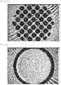
- FIG. 1 is a view illustrating a cliché for gravure printing, which is used when a pattern is formed by a gravure printing process in Example 1.
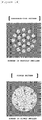
- FIG. 8 is a view illustrating a pattern formed by a gravure printing process in Example 1.
- FIG. 9 is a view illustrating a second bonding layer pattern which is any one of the patterns constituting the first bonding layer pattern of FIG. 8 .
- a bonding layer pattern was formed on one surface of a polyethylene separator by using the bonding layer solution prepared in Example 1, a coin cell was assembled to test the performance of the separator, and a coin cell resistance value of the separator was measured.
- the separator was first disposed inside a case in the form of a coin, and a coin cell was assembled in the order of a positive electrode, a separator, a spacer, a wave spring, a gasket, and a cover (negative electrode) from the lower portion thereof. Thereafter, the coin cell resistance value of the separator was measured by injecting an electrolytic solution thereinto.
- the coin cell resistance value was measured by using an electrochemical analyzer measurement apparatus manufactured by Solatron Co., Ltd.
- a bonding layer pattern was formed on both surfaces of a polyethylene separator by using the bonding layer solution prepared in Example 1, and a coin cell resistance value of the separator was measured.
- a first bonding layer pattern having an aperture ratio of 68% in a form of aggregate was formed on one surface of a polyethylene separator by using a gravure printing method, and a bonding strength between the first bonding layer pattern and the separator was measured.
- the bonding strength was measured by applying heat to the printed separator at 100°C at a rate of 1 m/min while allowing printing surfaces to face each other to stack the printed separators at a width of 25 mm, and performing a 180° peel test method.
- the patterns formed by the gravure printing process in Example 4 were regularly disposed at a gap of 500 ⁇ m.
- FIG. 1 is a view illustrating a cliché for gravure printing, which is used when a pattern is formed by a gravure printing process in Example 4.
- a bonding layer pattern was formed on both surfaces of a polyethylene separator by a gravure printing method using the bonding layer solution prepared in Example 1, and the wetting time according to the wetting of the electrolytic solution was recorded.
- a first bonding layer pattern was formed by using a cliché having no partition wall.
- FIG. 2 is a view illustrating a cliché for gravure printing, which is used when a pattern is formed by a gravure printing process in Comparative Example 1.
- the bonding layer solution prepared in Example 1 was used and fully coated on one surface of a polyethylene separator, and then a coin cell resistance value of the separator was measured.
- the bonding layer solution prepared in Example 1 was used and fully coated on both surfaces of a polyethylene separator, and then a coin cell resistance value of the separator was measured.
- a first bonding layer pattern having an aperture ratio of 80% in a form of aggregate was formed on one surface of a polyethylene separator by using a gravure printing method, and a bonding strength between the first bonding layer pattern and the separator was measured.
- the bonding strength was measured by applying heat to the printed separator at 100°C at a rate of 1 m/min while allowing printing surfaces to face each other to stack the printed separators at a width of 25 mm, and performing a 180° peel test method.
- FIG. 4 is a view illustrating a cliché for gravure printing, which is used when a pattern is formed by a gravure printing process in Comparative Example 4.
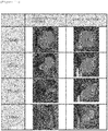
- FIG. 6 is a view illustrating a pattern formed by a gravure printing process in Comparative Example 4.
- a bonding strength between a bonding layer and a separator was measured without forming the bonding layer.
- the bonding strengths of the separators according to Example 4 and Comparative Examples 4 and 5 are shown in Table 1.
- FIG. 7 is a view illustrating the separator in which the bonding layer is not formed in Comparative Example 5.
- the bonding layer solution prepared in Example 1 was fully coated on both surfaces of a polyethylene separator by bar coating, and the wetting time according to the wetting of the electrolytic solution was recorded.
- the wetting was performed by the following method.
- the separators according to Example 5 (a pattern was formed on both surfaces of a separator) and Comparative Example 6 (a bonding layer solution was fully coated on both surfaces of a separator) were cut into 2 cm x 2 cm, and then the both surfaces of the separators were brought into contact with a polyethylene phthalate (PET) films having the same size, and laminated to the PET films while applying heat at 100°C at a rate of 1 m/min. And then, the separators were covered with an imide tape, and then wetted by pouring an electrolytic solution thereto. As the electrolytic solution, a propylene carbonate solvent was used. And then, after the wetting, the time taken until the entire surface was wetted was measured by using a stopwatch.
- PET polyethylene phthalate
- the wetting time of the separator with both surfaces patterned by a gravure printing process was shorter than that of the separator which was fully coated.
- the shorter wetting time means that the electrode and the separator inside the battery are smoothly wetted, and it is possible to improve the efficiency of performing the process by shortening the wetting time.
- the wetting speed is an element which is important for the battery performance when an electrolytic solution is injected into a battery in an assembly process of the battery. If the wetting of the separator is not performed well, and thus the wetting time is elongated, ions are not easily transferred, and as a result, a resistance acts against the battery.
- Bonding Strength (gf/25 mm)
- Example 4 (separator with a first bonding layer pattern having an aperture ratio of 68% and formed on one surface thereof) 21.19 Comparative Example 4 (separator with a first bonding layer pattern having an aperture ration of 80% and formed on one surface thereof) 7.32 Comparative Example 5 (separator which is not subjected to a printing process) 0
- the bonding strengths between the first bonding layer pattern and the separator are different from each other according to the aperture ratio of the pattern, and the smaller the aperture ratio of the pattern is, the greater the bonding strength of the separator is. Accordingly, the bonding strength can be adjusted according to the aperture ratio of the bonding layer pattern.
- the wetting time of the electrolytic solution for the separators according to Example 1 and Comparative Example 1 was measured. More specifically, the wetting time of the electrolytic solution for the separator according to Example 1 was 1 minute and 54 seconds, and the wetting time of the electrolytic solution for the separator according to Comparative Example 1 was 4 minutes and 12 seconds.
- the electrolytic solution wetting phenomenon for the separators in Example 1 and Comparative Example 1 is illustrated in the following FIG. 15 .
- a separator according to an exemplary embodiment of the present application may allow a bonding layer pattern to be easily printed by using a low viscous bonding composition which does not include an additive such as a thickener.
- the separator according to an exemplary embodiment of the present application has a characteristic in which a resistance acting inside a secondary battery is lower and a wetting time of an electrolytic solution is faster than when a bonding layer of the separator is formed by a full surface coating method, thereby having an effect in which excellent performance of the secondary battery may be implemented.
Landscapes
- Chemical & Material Sciences (AREA)
- Chemical Kinetics & Catalysis (AREA)
- Electrochemistry (AREA)
- General Chemical & Material Sciences (AREA)
- Engineering & Computer Science (AREA)
- Manufacturing & Machinery (AREA)
- Materials Engineering (AREA)
- Cell Separators (AREA)
Abstract
Description
- This application claims priority to and the benefit of Korean Patent Application No.
10-2015-0182167 - The present application relates to a separator and a battery comprising the same.
- The development and evolution of secondary batteries have become a motivation to actively expand mobile devices such as mobile phones, laptop computers, PCs, and portable multimedia players, and as the hybrid electric vehicle (HEV), mobile IT, intelligent robot industry, eco-friendly energy industry, and the like, which are the state-of-the art industries, have been developed, the secondary battery industry, which is an essential part of these industries, is required to be technically developed.
- Lithium ion batteries have excellent advantages in capacity, weight, self-discharge, memory effects, and the like compared to existing batteries based on nickel (nickel cadmium batteries and nickel hydrogen batteries), and thus is dominating the whole secondary battery market. Further, due to the advantage, the demand and application field thereof are increasing, and the lithium ion batteries have been usually applied to laptop computers, mobile phones, and the like, which require high capacity and a weight reduction. Currently, the biggest demand of the lithium secondary battery is laptop computers, PCs, mobile phones, and mobile electronic devices, and particularly, even though the lithium secondary battery is intermittently and repetitively charged, the lithium secondary battery can be used without deterioration in performance, so that it is possible to implement the most optimal characteristics for the use of mobile IT or futuristic automobiles.
- The core configuration, which constitutes a lithium secondary battery, is a positive electrode, a negative electrode, an electrolyte, and a separator, a polyethylene separator having micro pores is disposed between the positive electrode and the negative electrode, and the lithium secondary battery has a structure in which electricity is generated by an electrical flow in which lithium ions move through the electrolyte between the positive electrode and the negative electrode. The lithium ions move and pass through the separator, which is a porous membrane that blocks the positive electrode from being brought into contact with the negative electrode through the electrolyte. The lithium secondary battery is a battery in which electrodes are bonded to both surfaces of the separator by a binder, and typically, there is a problem in that the binder penetrates the separator in the form of a thin layer having low viscosity, and as a result, ion conductivity deteriorates, and the like. In order to solve the problem, studies have been conducted on the use of a highly viscous binder having high binding strength without penetrating the separator. An additive such as a thickener for increasing the viscosity as described above is added, and the addition of the additive negatively affects the movement of ions through the electrolyte and thus causes the performance of the lithium secondary battery to deteriorate.
- Further, a separator for which a porous substrate is widely used has a problem in that the separator exhibits anextreme heat shrinkage at a predetermined temperature due to material characteristics and characteristics in a manufacturing process including a process such as stretching, and thus a positive electrode and a negative electrode are brought into contact with each other. In order to solve the problem, studies have been conducted on a separator in which a coating layer is formed on at least one surface of a porous substrate. However, a binding strength between the electrode and the separator is reduced, and as a result, there may occur a problem in that lithium ions are not effectively transferred and the performance of the lithium secondary battery deteriorates. In addition, a bonding layer formed on an existing separator is formed by a full surface coating method and thus acts as a resistance in the movement of ions and causes the performance of the lithium secondary battery to deteriorate.
- An object of the present application is to provide a separator which allows a bonding layer pattern to be easily printed by using a low viscous bonding composition which does not include an additive such as a thickener, and may implement an excellent performance of a secondary battery by solving a problem of a resistance acting inside the secondary battery, which is generated when a bonding layer of the separator is formed by a full surface coating method.
- An exemplary embodiment of the present application provides a separator comprising: a porous substrate; and a first bonding layer pattern provided on at least one surface of the porous substrate, in which each pattern constituting the first bonding layer pattern consists of a second bonding layer pattern having an aperture ratio of 5% or more and 40% or less.
- Further, another exemplary embodiment of the present application provides a cliché for gravure printing, the cliche having a groove pattern provided on one surface thereof, in which at least one or more partition walls are comprised inside the groove.
- A separator according to an exemplary embodiment of the present application may allow a bonding layer pattern to be easily printed by using a low viscous bonding composition which does not include an additive such as a thickener.
- Further, the separator according to an exemplary embodiment of the present application has a characteristic in which a resistance acting inside a secondary battery is lower and a wetting time of an electrolytic solution is faster than when a bonding layer of the separator is formed by a full surface coating method, thereby having an effect in which an excellent performance of the secondary battery may be implemented.
-
-
FIG. 1 is a view illustrating a cliché for gravure printing, which is used when a pattern is formed by a gravure printing process in Example 1 and Example 4. -
FIG. 2 is a view illustrating a cliché for gravure printing, which is used when a pattern is formed by a gravure printing process in Comparative Example 1. -
FIG. 3 is a view illustrating a pattern formed by a gravure printing process in Comparative Example 1. -
FIG. 4 is a view illustrating a cliché for gravure printing, which is used when a pattern is formed by a gravure printing process in Comparative Example 4. -
FIG. 5 is a view illustrating a pattern formed by a gravure printing process in Example 4. -
FIG. 6 is a view illustrating a pattern formed by a gravure printing process in Comparative Example 4. -
FIG. 7 is a view illustrating a separator in which a bonding layer is not formed in Comparative Example 5. -
FIG. 8 is a view illustrating a pattern formed by a gravure printing process in Example 1. -
FIG. 9 is a view illustrating a second bonding layer pattern which is any one of the patterns constituting a first bonding layer pattern ofFIG. 8 . -
FIG. 10 is a view illustrating coin cell resistance results measured in Examples 2 and 3 and Comparative Examples 2 and 3. -
FIG. 11 is a view illustrating the wetting time according to Example 5 and Comparative Example 6. -
FIG. 12 is a view illustrating an example of a hollow second bonding layer pattern. -
FIG. 13 is a view schematically illustrating characteristics of a case where a bonding layer pattern is formed on a separator as in an exemplary embodiment of the present application and a case where a bonding layer is fully coated on a separator as in the related art. -
FIG. 14 is a view schematically illustrating characteristics of a case where a bonding layer pattern is in the form of aggregate as in an exemplary embodiment of the present application and a case where the bonding layer pattern is not in the form of aggregate, but in the form of a single pattern as in the related art. -
FIG. 15 is a view illustrating an electrolytic solution wetting phenomenon for the separators in Example 1 and Comparative Example 1. - Hereinafter, the present application will be described in more detail.
- When one part "comprises" one constituent element in the present specification, unless otherwise specifically described, this does not mean that another constituent element is excluded, but means that another constituent element may be further included.
- An exemplary embodiment of the present application provides a separator comprising: a porous substrate; and a first bonding layer pattern provided on at least one surface of the porous substrate, in which each pattern constituting the first bonding layer pattern consists of a second bonding layer pattern having an aperture ratio of 5% or more and 40% or less.
- The porous substrate may be a polyolefin-based porous substrate. The porous substrate may be, for example, a membrane-like substrate or a fibrous substrate, which is formed by using polyethylene, polypropylene, and the like either alone or in mixture thereof.
- As the porous substrate, it is possible to use, for example, a mixture multilayer separator, such as a two-layer separator of polyethylene/polypropylene, a three-layer separator of polyethylene/polypropylene/polyethylene, and a three-layer separator of polypropylene/polyethylene/polypropylene.
- An exemplary embodiment of the present application provides a separator in which the first bonding layer pattern has a total aperture ratio of 20% or more and less than 80%.
- The aperture ratio refers to a ratio of a region which is not covered by a pattern.
- When a lithium secondary battery is exemplified among batteries, in the lithium secondary battery, a separator is disposed between a positive electrode and a negative electrode, and electricity is generated by an electrical flow in which lithium ions move through the electrolyte between the positive electrode and the negative electrode.
- As the aperture ratio, which is a ratio of a region which is not covered by a pattern, is increased, there is an effect in which a channel capable of wetting a separator in an electrolytic solution is widened, and as a result, lithium ions smoothly move. However, when the aperture ratio is increased at a predetermined level or more, there is a problem in that an interfacial bonding strength between an electrode and a separator cannot be secured. Accordingly, it is important to appropriately adjust the aperture ratio for smooth moving lithium ions.
- The ion conductivity in the battery is affected by an amount of electrolytic solution wetting the separator, and when a separator into which a bonding layer pattern is introduced according to an exemplary embodiment of the present application is applied to a lithium secondary battery, there is an advantage in that a resistance acting inside the battery can be reduced by adjusting the aperture ratio. Accordingly, a lithium secondary battery adopting a separator into which a bonding layer pattern is introduced according to an exemplary embodiment of the present application has an effect of appropriately increasing an amount of electrolytic solution, and may obtain an effect in which the performance of the battery is better than that of a lithium secondary battery to which a separator into which a fully-coated bonding layer is introduced is applied.
-
FIG. 1 illustrates a cliché for gravure printing, which is used when a first bonding layer pattern having an aperture ratio of 68% is formed on one surface of a separator, andFIG. 4 illustrates a cliché for gravure printing, which is used when a first bonding layer pattern having an aperture ratio of 80% is formed on one surface of a separator. - According to the aperture ratio, the bonding strengths between the bonding layer pattern and the separator are different from each other, and specifically, the smaller the aperture ratio of pattern is, the more the bonding strength between the bonding layer pattern and the separator may be improved.
- In an exemplary embodiment of the present application, the form of each pattern constituting the second bonding layer pattern is characterized by comprising at least one of a circle, an ellipse, and a polygon. The polygon means a figure surrounded by three or more line segments, such as a triangle, a square, a pentagon, and a hexagon. However, the polygon is not limited thereto, and it is possible to apply all the forms which can be in the form of dots, such as a rhombus form and a fan form. Further, a form of each pattern constituting the second bonding layer pattern may be a wave form, an edge form of a circle, an edge form of an ellipse, an edge form of a triangle, and the like.
- In addition, referring to
FIG. 12 , the form of the second bonding layer pattern may be a hollow form. - In an exemplary embodiment of the present application, each pattern constituting the second bonding layer pattern may have a diameter of 10 µm to 100 µm.
- Each pattern constituting the second bonding layer pattern may be collected to form an aggregate. That is, in an exemplary embodiment of the present application, the first bonding layer pattern may consist of a second bonding layer pattern in the form of aggregate. When the bonding layer pattern is in the form of aggregate as in an exemplary embodiment of the present application, the binder is rapidly swollen, and when the bonding layer pattern is not in the form of aggregate, but in the form of a single pattern as in the related art, the binder is slowly swollen. The contents as described above are schematically illustrated in the following
FIG. 14 . - In an exemplary embodiment of the present application, a gap between patterns constituting the first bonding layer pattern may be disposed by regularly maintaining a predetermined gap.
- The gap between patterns constituting the first bonding layer pattern may be 100 µm to 1,000 µm.
- However, the gap is not limited thereto, and the gap between patterns constituting the first bonding layer pattern may be irregularly disposed.
- An exemplary embodiment of the present application provides a separator having a resistance of 0 ohm and more and 0.65 ohm or less.
- The resistance value according to an exemplary embodiment of the present application means a coin cell resistance value.
- In an exemplary embodiment of the present application, the second bonding layer pattern is formed from a bonding composition including a binder solution, a solvent, and a surfactant, and the bonding composition has a viscosity of more than 0 cP and less than 30 cP.
- An exemplary embodiment of the present application provides a separator in which the bonding composition comprises: 49 wt% to 70 wt% of a binder solution; 29 wt% to 50 wt% of a solvent; and 0.1 wt% to 10 wt% of a surfactant, based on a total weight of the bonding composition.
- The binder solution may comprise a binder resin and a solvent.
- The binder resin may be an aqueous or oily emulsion type, and the binder solution may include 15 wt% to 40 wt% of a binder and 60 wt% to 85 wt% of water.
- Examples of the binder resin included in the binder solution include acrylate-series of methyl acrylate, ethyl acrylate, n-propyl acrylate, isopropyl acrylate, n-butyl acrylate, t-butyl acrylate, pentyl acrylate, hexyl acrylate, heptyl acrylate, octyl acrylate, 2-ethylhexyl acrylate, nonyl acrylate, decyl acrylate, lauryl acrylate, n-tetradecyl acrylate, stearyl acrylate, methyl methacrylate, ethyl methacrylate, n-propyl methacrylate, isopropyl methacrylate, n-butyl methacrylate, t-butyl methacrylate, pentyl methacrylate, hexyl methacrylate, heptyl methacrylate, octyl methacrylate, 2-ethylhexyl methacrylate, nonyl methacrylate, decyl methacrylate, lauryl methacrylate, n-tetradecyl methacrylate, stearyl methacrylate and the like, polyvinylidene fluoride series of polyvinylidene fluoride, polyvinylidene fluoride-hexafluoropropylene, polyvinylidene fluoride-trichloroethylene, polyvinylidene fluoride-chlorotrifluoro ethylene and the like.
- Further, examples of the solvent included in the binder solution include water; alcohols such as ethanol, methanol, isopropanol, butanol, ethylene glycol, and ethylene glycol monomethyl ether; amides such as N-methylpyrrolidone and N,N-dimethylformamide; ketones such as acetone, ethyl methyl ketone, diisopropyl ketone, cyclohexanone, methylcyclohexane, and ethylcyclohexane; cyclic aliphatic hydrocarbons such as cyclopentane and cyclohexane; aromatic hydrocarbons such as toluene, xylene, and ethylbenzene; and the like.
- The solvent included in the bonding composition may include water, and may include one or two or more selected from the group consisting of methanol, ethanol, propanol, and butanol.
- Furthermore, the solvent may include: ester-based compounds such as methyl acetate, ethyl acetate, and butyl acetate; ketone-based compounds such as acetone, methyl ethyl ketone, methyl isobutyl ketone, and cyclohexanone; alcohol derivatives such as methyl cellosolve, ethyl cellosolve, and butyl cellosolve; aromatic hydrocarbon-based compounds such as benzole, toluole, and xylol; or aliphatic hydrocarbon-based compounds such as n-hexane and cyclohexane.
- The bonding composition is characterized by not including an additive such as a thickener, and an exemplary embodiment of the present application has an advantage in that a pattern of a bonding layer is easily formed even by using a low viscous bonding composition. An additive added to increase the viscosity acts as an element of resistance to ion transfer inside a battery, and there is a problem in that the additive is wetted in an electrolytic solution, and negatively affects the movement of ions of the electrolytic solution, thereby making the performance of the battery deteriorate.
- When a bonding layer pattern is formed on one surface or both surfaces of a separator by using the bonding layer composition, the first bonding layer pattern may allow the separator to be efficiently wetted by increasing the contact surface area of the electrolytic solution acting on the separator and allowing the electrolytic solution to smoothly move. Further, the second bonding layer pattern serves to smoothly swell the first bonding layer pattern itself.
- Accordingly, an exemplary embodiment of the present application may allow the separator to be smoothly wetted and swollen by forming a bonding layer pattern on the separator, compared to the case where a bonding layer solution is fully coated on the separator, and accordingly, there is an effect capable of obtaining an excellent performance of the battery. When a bonding layer pattern is formed on a separator as in an exemplary embodiment of the present application, the electrolytic solution is easily penetrated, and when a bonding layer is fully coated on a separator as in the related art, it is difficult for the electrolytic solution to be penetrated. The contents as described above are schematically illustrated in the following
FIG. 13 . - An exemplary embodiment of the present application provides a separator in which a second bonding layer pattern is formed by using a gravure printing method.
- The gravure printing method refers to a method performed in the following manner. First, a groove is formed at a specific position of an intaglio or a cliché of a printing substrate corresponding to a pattern to be formed, and then the inside of the groove is filled with ink. The inside of the groove is filled with an ink in a state where gravure ink for forming a pattern is applied to an upper portion of the cliché, and then a doctor blade is brought into contact with the cliché. By the progress of the doctor blade, the inside of the groove is filled with the ink, and simultaneously, the ink in a non-pattern portion remaining on the surface of the cliché is removed.
- Further, printing is performed by directly adhering the cliché to an object to be printed in a state where the cliché is filled with the ink.
- The aperture ratio of the pattern according to an exemplary embodiment of the present application is adjusted by a method for manufacturing a printing substrate by fixing a diameter of a first bonding layer pattern in a pattern portion of the printing substrate such as the intaglio or the cliché, and adjusting the size and gap of a second bonding layer pattern.
- An exemplary embodiment of the present application provides a battery comprising the separator according to an exemplary embodiment of the present application.
- The battery includes: a positive electrode; a negative electrode; and a separator interposed between the positive electrode and the negative electrode. The battery may be a lithium battery, but is not limited thereto.
- Among the lithium batteries, a lithium secondary battery may be classified into a lithium ion battery, a lithium ion polymer battery, and a lithium polymer battery according to the types of separator and electrolyte used, and may be classified into a cylindrical shape, an angular shape, a coin shape, a pouch shape, and the like according to the shape thereof. Further, the lithium secondary battery may be classified into a bulk type and a thin-film type according to the size thereof.
- The lithium secondary battery according to an exemplary embodiment of the present application is not particularly limited in shape.
- An exemplary embodiment of the present application provides a cliché for gravure printing, the cliché having a groove pattern provided on one surface thereof, in which at least one or more partition walls are comprised inside the groove.
- The partition wall may have a height of 5 µm to 50 µm and a width of 5 µm to 50 µm.
- An exemplary embodiment of the present application provides a cliché for gravure printing, the cliché comprising at least two or more partition walls inside the groove, in which a gap between the partition walls is 10 µm to 100 µm.
- The partition wall may be in form of a dot, a line, or a mesh.
- Hereinafter, the present specification will be described in detail with reference to Examples for more specifically describing the present specification. However, the Examples according to the present specification may be modified in various forms, and it is not interpreted that the scope of the present specification is limited to the Examples described below in detail. The Examples of the present specification are provided for more completely explaining the present specification to a person with ordinary skill in the art.
- A bonding layer solution including 60 wt% of a PX-LP17 binder solution manufactured by ZEON Corporation, 38 wt% to 39 wt% of ethanol, and 1 wt% to 2 wt% of a WE3475 surfactant manufactured by Basf Corporation was prepared. A first bonding layer pattern was formed on one surface of a prepared polyethylene separator by a gravure printing process. And then, when the gravure printing process was performed, a pattern was formed by using a cliché including at least one or more partition walls.
- The first bonding layer pattern was printed so as to have an aggregate shape, and a second bonding layer pattern, which is each pattern constituting the first bonding layer pattern, had a circular shape having a diameter of 35 µm, and the second bonding layer pattern had an aperture ratio of 8%. Further, the first bonding layer pattern had a total aperture ratio of 68%.
-
FIG. 1 is a view illustrating a cliché for gravure printing, which is used when a pattern is formed by a gravure printing process in Example 1. -
FIG. 8 is a view illustrating a pattern formed by a gravure printing process in Example 1.FIG. 9 is a view illustrating a second bonding layer pattern which is any one of the patterns constituting the first bonding layer pattern ofFIG. 8 . - A bonding layer pattern was formed on one surface of a polyethylene separator by using the bonding layer solution prepared in Example 1, a coin cell was assembled to test the performance of the separator, and a coin cell resistance value of the separator was measured.
- In order to measure the coin cell resistance value, the separator was first disposed inside a case in the form of a coin, and a coin cell was assembled in the order of a positive electrode, a separator, a spacer, a wave spring, a gasket, and a cover (negative electrode) from the lower portion thereof. Thereafter, the coin cell resistance value of the separator was measured by injecting an electrolytic solution thereinto.
- The coin cell resistance value was measured by using an electrochemical analyzer measurement apparatus manufactured by Solatron Co., Ltd.
- A bonding layer pattern was formed on both surfaces of a polyethylene separator by using the bonding layer solution prepared in Example 1, and a coin cell resistance value of the separator was measured.
- A first bonding layer pattern having an aperture ratio of 68% in a form of aggregate was formed on one surface of a polyethylene separator by using a gravure printing method, and a bonding strength between the first bonding layer pattern and the separator was measured.
- The bonding strength was measured by applying heat to the printed separator at 100°C at a rate of 1 m/min while allowing printing surfaces to face each other to stack the printed separators at a width of 25 mm, and performing a 180° peel test method.
- Referring to
FIG. 5 , it can be confirmed that the patterns formed by the gravure printing process in Example 4 were regularly disposed at a gap of 500 µm. -
FIG. 1 is a view illustrating a cliché for gravure printing, which is used when a pattern is formed by a gravure printing process in Example 4. - A bonding layer pattern was formed on both surfaces of a polyethylene separator by a gravure printing method using the bonding layer solution prepared in Example 1, and the wetting time according to the wetting of the electrolytic solution was recorded.
- Unlike Example 1, a first bonding layer pattern was formed by using a cliché having no partition wall.
- Referring to
FIG. 3 , it can be confirmed that the patterns formed by a gravure printing process in Comparative Example 1 did not form an aggregate shape and were very irregularly disposed. -
FIG. 2 is a view illustrating a cliché for gravure printing, which is used when a pattern is formed by a gravure printing process in Comparative Example 1. - The bonding layer solution prepared in Example 1 was used and fully coated on one surface of a polyethylene separator, and then a coin cell resistance value of the separator was measured.
- The bonding layer solution prepared in Example 1 was used and fully coated on both surfaces of a polyethylene separator, and then a coin cell resistance value of the separator was measured.
- The coin cell resistance values measured in Examples 2 and 3 and Comparative Examples 2 and 3 are illustrated in
FIG. 10 . - A first bonding layer pattern having an aperture ratio of 80% in a form of aggregate was formed on one surface of a polyethylene separator by using a gravure printing method, and a bonding strength between the first bonding layer pattern and the separator was measured. The bonding strength was measured by applying heat to the printed separator at 100°C at a rate of 1 m/min while allowing printing surfaces to face each other to stack the printed separators at a width of 25 mm, and performing a 180° peel test method.
-
FIG. 4 is a view illustrating a cliché for gravure printing, which is used when a pattern is formed by a gravure printing process in Comparative Example 4. -
FIG. 6 is a view illustrating a pattern formed by a gravure printing process in Comparative Example 4. - A bonding strength between a bonding layer and a separator was measured without forming the bonding layer. The bonding strengths of the separators according to Example 4 and Comparative Examples 4 and 5 are shown in Table 1.
-
FIG. 7 is a view illustrating the separator in which the bonding layer is not formed in Comparative Example 5. - The bonding layer solution prepared in Example 1 was fully coated on both surfaces of a polyethylene separator by bar coating, and the wetting time according to the wetting of the electrolytic solution was recorded.
- The wetting was performed by the following method.
- The separators according to Example 5 (a pattern was formed on both surfaces of a separator) and Comparative Example 6 (a bonding layer solution was fully coated on both surfaces of a separator) were cut into 2 cm x 2 cm, and then the both surfaces of the separators were brought into contact with a polyethylene phthalate (PET) films having the same size, and laminated to the PET films while applying heat at 100°C at a rate of 1 m/min. And then, the separators were covered with an imide tape, and then wetted by pouring an electrolytic solution thereto. As the electrolytic solution, a propylene carbonate solvent was used. And then, after the wetting, the time taken until the entire surface was wetted was measured by using a stopwatch.
- The wetting time according to Example 5 and Comparative Example 6 were measured, and the results are shown in
FIG. 11 . - When the results of measuring the wetting time of the separator were compared with each other, it can be confirmed that the wetting time of the separator with both surfaces patterned by a gravure printing process was shorter than that of the separator which was fully coated. The shorter wetting time means that the electrode and the separator inside the battery are smoothly wetted, and it is possible to improve the efficiency of performing the process by shortening the wetting time.
- The wetting speed is an element which is important for the battery performance when an electrolytic solution is injected into a battery in an assembly process of the battery. If the wetting of the separator is not performed well, and thus the wetting time is elongated, ions are not easily transferred, and as a result, a resistance acts against the battery.
[Table 1] Bonding Strength (gf/25 mm) Example 4 (separator with a first bonding layer pattern having an aperture ratio of 68% and formed on one surface thereof) 21.19 Comparative Example 4 (separator with a first bonding layer pattern having an aperture ration of 80% and formed on one surface thereof) 7.32 Comparative Example 5 (separator which is not subjected to a printing process) 0 - As can be confirmed in Table 1, it is shown that the bonding strengths between the first bonding layer pattern and the separator are different from each other according to the aperture ratio of the pattern, and the smaller the aperture ratio of the pattern is, the greater the bonding strength of the separator is. Accordingly, the bonding strength can be adjusted according to the aperture ratio of the bonding layer pattern.
- The wetting time of the electrolytic solution for the separators according to Example 1 and Comparative Example 1 was measured. More specifically, the wetting time of the electrolytic solution for the separator according to Example 1 was 1 minute and 54 seconds, and the wetting time of the electrolytic solution for the separator according to Comparative Example 1 was 4 minutes and 12 seconds. The electrolytic solution wetting phenomenon for the separators in Example 1 and Comparative Example 1 is illustrated in the following
FIG. 15 . - As in the results, a separator according to an exemplary embodiment of the present application may allow a bonding layer pattern to be easily printed by using a low viscous bonding composition which does not include an additive such as a thickener.
- Further, the separator according to an exemplary embodiment of the present application has a characteristic in which a resistance acting inside a secondary battery is lower and a wetting time of an electrolytic solution is faster than when a bonding layer of the separator is formed by a full surface coating method, thereby having an effect in which excellent performance of the secondary battery may be implemented.
Claims (13)
- A separator comprising:a porous substrate; anda first bonding layer pattern provided on at least one surface of the porous substrate,wherein each pattern constituting the first bonding layer pattern consists of a second bonding layer pattern having an aperture ratio of 5% or more and 40% or less.
- The separator of claim 1, wherein the first bonding layer pattern has a total aperture ratio of 20% or more and less than 80%.
- The separator of claim 1, wherein a form of each pattern constituting the second bonding layer pattern comprises at least one of a circle, an ellipse, and a polygon.
- The separator of claim 1, wherein each pattern constituting the second bonding layer pattern has a diameter of 10 µm to 100 µm.
- The separator of claim 1, wherein a gap between patterns constituting the first bonding layer pattern is 100 µm to 1,000 µm.
- The separator of claim 1, wherein the separator has a resistance of 0 ohm and more and 0.65 ohm or less.
- The separator of claim 1, wherein the second bonding layer pattern is formed from a bonding composition comprising a binder solution, a solvent, and a surfactant, and
the bonding composition has a viscosity of more than 0 cP and less than 30 cP. - The separator of claim 7, wherein the bonding composition comprises 49 wt% to 70 wt% of a binder solution, 29 wt% to 50 wt% of a solvent, and 0.1 wt% to 10 wt% of a surfactant, based on a total weight of the bonding composition.
- The separator of claim 1, wherein the second bonding layer pattern is formed by using a gravure printing method.
- A battery comprising the separator of any one of claims 1 to 9.
- A cliché for gravure printing, the cliché having a groove pattern provided on one surface thereof,
wherein at least one or more partition walls are comprised inside the groove. - The cliché of claim 11, wherein the partition wall has a height of 5 µm to 50 µm and a width of 5 µm to 50 µm.
- The cliché of claim 11, wherein at least two or more partition walls are comprised inside the groove, and
a gap between the partition walls is 10 µm to 100 µm.
Applications Claiming Priority (2)
| Application Number | Priority Date | Filing Date | Title |
|---|---|---|---|
| KR20150182167 | 2015-12-18 | ||
| PCT/KR2016/014882 WO2017105156A1 (en) | 2015-12-18 | 2016-12-19 | Separator and battery comprising same |
Publications (3)
| Publication Number | Publication Date |
|---|---|
| EP3376563A1 true EP3376563A1 (en) | 2018-09-19 |
| EP3376563A4 EP3376563A4 (en) | 2019-01-16 |
| EP3376563B1 EP3376563B1 (en) | 2020-09-23 |
Family
ID=59056905
Family Applications (1)
| Application Number | Title | Priority Date | Filing Date |
|---|---|---|---|
| EP16876098.1A Active EP3376563B1 (en) | 2015-12-18 | 2016-12-19 | Separator and battery comprising same |
Country Status (6)
| Country | Link |
|---|---|
| US (1) | US10804559B2 (en) |
| EP (1) | EP3376563B1 (en) |
| JP (1) | JP6734387B2 (en) |
| KR (1) | KR102050627B1 (en) |
| CN (1) | CN108431992B (en) |
| WO (1) | WO2017105156A1 (en) |
Families Citing this family (5)
| Publication number | Priority date | Publication date | Assignee | Title |
|---|---|---|---|---|
| KR102354261B1 (en) * | 2018-06-12 | 2022-01-20 | 주식회사 엘지화학 | Separator for electrochemical device, comprising a patterned adhesive layer and a method of manufacturing the separator |
| CN111129406A (en) * | 2019-12-31 | 2020-05-08 | 湖北亿纬动力有限公司 | Water-system high-viscosity gluing diaphragm, preparation method thereof and application thereof in battery |
| CN111312967B (en) * | 2020-02-27 | 2022-06-07 | 河北金力新能源科技股份有限公司 | Ceramic coating slurry and preparation method thereof, lithium battery diaphragm and lithium battery |
| EP4358273A1 (en) | 2021-09-07 | 2024-04-24 | Asahi Kasei Kabushiki Kaisha | Separator for power storage device |
| WO2024106803A1 (en) * | 2022-11-18 | 2024-05-23 | 주식회사 엘지화학 | Lithium secondary battery |
Family Cites Families (13)
| Publication number | Priority date | Publication date | Assignee | Title |
|---|---|---|---|---|
| KR100363270B1 (en) * | 1999-12-20 | 2002-11-30 | 주식회사 코캄엔지니어링 | Electrode assembly for lithium secondary battery manufacturing method and apparatus thereof |
| CN103081181B (en) | 2010-08-31 | 2016-03-02 | 日本瑞翁株式会社 | The manufacture method of battery perforated membrane paste compound, secondary cell perforated membrane, secondary cell perforated membrane, electrode for secondary battery, secondary cell dividing plate and secondary cell |
| CA2811248C (en) | 2010-09-17 | 2017-08-15 | Creative Co. Ltd. | Solid fuel |
| KR101281037B1 (en) * | 2011-04-06 | 2013-07-09 | 주식회사 엘지화학 | Separator and electrochemical device comprising the same |
| US9276247B2 (en) | 2011-04-06 | 2016-03-01 | Lg Chem, Ltd. | Separator and electrochemical device comprising the same |
| KR101491061B1 (en) * | 2012-05-03 | 2015-02-10 | 주식회사 엘지화학 | Electrode assembly and preparation thereof |
| US8921841B2 (en) * | 2012-05-09 | 2014-12-30 | Samsung Corning Precision Materials Co., Ltd. | Porous glass substrate for displays and method of manufacturing the same |
| CN103450444B (en) | 2013-08-22 | 2015-09-02 | 江苏科技大学 | A kind of fluorine silicon Modified Waterborne Polyurethane emulsion and preparation method thereof |
| CN105684190A (en) * | 2013-10-25 | 2016-06-15 | Lg化学株式会社 | Method for applying adhesive binder to separation membrane |
| CN104871346B (en) | 2013-11-04 | 2017-10-13 | 株式会社Lg 化学 | The method for forming secondary cell adhesive layer |
| KR20150057481A (en) * | 2013-11-19 | 2015-05-28 | 삼성에스디아이 주식회사 | Separator for lithium battery, lithium battery including the same, and method for preparing the lithium battery |
| KR20150057480A (en) * | 2013-11-19 | 2015-05-28 | 삼성에스디아이 주식회사 | Separator, lithium battery including the same, method for preparing the separator, and method for preparing the lithium battery |
| JP2015141838A (en) * | 2014-01-29 | 2015-08-03 | 旭化成イーマテリアルズ株式会社 | Separator for power storage device, power storage device, lithium ion secondary battery, and copolymer |
-
2016
- 2016-12-19 WO PCT/KR2016/014882 patent/WO2017105156A1/en active Application Filing
- 2016-12-19 CN CN201680073097.6A patent/CN108431992B/en active Active
- 2016-12-19 KR KR1020160173728A patent/KR102050627B1/en active IP Right Grant
- 2016-12-19 JP JP2018545796A patent/JP6734387B2/en active Active
- 2016-12-19 EP EP16876098.1A patent/EP3376563B1/en active Active
- 2016-12-19 US US15/779,275 patent/US10804559B2/en active Active
Also Published As
| Publication number | Publication date |
|---|---|
| EP3376563A4 (en) | 2019-01-16 |
| US10804559B2 (en) | 2020-10-13 |
| CN108431992B (en) | 2021-07-16 |
| CN108431992A (en) | 2018-08-21 |
| EP3376563B1 (en) | 2020-09-23 |
| KR20170073539A (en) | 2017-06-28 |
| US20180351194A1 (en) | 2018-12-06 |
| JP2018535534A (en) | 2018-11-29 |
| JP6734387B2 (en) | 2020-08-05 |
| WO2017105156A1 (en) | 2017-06-22 |
| KR102050627B1 (en) | 2019-12-02 |
Similar Documents
| Publication | Publication Date | Title |
|---|---|---|
| EP3376563B1 (en) | Separator and battery comprising same | |
| CN110197888B (en) | Battery diaphragm and lithium ion battery | |
| KR101485387B1 (en) | Separator for electrochemical device, electrochemical device using same, and method for producing the separator for electrochemical device | |
| KR100736512B1 (en) | Lithium ion secondary battery | |
| JP6148331B2 (en) | Method for producing porous / separated porous membrane for lithium secondary battery using aqueous coating solution | |
| JP6092389B2 (en) | Organic / inorganic composite coating porous separation membrane and secondary battery element using the same | |
| CN110071293B (en) | Battery cell and battery, liquid-retaining coating and battery pole piece and preparation method thereof | |
| EP2983228A1 (en) | Electrochemical energy storage device | |
| KR101980974B1 (en) | Method for producing negative electrode and secondary battery, and secondary battery | |
| US11133560B2 (en) | Insulating tape and li-ion battery adopting the same | |
| EP3232501A1 (en) | Electrochemical energy storage device | |
| WO2015026656A1 (en) | Li-metal battery with microstructured solid electrolyte | |
| KR20140071951A (en) | Heat resistant porous membrane, separator for nonaqueous cell, and nonaqueous cell | |
| EP2713420B1 (en) | Electric storage device, and vehicle mounted electric storage system | |
| JP5017995B2 (en) | Method for manufacturing electrode plate for lithium secondary battery, electrode plate for lithium secondary battery and lithium secondary battery using the method | |
| US20180233730A1 (en) | Multi-layered porous film, separator for power storage device, and power storage device | |
| CN107437623B (en) | Lithium ion battery positive plate and preparation method thereof | |
| JPWO2011114473A1 (en) | Method for manufacturing battery electrode | |
| KR102077274B1 (en) | Separator for electrochemical device, manufacturing maehotd thereof and electrochemical divice comprising the same | |
| KR101909318B1 (en) | An organic-inoranic composite porous layer, a seperator and an electrode structure comprising the same | |
| JP5888079B2 (en) | Separator and non-aqueous secondary battery using the same | |
| KR20160051167A (en) | Manufacturing method of a porous coated complex separator and separator manufactured by its method | |
| JP2019117700A (en) | Manufacturing method of laminated electrode body | |
| JP6264780B2 (en) | Electrode manufacturing method and electrode manufacturing apparatus | |
| CN113097440A (en) | Electrochemical device and electric equipment |
Legal Events
| Date | Code | Title | Description |
|---|---|---|---|
| STAA | Information on the status of an ep patent application or granted ep patent |
Free format text: STATUS: THE INTERNATIONAL PUBLICATION HAS BEEN MADE |
|
| PUAI | Public reference made under article 153(3) epc to a published international application that has entered the european phase |
Free format text: ORIGINAL CODE: 0009012 |
|
| STAA | Information on the status of an ep patent application or granted ep patent |
Free format text: STATUS: REQUEST FOR EXAMINATION WAS MADE |
|
| 17P | Request for examination filed |
Effective date: 20180612 |
|
| AK | Designated contracting states |
Kind code of ref document: A1 Designated state(s): AL AT BE BG CH CY CZ DE DK EE ES FI FR GB GR HR HU IE IS IT LI LT LU LV MC MK MT NL NO PL PT RO RS SE SI SK SM TR |
|
| AX | Request for extension of the european patent |
Extension state: BA ME |
|
| A4 | Supplementary search report drawn up and despatched |
Effective date: 20181219 |
|
| RIC1 | Information provided on ipc code assigned before grant |
Ipc: H01M 2/14 20060101ALI20181213BHEP Ipc: H01M 2/16 20060101AFI20181213BHEP Ipc: H01M 10/0525 20100101ALI20181213BHEP |
|
| DAV | Request for validation of the european patent (deleted) | ||
| DAX | Request for extension of the european patent (deleted) | ||
| GRAP | Despatch of communication of intention to grant a patent |
Free format text: ORIGINAL CODE: EPIDOSNIGR1 |
|
| STAA | Information on the status of an ep patent application or granted ep patent |
Free format text: STATUS: GRANT OF PATENT IS INTENDED |
|
| INTG | Intention to grant announced |
Effective date: 20191128 |
|
| GRAS | Grant fee paid |
Free format text: ORIGINAL CODE: EPIDOSNIGR3 |
|
| GRAA | (expected) grant |
Free format text: ORIGINAL CODE: 0009210 |
|
| STAA | Information on the status of an ep patent application or granted ep patent |
Free format text: STATUS: THE PATENT HAS BEEN GRANTED |
|
| AK | Designated contracting states |
Kind code of ref document: B1 Designated state(s): AL AT BE BG CH CY CZ DE DK EE ES FI FR GB GR HR HU IE IS IT LI LT LU LV MC MK MT NL NO PL PT RO RS SE SI SK SM TR |
|
| REG | Reference to a national code |
Ref country code: GB Ref legal event code: FG4D |
|
| REG | Reference to a national code |
Ref country code: CH Ref legal event code: EP |
|
| REG | Reference to a national code |
Ref country code: IE Ref legal event code: FG4D |
|
| REG | Reference to a national code |
Ref country code: AT Ref legal event code: REF Ref document number: 1317292 Country of ref document: AT Kind code of ref document: T Effective date: 20201015 Ref country code: DE Ref legal event code: R096 Ref document number: 602016044747 Country of ref document: DE |
|
| REG | Reference to a national code |
Ref country code: DE Ref legal event code: R079 Ref document number: 602016044747 Country of ref document: DE Free format text: PREVIOUS MAIN CLASS: H01M0002160000 Ipc: H01M0050409000 |
|
| PG25 | Lapsed in a contracting state [announced via postgrant information from national office to epo] |
Ref country code: FI Free format text: LAPSE BECAUSE OF FAILURE TO SUBMIT A TRANSLATION OF THE DESCRIPTION OR TO PAY THE FEE WITHIN THE PRESCRIBED TIME-LIMIT Effective date: 20200923 Ref country code: HR Free format text: LAPSE BECAUSE OF FAILURE TO SUBMIT A TRANSLATION OF THE DESCRIPTION OR TO PAY THE FEE WITHIN THE PRESCRIBED TIME-LIMIT Effective date: 20200923 Ref country code: SE Free format text: LAPSE BECAUSE OF FAILURE TO SUBMIT A TRANSLATION OF THE DESCRIPTION OR TO PAY THE FEE WITHIN THE PRESCRIBED TIME-LIMIT Effective date: 20200923 Ref country code: BG Free format text: LAPSE BECAUSE OF FAILURE TO SUBMIT A TRANSLATION OF THE DESCRIPTION OR TO PAY THE FEE WITHIN THE PRESCRIBED TIME-LIMIT Effective date: 20201223 Ref country code: GR Free format text: LAPSE BECAUSE OF FAILURE TO SUBMIT A TRANSLATION OF THE DESCRIPTION OR TO PAY THE FEE WITHIN THE PRESCRIBED TIME-LIMIT Effective date: 20201224 Ref country code: NO Free format text: LAPSE BECAUSE OF FAILURE TO SUBMIT A TRANSLATION OF THE DESCRIPTION OR TO PAY THE FEE WITHIN THE PRESCRIBED TIME-LIMIT Effective date: 20201223 |
|
| REG | Reference to a national code |
Ref country code: AT Ref legal event code: MK05 Ref document number: 1317292 Country of ref document: AT Kind code of ref document: T Effective date: 20200923 |
|
| PG25 | Lapsed in a contracting state [announced via postgrant information from national office to epo] |
Ref country code: RS Free format text: LAPSE BECAUSE OF FAILURE TO SUBMIT A TRANSLATION OF THE DESCRIPTION OR TO PAY THE FEE WITHIN THE PRESCRIBED TIME-LIMIT Effective date: 20200923 Ref country code: LV Free format text: LAPSE BECAUSE OF FAILURE TO SUBMIT A TRANSLATION OF THE DESCRIPTION OR TO PAY THE FEE WITHIN THE PRESCRIBED TIME-LIMIT Effective date: 20200923 |
|
| REG | Reference to a national code |
Ref country code: NL Ref legal event code: MP Effective date: 20200923 |
|
| REG | Reference to a national code |
Ref country code: LT Ref legal event code: MG4D |
|
| PG25 | Lapsed in a contracting state [announced via postgrant information from national office to epo] |
Ref country code: EE Free format text: LAPSE BECAUSE OF FAILURE TO SUBMIT A TRANSLATION OF THE DESCRIPTION OR TO PAY THE FEE WITHIN THE PRESCRIBED TIME-LIMIT Effective date: 20200923 Ref country code: SM Free format text: LAPSE BECAUSE OF FAILURE TO SUBMIT A TRANSLATION OF THE DESCRIPTION OR TO PAY THE FEE WITHIN THE PRESCRIBED TIME-LIMIT Effective date: 20200923 Ref country code: LT Free format text: LAPSE BECAUSE OF FAILURE TO SUBMIT A TRANSLATION OF THE DESCRIPTION OR TO PAY THE FEE WITHIN THE PRESCRIBED TIME-LIMIT Effective date: 20200923 Ref country code: PT Free format text: LAPSE BECAUSE OF FAILURE TO SUBMIT A TRANSLATION OF THE DESCRIPTION OR TO PAY THE FEE WITHIN THE PRESCRIBED TIME-LIMIT Effective date: 20210125 Ref country code: RO Free format text: LAPSE BECAUSE OF FAILURE TO SUBMIT A TRANSLATION OF THE DESCRIPTION OR TO PAY THE FEE WITHIN THE PRESCRIBED TIME-LIMIT Effective date: 20200923 Ref country code: CZ Free format text: LAPSE BECAUSE OF FAILURE TO SUBMIT A TRANSLATION OF THE DESCRIPTION OR TO PAY THE FEE WITHIN THE PRESCRIBED TIME-LIMIT Effective date: 20200923 |
|
| PG25 | Lapsed in a contracting state [announced via postgrant information from national office to epo] |
Ref country code: PL Free format text: LAPSE BECAUSE OF FAILURE TO SUBMIT A TRANSLATION OF THE DESCRIPTION OR TO PAY THE FEE WITHIN THE PRESCRIBED TIME-LIMIT Effective date: 20200923 Ref country code: IS Free format text: LAPSE BECAUSE OF FAILURE TO SUBMIT A TRANSLATION OF THE DESCRIPTION OR TO PAY THE FEE WITHIN THE PRESCRIBED TIME-LIMIT Effective date: 20210123 Ref country code: ES Free format text: LAPSE BECAUSE OF FAILURE TO SUBMIT A TRANSLATION OF THE DESCRIPTION OR TO PAY THE FEE WITHIN THE PRESCRIBED TIME-LIMIT Effective date: 20200923 Ref country code: AT Free format text: LAPSE BECAUSE OF FAILURE TO SUBMIT A TRANSLATION OF THE DESCRIPTION OR TO PAY THE FEE WITHIN THE PRESCRIBED TIME-LIMIT Effective date: 20200923 Ref country code: AL Free format text: LAPSE BECAUSE OF FAILURE TO SUBMIT A TRANSLATION OF THE DESCRIPTION OR TO PAY THE FEE WITHIN THE PRESCRIBED TIME-LIMIT Effective date: 20200923 |
|
| REG | Reference to a national code |
Ref country code: DE Ref legal event code: R097 Ref document number: 602016044747 Country of ref document: DE |
|
| PG25 | Lapsed in a contracting state [announced via postgrant information from national office to epo] |
Ref country code: SK Free format text: LAPSE BECAUSE OF FAILURE TO SUBMIT A TRANSLATION OF THE DESCRIPTION OR TO PAY THE FEE WITHIN THE PRESCRIBED TIME-LIMIT Effective date: 20200923 |
|
| PLBE | No opposition filed within time limit |
Free format text: ORIGINAL CODE: 0009261 |
|
| REG | Reference to a national code |
Ref country code: CH Ref legal event code: PL |
|
| STAA | Information on the status of an ep patent application or granted ep patent |
Free format text: STATUS: NO OPPOSITION FILED WITHIN TIME LIMIT |
|
| PG25 | Lapsed in a contracting state [announced via postgrant information from national office to epo] |
Ref country code: SI Free format text: LAPSE BECAUSE OF FAILURE TO SUBMIT A TRANSLATION OF THE DESCRIPTION OR TO PAY THE FEE WITHIN THE PRESCRIBED TIME-LIMIT Effective date: 20200923 Ref country code: DK Free format text: LAPSE BECAUSE OF FAILURE TO SUBMIT A TRANSLATION OF THE DESCRIPTION OR TO PAY THE FEE WITHIN THE PRESCRIBED TIME-LIMIT Effective date: 20200923 Ref country code: MC Free format text: LAPSE BECAUSE OF FAILURE TO SUBMIT A TRANSLATION OF THE DESCRIPTION OR TO PAY THE FEE WITHIN THE PRESCRIBED TIME-LIMIT Effective date: 20200923 |
|
| 26N | No opposition filed |
Effective date: 20210624 |
|
| REG | Reference to a national code |
Ref country code: BE Ref legal event code: MM Effective date: 20201231 |
|
| PG25 | Lapsed in a contracting state [announced via postgrant information from national office to epo] |
Ref country code: IE Free format text: LAPSE BECAUSE OF NON-PAYMENT OF DUE FEES Effective date: 20201219 Ref country code: LU Free format text: LAPSE BECAUSE OF NON-PAYMENT OF DUE FEES Effective date: 20201219 Ref country code: IT Free format text: LAPSE BECAUSE OF FAILURE TO SUBMIT A TRANSLATION OF THE DESCRIPTION OR TO PAY THE FEE WITHIN THE PRESCRIBED TIME-LIMIT Effective date: 20200923 |
|
| PG25 | Lapsed in a contracting state [announced via postgrant information from national office to epo] |
Ref country code: LI Free format text: LAPSE BECAUSE OF NON-PAYMENT OF DUE FEES Effective date: 20201231 Ref country code: CH Free format text: LAPSE BECAUSE OF NON-PAYMENT OF DUE FEES Effective date: 20201231 |
|
| PG25 | Lapsed in a contracting state [announced via postgrant information from national office to epo] |
Ref country code: TR Free format text: LAPSE BECAUSE OF FAILURE TO SUBMIT A TRANSLATION OF THE DESCRIPTION OR TO PAY THE FEE WITHIN THE PRESCRIBED TIME-LIMIT Effective date: 20200923 Ref country code: MT Free format text: LAPSE BECAUSE OF FAILURE TO SUBMIT A TRANSLATION OF THE DESCRIPTION OR TO PAY THE FEE WITHIN THE PRESCRIBED TIME-LIMIT Effective date: 20200923 Ref country code: CY Free format text: LAPSE BECAUSE OF FAILURE TO SUBMIT A TRANSLATION OF THE DESCRIPTION OR TO PAY THE FEE WITHIN THE PRESCRIBED TIME-LIMIT Effective date: 20200923 |
|
| PG25 | Lapsed in a contracting state [announced via postgrant information from national office to epo] |
Ref country code: MK Free format text: LAPSE BECAUSE OF FAILURE TO SUBMIT A TRANSLATION OF THE DESCRIPTION OR TO PAY THE FEE WITHIN THE PRESCRIBED TIME-LIMIT Effective date: 20200923 |
|
| PG25 | Lapsed in a contracting state [announced via postgrant information from national office to epo] |
Ref country code: BE Free format text: LAPSE BECAUSE OF NON-PAYMENT OF DUE FEES Effective date: 20201231 |
|
| REG | Reference to a national code |
Ref country code: DE Ref legal event code: R081 Ref document number: 602016044747 Country of ref document: DE Owner name: LG ENERGY SOLUTION, LTD., KR Free format text: FORMER OWNER: LG CHEM. LTD., SEOUL/SOUL, KR |
|
| P01 | Opt-out of the competence of the unified patent court (upc) registered |
Effective date: 20230512 |
|
| PG25 | Lapsed in a contracting state [announced via postgrant information from national office to epo] |
Ref country code: NL Free format text: LAPSE BECAUSE OF NON-PAYMENT OF DUE FEES Effective date: 20200923 |
|
| REG | Reference to a national code |
Ref country code: GB Ref legal event code: 732E Free format text: REGISTERED BETWEEN 20230824 AND 20230831 |
|
| PGFP | Annual fee paid to national office [announced via postgrant information from national office to epo] |
Ref country code: GB Payment date: 20231120 Year of fee payment: 8 |
|
| PGFP | Annual fee paid to national office [announced via postgrant information from national office to epo] |
Ref country code: FR Payment date: 20231121 Year of fee payment: 8 Ref country code: DE Payment date: 20231120 Year of fee payment: 8 |