EP3376522A1 - Verfahren und vorrichtung zur durchführung einer zeitaufgelösten interferometrischen messung - Google Patents
Verfahren und vorrichtung zur durchführung einer zeitaufgelösten interferometrischen messung Download PDFInfo
- Publication number
- EP3376522A1 EP3376522A1 EP17160812.8A EP17160812A EP3376522A1 EP 3376522 A1 EP3376522 A1 EP 3376522A1 EP 17160812 A EP17160812 A EP 17160812A EP 3376522 A1 EP3376522 A1 EP 3376522A1
- Authority
- EP
- European Patent Office
- Prior art keywords
- interference
- values
- disturbed
- measured
- time segment
- Prior art date
- Legal status (The legal status is an assumption and is not a legal conclusion. Google has not performed a legal analysis and makes no representation as to the accuracy of the status listed.)
- Pending
Links
Images

Classifications
-
- G—PHYSICS
- G01—MEASURING; TESTING
- G01B—MEASURING LENGTH, THICKNESS OR SIMILAR LINEAR DIMENSIONS; MEASURING ANGLES; MEASURING AREAS; MEASURING IRREGULARITIES OF SURFACES OR CONTOURS
- G01B9/00—Measuring instruments characterised by the use of optical techniques
- G01B9/02—Interferometers
- G01B9/021—Interferometers using holographic techniques
-
- H—ELECTRICITY
- H01—ELECTRIC ELEMENTS
- H01J—ELECTRIC DISCHARGE TUBES OR DISCHARGE LAMPS
- H01J37/00—Discharge tubes with provision for introducing objects or material to be exposed to the discharge, e.g. for the purpose of examination or processing thereof
- H01J37/26—Electron or ion microscopes; Electron or ion diffraction tubes
- H01J37/261—Details
- H01J37/265—Controlling the tube; circuit arrangements adapted to a particular application not otherwise provided, e.g. bright-field-dark-field illumination
-
- G—PHYSICS
- G03—PHOTOGRAPHY; CINEMATOGRAPHY; ANALOGOUS TECHNIQUES USING WAVES OTHER THAN OPTICAL WAVES; ELECTROGRAPHY; HOLOGRAPHY
- G03H—HOLOGRAPHIC PROCESSES OR APPARATUS
- G03H1/00—Holographic processes or apparatus using light, infrared or ultraviolet waves for obtaining holograms or for obtaining an image from them; Details peculiar thereto
- G03H1/02—Details of features involved during the holographic process; Replication of holograms without interference recording
- G03H1/0236—Form or shape of the hologram when not registered to the substrate, e.g. trimming the hologram to alphanumerical shape
-
- G—PHYSICS
- G03—PHOTOGRAPHY; CINEMATOGRAPHY; ANALOGOUS TECHNIQUES USING WAVES OTHER THAN OPTICAL WAVES; ELECTROGRAPHY; HOLOGRAPHY
- G03H—HOLOGRAPHIC PROCESSES OR APPARATUS
- G03H1/00—Holographic processes or apparatus using light, infrared or ultraviolet waves for obtaining holograms or for obtaining an image from them; Details peculiar thereto
- G03H1/04—Processes or apparatus for producing holograms
- G03H1/0443—Digital holography, i.e. recording holograms with digital recording means
-
- G—PHYSICS
- G03—PHOTOGRAPHY; CINEMATOGRAPHY; ANALOGOUS TECHNIQUES USING WAVES OTHER THAN OPTICAL WAVES; ELECTROGRAPHY; HOLOGRAPHY
- G03H—HOLOGRAPHIC PROCESSES OR APPARATUS
- G03H1/00—Holographic processes or apparatus using light, infrared or ultraviolet waves for obtaining holograms or for obtaining an image from them; Details peculiar thereto
- G03H1/22—Processes or apparatus for obtaining an optical image from holograms
-
- G—PHYSICS
- G03—PHOTOGRAPHY; CINEMATOGRAPHY; ANALOGOUS TECHNIQUES USING WAVES OTHER THAN OPTICAL WAVES; ELECTROGRAPHY; HOLOGRAPHY
- G03H—HOLOGRAPHIC PROCESSES OR APPARATUS
- G03H5/00—Holographic processes or apparatus using particles or using waves other than those covered by groups G03H1/00 or G03H3/00 for obtaining holograms; Processes or apparatus for obtaining an optical image from them
-
- H—ELECTRICITY
- H01—ELECTRIC ELEMENTS
- H01J—ELECTRIC DISCHARGE TUBES OR DISCHARGE LAMPS
- H01J37/00—Discharge tubes with provision for introducing objects or material to be exposed to the discharge, e.g. for the purpose of examination or processing thereof
- H01J37/26—Electron or ion microscopes; Electron or ion diffraction tubes
-
- G—PHYSICS
- G03—PHOTOGRAPHY; CINEMATOGRAPHY; ANALOGOUS TECHNIQUES USING WAVES OTHER THAN OPTICAL WAVES; ELECTROGRAPHY; HOLOGRAPHY
- G03H—HOLOGRAPHIC PROCESSES OR APPARATUS
- G03H1/00—Holographic processes or apparatus using light, infrared or ultraviolet waves for obtaining holograms or for obtaining an image from them; Details peculiar thereto
- G03H1/0005—Adaptation of holography to specific applications
- G03H2001/0094—Adaptation of holography to specific applications for patterning or machining using the holobject as input light distribution
-
- G—PHYSICS
- G03—PHOTOGRAPHY; CINEMATOGRAPHY; ANALOGOUS TECHNIQUES USING WAVES OTHER THAN OPTICAL WAVES; ELECTROGRAPHY; HOLOGRAPHY
- G03H—HOLOGRAPHIC PROCESSES OR APPARATUS
- G03H1/00—Holographic processes or apparatus using light, infrared or ultraviolet waves for obtaining holograms or for obtaining an image from them; Details peculiar thereto
- G03H1/04—Processes or apparatus for producing holograms
- G03H1/0402—Recording geometries or arrangements
- G03H2001/0441—Formation of interference pattern, not otherwise provided for
-
- G—PHYSICS
- G03—PHOTOGRAPHY; CINEMATOGRAPHY; ANALOGOUS TECHNIQUES USING WAVES OTHER THAN OPTICAL WAVES; ELECTROGRAPHY; HOLOGRAPHY
- G03H—HOLOGRAPHIC PROCESSES OR APPARATUS
- G03H1/00—Holographic processes or apparatus using light, infrared or ultraviolet waves for obtaining holograms or for obtaining an image from them; Details peculiar thereto
- G03H1/04—Processes or apparatus for producing holograms
- G03H1/18—Particular processing of hologram record carriers, e.g. for obtaining blazed holograms
- G03H2001/187—Trimming process, i.e. macroscopically patterning the hologram
-
- G—PHYSICS
- G03—PHOTOGRAPHY; CINEMATOGRAPHY; ANALOGOUS TECHNIQUES USING WAVES OTHER THAN OPTICAL WAVES; ELECTROGRAPHY; HOLOGRAPHY
- G03H—HOLOGRAPHIC PROCESSES OR APPARATUS
- G03H1/00—Holographic processes or apparatus using light, infrared or ultraviolet waves for obtaining holograms or for obtaining an image from them; Details peculiar thereto
- G03H1/26—Processes or apparatus specially adapted to produce multiple sub- holograms or to obtain images from them, e.g. multicolour technique
- G03H1/2645—Multiplexing processes, e.g. aperture, shift, or wavefront multiplexing
- G03H2001/2655—Time multiplexing, i.e. consecutive records wherein the period between records is pertinent per se
-
- G—PHYSICS
- G03—PHOTOGRAPHY; CINEMATOGRAPHY; ANALOGOUS TECHNIQUES USING WAVES OTHER THAN OPTICAL WAVES; ELECTROGRAPHY; HOLOGRAPHY
- G03H—HOLOGRAPHIC PROCESSES OR APPARATUS
- G03H2222/00—Light sources or light beam properties
- G03H2222/20—Coherence of the light source
-
- G—PHYSICS
- G03—PHOTOGRAPHY; CINEMATOGRAPHY; ANALOGOUS TECHNIQUES USING WAVES OTHER THAN OPTICAL WAVES; ELECTROGRAPHY; HOLOGRAPHY
- G03H—HOLOGRAPHIC PROCESSES OR APPARATUS
- G03H2222/00—Light sources or light beam properties
- G03H2222/40—Particular irradiation beam not otherwise provided for
- G03H2222/45—Interference beam at recording stage, i.e. following combination of object and reference beams
-
- G—PHYSICS
- G03—PHOTOGRAPHY; CINEMATOGRAPHY; ANALOGOUS TECHNIQUES USING WAVES OTHER THAN OPTICAL WAVES; ELECTROGRAPHY; HOLOGRAPHY
- G03H—HOLOGRAPHIC PROCESSES OR APPARATUS
- G03H2240/00—Hologram nature or properties
- G03H2240/50—Parameters or numerical values associated with holography, e.g. peel strength
- G03H2240/52—Exposure parameters, e.g. time, intensity
-
- H—ELECTRICITY
- H01—ELECTRIC ELEMENTS
- H01J—ELECTRIC DISCHARGE TUBES OR DISCHARGE LAMPS
- H01J2237/00—Discharge tubes exposing object to beam, e.g. for analysis treatment, etching, imaging
- H01J2237/22—Treatment of data
- H01J2237/226—Image reconstruction
- H01J2237/228—Charged particle holography
-
- H—ELECTRICITY
- H01—ELECTRIC ELEMENTS
- H01J—ELECTRIC DISCHARGE TUBES OR DISCHARGE LAMPS
- H01J2237/00—Discharge tubes exposing object to beam, e.g. for analysis treatment, etching, imaging
- H01J2237/26—Electron or ion microscopes
- H01J2237/2614—Holography or phase contrast, phase related imaging in general, e.g. phase plates
Definitions
- the invention inter alia relates to a method for carrying out a time-resolved interferometric measurement comprising the steps of generating at least two coherent waves, overlapping said at least two coherent waves and producing an interference pattern, measuring the interference pattern for a given exposure time, thereby forming measured interference values, and analyzing the measured interference values and extracting amplitude and/or phase information from the measured interference values.
- EH Electron holography
- An objective of the present invention is to provide a method and apparatus for carrying out a time-resolved interferometric measurement with increased time-resolution despite constraints imposed by relatively long exposure times.
- the exposure time is divided into a at least one disturbed time segment and at least one undisturbed disturbed time segment.
- the sought-after amplitude and/or phase information solely relates to the at least one undisturbed disturbed time segment which is smaller than the entire given exposure time. Therefore the resulting time-resolution is smaller than the exposure time.
- the interference pattern may be disturbed or destroyed by shifting the wave fronts of the coherent waves relative to each other.
- the interference pattern may be disturbed or destroyed by tilting the coherent waves relative to each other. The shifting and/or tilting may be carried out in a continuous fashion.
- Said step of filtering the measured interference values is preferably carried out in the Fourier space and comprises:
- the coherent waves are preferably overlapped by an overlap device.
- the overlap device may be a biprism.
- a noise signal is preferably applied to the overlap device.
- the noise signal may be a white noise signal.
- the biprism preferably comprises a filament that is on a first electrostatic potential and bracketed by two counter electrodes.
- the two counter electrodes are preferably on electrostatic potentials that are different from the first electrostatic potential.
- the noise signal is preferably applied to the filament.
- the method described above can be used in electron holography systems where the required exposure times are quite long (typically in the range of a few seconds) in order to increase the time-resolution.
- the time-resolution will be determined by the duration of the undisturbed time segments, only.
- coherent waves such as, for instance, coherent electromagnetic waves, coherent pressure waves (e.g. coherent acoustic or water waves) or other types of coherent particle waves may be used to generate the interference pattern.
- coherent electromagnetic waves coherent electromagnetic waves
- coherent pressure waves e.g. coherent acoustic or water waves
- coherent particle waves may be used to generate the interference pattern.
- the sought-after amplitude and/or phase information may be restricted to the at least one undisturbed time segment which is smaller than the entire exposure time. As such, the time-resolution is disentangled from the exposure time.
- the apparatus may be an electron holography system.
- the temporal interference switch or gate preferably comprises a noise generator which is connected with the overlap device and configured to apply a noise signal to the overlap device during the at least one disturbed time segment.
- the analyzer preferably comprises
- the present invention is not limited to electron holography systems as described hereinafter in further detail.
- the present invention may also be used in systems which are based on or use other types of coherent waves such as, for instance, coherent electromagnetic waves, coherent pressure waves (e.g. coherent acoustic or water waves) or other types of coherent particle waves.
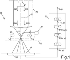
- Figure 1 shows an exemplary embodiment of an apparatus 10 for time-resolved interferometric measurements.
- the apparatus 10 may form or be comprised by an electron holography system.
- the apparatus 10 comprises a source 20 for generating two coherent electron waves, which are hereinafter referred to as reference wave RW and object wave OW.
- the source 20 comprises an electron emitter 21 which emits a first partial electron wave W1 and a second partial electron wave W2.
- the first partial electron wave W1 is transmitted through vacuum and forms the reference wave RW.
- the second partial electron wave W2, which is coherent with the first partial electron wave W1, passes an object 22 and forms the object wave OW.
- the reference wave RW and the object wave OW passes an objective 30 and an overlap device 40.
- the overlap device 40 overlaps the reference wave RW and the object wave OW and produces an interference pattern IP that is measured by a measurement device 50.
- Each measurement cycle lasts a given exposure time T and generates measured interference values I(x,y) in case of a two-dimensional interference pattern.
- the overlap device 40 is a biprism comprising a filament 41 that is bracketed by two counter electrodes 42 and 43.
- the filament 41 is on a first electrostatic potential.
- the two counter electrodes 42 and 43 are on electrostatic potentials that are different from the first electrostatic potential.
- the two counter electrodes 42 and 43 can be on ground potential, whereas the first electrostatic potential may be positive potential relative to ground potential.
- the apparatus 10 further comprises a temporal interference switch or gate 60.
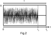
- the temporal interference switch or gate 60 disturbs or destroys the interference pattern IP in at least one time segment, hereinafter referred to as disturbed time segment [0, t1] (see Figure 2 ), of the given exposure time T such that the corresponding measured interference values I(x,y) describe a disturbed or destroyed interference pattern IP.
- the temporal interference switch or gate 60 disturbs the interference pattern IP less or leaves it undisturbed.
- the temporal interference switch or gate 60 may be a mechanical device which mechanically moves the apparatus or parts thereof and thereby influences the interference pattern IP mechanically.
- the temporal interference switch or gate 60 is formed by the overlap device 40 and a noise generator 61 which controls the overlap device 40 via a control signal S.
- the control signal S may be a voltage signal that modulates the electric potential of the filament 41.
- the control signal S is depicted in Figure 2 versus time in an exemplary fashion.
- the noise generator 61 applies an electric noise signal to the filament 41 such that the electrostatic potential of the filament is unstable and the overlap functionality of the biprism is jeopardized.
- the noise generator does not apply noise to the filament 41 and the biprism can overlap the waves RW and OW and generate the interference pattern IP in the usual way.
- the apparatus 10 comprises an analyzer 70 for analyzing the measured interference values I(x,y) and extracting amplitude and/or phase information from the measured interference values I(x,y).
- the analyzer according to the exemplary embodiment of Figure 1 comprises a Fourier unit 71, a Fourier space filter unit 72, an inverse Fourier unit 73 and an extraction unit 74.
- the Fourier unit 71 subjects the sequence of interference values I(x,y) that were measured during the entire given exposure time T, to a Fourier analysis and calculates transformed values F(I(x,y)) in the Fourier space.
- Figure 3 shows an exemplary distribution of the transformed values F(I(x,y)) in the Fourier space.
- the transformed values F(I(x,y)) form two side bands SB1 and SB2 in the Fourier space.
- the two side bands SB1 and SB2 are arranged symmetrically with respect to a central band ZB.
- the two side bands SB1 and SB2 correspond to the undisturbed time segment [t1, t2] (see Figure 2 ), in which the temporal interference switch or gate 60 does not destroy the interference pattern IP.
- the other areas outside the sidebands SB1 and SB2 are influenced by the noise which is applied to the filament 61 during the disturbed time segment [0, t1].
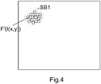
- the Fourier space filter unit 72 selects one of the side bands SB1 or SB2 of the transformed values in the Fourier space.
- the selection may be based on image recognition methods or neural networks known in the art.
- Figure 4 shows the selected side band SB1 in the Fourier space after the selection process.
- the transformed values of the selected side band SB1 are designated by reference numeral F'(I(x,y)).
- the selection of the side band SB1 corresponds to filtering the measured interference values that were measured during the entire given exposure time T, wherein those interference values that were measured during the disturbed time segment [0, t1] are reduced, suppressed or discarded.
- the inverse Fourier unit 73 subjects the transformed values F'(I(x,y)) of the selected side band SB1 to an inverse Fourier analysis and thereby forms filtered interference values I'(x,y)).
- the extraction unit 74 extracts amplitude and/or phase information A, ⁇ from the filtered interference values I'(x,y).
- the present invention is not limited to electron holography systems.
- the present invention may also be used in systems which are based on other types of coherent waves such as, for instance, coherent electromagnetic waves, coherent pressure waves (e.g. coherent acoustic or water waves) or other types of coherent particle waves.
Landscapes
- Physics & Mathematics (AREA)
- General Physics & Mathematics (AREA)
- Chemical & Material Sciences (AREA)
- Analytical Chemistry (AREA)
- Engineering & Computer Science (AREA)
- Computing Systems (AREA)
- Theoretical Computer Science (AREA)
- Analysing Materials By The Use Of Radiation (AREA)
- Measurement Of The Respiration, Hearing Ability, Form, And Blood Characteristics Of Living Organisms (AREA)
- Investigating Or Analysing Materials By Optical Means (AREA)
- Investigating Or Analysing Materials By The Use Of Chemical Reactions (AREA)
- Measurement Of Radiation (AREA)
Priority Applications (4)
| Application Number | Priority Date | Filing Date | Title |
|---|---|---|---|
| EP17160812.8A EP3376522A1 (de) | 2017-03-14 | 2017-03-14 | Verfahren und vorrichtung zur durchführung einer zeitaufgelösten interferometrischen messung |
| PCT/EP2018/054806 WO2018166786A1 (en) | 2017-03-14 | 2018-02-27 | Method and apparatus for carrying out a time-resolved interferometric measurement |
| US16/493,610 US11293747B2 (en) | 2017-03-14 | 2018-02-27 | Method and apparatus for carrying out a time-resolved interferometric measurement |
| TW107108251A TWI786094B (zh) | 2017-03-14 | 2018-03-12 | 進行時間解析干涉測量方法及裝置 |
Applications Claiming Priority (1)
| Application Number | Priority Date | Filing Date | Title |
|---|---|---|---|
| EP17160812.8A EP3376522A1 (de) | 2017-03-14 | 2017-03-14 | Verfahren und vorrichtung zur durchführung einer zeitaufgelösten interferometrischen messung |
Publications (1)
| Publication Number | Publication Date |
|---|---|
| EP3376522A1 true EP3376522A1 (de) | 2018-09-19 |
Family
ID=58398016
Family Applications (1)
| Application Number | Title | Priority Date | Filing Date |
|---|---|---|---|
| EP17160812.8A Pending EP3376522A1 (de) | 2017-03-14 | 2017-03-14 | Verfahren und vorrichtung zur durchführung einer zeitaufgelösten interferometrischen messung |
Country Status (4)
| Country | Link |
|---|---|
| US (1) | US11293747B2 (de) |
| EP (1) | EP3376522A1 (de) |
| TW (1) | TWI786094B (de) |
| WO (1) | WO2018166786A1 (de) |
Cited By (2)
| Publication number | Priority date | Publication date | Assignee | Title |
|---|---|---|---|---|
| CN110108643A (zh) * | 2019-04-16 | 2019-08-09 | 北京遥测技术研究所 | 一种用于光声检测的干涉条纹相位提取方法 |
| EP4513526A1 (de) | 2023-08-25 | 2025-02-26 | Technische Universität Berlin | Vorrichtung zur durchführung einer interferometrischen messung |
Citations (2)
| Publication number | Priority date | Publication date | Assignee | Title |
|---|---|---|---|---|
| US20030227658A1 (en) * | 1997-06-11 | 2003-12-11 | Thomas Clarence E. | Spatially-heterodyned holography |
| EP1426998A2 (de) * | 2002-11-20 | 2004-06-09 | Nagoya University | Transmissionselektronenmikroskop und Verfahren zur dreidimensionalen Beobachtung |
Family Cites Families (5)
| Publication number | Priority date | Publication date | Assignee | Title |
|---|---|---|---|---|
| TWI346767B (en) * | 2006-09-27 | 2011-08-11 | Verity Instr Inc | Self referencing heterodyne reflectometer and heterodyne reflectometer for measuring thickness of a target layer deposed on a substrate |
| CN103267478B (zh) * | 2013-04-08 | 2018-10-02 | 辽宁科旺光电科技有限公司 | 高精度位置检测装置及方法 |
| CN103267482A (zh) * | 2013-04-08 | 2013-08-28 | 辽宁科旺光电科技有限公司 | 一种高精度位移检测装置及方法 |
| CN104535199B (zh) * | 2015-01-09 | 2018-01-12 | 电子科技大学 | 一种相干测量太赫兹波频率的方法 |
| CN111615667A (zh) * | 2018-01-17 | 2020-09-01 | Asml荷兰有限公司 | 测量目标的方法和量测设备 |
-
2017
- 2017-03-14 EP EP17160812.8A patent/EP3376522A1/de active Pending
-
2018
- 2018-02-27 US US16/493,610 patent/US11293747B2/en active Active
- 2018-02-27 WO PCT/EP2018/054806 patent/WO2018166786A1/en not_active Ceased
- 2018-03-12 TW TW107108251A patent/TWI786094B/zh active
Patent Citations (2)
| Publication number | Priority date | Publication date | Assignee | Title |
|---|---|---|---|---|
| US20030227658A1 (en) * | 1997-06-11 | 2003-12-11 | Thomas Clarence E. | Spatially-heterodyned holography |
| EP1426998A2 (de) * | 2002-11-20 | 2004-06-09 | Nagoya University | Transmissionselektronenmikroskop und Verfahren zur dreidimensionalen Beobachtung |
Non-Patent Citations (3)
| Title |
|---|
| FEIST ARMIN ET AL: "Ultrafast transmission electron microscopy using a laser-driven field emitter: Femtosecond resolution with a high coherence electron beam", ULTRAMICROSCOPY, vol. 176, 11 December 2016 (2016-12-11), pages 63 - 73, XP029976468, ISSN: 0304-3991, DOI: 10.1016/J.ULTRAMIC.2016.12.005 * |
| PETITGRAND S ET AL: "3D measurement of micromechanical device vibration mode shapes with a stroboscopic interferometric microscope", OPTICS AND LASERS IN ENGINEERING, ELSEVIER, AMSTERDAM, NL, vol. 36, no. 2, 1 August 2001 (2001-08-01), pages 77 - 101, XP002574894, ISSN: 0143-8166, DOI: 10.1016/S0143-8166(01)00040-9 * |
| REED B W ET AL: "The Evolution of Ultrafast Electron Microscope Instrumentation", MICROSCOPY AND MICROANALYSIS,, vol. 15, no. 4, 1 August 2009 (2009-08-01), pages 272 - 281, XP001523798, ISSN: 1431-9276, DOI: 10.1017/S1431927609090394 * |
Cited By (3)
| Publication number | Priority date | Publication date | Assignee | Title |
|---|---|---|---|---|
| CN110108643A (zh) * | 2019-04-16 | 2019-08-09 | 北京遥测技术研究所 | 一种用于光声检测的干涉条纹相位提取方法 |
| CN110108643B (zh) * | 2019-04-16 | 2021-12-07 | 北京遥测技术研究所 | 一种用于光声检测的干涉条纹相位提取方法 |
| EP4513526A1 (de) | 2023-08-25 | 2025-02-26 | Technische Universität Berlin | Vorrichtung zur durchführung einer interferometrischen messung |
Also Published As
| Publication number | Publication date |
|---|---|
| TWI786094B (zh) | 2022-12-11 |
| WO2018166786A1 (en) | 2018-09-20 |
| US20200103213A1 (en) | 2020-04-02 |
| TW201833521A (zh) | 2018-09-16 |
| US11293747B2 (en) | 2022-04-05 |
Similar Documents
| Publication | Publication Date | Title |
|---|---|---|
| JP6508336B2 (ja) | フーリエ変換質量分析法 | |
| JP6555428B2 (ja) | イメージ電荷/電流信号の処理方法 | |
| JP4875696B2 (ja) | 電磁気的な多チャネル測定において干渉を抑制するための方法及び装置 | |
| US11293747B2 (en) | Method and apparatus for carrying out a time-resolved interferometric measurement | |
| Wang et al. | Feature extraction and classification of load dynamic characteristics based on lifting wavelet packet transform in power system load modeling | |
| Jia et al. | Time–frequency-based non-harmonic analysis to reduce line-noise impact for LIGO observation system | |
| Kim et al. | Effective band-selection algorithm for rolling element bearing diagnosis using AE sensor data under noisy conditions: SJ Kim et al. | |
| US4788495A (en) | Method for the indirect identification of the intensity distribution of particle beam pulses generated in a particle beam measuring instrument | |
| Moughty et al. | Evaluation of the Hilbert Huang transformation of transient signals for bridge condition assessment | |
| DE60006393T2 (de) | Korrelations-analyse im phasenbereich | |
| EP4539090A1 (de) | Korrektur von optischen aberrationen in der ladungsträgerstrahlmikroskopie | |
| Wei | Instantaneous frequency extraction in time-varying structures using a maximum gradient method | |
| JP6817628B2 (ja) | 加振レーダ装置及びデータ解析装置 | |
| EP4306972A1 (de) | Inspektionsvorrichtung und inspektionsverfahren | |
| Gao et al. | A Method Using EEMD and L-Kurtosis to detect faults in roller bearings | |
| US20250069842A1 (en) | Techniques for waveform detection of periodic signals using voltage contrast | |
| US11508550B2 (en) | Method and apparatus for image processing | |
| Grüttner et al. | System matrices for field of view patches in magnetic particle imaging | |
| JPH1054825A (ja) | 電磁誘導試験評価方法及び装置 | |
| CN112534358B (zh) | 用于基于电子全息术检测测量值的设备和方法 | |
| Stein et al. | Simultaneous Estimation of Multiple Backbone Curves Using Smooth Coordinate Tracking | |
| Li et al. | Sound source localization of speed reducer with discontinuity of time–frequency energy distribution under non-stationary operating conditions | |
| CN119085747A (zh) | 一种电场下的绝缘油运动状态观察方法及系统 | |
| Koleva et al. | Signal formation analysis of the electron beam current distribution measurements | |
| Pavlov et al. | Development of a Beam Diagnostics Method Based on Pick-Up Electrode Signal Analysis: Bench Test Results |
Legal Events
| Date | Code | Title | Description |
|---|---|---|---|
| PUAI | Public reference made under article 153(3) epc to a published international application that has entered the european phase |
Free format text: ORIGINAL CODE: 0009012 |
|
| STAA | Information on the status of an ep patent application or granted ep patent |
Free format text: STATUS: THE APPLICATION HAS BEEN PUBLISHED |
|
| AK | Designated contracting states |
Kind code of ref document: A1 Designated state(s): AL AT BE BG CH CY CZ DE DK EE ES FI FR GB GR HR HU IE IS IT LI LT LU LV MC MK MT NL NO PL PT RO RS SE SI SK SM TR |
|
| AX | Request for extension of the european patent |
Extension state: BA ME |
|
| STAA | Information on the status of an ep patent application or granted ep patent |
Free format text: STATUS: REQUEST FOR EXAMINATION WAS MADE |
|
| 17P | Request for examination filed |
Effective date: 20190312 |
|
| RBV | Designated contracting states (corrected) |
Designated state(s): AL AT BE BG CH CY CZ DE DK EE ES FI FR GB GR HR HU IE IS IT LI LT LU LV MC MK MT NL NO PL PT RO RS SE SI SK SM TR |
|
| STAA | Information on the status of an ep patent application or granted ep patent |
Free format text: STATUS: EXAMINATION IS IN PROGRESS |
|
| 17Q | First examination report despatched |
Effective date: 20210414 |
|
| GRAP | Despatch of communication of intention to grant a patent |
Free format text: ORIGINAL CODE: EPIDOSNIGR1 |
|
| STAA | Information on the status of an ep patent application or granted ep patent |
Free format text: STATUS: GRANT OF PATENT IS INTENDED |
|
| RIC1 | Information provided on ipc code assigned before grant |
Ipc: H01J 37/26 20060101AFI20260126BHEP Ipc: G01B 9/021 20060101ALI20260126BHEP Ipc: G03H 1/04 20060101ALI20260126BHEP Ipc: G03H 5/00 20060101ALI20260126BHEP |
|
| INTG | Intention to grant announced |
Effective date: 20260303 |