EP3376507A1 - Ceramic scintillator array, method for manufacturing same, radiation detector and radiation detection device - Google Patents
Ceramic scintillator array, method for manufacturing same, radiation detector and radiation detection device Download PDFInfo
- Publication number
- EP3376507A1 EP3376507A1 EP16864298.1A EP16864298A EP3376507A1 EP 3376507 A1 EP3376507 A1 EP 3376507A1 EP 16864298 A EP16864298 A EP 16864298A EP 3376507 A1 EP3376507 A1 EP 3376507A1
- Authority
- EP
- European Patent Office
- Prior art keywords
- scintillator array
- transparent resin
- ceramic scintillator
- ceramic
- array according
- Prior art date
- Legal status (The legal status is an assumption and is not a legal conclusion. Google has not performed a legal analysis and makes no representation as to the accuracy of the status listed.)
- Granted
Links
- 239000000919 ceramic Substances 0.000 title claims abstract description 81
- 230000005855 radiation Effects 0.000 title claims description 48
- 238000000034 method Methods 0.000 title claims description 13
- 238000004519 manufacturing process Methods 0.000 title claims description 9
- 238000001514 detection method Methods 0.000 title description 15
- 229920005989 resin Polymers 0.000 claims abstract description 54
- 239000011347 resin Substances 0.000 claims abstract description 54
- 239000002245 particle Substances 0.000 claims abstract description 45
- 230000009477 glass transition Effects 0.000 claims abstract description 26
- 229910052761 rare earth metal Inorganic materials 0.000 claims abstract description 23
- UAHZTKVCYHJBJQ-UHFFFAOYSA-N [P].S=O Chemical compound [P].S=O UAHZTKVCYHJBJQ-UHFFFAOYSA-N 0.000 claims abstract description 14
- 150000002910 rare earth metals Chemical class 0.000 claims abstract description 14
- MCMNRKCIXSYSNV-UHFFFAOYSA-N Zirconium dioxide Chemical compound O=[Zr]=O MCMNRKCIXSYSNV-UHFFFAOYSA-N 0.000 claims abstract description 10
- GWEVSGVZZGPLCZ-UHFFFAOYSA-N Titan oxide Chemical compound O=[Ti]=O GWEVSGVZZGPLCZ-UHFFFAOYSA-N 0.000 claims abstract description 9
- VYPSYNLAJGMNEJ-UHFFFAOYSA-N Silicium dioxide Chemical compound O=[Si]=O VYPSYNLAJGMNEJ-UHFFFAOYSA-N 0.000 claims abstract description 7
- OGIDPMRJRNCKJF-UHFFFAOYSA-N titanium oxide Inorganic materials [Ti]=O OGIDPMRJRNCKJF-UHFFFAOYSA-N 0.000 claims abstract description 7
- 239000000126 substance Substances 0.000 claims abstract description 6
- PNEYBMLMFCGWSK-UHFFFAOYSA-N aluminium oxide Inorganic materials [O-2].[O-2].[O-2].[Al+3].[Al+3] PNEYBMLMFCGWSK-UHFFFAOYSA-N 0.000 claims abstract description 5
- 239000000377 silicon dioxide Substances 0.000 claims abstract description 3
- 238000007689 inspection Methods 0.000 claims description 29
- 230000007423 decrease Effects 0.000 claims description 25
- 230000008859 change Effects 0.000 claims description 22
- 239000000203 mixture Substances 0.000 claims description 14
- 239000003822 epoxy resin Substances 0.000 claims description 13
- 229920000647 polyepoxide Polymers 0.000 claims description 13
- 239000000463 material Substances 0.000 claims description 11
- 239000012190 activator Substances 0.000 claims description 7
- 238000009826 distribution Methods 0.000 claims description 6
- 229910052688 Gadolinium Inorganic materials 0.000 claims description 4
- 229910052765 Lutetium Inorganic materials 0.000 claims description 4
- 125000001931 aliphatic group Chemical group 0.000 claims description 4
- 229910052746 lanthanum Inorganic materials 0.000 claims description 4
- 229910052727 yttrium Inorganic materials 0.000 claims description 4
- 238000002834 transmittance Methods 0.000 claims description 3
- FPMWYYKZGBBCRR-UHFFFAOYSA-N [P].O=S.[Gd] Chemical compound [P].O=S.[Gd] FPMWYYKZGBBCRR-UHFFFAOYSA-N 0.000 claims description 2
- 230000000052 comparative effect Effects 0.000 description 12
- 239000011342 resin composition Substances 0.000 description 11
- OAICVXFJPJFONN-UHFFFAOYSA-N Phosphorus Chemical compound [P] OAICVXFJPJFONN-UHFFFAOYSA-N 0.000 description 10
- 238000006243 chemical reaction Methods 0.000 description 10
- 238000003491 array Methods 0.000 description 9
- 238000003860 storage Methods 0.000 description 7
- 230000008569 process Effects 0.000 description 6
- 238000005259 measurement Methods 0.000 description 5
- 238000012545 processing Methods 0.000 description 5
- -1 rare earth oxysulfide Chemical class 0.000 description 5
- 238000003745 diagnosis Methods 0.000 description 4
- LNEPOXFFQSENCJ-UHFFFAOYSA-N haloperidol Chemical compound C1CC(O)(C=2C=CC(Cl)=CC=2)CCN1CCCC(=O)C1=CC=C(F)C=C1 LNEPOXFFQSENCJ-UHFFFAOYSA-N 0.000 description 4
- 238000010438 heat treatment Methods 0.000 description 4
- 230000035945 sensitivity Effects 0.000 description 4
- 238000010521 absorption reaction Methods 0.000 description 3
- 238000001816 cooling Methods 0.000 description 3
- 230000001066 destructive effect Effects 0.000 description 3
- 230000000694 effects Effects 0.000 description 3
- 239000012535 impurity Substances 0.000 description 3
- 239000000843 powder Substances 0.000 description 3
- XKRFYHLGVUSROY-UHFFFAOYSA-N Argon Chemical compound [Ar] XKRFYHLGVUSROY-UHFFFAOYSA-N 0.000 description 2
- 229910019142 PO4 Inorganic materials 0.000 description 2
- 229910052777 Praseodymium Inorganic materials 0.000 description 2
- 239000011248 coating agent Substances 0.000 description 2
- 238000000576 coating method Methods 0.000 description 2
- 230000003247 decreasing effect Effects 0.000 description 2
- 230000006866 deterioration Effects 0.000 description 2
- 230000006872 improvement Effects 0.000 description 2
- PUDIUYLPXJFUGB-UHFFFAOYSA-N praseodymium atom Chemical compound [Pr] PUDIUYLPXJFUGB-UHFFFAOYSA-N 0.000 description 2
- 238000005245 sintering Methods 0.000 description 2
- 239000007787 solid Substances 0.000 description 2
- 238000006467 substitution reaction Methods 0.000 description 2
- 230000001629 suppression Effects 0.000 description 2
- 230000002123 temporal effect Effects 0.000 description 2
- 229910052684 Cerium Inorganic materials 0.000 description 1
- KRHYYFGTRYWZRS-UHFFFAOYSA-M Fluoride anion Chemical compound [F-] KRHYYFGTRYWZRS-UHFFFAOYSA-M 0.000 description 1
- 241001465754 Metazoa Species 0.000 description 1
- 229910052786 argon Inorganic materials 0.000 description 1
- 239000002775 capsule Substances 0.000 description 1
- 239000003795 chemical substances by application Substances 0.000 description 1
- 230000003081 coactivator Effects 0.000 description 1
- 230000008602 contraction Effects 0.000 description 1
- 238000005520 cutting process Methods 0.000 description 1
- 238000000280 densification Methods 0.000 description 1
- 238000013461 design Methods 0.000 description 1
- 230000002542 deteriorative effect Effects 0.000 description 1
- 238000011156 evaluation Methods 0.000 description 1
- UIWYJDYFSGRHKR-UHFFFAOYSA-N gadolinium atom Chemical compound [Gd] UIWYJDYFSGRHKR-UHFFFAOYSA-N 0.000 description 1
- 239000007789 gas Substances 0.000 description 1
- 239000004922 lacquer Substances 0.000 description 1
- FZLIPJUXYLNCLC-UHFFFAOYSA-N lanthanum atom Chemical compound [La] FZLIPJUXYLNCLC-UHFFFAOYSA-N 0.000 description 1
- OHSVLFRHMCKCQY-UHFFFAOYSA-N lutetium atom Chemical compound [Lu] OHSVLFRHMCKCQY-UHFFFAOYSA-N 0.000 description 1
- 239000011159 matrix material Substances 0.000 description 1
- 238000012986 modification Methods 0.000 description 1
- 230000004048 modification Effects 0.000 description 1
- 239000010452 phosphate Substances 0.000 description 1
- 229910052698 phosphorus Inorganic materials 0.000 description 1
- 238000003825 pressing Methods 0.000 description 1
- 238000007711 solidification Methods 0.000 description 1
- 230000008023 solidification Effects 0.000 description 1
- XTQHKBHJIVJGKJ-UHFFFAOYSA-N sulfur monoxide Chemical class S=O XTQHKBHJIVJGKJ-UHFFFAOYSA-N 0.000 description 1
- 229920001187 thermosetting polymer Polymers 0.000 description 1
- 230000007704 transition Effects 0.000 description 1
- VWQVUPCCIRVNHF-UHFFFAOYSA-N yttrium atom Chemical compound [Y] VWQVUPCCIRVNHF-UHFFFAOYSA-N 0.000 description 1
- 229910052726 zirconium Inorganic materials 0.000 description 1
Images

Classifications
-
- G—PHYSICS
- G01—MEASURING; TESTING
- G01T—MEASUREMENT OF NUCLEAR OR X-RADIATION
- G01T1/00—Measuring X-radiation, gamma radiation, corpuscular radiation, or cosmic radiation
- G01T1/16—Measuring radiation intensity
- G01T1/20—Measuring radiation intensity with scintillation detectors
- G01T1/2002—Optical details, e.g. reflecting or diffusing layers
-
- A—HUMAN NECESSITIES
- A61—MEDICAL OR VETERINARY SCIENCE; HYGIENE
- A61B—DIAGNOSIS; SURGERY; IDENTIFICATION
- A61B6/00—Apparatus for radiation diagnosis, e.g. combined with radiation therapy equipment
- A61B6/02—Devices for diagnosis sequentially in different planes; Stereoscopic radiation diagnosis
- A61B6/03—Computerised tomographs
- A61B6/032—Transmission computed tomography [CT]
-
- A—HUMAN NECESSITIES
- A61—MEDICAL OR VETERINARY SCIENCE; HYGIENE
- A61B—DIAGNOSIS; SURGERY; IDENTIFICATION
- A61B6/00—Apparatus for radiation diagnosis, e.g. combined with radiation therapy equipment
- A61B6/42—Apparatus for radiation diagnosis, e.g. combined with radiation therapy equipment with arrangements for detecting radiation specially adapted for radiation diagnosis
- A61B6/4208—Apparatus for radiation diagnosis, e.g. combined with radiation therapy equipment with arrangements for detecting radiation specially adapted for radiation diagnosis characterised by using a particular type of detector
-
- G—PHYSICS
- G01—MEASURING; TESTING
- G01T—MEASUREMENT OF NUCLEAR OR X-RADIATION
- G01T1/00—Measuring X-radiation, gamma radiation, corpuscular radiation, or cosmic radiation
- G01T1/16—Measuring radiation intensity
- G01T1/20—Measuring radiation intensity with scintillation detectors
-
- G—PHYSICS
- G01—MEASURING; TESTING
- G01T—MEASUREMENT OF NUCLEAR OR X-RADIATION
- G01T1/00—Measuring X-radiation, gamma radiation, corpuscular radiation, or cosmic radiation
- G01T1/16—Measuring radiation intensity
- G01T1/20—Measuring radiation intensity with scintillation detectors
- G01T1/202—Measuring radiation intensity with scintillation detectors the detector being a crystal
- G01T1/2023—Selection of materials
-
- G—PHYSICS
- G01—MEASURING; TESTING
- G01T—MEASUREMENT OF NUCLEAR OR X-RADIATION
- G01T7/00—Details of radiation-measuring instruments
-
- G—PHYSICS
- G21—NUCLEAR PHYSICS; NUCLEAR ENGINEERING
- G21K—TECHNIQUES FOR HANDLING PARTICLES OR IONISING RADIATION NOT OTHERWISE PROVIDED FOR; IRRADIATION DEVICES; GAMMA RAY OR X-RAY MICROSCOPES
- G21K4/00—Conversion screens for the conversion of the spatial distribution of X-rays or particle radiation into visible images, e.g. fluoroscopic screens
-
- C—CHEMISTRY; METALLURGY
- C09—DYES; PAINTS; POLISHES; NATURAL RESINS; ADHESIVES; COMPOSITIONS NOT OTHERWISE PROVIDED FOR; APPLICATIONS OF MATERIALS NOT OTHERWISE PROVIDED FOR
- C09K—MATERIALS FOR MISCELLANEOUS APPLICATIONS, NOT PROVIDED FOR ELSEWHERE
- C09K11/00—Luminescent, e.g. electroluminescent, chemiluminescent materials
- C09K11/08—Luminescent, e.g. electroluminescent, chemiluminescent materials containing inorganic luminescent materials
- C09K11/77—Luminescent, e.g. electroluminescent, chemiluminescent materials containing inorganic luminescent materials containing rare earth metals
- C09K11/7713—Sulfates
-
- G—PHYSICS
- G21—NUCLEAR PHYSICS; NUCLEAR ENGINEERING
- G21K—TECHNIQUES FOR HANDLING PARTICLES OR IONISING RADIATION NOT OTHERWISE PROVIDED FOR; IRRADIATION DEVICES; GAMMA RAY OR X-RAY MICROSCOPES
- G21K4/00—Conversion screens for the conversion of the spatial distribution of X-rays or particle radiation into visible images, e.g. fluoroscopic screens
- G21K2004/06—Conversion screens for the conversion of the spatial distribution of X-rays or particle radiation into visible images, e.g. fluoroscopic screens with a phosphor layer
Definitions
- Embodiments described herein generally relate to a ceramic scintillator array and a method for manufacturing the same, a radiation detector, and a radiation inspection device.
- the X-ray CT scanner is composed of an X-ray tube (X-ray source) emitting a fan beam X-ray in a fan shape and an X-ray detector including many X-ray detection elements, the X-ray tube and the X-ray detector being arranged opposed each other with a tomographic surface of an inspection target set as a middle.
- X-ray CT scanner is composed of an X-ray tube (X-ray source) emitting a fan beam X-ray in a fan shape and an X-ray detector including many X-ray detection elements, the X-ray tube and the X-ray detector being arranged opposed each other with a tomographic surface of an inspection target set as a middle.
- the X-ray tube emits the fan beam X-ray while rotating with respect to the inspection target, and the X-ray detector collects absorption data on X-ray transmitted through the inspection target. Thereafter, the X-ray absorption data is analyzed by a computer, whereby a tomogram is reproduced.
- a detection element using a solid scintillator is widely used. In the radiation detector including the detection element using the solid scintillator, it is to easy to increase the number of channels by downsizing the detection element, thus further increasing the resolution of the X-ray CT scanner and the like.
- the radiation inspection device such as the X-ray CT scanner is used in various fields for medical purpose, industrial purpose and so on.
- the X-ray CT scanner for example, there is a known device of a multi-splice type in which detection elements such as photodiodes are vertically and horizontally arranged in two dimensions and a scintillator array is mounted thereon.
- the radiation detector mounted in the radiation inspection device includes detection elements arranged in a plurality of vertical and horizontal lines, and each of the detection elements is provided with a scintillator segment.
- the X-ray incident on the scintillator segment is converted into visible light, and the detection element converts the visible light into an electric signal to image it.
- the detection element is downsized and the pitch between adjacent detection elements is reduced. Accompanying the above, the size of the scintillator segment is also reduced.
- a rare earth oxysulfide-based phosphor ceramics is high in light emission efficiency and has preferable characteristics for use in the scintillator segment. Therefore, a radiation detector is becoming widely used which is made by combining a ceramic scintillator segment processed by cutout process or grooving process from a sintered compact (ingot) of the rare earth oxysulfide-based phosphor ceramics being the scintillator material and a photodiode as the detection element.
- the scintillator using the phosphor ceramics there is a known ceramic scintillator composed of a sintered compact of, for example, a gadolinium oxysulfide phosphor.
- the ceramic scintillator array is fabricated as follows for instance. First, the rare earth oxysulfide-based phosphor powder being the scintillator material is molded into a suitable shape, and the molded powder is sintered into a sintered compact (ingot). The sintered compact of the scintillator material is subjected to a cutting process such as cutout process or grooving process to form scintillator segments corresponding to the plurality of detection elements. Further, a reflective layer is formed between the scintillator segments to integrate them, thereby fabricating a scintillator array.
- the dimensional accuracy of the ceramic scintillator array affects the resolution of a CT diagnostic image.
- a temperature of 50°C at maximum is applied to the radiation detector mounted on the X-ray CT scanner.
- expansion of the reflective layer due to heating and contraction due to a decrease in temperature occur to cause a small dimensional change between adjacent scintillator segments, namely, pitch shift of the segment, warpage of the scintillator array, variation in outside dimension and so on. These become a cause of deteriorating the resolution of the diagnostic image of the radiation detector.
- the radiation detector mounted on the X-ray CT scanner is exposed to an X-ray during operation.
- the resin contained in the reflective layer constituting the scintillator array changes in color, resulting in decreased light output.
- the thermal expansion rate of the resin contained in the reflective layer of the scintillator array fluctuates under the influence of the temperature and humidity, resulting in occurrence of the dimensional change of the scintillator array such as pitch shift of the segment, warpage of the scintillator array, variation in outside dimension and so on.
- a problem to be solved by the present invention is to provide a ceramic scintillator array and a method for manufacturing the same, which can suppress change in pitch and outside dimension of a segment and decrease in dimensional accuracy and variation in dimensional accuracy due to warpage or the like to cope with downsizing of a radiation detector and the like while maintaining excellent light output. Further, another problem is to provide a radiation detector and a radiation inspection device which increase the resolution and image accuracy by using the ceramic scintillator array to thereby improve the medical diagnosis performance and the non-destructive inspection accuracy.
- a ceramic scintillator array of an embodiment includes: a plurality of scintillator segments each composed of a sintered compact of a rare earth oxysulfide phosphor; and a reflective layer interposed between the scintillator segments adjacent to each other in a manner to integrate the plurality of scintillator segments.
- the reflective layer contains a transparent resin and reflective particles dispersed in the transparent resin.
- the reflective particles contain titanium oxide and at least one inorganic substance selected from the group consisting of alumina, zirconia, and silica.
- a glass transition point of the transparent resin is 50°C or higher, and a thermal expansion coefficient of the transparent resin at a temperature higher than the glass transition point is 3.5 ⁇ 10 -5 /°C or less.
- Fig. 1 is a cross-sectional view illustrating a ceramic scintillator array of an embodiment
- Fig. 2 is a plan view illustrating the ceramic scintillator array of the embodiment.
- 1 denote a scintillator array
- 2 denotes a scintillator segment
- 3 denotes a reflective layer.
- the scintillator array 1 has a plurality of scintillator segments 2. Between adjacent scintillator segments 2, the reflective layer 3 is interposed. The reflective layer 3 is bonded to each of the adjacent scintillator segments 2.
- the plurality of scintillator segments 2 are integrated by the reflective layers 3 bonded to them.
- the scintillator array 1 has a structure in which the plurality of scintillator segments 2 are integrated by the reflective layers 3.
- the scintillator array 1 may have any one of a structure in which the plurality of scintillator segments 2 are arranged in a line and a structure in which the plurality of scintillator segments 2 are arranged in two dimensions with a predetermined number of the scintillator segments 2 arranged each in a vertical direction and a horizontal direction as illustrated in Fig. 2 .
- the reflective layer 3 is provided between the scintillator segments 2 in each of the vertical direction and the horizontal direction.
- the number of scintillator segments 2 is appropriately set according to the structure, resolution or the like of the radiation detector such as an X-ray detector.
- the scintillator segment 2 is composed of a sintered compact of a rare earth oxysulfide phosphor.
- a rare earth oxysulfide phosphor ceramics is a rare earth oxysulfide phosphor containing praseodymium (Pr) as an activator.
- Pr praseodymium
- Examples of the rare earth oxysulfide constituting a phosphor ceramics include oxysulfides of rare earth elements such as yttrium (Y), gadolinium (Gd), lanthanum (La), lutetium (Lu) and so on.
- the scintillator segment 2 in the ceramic scintillator array 1 of the embodiment is preferably composed of a rare earth oxysulfide phosphor ceramics (scintillator material) having a composition expressed by general formula: RE 2 O 2 S:Pr ... (1) where RE is at least one element selected from the group consisting of Y, Gd, La, and Lu.
- RE is at least one element selected from the group consisting of Y, Gd, La, and Lu.
- Gd in particular, of the above-described rare earth elements has a large X-ray absorption coefficient and contributes to improvement in light output of the ceramic scintillator array 1. Accordingly, it is more preferable to use Gd 2 O 2 S:Pr phosphor for the scintillator segment 2 of the embodiment.
- another rare earth element may substitute for a part of Gd. In this case, a substitution amount of another rare earth element for Gd is preferably set to 10 mol% or less.
- the rare earth oxysulfide phosphor ceramics substantially expressed by general formula: (Gd 1-x , RE' x ) 2 O 2 S:Pr ... (2) where RE' is at least one element selected from the group consisting of Y, La, and Lu, and x is a number of atomic ratio satisfying 0 ⁇ x ⁇ 0.1.
- the rare earth oxysulfide phosphor ceramics (scintillator material) is used as the activator that increases light output of the rare earth oxysulfide phosphor ceramics (scintillator material). Pr can further reduce afterglow or the like as compared with other activators. Accordingly, the rare earth oxysulfide phosphor ceramics (scintillator material) containing Pr as the activator is effective as a fluorescence generating means of the radiation detector.
- the content of Pr in the rare earth oxysulfide phosphor ceramics is preferably set to a range of 0.001 to 10 mol% relative to a phosphor host (for example, RE 2 O 2 S such as Gd 2 O 2 S).
- a phosphor host for example, RE 2 O 2 S such as Gd 2 O 2 S.
- a content of Pr exceeding 10 mol% conversely causes a decrease in light output.
- a content of Pr less than 0.001 mol% fails to provide sufficient effect as a main activator.
- the content of Pr is preferably in a range of 0.01 to 1 mol%.
- a small amount of at least one element selected from the group consisting of Ce, Zr, and P may be contained as a coactivator in addition to Pr as the main activator. These elements exhibit effect to suppression of exposure deterioration, suppression of afterglow and so on.
- the contents of the coactivators are preferably set, as a total amount, to a range of 0.00001 to 0.1 mol% relative to the phosphor host.
- a scintillator sintered compact forming the scintillator segment 2 of the embodiment is preferably composed of a high-purity rare earth oxysulfide-based phosphor ceramics (scintillator material). Since impurities become a cause of a decrease in sensitivity of the scintillator, it is preferable to reduce as much as possible the impurity amount.
- a phosphate radical (PO 4 ) becomes a cause of a decrease in sensitivity, and therefore its content is preferably set to 150 ppm or less. In the case of using fluoride or the like as a sintering aid for densification, the sintering aid remains as an impurity, causing a decrease in sensitivity.
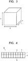
- the scintillator segment 2 is composed of a sintered compact in a cube shape or a rectangular parallelepiped shape, as illustrated in Fig. 3 .
- the volume of the scintillator segment 2 is preferably 1 mm 3 or less. Downsizing the scintillator segment 2 makes it possible to obtain an image to be detected with higher definition.
- Each size of the length (L), breadth (S) and thickness (T) of the scintillator segment 2 is not always limited, but is preferably 1 mm or less.
- the width (W) of the reflective layer 3 can be made smaller to 100 ⁇ m or less, and further to 50 ⁇ m or less.
- the reflective layer 3 that integrates the plurality of scintillator segments 2 contains a transparent resin and reflective particles dispersed in the transparent resin.
- a resin having a glass transition point (transition temperature) of 50°C or higher is used for the transparent resin. Since any of the temperature during process of manufacturing an X-ray CT scanner, the temperature during use of the X-ray CT scanner, and the temperature of a storage environment of the X-ray CT scanner is about 18 to 50°C, it is possible to suppress dimensional change (pitch shift of the segment, warpage of the scintillator array, variation in outside dimension) during manufacturing process, during use, and during storage as long as the glass transition point of the transparent resin is 50°C or higher.
- the glass transition point of the transparent resin constituting the reflective layer 3 is preferably higher than 50°C, more preferably 60°C or higher, and particularly preferably 85°C or higher.
- the thermal expansion coefficient (linear expansion coefficient) at a temperature exceeding the glass transition point of the transparent resin constituting the reflective layer 3 is 3.5 ⁇ 10 -5 /°C or less.
- the thermal expansion coefficient at the temperature exceeding the glass transition point of the transparent resin exceeds 3.5 ⁇ 10 -5 /°C, a change (pitch shift of the segment, warpage of the scintillator array, variation in outside dimension) is likely to occur in finished dimension of the scintillator array due to the temperature during the process of manufacturing the X-ray CT scanner.
- the thermal expansion coefficient at the temperature exceeding the glass transition point of the transparent resin is more preferably 2.5 ⁇ 10 -5 /°C or less.
- the thermal expansion coefficient at a temperature lower the glass transition point of the transparent resin is preferably 2.1 ⁇ 10 -5 /°C or less, and furthermore preferably 1.6 ⁇ 10 -5 /°C or less.
- the transparent resin preferably has a molecular structure including a cyclo structure including no double structure (double bond).
- the glass transition point is likely to become lower than 50°C, and when the scintillator array 1 is exposed to X-ray of an exposure amount corresponding to 10 years operation, the transparent resin changes in color to yellow and the reflective layer 3 becomes likely to decrease in reflectance.
- the decrease in light output of the scintillator array 1 when the initial light output is 100%, the decrease amount possibly exceeds, for example, 25%.
- the transparent resin constituting the reflective layer 3 is preferably an epoxy resin having an aliphatic skeleton. Using the epoxy resin having the aliphatic skeleton makes it easier to satisfy the above-described glass transition point and thermal expansion coefficient at the temperature exceeding the glass transition point. Further, the epoxy resin as the transparent resin preferably has the above-described molecular structure including the cyclo structure. Using the epoxy resin makes it easier to increase the glass transition point and lower the thermal expansion coefficient at the temperature exceeding the glass transition point. In addition, the transparent resin is preferably a room temperature setting two-component epoxy resin.
- the reflective particles dispersed in the transparent resin contain titanium oxide (Ti02) and at least one inorganic substance selected from the group consisting of alumina (Al 2 O 3 ), zirconia (ZrO 2 ), and silica (SiO 2 ).
- Ti02 titanium oxide
- inorganic substance selected from the group consisting of alumina (Al 2 O 3 ), zirconia (ZrO 2 ), and silica (SiO 2 ).
- alumina Al 2 O 3
- ZrO 2 zirconia
- SiO 2 silica
- the reflective particles preferably have a bimodal-type particle size distribution. More specifically, the reflective particles preferably have a particle size distribution having a first particle diameter peak and a second particle diameter peak. Further, it is preferable that in the particle size distribution of the reflective particles, the first particle diameter peak exists in a range of 200 to 350 nm and the second particle diameter peak exists in a range of 750 to 1000 nm. In the case where the particle size distribution of the reflective particles is of a unimodal type, the reflection efficiency of the reflective layer 3 with respect to light having a wavelength of 512 nm becomes more likely to decrease. In contrast to the above, using the reflective particles having the above-described bimodal-type particle size distribution can increase the reflection efficiency of the reflective layer 3. Specifically, the reflection efficiency of the reflective layer 3 with respect to light having a wavelength of 512 nm is preferably 90% or more, with which the variation in light output of the ceramic scintillator array 1 can be reduced.
- the mass ratio of the reflective particles is less than 40%, the reflection efficiency of the reflective layer 3 decreases, and the reflection efficiency of the reflective layer 3 with respect to light having a wavelength of 512 nm is likely to be lower than 90%.
- the mass ratio of the reflective particles exceeds 85%, the reflection efficiency of the reflective layer 3 does not change, but the mass ratio of the transparent resin relatively decreases, resulting in difficulty in stable solidification of the reflective layer 3.
- the change amount in any of pitch, warpage, and outside dimension after the ceramic scintillator array 1 is stored in a packed state for one month in an atmosphere at a temperature of 50°C and a humidity of 80 %RH can be made 0.02 mm or less.
- the temporal dimensional change (pitch shift of the segment, warpage of the scintillator array, variation in outside dimension) of the ceramic scintillator array 1 due to influence of temperature, humidity and so on can be suppressed. Accordingly, the ceramic scintillator array 1 with less variation in light output can be provided.
- the decrease in light output of the ceramic scintillator array 1 due to change in color of the transparent resin can be suppressed.
- the decrease in light output of the ceramic scintillator array 1 by an X-ray exposure amount corresponding to 10 years operation can be made to be within 25%.
- the ceramic scintillator array 1 of the embodiment is manufactured as follows for instance. First, the reflective particles and a resin composition in an uncured state constituting the transparent resin (an uncured material of the transparent resin) are prepared and mixed together to prepare a mixture. Then, a plurality of scintillator segments 2 each processed in a predetermined shape are arranged at regular intervals. The above-described mixture of the reflective particles and the resin composition in the uncured state is applied or filled between adjacent scintillator segments 2.
- the resin composition in the uncured state preferably has a viscosity of 0.2 to 1 Pa•s (200 to 1000 cps).
- the viscosity of the resin composition When the viscosity of the resin composition is less than 0.2 Pa•s, the flowability becomes low, resulting in deterioration of the workability of applying or filling between the scintillator segments 2. When the viscosity of the resin composition exceeds 1 Pa•s, the flowability becomes too high, resulting in a decreased in coating performance or filling performance. Further, the total light transmittance of the transparent resin is preferably 85% or more. When the total light transmittance of the transparent resin is less than 85%, the reflection efficiency of the reflective layer 3 becomes more likely to decrease.
- the mixture of the reflective particles and the resin composition in the uncured state is applied or filled between the plurality of scintillator segments 2 and then the resin composition in the mixture is cured to form the reflective layer 3, thereby bonding and integrating adjacent scintillator segments 2 to manufacture the ceramic scintillator array 1.
- the curing processing of the mixture is appropriately set according to the kinds or the like of the resin composition in the uncured state and a curing agent.
- the curing reaction is promoted by performing thermal processing.
- the curing reaction is promoted by leaving the resin composition stand under room temperature.
- the radiation detector of an embodiment includes the above-described ceramic scintillator array 1 of the embodiment as a fluorescence generating means that emits light according to an incident radiation ray, and further includes a photoelectric conversion means that receives the light from the fluorescence generating means and converts the light output to an electric output.
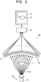
- Fig. 4 illustrates an X-ray detector being one example of the radiation detector of the embodiment.
- An X-ray detector 5 illustrated in Fig. 4 includes the ceramic scintillator array 1 as the fluorescence generating means and a photoelectric conversion element 4 like a photodiode as the photoelectric conversion means.
- the ceramic scintillator array 1 has an X-ray incident surface 1a, and the photoelectric conversion element 4 is integrally mounted on a surface 1b on the opposite side to the X-ray incident surface 1a.
- the photoelectric conversion element 4 for example, a photodiode is used.
- the photoelectric conversion element 4 is arranged to correspond to each of the plurality of scintillator segments 2 constituting the ceramic scintillator array 1. They constitute the radiation detector 5.
- the X-ray incident surface 1a of the ceramic scintillator array 1 may be provided with a surface reflective layer.
- the surface reflective layer is provided not only on the X-ray incident surface 1a of the ceramic scintillator array 1 but may be provided on the mounting surface 1b for mounting the photoelectric conversion element 4. Further, the surface reflective layer may be provided on both the X-ray incident surface 1a and the element mounting surface 1b of the scintillator array 1. Providing the surface reflective layer on the ceramic scintillator array 1 makes it possible to further improve the reflection efficiency with respect to visible light emitted from the scintillator array 1, and accordingly improve the light output of the scintillator array 1.
- the surface reflective layer a mixture of reflective particles and a transparent resin, a lacquer-based coating material or the like is used.
- the mixture of the reflective particles and the transparent resin preferably has the same constitution as that of the reflective layer 3.
- the thickness of the surface reflective layer is preferably in a range of 50 to 250 ⁇ m. When the thickness of the surface reflective layer is less than 50 ⁇ m, sufficient effect of improving the reflection efficiency cannot be obtained. When the thickness of the surface reflective layer exceeds 250 ⁇ m, the X-ray amount transmitted decreases, resulting in a decrease in detection sensitivity.
- the radiation inspection device of an embodiment includes a radiation source that emits a radiation ray toward an inspection target, and a radiation detector that detects the radiation ray transmitted through the inspection target.
- a radiation detector that detects the radiation ray transmitted through the inspection target.
- the above-described radiation detector of the embodiment is used.
- Fig. 5 illustrates an X-ray CT scanner 10 being an example of the radiation inspection device of the embodiment.
- 10 denotes an X-ray CT scanner
- 11 denotes a specimen
- 12 denotes an X-ray tube
- 13 denotes a computer
- 14 denotes a display
- 15 denotes a specimen image.
- the X-ray CT scanner 10 includes the X-ray detector 5 of the embodiment.
- the X-ray detector 5 is pasted on, for example, an inner wall surface of a cylinder where an imaged part of the specimen 11 is arranged. At an almost center of an arc of the cylinder where the X-ray detector 5 is pasted, the X-ray tube 12 that emits an X-ray is mounted. Between the X-ray detector 5 and the X-ray tube 12, the specimen 11 is arranged. On the X-ray incident surface side of the X-ray detector 5, a not-illustrated collimator is provided.
- the X-ray detector 5 and the X-ray tube 12 are configured to rotate while photographing with the X-ray around the specimen 11.
- Image information on the specimen 11 is three-dimensionally collected from different angles.
- Signals obtained by X-ray photography (electric signals converted by the photoelectric conversion element) are processed by the computer 13 and displayed as the specimen image 15 on the display 14.
- the specimen image 15 is, for example, a tomogram of the specimen 11.
- Using the scintillator array 1 in which the scintillator segments 2 are two-dimensionally arranged as illustrated in Fig. 4 also makes it possible to constitute a multi-tomogram type X-ray CT scanner 10. In this case, a plurality of tomograms of the specimen 11 are photographed at the same time and, for example, a photographing result can be three-dimensionally drawn.
- the X-ray CT scanner 10 illustrated in Fig. 5 includes the X-ray detector 5 including the ceramic scintillator array 1 of the embodiment.
- the ceramic scintillator array 1 of the embodiment has excellent light output because the reflection efficiency with respect to visible light emitted from the scintillator segments 2 is high on the basis of the configuration or the like of the reflective layer 3.
- Using the X-ray detector 5 including the scintillator array 1 makes it possible to shorten the photographing time by the X-ray CT scanner 10. As a result, it is possible to shorten the exposure time of the specimen 11 and achieve reduced exposure.
- the radiation inspection device (X-ray CT scanner 10) of the embodiment is applicable not only to the X-ray inspection for medical diagnosis of a human body but also to the X-ray inspection for animals, the X-ray inspection for industrial usage and so on. Further, the radiation inspection device also contributes to an improvement in inspection accuracy by an X-ray nondestructive inspection device.
- an argon gas was sealed as a pressurizing medium, and processing was carried out for 3 hours under conditions of a pressure of 147 MPa and a temperature of 1425°C.
- a sintered compact in a cylindrical shape having a diameter of about 80 mm ⁇ a height of about 120 mm was fabricated.
- scintillator segments each having a thickness of 0.7 mm ⁇ a width of 0.7 mm ⁇ a length of 0.8 mm were cut in a matrix form of 100 segments in the length direction and 30 segments in the width direction to fabricate the ceramic scintillator arrays according to examples and comparative examples.
- the ceramic scintillator arrays according to examples and comparative examples were each fabricated by integrating the above-described plurality of scintillator segments via a reflective layer composed of a mixture of 65 mass% of reflective particles and 35 mass% of transparent resin.
- a reflective layer having a thickness of 0.1 mm was arranged in each of the vertical direction and the horizontal direction of the scintillator array.
- For the reflective particles a mixture of 80 mass% of titanium oxide particles and 20 mass% of alumina particles was used.
- epoxy resins A to C each having a molecular structure of an aliphatic skeleton not including the double structure but including the cyclo structure were used.
- the glass transition points and the thermal expansion coefficients (linear expansion coefficients) at temperatures higher than the glass transition points of the epoxy resins A to C were adjusted by the molecular structures and are as listed in Table 1.
- epoxy resins D, E each having a molecular structure including the double bond were used.
- the glass transition points and the thermal expansion coefficients (linear expansion rates) at temperatures higher than the glass transition points of the epoxy resins D, E are as listed in Table 1.
- the outside shapes in the long side direction and short side direction, pitch and warpage of each of the scintillator arrays according to Examples 1 to 3 and Comparative Examples 1 to 2 were measured.
- the measurement results (unit: mm) of the maximum value, minimum value, average value, and standard deviation of the measured values are listed in Table 2 and Table 3.
- the outside shapes (in the long side direction and in the short side direction) were measured using a micrometer.
- the pitch was measured using a CNC image measuring system (manufactured by Nikon Corporation, NEXIV, model VMZ-R3020).
- a shift from a design value of the pitch of the reflective layer was measured using the reflective layer adjacent to an endmost segment as a reference.
- the warpage amount of the scintillator array in the cross direction was measured using a shape measurement device (manufactured by Mitutoyo Corporation, model CV-500). As listed in Table 2 and Table 3, it is found that the ceramic scintillator arrays in Examples 1 to 3 are smaller in standard deviations of the outside shapes (in the long side direction and in the short side direction), the pitch and the warpage than those in Comparative Examples 1 to 2. Therefore, according to the ceramic scintillator arrays in Examples 1 to 3, the variation in dimension can be reduced to improve the dimensional accuracy.
- the scintillator arrays according to the above-described Examples 1 to 3 and Comparative Examples 1 to 2 were stored in a packed state for one month in an atmosphere at 50°C and 80 %RH, and the outside dimensions, pitch and warpage of each of the scintillator arrays before and after the storage were measured as in the above-described method. Further, exposure to the X-ray of the X-ray exposure amount corresponding to 10 years operation was performed, the light output after the X-ray exposure was measured taking the light output before the X-ray exposure as 100%, and the light output decrease amount (%) was measured. These measurement results are listed in Table 4.
- the ceramic scintillator arrays in Examples 1 to 3 are smaller in change amounts of the outside dimensions, pitch, and warpage than those in Comparative Examples 1 to 2, and the decrease amount in light output after the X-ray exposure also decreases. Accordingly, according to the ceramic scintillator arrays in Examples 1 to 3, the change amount in dimension and the decrease amount in light output can be reduced.
- the ceramic scintillator array of the embodiment can improve the dimensional accuracy to cope with downsizing of the detector and the like while maintaining excellent light output, and can reduce the dimensional change amount (pitch shift of the segment, warpage of the scintillator array, variation in outside dimension) due to heating and cooling. Accordingly, it is possible to provide a ceramic scintillator array having an optimal dimensional accuracy and less temporal change and decrease in light output due to exposure to an X-ray even in an operating temperature range of the radiation inspection device such as the X-ray CT scanner. Further, using the ceramic scintillator array makes it possible to increase the resolution and the image accuracy and thereby provide a radiation detector and a radiation inspection device improved in medical diagnosis performance and non-destructive inspection accuracy.
Abstract
Description
- Embodiments described herein generally relate to a ceramic scintillator array and a method for manufacturing the same, a radiation detector, and a radiation inspection device.
- In fields of medical diagnosis, industrial non-destructive inspection and the like, inspection using a radiation inspection device such as an X-ray tomograph (hereinafter, described as an X-ray CT scanner) is carried out. The X-ray CT scanner is composed of an X-ray tube (X-ray source) emitting a fan beam X-ray in a fan shape and an X-ray detector including many X-ray detection elements, the X-ray tube and the X-ray detector being arranged opposed each other with a tomographic surface of an inspection target set as a middle. In the X-ray CT scanner, the X-ray tube emits the fan beam X-ray while rotating with respect to the inspection target, and the X-ray detector collects absorption data on X-ray transmitted through the inspection target. Thereafter, the X-ray absorption data is analyzed by a computer, whereby a tomogram is reproduced. For the radiation detector of the X-ray CT scanner, a detection element using a solid scintillator is widely used. In the radiation detector including the detection element using the solid scintillator, it is to easy to increase the number of channels by downsizing the detection element, thus further increasing the resolution of the X-ray CT scanner and the like.
- The radiation inspection device such as the X-ray CT scanner is used in various fields for medical purpose, industrial purpose and so on. As the X-ray CT scanner, for example, there is a known device of a multi-splice type in which detection elements such as photodiodes are vertically and horizontally arranged in two dimensions and a scintillator array is mounted thereon. Employing the multi-splice type makes it possible to superpose cross-sectional images, thereby three-dimensionally expressing the CT image. The radiation detector mounted in the radiation inspection device includes detection elements arranged in a plurality of vertical and horizontal lines, and each of the detection elements is provided with a scintillator segment. The X-ray incident on the scintillator segment is converted into visible light, and the detection element converts the visible light into an electric signal to image it. In recent years, to obtain high resolution, the detection element is downsized and the pitch between adjacent detection elements is reduced. Accompanying the above, the size of the scintillator segment is also reduced.
- Among the various kinds of scintillator materials used for the above-described scintillator segment, a rare earth oxysulfide-based phosphor ceramics is high in light emission efficiency and has preferable characteristics for use in the scintillator segment. Therefore, a radiation detector is becoming widely used which is made by combining a ceramic scintillator segment processed by cutout process or grooving process from a sintered compact (ingot) of the rare earth oxysulfide-based phosphor ceramics being the scintillator material and a photodiode as the detection element.
- As the scintillator using the phosphor ceramics, there is a known ceramic scintillator composed of a sintered compact of, for example, a gadolinium oxysulfide phosphor. The ceramic scintillator array is fabricated as follows for instance. First, the rare earth oxysulfide-based phosphor powder being the scintillator material is molded into a suitable shape, and the molded powder is sintered into a sintered compact (ingot). The sintered compact of the scintillator material is subjected to a cutting process such as cutout process or grooving process to form scintillator segments corresponding to the plurality of detection elements. Further, a reflective layer is formed between the scintillator segments to integrate them, thereby fabricating a scintillator array.
- In the case of using the above-described ceramic scintillator array as a radiation detector, the dimensional accuracy of the ceramic scintillator array affects the resolution of a CT diagnostic image. Further, a temperature of 50°C at maximum is applied to the radiation detector mounted on the X-ray CT scanner. In the scintillator array having the reflective layer containing a resin, expansion of the reflective layer due to heating and contraction due to a decrease in temperature occur to cause a small dimensional change between adjacent scintillator segments, namely, pitch shift of the segment, warpage of the scintillator array, variation in outside dimension and so on. These become a cause of deteriorating the resolution of the diagnostic image of the radiation detector. In progress of increase in resolution of the diagnostic image of the radiation detector, a scintillator array having a smaller dimensional change amount due to heating and cooling is required. Further, since the area of the scintillator array also increases with an increase in detection area of the radiation detector, the control of the dimensional change amount due to heating and cooling is important.
- Further, the radiation detector mounted on the X-ray CT scanner is exposed to an X-ray during operation. For example, in the case of undergoing exposure to the X-ray for a long period such as 10 years in total, the resin contained in the reflective layer constituting the scintillator array changes in color, resulting in decreased light output. Besides, in the case where the X-ray CT scanner is exposed to a hot and humid atmosphere, the thermal expansion rate of the resin contained in the reflective layer of the scintillator array fluctuates under the influence of the temperature and humidity, resulting in occurrence of the dimensional change of the scintillator array such as pitch shift of the segment, warpage of the scintillator array, variation in outside dimension and so on.
-
- [Reference 1]
JP-A No. 2012-187137 - [Reference 2]
JP-B 4959877 - A problem to be solved by the present invention is to provide a ceramic scintillator array and a method for manufacturing the same, which can suppress change in pitch and outside dimension of a segment and decrease in dimensional accuracy and variation in dimensional accuracy due to warpage or the like to cope with downsizing of a radiation detector and the like while maintaining excellent light output. Further, another problem is to provide a radiation detector and a radiation inspection device which increase the resolution and image accuracy by using the ceramic scintillator array to thereby improve the medical diagnosis performance and the non-destructive inspection accuracy.
- A ceramic scintillator array of an embodiment includes: a plurality of scintillator segments each composed of a sintered compact of a rare earth oxysulfide phosphor; and a reflective layer interposed between the scintillator segments adjacent to each other in a manner to integrate the plurality of scintillator segments. In the ceramic scintillator array of the embodiment, the reflective layer contains a transparent resin and reflective particles dispersed in the transparent resin. The reflective particles contain titanium oxide and at least one inorganic substance selected from the group consisting of alumina, zirconia, and silica. A glass transition point of the transparent resin is 50°C or higher, and a thermal expansion coefficient of the transparent resin at a temperature higher than the glass transition point is 3.5 × 10⁻⁵/°C or less.
-
-
FIG. 1 is a cross-sectional view illustrating a ceramic scintillator array of an embodiment. -
FIG. 2 is a plan view illustrating the ceramic scintillator array of the embodiment. -
FIG. 3 is a perspective view illustrating a scintillator segment used for the ceramic scintillator array of the embodiment. -
FIG. 4 is a view illustrating a radiation detector of an embodiment. -
FIG. 5 is a view illustrating a radiation inspection device of an embodiment. - Hereinafter, embodiments for implementing a ceramic scintillator array, a radiation detector, and a radiation inspection device of the present invention will be described.
-
Fig. 1 is a cross-sectional view illustrating a ceramic scintillator array of an embodiment, andFig. 2 is a plan view illustrating the ceramic scintillator array of the embodiment. In these drawings, 1 denote a scintillator array, 2 denotes a scintillator segment, and 3 denotes a reflective layer. Thescintillator array 1 has a plurality ofscintillator segments 2. Betweenadjacent scintillator segments 2, thereflective layer 3 is interposed. Thereflective layer 3 is bonded to each of theadjacent scintillator segments 2. The plurality ofscintillator segments 2 are integrated by thereflective layers 3 bonded to them. In other words, thescintillator array 1 has a structure in which the plurality ofscintillator segments 2 are integrated by thereflective layers 3. - The
scintillator array 1 may have any one of a structure in which the plurality ofscintillator segments 2 are arranged in a line and a structure in which the plurality ofscintillator segments 2 are arranged in two dimensions with a predetermined number of thescintillator segments 2 arranged each in a vertical direction and a horizontal direction as illustrated inFig. 2 . In the case where the plurality ofscintillator segments 2 are arrayed in two dimensions, thereflective layer 3 is provided between thescintillator segments 2 in each of the vertical direction and the horizontal direction. The number ofscintillator segments 2 is appropriately set according to the structure, resolution or the like of the radiation detector such as an X-ray detector. - The
scintillator segment 2 is composed of a sintered compact of a rare earth oxysulfide phosphor. An example of a rare earth oxysulfide phosphor ceramics is a rare earth oxysulfide phosphor containing praseodymium (Pr) as an activator. Examples of the rare earth oxysulfide constituting a phosphor ceramics include oxysulfides of rare earth elements such as yttrium (Y), gadolinium (Gd), lanthanum (La), lutetium (Lu) and so on. - The
scintillator segment 2 in theceramic scintillator array 1 of the embodiment is preferably composed of a rare earth oxysulfide phosphor ceramics (scintillator material) having a composition expressed by general formula:
RE2O2S:Pr ... (1)
where RE is at least one element selected from the group consisting of Y, Gd, La, and Lu. - Gd, in particular, of the above-described rare earth elements has a large X-ray absorption coefficient and contributes to improvement in light output of the
ceramic scintillator array 1. Accordingly, it is more preferable to use Gd2O2S:Pr phosphor for thescintillator segment 2 of the embodiment. Note that another rare earth element may substitute for a part of Gd. In this case, a substitution amount of another rare earth element for Gd is preferably set to 10 mol% or less. - More specifically, in the
ceramic scintillator array 1 of the embodiment, it is desirable to use, for thescintillator segment 2, the rare earth oxysulfide phosphor ceramics substantially expressed by general formula:
(Gd1-x, RE'x)2O2S:Pr ... (2)
where RE' is at least one element selected from the group consisting of Y, La, and Lu, and x is a number of atomic ratio satisfying 0 ≤ x ≤ 0.1. - In the
ceramic scintillator array 1 of the embodiment, praseodymium (Pr) is used as the activator that increases light output of the rare earth oxysulfide phosphor ceramics (scintillator material). Pr can further reduce afterglow or the like as compared with other activators. Accordingly, the rare earth oxysulfide phosphor ceramics (scintillator material) containing Pr as the activator is effective as a fluorescence generating means of the radiation detector. - The content of Pr in the rare earth oxysulfide phosphor ceramics is preferably set to a range of 0.001 to 10 mol% relative to a phosphor host (for example, RE2O2S such as Gd2O2S). A content of Pr exceeding 10 mol% conversely causes a decrease in light output. A content of Pr less than 0.001 mol% fails to provide sufficient effect as a main activator. The content of Pr is preferably in a range of 0.01 to 1 mol%.
- In the rare earth oxysulfide phosphor ceramics used in the embodiment, a small amount of at least one element selected from the group consisting of Ce, Zr, and P may be contained as a coactivator in addition to Pr as the main activator. These elements exhibit effect to suppression of exposure deterioration, suppression of afterglow and so on. The contents of the coactivators are preferably set, as a total amount, to a range of 0.00001 to 0.1 mol% relative to the phosphor host.
- Further, a scintillator sintered compact forming the
scintillator segment 2 of the embodiment is preferably composed of a high-purity rare earth oxysulfide-based phosphor ceramics (scintillator material). Since impurities become a cause of a decrease in sensitivity of the scintillator, it is preferable to reduce as much as possible the impurity amount. In particular, a phosphate radical (PO4) becomes a cause of a decrease in sensitivity, and therefore its content is preferably set to 150 ppm or less. In the case of using fluoride or the like as a sintering aid for densification, the sintering aid remains as an impurity, causing a decrease in sensitivity. - The
scintillator segment 2 is composed of a sintered compact in a cube shape or a rectangular parallelepiped shape, as illustrated inFig. 3 . The volume of thescintillator segment 2 is preferably 1 mm3 or less. Downsizing thescintillator segment 2 makes it possible to obtain an image to be detected with higher definition. Each size of the length (L), breadth (S) and thickness (T) of thescintillator segment 2 is not always limited, but is preferably 1 mm or less. When the volume of thescintillator segment 2 is downsized to be 1 mm3 or less, the width (W) of thereflective layer 3 can be made smaller to 100 µm or less, and further to 50 µm or less. - In the
ceramic scintillator array 1 of the embodiment, thereflective layer 3 that integrates the plurality ofscintillator segments 2 contains a transparent resin and reflective particles dispersed in the transparent resin. For the transparent resin, a resin having a glass transition point (transition temperature) of 50°C or higher is used. Since any of the temperature during process of manufacturing an X-ray CT scanner, the temperature during use of the X-ray CT scanner, and the temperature of a storage environment of the X-ray CT scanner is about 18 to 50°C, it is possible to suppress dimensional change (pitch shift of the segment, warpage of the scintillator array, variation in outside dimension) during manufacturing process, during use, and during storage as long as the glass transition point of the transparent resin is 50°C or higher. The glass transition point of the transparent resin constituting thereflective layer 3 is preferably higher than 50°C, more preferably 60°C or higher, and particularly preferably 85°C or higher. - Further, the thermal expansion coefficient (linear expansion coefficient) at a temperature exceeding the glass transition point of the transparent resin constituting the
reflective layer 3 is 3.5 × 10⁻⁵/°C or less. When the thermal expansion coefficient at the temperature exceeding the glass transition point of the transparent resin exceeds 3.5 × 10⁻⁵/°C, a change (pitch shift of the segment, warpage of the scintillator array, variation in outside dimension) is likely to occur in finished dimension of the scintillator array due to the temperature during the process of manufacturing the X-ray CT scanner. The thermal expansion coefficient at the temperature exceeding the glass transition point of the transparent resin is more preferably 2.5 × 10⁻⁵/°C or less. The thermal expansion coefficient at a temperature lower the glass transition point of the transparent resin is preferably 2.1 × 10⁻⁵/°C or less, and furthermore preferably 1.6 × 10⁻⁵/°C or less. - To satisfy the above-described glass transition point and thermal expansion coefficient at the temperature exceeding the glass transition point, the transparent resin preferably has a molecular structure including a cyclo structure including no double structure (double bond). In the case where the molecular structure of the transparent resin constituting the
reflective layer 3 includes the double structure, the glass transition point is likely to become lower than 50°C, and when thescintillator array 1 is exposed to X-ray of an exposure amount corresponding to 10 years operation, the transparent resin changes in color to yellow and thereflective layer 3 becomes likely to decrease in reflectance. Regarding the decrease in light output of thescintillator array 1, when the initial light output is 100%, the decrease amount possibly exceeds, for example, 25%. - The transparent resin constituting the
reflective layer 3 is preferably an epoxy resin having an aliphatic skeleton. Using the epoxy resin having the aliphatic skeleton makes it easier to satisfy the above-described glass transition point and thermal expansion coefficient at the temperature exceeding the glass transition point. Further, the epoxy resin as the transparent resin preferably has the above-described molecular structure including the cyclo structure. Using the epoxy resin makes it easier to increase the glass transition point and lower the thermal expansion coefficient at the temperature exceeding the glass transition point. In addition, the transparent resin is preferably a room temperature setting two-component epoxy resin. - In the
reflective layer 3 of theceramic scintillator array 1 of the embodiment, the reflective particles dispersed in the transparent resin contain titanium oxide (Ti02) and at least one inorganic substance selected from the group consisting of alumina (Al2O3), zirconia (ZrO2), and silica (SiO2). Using the reflective particles makes it possible to increase the reflectance by thereflective layer 3 with respect to visible light emitted from thescintillator segments 2, and accordingly to increase light output of thescintillator array 1. The mass ratio between the titanium oxide and the above-described inorganic substance is not limited in particular, but is preferably set to a range of titanium oxide:inorganic substance = 7:3 to 21:4. - The reflective particles preferably have a bimodal-type particle size distribution. More specifically, the reflective particles preferably have a particle size distribution having a first particle diameter peak and a second particle diameter peak. Further, it is preferable that in the particle size distribution of the reflective particles, the first particle diameter peak exists in a range of 200 to 350 nm and the second particle diameter peak exists in a range of 750 to 1000 nm. In the case where the particle size distribution of the reflective particles is of a unimodal type, the reflection efficiency of the
reflective layer 3 with respect to light having a wavelength of 512 nm becomes more likely to decrease. In contrast to the above, using the reflective particles having the above-described bimodal-type particle size distribution can increase the reflection efficiency of thereflective layer 3. Specifically, the reflection efficiency of thereflective layer 3 with respect to light having a wavelength of 512 nm is preferably 90% or more, with which the variation in light output of theceramic scintillator array 1 can be reduced. - Regarding the ratio between the transparent resin and the reflective particles forming the
reflective layer 3, the mass ratio of the transparent resin is preferably 15 to 60%, and the mass ratio of the reflective particles is 40 to 85% (where the mass ratio of the transparent resin + the mass ratio of the reflective particles = 100%). When the mass ratio of the reflective particles is less than 40%, the reflection efficiency of thereflective layer 3 decreases, and the reflection efficiency of thereflective layer 3 with respect to light having a wavelength of 512 nm is likely to be lower than 90%. When the mass ratio of the reflective particles exceeds 85%, the reflection efficiency of thereflective layer 3 does not change, but the mass ratio of the transparent resin relatively decreases, resulting in difficulty in stable solidification of thereflective layer 3. - According to the
ceramic scintillator array 1 using the above-describedreflective layer 3, the change amount in any of pitch, warpage, and outside dimension after theceramic scintillator array 1 is stored in a packed state for one month in an atmosphere at a temperature of 50°C and a humidity of 80 %RH can be made 0.02 mm or less. By satisfying the change amount, the temporal dimensional change (pitch shift of the segment, warpage of the scintillator array, variation in outside dimension) of theceramic scintillator array 1 due to influence of temperature, humidity and so on can be suppressed. Accordingly, theceramic scintillator array 1 with less variation in light output can be provided. Further, because of less change in color of the transparent resin constituting thereflective layer 3 due to the exposure to an X-ray, the decrease in light output of theceramic scintillator array 1 due to change in color of the transparent resin can be suppressed. For example, the decrease in light output of theceramic scintillator array 1 by an X-ray exposure amount corresponding to 10 years operation can be made to be within 25%. - The
ceramic scintillator array 1 of the embodiment is manufactured as follows for instance. First, the reflective particles and a resin composition in an uncured state constituting the transparent resin (an uncured material of the transparent resin) are prepared and mixed together to prepare a mixture. Then, a plurality ofscintillator segments 2 each processed in a predetermined shape are arranged at regular intervals. The above-described mixture of the reflective particles and the resin composition in the uncured state is applied or filled betweenadjacent scintillator segments 2. The resin composition in the uncured state preferably has a viscosity of 0.2 to 1 Pa•s (200 to 1000 cps). When the viscosity of the resin composition is less than 0.2 Pa•s, the flowability becomes low, resulting in deterioration of the workability of applying or filling between thescintillator segments 2. When the viscosity of the resin composition exceeds 1 Pa•s, the flowability becomes too high, resulting in a decreased in coating performance or filling performance. Further, the total light transmittance of the transparent resin is preferably 85% or more. When the total light transmittance of the transparent resin is less than 85%, the reflection efficiency of thereflective layer 3 becomes more likely to decrease. - The mixture of the reflective particles and the resin composition in the uncured state is applied or filled between the plurality of
scintillator segments 2 and then the resin composition in the mixture is cured to form thereflective layer 3, thereby bonding and integratingadjacent scintillator segments 2 to manufacture theceramic scintillator array 1. The curing processing of the mixture is appropriately set according to the kinds or the like of the resin composition in the uncured state and a curing agent. For example, in the case of a thermosetting resin composition, the curing reaction is promoted by performing thermal processing. In the case of the resin composition such as the two-component epoxy resin, the curing reaction is promoted by leaving the resin composition stand under room temperature. - The radiation detector of an embodiment includes the above-described
ceramic scintillator array 1 of the embodiment as a fluorescence generating means that emits light according to an incident radiation ray, and further includes a photoelectric conversion means that receives the light from the fluorescence generating means and converts the light output to an electric output.Fig. 4 illustrates an X-ray detector being one example of the radiation detector of the embodiment. AnX-ray detector 5 illustrated inFig. 4 includes theceramic scintillator array 1 as the fluorescence generating means and aphotoelectric conversion element 4 like a photodiode as the photoelectric conversion means. - The
ceramic scintillator array 1 has anX-ray incident surface 1a, and thephotoelectric conversion element 4 is integrally mounted on asurface 1b on the opposite side to theX-ray incident surface 1a. As thephotoelectric conversion element 4, for example, a photodiode is used. Thephotoelectric conversion element 4 is arranged to correspond to each of the plurality ofscintillator segments 2 constituting theceramic scintillator array 1. They constitute theradiation detector 5. - The
X-ray incident surface 1a of theceramic scintillator array 1 may be provided with a surface reflective layer. The surface reflective layer is provided not only on theX-ray incident surface 1a of theceramic scintillator array 1 but may be provided on the mountingsurface 1b for mounting thephotoelectric conversion element 4. Further, the surface reflective layer may be provided on both theX-ray incident surface 1a and theelement mounting surface 1b of thescintillator array 1. Providing the surface reflective layer on theceramic scintillator array 1 makes it possible to further improve the reflection efficiency with respect to visible light emitted from thescintillator array 1, and accordingly improve the light output of thescintillator array 1. For the surface reflective layer, a mixture of reflective particles and a transparent resin, a lacquer-based coating material or the like is used. The mixture of the reflective particles and the transparent resin preferably has the same constitution as that of thereflective layer 3. The thickness of the surface reflective layer is preferably in a range of 50 to 250 µm. When the thickness of the surface reflective layer is less than 50 µm, sufficient effect of improving the reflection efficiency cannot be obtained. When the thickness of the surface reflective layer exceeds 250 µm, the X-ray amount transmitted decreases, resulting in a decrease in detection sensitivity. - The radiation inspection device of an embodiment includes a radiation source that emits a radiation ray toward an inspection target, and a radiation detector that detects the radiation ray transmitted through the inspection target. For the radiation detector, the above-described radiation detector of the embodiment is used.
Fig. 5 illustrates anX-ray CT scanner 10 being an example of the radiation inspection device of the embodiment. InFig. 5 , 10 denotes an X-ray CT scanner, 11 denotes a specimen, 12 denotes an X-ray tube, 13 denotes a computer, 14 denotes a display, and 15 denotes a specimen image. TheX-ray CT scanner 10 includes theX-ray detector 5 of the embodiment. TheX-ray detector 5 is pasted on, for example, an inner wall surface of a cylinder where an imaged part of thespecimen 11 is arranged. At an almost center of an arc of the cylinder where theX-ray detector 5 is pasted, theX-ray tube 12 that emits an X-ray is mounted. Between theX-ray detector 5 and theX-ray tube 12, thespecimen 11 is arranged. On the X-ray incident surface side of theX-ray detector 5, a not-illustrated collimator is provided. - The
X-ray detector 5 and theX-ray tube 12 are configured to rotate while photographing with the X-ray around thespecimen 11. Image information on thespecimen 11 is three-dimensionally collected from different angles. Signals obtained by X-ray photography (electric signals converted by the photoelectric conversion element) are processed by thecomputer 13 and displayed as thespecimen image 15 on thedisplay 14. Thespecimen image 15 is, for example, a tomogram of thespecimen 11. Using thescintillator array 1 in which thescintillator segments 2 are two-dimensionally arranged as illustrated inFig. 4 also makes it possible to constitute a multi-tomogram typeX-ray CT scanner 10. In this case, a plurality of tomograms of thespecimen 11 are photographed at the same time and, for example, a photographing result can be three-dimensionally drawn. - The
X-ray CT scanner 10 illustrated inFig. 5 includes theX-ray detector 5 including theceramic scintillator array 1 of the embodiment. As described above, theceramic scintillator array 1 of the embodiment has excellent light output because the reflection efficiency with respect to visible light emitted from thescintillator segments 2 is high on the basis of the configuration or the like of thereflective layer 3. Using theX-ray detector 5 including thescintillator array 1 makes it possible to shorten the photographing time by theX-ray CT scanner 10. As a result, it is possible to shorten the exposure time of thespecimen 11 and achieve reduced exposure. The radiation inspection device (X-ray CT scanner 10) of the embodiment is applicable not only to the X-ray inspection for medical diagnosis of a human body but also to the X-ray inspection for animals, the X-ray inspection for industrial usage and so on. Further, the radiation inspection device also contributes to an improvement in inspection accuracy by an X-ray nondestructive inspection device. - Next, concrete examples of the present invention and their evaluation results will be described.
- A phosphor powder having a composition of Gd2O2S:Pr (Pr concentration = 0.05 mol%) was temporarily molded by rubber pressing, and a temporarily molded body was enclosed by deaeration in a capsule made of Ta and then set in an HIP processing apparatus. Into the HIP processing apparatus, an argon gas was sealed as a pressurizing medium, and processing was carried out for 3 hours under conditions of a pressure of 147 MPa and a temperature of 1425°C. In the above manner, a sintered compact in a cylindrical shape having a diameter of about 80 mm × a height of about 120 mm was fabricated. From the sintered compact, scintillator segments each having a thickness of 0.7 mm × a width of 0.7 mm × a length of 0.8 mm were cut in a matrix form of 100 segments in the length direction and 30 segments in the width direction to fabricate the ceramic scintillator arrays according to examples and comparative examples.
- The ceramic scintillator arrays according to examples and comparative examples were each fabricated by integrating the above-described plurality of scintillator segments via a reflective layer composed of a mixture of 65 mass% of reflective particles and 35 mass% of transparent resin. A reflective layer having a thickness of 0.1 mm was arranged in each of the vertical direction and the horizontal direction of the scintillator array. For the reflective particles, a mixture of 80 mass% of titanium oxide particles and 20 mass% of alumina particles was used. For the transparent resins in Examples 1 to 3, epoxy resins A to C each having a molecular structure of an aliphatic skeleton not including the double structure but including the cyclo structure were used. The glass transition points and the thermal expansion coefficients (linear expansion coefficients) at temperatures higher than the glass transition points of the epoxy resins A to C were adjusted by the molecular structures and are as listed in Table 1. For the transparent resins of Comparative Examples 1 to 2, epoxy resins D, E each having a molecular structure including the double bond were used. The glass transition points and the thermal expansion coefficients (linear expansion rates) at temperatures higher than the glass transition points of the epoxy resins D, E are as listed in Table 1.
[Table 1] Kind of Transparent Resin Molecular Structure Glass Transition Point [°C] Thermal Expansion Coefficient* 1 [× 10-5/°C] Example 1 A Cyclo Structure 50 3.5 Example 2 B Cyclo Structure 85 1.6 Example 3 C Cyclo Structure 65 2.4 Comparative Example 1 D Double Structure 45 6.2 Comparative Example 2 E Double Structure 20 7.1 *1: Thermal expansion coefficient at a temperature higher than the glass transition point. - The outside shapes in the long side direction and short side direction, pitch and warpage of each of the scintillator arrays according to Examples 1 to 3 and Comparative Examples 1 to 2 were measured. The measurement results (unit: mm) of the maximum value, minimum value, average value, and standard deviation of the measured values are listed in Table 2 and Table 3. The outside shapes (in the long side direction and in the short side direction) were measured using a micrometer. The pitch was measured using a CNC image measuring system (manufactured by Nikon Corporation, NEXIV, model VMZ-R3020). Regarding the pitch, a shift from a design value of the pitch of the reflective layer was measured using the reflective layer adjacent to an endmost segment as a reference. Regarding the warpage, the warpage amount of the scintillator array in the cross direction was measured using a shape measurement device (manufactured by Mitutoyo Corporation, model CV-500). As listed in Table 2 and Table 3, it is found that the ceramic scintillator arrays in Examples 1 to 3 are smaller in standard deviations of the outside shapes (in the long side direction and in the short side direction), the pitch and the warpage than those in Comparative Examples 1 to 2. Therefore, according to the ceramic scintillator arrays in Examples 1 to 3, the variation in dimension can be reduced to improve the dimensional accuracy.
[Table 2] Dimension Measurement Item (unit: mm) Outside Shape (Long Side Direction) Outside Shape (Short Side Direction) Maximum Value Minimum Value Average Value Standard Deviation Maximum Value Minimum Value Average Value Standard Deviation Exam.1 89.90 89.88 89.89 0.005 23.92 23.90 23.91 0.004 Exam.2 89.92 89.90 89.91 0.003 23.92 23.90 23.91 0.002 Exam.3 89.90 89.88 89.89 0.005 23.94 23.91 23.93 0.004 Comp.Exam.1 89.92 89.88 89.90 0.009 23.92 23.89 23.91 0.007 Comp.Exam.2 89.92 89.88 89.90 0.011 23.95 23.92 23.93 0.007 [Table 3] Dimension Measurement Item (unit: mm) Pitch Warpage Maximum Value Minimum Value Average Value Standard Deviation Maximum Value Minimum Value Average Value Standard Deviation Exam.1 0.010 0.003 0.006 0.001 0.016 0.003 0.007 0.003 Exam.2 0.009 0.002 0.004 0.001 0.008 0.003 0.005 0.001 Exam.3 0.008 0.001 0.004 0.002 0.006 0.001 0.003 0.001 Comp.Exam.1 0.019 0.002 0.008 0.004 0.036 0.001 0.016 0.008 Comp.Exam.2 0.019 0.004 0.009 0.004 0.036 0.002 0.015 0.011 - Next, the scintillator arrays according to the above-described Examples 1 to 3 and Comparative Examples 1 to 2 were stored in a packed state for one month in an atmosphere at 50°C and 80 %RH, and the outside dimensions, pitch and warpage of each of the scintillator arrays before and after the storage were measured as in the above-described method. Further, exposure to the X-ray of the X-ray exposure amount corresponding to 10 years operation was performed, the light output after the X-ray exposure was measured taking the light output before the X-ray exposure as 100%, and the light output decrease amount (%) was measured. These measurement results are listed in Table 4. As listed in Table 4, it is found that the ceramic scintillator arrays in Examples 1 to 3 are smaller in change amounts of the outside dimensions, pitch, and warpage than those in Comparative Examples 1 to 2, and the decrease amount in light output after the X-ray exposure also decreases. Accordingly, according to the ceramic scintillator arrays in Examples 1 to 3, the change amount in dimension and the decrease amount in light output can be reduced.
[Table 4] Pitch Change Amount After Storage [mm]*1 Warpage Change Amount After Storage [mm]*1 Outside Diameter Change Amount After Storage [mm]*1 Light Output Decrease Amount After X-Ray Exposure [%]*2 Example 1 0.0086 0.004 0.010 25 Example 2 0.0075 0.005 0.010 20 Example 3 0.0081 0.004 0.011 20 Comparative Example 1 0.0250 0.038 0.027 30 Comparative Example 2 0.0320 0.041 0.032 35 *1: Change amount after storage for one month at 50°C, 80 %RH.
*2: Light output decrease amount after exposure of X-ray amount corresponding to 10 years operation. - As described above, the ceramic scintillator array of the embodiment can improve the dimensional accuracy to cope with downsizing of the detector and the like while maintaining excellent light output, and can reduce the dimensional change amount (pitch shift of the segment, warpage of the scintillator array, variation in outside dimension) due to heating and cooling. Accordingly, it is possible to provide a ceramic scintillator array having an optimal dimensional accuracy and less temporal change and decrease in light output due to exposure to an X-ray even in an operating temperature range of the radiation inspection device such as the X-ray CT scanner. Further, using the ceramic scintillator array makes it possible to increase the resolution and the image accuracy and thereby provide a radiation detector and a radiation inspection device improved in medical diagnosis performance and non-destructive inspection accuracy.
- While certain embodiments have been described, these embodiments have been presented by way of example only, and are not intended to limit the scope of the inventions. Indeed, the novel embodiments described herein may be embodied in a variety of other forms; furthermore, various omissions, substitutions and changes may be made without departing from the spirit of the inventions. The embodiments and modifications would fall within the scope and spirit of the inventions and fall within the inventions as set forth in accompanying claims and their equivalents.
Claims (15)
- A ceramic scintillator array comprising:a plurality of scintillator segments each composed of a sintered compact of a rare earth oxysulfide phosphor; anda reflective layer interposed between the scintillator segments adjacent to each other in a manner to integrate the plurality of scintillator segments, the reflective layer containing a transparent resin and reflective particles dispersed in the transparent resin, wherein:the reflective particles contain titanium oxide and at least one inorganic substance selected from the group consisting of alumina, zirconia, and silica; anda glass transition point of the transparent resin is 50°C or higher, and a thermal expansion coefficient of the transparent resin at a temperature higher than the glass transition point is 3.5 × 10⁻⁵/°C or less.
- The ceramic scintillator array according to claim 1, wherein
a change amount in any of pitch, warpage, and outside dimension after the ceramic scintillator array is stored in a packed state for one month in an atmosphere at a temperature of 50°C and a humidity of 80 %RH is 0.02 mm or less. - The ceramic scintillator array according to claim 1, wherein
a decrease in light output of the ceramic scintillator array by an X-ray exposure amount corresponding to 10 years operation is within 25%. - The ceramic scintillator array according to any one of claim 1 to claim 3, wherein
a molecular structure of the transparent resin has a cyclo structure including no double structure. - The ceramic scintillator array according to any one of claim 1 to claim 4, wherein
the transparent resin comprises an epoxy resin having an aliphatic skeleton. - The ceramic scintillator array according to claim 5, wherein
the transparent resin is formed by a two-component epoxy resin. - The ceramic scintillator array according to any one of claim 1 to claim 6, wherein
the reflective layer contains, by mass ratio, 15% or more and 60% or less of the transparent resin and 40% or more and 85% or less of the reflective particles. - The ceramic scintillator array according to any one of claim 1 to claim 7, wherein
the rare earth oxysulfide phosphor has a composition expressed by a general formula:
RE2O2S:Pr
wherein RE is at least one selected from the group consisting of Y, Gd, La, and Lu, and a content of Pr relative to RE2O2S is 0.001 mol% or more and 10 mol% or less. - The ceramic scintillator array according to claim 8, wherein
the rare earth oxysulfide phosphor contains a gadolinium oxysulfide phosphor containing Pr as an activator. - The ceramic scintillator array according to any one of claim 1 to claim 9, wherein
the reflective particles have a particle size distribution having a first particle diameter peak and a second particle diameter peak, the first particle diameter peak is 200 nm or more and 350 nm or less, and the second particle diameter peak is 750 nm or more and 1000 nm or less. - The ceramic scintillator array according to any one of claim 1 to claim 10, wherein
a reflection efficiency of the reflective layer with respect to light having a wavelength of 512 nm is 90% or more. - A radiation detector comprising the ceramic scintillator array according to any one of claim 1 to claim 10.
- A radiation inspection device comprising the radiation detector according to claim 12.
- A method for manufacturing the ceramic scintillator array according to claim 1, the method comprising:applying or filling a mixture of an uncured material of the transparent resin having a viscosity of 0.2 Pa•s or more and 1 Pa•s or less and the reflective particles, between the plurality of scintillator segments arrayed to constitute the ceramic scintillator array; andcuring the mixture to form the reflective layer to thereby integrate the plurality of scintillator segments.
- The method for manufacturing the ceramic scintillator array according to claim 14, wherein
an epoxy resin having a total light transmittance of 85% or more is used as the transparent resin.
Applications Claiming Priority (2)
| Application Number | Priority Date | Filing Date | Title |
|---|---|---|---|
| JP2015222302 | 2015-11-12 | ||
| PCT/JP2016/083348 WO2017082337A1 (en) | 2015-11-12 | 2016-11-10 | Ceramic scintillator array, method for manufacturing same, radiation detector and radiation detection device |
Publications (3)
| Publication Number | Publication Date |
|---|---|
| EP3376507A1 true EP3376507A1 (en) | 2018-09-19 |
| EP3376507A4 EP3376507A4 (en) | 2019-07-17 |
| EP3376507B1 EP3376507B1 (en) | 2024-05-08 |
Family
ID=58695480
Family Applications (1)
| Application Number | Title | Priority Date | Filing Date |
|---|---|---|---|
| EP16864298.1A Active EP3376507B1 (en) | 2015-11-12 | 2016-11-10 | Ceramic scintillator array, method for manufacturing same, radiation detector and radiation detection device |
Country Status (5)
| Country | Link |
|---|---|
| US (1) | US10416319B2 (en) |
| EP (1) | EP3376507B1 (en) |
| JP (1) | JP6829209B2 (en) |
| CN (1) | CN107924731B (en) |
| WO (1) | WO2017082337A1 (en) |
Cited By (1)
| Publication number | Priority date | Publication date | Assignee | Title |
|---|---|---|---|---|
| EP3396679A4 (en) * | 2015-12-25 | 2019-07-31 | Kabushiki Kaisha Toshiba | Ceramic scintillator array, x-ray detector, and x-ray inspection device |
Families Citing this family (5)
| Publication number | Priority date | Publication date | Assignee | Title |
|---|---|---|---|---|
| JPWO2021085602A1 (en) | 2019-10-31 | 2021-05-06 | ||
| WO2021095791A1 (en) | 2019-11-13 | 2021-05-20 | 株式会社 東芝 | Scintillator array, scintillator array manufacturing method, radiation detector, and radiation detection device |
| CN111410563B (en) * | 2020-03-30 | 2020-12-04 | 肖贵遐 | Metallized isolated scintillating ceramic array structure and preparation method thereof |
| EP4307016A1 (en) | 2021-03-09 | 2024-01-17 | Kabushiki Kaisha Toshiba | Scintillator array, and radiation detector and radiation inspecting device employing same |
| CN117555011B (en) * | 2024-01-11 | 2024-04-16 | 奕瑞新材料科技(太仓)有限公司 | CT scintillating ceramic area array and CT detector |
Family Cites Families (12)
| Publication number | Priority date | Publication date | Assignee | Title |
|---|---|---|---|---|
| US5866908A (en) * | 1996-02-20 | 1999-02-02 | Saint-Gobain/Norton Industrial Ceramics Corporation | Reflector compensation for scintillator array with low temperature expansion |
| JP5241979B2 (en) * | 1999-07-16 | 2013-07-17 | 株式会社東芝 | Ceramic scintillator material and manufacturing method thereof, and radiation detector and radiation inspection apparatus using the same |
| US6362481B1 (en) * | 1999-10-07 | 2002-03-26 | General Electric Company | X-ray detector apparatus with reduced thermal expansivity |
| JP4959877B2 (en) | 2001-03-19 | 2012-06-27 | 株式会社東芝 | Ceramic scintillator and radiation detector and radiation inspection apparatus using the same |
| JP2003262678A (en) * | 2002-03-11 | 2003-09-19 | Canon Inc | Scintillator panel for radiation detector, and manufacturing method thereof |
| US20030236388A1 (en) * | 2002-06-12 | 2003-12-25 | General Electric Company | Epoxy polymer precursors and epoxy polymers resistant to damage by high-energy radiation |
| US20120138874A1 (en) * | 2010-12-02 | 2012-06-07 | Intematix Corporation | Solid-state light emitting devices and signage with photoluminescence wavelength conversion and photoluminescent compositions therefor |
| JP5725916B2 (en) | 2011-03-08 | 2015-05-27 | 株式会社東芝 | X-ray CT system |
| EP2793052B1 (en) * | 2011-12-01 | 2020-08-26 | Kabushiki Kaisha Toshiba | Scintillator array, and x-ray detector and x-ray examination device using scintillator array |
| KR101972412B1 (en) * | 2012-11-26 | 2019-04-25 | 도레이 카부시키가이샤 | Scintillator panel and method for producing same |
| JP6171401B2 (en) * | 2013-02-28 | 2017-08-02 | コニカミノルタ株式会社 | Scintillator panel |
| CN105190775B (en) * | 2013-04-01 | 2018-02-23 | 株式会社东芝 | Scintillator arrays, X-ray detector and X ray checking device |
-
2016
- 2016-11-10 CN CN201680050879.8A patent/CN107924731B/en active Active
- 2016-11-10 WO PCT/JP2016/083348 patent/WO2017082337A1/en unknown
- 2016-11-10 JP JP2017550379A patent/JP6829209B2/en active Active
- 2016-11-10 EP EP16864298.1A patent/EP3376507B1/en active Active
-
2018
- 2018-02-28 US US15/907,605 patent/US10416319B2/en active Active
Cited By (1)
| Publication number | Priority date | Publication date | Assignee | Title |
|---|---|---|---|---|
| EP3396679A4 (en) * | 2015-12-25 | 2019-07-31 | Kabushiki Kaisha Toshiba | Ceramic scintillator array, x-ray detector, and x-ray inspection device |
Also Published As
| Publication number | Publication date |
|---|---|
| CN107924731A (en) | 2018-04-17 |
| EP3376507A4 (en) | 2019-07-17 |
| US20180188387A1 (en) | 2018-07-05 |
| WO2017082337A1 (en) | 2017-05-18 |
| EP3376507B1 (en) | 2024-05-08 |
| JP6829209B2 (en) | 2021-02-10 |
| US10416319B2 (en) | 2019-09-17 |
| CN107924731B (en) | 2020-10-30 |
| JPWO2017082337A1 (en) | 2018-08-30 |
Similar Documents
| Publication | Publication Date | Title |
|---|---|---|
| US10416319B2 (en) | Ceramic scintillator array, method for manufacturing same, radiation detector and radiation inspection device | |
| US10281591B2 (en) | Ceramic scintillator array, X-ray detector, and X-ray inspection device | |
| US6504156B1 (en) | Ceramic scintillator material and manufacturing method thereof, and radiation detector therewith and radiation inspection apparatus therewith | |
| EP3200194A1 (en) | Scintillator, scintillator array, radiation detector and radiation examination device | |
| EP3372654B1 (en) | Scintillator, scintillator array, radiation detector, and radiation examination device | |
| US20240045083A1 (en) | Scintillator array, and radiation detector and radiation inspection apparatus using the same | |
| JP7451794B2 (en) | Scintillator array, scintillator array manufacturing method, radiation detector, and radiation inspection device | |
| US10739474B2 (en) | Scintillator array, method of manufacturing scintillator array, radiation detector, and radiation inspection device | |
| EP4060682A1 (en) | Scintillator array, scintillator array manufacturing method, radiation detector, and radiation detection device | |
| JP7355608B2 (en) | Ceramic scintillator array, radiation detector and radiation inspection equipment using it | |
| JP2017133894A (en) | Scintillator array and x-ray detector and x-ray inspection device using the same |
Legal Events
| Date | Code | Title | Description |
|---|---|---|---|
| STAA | Information on the status of an ep patent application or granted ep patent |
Free format text: STATUS: THE INTERNATIONAL PUBLICATION HAS BEEN MADE |
|
| PUAI | Public reference made under article 153(3) epc to a published international application that has entered the european phase |
Free format text: ORIGINAL CODE: 0009012 |
|
| STAA | Information on the status of an ep patent application or granted ep patent |
Free format text: STATUS: REQUEST FOR EXAMINATION WAS MADE |
|
| 17P | Request for examination filed |
Effective date: 20180302 |
|
| AK | Designated contracting states |
Kind code of ref document: A1 Designated state(s): AL AT BE BG CH CY CZ DE DK EE ES FI FR GB GR HR HU IE IS IT LI LT LU LV MC MK MT NL NO PL PT RO RS SE SI SK SM TR |
|
| AX | Request for extension of the european patent |
Extension state: BA ME |
|
| DAV | Request for validation of the european patent (deleted) | ||
| DAX | Request for extension of the european patent (deleted) | ||
| A4 | Supplementary search report drawn up and despatched |
Effective date: 20190617 |
|
| RIC1 | Information provided on ipc code assigned before grant |
Ipc: A61B 6/00 20060101ALI20190611BHEP Ipc: G01T 1/20 20060101ALI20190611BHEP Ipc: G21K 4/00 20060101AFI20190611BHEP |
|
| STAA | Information on the status of an ep patent application or granted ep patent |
Free format text: STATUS: EXAMINATION IS IN PROGRESS |
|
| 17Q | First examination report despatched |
Effective date: 20220218 |
|
| GRAP | Despatch of communication of intention to grant a patent |
Free format text: ORIGINAL CODE: EPIDOSNIGR1 |
|
| STAA | Information on the status of an ep patent application or granted ep patent |
Free format text: STATUS: GRANT OF PATENT IS INTENDED |
|
| INTG | Intention to grant announced |
Effective date: 20231211 |
|
| GRAS | Grant fee paid |
Free format text: ORIGINAL CODE: EPIDOSNIGR3 |
|
| GRAA | (expected) grant |
Free format text: ORIGINAL CODE: 0009210 |
|
| STAA | Information on the status of an ep patent application or granted ep patent |
Free format text: STATUS: THE PATENT HAS BEEN GRANTED |
|
| AK | Designated contracting states |
Kind code of ref document: B1 Designated state(s): AL AT BE BG CH CY CZ DE DK EE ES FI FR GB GR HR HU IE IS IT LI LT LU LV MC MK MT NL NO PL PT RO RS SE SI SK SM TR |
|
| REG | Reference to a national code |
Ref country code: GB Ref legal event code: FG4D |