EP3376441B1 - A method for execution of a machine learning model on memory restricted industrial device - Google Patents
A method for execution of a machine learning model on memory restricted industrial device Download PDFInfo
- Publication number
- EP3376441B1 EP3376441B1 EP17161102.3A EP17161102A EP3376441B1 EP 3376441 B1 EP3376441 B1 EP 3376441B1 EP 17161102 A EP17161102 A EP 17161102A EP 3376441 B1 EP3376441 B1 EP 3376441B1
- Authority
- EP
- European Patent Office
- Prior art keywords
- field device
- machine learning
- model
- memory
- execution
- Prior art date
- Legal status (The legal status is an assumption and is not a legal conclusion. Google has not performed a legal analysis and makes no representation as to the accuracy of the status listed.)
- Active
Links
- 238000010801 machine learning Methods 0.000 title claims description 182
- 230000015654 memory Effects 0.000 title claims description 180
- 238000000034 method Methods 0.000 title claims description 54
- 238000012545 processing Methods 0.000 claims description 49
- 230000004044 response Effects 0.000 claims description 7
- 238000013528 artificial neural network Methods 0.000 claims description 6
- 238000013527 convolutional neural network Methods 0.000 claims description 5
- 238000003066 decision tree Methods 0.000 claims description 3
- 238000007637 random forest analysis Methods 0.000 claims description 3
- 230000000306 recurrent effect Effects 0.000 claims description 3
- 238000004590 computer program Methods 0.000 claims description 2
- 238000012549 training Methods 0.000 description 17
- 238000010586 diagram Methods 0.000 description 12
- 238000011161 development Methods 0.000 description 7
- 238000013459 approach Methods 0.000 description 6
- 230000008569 process Effects 0.000 description 5
- 230000003068 static effect Effects 0.000 description 5
- 238000003860 storage Methods 0.000 description 5
- 238000012360 testing method Methods 0.000 description 5
- 238000012546 transfer Methods 0.000 description 4
- 238000004422 calculation algorithm Methods 0.000 description 3
- 238000004364 calculation method Methods 0.000 description 3
- 230000007246 mechanism Effects 0.000 description 3
- 230000008901 benefit Effects 0.000 description 2
- 238000005516 engineering process Methods 0.000 description 2
- 230000006870 function Effects 0.000 description 2
- 238000004519 manufacturing process Methods 0.000 description 2
- 241000854350 Enicospilus group Species 0.000 description 1
- 238000003491 array Methods 0.000 description 1
- 238000013473 artificial intelligence Methods 0.000 description 1
- 230000006399 behavior Effects 0.000 description 1
- 238000004891 communication Methods 0.000 description 1
- 238000013461 design Methods 0.000 description 1
- 238000011156 evaluation Methods 0.000 description 1
- 238000000605 extraction Methods 0.000 description 1
- 230000010354 integration Effects 0.000 description 1
- 230000003993 interaction Effects 0.000 description 1
- 238000012886 linear function Methods 0.000 description 1
- 230000007774 longterm Effects 0.000 description 1
- 239000011159 matrix material Substances 0.000 description 1
- 238000005259 measurement Methods 0.000 description 1
- 238000005457 optimization Methods 0.000 description 1
- 238000000638 solvent extraction Methods 0.000 description 1
- 230000026676 system process Effects 0.000 description 1
- 230000009466 transformation Effects 0.000 description 1
- 230000001131 transforming effect Effects 0.000 description 1
- 230000001960 triggered effect Effects 0.000 description 1
Images


Classifications
-
- G—PHYSICS
- G06—COMPUTING; CALCULATING OR COUNTING
- G06F—ELECTRIC DIGITAL DATA PROCESSING
- G06F8/00—Arrangements for software engineering
- G06F8/30—Creation or generation of source code
- G06F8/35—Creation or generation of source code model driven
-
- G—PHYSICS
- G06—COMPUTING; CALCULATING OR COUNTING
- G06F—ELECTRIC DIGITAL DATA PROCESSING
- G06F18/00—Pattern recognition
- G06F18/20—Analysing
- G06F18/29—Graphical models, e.g. Bayesian networks
-
- G—PHYSICS
- G06—COMPUTING; CALCULATING OR COUNTING
- G06N—COMPUTING ARRANGEMENTS BASED ON SPECIFIC COMPUTATIONAL MODELS
- G06N20/00—Machine learning
-
- G—PHYSICS
- G06—COMPUTING; CALCULATING OR COUNTING
- G06N—COMPUTING ARRANGEMENTS BASED ON SPECIFIC COMPUTATIONAL MODELS
- G06N3/00—Computing arrangements based on biological models
- G06N3/02—Neural networks
- G06N3/04—Architecture, e.g. interconnection topology
- G06N3/045—Combinations of networks
-
- G—PHYSICS
- G06—COMPUTING; CALCULATING OR COUNTING
- G06N—COMPUTING ARRANGEMENTS BASED ON SPECIFIC COMPUTATIONAL MODELS
- G06N3/00—Computing arrangements based on biological models
- G06N3/02—Neural networks
- G06N3/10—Interfaces, programming languages or software development kits, e.g. for simulating neural networks
- G06N3/105—Shells for specifying net layout
-
- G—PHYSICS
- G06—COMPUTING; CALCULATING OR COUNTING
- G06N—COMPUTING ARRANGEMENTS BASED ON SPECIFIC COMPUTATIONAL MODELS
- G06N20/00—Machine learning
- G06N20/20—Ensemble learning
-
- G—PHYSICS
- G06—COMPUTING; CALCULATING OR COUNTING
- G06N—COMPUTING ARRANGEMENTS BASED ON SPECIFIC COMPUTATIONAL MODELS
- G06N3/00—Computing arrangements based on biological models
- G06N3/02—Neural networks
- G06N3/04—Architecture, e.g. interconnection topology
- G06N3/044—Recurrent networks, e.g. Hopfield networks
-
- G—PHYSICS
- G06—COMPUTING; CALCULATING OR COUNTING
- G06N—COMPUTING ARRANGEMENTS BASED ON SPECIFIC COMPUTATIONAL MODELS
- G06N5/00—Computing arrangements using knowledge-based models
- G06N5/01—Dynamic search techniques; Heuristics; Dynamic trees; Branch-and-bound
Definitions
- the invention relates to a method for deployment and execution of a machine learning model on a field device, in particular on a memory restricted industrial field device such as a programmable logic controller PLC.
- Electronic industrial field devices e.g. digital protection relays or programmable logic controllers PLC are built for reliability and typically make use of high-end, components, in particular high end memory components like non-volatile RAM or other types of battery-backed RAM or dedicated retentive memories able to prevent data loss for example in case of power failures.
- Programs running on such industrial field devices tend not to require large amounts of main memory, but must offer real-time guarantees. Therefore, field Devices hosting these programs must often operate in real-time, i.e. they must perform actions within strict time budgets.
- an electronic field device may trigger a protection mechanism within an electrical power supply grid or may control certain manufacturing steps in a manufacturing process within a predetermined time. Accordingly, there are strict deadlines to complete execution of the program running on a processing unit of the field device. Field devices also take part in safety critical applications and must therefore operate in real-time with strict time budgets.
- Field devices comprise only limited available physical resources for deployment and execution of programs.
- the memory space of the main memory available in these field devices is typically very small (e.g. 1 to 20 MB) compared to devices used in non-industrial non-real-time computing environments.
- the program and software run on such field devices have to meet strict quality requirements.
- programs run on field devices are normally developed in low-level programming languages such as C/C++ and are then manually optimized and verified by trained software and firmware developers.
- machine learning presents a different paradigm whereby computers are able to learn and develop programs without being explicitly programmed.
- developers equipped with various software tools are able to automatically produce machine learning models from sets of training data.
- a developer may want to provide a machine learning model to estimate the distance of a failure on an electrical power supply grid based on a raw electrical current and voltage data from previous power supply failures.
- the developer may in this case design a machine learning model.
- This machine learning model can comprise typically a computation graph defining a sequence of operations to be performed on the received raw data, for example coming from sensors or measurement devices on field devices.
- the machine learning model can contain a certain number of parameters that have to be learned from the received data.
- the machine learning model Once the machine learning model has been trained with training data, it can be brought into operation. This means, the same sequence of operations together with automatically learned parameters can be applied to the received new raw data in order to classify them.
- the raw data can comprise data coming from subsequent electrical faults in a power supply grid and the machine learning model can be used to estimate the location of the faults within the electrical power supply grid.
- machine learning models After machine learning models are developed, they are brought into operation. This is conventionally achieved by first generating a full description of the algorithm (including all operations and parameters) in a serialized format (for example using XML or json format, or a similar binary or text-based representation), and deploying said serialized model to the device of interest (e.g. a field device).
- a serialized format for example using XML or json format, or a similar binary or text-based representation
- an interpreter program is able to interpret the serialize representation, and perform the operations described on local data. This is inefficient and unsuitable for embedded systems and industrial field devices for different reasons.
- a disadvantage of this conventional approach is the need for a model interpreter module itself. These modules typically use system resources in amounts which are unsuitable for field-devices as described above.
- interpreters are able to parse a potentially wide range of machine learning models.
- machine learning models running on field devices at any given time only require a subset of the functionality provided by a model interpreter, therefore leading to an inefficient use of system resources.
- model interpreters used in the conventional approach are developed in many cases in high-level programming languages, like Python, or language producing programs running on a virtual machine or interpreter, like Java. This facilitates the development of flexible interpreters able to understand a wide variable of machine learning models, but presents many disadvantages such as non-efficient use of resources or non-deterministic execution time which can be required for real-time systems.
- a further conventional approach involves the manual coding and optimization of a machine learning program implementing a trained model.
- this is very cumbersome and causes high efforts in development and testing of the system, especially when the machine learning model has to be updated frequently.
- a further alternative approach involves the extraction of raw data from the field device to which the machine learning mod-el has to be applied and to send the extracted raw data to another device where a model interpreter module can be executed without restrictions.
- the device with the model interpreter module can be connected via many different kinds of interfaces to the field device operating in real-time.
- the main disadvantage of this conventional approach is that it provides an additional latency incurred to extract the data from a field device, and to feed the results produced by the machine learning model back to the field device.
- US 2011/0078652 A1 discloses graphical partitioning of executable graphical models, such as block-diagram models, for execution on concurrent computing resources.
- the machine learning model is parsed by a model parser to generate automatically at least one source code file and to extract parameters of the machine learning model.
- the machine learning model is represented by a serialized model comprising a text or binary string which encodes a graph topology including nodes, operation of nodes, interconnection of nodes and parameter of nodes.
- the extracted parameters of the machine learning model are included into a source code of at least one generated source code file as constants and/or static variables.
- the extracted parameters of the machine learning model are included into a separate parameter binary which is deployed along with the model binary in a memory of the target field device.
- the extracted parameters of the machine learning model are included into a separate parameter file which is transformed into a parameter binary using the tool chain specific to the target field device, wherein the parameter binary is combined with the model binary for deployment in a memory of the target field device.
- the model binary and/or parameter binary are deployed locally by copying them from the tool chain into a memory of the target field device or remotely by copying them via a network and a network interface of the target field device into a memory of the target field device.
- the machine learning model used for generating the source code files comprises a machine learning model trained with training data and/or tested with test data.
- the machine learning model is parsed by a model parser having access to a database comprising a set of libraries and device compatible operation modules of the target field device.
- the model binary and parameter binary are stored in a non-volatile memory of the target field device and loaded into a main memory of the target field device for execution by at least one processing unit of the target field device.
- the invention further provides according to a second aspect a deployment system for deployment of a machine learning model on a target field device, wherein said deployment system comprises a model parser configured to parse the machine learning model to generate at least one source code file adapted to execute the machine learning model using available resources of the target field device and a tool chain specific to the target field device adapted to transform the at least one source code file into a model binary for deployment in a memory of the target field device.
- a model parser configured to parse the machine learning model to generate at least one source code file adapted to execute the machine learning model using available resources of the target field device and a tool chain specific to the target field device adapted to transform the at least one source code file into a model binary for deployment in a memory of the target field device.
- the model parser has access to a database comprising a set of libraries and device-compatible operation modules of the target field device.
- the model parser is configured to extract parameters of the machine learning model and to include them into a source code of at least one generated source code file as constants and/or static variables.
- the model parser is configured to extract parameters of the machine learning model and to include them into a separate parameter binary which is deployed along with the model binary in a memory of the target field device.
- the model parser is configured to extract parameters of the machine learning model and to include them into a separate parameter file which is transformed into a parameter binary using the tool chain specific to the target field device, wherein the parameter binary is deployed along with the model binary in a memory of the target field device.
- the invention further provides according to a third aspect a method for executing a machine learning model on a field device comprising executing basic operations of the machine learning model divided into operation groups of basic operations according to a schedule, wherein basic operations of an operation group are executed while model parameters of a subsequent operation group are loaded.
- the basic operations are executed depending on a precalculated set of execution configurations.
- the execution configuration comprises one or more of the following:
- the set of execution configurations are precalculated on the basis of a graph topology of the machine learning model including dependencies between operation nodes of the machine learning, ML, model, an available program memory of the field device, and/or an admissible execution latency, and/or a load time for loading model parameters from a memory unit of the field device into a processing unit of the field device and/or on the basis of an execution time of basic operations for each operation node of the machine learning model on the field device.
- the model parameters of a subsequent operation group are loaded into a main memory of the field device in response to load requests issued by a machine learning program implementing the machine learning model executed by a processing unit of the field device.
- the method is performed by at least one processing unit of the field device in real time.
- the machine learning model comprises an artificial neural network, a convolutional neural network, a recurrent neural network, multilayer perceptrons a decision tree mode and/or a random forest model.
- the invention further provides according to a fourth aspect a field device comprising a memory unit storing model parameters of a machine learning model and a processing unit adapted to execute basic operations of the machine learning model divided into operation groups of basic operations according to a schedule, wherein basic operations of an operation group are executed by the processing unit while model parameters of a subsequent operation group are loaded from the memory unit of the field device.
- the processing unit is programmed to execute the basic operations depending on a precalculated set of execution configurations.
- the set of execution configuration comprises at least one of the following:
- the field device comprises a memory controller programmed to load model parameters of a subsequent operation group from the memory unit of the field device into a main memory of the field device in response to received load requests issued by a machine learning program implementing the machine learning model and executed by a processing unit of the field device.
- the memory unit storing model parameters of the machine learning model is a non-volatile memory.
- the field device comprises a programmable logical controller.
- the field device comprises a digital protection relay.
- the invention further provides a program comprising instructions for performing a method for executing a machine learning model on a field device according to the third aspect of the present invention.
- Fig. 1 shows a schematic block diagram for illustrating a possible exemplary embodiment of a system for deployment and execution of a machine learning model MLM on a target field device.
- the deployment system 1 illustrated in Fig. 1 comprises a model parser 2 and a tool chain 3 specific to a target field device.
- the model parser 2 is configured to parse a machine learning model MLM to generate automatically at least one source code file SCF.
- the model parser 2 is configured to parse a trained machine learning model to generate automatically a set of source code files SCF.
- the source code file SCF is adapted to execute the machine learning model MLM using available resources of a target field device 10.
- the tool chain 3 of the system 1 is specific for the target field device and is adapted to transform the at least one source code file SCF into a model binary MB for deployment in a memory of the target field device.
- the tool chain 3 can comprise in a possible embodiment a compiler, a linker, a debugger and an archiver.
- the model parser 2 has access to a database 4.
- the database 4 can comprise in a possible implementation a set of libraries and device-compatible operation modules of the respective target field device. The operation modules are compatible to the target field device 10 but can still be generic in the sense that they are suitable for different field devices.
- the model parser 2 is configured to extract parameters P of the machine learning model MLM and to include the extracted parameters into the source code of at least one generated source code file SCF as constants or static variables.
- the model parser 2 is configured to extract parameters of the machine learning model MLM and to include them into a separate parameter binary PB which is deployed along with the model binary MB in a memory of the target field device 10. The variant reduces the amount of required memory but has a performance penalty.
- the model parser 2 is configured to extract parameters of the machine learning model MLM and to include them into a separate parameter file PF which is transformed into the parameter binary PB using the tool chain 3 specific to the target field device.
- the parameter binary PB is then deployed along with the model binary MB in the memory of the target field device 10.
- the model binary MB and the parameter binary PB can be stored temporarily in a memory 5 of the parsing and deployment system 1 as illustrated in Fig. 1 .
- the machine learning model MLM is a trained machine learning model MLM trained within a training system 6.
- the training system 6 comprises a machine learning model training module 7 receiving training and/or testing data from a data source 8.
- the machine learning model MLM is trained by the module 7 with the received training data and then tested with test data.
- the trained machine learning model MLM can be stored temporarily in a memory 9 of the training system 6 as illustrated in Fig. 1 .
- the training of the machine learning model MLM can be performed independently from the target field device.
- the machine learning model MLM can be trained in a model training environment and can then be applied to the parsing and deployment system 1 as shown in Fig. 1 .
- the machine learning model MLM is represented by a serialized model comprising a text or binary string which encodes a graph topology including nodes, operation of nodes, interconnection of nodes and/or parameter of nodes.
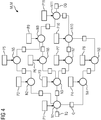
- An exemplary machine learning model MLM is illustrated in Fig. 4 .
- the parsing and the deployment system 1 is adapted to take a serialized representation of the machine learning model MLM which can be provided by a conventional model training tool and to transform it into a source code automatically. Accordingly, a user or developer does not need to produce a source code. Only a serialized machine learning model MLM has to be provided with possibly additional parameters such as names and sizes of input and/or output nodes of the machine learning model MLM.
- the machine learning model MLM can be represented by a computation graph such as illustrated in Fig. 4 .
- different nodes N represented by circles can perform operations on input data from queues Q represented by boxes and place the calculated result in output queues for the following nodes to continue processing. The operations themselves depend on a series of parameters P which are typically being automatically learned from received data.
- the machine learning model MLM provided by the training system 6 can be exported by the training system 6 as a serialized binary or text (XML, JSON) object containing the structure and operations of the computation graph as well as the learned parameters and may comprise optionally model metadata such as version numbers, units or signatures.
- the model parameters illustrated in the exemplary diagram of Fig. 4 can for instance comprise weight coefficients.
- the machine learning model MLM is parsed by the model parser 2 of the parsing and deployment system 1 to generate automatically a set of source code files SCF comprising at least one source code file and to extract parameters of the machine learning model MLM.
- the machine learning model MLM is a serialized model that comprises a text and/or binary string which encodes a description graph topology, nodes, operations and parameters, etc. that represent the machine learning model MLM.
- the extracted parameters of the machine learning model MLM are included into a source code of the at least one generated source code file SCF as constants and/or static variables.
- the extracted parameters of the machine learning model MLM are included into a separate parameter binary PB which is deployed along with a model binary MB into a memory of the target field device.
- the extracted parameters of the machine learning model MLM are included into a separate parameter file PF which is transformed into a corresponding parameter binary PB using the tool chain 3 specific to the target field device. The parameter binary PB is then combined with the model binary MB for deployment in a memory of the target field device.
- the model binary MB and/or parameter binary PB are deployed locally by copying them from the parsing and deployment system 1 into a memory of the target field device.
- the tool chain 3 comprises programs that receive a source code and generate automatically a software program.
- the last processing step of the tool chain 3 places the resulting binary into a memory 5 of the parsing and development system.
- the memory 5 is typically a disc of a machine where the tool chain 3 is implemented.
- the model binary MB and/or parameter binary PB can also be copied from the parsing and deployment system 1 via a network and a network interface of the target field device 10 into a local memory of the target field device 10. In general, it does not necessarily need to be transferred directly from the parsing and deployment system to the target field devices. It can be placed in some intermediate repository or system in charge of performing updates on the field device.
- the model binary MB and parameter binary PB can be stored in a possible embodiment in a non-volatile memory 12 of the target field device 10 and then loaded into a main memory 13 of the target field device 10 for execution by at least one processing unit 14 of the target field device 10.
- Fig. 1 illustrates a possible exemplary embodiment of a target field device 10 according to an aspect of the present invention.
- the target field device 10 comprises an interface 11, a processing unit 14 such as a CPU.
- the target field device 10 can comprise input and/or output interfaces 15.
- the non-volatile memory 12 can be connected to the central processing unit 14 via a memory controller.
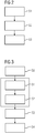
- Fig. 2 shows a possible exemplary embodiment of a method for deployment of a machine learning model MLM on a target field device 10 according to the first aspect of the present invention.
- a set of source code files SCF is generated automatically on the basis of the machine learning model MLM provided by the training system 6.
- the set of source code files SCF is adapted to execute the machine learning model MLM according to predetermined capabilities of the target field device 10.
- the generated source code files SCF are transformed into a model binary MB using the tool chain 3 specific to the target field device 10.
- the model binary MB is deployed in step S3 in a memory 12 of the target field device 10.
- This memory 12 is in a preferred embodiment a non-volatile memory.
- step S1 an automatic transformation of the machine learning model MLM into a source code is performed.
- the model parser 2 of the parsing and deployment system 1 goes through the serialized model object and replicates the computation graph topology into a syntax suitable to be compiled in a low-level language for the target field device 10, e.g. C/C++.
- the resulting source code files SCF effectively implement a standalone module where instructions and operations are instantiated in a sequence such that they result in the same computation graph as the exported machine learning model MLM.
- the generated program is optimized to execute the individual machine learning model MLM from which it is generated.
- the method as illustrated in the flowchart of Fig. 2 can be performed in the development environment of the target field device 10. It is different from the execution environment of the device 10 itself and can also be different to the environment used to train the machine learning model MLM.
- the model parser 2 of the system 1 as illustrated in Fig. 1 can make use of information about a set of libraries and modules available for the respective target field device 10, e.g. operations performed and interfaces.
- the model parser 2 has knowledge about device-specific modules for operations such as matrix multiplications, convolutions, non-linear functions, etc. which are typical building blocks of machine learning models MLM.
- These libraries can be preimplemented once in an optimized way for the deployment system 1 according to the above-mentioned qualities and requirements, and can be re-used for every new machine learning model MLM that has to be deployed.
- a computer program is automatically built, i.e. compiled and linked, from the auto-generated source code files SCF and the device-specific libraries and modules, using the tool chain 3 suitable for the target device 10.
- the result is a standalone binary program MB which can be executed on the field device 10.
- the generated model binary MB is deployed in step S3 in the memory of the target field device 10.
- the machine learning module is integrated into the firmware of the target device 10.
- the auto-generated source code is not given directly to a toolchain. Instead, the generated code is integrated with other source code implementing other functions of the field device 10. This integration can take place for example in a configuration management tool.
- all the source code auto-generated ML code and unrelated, general device source code
- Model parameters of the machine learning model MLM can be parsed in different ways.
- One alternative is to include them directly in this generated source code of the source code file SCF. For example, they are added to the source code files as initialized static variables and constants. In this way, they form part of the resulting model binary MB after the building step.
- the extracted parameters can be placed during the parsing in separate objects such as binary files.
- the machine learning model MLM is transformed automatically into a suitable form for deployment on resource-constrained target field devices 10 running real-time applications.
- the target field device 10 as illustrated in Fig. 1 receiving a model to be deployed from the parsing and deployment system 1 can be for instance a programmable logical controller PLC or an electrical grid digital protection relay.
- the generated model binary MB deployed in the memory of the target field device 10 has the advantage that it uses only the required system resources of the target field device 10 to implement the machine learning model MLM of interest. Further, the deployed model binary MB complies with run-time policies imposed by the target system or target device 10. For example, no additional memory requests to the operating system after program start are necessary and there is no exception throwing. Further, no extensive manual code development is required.
- Fig. 3 shows a block diagram of a further possible embodiment for deployment and execution of a machine learning model MLM on a target field device 10.
- a training step S0 is performed previous to the generation of the source code files SCF in step S1.
- the model binary MB is loaded in step S4 into a main memory 3 of the target field device 10 for execution.
- the deployment can take place locally by copying a file from a storage medium physically attached to the device or remotely e.g. via a network interface.
- the model can be deployed in various forms, such as integrated with a full firmware update, as a standalone library or as an executable binary. In the latter case, the functionality implemented by the model can be offered to customers as a standalone application which can be updated as improved models become available.
- the deployment can take place to a non-volatile memory of the target field device 10 or a similar permanent storage facility such as a disk drive. After this point, execution of the model in a standalone mode (without the need for a generic model interpreter capable of scoring/executing multiple different models) can take place.
- the model binary MB is initially placed into the main memory 13 by a loader. If the model parameters are contained within the model binary MB, no further transfer of information to the main memory 13 is required from the non-volatile memory 12 of the target field device 10.
- the machine learning model MLM can be executed on the target field device 10 by a processing unit with a lower and predictable amount of required system resources.
- Model training and testing can take place with standard tools independent of the restrictions and required software imposed by the target device 10. Further, the resulting program is guaranteed to run on the target device 10, i.e. it is possible to guarantee that all its dependencies are satisfied and that it complies with the requirements of the target device 10. Moreover, the resulting program is sufficient in the use of system resources and can be deployed in a standalone manner. It can contain exclusively the instructions and data required for evaluation of a single model. Hence, it does not require a generic model interpreter running on the target device 10. Further, the resulting program can be made suitable for real-time applications because it uses a fixed amount of resources and has a predictable execution time. An update of the machine learning models can be streamlined requiring in most cases no manual code development for a development and update of new machine learning models MLM.
- the invention provides according to a further aspect a method for executing a machine learning model MLM on a field device such as a field device 10 as illustrated in Fig. 1 . Further exemplary embodiments of the field device 10 are shown in Figs. 5, 6 .
- the method for executing a machine learning model MLM on a field device 10 comprises executing basic operations of the machine learning model MLM divided into operation groups of basic operations according to a schedule. The basic operations of an operation group are executed while model parameters of a subsequent operation group are loaded.
- the basic operations are executed depending on a precalculated set of execution configurations.
- the basic operations of an operation group can be executed by at least one processing unit such as the processing unit 14 illustrated in Fig. 1 of the field device 10 while model parameters of a subsequent operation group are loaded simultaneously from a non-volatile memory unit of the field device 10, such as the non-volatile memory 12, into a main memory of the field device 10, such as the main memory 13 illustrated in Fig. 1 .
- the precalculated set of execution configurations can comprise one or more of the following: a placement of operation nodes of the machine learning model MLM into operation groups of basic operations, a sequence of execution of operation nodes and/or operation groups, a selection of an amount of input and/or output batching to be performed between operation nodes of the machine learning model MLM and/or a location on a non-volatile memory 12 of the field device 10 for model parameters corresponding to operation nodes of each operation group.
- the set of execution configurations is precalculated on the basis of a graph topology of the machine learning model MLM including dependencies between operation nodes N of the machine learning model MLM, an available program memory of the field device 10 and/or an admissible execution latency and/or a load time for loading model parameters P from a memory unit of the field device 10 into a processing unit 14 of the field device 10 and/or an execution time of basic operations for each operation node of the machine learning model MLM of the field device 10.
- the model parameters P of a subsequent operation group are loaded into the main memory 13 of the field device 10 in response to load requests issued by a machine learning program implementing the machine learning model MLM and executed by a processing unit 14 of the field device 10.
- a load request is issued by the machine learning program running on the CPU 14 of the target field device 10.
- There can be a module in charge of implementing the schedule i.e. coordinate the execution of operation groups and the loading of operation parameters P according to the schedule.
- the target field device 10 comprises a single processing unit 14.
- the target field device 10 can also comprise multiple processing units, for example a multicore system or a system with additional processing units such as Graphics Processing Units (GPU) or Field Programmable Gate Arrays (FPGA).
- graphics processing Units GPU
- FPGA Field Programmable Gate Arrays
- the used machine learning model MLM can comprise different kinds of machine learning models MLM, in particular an artificial neural network, a convolutional neural network CNN, a recurrent neural network RNN, multilayer perceptrons, a decision tree model and/or a random forest model.
- the machine learning model MLM can itself be a combination, i.e. ensemble of multiple different models.
- the machine learning model MLM is typically represented by a computation graph as illustrated in Fig. 4 .
- the nodes N of the machine learning model MLM represented by circles are adapted to perform operations of input data received from input queues Q and place the results of the operation in output queues for the next layer of nodes to continue processing. Operations performed by the nodes N can be depend on a series of parameters, for instance weighting coefficients. The parameters can typically be learned automatically from data.
- the parameters P associated to the operation nodes N require memory resources on the target field device 10 which executes the model. The same applies to the queues Q between the operation nodes N which can be designed to provide capacity for multiple input output values. Additionally, the instructions to be performed by the operation nodes N as well as their internal variables also require system memory.
- the field device 10 which is used to run the model can comprise a main memory 13 and a non-volatile memory 12 as depicted in the embodiments of Figs. 5, 6 .
- the main memory 13 is typically fast but also costly and provides limited memory space.
- the main memory 13 can be based on technologies such as SRAM or DRAM including non-volatile or battery-packed versions.
- the main memory 13 can communicate with the processing unit 14 of the target field device 10 which executes programs, for example via a system bus 16 as illustrated in Figs. 5, 6 .
- the non-volatile memory 12 can be internal to the target device 10 as illustrated in Fig. 5 or can be external as illustrated in the embodiment of Fig. 6 .
- the non-volatile memory 12 can be implemented by a memory card such as SD cards or CFAST cards.
- the target device 10 can also comprise both types of memory cards.
- the non-volatile memory 12 is typically less costly than the main memory 13. It can be based on different technologies, for instance NAND or NOR flash memory. In general, it presents certain disadvantages compared to the main memory 13 including slow read times, slow write times and a limited lifespan due to erase and write cycles.
- the non-volatile memory 12 can be connected to the processing unit 14 of the target field device 10 via a memory controller 17 as shown in Figs. 5, 6 .
- the memory controller 17 receives requests or commands from the processing unit 14, for example via the same system bus 16.
- the memory controller 17 can be requested to provided certain pages or blocks from the non-volatile memory 12 to the processing unit 14 or to copy them directly to a certain area of the main memory 13 without CPU involvement, e.g. by using a DMA mechanism.
- the memory controller 17 is adapted to interpret requests and manages the memory accordingly in order to perform the requests. This communication can take place using several serial or parallel interfaces specific to the memory type such as SPI or SD interfaces.
- NAND flash memory typically used in memory cards
- operations must be performed in pages or blocks of certain size, wherein the size in turn depends on the nature of the operations themselves (read, write, erase).
- Placement of model parameters in the memory and access during model execution can affect performance. For instance, random access across many different pages would be substantially slower than sequential access of parameters tightly packaged in fewer pages.
- the field device 10 comprises a memory controller 17 adapted to load model parameters of a subsequent operation group from the memory unit 12 of the field device 10 into the main memory 13 of the field device 10 in response to received load requests issued by a machine learning program implementing the machine learning model MLM and executed by the processing unit 14 of the field device 10.
- the memory unit storing model parameters P of the machine learning model MLM is in a preferred embodiment a non-volatile memory 12.
- the main memory 13 for which the program running on the processing unit 14 reads data forms part of the target field device 10.
- the main memory 13 can be formed by a random access memory RAM, for example SRAM or DRAM.
- the main memory 13 can also be formed by a non-volatile RAM (nvRAM) or by a flash memory e.g. NOR flash memory.
- nvRAM non-volatile RAM
- NOR flash memory flash memory e.g. NOR flash memory.
- the non-volatile memory 12 can be typically a NAND flash memory. It can be also formed by other types of flash memories, e.g. NOR flash memory.
- the non-volatile memory 12 can be located in the target field device 10 as illustrated in Fig. 5 or located externally and connected to the target field device 10 as illustrated in Fig. 6 . It can be formed by memory card such as an SD card, MMC card, CFAST card or a USB drive or it can be formed by a hard drive.
- memory card such as an SD card, MMC card, CFAST card or a USB drive or it can be formed by a hard drive.
- a set of execution configurations EC is calculated prior to deployment.
- This set of execution configuration can comprise a placement of operation nodes of the machine learning model MLM into operation groups of basic operations, a schedule or a sequence of execution of the operation nodes and/or operation groups, a selection of the amount of input and/or output batching to be performed between operation nodes and/or a location on the device's non-volatile memory for the parameters corresponding to operation nodes on each operation group.
- the calculation of execution configuration can be performed taking into account the topology of the graph (dependencies between operation nodes), a limit of total program memory available and the execution latency.
- the calculation can further take into account a load time from the non-volatile memory 12 (for different block sizes) on the target field device 10 and/or the execution time for each operation node on the target field device 10.
- the calculation can be designed to provide execution configurations that guarantee the following: the amount of memory required at any given times does not exceed the memory limit set. In practice, this requires that the amount of memory required for the parameters of any two consecutive groups does not exceed a certain allocated amount of parameter memory. Further, the execution configurations guarantee that the latency requirements are met.
- the execution configurations are selected that maximize performance. Accordingly, the amount of CPU idle time (or wait time while parameters are loaded from the non-volatile memory 12) is minimized.
- the parameter placement in memory and schedule are consistent to increase performance (e.g. ensure sequential access to blocks if this improves the read throughput).
- the program is deployed on the target field device 10 typically in a preferred embodiment to a non-volatile memory 12. It is deployed together with the model parameters, placed on specific locations. Additionally, the program contains information about other execution configurations such as schedule and/or batching. The deployment can be done via a network interface or an external memory card can be connected to the device for copying the program and parameters.
- the program is loaded into the main memory 13 and performs a series of operations as required by the operation nodes according to the schedule provided and issues a series of requests to load coefficients from the non-volatile memory 12, also according to the schedule.
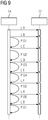
- These requests can be handled by the non-volatile memory controller in parallel to the program execution by the processing unit 14. That is, while the processing unit 14 is performing operations using a given set of parameters, a transfer of the next set of parameters from the non-volatile memory 12 to the main memory 13 can be performed in parallel.
- FIG. 7 illustrates an initialization sequence while Fig. 8 illustrates the model execution on the CPU 14 of the target field device 10.
- the initialization sequence comprises four steps S71, S72, S73, S74.
- an indicator n is initialized to be 0.
- n is indicating the current operation group in the schedule.
- a request to load parameters of operation group 0 is issued.
- the initialization sequence ends in step S74.
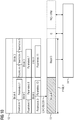
- the model execution can be performed by the processing unit 14 of the target field device 10 as illustrated in the flow diagram of Fig. 8 .
- the model execution starts in step S81.
- step S82 it is checked whether input data is available to the machine learning model MLM or not. If there is no input data the model execution stops in step S83. If input data is available the input data is fetched in step S84. In step S85, it is checked whether the parameters P of the operation group n have been loaded. If not, the process waits in step S86 for the parameters P to be loaded and optionally other tasks are processed by the CPU 14. If in step S86 the parameters P of group n have been loaded, in step S87 it is requested to load parameters P of the next operation group (n+1) according to the schedule. Then, in step S88, a node group n is processed.
- step S810 it is checked whether n is 0 or not. If n is not 0, the process returns to step S85. If n becomes 0, the process returns to step S82 as illustrated in Fig. 8 .
- the flow diagram of Fig. 8 describes the behaviour of the program on each cycle (for example on each PLC scan cycle). The flow comprises two loops, i.e. an outer loop through the available inputs of the machine learning model MLM and an inner loop through all node groups, performing loading and execution steps in parallel.
- the exemplary simplified machine learning model MLM as illustrated in Fig. 4 has specific memory requirements or model parameters and requirements for an execution time on a particular target device 10 as given in Table 1.
- Node Param. Exec. Time 1 10 kB 12 us 2 20 kB 13 us 3 10 kB 5 us 4 10 kB 10 us 5 10 kB 8 us 6 10 kB 10 us 7 25 kB 25 us 8 22 kB 14 us 9 15 kB 10 us 10 15 kB 15 us 11 28 kB 24 us Total 175 kB 146 us
- the best scenario for execution time of the model for a given input is 146 ⁇ s. That would be the case if all parameters of the model are in memory occupying a memory space of 175 kB and no loading of parameters P is required. It is, however, possible to optimize the execution so that much less memory is utilized, with a minimal penalty on the execution time.
- the target device 10 comprises an NAND flash non-volatile memory 12 where the page size is 16 kB and a page can be loaded to the main memory 13 of the target device 10 within 50 ⁇ s. It is possible to place the operation nodes of the model into groups, for example as indicated in Table 2. Group Nodes Mem. Position Schedule Batch Group 1 1, 2 Block A Step 1 4 Group 2 3, 4, 5 Block B Step 2 4 Group 3 6, 8 Block C Step 3 4 Group 4 7 Block D Step 4 4 Group 5 9, 10 Block E Step 5 4 Group 6 11 Block F Step 6 4
- the grouping is such that the parameters in an operation group fit in two pages (32 kB). Loading from the non-volatile memory 12 the parameters for an operation group takes approximately 100 ⁇ s, and processing the group takes 25 ⁇ s in a worst case. For these values, an execution strategy would be to use just 64 kB of the main memory 13 (the equivalent of four pages) where at any given time two of them are being used by the running program processing a given group of nodes, and another two are being loaded with the parameters for the next or subsequent operation group.
- the wait time while operation parameters are being loaded is minimized.
- the minimum can be achieved when the execution time of the current group is the same as the loading time of the next group.
- This can be tuned, for example, via batching of many inputs. Assuming that the overhead for storing an additional set of intermediate elements is small compared to the amount of parameters of the operation nodes and that a latency of up to 1 ms is acceptable for a model input to be processed it is possible to batch four inputs together to have a worst case execution time for a group of 100 ⁇ s, comparable with the time to load parameters of each group.
- Fig. 10 shows the state of memory in the given example during execution of nodes in group 4, while loading of parameters of nodes in group 5.
- the system processes four different inputs applied to the model in approximately 600 ⁇ s, that is, on average 150 ⁇ s, adding a very small overhead compared to the best case where all parameters are in the memory at once (146 ⁇ s).
- the scheduling does not exceed the latency requirement and uses a reduced amount of memory, e.g. 64 kB for parameters and a small overhead for queues.
- Fig. 9 illustrates the interaction between the processing unit 14 and the memory controller 17 of a target device 10.
- the load requests are issued by a machine learning program running on the processing unit 14.
- a component of the program can be in charge of implementing the schedule, i.e. coordinate the execution of operation groups and the loading of operation parameters according to the schedule.
- the basic operations of an operation group are executed by performing processing of data with the loaded parameters by the CPU 14 while in parallel normal parameters of a subsequent operation group are loaded by the memory controller 17.
- the non-volatile memory 12 of the target device 10 stores the parameters P of the machine learning model MLM illustrated in Fig. 4 .
- the machine learning model MLM of Fig. 4 comprises eleven operation nodes N with associated operation parameters P.
- the parameters P such as weighting coefficients or the different operation nodes N of the machine learning model MLM are stored in memory blocks A to F of the non-volatile memory 12 as illustrated in Fig. 10 .
- the grouping is such that the parameters P in a group fit in two pages (32 kB). For instance, the operation nodes 1, 2 of the machine learning model MLM of Fig. 4 require 10 kB plus 20 kB, i.e.
- the main memory 13 comprises a parameter memory space for two blocks, block E and block D in the give example. Further, the main memory 13 has additional memory space for the queues Q of the machine learning model MLM and can comprise a fixed program memory including instructions and data.
- the central processing unit CPU 14 of the target device 10 has direct access to the main memory 13 as illustrated in Fig. 10 .
- the parameters of block E i.e. group 5 comprising nodes 9, 10 are loaded while parameters P of block D are processed by the processing unit 14. Accordingly, the basic operations of the operation group related to operation node 7 of the machine learning model (loaded from block D of non-volatile memory 12) are executed while at the same time parameters P of a subsequent operation group 5 comprising operation nodes 9, 10 of the machine learning model MLM are loaded from block E of the non-volatile memory 12.
- the method according to the present invention is adapted to process, store and evaluate machine learning models MLM on target field devices 10 in such a way that the amount of main memory 13 required is reduced. This makes it possible to evaluate large machine learning models MLM or making execution of small machine learning models MLM more efficient. Further, the method for executing a machine learning model on a field device 10 according to the third aspect of the present invention does minimize the idle time waiting for parameters P to be loaded, that is it reduces the overhead added when compared to an ideal scenario (having always all parameters stored in the main memory 13).
- the operations in a machine learning model MLM can be grouped and the corresponding parameters P of each group can be stored in the non-volatile memory 12 in specific locations.
- a predetermined schedule is followed such that the execution of a group of operations and the loading of the parameters P of the next group into the main memory 13 can be performed in parallel.
- the method enables the deployment and execution of arbitrarily large machine learning models MLMs and/or artificial intelligence algorithms and models into industrial field devices such as PLCs which comprise a restricted amount of memory resources.
Description
- The invention relates to a method for deployment and execution of a machine learning model on a field device, in particular on a memory restricted industrial field device such as a programmable logic controller PLC. Electronic industrial field devices, e.g. digital protection relays or programmable logic controllers PLC are built for reliability and typically make use of high-end, components, in particular high end memory components like non-volatile RAM or other types of battery-backed RAM or dedicated retentive memories able to prevent data loss for example in case of power failures. Programs running on such industrial field devices tend not to require large amounts of main memory, but must offer real-time guarantees. Therefore, field Devices hosting these programs must often operate in real-time, i.e. they must perform actions within strict time budgets. For instance, an electronic field device may trigger a protection mechanism within an electrical power supply grid or may control certain manufacturing steps in a manufacturing process within a predetermined time. Accordingly, there are strict deadlines to complete execution of the program running on a processing unit of the field device. Field devices also take part in safety critical applications and must therefore operate in real-time with strict time budgets.
- Field devices comprise only limited available physical resources for deployment and execution of programs. The memory space of the main memory available in these field devices is typically very small (e.g. 1 to 20 MB) compared to devices used in non-industrial non-real-time computing environments. Further, the program and software run on such field devices have to meet strict quality requirements. In order to meet these requirements programs run on field devices are normally developed in low-level programming languages such as C/C++ and are then manually optimized and verified by trained software and firmware developers.
- On the other hand, machine learning, ML, presents a different paradigm whereby computers are able to learn and develop programs without being explicitly programmed. In this context, developers equipped with various software tools are able to automatically produce machine learning models from sets of training data. For example, a developer may want to provide a machine learning model to estimate the distance of a failure on an electrical power supply grid based on a raw electrical current and voltage data from previous power supply failures. The developer may in this case design a machine learning model. This machine learning model can comprise typically a computation graph defining a sequence of operations to be performed on the received raw data, for example coming from sensors or measurement devices on field devices. The machine learning model can contain a certain number of parameters that have to be learned from the received data. Once the machine learning model has been trained with training data, it can be brought into operation. This means, the same sequence of operations together with automatically learned parameters can be applied to the received new raw data in order to classify them. For instance, the raw data can comprise data coming from subsequent electrical faults in a power supply grid and the machine learning model can be used to estimate the location of the faults within the electrical power supply grid.
- After machine learning models are developed, they are brought into operation. This is conventionally achieved by first generating a full description of the algorithm (including all operations and parameters) in a serialized format (for example using XML or json format, or a similar binary or text-based representation), and deploying said serialized model to the device of interest (e.g. a field device). In the field device, an interpreter program is able to interpret the serialize representation, and perform the operations described on local data. This is inefficient and unsuitable for embedded systems and industrial field devices for different reasons. A disadvantage of this conventional approach is the need for a model interpreter module itself. These modules typically use system resources in amounts which are unsuitable for field-devices as described above. This inefficiency in resource utilization is related to the fact that interpreters are able to parse a potentially wide range of machine learning models. In practice, however, machine learning models running on field devices at any given time only require a subset of the functionality provided by a model interpreter, therefore leading to an inefficient use of system resources. Further, model interpreters used in the conventional approach are developed in many cases in high-level programming languages, like Python, or language producing programs running on a virtual machine or interpreter, like Java. This facilitates the development of flexible interpreters able to understand a wide variable of machine learning models, but presents many disadvantages such as non-efficient use of resources or non-deterministic execution time which can be required for real-time systems. They may make use of services from an operating system which are not available on some embedded devices like PLC controllers, such as requests for additional memory during run-time (dynamic memory allocation) or handling of exception. Further, the non-deterministic resource utilization makes the programming languages used in the conventional approach unsuitable for real-time applications.
- A further conventional approach involves the manual coding and optimization of a machine learning program implementing a trained model. However, this is very cumbersome and causes high efforts in development and testing of the system, especially when the machine learning model has to be updated frequently.
- A further alternative approach involves the extraction of raw data from the field device to which the machine learning mod-el has to be applied and to send the extracted raw data to another device where a model interpreter module can be executed without restrictions. The device with the model interpreter module can be connected via many different kinds of interfaces to the field device operating in real-time. The main disadvantage of this conventional approach is that it provides an additional latency incurred to extract the data from a field device, and to feed the results produced by the machine learning model back to the field device.
-
US 2011/0078652 A1 discloses graphical partitioning of executable graphical models, such as block-diagram models, for execution on concurrent computing resources. - Jeff Barnes discloses in "Azure Machine Learning Microsoft Azure Essentials", XP055374060, ISBN: 978-0-7356-9817-8, general Machine Learning (ML) algorithms and implementations.
- Accordingly, it is an object of the present invention to provide a method and apparatus to deploy and execute a machine learning model on a field device efficiently.
- This object is achieved according to a first aspect by a method for deployment of a machine learning model on a target field device comprising the steps of:
- generating automatically a set of source code files on the basis of the machine learning model, wherein the set of source code files is adapted to execute the machine learning model according to predetermined capabilities of the target field device,
- transforming the generated source code files into a model binary using a tool chain specific to the target field device; and
- deploying the model binary in a memory of the target field device.
- In a possible embodiment of the method for deployment of a machine learning model on a target field device according to the first aspect of the present invention, the machine learning model is parsed by a model parser to generate automatically at least one source code file and to extract parameters of the machine learning model.
- In a further possible embodiment of the method for deployment of a machine learning model on a target field device according to the first aspect of the present invention, the machine learning model is represented by a serialized model comprising a text or binary string which encodes a graph topology including nodes, operation of nodes, interconnection of nodes and parameter of nodes.
- In a still further possible embodiment of the method for deployment of a machine learning model on a target field device according to the first aspect of the present invention, the extracted parameters of the machine learning model are included into a source code of at least one generated source code file as constants and/or static variables.
- In a still further possible embodiment of the method for deployment of a machine learning model on a target field device according to the first aspect of the present invention, the extracted parameters of the machine learning model are included into a separate parameter binary which is deployed along with the model binary in a memory of the target field device.
- In a still further possible embodiment of the method for deployment of a machine learning model on a target field device according to the first aspect of the present invention, the extracted parameters of the machine learning model are included into a separate parameter file which is transformed into a parameter binary using the tool chain specific to the target field device, wherein the parameter binary is combined with the model binary for deployment in a memory of the target field device.
- In a further possible embodiment of the method for deployment of a machine learning model on a target field device according to the first aspect of the present invention, the model binary and/or parameter binary are deployed locally by copying them from the tool chain into a memory of the target field device or remotely by copying them via a network and a network interface of the target field device into a memory of the target field device.
- In a still further possible embodiment of the method for deployment of a machine learning model on a target field device according to the first aspect of the present invention, the machine learning model used for generating the source code files comprises a machine learning model trained with training data and/or tested with test data.
- In a still further possible embodiment of the method for deployment of a machine learning model on a target field device according to the first aspect of the present invention, the machine learning model is parsed by a model parser having access to a database comprising a set of libraries and device compatible operation modules of the target field device.
- In a still further possible embodiment of the method for deployment of a machine learning model on a target field device according to the first aspect of the present invention, the model binary and parameter binary are stored in a non-volatile memory of the target field device and loaded into a main memory of the target field device for execution by at least one processing unit of the target field device.
- The invention further provides according to a second aspect a deployment system for deployment of a machine learning model on a target field device, wherein said deployment system comprises
a model parser configured to parse the machine learning model to generate at least one source code file adapted to execute the machine learning model using available resources of the target field device and
a tool chain specific to the target field device adapted to transform the at least one source code file into a model binary for deployment in a memory of the target field device. - In a possible embodiment of the deployment system for deployment of a machine learning model on a target field device according to the second aspect of the present invention, the model parser has access to a database comprising a set of libraries and device-compatible operation modules of the target field device.
- In a further possible embodiment of the deployment system for deployment of a machine learning model on a target field device according to the second aspect of the present invention, the model parser is configured to extract parameters of the machine learning model and to include them into a source code of at least one generated source code file as constants and/or static variables.
- In a further possible embodiment of the deployment system for deployment of a machine learning model on a target field device according to the second aspect of the present invention, the model parser is configured to extract parameters of the machine learning model and to include them into a separate parameter binary which is deployed along with the model binary in a memory of the target field device.
- In a still further possible embodiment of the deployment system for deployment of a machine learning model on a target field device according to the second aspect of the present invention, the model parser is configured to extract parameters of the machine learning model and to include them into a separate parameter file which is transformed into a parameter binary using the tool chain specific to the target field device, wherein the parameter binary is deployed along with the model binary in a memory of the target field device.
- The invention further provides according to a third aspect a method for executing a machine learning model on a field device comprising executing basic operations of the machine learning model divided into operation groups of basic operations according to a schedule,
wherein basic operations of an operation group are executed while model parameters of a subsequent operation group are loaded. - In a possible embodiment of the method for executing a machine learning model on a field device according to the third aspect of the present invention, the basic operations are executed depending on a precalculated set of execution configurations.
- In a further possible embodiment of the method for executing a machine learning model on a field device according to the third aspect of the present invention, basic operations of an operation group are executed by at least one processing unit of the field device while model parameters of a subsequent operation group are loaded simultaneously from a non-volatile memory unit of the field device into a main memory of the field device.
- In a further possible embodiment of the method for executing a machine learning model on a field device according to the third aspect of the present invention, the execution configuration comprises one or more of the following:
- a placement of operation nodes of the machine learning model into operation groups of basic operations,
- a sequence of execution of operation nodes and/or operation groups,
- a selection of an amount of input and/or output batching to be performed between operation nodes of the machine learning model,
- a location on a non-volatile memory of the field device for model parameters corresponding to operation nodes on each operation group.
- In a still further possible embodiment of the method for executing a machine learning model on a field device according to the third aspect of the present invention, the set of execution configurations are precalculated on the basis of a graph topology of the machine learning model including dependencies between operation nodes of the machine learning, ML, model, an available program memory of the field device, and/or an admissible execution latency, and/or a load time for loading model parameters from a memory unit of the field device into a processing unit of the field device and/or on the basis of an execution time of basic operations for each operation node of the machine learning model on the field device.
- In the method of the invention for executing a machine learning model on a field device according to the third aspect of the present invention, the model parameters of a subsequent operation group are loaded into a main memory of the field device in response to load requests issued by a machine learning program implementing the machine learning model executed by a processing unit of the field device.
In a still further possible embodiment of the method for executing a machine learning model on a field device according to the third aspect of the present invention, the method is performed by at least one processing unit of the field device in real time.
In a still further possible embodiment of the method for executing a machine learning model on a field device according to the third aspect of the present invention, the machine learning model comprises
an artificial neural network,
a convolutional neural network,
a recurrent neural network,
multilayer perceptrons
a decision tree mode and/or
a random forest model.
The invention further provides according to a fourth aspect a field device comprising
a memory unit storing model parameters of a machine learning model and
a processing unit adapted to execute basic operations of the machine learning model divided into operation groups of basic operations according to a schedule,
wherein basic operations of an operation group are executed by the processing unit while model parameters of a subsequent operation group are loaded from the memory unit of the field device. - In a possible embodiment of the field device according to the fourth aspect of the present invention, the processing unit is programmed to execute the basic operations depending on a precalculated set of execution configurations.
- In a still further possible embodiment of the field device according to the fourth aspect of the present invention, the set of execution configuration comprises at least one of the following:
- a placement of operation nodes of the machine learning model into operation groups of basic operations,
- a sequence of execution of operation nodes and/or operation groups,
- a selection of an amount of input and/or output batching to be performed between operation nodes of the machine learning model,
- a location on a non-volatile memory unit of the field device for model parameters corresponding to operation nodes of each operation group.
- In a further possible embodiment of the field device according to the fourth aspect of the present invention, the field device comprises a memory controller programmed to load model parameters of a subsequent operation group from the memory unit of the field device into a main memory of the field device in response to received load requests issued by a machine learning program implementing the machine learning model and executed by a processing unit of the field device. In a possible embodiment of the field device according to the fourth aspect of the present invention, the memory unit storing model parameters of the machine learning model is a non-volatile memory.
- In a further possible embodiment of the field device according to the fourth aspect of the present invention, the field device comprises a programmable logical controller.
- In a still further possible embodiment of the field device according to the fourth aspect of the present invention, the field device comprises a digital protection relay.
- The invention further provides a program comprising instructions for performing a method for executing a machine learning model on a field device according to the third aspect of the present invention.
- In the following, possible embodiments of the different aspects of the present invention are described in more detail with reference to the enclosed figures.
- Fig. 1
- shows a possible exemplary embodiment of a system for deployment and executing a machine learning model on a target field device according to an aspect of the present invention;
- Fig. 2
- shows a flowchart of a possible exemplary embodiment of a method for deployment of a machine learning model on a target field device according to an aspect of the present invention;
- Fig. 3
- shows a further flowchart for illustrating a further possible exemplary embodiment of a method for deployment and execution of a machine learning model on a target field device according to an aspect of the present invention;
- Fig. 4
- shows a schematic graph for illustrating a possible exemplary embodiment of a machine learning model used in the context of the present invention;
- Figs. 5, 6
- illustrate block diagrams for illustrating possible exemplary embodiments of field devices according to an aspect of the present invention;
- Fig. 7
- shows a flowchart for illustrating a program initialization in a field device according to the present invention;
- Fig. 8
- shows a flow diagram for illustrating a program execution within a field device according to the present invention;
- Fig. 9
- shows a sequence diagram for illustrating the execution of machine learning model according to an aspect of the present invention;
- Fig. 10
- shows a diagram for illustrating a program memory use and data transfer as employed by a field device according to an aspect of the present invention.
-
Fig. 1 shows a schematic block diagram for illustrating a possible exemplary embodiment of a system for deployment and execution of a machine learning model MLM on a target field device. Thedeployment system 1 illustrated inFig. 1 comprises amodel parser 2 and atool chain 3 specific to a target field device. Themodel parser 2 is configured to parse a machine learning model MLM to generate automatically at least one source code file SCF. As illustrated inFig. 1 , themodel parser 2 is configured to parse a trained machine learning model to generate automatically a set of source code files SCF. The source code file SCF is adapted to execute the machine learning model MLM using available resources of atarget field device 10. Thetool chain 3 of thesystem 1 is specific for the target field device and is adapted to transform the at least one source code file SCF into a model binary MB for deployment in a memory of the target field device. Thetool chain 3 can comprise in a possible embodiment a compiler, a linker, a debugger and an archiver. As illustrated inFig. 1 , themodel parser 2 has access to adatabase 4. Thedatabase 4 can comprise in a possible implementation a set of libraries and device-compatible operation modules of the respective target field device. The operation modules are compatible to thetarget field device 10 but can still be generic in the sense that they are suitable for different field devices. - In a possible first variant of the parsing and
deployment system 1 illustrated inFig. 1 , themodel parser 2 is configured to extract parameters P of the machine learning model MLM and to include the extracted parameters into the source code of at least one generated source code file SCF as constants or static variables. In an alternative embodiment, themodel parser 2 is configured to extract parameters of the machine learning model MLM and to include them into a separate parameter binary PB which is deployed along with the model binary MB in a memory of thetarget field device 10. The variant reduces the amount of required memory but has a performance penalty. - In a still further third variant of the
deployment system 1, themodel parser 2 is configured to extract parameters of the machine learning model MLM and to include them into a separate parameter file PF which is transformed into the parameter binary PB using thetool chain 3 specific to the target field device. The parameter binary PB is then deployed along with the model binary MB in the memory of thetarget field device 10. The model binary MB and the parameter binary PB can be stored temporarily in amemory 5 of the parsing anddeployment system 1 as illustrated inFig. 1 . - The machine learning model MLM is a trained machine learning model MLM trained within a
training system 6. Thetraining system 6 comprises a machine learningmodel training module 7 receiving training and/or testing data from adata source 8. The machine learning model MLM is trained by themodule 7 with the received training data and then tested with test data. The trained machine learning model MLM can be stored temporarily in amemory 9 of thetraining system 6 as illustrated inFig. 1 . The training of the machine learning model MLM can be performed independently from the target field device. The machine learning model MLM can be trained in a model training environment and can then be applied to the parsing anddeployment system 1 as shown inFig. 1 . The machine learning model MLM is represented by a serialized model comprising a text or binary string which encodes a graph topology including nodes, operation of nodes, interconnection of nodes and/or parameter of nodes. An exemplary machine learning model MLM is illustrated inFig. 4 . The parsing and thedeployment system 1 is adapted to take a serialized representation of the machine learning model MLM which can be provided by a conventional model training tool and to transform it into a source code automatically. Accordingly, a user or developer does not need to produce a source code. Only a serialized machine learning model MLM has to be provided with possibly additional parameters such as names and sizes of input and/or output nodes of the machine learning model MLM. The machine learning model MLM can be represented by a computation graph such as illustrated inFig. 4 . In the illustrated diagram, different nodes N represented by circles can perform operations on input data from queues Q represented by boxes and place the calculated result in output queues for the following nodes to continue processing. The operations themselves depend on a series of parameters P which are typically being automatically learned from received data. The machine learning model MLM provided by thetraining system 6 can be exported by thetraining system 6 as a serialized binary or text (XML, JSON) object containing the structure and operations of the computation graph as well as the learned parameters and may comprise optionally model metadata such as version numbers, units or signatures. The model parameters illustrated in the exemplary diagram ofFig. 4 can for instance comprise weight coefficients. - The machine learning model MLM is parsed by the
model parser 2 of the parsing anddeployment system 1 to generate automatically a set of source code files SCF comprising at least one source code file and to extract parameters of the machine learning model MLM. The machine learning model MLM is a serialized model that comprises a text and/or binary string which encodes a description graph topology, nodes, operations and parameters, etc. that represent the machine learning model MLM. - In a possible embodiment, the extracted parameters of the machine learning model MLM are included into a source code of the at least one generated source code file SCF as constants and/or static variables. Alternatively, the extracted parameters of the machine learning model MLM are included into a separate parameter binary PB which is deployed along with a model binary MB into a memory of the target field device. In a further possible alternative embodiment, the extracted parameters of the machine learning model MLM are included into a separate parameter file PF which is transformed into a corresponding parameter binary PB using the
tool chain 3 specific to the target field device. The parameter binary PB is then combined with the model binary MB for deployment in a memory of the target field device. - In a possible embodiment, the model binary MB and/or parameter binary PB are deployed locally by copying them from the parsing and
deployment system 1 into a memory of the target field device. Thetool chain 3 comprises programs that receive a source code and generate automatically a software program. Typically, the last processing step of thetool chain 3 places the resulting binary into amemory 5 of the parsing and development system. Thememory 5 is typically a disc of a machine where thetool chain 3 is implemented. - In a further possible embodiment, the model binary MB and/or parameter binary PB can also be copied from the parsing and
deployment system 1 via a network and a network interface of thetarget field device 10 into a local memory of thetarget field device 10. In general, it does not necessarily need to be transferred directly from the parsing and deployment system to the target field devices. It can be placed in some intermediate repository or system in charge of performing updates on the field device. - The model binary MB and parameter binary PB can be stored in a possible embodiment in a
non-volatile memory 12 of thetarget field device 10 and then loaded into amain memory 13 of thetarget field device 10 for execution by at least oneprocessing unit 14 of thetarget field device 10. -
Fig. 1 illustrates a possible exemplary embodiment of atarget field device 10 according to an aspect of the present invention. In the illustrated exemplary embodiment, thetarget field device 10 comprises aninterface 11, aprocessing unit 14 such as a CPU. Further, thetarget field device 10 can comprise input and/or output interfaces 15. In a possible embodiment, thenon-volatile memory 12 can be connected to thecentral processing unit 14 via a memory controller. -
Fig. 2 shows a possible exemplary embodiment of a method for deployment of a machine learning model MLM on atarget field device 10 according to the first aspect of the present invention. - In a first step S1, a set of source code files SCF is generated automatically on the basis of the machine learning model MLM provided by the
training system 6. The set of source code files SCF is adapted to execute the machine learning model MLM according to predetermined capabilities of thetarget field device 10. - In a further step S2, the generated source code files SCF are transformed into a model binary MB using the
tool chain 3 specific to thetarget field device 10. - Finally, the model binary MB is deployed in step S3 in a
memory 12 of thetarget field device 10. Thismemory 12 is in a preferred embodiment a non-volatile memory. - In step S1, an automatic transformation of the machine learning model MLM into a source code is performed. The
model parser 2 of the parsing anddeployment system 1 goes through the serialized model object and replicates the computation graph topology into a syntax suitable to be compiled in a low-level language for thetarget field device 10, e.g. C/C++. The resulting source code files SCF effectively implement a standalone module where instructions and operations are instantiated in a sequence such that they result in the same computation graph as the exported machine learning model MLM. The generated program is optimized to execute the individual machine learning model MLM from which it is generated. The method as illustrated in the flowchart ofFig. 2 can be performed in the development environment of thetarget field device 10. It is different from the execution environment of thedevice 10 itself and can also be different to the environment used to train the machine learning model MLM. - The
model parser 2 of thesystem 1 as illustrated inFig. 1 can make use of information about a set of libraries and modules available for the respectivetarget field device 10, e.g. operations performed and interfaces. Themodel parser 2 has knowledge about device-specific modules for operations such as matrix multiplications, convolutions, non-linear functions, etc. which are typical building blocks of machine learning models MLM. These libraries can be preimplemented once in an optimized way for thedeployment system 1 according to the above-mentioned qualities and requirements, and can be re-used for every new machine learning model MLM that has to be deployed. - In a subsequent step S2 after the source code generation in step S1, a computer program is automatically built, i.e. compiled and linked, from the auto-generated source code files SCF and the device-specific libraries and modules, using the
tool chain 3 suitable for thetarget device 10. The result is a standalone binary program MB which can be executed on thefield device 10. The generated model binary MB is deployed in step S3 in the memory of thetarget field device 10. A variation of this deployment alternative would be that the machine learning module is integrated into the firmware of thetarget device 10. In this case, the auto-generated source code is not given directly to a toolchain. Instead, the generated code is integrated with other source code implementing other functions of thefield device 10. This integration can take place for example in a configuration management tool. Then all the source code (auto-generated ML code and unrelated, general device source code) is compiled/linked with the toolchain into a single binary, and this binary (implementing all the device functions) is deployed onto the device using conventional firmware update mechanisms. - Model parameters of the machine learning model MLM can be parsed in different ways. One alternative is to include them directly in this generated source code of the source code file SCF. For example, they are added to the source code files as initialized static variables and constants. In this way, they form part of the resulting model binary MB after the building step. Alternatively, the extracted parameters can be placed during the parsing in separate objects such as binary files.
- With the method according to the present invention as illustrated in
Fig. 2 the machine learning model MLM is transformed automatically into a suitable form for deployment on resource-constrainedtarget field devices 10 running real-time applications. Thetarget field device 10 as illustrated inFig. 1 receiving a model to be deployed from the parsing anddeployment system 1 can be for instance a programmable logical controller PLC or an electrical grid digital protection relay. - The generated model binary MB deployed in the memory of the
target field device 10 has the advantage that it uses only the required system resources of thetarget field device 10 to implement the machine learning model MLM of interest. Further, the deployed model binary MB complies with run-time policies imposed by the target system ortarget device 10. For example, no additional memory requests to the operating system after program start are necessary and there is no exception throwing. Further, no extensive manual code development is required. -
Fig. 3 shows a block diagram of a further possible embodiment for deployment and execution of a machine learning model MLM on atarget field device 10. In the illustrated exemplary embodiment, a training step S0 is performed previous to the generation of the source code files SCF in step S1. Further, after a deployment of the module binary MB in the memory of thetarget field device 10 in step S3, the model binary MB is loaded in step S4 into amain memory 3 of thetarget field device 10 for execution. - Different deployment alternatives exist once the model binary MB and the parameter binary PB have been produced. Physically, the deployment can take place locally by copying a file from a storage medium physically attached to the device or remotely e.g. via a network interface. Logically, the model can be deployed in various forms, such as integrated with a full firmware update, as a standalone library or as an executable binary. In the latter case, the functionality implemented by the model can be offered to customers as a standalone application which can be updated as improved models become available.
- The deployment can take place to a non-volatile memory of the
target field device 10 or a similar permanent storage facility such as a disk drive. After this point, execution of the model in a standalone mode (without the need for a generic model interpreter capable of scoring/executing multiple different models) can take place. When starting the program, the model binary MB is initially placed into themain memory 13 by a loader. If the model parameters are contained within the model binary MB, no further transfer of information to themain memory 13 is required from thenon-volatile memory 12 of thetarget field device 10. - The machine learning model MLM can be executed on the
target field device 10 by a processing unit with a lower and predictable amount of required system resources. - The method illustrated in the flowcharts of
Figs. 2, 3 provides several advantages. Model training and testing can take place with standard tools independent of the restrictions and required software imposed by thetarget device 10. Further, the resulting program is guaranteed to run on thetarget device 10, i.e. it is possible to guarantee that all its dependencies are satisfied and that it complies with the requirements of thetarget device 10. Moreover, the resulting program is sufficient in the use of system resources and can be deployed in a standalone manner. It can contain exclusively the instructions and data required for evaluation of a single model. Hence, it does not require a generic model interpreter running on thetarget device 10. Further, the resulting program can be made suitable for real-time applications because it uses a fixed amount of resources and has a predictable execution time. An update of the machine learning models can be streamlined requiring in most cases no manual code development for a development and update of new machine learning models MLM. - The invention provides according to a further aspect a method for executing a machine learning model MLM on a field device such as a
field device 10 as illustrated inFig. 1 . Further exemplary embodiments of thefield device 10 are shown inFigs. 5, 6 . The method for executing a machine learning model MLM on afield device 10 comprises executing basic operations of the machine learning model MLM divided into operation groups of basic operations according to a schedule. The basic operations of an operation group are executed while model parameters of a subsequent operation group are loaded. - The basic operations are executed depending on a precalculated set of execution configurations. The basic operations of an operation group can be executed by at least one processing unit such as the
processing unit 14 illustrated inFig. 1 of thefield device 10 while model parameters of a subsequent operation group are loaded simultaneously from a non-volatile memory unit of thefield device 10, such as thenon-volatile memory 12, into a main memory of thefield device 10, such as themain memory 13 illustrated inFig. 1 . - The precalculated set of execution configurations can comprise one or more of the following:
a placement of operation nodes of the machine learning model MLM into operation groups of basic operations, a sequence of execution of operation nodes and/or operation groups, a selection of an amount of input and/or output batching to be performed between operation nodes of the machine learning model MLM and/or a location on anon-volatile memory 12 of thefield device 10 for model parameters corresponding to operation nodes of each operation group. - In a possible embodiment of the method for executing a machine learning model MLM on a
field device 10 according to the third aspect of the present invention, the set of execution configurations is precalculated on the basis of a graph topology of the machine learning model MLM including dependencies between operation nodes N of the machine learning model MLM, an available program memory of thefield device 10 and/or an admissible execution latency and/or a load time for loading model parameters P from a memory unit of thefield device 10 into aprocessing unit 14 of thefield device 10 and/or an execution time of basic operations for each operation node of the machine learning model MLM of thefield device 10. In a possible embodiment, the model parameters P of a subsequent operation group are loaded into themain memory 13 of thefield device 10 in response to load requests issued by a machine learning program implementing the machine learning model MLM and executed by aprocessing unit 14 of thefield device 10. A load request is issued by the machine learning program running on theCPU 14 of thetarget field device 10. There can be a module in charge of implementing the schedule, i.e. coordinate the execution of operation groups and the loading of operation parameters P according to the schedule. In the illustrated embodiment ofFig. 1 , thetarget field device 10 comprises asingle processing unit 14. In an alternative embodiment, thetarget field device 10 can also comprise multiple processing units, for example a multicore system or a system with additional processing units such as Graphics Processing Units (GPU) or Field Programmable Gate Arrays (FPGA). The method according to the third aspect of the present invention is performed by at least oneprocessing unit 14 of thefield device 10 in real time. - The used machine learning model MLM can comprise different kinds of machine learning models MLM, in particular an artificial neural network, a convolutional neural network CNN, a recurrent neural network RNN, multilayer perceptrons, a decision tree model and/or a random forest model. In a possible embodiment, the machine learning model MLM can itself be a combination, i.e. ensemble of multiple different models.
- The machine learning model MLM is typically represented by a computation graph as illustrated in
Fig. 4 . The nodes N of the machine learning model MLM represented by circles are adapted to perform operations of input data received from input queues Q and place the results of the operation in output queues for the next layer of nodes to continue processing. Operations performed by the nodes N can be depend on a series of parameters, for instance weighting coefficients. The parameters can typically be learned automatically from data. - The parameters P associated to the operation nodes N require memory resources on the
target field device 10 which executes the model. The same applies to the queues Q between the operation nodes N which can be designed to provide capacity for multiple input output values. Additionally, the instructions to be performed by the operation nodes N as well as their internal variables also require system memory. - The
field device 10 which is used to run the model can comprise amain memory 13 and anon-volatile memory 12 as depicted in the embodiments ofFigs. 5, 6 . Themain memory 13 is typically fast but also costly and provides limited memory space. Themain memory 13 can be based on technologies such as SRAM or DRAM including non-volatile or battery-packed versions. Themain memory 13 can communicate with theprocessing unit 14 of thetarget field device 10 which executes programs, for example via asystem bus 16 as illustrated inFigs. 5, 6 . - The
non-volatile memory 12 can be internal to thetarget device 10 as illustrated inFig. 5 or can be external as illustrated in the embodiment ofFig. 6 . In the embodiment ofFig. 6 , thenon-volatile memory 12 can be implemented by a memory card such as SD cards or CFAST cards. Thetarget device 10 can also comprise both types of memory cards. Thenon-volatile memory 12 is typically less costly than themain memory 13. It can be based on different technologies, for instance NAND or NOR flash memory. In general, it presents certain disadvantages compared to themain memory 13 including slow read times, slow write times and a limited lifespan due to erase and write cycles. In a possible embodiment, thenon-volatile memory 12 can be connected to theprocessing unit 14 of thetarget field device 10 via amemory controller 17 as shown inFigs. 5, 6 . Thememory controller 17 receives requests or commands from theprocessing unit 14, for example via thesame system bus 16. Thememory controller 17 can be requested to provided certain pages or blocks from thenon-volatile memory 12 to theprocessing unit 14 or to copy them directly to a certain area of themain memory 13 without CPU involvement, e.g. by using a DMA mechanism. Thememory controller 17 is adapted to interpret requests and manages the memory accordingly in order to perform the requests. This communication can take place using several serial or parallel interfaces specific to the memory type such as SPI or SD interfaces. An access to many types of non-volatile memories cannot be done on an individual byte basis, but is performed in a preferred embodiment in predetermined block sizes. For instance, NAND flash memory (typically used in memory cards) operations must be performed in pages or blocks of certain size, wherein the size in turn depends on the nature of the operations themselves (read, write, erase). Placement of model parameters in the memory and access during model execution can affect performance. For instance, random access across many different pages would be substantially slower than sequential access of parameters tightly packaged in fewer pages. - These considerations set the scene for optimizing the placement of parameters P on the
non-volatile memory 12 and the execution scheduling in order to maximize performance in terms of model execution speed and memory requirements. - In a preferred embodiment of the
field device 10, thefield device 10 comprises amemory controller 17 adapted to load model parameters of a subsequent operation group from thememory unit 12 of thefield device 10 into themain memory 13 of thefield device 10 in response to received load requests issued by a machine learning program implementing the machine learning model MLM and executed by theprocessing unit 14 of thefield device 10. The memory unit storing model parameters P of the machine learning model MLM is in a preferred embodiment anon-volatile memory 12. Themain memory 13 for which the program running on theprocessing unit 14 reads data (e.g. the parameters for the currently executed operation group) forms part of thetarget field device 10. Further, there can be a storage memory (which can be non-volatile) which is used to store the parameters long-term. Generally, the program cannot directly read from the storage memory. Therefore, the contents from the storage memory that are needed for execution are transferred first to themain memory 13 in response to load requests. With the method according to the third aspect of the present invention, the transfer of the necessary contents such as loading the parameters is scheduled so that the total amount ofmain memory 13 used at any given time is reduced. In a possible embodiment, themain memory 13 can be formed by a random access memory RAM, for example SRAM or DRAM. Themain memory 13 can also be formed by a non-volatile RAM (nvRAM) or by a flash memory e.g. NOR flash memory. Thenon-volatile memory 12 can be typically a NAND flash memory. It can be also formed by other types of flash memories, e.g. NOR flash memory. Thenon-volatile memory 12 can be located in thetarget field device 10 as illustrated inFig. 5 or located externally and connected to thetarget field device 10 as illustrated inFig. 6 . It can be formed by memory card such as an SD card, MMC card, CFAST card or a USB drive or it can be formed by a hard drive. - In a possible embodiment of the method according to the third aspect of the present invention, for a given trained machine learning model MLM to be deployed on a field device 10 a set of execution configurations EC is calculated prior to deployment. This set of execution configuration can comprise a placement of operation nodes of the machine learning model MLM into operation groups of basic operations, a schedule or a sequence of execution of the operation nodes and/or operation groups, a selection of the amount of input and/or output batching to be performed between operation nodes and/or a location on the device's non-volatile memory for the parameters corresponding to operation nodes on each operation group.
- The calculation of execution configuration can be performed taking into account the topology of the graph (dependencies between operation nodes), a limit of total program memory available and the execution latency. The calculation can further take into account a load time from the non-volatile memory 12 (for different block sizes) on the
target field device 10 and/or the execution time for each operation node on thetarget field device 10. - The calculation can be designed to provide execution configurations that guarantee the following:
the amount of memory required at any given times does not exceed the memory limit set. In practice, this requires that the amount of memory required for the parameters of any two consecutive groups does not exceed a certain allocated amount of parameter memory. Further, the execution configurations guarantee that the latency requirements are met. - Within those constraints, the execution configurations are selected that maximize performance. Accordingly, the amount of CPU idle time (or wait time while parameters are loaded from the non-volatile memory 12) is minimized. The parameter placement in memory and schedule are consistent to increase performance (e.g. ensure sequential access to blocks if this improves the read throughput).
- The program is deployed on the
target field device 10 typically in a preferred embodiment to anon-volatile memory 12. It is deployed together with the model parameters, placed on specific locations. Additionally, the program contains information about other execution configurations such as schedule and/or batching. The deployment can be done via a network interface or an external memory card can be connected to the device for copying the program and parameters. - During execution, the program is loaded into the
main memory 13 and performs a series of operations as required by the operation nodes according to the schedule provided and issues a series of requests to load coefficients from thenon-volatile memory 12, also according to the schedule. These requests can be handled by the non-volatile memory controller in parallel to the program execution by theprocessing unit 14. That is, while theprocessing unit 14 is performing operations using a given set of parameters, a transfer of the next set of parameters from thenon-volatile memory 12 to themain memory 13 can be performed in parallel. - A flowchart showing how the program executed by the
target field device 10 according to the method according to the present invention can be structured is illustrated inFigs. 7, 8. Fig. 7 illustrates an initialization sequence whileFig. 8 illustrates the model execution on theCPU 14 of thetarget field device 10. - In the illustrated exemplary embodiment, the initialization sequence comprises four steps S71, S72, S73, S74. After starting in step S71, an indicator n is initialized to be 0. n is indicating the current operation group in the schedule. In step S73, a request to load parameters of
operation group 0 is issued. The initialization sequence ends in step S74. - After initialization, the model execution can be performed by the
processing unit 14 of thetarget field device 10 as illustrated in the flow diagram ofFig. 8 . The model execution starts in step S81. - In step S82, it is checked whether input data is available to the machine learning model MLM or not. If there is no input data the model execution stops in step S83. If input data is available the input data is fetched in step S84. In step S85, it is checked whether the parameters P of the operation group n have been loaded. If not, the process waits in step S86 for the parameters P to be loaded and optionally other tasks are processed by the
CPU 14. If in step S86 the parameters P of group n have been loaded, in step S87 it is requested to load parameters P of the next operation group (n+1) according to the schedule. Then, in step S88, a node group n is processed. In step S89, n is incremented as follows: n=(n+1) mod N, wherein N is the number of operation groups. In step S810, it is checked whether n is 0 or not. If n is not 0, the process returns to step S85. If n becomes 0, the process returns to step S82 as illustrated inFig. 8 . The flow diagram ofFig. 8 describes the behaviour of the program on each cycle (for example on each PLC scan cycle). The flow comprises two loops, i.e. an outer loop through the available inputs of the machine learning model MLM and an inner loop through all node groups, performing loading and execution steps in parallel. - The exemplary simplified machine learning model MLM as illustrated in
Fig. 4 has specific memory requirements or model parameters and requirements for an execution time on aparticular target device 10 as given in Table 1.Node Param. Exec. Time 1 10 kB 12 us 2 20 kB 13 us 3 10 kB 5 us 4 10 kB 10 us 5 10 kB 8 us 6 10 kB 10 us 7 25 kB 25 us 8 22 kB 14 us 9 15 kB 10 us 10 15 kB 15 us 11 28 kB 24 us Total 175 kB 146 us - In this case, the best scenario for execution time of the model for a given input is 146 µs. That would be the case if all parameters of the model are in memory occupying a memory space of 175 kB and no loading of parameters P is required. It is, however, possible to optimize the execution so that much less memory is utilized, with a minimal penalty on the execution time. In the given example, the
target device 10 comprises an NAND flashnon-volatile memory 12 where the page size is 16 kB and a page can be loaded to themain memory 13 of thetarget device 10 within 50 µs. It is possible to place the operation nodes of the model into groups, for example as indicated in Table 2.Group Nodes Mem. Position Schedule Batch Group 1 1, 2 Block A Step 1 4 Group 23, 4, 5 Block B Step 2 4 Group 36, 8 Block C Step 3 4 Group 47 Block D Step 4 4 Group 59, 10 Block E Step 5 4 Group 611 Block F Step 6 4 - In the given case, the grouping is such that the parameters in an operation group fit in two pages (32 kB). Loading from the
non-volatile memory 12 the parameters for an operation group takes approximately 100 µs, and processing the group takes 25 µs in a worst case. For these values, an execution strategy would be to use just 64 kB of the main memory 13 (the equivalent of four pages) where at any given time two of them are being used by the running program processing a given group of nodes, and another two are being loaded with the parameters for the next or subsequent operation group. - When employing the method executed by machine learning model MLM on the
field device 10 according to the third aspect of the present invention, the wait time while operation parameters are being loaded is minimized. The minimum can be achieved when the execution time of the current group is the same as the loading time of the next group. This can be tuned, for example, via batching of many inputs. Assuming that the overhead for storing an additional set of intermediate elements is small compared to the amount of parameters of the operation nodes and that a latency of up to 1 ms is acceptable for a model input to be processed it is possible to batch four inputs together to have a worst case execution time for a group of 100 µs, comparable with the time to load parameters of each group. - This makes it possible to provide an efficient schedule where a load operation for the next group to be scheduled is triggered and then the nodes of the current group are being evaluated while the load process is carried out.
- This is depicted in the sequence diagram of
Fig. 9 . - Further,
Fig. 10 shows the state of memory in the given example during execution of nodes ingroup 4, while loading of parameters of nodes ingroup 5. In a steady state, the system processes four different inputs applied to the model in approximately 600 µs, that is, on average 150 µs, adding a very small overhead compared to the best case where all parameters are in the memory at once (146 µs). The scheduling does not exceed the latency requirement and uses a reduced amount of memory, e.g. 64 kB for parameters and a small overhead for queues. -
Fig. 9 illustrates the interaction between the processingunit 14 and thememory controller 17 of atarget device 10. The load requests are issued by a machine learning program running on theprocessing unit 14. A component of the program can be in charge of implementing the schedule, i.e. coordinate the execution of operation groups and the loading of operation parameters according to the schedule. As can be seen inFig. 9 , the basic operations of an operation group are executed by performing processing of data with the loaded parameters by theCPU 14 while in parallel normal parameters of a subsequent operation group are loaded by thememory controller 17. - As illustrated in
Fig. 10 , thenon-volatile memory 12 of thetarget device 10 stores the parameters P of the machine learning model MLM illustrated inFig. 4 . In the illustrated example the machine learning model MLM ofFig. 4 comprises eleven operation nodes N with associated operation parameters P. The parameters P such as weighting coefficients or the different operation nodes N of the machine learning model MLM are stored in memory blocks A to F of thenon-volatile memory 12 as illustrated inFig. 10 . The grouping is such that the parameters P in a group fit in two pages (32 kB). For instance, theoperation nodes Fig. 4 require 10 kB plus 20 kB, i.e. less than 32 kB, and can be stored in block A of thenon-volatile memory 12 as illustrated inFig. 10 . Similar,operation nodes Fig. 10 themain memory 13 comprises a parameter memory space for two blocks, block E and block D in the give example. Further, themain memory 13 has additional memory space for the queues Q of the machine learning model MLM and can comprise a fixed program memory including instructions and data. The centralprocessing unit CPU 14 of thetarget device 10 has direct access to themain memory 13 as illustrated inFig. 10 . In the illustrated example, the parameters of block E, i.e.group 5 comprisingnodes processing unit 14. Accordingly, the basic operations of the operation group related tooperation node 7 of the machine learning model (loaded from block D of non-volatile memory 12) are executed while at the same time parameters P of asubsequent operation group 5 comprisingoperation nodes non-volatile memory 12. - The method according to the present invention is adapted to process, store and evaluate machine learning models MLM on
target field devices 10 in such a way that the amount ofmain memory 13 required is reduced. This makes it possible to evaluate large machine learning models MLM or making execution of small machine learning models MLM more efficient. Further, the method for executing a machine learning model on afield device 10 according to the third aspect of the present invention does minimize the idle time waiting for parameters P to be loaded, that is it reduces the overhead added when compared to an ideal scenario (having always all parameters stored in the main memory 13). - On deployment, the operations in a machine learning model MLM can be grouped and the corresponding parameters P of each group can be stored in the
non-volatile memory 12 in specific locations. During execution, a predetermined schedule is followed such that the execution of a group of operations and the loading of the parameters P of the next group into themain memory 13 can be performed in parallel. - The method enables the deployment and execution of arbitrarily large machine learning models MLMs and/or artificial intelligence algorithms and models into industrial field devices such as PLCs which comprise a restricted amount of memory resources.
Claims (13)
- A method for executing a machine learning, ML, model (MLM) on a field device (10) comprising
executing basic operations of the machine learning, ML, model divided into operation groups of basic operations according to a schedule,
wherein basic operations of an operation group are executed while model parameters of a subsequent operation group are loaded, wherein the model parameters of a subsequent operation group are loaded into a main memory (13) of the field device (10) in response to load requests issued by a machine learning, ML, program implementing the machine learning model executed by a processing unit (14) of the field device (10). - The method according to claim 1 wherein the basic operations are executed depending on a precalculated set of execution configurations.
- The method according to claim 1 or 2 wherein basic operations of an operation group are executed by at least one processing unit (14) of the field device (10) while model parameters of a subsequent operation group are loaded simultaneously from a non-volatile memory unit (12) of the field device (10) into a main memory (13) of the field device (10) .
- The method according to claim 2 or 3 wherein the execution configuration comprises one or more of the following:a placement of operation nodes of the machine learning, ML, model into operation groups of basic operations, a sequence of execution of operation nodes and/or operation groups,a selection of an amount of input and/or output batching to be performed between operation nodes of the machine learning, ML, model,a location on a non-volatile memory (12) of the field device (10) for model parameters corresponding to operation nodes on each operation group.
- The method according to any of the preceding claims 2 to 4 wherein the set of execution configurations are precalculated on the basis of a graph topology of the machine learning, ML, model including dependencies between operation nodes of the machine learning, ML, model, an available program memory of the field device (10), and/or an admissible execution latency, and/or a load time for loading model parameters from a memory unit of the field device (10) into a processing unit (14) of the field device (10) and/or an execution time of basic operations for each operation node of the machine learning, ML, model on the field device (10).
- The method according to any of the preceding claims 1 to 5 wherein the method is performed by at least one processing unit (14) of the field device (10) in real time.
- The method according to any of the preceding claims 1 to 6 wherein the machine learning, ML, model comprises
an artificial neural network,
a convolutional neural network, CNN,
a recurrent neural network, RNN,
multilayer perceptrons,
a decision tree model and/or
a random forest model. - A field device (10) comprising:- a memory unit (12) storing model parameters of a machine learning, ML, model and- a processing unit (14) adapted to execute basic operations of the machine learning, ML, model divided into operation groups of basic operations according to a schedule,wherein basic operations of an operation group are executed by said processing unit (14) while model parameters of a subsequent operation group are loaded from the memory unit (12) of the field device (10), wherein the field device (10) comprises a memory controller (17) adapted to load model parameters of a subsequent operation group from the memory unit (12) of the field device (10) into a main memory (13) of the field device (10) in response to received load requests issued by a machine learning, ML, program implementing the machine learning model and executed by a processing unit (14) of the field device (10).
- The field device according to claim 8 wherein the processing unit is adapted to execute the basic operations depending on a precalculated set of execution configurations.
- The field device according to claim 9 wherein the set of execution configurations comprises at least one of the following:a placement of operation nodes of the machine learning, ML, model into operation groups of basic operations, a sequence of execution of operation nodes and/oroperation groups,a selection of an amount of input and/or output batching to be performed between operation nodes of the machine learning, ML, model,a location on a non-volatile memory unit (12) of the field device (10) for model parameters corresponding to operation nodes of each operation group.
- The field device according to claim 8 wherein the memory unit (12) storing model parameters of the machine learning, ML, model is a non-volatile memory.
- The field device according to any of the preceding claims 8 to 10 wherein the field device (10) comprises a programmable logic controller or a digital protection relay.
- A computer program comprising executable instructions for performing a method according to any of the preceding claims 1 to 7.
Priority Applications (4)
| Application Number | Priority Date | Filing Date | Title |
|---|---|---|---|
| EP17161102.3A EP3376441B1 (en) | 2017-03-15 | 2017-03-15 | A method for execution of a machine learning model on memory restricted industrial device |
| PCT/EP2018/051823 WO2018166688A1 (en) | 2017-03-15 | 2018-01-25 | A method for execution of a machine learning model on memory restricted industrial device |
| US16/491,586 US20210133620A1 (en) | 2017-03-15 | 2018-01-25 | A method for execution of a machine learning model on memory restricted industrial device |
| CN201880032300.4A CN110612539B (en) | 2017-03-15 | 2018-01-25 | Method for executing a machine learning model on a memory-constrained industrial device |
Applications Claiming Priority (1)
| Application Number | Priority Date | Filing Date | Title |
|---|---|---|---|
| EP17161102.3A EP3376441B1 (en) | 2017-03-15 | 2017-03-15 | A method for execution of a machine learning model on memory restricted industrial device |
Publications (2)
| Publication Number | Publication Date |
|---|---|
| EP3376441A1 EP3376441A1 (en) | 2018-09-19 |
| EP3376441B1 true EP3376441B1 (en) | 2021-07-14 |
Family
ID=58454847
Family Applications (1)
| Application Number | Title | Priority Date | Filing Date |
|---|---|---|---|
| EP17161102.3A Active EP3376441B1 (en) | 2017-03-15 | 2017-03-15 | A method for execution of a machine learning model on memory restricted industrial device |
Country Status (4)
| Country | Link |
|---|---|
| US (1) | US20210133620A1 (en) |
| EP (1) | EP3376441B1 (en) |
| CN (1) | CN110612539B (en) |
| WO (1) | WO2018166688A1 (en) |
Families Citing this family (11)
| Publication number | Priority date | Publication date | Assignee | Title |
|---|---|---|---|---|
| US11544617B2 (en) * | 2018-04-23 | 2023-01-03 | At&T Intellectual Property I, L.P. | Network-based machine learning microservice platform |
| US11263529B2 (en) * | 2018-10-10 | 2022-03-01 | Google Llc | Modifying machine learning models to improve locality |
| CN111507476A (en) * | 2019-01-31 | 2020-08-07 | 伊姆西Ip控股有限责任公司 | Method, apparatus and computer program product for deploying machine learning model |
| CN111832736B (en) * | 2019-04-19 | 2024-04-12 | 伊姆西Ip控股有限责任公司 | Method, apparatus and computer readable storage medium for processing machine learning model |
| US11551118B2 (en) * | 2019-06-05 | 2023-01-10 | Koninklijke Philips N.V. | Tuning implementation of machine learning model for resource-constrained device |
| DE102020102860A1 (en) * | 2020-02-05 | 2021-08-05 | Festo Se & Co. Kg | Method and instruction recognition unit for verifying message behavior |
| CN115943369A (en) * | 2020-05-08 | 2023-04-07 | 瑞典爱立信有限公司 | Configuring resources for performing computing operations |
| US11861469B2 (en) * | 2020-07-02 | 2024-01-02 | International Business Machines Corporation | Code generation for Auto-AI |
| EP4016295A1 (en) * | 2020-12-15 | 2022-06-22 | Aptiv Technologies Limited | Managing a machine learning environment |
| US11847436B2 (en) * | 2022-01-25 | 2023-12-19 | Hewlett Packard Enterprise Development Lp | Machine learning (ML) model-based compiler |
| CN114691330A (en) * | 2022-03-28 | 2022-07-01 | 北京百度网讯科技有限公司 | Data processing method, data processing device, electronic equipment and storage medium |
Citations (1)
| Publication number | Priority date | Publication date | Assignee | Title |
|---|---|---|---|---|
| US20160188322A1 (en) * | 2013-08-06 | 2016-06-30 | Endress + Hauser Process Solutions Ag | Method for Extending an Embedded Software Component of a Field Device |
Family Cites Families (22)
| Publication number | Priority date | Publication date | Assignee | Title |
|---|---|---|---|---|
| JPH0568243A (en) * | 1991-09-09 | 1993-03-19 | Hitachi Ltd | Variable length coding controlling system |
| US5432816A (en) * | 1992-04-10 | 1995-07-11 | International Business Machines Corporation | System and method of robust sequence estimation in the presence of channel mismatch conditions |
| US5857321A (en) * | 1996-06-11 | 1999-01-12 | General Electric Company | Controller with neural network for estimating gas turbine internal cycle parameters |
| US8620629B1 (en) * | 2004-09-20 | 2013-12-31 | The Mathworks, Inc. | Identification and simulation of multiple subgraphs in multi-domain graphical modeling environment |
| US8756044B2 (en) * | 2005-05-31 | 2014-06-17 | The Mathworks, Inc. | Graphical partitioning for parallel execution of executable block diagram models |
| WO2007029421A1 (en) * | 2005-09-05 | 2007-03-15 | Nec Corporation | Information processing device |
| US7941591B2 (en) * | 2008-07-28 | 2011-05-10 | CacheIQ, Inc. | Flash DIMM in a standalone cache appliance system and methodology |
| US8135941B2 (en) * | 2008-09-19 | 2012-03-13 | International Business Machines Corporation | Vector morphing mechanism for multiple processor cores |
| US8296434B1 (en) * | 2009-05-28 | 2012-10-23 | Amazon Technologies, Inc. | Providing dynamically scaling computing load balancing |
| CN103003033A (en) * | 2010-04-23 | 2013-03-27 | 三星重工业株式会社 | Robot system control method and a device therefor |
| TWI479491B (en) * | 2011-07-05 | 2015-04-01 | Phison Electronics Corp | Memory controlling method, memory controller and memory storage apparatus |
| CN104024572A (en) * | 2011-11-02 | 2014-09-03 | 兰德马克绘图国际公司 | Method and system for predicting drill string stuck pipe event |
| US9106663B2 (en) * | 2012-02-01 | 2015-08-11 | Comcast Cable Communications, Llc | Latency-based routing and load balancing in a network |
| US9134974B2 (en) * | 2012-11-12 | 2015-09-15 | Signalogic, Inc. | Source code separation and generation for heterogeneous central processing unit (CPU) computational devices |
| CN103984594B (en) * | 2014-05-14 | 2018-05-22 | 上海上讯信息技术股份有限公司 | A kind of method for scheduling task and system based on distributed configurable weighting algorithm |
| US20160088079A1 (en) * | 2014-09-21 | 2016-03-24 | Alcatel Lucent | Streaming playout of media content using interleaved media players |
| CN106156810B (en) * | 2015-04-26 | 2019-12-03 | 阿里巴巴集团控股有限公司 | General-purpose machinery learning algorithm model training method, system and calculate node |
| US9699205B2 (en) * | 2015-08-31 | 2017-07-04 | Splunk Inc. | Network security system |
| US10049307B2 (en) * | 2016-04-04 | 2018-08-14 | International Business Machines Corporation | Visual object recognition |
| CN105956021B (en) * | 2016-04-22 | 2019-05-21 | 华中科技大学 | A kind of automation task suitable for distributed machines study parallel method and its system |
| US10433293B2 (en) * | 2016-06-29 | 2019-10-01 | Lg Electronics Inc. | Method and apparatus for receiving or transmitting downlink signal in a wireless communication system |
| US20180191629A1 (en) * | 2016-12-30 | 2018-07-05 | Intel Corporation | Time-based flexible packet scheduling |
-
2017
- 2017-03-15 EP EP17161102.3A patent/EP3376441B1/en active Active
-
2018
- 2018-01-25 US US16/491,586 patent/US20210133620A1/en active Pending
- 2018-01-25 WO PCT/EP2018/051823 patent/WO2018166688A1/en active Application Filing
- 2018-01-25 CN CN201880032300.4A patent/CN110612539B/en active Active
Patent Citations (1)
| Publication number | Priority date | Publication date | Assignee | Title |
|---|---|---|---|---|
| US20160188322A1 (en) * | 2013-08-06 | 2016-06-30 | Endress + Hauser Process Solutions Ag | Method for Extending an Embedded Software Component of a Field Device |
Non-Patent Citations (1)
| Title |
|---|
| "Azure Machine Learning Microsoft Azure Essentials", 25 April 2015, MICROSOFT PRESS, ISBN: 978-0-7356-9817-8, article JEFF BARNES: "Azure Machine Learning Microsoft Azure Essentials", XP055374060 * |
Also Published As
| Publication number | Publication date |
|---|---|
| CN110612539A (en) | 2019-12-24 |
| US20210133620A1 (en) | 2021-05-06 |
| CN110612539B (en) | 2024-04-12 |
| WO2018166688A1 (en) | 2018-09-20 |
| EP3376441A1 (en) | 2018-09-19 |
Similar Documents
| Publication | Publication Date | Title |
|---|---|---|
| EP3580655B1 (en) | A method for deployment and execution of a machine learning model on a field device | |
| EP3376441B1 (en) | A method for execution of a machine learning model on memory restricted industrial device | |
| US10303757B2 (en) | Apparatuses, systems, and methods for providing a visual program for machine vision systems | |
| JP2002503839A (en) | Method of generating an application specific integrated circuit using a programmable hardware architecture | |
| US11022950B2 (en) | Resilient failover of industrial programmable logic controllers | |
| Gruver et al. | Intelligent Manufacturing:: Programming Environments for CIM | |
| US11733983B2 (en) | Method and apparatus for generating metadata by a compiler | |
| US7237223B2 (en) | Apparatus and method for real-time caution and warning and system health management | |
| US20150347162A1 (en) | Prelinked embedding | |
| US20230004365A1 (en) | Multistage compiler architecture | |
| Seyoum et al. | Automating the design flow under dynamic partial reconfiguration for hardware-software co-design in FPGA SoC | |
| US10496433B2 (en) | Modification of context saving functions | |
| CN109656868B (en) | Memory data transfer method between CPU and GPU | |
| Martorell et al. | Improving adaptiveness of autosar embedded applications | |
| CN115344275A (en) | Method and device for generating image file of operating system and computer equipment | |
| Prohorov et al. | Verification of the CAD System for an Application-Specific Processor by Property-Based Testing | |
| EP3531293A1 (en) | Computing system operating a reflective memory network | |
| Subero | Embedded systems overview | |
| CN111459570B (en) | PDF plug-in loading method, electronic equipment and computer storage medium | |
| US20230131430A1 (en) | Compiler device, instruction generation method, program, compiling method, and compiler program | |
| CN117827277A (en) | Multi-kernel adapting device and method of operating system and industrial Internet of things operating system | |
| Lecomte et al. | A safety flasher developed with the CLEARSY safety platform | |
| KR20230023762A (en) | hardware autoloader | |
| Garanina et al. | Autotuning Parallel Programs by Model Checking | |
| Nazar Shahsavani et al. | Efficient Compilation and Mapping of Fixed Function Combinational Logic onto Digital Signal Processors Targeting Neural Network Inference and Utilizing High-level Synthesis |
Legal Events
| Date | Code | Title | Description |
|---|---|---|---|
| PUAI | Public reference made under article 153(3) epc to a published international application that has entered the european phase |
Free format text: ORIGINAL CODE: 0009012 |
|
| STAA | Information on the status of an ep patent application or granted ep patent |
Free format text: STATUS: THE APPLICATION HAS BEEN PUBLISHED |
|
| AK | Designated contracting states |
Kind code of ref document: A1 Designated state(s): AL AT BE BG CH CY CZ DE DK EE ES FI FR GB GR HR HU IE IS IT LI LT LU LV MC MK MT NL NO PL PT RO RS SE SI SK SM TR |
|
| AX | Request for extension of the european patent |
Extension state: BA ME |
|
| STAA | Information on the status of an ep patent application or granted ep patent |
Free format text: STATUS: REQUEST FOR EXAMINATION WAS MADE |
|
| 17P | Request for examination filed |
Effective date: 20190319 |
|
| RBV | Designated contracting states (corrected) |
Designated state(s): AL AT BE BG CH CY CZ DE DK EE ES FI FR GB GR HR HU IE IS IT LI LT LU LV MC MK MT NL NO PL PT RO RS SE SI SK SM TR |
|
| STAA | Information on the status of an ep patent application or granted ep patent |
Free format text: STATUS: EXAMINATION IS IN PROGRESS |
|
| 17Q | First examination report despatched |
Effective date: 20191010 |
|
| STAA | Information on the status of an ep patent application or granted ep patent |
Free format text: STATUS: EXAMINATION IS IN PROGRESS |
|
| GRAP | Despatch of communication of intention to grant a patent |
Free format text: ORIGINAL CODE: EPIDOSNIGR1 |
|
| STAA | Information on the status of an ep patent application or granted ep patent |
Free format text: STATUS: GRANT OF PATENT IS INTENDED |
|
| INTG | Intention to grant announced |
Effective date: 20210316 |
|
| GRAS | Grant fee paid |
Free format text: ORIGINAL CODE: EPIDOSNIGR3 |
|
| GRAA | (expected) grant |
Free format text: ORIGINAL CODE: 0009210 |
|
| STAA | Information on the status of an ep patent application or granted ep patent |
Free format text: STATUS: THE PATENT HAS BEEN GRANTED |
|
| AK | Designated contracting states |
Kind code of ref document: B1 Designated state(s): AL AT BE BG CH CY CZ DE DK EE ES FI FR GB GR HR HU IE IS IT LI LT LU LV MC MK MT NL NO PL PT RO RS SE SI SK SM TR |
|
| REG | Reference to a national code |
Ref country code: GB Ref legal event code: FG4D |
|
| REG | Reference to a national code |
Ref country code: DE Ref legal event code: R096 Ref document number: 602017041988 Country of ref document: DE |
|
| REG | Reference to a national code |
Ref country code: IE Ref legal event code: FG4D |
|
| REG | Reference to a national code |
Ref country code: AT Ref legal event code: REF Ref document number: 1411239 Country of ref document: AT Kind code of ref document: T Effective date: 20210815 |
|
| REG | Reference to a national code |
Ref country code: LT Ref legal event code: MG9D |
|
| REG | Reference to a national code |
Ref country code: NL Ref legal event code: MP Effective date: 20210714 |
|
| REG | Reference to a national code |
Ref country code: AT Ref legal event code: MK05 Ref document number: 1411239 Country of ref document: AT Kind code of ref document: T Effective date: 20210714 |
|
| PG25 | Lapsed in a contracting state [announced via postgrant information from national office to epo] |
Ref country code: RS Free format text: LAPSE BECAUSE OF FAILURE TO SUBMIT A TRANSLATION OF THE DESCRIPTION OR TO PAY THE FEE WITHIN THE PRESCRIBED TIME-LIMIT Effective date: 20210714 Ref country code: SE Free format text: LAPSE BECAUSE OF FAILURE TO SUBMIT A TRANSLATION OF THE DESCRIPTION OR TO PAY THE FEE WITHIN THE PRESCRIBED TIME-LIMIT Effective date: 20210714 Ref country code: BG Free format text: LAPSE BECAUSE OF FAILURE TO SUBMIT A TRANSLATION OF THE DESCRIPTION OR TO PAY THE FEE WITHIN THE PRESCRIBED TIME-LIMIT Effective date: 20211014 Ref country code: AT Free format text: LAPSE BECAUSE OF FAILURE TO SUBMIT A TRANSLATION OF THE DESCRIPTION OR TO PAY THE FEE WITHIN THE PRESCRIBED TIME-LIMIT Effective date: 20210714 Ref country code: LT Free format text: LAPSE BECAUSE OF FAILURE TO SUBMIT A TRANSLATION OF THE DESCRIPTION OR TO PAY THE FEE WITHIN THE PRESCRIBED TIME-LIMIT Effective date: 20210714 Ref country code: PT Free format text: LAPSE BECAUSE OF FAILURE TO SUBMIT A TRANSLATION OF THE DESCRIPTION OR TO PAY THE FEE WITHIN THE PRESCRIBED TIME-LIMIT Effective date: 20211115 Ref country code: NO Free format text: LAPSE BECAUSE OF FAILURE TO SUBMIT A TRANSLATION OF THE DESCRIPTION OR TO PAY THE FEE WITHIN THE PRESCRIBED TIME-LIMIT Effective date: 20211014 Ref country code: NL Free format text: LAPSE BECAUSE OF FAILURE TO SUBMIT A TRANSLATION OF THE DESCRIPTION OR TO PAY THE FEE WITHIN THE PRESCRIBED TIME-LIMIT Effective date: 20210714 Ref country code: ES Free format text: LAPSE BECAUSE OF FAILURE TO SUBMIT A TRANSLATION OF THE DESCRIPTION OR TO PAY THE FEE WITHIN THE PRESCRIBED TIME-LIMIT Effective date: 20210714 Ref country code: FI Free format text: LAPSE BECAUSE OF FAILURE TO SUBMIT A TRANSLATION OF THE DESCRIPTION OR TO PAY THE FEE WITHIN THE PRESCRIBED TIME-LIMIT Effective date: 20210714 Ref country code: HR Free format text: LAPSE BECAUSE OF FAILURE TO SUBMIT A TRANSLATION OF THE DESCRIPTION OR TO PAY THE FEE WITHIN THE PRESCRIBED TIME-LIMIT Effective date: 20210714 |
|
| PG25 | Lapsed in a contracting state [announced via postgrant information from national office to epo] |
Ref country code: PL Free format text: LAPSE BECAUSE OF FAILURE TO SUBMIT A TRANSLATION OF THE DESCRIPTION OR TO PAY THE FEE WITHIN THE PRESCRIBED TIME-LIMIT Effective date: 20210714 Ref country code: LV Free format text: LAPSE BECAUSE OF FAILURE TO SUBMIT A TRANSLATION OF THE DESCRIPTION OR TO PAY THE FEE WITHIN THE PRESCRIBED TIME-LIMIT Effective date: 20210714 Ref country code: GR Free format text: LAPSE BECAUSE OF FAILURE TO SUBMIT A TRANSLATION OF THE DESCRIPTION OR TO PAY THE FEE WITHIN THE PRESCRIBED TIME-LIMIT Effective date: 20211015 |
|
| REG | Reference to a national code |
Ref country code: DE Ref legal event code: R097 Ref document number: 602017041988 Country of ref document: DE |
|
| PG25 | Lapsed in a contracting state [announced via postgrant information from national office to epo] |
Ref country code: DK Free format text: LAPSE BECAUSE OF FAILURE TO SUBMIT A TRANSLATION OF THE DESCRIPTION OR TO PAY THE FEE WITHIN THE PRESCRIBED TIME-LIMIT Effective date: 20210714 |
|
| PLBE | No opposition filed within time limit |
Free format text: ORIGINAL CODE: 0009261 |
|
| STAA | Information on the status of an ep patent application or granted ep patent |
Free format text: STATUS: NO OPPOSITION FILED WITHIN TIME LIMIT |
|
| PG25 | Lapsed in a contracting state [announced via postgrant information from national office to epo] |
Ref country code: SM Free format text: LAPSE BECAUSE OF FAILURE TO SUBMIT A TRANSLATION OF THE DESCRIPTION OR TO PAY THE FEE WITHIN THE PRESCRIBED TIME-LIMIT Effective date: 20210714 Ref country code: SK Free format text: LAPSE BECAUSE OF FAILURE TO SUBMIT A TRANSLATION OF THE DESCRIPTION OR TO PAY THE FEE WITHIN THE PRESCRIBED TIME-LIMIT Effective date: 20210714 Ref country code: RO Free format text: LAPSE BECAUSE OF FAILURE TO SUBMIT A TRANSLATION OF THE DESCRIPTION OR TO PAY THE FEE WITHIN THE PRESCRIBED TIME-LIMIT Effective date: 20210714 Ref country code: EE Free format text: LAPSE BECAUSE OF FAILURE TO SUBMIT A TRANSLATION OF THE DESCRIPTION OR TO PAY THE FEE WITHIN THE PRESCRIBED TIME-LIMIT Effective date: 20210714 Ref country code: CZ Free format text: LAPSE BECAUSE OF FAILURE TO SUBMIT A TRANSLATION OF THE DESCRIPTION OR TO PAY THE FEE WITHIN THE PRESCRIBED TIME-LIMIT Effective date: 20210714 Ref country code: AL Free format text: LAPSE BECAUSE OF FAILURE TO SUBMIT A TRANSLATION OF THE DESCRIPTION OR TO PAY THE FEE WITHIN THE PRESCRIBED TIME-LIMIT Effective date: 20210714 |
|
| 26N | No opposition filed |
Effective date: 20220419 |
|
| PG25 | Lapsed in a contracting state [announced via postgrant information from national office to epo] |
Ref country code: MC Free format text: LAPSE BECAUSE OF FAILURE TO SUBMIT A TRANSLATION OF THE DESCRIPTION OR TO PAY THE FEE WITHIN THE PRESCRIBED TIME-LIMIT Effective date: 20210714 |
|
| REG | Reference to a national code |
Ref country code: CH Ref legal event code: PL |
|
| GBPC | Gb: european patent ceased through non-payment of renewal fee |
Effective date: 20220315 |
|
| REG | Reference to a national code |
Ref country code: BE Ref legal event code: MM Effective date: 20220331 |
|
| PG25 | Lapsed in a contracting state [announced via postgrant information from national office to epo] |
Ref country code: LU Free format text: LAPSE BECAUSE OF NON-PAYMENT OF DUE FEES Effective date: 20220315 Ref country code: LI Free format text: LAPSE BECAUSE OF NON-PAYMENT OF DUE FEES Effective date: 20220331 Ref country code: IE Free format text: LAPSE BECAUSE OF NON-PAYMENT OF DUE FEES Effective date: 20220315 Ref country code: GB Free format text: LAPSE BECAUSE OF NON-PAYMENT OF DUE FEES Effective date: 20220315 Ref country code: CH Free format text: LAPSE BECAUSE OF NON-PAYMENT OF DUE FEES Effective date: 20220331 |
|
| PG25 | Lapsed in a contracting state [announced via postgrant information from national office to epo] |
Ref country code: BE Free format text: LAPSE BECAUSE OF NON-PAYMENT OF DUE FEES Effective date: 20220331 |
|
| PGFP | Annual fee paid to national office [announced via postgrant information from national office to epo] |
Ref country code: IT Payment date: 20230321 Year of fee payment: 7 Ref country code: DE Payment date: 20220620 Year of fee payment: 7 |
|
| PGFP | Annual fee paid to national office [announced via postgrant information from national office to epo] |
Ref country code: FR Payment date: 20230905 Year of fee payment: 8 |
|
| PG25 | Lapsed in a contracting state [announced via postgrant information from national office to epo] |
Ref country code: HU Free format text: LAPSE BECAUSE OF FAILURE TO SUBMIT A TRANSLATION OF THE DESCRIPTION OR TO PAY THE FEE WITHIN THE PRESCRIBED TIME-LIMIT; INVALID AB INITIO Effective date: 20170315 |