EP3376376A1 - Procédé, carte réseau, dispositif hôte et système informatique pour transférer des paquets de données - Google Patents
Procédé, carte réseau, dispositif hôte et système informatique pour transférer des paquets de données Download PDFInfo
- Publication number
- EP3376376A1 EP3376376A1 EP17822109.9A EP17822109A EP3376376A1 EP 3376376 A1 EP3376376 A1 EP 3376376A1 EP 17822109 A EP17822109 A EP 17822109A EP 3376376 A1 EP3376376 A1 EP 3376376A1
- Authority
- EP
- European Patent Office
- Prior art keywords
- network adapter
- vnics
- mapping relationship
- vnic
- information
- Prior art date
- Legal status (The legal status is an assumption and is not a legal conclusion. Google has not performed a legal analysis and makes no representation as to the accuracy of the status listed.)
- Granted
Links
- 238000000034 method Methods 0.000 title claims abstract description 86
- 238000013507 mapping Methods 0.000 claims abstract description 117
- 230000006870 function Effects 0.000 claims description 16
- 238000010586 diagram Methods 0.000 description 16
- 238000013461 design Methods 0.000 description 14
- 238000005516 engineering process Methods 0.000 description 9
- 238000012545 processing Methods 0.000 description 4
- 230000005540 biological transmission Effects 0.000 description 2
- 238000012986 modification Methods 0.000 description 2
- 230000004048 modification Effects 0.000 description 2
- 230000002093 peripheral effect Effects 0.000 description 2
- 230000003993 interaction Effects 0.000 description 1
Images


Classifications
-
- H—ELECTRICITY
- H04—ELECTRIC COMMUNICATION TECHNIQUE
- H04L—TRANSMISSION OF DIGITAL INFORMATION, e.g. TELEGRAPHIC COMMUNICATION
- H04L45/00—Routing or path finding of packets in data switching networks
- H04L45/74—Address processing for routing
- H04L45/745—Address table lookup; Address filtering
-
- H—ELECTRICITY
- H04—ELECTRIC COMMUNICATION TECHNIQUE
- H04L—TRANSMISSION OF DIGITAL INFORMATION, e.g. TELEGRAPHIC COMMUNICATION
- H04L49/00—Packet switching elements
- H04L49/25—Routing or path finding in a switch fabric
- H04L49/253—Routing or path finding in a switch fabric using establishment or release of connections between ports
-
- G—PHYSICS
- G06—COMPUTING; CALCULATING OR COUNTING
- G06F—ELECTRIC DIGITAL DATA PROCESSING
- G06F9/00—Arrangements for program control, e.g. control units
- G06F9/06—Arrangements for program control, e.g. control units using stored programs, i.e. using an internal store of processing equipment to receive or retain programs
- G06F9/44—Arrangements for executing specific programs
- G06F9/455—Emulation; Interpretation; Software simulation, e.g. virtualisation or emulation of application or operating system execution engines
- G06F9/45533—Hypervisors; Virtual machine monitors
- G06F9/45558—Hypervisor-specific management and integration aspects
-
- H—ELECTRICITY
- H04—ELECTRIC COMMUNICATION TECHNIQUE
- H04L—TRANSMISSION OF DIGITAL INFORMATION, e.g. TELEGRAPHIC COMMUNICATION
- H04L12/00—Data switching networks
- H04L12/28—Data switching networks characterised by path configuration, e.g. LAN [Local Area Networks] or WAN [Wide Area Networks]
- H04L12/46—Interconnection of networks
- H04L12/4641—Virtual LANs, VLANs, e.g. virtual private networks [VPN]
-
- H—ELECTRICITY
- H04—ELECTRIC COMMUNICATION TECHNIQUE
- H04L—TRANSMISSION OF DIGITAL INFORMATION, e.g. TELEGRAPHIC COMMUNICATION
- H04L45/00—Routing or path finding of packets in data switching networks
- H04L45/54—Organization of routing tables
-
- H—ELECTRICITY
- H04—ELECTRIC COMMUNICATION TECHNIQUE
- H04L—TRANSMISSION OF DIGITAL INFORMATION, e.g. TELEGRAPHIC COMMUNICATION
- H04L47/00—Traffic control in data switching networks
- H04L47/10—Flow control; Congestion control
- H04L47/20—Traffic policing
-
- H—ELECTRICITY
- H04—ELECTRIC COMMUNICATION TECHNIQUE
- H04L—TRANSMISSION OF DIGITAL INFORMATION, e.g. TELEGRAPHIC COMMUNICATION
- H04L47/00—Traffic control in data switching networks
- H04L47/10—Flow control; Congestion control
- H04L47/22—Traffic shaping
-
- H—ELECTRICITY
- H04—ELECTRIC COMMUNICATION TECHNIQUE
- H04L—TRANSMISSION OF DIGITAL INFORMATION, e.g. TELEGRAPHIC COMMUNICATION
- H04L49/00—Packet switching elements
- H04L49/25—Routing or path finding in a switch fabric
-
- H—ELECTRICITY
- H04—ELECTRIC COMMUNICATION TECHNIQUE
- H04L—TRANSMISSION OF DIGITAL INFORMATION, e.g. TELEGRAPHIC COMMUNICATION
- H04L49/00—Packet switching elements
- H04L49/30—Peripheral units, e.g. input or output ports
- H04L49/3027—Output queuing
-
- H—ELECTRICITY
- H04—ELECTRIC COMMUNICATION TECHNIQUE
- H04L—TRANSMISSION OF DIGITAL INFORMATION, e.g. TELEGRAPHIC COMMUNICATION
- H04L49/00—Packet switching elements
- H04L49/35—Switches specially adapted for specific applications
- H04L49/354—Switches specially adapted for specific applications for supporting virtual local area networks [VLAN]
-
- G—PHYSICS
- G06—COMPUTING; CALCULATING OR COUNTING
- G06F—ELECTRIC DIGITAL DATA PROCESSING
- G06F9/00—Arrangements for program control, e.g. control units
- G06F9/06—Arrangements for program control, e.g. control units using stored programs, i.e. using an internal store of processing equipment to receive or retain programs
- G06F9/44—Arrangements for executing specific programs
- G06F9/455—Emulation; Interpretation; Software simulation, e.g. virtualisation or emulation of application or operating system execution engines
- G06F9/45533—Hypervisors; Virtual machine monitors
- G06F9/45558—Hypervisor-specific management and integration aspects
- G06F2009/45595—Network integration; Enabling network access in virtual machine instances
Definitions
- This application relates to the field of virtualization technologies, and more specifically, to a data packet forwarding method, a network adapter, a host device, and a computer system.
- a virtualization technology can be used to simulate one or more virtual machines (virtual machine, VM) on a host device (the host device may also be referred to as a computer device, a physical host, or a physical computer).
- VM virtual machine
- a VM may work like a host device.
- a user may install an operating system and an application program on the VM.
- a user may access a network resource by using the VM.
- the VM may be considered as an application program running on the host device, but for an application program running on the VM, the VM provides an operating environment for the application program just like a real host device.
- a single-root input/output virtualization (single root input/output virtualization, SRIOV) technology allows multiple VMs to efficiently share a peripheral component interconnect express (peripheral component interconnect express, PCIe) device.
- the SRIOV introduces concepts of a physical function (physical function, PF) and a virtual function (virtual function, VF) to support virtualization of a network adapter (or referred to as a network interface card, a physical network card, or a physical network interface card).
- the PF is a PCI function supported by the network adapter and may be extended as several VFs.
- the VF is an instance obtained by means of virtualization by an SRIOV-supported network adapter.
- a bandwidth resource for data transmission is configured for each VF of the network adapter.
- Each VF is allocated by a virtual machine monitor (virtual machine monitor, VMM) to the VM running on the host device.
- VMM virtual machine monitor
- a virtual switch function is provided and a bandwidth limiting function can be provided by using the PF/VF.
- a user (or an administrator) can allocate bandwidth to each VF by using the bandwidth limiting function.
- one VF is corresponding to one virtual network interface card (virtual network interface card, vNIC, virtual network adapter for short), and therefore, the bandwidth resource allocated to each VF is exclusively used by one vNIC and cannot be shared among multiple vNICs.
- vNIC virtual network interface card
- This application provides a data packet forwarding method, a network adapter, a host device, and a computer system, to allow a bandwidth resource to be shared among vNICs of a same VM.
- this application provides a data packet forwarding method.
- the method is applied to a network adapter, the network adapter is connected to a host device, the host device includes a first VM (or a first VM runs on the host device), the first VM includes N vNICs, and the network adapter includes a first VF allocated to the first VM, where N is an integer greater than 1.
- the method includes: receiving mapping relationship information sent by the host device, where the mapping relationship information is used to indicate a one-to-one mapping relationship between N queue pairs among queues configured for the first VF and the N vNICs, and each of the N queue pairs is used to forward a data packet of a vNIC corresponding to each queue pair; recording the mapping relationship information in a forwarding information table of the network adapter; and forwarding data packets of the N vNICs according to the mapping relationship information recorded in the forwarding information table.
- the one-to-one mapping relationship is established between the N queue pairs of the first VF and the N vNICs of the first VM, so that the data packets of the N vNICs are all forwarded by using queues of the first VF. Because the network adapter allocates a bandwidth resource on a basis of a VF, the N vNICs can share a bandwidth resource of the first VF.
- the mapping relationship information records an identifier of each of the N vNICs, an identifier of a VF corresponding to each vNIC, and an identifier of a queue corresponding to each vNIC.
- the forwarding data packets of the N vNICs according to the mapping relationship information recorded in the forwarding information table includes: receiving a first data packet, where the first data packet is a data packet sent to a first vNIC of the N vNICs, and the first data packet includes an identifier of the first vNIC; determining, by querying for the mapping relationship information in the forwarding information table according to the identifier of the first vNIC, a target receiving queue that is of the first VF and that is corresponding to the first vNIC; obtaining control information of the target receiving queue from PCI memory space of the first VF; and sending, according to the control information of the target receiving queue, the first data packet to the first vNIC by using the target receiving queue.
- the identifier of each of the N vNICs includes a MAC address and a VLAN identifier of each vNIC.
- the method further includes: receiving first indication information from a PF driver of the network adapter before the first VM is started, where the first indication information is used to indicate that a quantity of queues that need to be started for the first VF is N; and sending second indication information to a driver of the first VF during a process of starting the first VM, where the second indication information is used to indicate that a quantity of queues started for the first VF is N, so as to trigger the driver of the first VF to create N vNICs.
- one VF driver creates only one vNIC.
- the driver of the first VF can create a corresponding quantity of vNICs according to the quantity of queues started for the first VF. Therefore, this solution is more flexible than the prior art.
- the method further includes: receiving rate limiting policy information from the PF driver of the network adapter, where the rate limiting policy information is used to indicate an overall rate limiting policy for the N vNICs of the first VM; and configuring, according to the overall rate limiting policy, a bandwidth resource corresponding to the first VF.
- one VF is corresponding to only one vNIC, and therefore, a rate limiting policy specific to only one vNIC can be formulated.
- the bandwidth resource of the first VF is shared among the N vNICs, and therefore, an overall rate limiting policy specific to the N vNICs can be formulated. This enriches types of rate limiting policies.
- the N vNICs are all vNICs of the first VM.
- a correspondence between queues of the first VF and all vNICs of the first VM is established, so that one VF can serve one VM and all vNICs of the VM can share a bandwidth resource of a same VF.
- the N vNICs are all vNICs of the first VM
- the method further includes: receiving rate limiting policy information specific to the first VM from the PF driver of the network adapter; and configuring, according to the rate limiting policy information specific to the first VM, the bandwidth resource corresponding to the first VF.
- VM-specific rate limiting policy information is formulated, so that the types of rate limiting policies are further enriched.
- this application provides a data packet forwarding method.
- the method is applied to a host device, the host device is connected to a network adapter, the host device includes a first VM, the first VM includes N vNICs, and the network adapter includes a first VF allocated to the first VM, where N is an integer greater than 1.
- the method includes: obtaining mapping relationship information, where the mapping relationship information is used to indicate a one-to-one mapping relationship between N queue pairs among queues configured for the first VF and the N vNICs, and each of the N queue pairs is used to forward a data packet of a vNIC corresponding to each queue pair; and sending the mapping relationship information to the network adapter, so that the network adapter records the mapping relationship information in a forwarding information table of the network adapter.
- the one-to-one mapping relationship is established between the N queue pairs of the first VF and the N vNICs of the first VM, so that data packets of the N vNICs are all forwarded by using queues of the first VF. Because the network adapter allocates a bandwidth resource on a basis of a VF, the N vNICs can share a bandwidth resource of the first VF.
- the mapping relationship information records an identifier of each of the N vNICs, an identifier of a VF corresponding to each vNIC, and an identifier of a queue corresponding to each vNIC.
- the identifier of each of the N vNICs includes a MAC address and a VLAN identifier of each vNIC.
- the method further includes: before the first VM is started, sending first indication information to the network adapter by using a PF driver of the network adapter, where the first indication information is used to indicate that a quantity of queues that need to be started for the first VF is N; and during a process of starting the first VM, receiving second indication information sent to a driver of the first VF by the network adapter, where the second indication information is used to indicate that a quantity of queues started for the first VF is N, so as to trigger the driver of the first VF to create N vNICs.
- one VF driver creates only one vNIC.
- the driver of the first VF can create a corresponding quantity of vNICs according to the quantity of queues started for the first VF. Therefore, this solution is more flexible than the prior art.
- the method further includes: sending rate limiting policy information to the network adapter by using the PF driver of the network adapter, where the rate limiting policy information is used to indicate an overall rate limiting policy for the N vNICs of the first VM.
- one VF is corresponding to only one vNIC, and therefore, a rate limiting policy specific to only one vNIC can be formulated.
- the bandwidth resource of the first VF is shared among the N vNICs, and therefore, an overall rate limiting policy specific to the N vNICs can be formulated. This enriches types of rate limiting policies.
- the N vNICs are all vNICs of the first VM.
- a correspondence between queues of the first VF and all vNICs of the first VM is established, so that all vNICs of a VM can share a bandwidth resource of a same VF.
- the N vNICs are all vNICs of the first VM
- the method further includes: receiving rate limiting policy information specific to the first VM from the PF driver of the network adapter; and configuring, according to the rate limiting policy information specific to the first VM, a bandwidth resource corresponding to the first VF.
- VM-specific rate limiting policy information is formulated, so that the types of rate limiting policies are further enriched.
- this application provides a network adapter, including modules configured to execute the method that is applied to the network adapter and that is provided in some of the foregoing aspects.
- this application provides a host device, including modules configured to execute the method that is applied to the host device and that is provided in some of the foregoing aspects.
- this application provides a network adapter, including a memory and a processor, where the memory is configured to store program code, and the processor is configured to execute the program code stored in the memory, so as to perform an operation corresponding to the method that is applied to the network adapter and that is provided in some of the foregoing aspects.
- this application provides a host device, including a memory and a processor, where the memory is configured to store program code, and the processor is configured to execute the program code stored in the memory, so as to perform an operation corresponding to the method that is applied to the host device and that is provided in some of the foregoing aspects.
- this application provides a computer readable medium, where the computer readable medium stores program code to be executed by a network adapter, and the program code includes an instruction for executing the method that is applied to the network adapter and that is provided in some of the foregoing aspects.
- this application provides a computer readable medium, where the computer readable medium stores program code to be executed by a host device, and the program code includes an instruction for executing the method that is applied to the host device and that is provided in some of the foregoing aspects.
- this application provides a computer system, including the network adapter and the host device provided in some of the foregoing aspects.
- the one-to-one mapping relationship is established between the N queue pairs of the first VF and the N vNICs of the first VM, so that a bandwidth resource is shared among multiple vNICs.
- network adapters mentioned in this specification are network adapters that support an SRIOV technology.
- a network adapter of this type may also be referred to as an SRIOV network adapter.
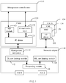
- a virtualization system generally includes a management control center 110, a VMM 120, one or more VMs 130, a network adapter 140, and the like.
- the management control center 110 may manage and control the entire virtualization system and deliver various instructions or policies.
- the VMM 120 may include an application programming interface (application programming interface, API) module 121, a virtualization layer 122, and a PF driver 123.
- API application programming interface
- a user may create a VM by using the virtualization layer 122. Further, the user may interact with the PF driver by using the API module 121, invoke a related interface of the PF driver to create a VF, and allocate the created VF to a corresponding VM.
- the VM 130 may work like a real computer. For example, an application program and an operating system may be installed on the VM 130.
- the VM 130 may include a VF driver 131.
- the VM 130 may create a vNIC by using the VF driver 131. Assuming that the VF driver 131 is corresponding to a VF1 of the network adapter 140, a data packet of the vNIC created by the VF driver 131 may be transmitted by using a bandwidth resource corresponding to the VF1.
- the network adapter 140 includes a PF and a VF.
- the PF is a PCI function supported by the network adapter and may be extended as several VFs.
- a VF is an instance (instance) obtained by means of virtualization performed by an SRIOV-supported network adapter.
- a bandwidth resource for data transmission is configured for each VF of the network adapter.
- Each VF is allocated by the VMM to the VM running on the host device.
- the network adapter 140 may include a management subsystem 141 that may be used to interact with the PF driver and the VF driver.
- the management subsystem 141 may be, for example, a central processing unit (central processing unit, CPU) or another type of processing unit.
- the network adapter 140 may further include a TX rate limiting module 142, an RX rate limiting module 143, and a forwarding module 144.
- the TX rate limiting module 142 may be a module in a hardware form.
- the TX rate limiting module 142 may be configured to limit a rate of traffic in a TX direction.
- the TX direction is a direction from a vNIC to outside (another vNIC of a same host device or another host device).
- the RX rate limiting module 143 may be a module in a hardware form.
- the RX rate limiting module 143 may be configured to limit a rate of traffic in an RX direction.
- the RX direction is a direction from the outside to a vNIC.
- the forwarding module 144 may be a module in a hardware form.
- the forwarding module 144 may include a forwarding information table.
- the network adapter may forward, based on the forwarding information table in the forwarding module 144, a data packet between different host devices or between different vNICs of a same host device.
- the VMM 120 and the VM 130 may run on a host device connected to the network adapter 140, and the management control center 110 may run on the host device or another host device.
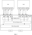
- multiple vNICs may be configured (or created) for one VM.
- a network adapter configures one VF for each of the multiple vNICs.
- a vNIC1, a vNIC2, and a vNIC3 are configured for a VM1.
- a VF1, a VF2, and a VF3 are configured for the network adapter, and are corresponding to the vNIC1, the vNIC2, and the vNIC3 of the VM1 respectively.
- a vNIC4, a vNIC5, and a vNIC6 are configured for a VM2, and a VF4, a VF5, and a VF6 are configured for the network adapter, and are corresponding to the vNIC4, the vNIC5, and the vNIC6 of the VM2 respectively.
- Each VF of the network adapter has independent PCI configuration space (or PCIe configuration space) and PCI memory space (the PCI memory space may also be referred to as PCIe memory space or BAR space).
- the PCI memory space of the VF stores control information of a queue, and the network adapter may forward, according to the control information of the queue, a data packet of a vNIC corresponding to the VF.
- the VF1 in FIG. 2 is used as an example.
- the network adapter configures a queue pair for the VF1 to forward a data packet of the vNIC1.
- the queue pair includes a sending queue (sending queue, SQ) and a receiving queue (receiving queue, RQ).
- Control information of the SQ and the RQ is stored in PCI memory space of the VF1.
- the network adapter obtains the control information of the SQ and the RQ from the PCI memory space of the VF1, and controls, based on the control information of the SQ and the RQ, the process of forwarding the data packet of the vNIC1.
- the queues may be further used to buffer the data packets to be forwarded. The following describes in detail the process of forwarding the data packet of the vNIC1 with reference to FIG. 3 .
- the SQ is used as an example.
- a network adapter side is mainly used to store the control information of the SQ (which is specifically stored in PCI memory space of a VF).
- the control information of the SQ includes a base address (base address) of the queue, a head (head) address of the queue, a tail (tail) address of the queue, and a length (length) of the queue.
- a host device side is mainly used to store the SQ and a data packet.
- each storage unit of the SQ is configured to store a buffer descriptor (buffer description, BD).
- the BD includes information about a data packet, such as a storage location of the data packet in a memory of the host device and a size of the data packet (PKT BUF in FIG. 3 represents the memory in which the data packet is stored, and a location of the memory is described or indicated by the BD).
- PKT BUF in FIG. 3 represents the memory in which the data packet is stored, and a location of the memory is described or indicated by the BD.
- the network adapter parses the BD to obtain a storage location of the to-be-forwarded data packet in the memory of the host device.
- the network adapter obtains the to-be-forwarded data packet from the memory by means of direct memory access (Direct Memory Access, DMA), and forwards the to-be-forwarded data packet.
- DMA Direct Memory Access
- a processing process of the RQ is approximately similar to that of the SQ, except that instead of reading a data packet from the memory of the host device by means of DMA, the network adapter needs to store the data packet in the memory of the host device by means of DMA and update a BD in a queue tail of the RQ. To avoid repetition, details are not described herein again.
- the network adapter configures one or multiple queue pairs for each VF.
- Each VF serves only one vNIC, that is, queues of each VF are used to forward a data packet of only one vNIC, and there is a one-to-one correspondence between a VF and a vNIC.
- a virtual switch function is provided and a bandwidth limiting function can be provided by using the PF/VF.
- a user may allocate a bandwidth resource to each VF by using the bandwidth limiting function.
- Bandwidth is an amount of data transmitted per unit of time, for example, a quantity of data packets that can be transmitted within one second.
- a bandwidth resource of each VF may be bandwidth occupied by a data packet forwarded by using queues of each VF, such as average bandwidth, peak bandwidth, or burst bandwidth.
- a rate limiting manner based on a token bucket technology is used as an example.
- the bandwidth resource of each VF may be controlled according to a token bucket type and a token quantity that are allocated to each VF by a rate limiting module of the network adapter.
- Each VF is corresponding to one vNIC, and therefore, bandwidth allocated to each VF is exclusively used by one vNIC and the bandwidth resource cannot be shared among multiple vNICs.
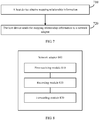
- FIG. 4 is a schematic flowchart of a data packet forwarding method according to an embodiment of the present invention.
- the method in FIG. 4 may be applied to a network adapter.
- the method in FIG. 4 may be implemented by a network adapter.
- the network adapter may be connected to a host device (which may be, for example, a server).
- the host device includes a first VM, and the first VM may include N vNICs, where N is an integer greater than 1.
- the network adapter includes a first VF allocated to the first VM.
- a specific allocation process may be implemented by a VMM on the host device.
- the network adapter (including a network adapter or a virtual network adapter) in this embodiment of the present invention may also be referred to as a network interface card or a network adapter.
- the method in FIG. 4 includes the following steps.
- the network adapter receives mapping relationship information sent by the host device, where the mapping relationship information is used to indicate a one-to-one mapping relationship between N queue pairs among queues configured for the first VF and the N vNICs, and each of the N queue pairs is used to forward a data packet of a vNIC corresponding to each queue pair.
- the mapping relationship information may be generated by the management control center 110 at an upper layer and delivered to the forwarding module 144 of the network adapter by using a driver of the first VM running on the host device.
- the network adapter configures X queue pairs for the first VF (X is a positive integer not less than N).
- X represents a maximum quantity of queues that can be configured for the first VF (that is, a maximum quantity of configurable queue pairs).
- X may be a system default value, and the system default value may be pre-stored in the management subsystem 141 shown in FIG. 1 .
- a data packet of a vNIC may be a data packet that is sent to the vNIC or a data packet that needs to be forwarded by the vNIC.
- the data packet of the vNIC may be a data packet whose destination address is a MAC address of the vNIC and/or may be a data packet whose source address is the MAC address of the vNIC.
- the network adapter records the mapping relationship information in a forwarding information table of the network adapter.
- the network adapter forwards data packets of the N vNICs according to the mapping relationship information recorded in the forwarding information table.
- the network adapter includes the forwarding information table that is used to record the mapping relationship information. As shown in FIG. 1 , the network adapter 140 includes the forwarding module 144, and the forwarding module 144 forwards a data packet based on the mapping relationship information recorded in the forwarding information table.
- one VF is corresponding to one vNIC, and therefore, queues of the VF are used to forward a data packet of only one vNIC.
- the one-to-one mapping relationship is established between the N queue pairs of the first VF and the N vNICs of the first VM. That is, queues of the first VF may be used to forward the data packets of the N vNICs.
- the mapping relationship information is stored in the forwarding information table of the network adapter.
- the data packets of the N vNICs need to be forwarded based on the forwarding information table provided in this embodiment of the present invention
- the data packets of the N vNICs are all forwarded by using the queues of the first VF. Because the network adapter allocates a bandwidth resource on a basis of a VF, the N vNICs can share a bandwidth resource of the first VF.
- the N vNICs may be some or all vNICs of the first VM, and this is not specifically limited in this embodiment of the present invention.
- the N vNICs may be all vNICs of the first VM, and it is equivalent that the first VF serves the entire first VM and all the vNICs of the first VM can share the bandwidth resource of the first VF.
- the above-mentioned first VM may be either a VM1 or a VM2 in FIG. 5 . It is assumed that the first VM is the VM1, the first VF is a VF1 in FIG. 5 , and the VM1 includes three vNICs: a vNIC1, a vNIC2, and a vNIC3.
- a sending queue SQ1 and a receiving queue RQ1 that are responsible for forwarding a data packet of the vNIC1, a sending queue SQ2 and a receiving queue RQ2 that are responsible for forwarding a data packet of the vNIC2, and a sending queue SQ3 and a receiving queue RQ3 that are responsible for forwarding a data packet of the vNIC3 are configured for the VF1. Therefore, it is equivalent that the VF1 serves the entire VM1 instead of serving only one vNIC as described in the prior art. In this case, all the three vNICs of the VM1 can share a bandwidth resource of the VF1.
- FIG. 5 illustrates an example in which one VF is corresponding to all vNICs of a VM, but this is not limited in this embodiment of the present invention.
- the VF1 in FIG. 5 may be corresponding to some vNICs of the VM1.
- the VF1 is corresponding to only the vNIC1 and the vNIC2 of the VM1.
- FIG. 5 illustrates only an example in which the VM1 (or the VM2) includes three vNICs. Actually, the VM1 may include two, four, or even more vNICs.
- mapping relationship information is not specifically limited provided that a queue corresponding to a data packet to be sent or to be received can be found based on the mapping relationship information.
- the mapping relationship information may record an identifier of each of the N vNICs, an identifier of a VF corresponding to each vNIC, and an identifier of a queue corresponding to each vNIC.
- the identifier of each of the N vNICs may include a Media Access Control (media access control, MAC) address and a virtual local area network (virtual local area network, VLAN) identifier of each vNIC.
- MAC media access control
- VLAN virtual local area network
- the mapping relationship information may be expressed in a table form, and in this case, the mapping relationship information may also be called a mapping relationship table.
- Table 1 is an example of the mapping relationship table. Each line of Table 1 records a MAC address and a VLAN identifier of a vNIC, an identifier of a VF corresponding to the vNIC, and an identifier of a queue pair (including a sending queue and a receiving queue) corresponding to the vNIC.
- the method in FIG. 4 may further include: before the first VM is started, receiving, by the network adapter (which may be specifically a management subsystem of the network adapter), first indication information from a PF driver of the network adapter, where the first indication information is used to indicate that a quantity of queues that need to be started for the first VF is N; and during a process of starting the first VM, sending, by the network adapter (which may be specifically the management subsystem of the network adapter), second indication information to a driver of the first VF running on the first VM, where the second indication information is used to indicate that a quantity of queues started for the first VF is N, so as to trigger the driver of the first VF to create N vNICs.
- a user may operate the management control center 110 and configure, by using the API module 121 of the VMM 120, a quantity M of vNICs required by the first VM (where M is a positive integer greater than or equal to N). Then, the API module 121 may send the first indication information to the management subsystem 141 of the network adapter according to the quantity of vNICs required by the first VM, so as to instruct the first VF to start or enable N queue pairs. Each of the N queue pairs may be corresponding to one vNIC.
- the management subsystem 141 may record the quantity N of queues started for the first VF.
- the management subsystem 141 of the network adapter 140 sends the second indication information to the driver of the first VF, and the driver of the first VF creates the N vNICs according to the second indication information.
- one VF is corresponding to one vNIC, and therefore, the driver of the first VF directly creates one vNIC during the process of starting the first VM.
- the first VF is corresponding to multiple vNICs of the first VM. Therefore, during the process of starting the first VM, the driver of the first VF may learn, from the network adapter (which may be specifically the management subsystem of the network adapter), the quantity of queues started for the first VF, so as to learn a quantity of vNICs that need to be created by the driver of the first VF, and then create vNICs of the corresponding quantity.
- the network adapter which may be specifically the management subsystem of the network adapter
- step 430 may include: receiving a first data packet, where the first data packet is a data packet sent to a first vNIC of the N vNICs, and the first data packet includes an identifier of the first vNIC; determining, by querying for the mapping relationship information in the forwarding information table according to the identifier of the first vNIC, a target receiving queue that is of the first VF and that is corresponding to the first vNIC; obtaining control information of the target receiving queue from PCI memory space of the first VF; and sending, according to the control information of the target receiving queue, the first data packet to the first vNIC by using the target receiving queue.
- a data packet may be stored at a corresponding location in a memory of the host device by means of DMA according to control information of a queue, and then the data packet is sent or received.
- DMA control information of a queue
- the mapping relationship information may be used for a data packet exchange between different VMs of a same host device, or a data packet exchange between a VM and another host device.
- Table 1 is used as an example. Assuming that the network adapter receives a data packet 1, and a MAC address and a VLAN identifier of the data packet 1 are 00:11:22:33:55:66 and 1 respectively, the network adapter can find, by searching Table 1, a VF identifier 2 (referred to as a VF2 below) and a queue identifier 1 (referred to as a queue 1 below) that are corresponding to the MAC address and the VLAN identifier. Then, the network adapter can obtain control information of an RQ in the queue 1 from PCI memory space of the VF2, and forward, according to the control information of the RQ, the data packet 1 to a vNIC corresponding to the queue 1.
- VF2 VF identifier 2
- queue identifier 1 referred to as a queue 1 below
- a bandwidth limitation function of the network adapter is designed for a VF/PF. Therefore, the bandwidth limitation function can be implemented by adjusting bandwidth corresponding to the VF.
- one VF is corresponding to one vNIC, and therefore, limiting bandwidth of a VF is equivalent to limiting a rate of traffic of one vNIC.
- a cloud computing vendor may provide only vNIC-based rate limiting and charging policies, which are too simple to meet diversified needs.
- each VF may be corresponding to multiple vNICs of a VM, and therefore, limiting bandwidth of a VF is equivalent to limiting a rate of overall traffic of multiple vNICs of a VM.
- the cloud computing vendor may formulate rate limiting and charging policies for overall traffic of multiple vNICs, so that the rate limiting and charging policies are more flexible and diversified.
- the method in FIG. 4 may further include: receiving, by the network adapter (which may be specifically the management subsystem of the network adapter), rate limiting policy information from the PF driver of the network adapter, where the rate limiting policy information may be used to indicate an overall rate limiting policy for the N vNICs of the first VM; and configuring, by the network adapter (which may be specifically the management subsystem of the network adapter) according to the overall rate limiting policy, a bandwidth resource corresponding to the first VF.
- the network adapter which may be specifically the management subsystem of the network adapter
- the user may deliver the rate limiting policy information by operating the management control center.
- the user may send the rate limiting policy information to the PF driver 123 by using the API module 121, and then send the rate limiting policy information to the management subsystem 141 by using the PF driver 123.
- the management subsystem 141 may store various configuration parameters in the rate limiting policy information, and perform rate limiting by using the TX rate limiting module 142 and the RX rate limiting module 143.
- a specific rate limiting manner may be rate limitation based on a token bucket technology.
- a double-rate and double-bucket algorithm is used to control the TX rate limiting module and the RX rate limiting module in a hardware form to perform rate limiting.
- a rate limiting manner based on the token bucket technology refer to the prior art. Details are not described herein.
- the rate limiting policy information may include at least one of rate limiting policy information specific to a TX direction or rate limiting policy information specific to an RX direction.
- the rate limiting policy information specific to the TX direction may include at least one of following information: a committed information rate (committed information rate, CIR), average bandwidth, a peak information rate (peak information rate, PIR), peak bandwidth, a peak burst size (peak burst size, PBS), burst traffic, or the like.
- the rate limiting policy information specific to the RX direction may include at least one of the following information: average bandwidth, peak bandwidth, or burst bandwidth.
- the N vNICs may be all vNICs of the first VM.
- the cloud computing vendor may formulate rate limiting and charging policies for overall traffic of the first VM.
- FIG. 6 illustrates an example in which the first VF is corresponding to all vNICs of the first VM, but this is not limited in this embodiment of the present invention and the first VF may be corresponding to some vNICs of the first VM.
- FIG. 6 is a schematic flowchart of a data packet forwarding method according to an embodiment of the present invention.
- the network adapter allocates PCI memory space (or referred to as BAR space) to a first VF according to a maximum quantity of queues that can be configured for the first VF.
- PCI memory space or referred to as BAR space
- step 610 may be performed by a PF of the network adapter.
- the first VF may be any one VF of the network adapter.
- the maximum quantity of queues that can be configured for the first VF may be a default value.
- the default value may be managed and maintained by, for example, a management subsystem of the network adapter. Therefore, the default value may be obtained from the management subsystem during startup of the network adapter. The following description assumes that a maximum of X queue pairs can be configured for the first VF.
- the PCI memory space of the first VF may include X storage areas in a one-to-one correspondence to the X queue pairs. Each storage area is used to store control information of one queue pair. Control information of a queue may include a base address, a length, a head address, a tail address, and the like of the queue.
- a host device creates a first VM and allocates the first VF to the first VM.
- Step 620 may be specifically performed by a VMM on the host device.
- a user or an administrator may operate the management control center 110, so that the virtualization layer 122 of the VMM 120 creates the first VM and allocates the first VF to the first VM.
- a management control center delivers a quantity of vNICs that need to be configured for the first VM.
- the user may operate the management control center 110 to configure, by using the API module 121, the quantity of vNICs required by the first VM.
- the API module 121 delivers first indication information to the management subsystem 141 of the network adapter 140, indicating that a quantity of queues that need to be started for the first VF is N.
- the management subsystem 141 records the quantity of queues that need to be started for the first VF and an identifier of the first VF.
- the host device starts the first VM and loads a driver of the first VF.
- Step 640 may be specifically performed by the VMM on the host device.
- the driver of the first VF interacts with the management subsystem to obtain a quantity of queues started for the first VF.
- the driver of the first VF may create a same quantity of vNICs according to the quantity of queues started for the first VF.
- the host device sends, to the network adapter, mapping relationship information delivered by the management control center.
- the mapping relationship information may be generated by the management control center, and delivered to the network adapter by using the host device (which may be specifically a driver of a first VM running on a first host device).
- the mapping relationship information may include a mapping relationship among a MAC address and a VLAN identifier of each virtual network adapter corresponding to the first VF, a VF identifier, and a queue identifier (for details, refer to Table 1).
- the network adapter may record the mapping relationship information in a forwarding information table.
- the management control center configures a rate limiting policy for the first VM.
- step 660 and steps 610 to 650 is not specifically limited in this embodiment of the present invention.
- the rate limiting policy for the first VM may be configured before or after the first VM is started.
- the user may operate the management control center to deliver rate limiting policy information (indicating an overall rate limiting policy of the first VM) to the API module 121.
- the API module 121 may deliver the rate limiting policy information to the management subsystem 141 by using the PF driver 123.
- the management subsystem 141 stores the rate limiting policy information and limits, according to the rate limiting policy information, rates of traffic in a TX direction and an RX direction of the first VM respectively by using the TX rate limiting module 142 and the RX rate limiting module 143 of the network adapter 140.
- a specific rate limiting manner may be implemented by using a token bucket technology or another technology, and is not specifically limited in this embodiment of the present invention.
- one VF is corresponding to one vNIC, and therefore, the user can formulate a rate limiting policy specific to only one vNIC.
- a VF is corresponding to all vNICs of a VM, and therefore, the user can formulate a rate limiting policy specific to a VM.
- Table 2 is an example of a rate liming policy for a VM.
- Table 2 Example of a rate liming policy for a VM VM identifier Average bandwidth (TX) Peak bandwidth (TX) Burst traffic (TX) Average bandwidth (RX) Peak bandwidth (RX) Burst bandwidth (RX) 1 100 Mbps 120 Mbps 200 Mbits 100 Mbps 120 Mbps 200 Mbits 2 120 Mbps 140 Mbps 200 Mbits 120 Mbps 140 Mbps 200 Mbits
- the network adapter forwards data packets of the vNICs of the first VM according to the mapping relationship information recorded in a forwarding information table and the configured rate limiting policy.
- Step 670 may be specifically implemented by a forwarding module of the network adapter.
- the mapping relationship information may be recorded in a forwarding information table of the forwarding module. Regardless of whether a data packet is received from a network side or different VMs of a same host device, a corresponding queue may be found by querying for the mapping relationship information in the forwarding information table according to a MAC address and a VLAN identifier of a vNIC that are recorded in the data packet, and the data packet is sent to the vNIC that is of the first VM and that is corresponding to the queue. If no corresponding queue is found, the data packet may be broadcast.
- rate limiting can be performed on overall traffic of a VM. This helps a VM user balance traffic of vNICs of the VM.
- a cloud provider can perform charging on the overall traffic of the VM. This enriches charging policies of the cloud provider.
- FIG. 7 is a schematic flowchart of a data packet forwarding method according to an embodiment of the present invention.
- the method in FIG. 7 may be applied to a host device.
- the host device is connected to a network adapter, the host device includes a first VM, the first VM includes N vNICs, and the network adapter includes a first VF allocated to the first VM, where N is an integer greater than 1.
- the method in FIG. 7 includes the following steps.
- the host device obtains mapping relationship information, where the mapping relationship information is used to indicate a one-to-one mapping relationship between N queue pairs among queues configured for the first VF and the N vNICs, and each of the N queue pairs is used to forward a data packet of a vNIC corresponding to each queue pair.
- the mapping relationship information may be generated by the management control center 110 shown in FIG. 1 .
- Step 710 may specifically include: obtaining the mapping relationship information from the management control center 110.
- the host device sends the mapping relationship information to the network adapter, so that the network adapter records the mapping relationship information in a forwarding information table of the network adapter.
- the mapping relationship information records an identifier of each of the N vNICs, an identifier of a VF corresponding to each vNIC, and an identifier of a queue corresponding to each vNIC.
- the identifier of each of the N vNICs includes a MAC address and a VLAN identifier of each vNIC.
- the method in FIG. 7 may further include: before the first VM is started, sending first indication information to the network adapter by using a PF driver of the network adapter, where the first indication information is used to indicate that a quantity of queues that need to be started for the first VF is N; and during a process of starting the first VM, receiving second indication information sent to a driver of the first VF by the network adapter, where the second indication information is used to indicate that a quantity of queues started for the first VF is N, so as to trigger the driver of the first VF to create N vNICs.
- the method in FIG. 7 may further include: sending rate limiting policy information to the network adapter by using the PF driver of the network adapter, where the rate limiting policy information is used to indicate an overall rate limiting policy for the N vNICs of the first VM.
- FIG. 8 is a schematic structural diagram of a network adapter according to an embodiment of the present invention.
- a network adapter 800 in FIG. 8 is connected to a host device, the host device includes a first VM, the first VM includes N vNICs, and the network adapter 800 includes a first VF allocated to the first VM, where N is an integer greater than 1.
- the network adapter 800 includes:
- the one-to-one mapping relationship is established between the N queue pairs of the first VF and the N vNICs of the first VM, so that the data packets of the N vNICs are all forwarded by using queues of the first VF. Because the network adapter allocates a bandwidth resource on a basis of a VF, the N vNICs can share a bandwidth resource of the first VF.
- the mapping relationship information may record an identifier of each of the N vNICs, an identifier of a VF corresponding to each vNIC, and an identifier of a queue corresponding to each vNIC.
- the forwarding module 830 may be specifically configured to: receive a first data packet, where the first data packet is a data packet sent to a first vNIC of the N vNICs, and the first data packet includes an identifier of the first vNIC; determine, by querying for the mapping relationship information in the forwarding information table according to the identifier of the first vNIC, a target receiving queue that is of the first VF and that is corresponding to the first vNIC; obtain control information of the target receiving queue from PCI memory space of the first VF; and send, according to the control information of the target receiving queue, the first data packet to the first vNIC by using the target receiving queue.
- the identifier of each of the N vNICs may include a MAC address and a VLAN identifier of each vNIC.
- the network adapter 800 may further include: a second receiving module, configured to receive first indication information from a PF driver of the network adapter 800 before the first VM is started, where the first indication information is used to indicate that a quantity of queues that need to be started for the first VF is N; and a sending module, configured to send second indication information to a driver of the first VF during a process of starting the first VM, where the second indication information is used to indicate that a quantity of queues started for the first VF is N, so as to trigger the driver of the first VF to create N vNICs.
- a second receiving module configured to receive first indication information from a PF driver of the network adapter 800 before the first VM is started, where the first indication information is used to indicate that a quantity of queues that need to be started for the first VF is N
- a sending module configured to send second indication information to a driver of the first VF during a process of starting the first VM, where the second indication information is used to indicate that a quantity of queue
- the network adapter 800 may further include: a third receiving module, configured to receive rate limiting policy information from the PF driver of the network adapter 800, where the rate limiting policy information is used to indicate an overall rate limiting policy for the N vNICs of the first VM; and a configuration module, configured to configure, according to the overall rate limiting policy, a bandwidth resource corresponding to the first VF.
- a third receiving module configured to receive rate limiting policy information from the PF driver of the network adapter 800, where the rate limiting policy information is used to indicate an overall rate limiting policy for the N vNICs of the first VM
- a configuration module configured to configure, according to the overall rate limiting policy, a bandwidth resource corresponding to the first VF.
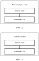
- FIG. 9 is a schematic structural diagram of a host device according to an embodiment of the present invention.
- a host device 900 in FIG. 9 is connected to a network adapter, the host device 900 includes a first VM, the first VM includes N vNICs, and the network adapter includes a first VF allocated to the first VM, where N is an integer greater than 1.
- the host device 900 includes:
- the one-to-one mapping relationship is established between the N queue pairs of the first VF and the N vNICs of the first VM, so that data packets of the N vNICs are all forwarded by using queues of the first VF. Because the network adapter allocates a bandwidth resource on a basis of a VF, the N vNICs can share a bandwidth resource of the first VF.
- the mapping relationship information may record an identifier of each of the N vNICs, an identifier of a VF corresponding to each vNIC, and an identifier of a queue corresponding to each vNIC.
- the identifier of each of the N vNICs may include a MAC address and a VLAN identifier of each vNIC.
- the host device 900 may further include: a second sending module, configured to: before the first VM is started, send first indication information to a PF driver of the network adapter, where the first indication information is used to indicate that a quantity of queues that need to be started for the first VF is N; and a receiving module, configured to: during a process of starting the first VM, receive second indication information sent to a driver of the first VF by the network adapter, where the second indication information is used to indicate that a quantity of queues started for the first VF is N, so as to trigger the driver of the first VF to create N vNICs.
- a second sending module configured to: before the first VM is started, send first indication information to a PF driver of the network adapter, where the first indication information is used to indicate that a quantity of queues that need to be started for the first VF is N
- a receiving module configured to: during a process of starting the first VM, receive second indication information sent to a driver of the first VF by the network
- the host device 900 may further include: a third sending module, configured to send rate limiting policy information to the network adapter by using the PF driver of the network adapter, where the rate limiting policy information is used to indicate an overall rate limiting policy for the N vNICs of the first VM.
- a third sending module configured to send rate limiting policy information to the network adapter by using the PF driver of the network adapter, where the rate limiting policy information is used to indicate an overall rate limiting policy for the N vNICs of the first VM.
- FIG. 10 is a schematic structural diagram of a computer system according to an embodiment of the present invention.
- a computer system 1000 in FIG. 10 includes the network adapter 800 shown in FIG. 8 and the host device 900 in FIG. 9 .
- FIG. 11 is a schematic structural diagram of a network adapter according to an embodiment of the present invention.
- a network adapter 1100 in FIG. 11 is connected to a host device, the host device includes a first VM, the first VM includes N vNICs, and the network adapter 1100 includes a first VF allocated to the first VM, where N is an integer greater than 1.
- the network adapter 1100 includes:
- the one-to-one mapping relationship is established between the N queue pairs of the first VF and the N vNICs of the first VM, so that the data packets of the N vNICs are all forwarded by using queues of the first VF. Because the network adapter allocates a bandwidth resource on a basis of a VF, the N vNICs can share a bandwidth resource of the first VF.
- the mapping relationship information may record an identifier of each of the N vNICs, an identifier of a VF corresponding to each vNIC, and an identifier of a queue corresponding to each vNIC.
- the forwarding data packets of the N vNICs according to the mapping relationship information recorded in the forwarding information table may include: receiving a first data packet, where the first data packet is a data packet sent to a first vNIC of the N vNICs, and the first data packet includes an identifier of the first vNIC; determining, by querying for the mapping relationship information in the forwarding information table according to the identifier of the first vNIC, a target receiving queue that is of the first VF and that is corresponding to the first vNIC; obtaining control information of the target receiving queue from PCI memory space of the first VF; and sending, according to the control information of the target receiving queue, the first data packet to the first vNIC by using the target receiving queue.
- the identifier of each of the N vNICs may include a MAC address and a VLAN identifier of each vNIC.
- the processor 1120 may be further configured to perform the following operations: receiving first indication information from a PF driver of the network adapter 1100 before the first VM is started, where the first indication information is used to indicate that a quantity of queues that need to be started for the first VF is N; and sending second indication information to a driver of the first VF during a process of starting the first VM, where the second indication information is used to indicate that a quantity of queues started for the first VF is N, so as to trigger the driver of the first VF to create N vNICs.
- the processor 1120 may be further configured to perform the following operations: receiving rate limiting policy information from the PF driver of the network adapter 1100, where the rate limiting policy information is used to indicate an overall rate limiting policy for the N vNICs of the first VM; and configuring, according to the overall rate limiting policy, a bandwidth resource corresponding to the first VF.
- FIG. 12 is a schematic structural diagram of a host device according to an embodiment of the present invention.
- a host device 1200 in FIG. 12 is connected to a network adapter, the host device 1200 includes a first VM, the first VM includes N vNICs, and the network adapter includes a first VF allocated to the first VM, where N is an integer greater than 1.
- the host device 1200 includes:
- the one-to-one mapping relationship is established between the N queue pairs of the first VF and the N vNICs of the first VM, so that data packets of the N vNICs are all forwarded by using queues of the first VF. Because the network adapter allocates a bandwidth resource on a basis of a VF, the N vNICs can share a bandwidth resource of the first VF.
- the mapping relationship information may record an identifier of each of the N vNICs, an identifier of a VF corresponding to each vNIC, and an identifier of a queue corresponding to each vNIC.
- the identifier of each of the N vNICs may include a MAC address and a VLAN identifier of each vNIC.
- the processor 1220 may be further configured to perform the following operations: before the first VM is started, sending first indication information to the network adapter by using a physical function PF driver of the network adapter, where the first indication information is used to indicate that a quantity of queues that need to be started for the first VF is N; and during a process of starting the first VM, receiving second indication information sent to a driver of the first VF by the network adapter, where the second indication information is used to indicate that a quantity of queues started for the first VF is N, so as to trigger the driver of the first VF to create N vNICs.
- the processor 1220 may be further configured to perform the following operation: sending rate limiting policy information to the network adapter by using the PF driver of the network adapter, where the rate limiting policy information is used to indicate an overall rate limiting policy for the N vNICs of the first VM.
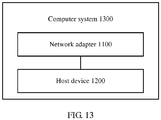
- FIG. 13 is a schematic structural diagram of a computer system according to an embodiment of the present invention.
- a computer system 1300 in FIG. 13 includes the network adapter 1100 in FIG. 11 and the host device 1200 in FIG. 12 .
Priority Applications (1)
| Application Number | Priority Date | Filing Date | Title |
|---|---|---|---|
| EP19219805.9A EP3693854A1 (fr) | 2017-01-20 | 2017-01-20 | Procédé de transfert de paquets de données, adaptateur de réseau, dispositif hôte et système informatique |
Applications Claiming Priority (1)
| Application Number | Priority Date | Filing Date | Title |
|---|---|---|---|
| PCT/CN2017/071951 WO2018133035A1 (fr) | 2017-01-20 | 2017-01-20 | Procédé, carte réseau, dispositif hôte et système informatique pour transférer des paquets de données |
Related Child Applications (2)
| Application Number | Title | Priority Date | Filing Date |
|---|---|---|---|
| EP19219805.9A Division EP3693854A1 (fr) | 2017-01-20 | 2017-01-20 | Procédé de transfert de paquets de données, adaptateur de réseau, dispositif hôte et système informatique |
| EP19219805.9A Division-Into EP3693854A1 (fr) | 2017-01-20 | 2017-01-20 | Procédé de transfert de paquets de données, adaptateur de réseau, dispositif hôte et système informatique |
Publications (3)
| Publication Number | Publication Date |
|---|---|
| EP3376376A4 EP3376376A4 (fr) | 2018-09-19 |
| EP3376376A1 true EP3376376A1 (fr) | 2018-09-19 |
| EP3376376B1 EP3376376B1 (fr) | 2020-03-11 |
Family
ID=59436508
Family Applications (2)
| Application Number | Title | Priority Date | Filing Date |
|---|---|---|---|
| EP17822109.9A Active EP3376376B1 (fr) | 2017-01-20 | 2017-01-20 | Procédé, carte réseau, dispositif hôte et système informatique pour transférer des paquets de données |
| EP19219805.9A Pending EP3693854A1 (fr) | 2017-01-20 | 2017-01-20 | Procédé de transfert de paquets de données, adaptateur de réseau, dispositif hôte et système informatique |
Family Applications After (1)
| Application Number | Title | Priority Date | Filing Date |
|---|---|---|---|
| EP19219805.9A Pending EP3693854A1 (fr) | 2017-01-20 | 2017-01-20 | Procédé de transfert de paquets de données, adaptateur de réseau, dispositif hôte et système informatique |
Country Status (5)
| Country | Link |
|---|---|
| US (3) | US10462056B2 (fr) |
| EP (2) | EP3376376B1 (fr) |
| CN (2) | CN111490949B (fr) |
| ES (1) | ES2787450T3 (fr) |
| WO (1) | WO2018133035A1 (fr) |
Families Citing this family (20)
| Publication number | Priority date | Publication date | Assignee | Title |
|---|---|---|---|---|
| CN108965169B (zh) * | 2018-07-12 | 2020-09-25 | 联想(北京)有限公司 | 一种报文传输方法、网卡控制器、网卡及电子设备 |
| US10853126B2 (en) * | 2018-07-26 | 2020-12-01 | Vmware, Inc. | Reprogramming network infrastructure in response to VM mobility |
| CN110825485A (zh) | 2018-08-07 | 2020-02-21 | 华为技术有限公司 | 数据处理的方法、设备和服务器 |
| CN110912825B (zh) * | 2018-09-18 | 2022-08-02 | 阿里巴巴集团控股有限公司 | 一种报文的转发方法、装置、设备及系统 |
| US10992601B2 (en) * | 2018-10-19 | 2021-04-27 | Gubernet Inc. | Packet processing method and apparatus in multi-layered network environment |
| CN109634723B (zh) * | 2018-12-20 | 2023-04-18 | 国网新疆电力有限公司信息通信公司 | 融合存载模块的通信方法及融合存载模块 |
| US10929169B2 (en) | 2019-01-24 | 2021-02-23 | Vmware, Inc. | Reprogramming network infrastructure in response to VM mobility |
| CN110750367B (zh) * | 2019-09-30 | 2023-03-17 | 超聚变数字技术有限公司 | 一种队列通信的方法、系统及相关设备 |
| US11115284B1 (en) * | 2020-03-31 | 2021-09-07 | Atlassian Pty Ltd. | Techniques for dynamic rate-limiting |
| US11822964B2 (en) * | 2020-06-03 | 2023-11-21 | Baidu Usa Llc | Data protection with static resource partition for data processing accelerators |
| US11374792B2 (en) * | 2020-08-14 | 2022-06-28 | Oracle International Corporation | Techniques for utilizing multiple network interfaces for a cloud shell |
| US11368306B2 (en) | 2020-08-14 | 2022-06-21 | Oracle International Corporation | Techniques for using signed nonces to secure cloud shells |
| US11327673B1 (en) | 2020-10-23 | 2022-05-10 | Oracle International Corporation | Techniques for persisting data across instances of a cloud shell |
| US11777848B2 (en) * | 2020-10-14 | 2023-10-03 | Oracle International Corporation | Scalable routing and forwarding of packets in cloud infrastructure |
| US20220129293A1 (en) * | 2020-10-28 | 2022-04-28 | Red Hat, Inc. | Process isolation using virtual machine monitor tools to dynamically allocate compact virtual machines |
| CN112671561B (zh) * | 2020-12-11 | 2022-05-17 | 苏州浪潮智能科技有限公司 | 一种云主机的网卡配置的方法和设备 |
| US11470007B2 (en) * | 2021-01-19 | 2022-10-11 | Mellanox Technologies, Ltd. | Bandwidth-control policers in a network adapter |
| US11736558B2 (en) | 2021-10-29 | 2023-08-22 | Oracle International Corporation | Transparent mounting of external endpoints between private networks |
| US11558245B1 (en) | 2021-10-29 | 2023-01-17 | Oracle International Corporation | Secure bi-directional network connectivity system between private networks |
| CN115442183B (zh) * | 2022-08-02 | 2024-01-02 | 天翼云科技有限公司 | 一种数据转发方法及装置 |
Family Cites Families (37)
| Publication number | Priority date | Publication date | Assignee | Title |
|---|---|---|---|---|
| US20090055831A1 (en) * | 2007-08-24 | 2009-02-26 | Bauman Ellen M | Allocating Network Adapter Resources Among Logical Partitions |
| US7983257B2 (en) * | 2008-07-18 | 2011-07-19 | Emulex Design & Manufacturing Corporation | Hardware switch for hypervisors and blade servers |
| US8537860B2 (en) * | 2009-11-03 | 2013-09-17 | International Business Machines Corporation | Apparatus for switching traffic between virtual machines |
| US8315156B2 (en) * | 2010-06-30 | 2012-11-20 | Oracle America, Inc. | Method and system for distributing network traffic among multiple direct hardware access datapaths |
| US8417800B2 (en) * | 2010-07-16 | 2013-04-09 | Broadcom Corporation | Method and system for network configuration and/or provisioning based on open virtualization format (OVF) metadata |
| US8881141B2 (en) * | 2010-12-08 | 2014-11-04 | Intenational Business Machines Corporation | Virtualization of hardware queues in self-virtualizing input/output devices |
| US8913613B2 (en) * | 2011-02-16 | 2014-12-16 | Oracle International Corporation | Method and system for classification and management of inter-blade network traffic in a blade server |
| US8533713B2 (en) * | 2011-03-29 | 2013-09-10 | Intel Corporation | Efficent migration of virtual functions to enable high availability and resource rebalance |
| US8761187B2 (en) * | 2011-06-14 | 2014-06-24 | Futurewei Technologies, Inc. | System and method for an in-server virtual switch |
| CN103621048B (zh) * | 2011-07-11 | 2016-08-17 | 甲骨文国际公司 | 在中间件机器环境中利用多播组和分组处理代理中的至少一种来支持泛洪机制的系统与方法 |
| US8867403B2 (en) * | 2011-08-18 | 2014-10-21 | International Business Machines Corporation | Virtual network overlays |
| US9092274B2 (en) * | 2011-12-07 | 2015-07-28 | International Business Machines Corporation | Acceleration for virtual bridged hosts |
| EP2829024B1 (fr) * | 2012-03-19 | 2020-07-08 | Intel Corporation | Techniques de gestion de paquets dans un système de virtualisation d'entrée/sortie |
| US9612877B1 (en) * | 2012-07-12 | 2017-04-04 | Cisco Technology, Inc. | High performance computing in a virtualized environment |
| US9727386B2 (en) * | 2012-10-12 | 2017-08-08 | Futurewei Technologies, Inc. | Method and apparatus for network resource virtual partitioning |
| US9571507B2 (en) * | 2012-10-21 | 2017-02-14 | Mcafee, Inc. | Providing a virtual security appliance architecture to a virtual cloud infrastructure |
| CN102932174B (zh) | 2012-10-25 | 2015-07-29 | 华为技术有限公司 | 一种物理网卡管理方法、装置及物理主机 |
| US9083550B2 (en) * | 2012-10-29 | 2015-07-14 | Oracle International Corporation | Network virtualization over infiniband |
| CN102946366B (zh) * | 2012-11-12 | 2015-12-16 | 杭州华为数字技术有限公司 | 带内管理方法及系统 |
| US9008097B2 (en) * | 2012-12-31 | 2015-04-14 | Mellanox Technologies Ltd. | Network interface controller supporting network virtualization |
| US9602334B2 (en) * | 2013-01-22 | 2017-03-21 | International Business Machines Corporation | Independent network interfaces for virtual network environments |
| WO2014161133A1 (fr) * | 2013-04-01 | 2014-10-09 | 华为技术有限公司 | Procédé, appareil et système d'échange de données pour machine virtuelle |
| CN103414535B (zh) * | 2013-07-31 | 2017-04-19 | 华为技术有限公司 | 数据发送方法和数据接收方法及相关装置 |
| US9288135B2 (en) * | 2013-12-13 | 2016-03-15 | International Business Machines Corporation | Managing data flows in software-defined network using network interface card |
| US9548890B2 (en) * | 2014-03-17 | 2017-01-17 | Cisco Technology, Inc. | Flexible remote direct memory access resource configuration in a network environment |
| JPWO2015141337A1 (ja) * | 2014-03-19 | 2017-04-06 | 日本電気株式会社 | 受信パケット分散方法、キュー選択器、パケット処理装置、プログラム、およびネットワークインタフェースカード |
| US9594584B2 (en) * | 2014-03-31 | 2017-03-14 | Electronics And Telecommunications Research Institute | Apparatus and method for mapping of tenant based dynamic processor |
| US9537797B2 (en) * | 2014-06-13 | 2017-01-03 | Vmware, Inc. | MTU management in a virtualized computer system |
| US9699060B2 (en) * | 2014-12-17 | 2017-07-04 | Vmware, Inc. | Specializing virtual network device processing to avoid interrupt processing for high packet rate applications |
| US10216533B2 (en) * | 2015-10-01 | 2019-02-26 | Altera Corporation | Efficient virtual I/O address translation |
| US20170180325A1 (en) * | 2015-12-22 | 2017-06-22 | Intel Corporation | Technologies for enforcing network access control of virtual machines |
| CN106982133B (zh) * | 2016-01-18 | 2020-12-29 | 中兴通讯股份有限公司 | 一种更改虚拟网卡配置信息的方法、设备及系统 |
| CN107181679A (zh) * | 2016-03-09 | 2017-09-19 | 中兴通讯股份有限公司 | 一种端口绑定实现方法及装置 |
| US10178054B2 (en) * | 2016-04-01 | 2019-01-08 | Intel Corporation | Method and apparatus for accelerating VM-to-VM network traffic using CPU cache |
| US10547588B2 (en) * | 2016-04-30 | 2020-01-28 | Nicira, Inc. | Method of translating a logical switch into a set of network addresses |
| US10423437B2 (en) * | 2016-08-17 | 2019-09-24 | Red Hat Israel, Ltd. | Hot-plugging of virtual functions in a virtualized environment |
| EP3559806B1 (fr) * | 2016-12-22 | 2022-08-31 | INTEL Corporation | Accélération d'interface réseau de paravirtualisation à l'aide de remappage d'accès direct à la mémoire (dma) |
-
2017
- 2017-01-20 EP EP17822109.9A patent/EP3376376B1/fr active Active
- 2017-01-20 WO PCT/CN2017/071951 patent/WO2018133035A1/fr unknown
- 2017-01-20 EP EP19219805.9A patent/EP3693854A1/fr active Pending
- 2017-01-20 CN CN202010186245.3A patent/CN111490949B/zh active Active
- 2017-01-20 ES ES17822109T patent/ES2787450T3/es active Active
- 2017-01-20 CN CN201780000340.6A patent/CN107005495B/zh active Active
-
2018
- 2018-01-12 US US15/870,080 patent/US10462056B2/en active Active
-
2019
- 2019-10-09 US US16/597,581 patent/US11252087B2/en active Active
-
2021
- 2021-12-17 US US17/554,995 patent/US11805058B2/en active Active
Also Published As
| Publication number | Publication date |
|---|---|
| CN111490949B (zh) | 2022-07-29 |
| US10462056B2 (en) | 2019-10-29 |
| CN111490949A (zh) | 2020-08-04 |
| EP3693854A1 (fr) | 2020-08-12 |
| EP3376376A4 (fr) | 2018-09-19 |
| US20220109628A1 (en) | 2022-04-07 |
| US20180212875A1 (en) | 2018-07-26 |
| US20200044968A1 (en) | 2020-02-06 |
| ES2787450T3 (es) | 2020-10-16 |
| US11252087B2 (en) | 2022-02-15 |
| CN107005495B (zh) | 2020-03-27 |
| CN107005495A (zh) | 2017-08-01 |
| EP3376376B1 (fr) | 2020-03-11 |
| US11805058B2 (en) | 2023-10-31 |
| WO2018133035A1 (fr) | 2018-07-26 |
Similar Documents
| Publication | Publication Date | Title |
|---|---|---|
| US11805058B2 (en) | Data packet forwarding method, network adapter, host device, and computer system | |
| US11467885B2 (en) | Technologies for managing a latency-efficient pipeline through a network interface controller | |
| US20220197685A1 (en) | Technologies for application-specific network acceleration with unified coherency domain | |
| US10411971B2 (en) | Method for unified communication of server, baseboard management controller, and server | |
| EP3343364B1 (fr) | Procédé et appareil de virtualisation d'accélérateur, et gestionnaire de ressources centralisé | |
| US9264384B1 (en) | Resource virtualization mechanism including virtual host bus adapters | |
| US8634294B2 (en) | Discovery and capability exchange management in a virtualized computing platform | |
| US8503468B2 (en) | PCI express load sharing network interface controller cluster | |
| EP3629162B1 (fr) | Technologies de séparation de plan de commande au niveau d'un contrôleur d'interface réseau | |
| EP3076296A1 (fr) | Ordinateur, dispositif de commande et procédé de traitement de données | |
| US11593134B2 (en) | Throttling CPU utilization by implementing a rate limiter | |
| US20170180325A1 (en) | Technologies for enforcing network access control of virtual machines | |
| US20220300448A1 (en) | Peripheral component interconnect express device and method of operating the same | |
| WO2021120933A1 (fr) | Procédé et appareil de réglage de ressource | |
| US9317678B2 (en) | System and method for managing logins in a network interface | |
| WO2018057165A1 (fr) | Technologies de transition dynamique de files d'attente de tampon d'hôte de trafic de réseau | |
| EP4319057A1 (fr) | Système de gestion de noeuds informatiques, et procédé de gestion pour noeuds informatiques multiples | |
| EP4175247A1 (fr) | Procédé, appareil et système de transmission de paquets, et support de stockage |
Legal Events
| Date | Code | Title | Description |
|---|---|---|---|
| STAA | Information on the status of an ep patent application or granted ep patent |
Free format text: STATUS: UNKNOWN |
|
| STAA | Information on the status of an ep patent application or granted ep patent |
Free format text: STATUS: THE INTERNATIONAL PUBLICATION HAS BEEN MADE |
|
| PUAI | Public reference made under article 153(3) epc to a published international application that has entered the european phase |
Free format text: ORIGINAL CODE: 0009012 |
|
| STAA | Information on the status of an ep patent application or granted ep patent |
Free format text: STATUS: REQUEST FOR EXAMINATION WAS MADE |
|
| 17P | Request for examination filed |
Effective date: 20180110 |
|
| A4 | Supplementary search report drawn up and despatched |
Effective date: 20180803 |
|
| AK | Designated contracting states |
Kind code of ref document: A1 Designated state(s): AL AT BE BG CH CY CZ DE DK EE ES FI FR GB GR HR HU IE IS IT LI LT LU LV MC MK MT NL NO PL PT RO RS SE SI SK SM TR |
|
| AX | Request for extension of the european patent |
Extension state: BA ME |
|
| STAA | Information on the status of an ep patent application or granted ep patent |
Free format text: STATUS: EXAMINATION IS IN PROGRESS |
|
| 17Q | First examination report despatched |
Effective date: 20190328 |
|
| REG | Reference to a national code |
Ref country code: DE Ref legal event code: R079 Ref document number: 602017013068 Country of ref document: DE Free format text: PREVIOUS MAIN CLASS: G06F0009455000 Ipc: H04L0012460000 |
|
| RIC1 | Information provided on ipc code assigned before grant |
Ipc: H04L 12/935 20130101ALI20190709BHEP Ipc: H04L 12/46 20060101AFI20190709BHEP Ipc: G06F 9/455 20180101ALI20190709BHEP Ipc: H04L 12/741 20130101ALI20190709BHEP Ipc: H04L 12/815 20130101ALI20190709BHEP |
|
| GRAP | Despatch of communication of intention to grant a patent |
Free format text: ORIGINAL CODE: EPIDOSNIGR1 |
|
| STAA | Information on the status of an ep patent application or granted ep patent |
Free format text: STATUS: GRANT OF PATENT IS INTENDED |
|
| DAV | Request for validation of the european patent (deleted) | ||
| DAX | Request for extension of the european patent (deleted) | ||
| INTG | Intention to grant announced |
Effective date: 20190821 |
|
| GRAS | Grant fee paid |
Free format text: ORIGINAL CODE: EPIDOSNIGR3 |
|
| GRAA | (expected) grant |
Free format text: ORIGINAL CODE: 0009210 |
|
| STAA | Information on the status of an ep patent application or granted ep patent |
Free format text: STATUS: THE PATENT HAS BEEN GRANTED |
|
| AK | Designated contracting states |
Kind code of ref document: B1 Designated state(s): AL AT BE BG CH CY CZ DE DK EE ES FI FR GB GR HR HU IE IS IT LI LT LU LV MC MK MT NL NO PL PT RO RS SE SI SK SM TR |
|
| REG | Reference to a national code |
Ref country code: GB Ref legal event code: FG4D |
|
| REG | Reference to a national code |
Ref country code: CH Ref legal event code: EP |
|
| REG | Reference to a national code |
Ref country code: AT Ref legal event code: REF Ref document number: 1244529 Country of ref document: AT Kind code of ref document: T Effective date: 20200315 |
|
| REG | Reference to a national code |
Ref country code: IE Ref legal event code: FG4D |
|
| REG | Reference to a national code |
Ref country code: DE Ref legal event code: R096 Ref document number: 602017013068 Country of ref document: DE |
|
| REG | Reference to a national code |
Ref country code: NL Ref legal event code: FP |
|
| PG25 | Lapsed in a contracting state [announced via postgrant information from national office to epo] |
Ref country code: NO Free format text: LAPSE BECAUSE OF FAILURE TO SUBMIT A TRANSLATION OF THE DESCRIPTION OR TO PAY THE FEE WITHIN THE PRESCRIBED TIME-LIMIT Effective date: 20200611 Ref country code: RS Free format text: LAPSE BECAUSE OF FAILURE TO SUBMIT A TRANSLATION OF THE DESCRIPTION OR TO PAY THE FEE WITHIN THE PRESCRIBED TIME-LIMIT Effective date: 20200311 Ref country code: FI Free format text: LAPSE BECAUSE OF FAILURE TO SUBMIT A TRANSLATION OF THE DESCRIPTION OR TO PAY THE FEE WITHIN THE PRESCRIBED TIME-LIMIT Effective date: 20200311 |
|
| PG25 | Lapsed in a contracting state [announced via postgrant information from national office to epo] |
Ref country code: GR Free format text: LAPSE BECAUSE OF FAILURE TO SUBMIT A TRANSLATION OF THE DESCRIPTION OR TO PAY THE FEE WITHIN THE PRESCRIBED TIME-LIMIT Effective date: 20200612 Ref country code: LV Free format text: LAPSE BECAUSE OF FAILURE TO SUBMIT A TRANSLATION OF THE DESCRIPTION OR TO PAY THE FEE WITHIN THE PRESCRIBED TIME-LIMIT Effective date: 20200311 Ref country code: HR Free format text: LAPSE BECAUSE OF FAILURE TO SUBMIT A TRANSLATION OF THE DESCRIPTION OR TO PAY THE FEE WITHIN THE PRESCRIBED TIME-LIMIT Effective date: 20200311 Ref country code: SE Free format text: LAPSE BECAUSE OF FAILURE TO SUBMIT A TRANSLATION OF THE DESCRIPTION OR TO PAY THE FEE WITHIN THE PRESCRIBED TIME-LIMIT Effective date: 20200311 Ref country code: BG Free format text: LAPSE BECAUSE OF FAILURE TO SUBMIT A TRANSLATION OF THE DESCRIPTION OR TO PAY THE FEE WITHIN THE PRESCRIBED TIME-LIMIT Effective date: 20200611 |
|
| REG | Reference to a national code |
Ref country code: LT Ref legal event code: MG4D |
|
| REG | Reference to a national code |
Ref country code: ES Ref legal event code: FG2A Ref document number: 2787450 Country of ref document: ES Kind code of ref document: T3 Effective date: 20201016 |
|
| PG25 | Lapsed in a contracting state [announced via postgrant information from national office to epo] |
Ref country code: EE Free format text: LAPSE BECAUSE OF FAILURE TO SUBMIT A TRANSLATION OF THE DESCRIPTION OR TO PAY THE FEE WITHIN THE PRESCRIBED TIME-LIMIT Effective date: 20200311 Ref country code: SM Free format text: LAPSE BECAUSE OF FAILURE TO SUBMIT A TRANSLATION OF THE DESCRIPTION OR TO PAY THE FEE WITHIN THE PRESCRIBED TIME-LIMIT Effective date: 20200311 Ref country code: CZ Free format text: LAPSE BECAUSE OF FAILURE TO SUBMIT A TRANSLATION OF THE DESCRIPTION OR TO PAY THE FEE WITHIN THE PRESCRIBED TIME-LIMIT Effective date: 20200311 Ref country code: RO Free format text: LAPSE BECAUSE OF FAILURE TO SUBMIT A TRANSLATION OF THE DESCRIPTION OR TO PAY THE FEE WITHIN THE PRESCRIBED TIME-LIMIT Effective date: 20200311 Ref country code: IS Free format text: LAPSE BECAUSE OF FAILURE TO SUBMIT A TRANSLATION OF THE DESCRIPTION OR TO PAY THE FEE WITHIN THE PRESCRIBED TIME-LIMIT Effective date: 20200711 Ref country code: PT Free format text: LAPSE BECAUSE OF FAILURE TO SUBMIT A TRANSLATION OF THE DESCRIPTION OR TO PAY THE FEE WITHIN THE PRESCRIBED TIME-LIMIT Effective date: 20200805 Ref country code: SK Free format text: LAPSE BECAUSE OF FAILURE TO SUBMIT A TRANSLATION OF THE DESCRIPTION OR TO PAY THE FEE WITHIN THE PRESCRIBED TIME-LIMIT Effective date: 20200311 Ref country code: LT Free format text: LAPSE BECAUSE OF FAILURE TO SUBMIT A TRANSLATION OF THE DESCRIPTION OR TO PAY THE FEE WITHIN THE PRESCRIBED TIME-LIMIT Effective date: 20200311 |
|
| REG | Reference to a national code |
Ref country code: AT Ref legal event code: MK05 Ref document number: 1244529 Country of ref document: AT Kind code of ref document: T Effective date: 20200311 |
|
| REG | Reference to a national code |
Ref country code: DE Ref legal event code: R097 Ref document number: 602017013068 Country of ref document: DE |
|
| PLBE | No opposition filed within time limit |
Free format text: ORIGINAL CODE: 0009261 |
|
| STAA | Information on the status of an ep patent application or granted ep patent |
Free format text: STATUS: NO OPPOSITION FILED WITHIN TIME LIMIT |
|
| PG25 | Lapsed in a contracting state [announced via postgrant information from national office to epo] |
Ref country code: DK Free format text: LAPSE BECAUSE OF FAILURE TO SUBMIT A TRANSLATION OF THE DESCRIPTION OR TO PAY THE FEE WITHIN THE PRESCRIBED TIME-LIMIT Effective date: 20200311 Ref country code: AT Free format text: LAPSE BECAUSE OF FAILURE TO SUBMIT A TRANSLATION OF THE DESCRIPTION OR TO PAY THE FEE WITHIN THE PRESCRIBED TIME-LIMIT Effective date: 20200311 |
|
| 26N | No opposition filed |
Effective date: 20201214 |
|
| PG25 | Lapsed in a contracting state [announced via postgrant information from national office to epo] |
Ref country code: SI Free format text: LAPSE BECAUSE OF FAILURE TO SUBMIT A TRANSLATION OF THE DESCRIPTION OR TO PAY THE FEE WITHIN THE PRESCRIBED TIME-LIMIT Effective date: 20200311 Ref country code: PL Free format text: LAPSE BECAUSE OF FAILURE TO SUBMIT A TRANSLATION OF THE DESCRIPTION OR TO PAY THE FEE WITHIN THE PRESCRIBED TIME-LIMIT Effective date: 20200311 |
|
| PG25 | Lapsed in a contracting state [announced via postgrant information from national office to epo] |
Ref country code: MC Free format text: LAPSE BECAUSE OF FAILURE TO SUBMIT A TRANSLATION OF THE DESCRIPTION OR TO PAY THE FEE WITHIN THE PRESCRIBED TIME-LIMIT Effective date: 20200311 |
|
| REG | Reference to a national code |
Ref country code: CH Ref legal event code: PL |
|
| PG25 | Lapsed in a contracting state [announced via postgrant information from national office to epo] |
Ref country code: LU Free format text: LAPSE BECAUSE OF NON-PAYMENT OF DUE FEES Effective date: 20210120 |
|
| REG | Reference to a national code |
Ref country code: BE Ref legal event code: MM Effective date: 20210131 |
|
| PG25 | Lapsed in a contracting state [announced via postgrant information from national office to epo] |
Ref country code: CH Free format text: LAPSE BECAUSE OF NON-PAYMENT OF DUE FEES Effective date: 20210131 Ref country code: LI Free format text: LAPSE BECAUSE OF NON-PAYMENT OF DUE FEES Effective date: 20210131 |
|
| PG25 | Lapsed in a contracting state [announced via postgrant information from national office to epo] |
Ref country code: BE Free format text: LAPSE BECAUSE OF NON-PAYMENT OF DUE FEES Effective date: 20210131 |
|
| PGFP | Annual fee paid to national office [announced via postgrant information from national office to epo] |
Ref country code: ES Payment date: 20230213 Year of fee payment: 7 |
|
| PGFP | Annual fee paid to national office [announced via postgrant information from national office to epo] |
Ref country code: IT Payment date: 20221213 Year of fee payment: 7 Ref country code: DE Payment date: 20221130 Year of fee payment: 7 |
|
| P01 | Opt-out of the competence of the unified patent court (upc) registered |
Effective date: 20230524 |
|
| PG25 | Lapsed in a contracting state [announced via postgrant information from national office to epo] |
Ref country code: CY Free format text: LAPSE BECAUSE OF FAILURE TO SUBMIT A TRANSLATION OF THE DESCRIPTION OR TO PAY THE FEE WITHIN THE PRESCRIBED TIME-LIMIT Effective date: 20200311 |
|
| PG25 | Lapsed in a contracting state [announced via postgrant information from national office to epo] |
Ref country code: HU Free format text: LAPSE BECAUSE OF FAILURE TO SUBMIT A TRANSLATION OF THE DESCRIPTION OR TO PAY THE FEE WITHIN THE PRESCRIBED TIME-LIMIT; INVALID AB INITIO Effective date: 20170120 |
|
| PGFP | Annual fee paid to national office [announced via postgrant information from national office to epo] |
Ref country code: GB Payment date: 20231130 Year of fee payment: 8 |
|
| PGFP | Annual fee paid to national office [announced via postgrant information from national office to epo] |
Ref country code: NL Payment date: 20231215 Year of fee payment: 8 Ref country code: IE Payment date: 20231211 Year of fee payment: 8 Ref country code: FR Payment date: 20231212 Year of fee payment: 8 |
|
| PGFP | Annual fee paid to national office [announced via postgrant information from national office to epo] |
Ref country code: ES Payment date: 20240205 Year of fee payment: 8 |
|
| PG25 | Lapsed in a contracting state [announced via postgrant information from national office to epo] |
Ref country code: MK Free format text: LAPSE BECAUSE OF FAILURE TO SUBMIT A TRANSLATION OF THE DESCRIPTION OR TO PAY THE FEE WITHIN THE PRESCRIBED TIME-LIMIT Effective date: 20200311 |
|
| PGFP | Annual fee paid to national office [announced via postgrant information from national office to epo] |
Ref country code: DE Payment date: 20231205 Year of fee payment: 8 |