EP3376252A1 - Detector device including a shifted multi-dimensional array of detector elements - Google Patents
Detector device including a shifted multi-dimensional array of detector elements Download PDFInfo
- Publication number
- EP3376252A1 EP3376252A1 EP18159002.7A EP18159002A EP3376252A1 EP 3376252 A1 EP3376252 A1 EP 3376252A1 EP 18159002 A EP18159002 A EP 18159002A EP 3376252 A1 EP3376252 A1 EP 3376252A1
- Authority
- EP
- European Patent Office
- Prior art keywords
- detectors
- angle
- detector
- determining
- detector device
- Prior art date
- Legal status (The legal status is an assumption and is not a legal conclusion. Google has not performed a legal analysis and makes no representation as to the accuracy of the status listed.)
- Granted
Links
Images


Classifications
-
- G—PHYSICS
- G01—MEASURING; TESTING
- G01S—RADIO DIRECTION-FINDING; RADIO NAVIGATION; DETERMINING DISTANCE OR VELOCITY BY USE OF RADIO WAVES; LOCATING OR PRESENCE-DETECTING BY USE OF THE REFLECTION OR RERADIATION OF RADIO WAVES; ANALOGOUS ARRANGEMENTS USING OTHER WAVES
- G01S7/00—Details of systems according to groups G01S13/00, G01S15/00, G01S17/00
- G01S7/02—Details of systems according to groups G01S13/00, G01S15/00, G01S17/00 of systems according to group G01S13/00
- G01S7/40—Means for monitoring or calibrating
- G01S7/4004—Means for monitoring or calibrating of parts of a radar system
- G01S7/4021—Means for monitoring or calibrating of parts of a radar system of receivers
-
- G—PHYSICS
- G01—MEASURING; TESTING
- G01C—MEASURING DISTANCES, LEVELS OR BEARINGS; SURVEYING; NAVIGATION; GYROSCOPIC INSTRUMENTS; PHOTOGRAMMETRY OR VIDEOGRAMMETRY
- G01C1/00—Measuring angles
-
- G—PHYSICS
- G01—MEASURING; TESTING
- G01S—RADIO DIRECTION-FINDING; RADIO NAVIGATION; DETERMINING DISTANCE OR VELOCITY BY USE OF RADIO WAVES; LOCATING OR PRESENCE-DETECTING BY USE OF THE REFLECTION OR RERADIATION OF RADIO WAVES; ANALOGOUS ARRANGEMENTS USING OTHER WAVES
- G01S13/00—Systems using the reflection or reradiation of radio waves, e.g. radar systems; Analogous systems using reflection or reradiation of waves whose nature or wavelength is irrelevant or unspecified
- G01S13/02—Systems using reflection of radio waves, e.g. primary radar systems; Analogous systems
- G01S13/06—Systems determining position data of a target
- G01S13/42—Simultaneous measurement of distance and other co-ordinates
-
- G—PHYSICS
- G01—MEASURING; TESTING
- G01S—RADIO DIRECTION-FINDING; RADIO NAVIGATION; DETERMINING DISTANCE OR VELOCITY BY USE OF RADIO WAVES; LOCATING OR PRESENCE-DETECTING BY USE OF THE REFLECTION OR RERADIATION OF RADIO WAVES; ANALOGOUS ARRANGEMENTS USING OTHER WAVES
- G01S13/00—Systems using the reflection or reradiation of radio waves, e.g. radar systems; Analogous systems using reflection or reradiation of waves whose nature or wavelength is irrelevant or unspecified
- G01S13/87—Combinations of radar systems, e.g. primary radar and secondary radar
- G01S13/878—Combination of several spaced transmitters or receivers of known location for determining the position of a transponder or a reflector
-
- G—PHYSICS
- G01—MEASURING; TESTING
- G01S—RADIO DIRECTION-FINDING; RADIO NAVIGATION; DETERMINING DISTANCE OR VELOCITY BY USE OF RADIO WAVES; LOCATING OR PRESENCE-DETECTING BY USE OF THE REFLECTION OR RERADIATION OF RADIO WAVES; ANALOGOUS ARRANGEMENTS USING OTHER WAVES
- G01S13/00—Systems using the reflection or reradiation of radio waves, e.g. radar systems; Analogous systems using reflection or reradiation of waves whose nature or wavelength is irrelevant or unspecified
- G01S13/88—Radar or analogous systems specially adapted for specific applications
- G01S13/93—Radar or analogous systems specially adapted for specific applications for anti-collision purposes
- G01S13/931—Radar or analogous systems specially adapted for specific applications for anti-collision purposes of land vehicles
-
- G—PHYSICS
- G01—MEASURING; TESTING
- G01S—RADIO DIRECTION-FINDING; RADIO NAVIGATION; DETERMINING DISTANCE OR VELOCITY BY USE OF RADIO WAVES; LOCATING OR PRESENCE-DETECTING BY USE OF THE REFLECTION OR RERADIATION OF RADIO WAVES; ANALOGOUS ARRANGEMENTS USING OTHER WAVES
- G01S7/00—Details of systems according to groups G01S13/00, G01S15/00, G01S17/00
- G01S7/02—Details of systems according to groups G01S13/00, G01S15/00, G01S17/00 of systems according to group G01S13/00
- G01S7/03—Details of HF subsystems specially adapted therefor, e.g. common to transmitter and receiver
-
- G—PHYSICS
- G01—MEASURING; TESTING
- G01S—RADIO DIRECTION-FINDING; RADIO NAVIGATION; DETERMINING DISTANCE OR VELOCITY BY USE OF RADIO WAVES; LOCATING OR PRESENCE-DETECTING BY USE OF THE REFLECTION OR RERADIATION OF RADIO WAVES; ANALOGOUS ARRANGEMENTS USING OTHER WAVES
- G01S7/00—Details of systems according to groups G01S13/00, G01S15/00, G01S17/00
- G01S7/48—Details of systems according to groups G01S13/00, G01S15/00, G01S17/00 of systems according to group G01S17/00
- G01S7/497—Means for monitoring or calibrating
- G01S7/4972—Alignment of sensor
-
- H—ELECTRICITY
- H01—ELECTRIC ELEMENTS
- H01Q—ANTENNAS, i.e. RADIO AERIALS
- H01Q1/00—Details of, or arrangements associated with, antennas
- H01Q1/27—Adaptation for use in or on movable bodies
- H01Q1/32—Adaptation for use in or on road or rail vehicles
- H01Q1/3208—Adaptation for use in or on road or rail vehicles characterised by the application wherein the antenna is used
- H01Q1/3233—Adaptation for use in or on road or rail vehicles characterised by the application wherein the antenna is used particular used as part of a sensor or in a security system, e.g. for automotive radar, navigation systems
-
- H—ELECTRICITY
- H01—ELECTRIC ELEMENTS
- H01Q—ANTENNAS, i.e. RADIO AERIALS
- H01Q21/00—Antenna arrays or systems
- H01Q21/06—Arrays of individually energised antenna units similarly polarised and spaced apart
- H01Q21/08—Arrays of individually energised antenna units similarly polarised and spaced apart the units being spaced along or adjacent to a rectilinear path
-
- H—ELECTRICITY
- H01—ELECTRIC ELEMENTS
- H01Q—ANTENNAS, i.e. RADIO AERIALS
- H01Q21/00—Antenna arrays or systems
- H01Q21/06—Arrays of individually energised antenna units similarly polarised and spaced apart
- H01Q21/22—Antenna units of the array energised non-uniformly in amplitude or phase, e.g. tapered array or binomial array
-
- H—ELECTRICITY
- H01—ELECTRIC ELEMENTS
- H01Q—ANTENNAS, i.e. RADIO AERIALS
- H01Q25/00—Antennas or antenna systems providing at least two radiating patterns
-
- G—PHYSICS
- G01—MEASURING; TESTING
- G01S—RADIO DIRECTION-FINDING; RADIO NAVIGATION; DETERMINING DISTANCE OR VELOCITY BY USE OF RADIO WAVES; LOCATING OR PRESENCE-DETECTING BY USE OF THE REFLECTION OR RERADIATION OF RADIO WAVES; ANALOGOUS ARRANGEMENTS USING OTHER WAVES
- G01S17/00—Systems using the reflection or reradiation of electromagnetic waves other than radio waves, e.g. lidar systems
- G01S17/88—Lidar systems specially adapted for specific applications
- G01S17/93—Lidar systems specially adapted for specific applications for anti-collision purposes
- G01S17/931—Lidar systems specially adapted for specific applications for anti-collision purposes of land vehicles
Definitions
- Sensors for such systems may incorporate LIDAR (light detection and ranging) or radar for detecting an object or another vehicle in the pathway of or otherwise near the vehicle.
- LIDAR light detection and ranging
- radar for detecting an object or another vehicle in the pathway of or otherwise near the vehicle.
- the cruise control setting may be automatically adjusted to reduce the speed of the vehicle based on detecting another vehicle in the pathway of the vehicle, for example.
- One aspect of such sensing technologies includes determining an angle associated with the detection for properly identifying the position of an object external to the vehicle.
- angle resolution depends on the spacing between the detector elements and the overall antenna or receiver aperture.
- Automotive sensing devices typically have a small number of transmit and receive channels. These considerations have made the placement of RADAR or LIDAR detector elements critical to achieve a desired level of performance.
- Typical radar detector design includes placing the detector elements in an array with a one-half wavelength spacing between them to avoid grating lobes.
- An illustrative example embodiment of a detector device includes a multiple-dimensional array of detectors including a plurality of first detectors aligned with each other in a first direction and a plurality of second detectors aligned with each other in the first direction.
- the second detectors are offset relative to the first detectors in a second direction that is different than the first direction.
- a processor determines an interpolation coefficient related to the offset between the first and second detectors and determines an angle of detection of the device based on the interpolation coefficient.
- the angle of detection comprises a first angle in a first dimension and a second angle in a second dimension that is transverse with the first dimension.
- the first angle is an azimuth and the second angle is an elevation.
- the interpolation coefficient comprises a plurality of coefficients and a correction factor.
- the plurality of coefficients are coefficients of a linear relationship between the first and second detectors, there is an error in the linear relationship based on the offset between the first and second detectors, and the correction factor reduces an effect of the error.
- the offset has an associated phase difference
- the error is based the phase difference
- the correction factor corresponds to a value of the phase difference that minimizes the error
- the processor determines at least one value of the phase difference, determines when the at least one value minimizes the error and determines the plurality of coefficients from the linear relationship including the at least one value that minimizes the error.
- the first direction is perpendicular to the second direction.
- the detectors each comprise an antenna.
- the detectors detect at least one of RADAR or LIDAR radiation.
- An illustrative example method of detecting includes determining an interpolation coefficient related to an offset between first and second detectors.
- the first and second detectors are in a multiple-dimensional array including the first detectors aligned with each other in a first direction and the second detectors aligned with each other in the first direction.
- the offset is between the first detectors and the second detectors in a second direction that is different than the first direction.
- the method includes determining an angle of detection of the device using the determined interpolation coefficient.
- determining the angle of detection includes determining a first angle in a first dimension and determining a second angle in a second dimension that is transverse with the first dimension.
- the first angle is an azimuth and the second angle is an elevation.
- determining the interpolation coefficient comprises determining a plurality of coefficients and a correction factor.
- the plurality of coefficients are coefficients of a linear relationship between the first and second detectors, there is an error in the linear relationship based on the offset between the first and second detectors, and the correction factor reduces an effect of the error.
- the offset has an associated phase difference
- the error is based the phase difference
- the correction factor corresponds to a value of the phase difference that minimizes the error
- An example embodiment having one or more features of the method of any of the previous paragraphs includes determining at least one value of the phase difference, determining when the at least one value minimizes the error, and determining the plurality of coefficients from the linear relationship including the at least one value that minimizes the error.
- the first direction is perpendicular to the second direction.
- the detectors each comprise an antenna.
- the detectors detect at least one of RADAR or LIDAR radiation.
- Embodiments of this invention include detector devices that provide an ability to measure angles of detection in two dimensions or two directions. Such devices are useful for a variety of vehicle applications, such as detectors on automated vehicles or semi-autonomous vehicles. Such detectors are also useful for assisting drivers of automotive vehicles.
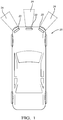
- Figure 1 schematically illustrates an example vehicle 20 including a plurality of detector devices 22 that have associated fields of vision 24.
- the detector devices 22 are capable of detecting RADAR radiation while in other examples, the detector devices 22 are capable of detecting LIDAR radiation.
- FIG. 2 schematically illustrates an example detector device configuration.
- a two-dimensional array 30 of detectors includes a plurality of first detectors 32 aligned with each other in a first direction (e.g., horizontal according to the drawing).
- the array 30 includes a plurality of second detectors 34 aligned with each other in the first direction.
- the second detectors 34 are offset relative to the first detectors 32 in a second direction (e.g., vertically according to the drawing).
- the first and second directions are perpendicular in the illustrated example.
- each of the detectors 32 and each of the detectors 34 comprise an antenna.
- the illustrated example includes a processor 40 that is configured or programmed to determine an angle of detection of the device 22 in a manner that accommodates or compensates for the offset between the first detectors 32 and the second detectors 34.
- the angle of detection in this example embodiment includes a first angle in a first dimension and a second angle in a second dimension that is transverse to the first dimension.
- the first angle is an azimuth angle in a horizontal dimension and the second angle is an elevation angle in a vertical dimension
- the second detector 34 labeled X4 is situated between the first detectors 32 labeled X3 and X5.
- the processor 40 is configured to determine an interpolation coefficient that is related to the offset between the first detectors 32 and the second detectors 34 and compensates for the shifted position of the second detector 34 labeled X4, for example, between the first detectors 32 labeled X3 and X5.
- the shifted array structure provides better measurement in at least one dimension (e.g., horizontal) with a longer array size.
- the illustrated example allows for determining an angle of detection in a second dimension (e.g., vertical) by correcting for the error otherwise introduced by the offset relationship between the detectors.
- Figure 3 is a flowchart diagram 50 that summarizes an example approach of determining an angle of detection with a shifted array structure such as that included in the example detector device 22 schematically shown in Figure 2 .
- a linear relationship is configured that assumes the first detectors 32 are aligned with the second detectors 34.
- a relationship is determined between an interpolation error, which is introduced by the offset between the second detectors 34 and the first detectors 32, and a phase difference associated with that offset.
- a value of the phase difference that minimizes the interpolation error is determined and that phase difference is used for determining the interpolation coefficients from the linear relationship at 58.
- the angle of detection is determined based on the interpolation coefficients, which relate the first detectors 32 and second detectors 34 as if they were in an aligned array structure rather than a shifted array structure.
- the interpolation coefficients are used to compensate for the offset between the first detectors 32 and the second detectors 34.
- a particular implementation of the procedure summarized in Figure 3 includes configuring or developing a linear model that compensates for the offsets between the first detectors 32 and the second detectors 34 and effectively collapses the array to a uniform, linear array.
- Equation 1 above is true if there are less than two targets because only two coefficients are used in that linear relationship or model. Equation 1 is true based on the assumption that there is only one phase shift between the two transmits, which is good for a single target or two targets at the same elevation relative to the sensor device 22.
- ⁇ 2 b ⁇ ⁇ Ac H b ⁇ ⁇ Ac
- b ⁇ ⁇ Ac I ⁇ A A H A ⁇ 1
- Equation 7 is solved for each root and the root that provides the smallest error and smallest angle is selected as the phase angle ⁇ . That selected phase angle may then be used to solve for the interpolation coefficients. The angle of detection of the detector device 22 can then be determined based on those interpolation coefficients.
- the angle of detection in such an embodiment includes an azimuth angle determination and an elevation angle determination.
- the shifted array configuration allows for determining elevation while maintaining azimuth accuracy because it is not necessary to dedicate a channel or channels of a linear array to the elevation measurement, which would effectively shorten the array useable for the azimuth measurement.
- FIG. 4 Another example sensor device configuration is shown in Figure 4 .
- This example includes different spacings between the detectors and some shifted detectors in the array 30'.
- ⁇ ang(z)
- Each of the four roots are used in Equation 11 and the one that minimizes the error and provides the smallest angle is chosen as the value of ⁇ to solve for the interpolation coefficients.
- the smallest angle is useful in embodiments where the elevation field of vision is relatively small.
Landscapes
- Engineering & Computer Science (AREA)
- Radar, Positioning & Navigation (AREA)
- Remote Sensing (AREA)
- Physics & Mathematics (AREA)
- General Physics & Mathematics (AREA)
- Computer Networks & Wireless Communication (AREA)
- Computer Security & Cryptography (AREA)
- Electromagnetism (AREA)
- Radar Systems Or Details Thereof (AREA)
Abstract
Description
- Innovations in electronics and technology have made it possible to incorporate a variety of advanced features on automotive vehicles. Various sensing technologies have been developed for detecting objects or monitoring the surroundings in a vicinity or pathway of a vehicle. Such systems are useful for parking assist, lane departure detection and cruise control adjustment features, for example.
- More recently, automated vehicle features have become possible to allow for autonomous or semi-autonomous vehicle control. Sensors for such systems may incorporate LIDAR (light detection and ranging) or radar for detecting an object or another vehicle in the pathway of or otherwise near the vehicle. Depending on the approach speed, the cruise control setting may be automatically adjusted to reduce the speed of the vehicle based on detecting another vehicle in the pathway of the vehicle, for example.
- One aspect of such sensing technologies includes determining an angle associated with the detection for properly identifying the position of an object external to the vehicle. With known RADAR systems, angle resolution depends on the spacing between the detector elements and the overall antenna or receiver aperture. Automotive sensing devices typically have a small number of transmit and receive channels. These considerations have made the placement of RADAR or LIDAR detector elements critical to achieve a desired level of performance.
- There are challenges associated with designing and utilizing such devices on automotive vehicles. While a larger aperture size can yield better angular discrimination, it does not come without a cost. Increasing the aperture size tends to introduce grating lobes in the spectrum especially when the array spacing is greater than one-half a wavelength as demonstrated by the Nyqist-Shannon sampling theorem. Typical radar detector design includes placing the detector elements in an array with a one-half wavelength spacing between them to avoid grating lobes.
- Those skilled in the art are striving to improve various aspects of detectors useful on vehicles.
- An illustrative example embodiment of a detector device includes a multiple-dimensional array of detectors including a plurality of first detectors aligned with each other in a first direction and a plurality of second detectors aligned with each other in the first direction. The second detectors are offset relative to the first detectors in a second direction that is different than the first direction. A processor determines an interpolation coefficient related to the offset between the first and second detectors and determines an angle of detection of the device based on the interpolation coefficient.
- In an example embodiment having one or more features of the detector device of the previous paragraph, the angle of detection comprises a first angle in a first dimension and a second angle in a second dimension that is transverse with the first dimension.
- In an example embodiment having one or more features of the detector device of either of the previous paragraphs, the first angle is an azimuth and the second angle is an elevation.
- In an example embodiment having one or more features of the detector device of any of the previous paragraphs, the interpolation coefficient comprises a plurality of coefficients and a correction factor.
- In an example embodiment having one or more features of the detector device of any of the previous paragraphs, the plurality of coefficients are coefficients of a linear relationship between the first and second detectors, there is an error in the linear relationship based on the offset between the first and second detectors, and the correction factor reduces an effect of the error.
- In an example embodiment having one or more features of the detector device of any of the previous paragraphs, the offset has an associated phase difference, the error is based the phase difference, and the correction factor corresponds to a value of the phase difference that minimizes the error.
- In an example embodiment having one or more features of the detector device of any of the previous paragraphs, the processor determines at least one value of the phase difference, determines when the at least one value minimizes the error and determines the plurality of coefficients from the linear relationship including the at least one value that minimizes the error.
- In an example embodiment having one or more features of the detector device of any of the previous paragraphs, the first direction is perpendicular to the second direction.
- In an example embodiment having one or more features of the detector device of any of the previous paragraphs, the detectors each comprise an antenna.
- In an example embodiment having one or more features of the detector device of any of the previous paragraphs, the detectors detect at least one of RADAR or LIDAR radiation.
- An illustrative example method of detecting includes determining an interpolation coefficient related to an offset between first and second detectors. The first and second detectors are in a multiple-dimensional array including the first detectors aligned with each other in a first direction and the second detectors aligned with each other in the first direction. The offset is between the first detectors and the second detectors in a second direction that is different than the first direction. The method includes determining an angle of detection of the device using the determined interpolation coefficient.
- In an example embodiment having one or more features of the method of the previous paragraph, determining the angle of detection includes determining a first angle in a first dimension and determining a second angle in a second dimension that is transverse with the first dimension.
- In an example embodiment having one or more features of the method of either of the previous paragraphs, the first angle is an azimuth and the second angle is an elevation.
- In an example embodiment having one or more features of the method of any of the previous paragraphs, determining the interpolation coefficient comprises determining a plurality of coefficients and a correction factor.
- In an example embodiment having one or more features of the method of any of the previous paragraphs, the plurality of coefficients are coefficients of a linear relationship between the first and second detectors, there is an error in the linear relationship based on the offset between the first and second detectors, and the correction factor reduces an effect of the error.
- In an example embodiment having one or more features of the method of any of the previous paragraphs, the offset has an associated phase difference, the error is based the phase difference, and the correction factor corresponds to a value of the phase difference that minimizes the error.
- An example embodiment having one or more features of the method of any of the previous paragraphs includes determining at least one value of the phase difference, determining when the at least one value minimizes the error, and determining the plurality of coefficients from the linear relationship including the at least one value that minimizes the error.
- In an example embodiment having one or more features of the method of any of the previous paragraphs, the first direction is perpendicular to the second direction.
- In an example embodiment having one or more features of the method of any of the previous paragraphs, the detectors each comprise an antenna.
- In an example embodiment having one or more features of the method of any of the previous paragraphs, the detectors detect at least one of RADAR or LIDAR radiation.
- Various features and advantages of at least one disclosed embodiment will become apparent to those skilled in the art from the following detailed description. The drawings that accompany the detailed description can be briefly described as follows.
-
-
Figure 1 schematically illustrates a vehicle including detector devices designed according to an embodiment of this invention. -
Figure 2 schematically illustrates selected components of an example detector device designed according to an embodiment of this invention. -
Figure 3 is a flowchart diagram summarizing an example approach of determining an angle of detection according to an embodiment of this invention. -
Figure 4 schematically illustrates selected components of another example detector device designed according to an embodiment of this invention. - Embodiments of this invention include detector devices that provide an ability to measure angles of detection in two dimensions or two directions. Such devices are useful for a variety of vehicle applications, such as detectors on automated vehicles or semi-autonomous vehicles. Such detectors are also useful for assisting drivers of automotive vehicles.
-
Figure 1 schematically illustrates anexample vehicle 20 including a plurality ofdetector devices 22 that have associated fields ofvision 24. In some examples, thedetector devices 22 are capable of detecting RADAR radiation while in other examples, thedetector devices 22 are capable of detecting LIDAR radiation. -
Figure 2 schematically illustrates an example detector device configuration. A two-dimensional array 30 of detectors includes a plurality offirst detectors 32 aligned with each other in a first direction (e.g., horizontal according to the drawing). Thearray 30 includes a plurality ofsecond detectors 34 aligned with each other in the first direction. As can be appreciated from the illustration, thesecond detectors 34 are offset relative to thefirst detectors 32 in a second direction (e.g., vertically according to the drawing). The first and second directions are perpendicular in the illustrated example. In an example embodiment, each of thedetectors 32 and each of thedetectors 34 comprise an antenna. - Given that there is an offset between the
first detectors 32 and thesecond detectors 34 in the second direction, a typical two-dimensional array approach will not provide accurate results when determining an angle of detection of thedevice 22. The illustrated example includes aprocessor 40 that is configured or programmed to determine an angle of detection of thedevice 22 in a manner that accommodates or compensates for the offset between thefirst detectors 32 and thesecond detectors 34. - The angle of detection in this example embodiment includes a first angle in a first dimension and a second angle in a second dimension that is transverse to the first dimension. For example, the first angle is an azimuth angle in a horizontal dimension and the second angle is an elevation angle in a vertical dimension
- As can be appreciated from
Figure 2 , thesecond detector 34 labeled X4 is situated between thefirst detectors 32 labeled X3 and X5. Theprocessor 40 is configured to determine an interpolation coefficient that is related to the offset between thefirst detectors 32 and thesecond detectors 34 and compensates for the shifted position of thesecond detector 34 labeled X4, for example, between thefirst detectors 32 labeled X3 and X5. - The shifted array structure provides better measurement in at least one dimension (e.g., horizontal) with a longer array size. At the same time, the illustrated example allows for determining an angle of detection in a second dimension (e.g., vertical) by correcting for the error otherwise introduced by the offset relationship between the detectors.
-
Figure 3 is a flowchart diagram 50 that summarizes an example approach of determining an angle of detection with a shifted array structure such as that included in theexample detector device 22 schematically shown inFigure 2 . At 52, a linear relationship is configured that assumes thefirst detectors 32 are aligned with thesecond detectors 34. At 54, a relationship is determined between an interpolation error, which is introduced by the offset between thesecond detectors 34 and thefirst detectors 32, and a phase difference associated with that offset. At 56, a value of the phase difference that minimizes the interpolation error is determined and that phase difference is used for determining the interpolation coefficients from the linear relationship at 58. At 60, the angle of detection is determined based on the interpolation coefficients, which relate thefirst detectors 32 andsecond detectors 34 as if they were in an aligned array structure rather than a shifted array structure. In other words, the interpolation coefficients are used to compensate for the offset between thefirst detectors 32 and thesecond detectors 34. - A particular implementation of the procedure summarized in
Figure 3 includes configuring or developing a linear model that compensates for the offsets between thefirst detectors 32 and thesecond detectors 34 and effectively collapses the array to a uniform, linear array. A linear relationship may be expressed using the following equation:

first detectors 32 and thesecond detectors 34. - Equation 1 above is true if there are less than two targets because only two coefficients are used in that linear relationship or model. Equation 1 is true based on the assumption that there is only one phase shift between the two transmits, which is good for a single target or two targets at the same elevation relative to the
sensor device 22. - Equation 1 can be expanded to include all of the interpolation pairs in the array and the forward-backward array, which would make the solution more robust to noise. Expanding equation 1 in this manner yields


- A least squares solution of the interpolation coefficients c is given by the pseudo-inverse as follows

- From that equation, the interpolation error expressed in terms of θ can be represented by the following equation


- Considering P and P□ as projectors (P=PH and P·P=P), then Equation 5 can be further written as

- The projector P□ may be partitioned as

- Then Equation 6 can be written as

- Taking the partial derivative of the interpolation error with respect to θ and setting it to 0 yields


- It follows that ejθ is the quadratic root of γ/β and


- There are four roots (i.e., quadratic) for the solution represented by Equation 9. According to one example embodiment, Equation 7 is solved for each root and the root that provides the smallest error and smallest angle is selected as the phase angle θ. That selected phase angle may then be used to solve for the interpolation coefficients. The angle of detection of the
detector device 22 can then be determined based on those interpolation coefficients. - The angle of detection in such an embodiment includes an azimuth angle determination and an elevation angle determination. The shifted array configuration allows for determining elevation while maintaining azimuth accuracy because it is not necessary to dedicate a channel or channels of a linear array to the elevation measurement, which would effectively shorten the array useable for the azimuth measurement.
- Setting a correspondence between the error associated with the interpolation between the detectors and the phase difference between the levels in the elevation dimension allows for simultaneously determining the azimuth and elevation angles using the shifted array configuration. The linear interpolation between the detectors in the array assumes no shift is present. Estimating the elevation measurement includes correcting the error by assuming a model where a shift in elevation is present. A linear model as described above interpolates between adjacent ones of the
first detectors 32, for example, at the same time as correcting the shift of thesecond detector 34 between thosefirst detectors 32. - Another example sensor device configuration is shown in
Figure 4 . This example includes different spacings between the detectors and some shifted detectors in the array 30'. For such an array configuration, Equation 3 above can be rewritten as:
- The projector P□ may be partitioned as:


- After taking the partial derivative of the error with respect to θ and setting it to zero, the following is true

- Letting z = ejθ in Equation 12 yields

- Similar to the previous example, quadratic roots can be obtained by solving Equation 13 and θ = ang(z). Each of the four roots are used in Equation 11 and the one that minimizes the error and provides the smallest angle is chosen as the value of θ to solve for the interpolation coefficients. The smallest angle is useful in embodiments where the elevation field of vision is relatively small.
- While each of the example embodiments discussed above have features that are attributed to the particular embodiment being discussed, those features are not limited to only that embodiment. Other embodiments are possible that include combinations of selected ones of the features of the disclosed embodiments.
- The preceding description is exemplary rather than limiting in nature. Variations and modifications to the disclosed examples may become apparent to those skilled in the art that do not necessarily depart from the essence of this invention. The scope of legal protection given to this invention can only be determined by studying the following claims.
Claims (14)
- A detector device (22), comprising:a multiple-dimensional array (30) of detectors including a plurality of first detectors (32) aligned with each other in a first direction and a plurality of second detectors (34) aligned with each other in the first direction, the second detectors (34) being offset relative to the first detectors (32) in a second direction that is different than the first direction; anda processor (40) that determines an interpolation coefficient related to the offset between the first detectors (32) and the second detectors (34) and determines an angle of detection of the device (22) based on the interpolation coefficient.
- The detector device (22) of claim 1, wherein the angle of detection comprises a first angle in a first dimension and a second angle in a second dimension that is transverse with the first dimension.
- The detector device (22) of claim 2, wherein the first angle is an azimuth and the second angle is an elevation.
- The detector device (22) according to any one of the preceding claims, wherein the interpolation coefficient comprises a plurality of coefficients and a correction factor.
- The detector device (22) according to any one of the preceding claims, wherein the first direction is perpendicular to the second direction.
- The detector device (22) according to any one of the preceding claims, wherein the detectors each comprise an antenna.
- The detector device (22) according to any one of the preceding claims, wherein the detectors detect at least one of RADAR or LIDAR radiation.
- A method of detecting, comprising:determining an interpolation coefficient related to an offset between a first detector (32) and a second detector (34), wherein the first detector (32) and the second detector (34) are in a multiple-dimensional array (30) including the first detectors (32) aligned with each other in a first direction and the second detectors (34) aligned with each other in the first direction, and wherein the offset is between the first detectors (32) and the second detectors (34) in a second direction that is different than the first direction; anddetermining an angle of detection of the device (22) using the determined interpolation coefficient.
- The method of claim 8, wherein determining the angle of detection comprises
determining a first angle in a first dimension; and
determining a second angle in a second dimension that is transverse with the first dimension. - The method according of claim 9, wherein the first angle is an azimuth and the second angle is an elevation.
- The method according to any one of the claims 8 to 10, wherein determining the interpolation coefficient comprises determining a plurality of coefficients and a correction factor.
- The method according to any one of the claims 8 to 11, wherein the first direction is perpendicular to the second direction.
- The method according to any one of the claims 8 to 12, wherein the detectors each comprise an antenna.
- The method according to any one of the claims 8 to 13, wherein the detectors detect at least one of RADAR or LIDAR radiation.
Applications Claiming Priority (2)
| Application Number | Priority Date | Filing Date | Title |
|---|---|---|---|
| US201762470942P | 2017-03-14 | 2017-03-14 | |
| US15/706,882 US10725152B2 (en) | 2017-03-14 | 2017-09-18 | Detector device including a shifted multi-dimensional array of detector elements |
Publications (2)
| Publication Number | Publication Date |
|---|---|
| EP3376252A1 true EP3376252A1 (en) | 2018-09-19 |
| EP3376252B1 EP3376252B1 (en) | 2023-10-11 |
Family
ID=61521386
Family Applications (1)
| Application Number | Title | Priority Date | Filing Date |
|---|---|---|---|
| EP18159002.7A Active EP3376252B1 (en) | 2017-03-14 | 2018-02-27 | Detector device including a shifted multi-dimensional array of detector elements |
Country Status (3)
| Country | Link |
|---|---|
| US (1) | US10725152B2 (en) |
| EP (1) | EP3376252B1 (en) |
| CN (2) | CN108571946B (en) |
Families Citing this family (6)
| Publication number | Priority date | Publication date | Assignee | Title |
|---|---|---|---|---|
| AU2017315762B2 (en) | 2016-08-24 | 2020-04-09 | Ouster, Inc. | Optical system for collecting distance information within a field |
| US11444377B2 (en) | 2019-10-03 | 2022-09-13 | Aptiv Technologies Limited | Radiation pattern reconfigurable antenna |
| CN111016859B (en) * | 2019-12-20 | 2021-12-10 | 南京泰晟科技实业有限公司 | Vehicle emergency brake protection system and method |
| CN110824469B (en) * | 2020-01-09 | 2020-05-05 | 南京泰晟科技实业有限公司 | Lane deviation detection device and deviation correction judgment method |
| CN116466342A (en) * | 2022-01-19 | 2023-07-21 | 安波福技术有限公司 | Radar System with Sequential 2D Angle Estimation |
| US12345797B2 (en) | 2022-11-19 | 2025-07-01 | Nxp B.V. | Super-resolution MIMO sparse array automotive radar based on forward and backward hankel matrix completion |
Citations (3)
| Publication number | Priority date | Publication date | Assignee | Title |
|---|---|---|---|---|
| WO2013053467A1 (en) * | 2011-10-15 | 2013-04-18 | Volkswagen Aktiengesellschaft | Radar system for a road vehicle with improved calibrating possibilities |
| US20160104946A1 (en) * | 2013-05-08 | 2016-04-14 | Denso Corporation | Radar apparatus |
| US20170187102A1 (en) * | 2015-12-24 | 2017-06-29 | Nidec Elesys Corporation | On-vehicle radar device |
Family Cites Families (7)
| Publication number | Priority date | Publication date | Assignee | Title |
|---|---|---|---|---|
| AUPP839199A0 (en) * | 1999-02-01 | 1999-02-25 | Traffic Pro Pty Ltd | Object recognition & tracking system |
| FR2826762B1 (en) * | 2001-06-29 | 2004-02-06 | Thales Sa | METHOD FOR SYNTHESIZING AN INTERVISIBILITY IMAGE |
| JP4698087B2 (en) * | 2001-08-15 | 2011-06-08 | 富士通テン株式会社 | Radar horizontal axis deviation occurrence detection apparatus, axis deviation determination apparatus, and axis deviation correction apparatus |
| BRPI0622161A2 (en) | 2006-12-11 | 2011-12-27 | Ericsson Telefon Ab L M | radar system, and method for providing an image of a |
| KR101112607B1 (en) * | 2009-10-12 | 2012-02-15 | 주식회사 한터기술 | Vehicle Position Detection System Using Array Magnetic Sensor |
| JP5093298B2 (en) | 2010-06-04 | 2012-12-12 | 株式会社デンソー | Direction detection device |
| JP2013224893A (en) | 2012-04-23 | 2013-10-31 | Honda Elesys Co Ltd | Direction detection device, direction detection method, and direction detection program |
-
2017
- 2017-09-18 US US15/706,882 patent/US10725152B2/en active Active
-
2018
- 2018-02-27 EP EP18159002.7A patent/EP3376252B1/en active Active
- 2018-03-13 CN CN201810205314.3A patent/CN108571946B/en active Active
- 2018-03-13 CN CN202110164116.9A patent/CN112945181B/en active Active
Patent Citations (3)
| Publication number | Priority date | Publication date | Assignee | Title |
|---|---|---|---|---|
| WO2013053467A1 (en) * | 2011-10-15 | 2013-04-18 | Volkswagen Aktiengesellschaft | Radar system for a road vehicle with improved calibrating possibilities |
| US20160104946A1 (en) * | 2013-05-08 | 2016-04-14 | Denso Corporation | Radar apparatus |
| US20170187102A1 (en) * | 2015-12-24 | 2017-06-29 | Nidec Elesys Corporation | On-vehicle radar device |
Also Published As
| Publication number | Publication date |
|---|---|
| CN112945181A (en) | 2021-06-11 |
| CN112945181B (en) | 2023-03-28 |
| US10725152B2 (en) | 2020-07-28 |
| US20180267143A1 (en) | 2018-09-20 |
| CN108571946A (en) | 2018-09-25 |
| CN108571946B (en) | 2021-02-02 |
| EP3376252B1 (en) | 2023-10-11 |
Similar Documents
| Publication | Publication Date | Title |
|---|---|---|
| US10725152B2 (en) | Detector device including a shifted multi-dimensional array of detector elements | |
| RU2662411C2 (en) | Method of camera calibration | |
| RU2727164C1 (en) | Method and apparatus for correcting map data | |
| US9148657B2 (en) | Calibration device, range-finding system including the calibration device and stereo camera, and vehicle mounting the range-finding system | |
| US9097541B2 (en) | Driving support device | |
| US9672624B2 (en) | Method for calibrating absolute misalignment between linear array image sensor and attitude control sensor | |
| US20140347206A1 (en) | Method and device for ascertaining a misalignment of a radar sensor of a vehicle | |
| US20100235129A1 (en) | Calibration of multi-sensor system | |
| CN112710339B (en) | Method and apparatus for calibrating vehicle sensors | |
| EP0989414A3 (en) | Method and apparatus for calibrating azimuth boresight in a radar system | |
| EP2990765A1 (en) | Image processing device, image processing method, and program therefor | |
| US20140085409A1 (en) | Wide fov camera image calibration and de-warping | |
| US20210364614A1 (en) | Radar apparatus and method for operating a radar apparatus | |
| EP4109405B1 (en) | Method and apparatus with sensor calibration | |
| JP2015525873A (en) | Misalignment processing of radar sensors for vehicles | |
| US20120313820A1 (en) | System technique for conical geo-location of radio frequency sources | |
| US11454698B2 (en) | Radar mount-angle calibration | |
| KR20130113102A (en) | Calibration method and device for horizontal alignment of vehicle radar | |
| KR101932041B1 (en) | Method and apparatus for calibration of dual Lidar sensors | |
| KR20240087982A (en) | Method and apparatus for radar signal processing | |
| US20240142598A1 (en) | Method and device for aligning radar of vehicle | |
| JP7526858B2 (en) | Measurement device, measurement method, and program | |
| CN114019539A (en) | Multi-sensor relay calibration method | |
| CN115792827A (en) | Vehicle-mounted radar pitch angle error calibration and correction method, device, medium and equipment | |
| US12591038B2 (en) | Radar control device and method |
Legal Events
| Date | Code | Title | Description |
|---|---|---|---|
| PUAI | Public reference made under article 153(3) epc to a published international application that has entered the european phase |
Free format text: ORIGINAL CODE: 0009012 |
|
| STAA | Information on the status of an ep patent application or granted ep patent |
Free format text: STATUS: THE APPLICATION HAS BEEN PUBLISHED |
|
| AK | Designated contracting states |
Kind code of ref document: A1 Designated state(s): AL AT BE BG CH CY CZ DE DK EE ES FI FR GB GR HR HU IE IS IT LI LT LU LV MC MK MT NL NO PL PT RO RS SE SI SK SM TR |
|
| AX | Request for extension of the european patent |
Extension state: BA ME |
|
| RAP1 | Party data changed (applicant data changed or rights of an application transferred) |
Owner name: APTIV TECHNOLOGIES LIMITED |
|
| STAA | Information on the status of an ep patent application or granted ep patent |
Free format text: STATUS: REQUEST FOR EXAMINATION WAS MADE |
|
| 17P | Request for examination filed |
Effective date: 20190319 |
|
| RBV | Designated contracting states (corrected) |
Designated state(s): AL AT BE BG CH CY CZ DE DK EE ES FI FR GB GR HR HU IE IS IT LI LT LU LV MC MK MT NL NO PL PT RO RS SE SI SK SM TR |
|
| STAA | Information on the status of an ep patent application or granted ep patent |
Free format text: STATUS: EXAMINATION IS IN PROGRESS |
|
| 17Q | First examination report despatched |
Effective date: 20210120 |
|
| RAP3 | Party data changed (applicant data changed or rights of an application transferred) |
Owner name: APTIV TECHNOLOGIES LIMITED |
|
| GRAP | Despatch of communication of intention to grant a patent |
Free format text: ORIGINAL CODE: EPIDOSNIGR1 |
|
| STAA | Information on the status of an ep patent application or granted ep patent |
Free format text: STATUS: GRANT OF PATENT IS INTENDED |
|
| RIC1 | Information provided on ipc code assigned before grant |
Ipc: H01Q 1/32 20060101ALI20230417BHEP Ipc: G01S 13/42 20060101ALI20230417BHEP Ipc: G01S 13/87 20060101ALI20230417BHEP Ipc: G01S 13/931 20200101ALI20230417BHEP Ipc: H01Q 21/08 20060101ALI20230417BHEP Ipc: H01Q 21/22 20060101ALI20230417BHEP Ipc: H01Q 25/00 20060101ALI20230417BHEP Ipc: G01S 7/03 20060101AFI20230417BHEP |
|
| INTG | Intention to grant announced |
Effective date: 20230523 |
|
| GRAS | Grant fee paid |
Free format text: ORIGINAL CODE: EPIDOSNIGR3 |
|
| GRAA | (expected) grant |
Free format text: ORIGINAL CODE: 0009210 |
|
| STAA | Information on the status of an ep patent application or granted ep patent |
Free format text: STATUS: THE PATENT HAS BEEN GRANTED |
|
| AK | Designated contracting states |
Kind code of ref document: B1 Designated state(s): AL AT BE BG CH CY CZ DE DK EE ES FI FR GB GR HR HU IE IS IT LI LT LU LV MC MK MT NL NO PL PT RO RS SE SI SK SM TR |
|
| REG | Reference to a national code |
Ref country code: GB Ref legal event code: FG4D |
|
| REG | Reference to a national code |
Ref country code: CH Ref legal event code: EP |
|
| REG | Reference to a national code |
Ref country code: DE Ref legal event code: R096 Ref document number: 602018059045 Country of ref document: DE |
|
| REG | Reference to a national code |
Ref country code: IE Ref legal event code: FG4D |
|
| P01 | Opt-out of the competence of the unified patent court (upc) registered |
Effective date: 20231109 |
|
| REG | Reference to a national code |
Ref country code: LT Ref legal event code: MG9D |
|
| REG | Reference to a national code |
Ref country code: NL Ref legal event code: MP Effective date: 20231011 |
|
| REG | Reference to a national code |
Ref country code: AT Ref legal event code: MK05 Ref document number: 1620741 Country of ref document: AT Kind code of ref document: T Effective date: 20231011 |
|
| PG25 | Lapsed in a contracting state [announced via postgrant information from national office to epo] |
Ref country code: NL Free format text: LAPSE BECAUSE OF FAILURE TO SUBMIT A TRANSLATION OF THE DESCRIPTION OR TO PAY THE FEE WITHIN THE PRESCRIBED TIME-LIMIT Effective date: 20231011 |
|
| PG25 | Lapsed in a contracting state [announced via postgrant information from national office to epo] |
Ref country code: GR Free format text: LAPSE BECAUSE OF FAILURE TO SUBMIT A TRANSLATION OF THE DESCRIPTION OR TO PAY THE FEE WITHIN THE PRESCRIBED TIME-LIMIT Effective date: 20240112 |
|
| PG25 | Lapsed in a contracting state [announced via postgrant information from national office to epo] |
Ref country code: IS Free format text: LAPSE BECAUSE OF FAILURE TO SUBMIT A TRANSLATION OF THE DESCRIPTION OR TO PAY THE FEE WITHIN THE PRESCRIBED TIME-LIMIT Effective date: 20240211 |
|
| PG25 | Lapsed in a contracting state [announced via postgrant information from national office to epo] |
Ref country code: LT Free format text: LAPSE BECAUSE OF FAILURE TO SUBMIT A TRANSLATION OF THE DESCRIPTION OR TO PAY THE FEE WITHIN THE PRESCRIBED TIME-LIMIT Effective date: 20231011 |
|
| PG25 | Lapsed in a contracting state [announced via postgrant information from national office to epo] |
Ref country code: AT Free format text: LAPSE BECAUSE OF FAILURE TO SUBMIT A TRANSLATION OF THE DESCRIPTION OR TO PAY THE FEE WITHIN THE PRESCRIBED TIME-LIMIT Effective date: 20231011 |
|
| PG25 | Lapsed in a contracting state [announced via postgrant information from national office to epo] |
Ref country code: ES Free format text: LAPSE BECAUSE OF FAILURE TO SUBMIT A TRANSLATION OF THE DESCRIPTION OR TO PAY THE FEE WITHIN THE PRESCRIBED TIME-LIMIT Effective date: 20231011 |
|
| PG25 | Lapsed in a contracting state [announced via postgrant information from national office to epo] |
Ref country code: LT Free format text: LAPSE BECAUSE OF FAILURE TO SUBMIT A TRANSLATION OF THE DESCRIPTION OR TO PAY THE FEE WITHIN THE PRESCRIBED TIME-LIMIT Effective date: 20231011 Ref country code: IS Free format text: LAPSE BECAUSE OF FAILURE TO SUBMIT A TRANSLATION OF THE DESCRIPTION OR TO PAY THE FEE WITHIN THE PRESCRIBED TIME-LIMIT Effective date: 20240211 Ref country code: GR Free format text: LAPSE BECAUSE OF FAILURE TO SUBMIT A TRANSLATION OF THE DESCRIPTION OR TO PAY THE FEE WITHIN THE PRESCRIBED TIME-LIMIT Effective date: 20240112 Ref country code: ES Free format text: LAPSE BECAUSE OF FAILURE TO SUBMIT A TRANSLATION OF THE DESCRIPTION OR TO PAY THE FEE WITHIN THE PRESCRIBED TIME-LIMIT Effective date: 20231011 Ref country code: BG Free format text: LAPSE BECAUSE OF FAILURE TO SUBMIT A TRANSLATION OF THE DESCRIPTION OR TO PAY THE FEE WITHIN THE PRESCRIBED TIME-LIMIT Effective date: 20240111 Ref country code: AT Free format text: LAPSE BECAUSE OF FAILURE TO SUBMIT A TRANSLATION OF THE DESCRIPTION OR TO PAY THE FEE WITHIN THE PRESCRIBED TIME-LIMIT Effective date: 20231011 Ref country code: PT Free format text: LAPSE BECAUSE OF FAILURE TO SUBMIT A TRANSLATION OF THE DESCRIPTION OR TO PAY THE FEE WITHIN THE PRESCRIBED TIME-LIMIT Effective date: 20240212 |
|
| PG25 | Lapsed in a contracting state [announced via postgrant information from national office to epo] |
Ref country code: SE Free format text: LAPSE BECAUSE OF FAILURE TO SUBMIT A TRANSLATION OF THE DESCRIPTION OR TO PAY THE FEE WITHIN THE PRESCRIBED TIME-LIMIT Effective date: 20231011 Ref country code: RS Free format text: LAPSE BECAUSE OF FAILURE TO SUBMIT A TRANSLATION OF THE DESCRIPTION OR TO PAY THE FEE WITHIN THE PRESCRIBED TIME-LIMIT Effective date: 20231011 Ref country code: PL Free format text: LAPSE BECAUSE OF FAILURE TO SUBMIT A TRANSLATION OF THE DESCRIPTION OR TO PAY THE FEE WITHIN THE PRESCRIBED TIME-LIMIT Effective date: 20231011 Ref country code: NO Free format text: LAPSE BECAUSE OF FAILURE TO SUBMIT A TRANSLATION OF THE DESCRIPTION OR TO PAY THE FEE WITHIN THE PRESCRIBED TIME-LIMIT Effective date: 20240111 Ref country code: LV Free format text: LAPSE BECAUSE OF FAILURE TO SUBMIT A TRANSLATION OF THE DESCRIPTION OR TO PAY THE FEE WITHIN THE PRESCRIBED TIME-LIMIT Effective date: 20231011 Ref country code: HR Free format text: LAPSE BECAUSE OF FAILURE TO SUBMIT A TRANSLATION OF THE DESCRIPTION OR TO PAY THE FEE WITHIN THE PRESCRIBED TIME-LIMIT Effective date: 20231011 |
|
| PG25 | Lapsed in a contracting state [announced via postgrant information from national office to epo] |
Ref country code: DK Free format text: LAPSE BECAUSE OF FAILURE TO SUBMIT A TRANSLATION OF THE DESCRIPTION OR TO PAY THE FEE WITHIN THE PRESCRIBED TIME-LIMIT Effective date: 20231011 |
|
| REG | Reference to a national code |
Ref country code: DE Ref legal event code: R097 Ref document number: 602018059045 Country of ref document: DE |
|
| PG25 | Lapsed in a contracting state [announced via postgrant information from national office to epo] |
Ref country code: CZ Free format text: LAPSE BECAUSE OF FAILURE TO SUBMIT A TRANSLATION OF THE DESCRIPTION OR TO PAY THE FEE WITHIN THE PRESCRIBED TIME-LIMIT Effective date: 20231011 |
|
| PG25 | Lapsed in a contracting state [announced via postgrant information from national office to epo] |
Ref country code: SK Free format text: LAPSE BECAUSE OF FAILURE TO SUBMIT A TRANSLATION OF THE DESCRIPTION OR TO PAY THE FEE WITHIN THE PRESCRIBED TIME-LIMIT Effective date: 20231011 |
|
| PG25 | Lapsed in a contracting state [announced via postgrant information from national office to epo] |
Ref country code: SM Free format text: LAPSE BECAUSE OF FAILURE TO SUBMIT A TRANSLATION OF THE DESCRIPTION OR TO PAY THE FEE WITHIN THE PRESCRIBED TIME-LIMIT Effective date: 20231011 Ref country code: SK Free format text: LAPSE BECAUSE OF FAILURE TO SUBMIT A TRANSLATION OF THE DESCRIPTION OR TO PAY THE FEE WITHIN THE PRESCRIBED TIME-LIMIT Effective date: 20231011 Ref country code: RO Free format text: LAPSE BECAUSE OF FAILURE TO SUBMIT A TRANSLATION OF THE DESCRIPTION OR TO PAY THE FEE WITHIN THE PRESCRIBED TIME-LIMIT Effective date: 20231011 Ref country code: IT Free format text: LAPSE BECAUSE OF FAILURE TO SUBMIT A TRANSLATION OF THE DESCRIPTION OR TO PAY THE FEE WITHIN THE PRESCRIBED TIME-LIMIT Effective date: 20231011 Ref country code: EE Free format text: LAPSE BECAUSE OF FAILURE TO SUBMIT A TRANSLATION OF THE DESCRIPTION OR TO PAY THE FEE WITHIN THE PRESCRIBED TIME-LIMIT Effective date: 20231011 Ref country code: DK Free format text: LAPSE BECAUSE OF FAILURE TO SUBMIT A TRANSLATION OF THE DESCRIPTION OR TO PAY THE FEE WITHIN THE PRESCRIBED TIME-LIMIT Effective date: 20231011 Ref country code: CZ Free format text: LAPSE BECAUSE OF FAILURE TO SUBMIT A TRANSLATION OF THE DESCRIPTION OR TO PAY THE FEE WITHIN THE PRESCRIBED TIME-LIMIT Effective date: 20231011 |
|
| PLBE | No opposition filed within time limit |
Free format text: ORIGINAL CODE: 0009261 |
|
| STAA | Information on the status of an ep patent application or granted ep patent |
Free format text: STATUS: NO OPPOSITION FILED WITHIN TIME LIMIT |
|
| 26N | No opposition filed |
Effective date: 20240712 |
|
| PG25 | Lapsed in a contracting state [announced via postgrant information from national office to epo] |
Ref country code: MC Free format text: LAPSE BECAUSE OF FAILURE TO SUBMIT A TRANSLATION OF THE DESCRIPTION OR TO PAY THE FEE WITHIN THE PRESCRIBED TIME-LIMIT Effective date: 20231011 |
|
| REG | Reference to a national code |
Ref country code: CH Ref legal event code: PL |
|
| PG25 | Lapsed in a contracting state [announced via postgrant information from national office to epo] |
Ref country code: LU Free format text: LAPSE BECAUSE OF NON-PAYMENT OF DUE FEES Effective date: 20240227 |
|
| PG25 | Lapsed in a contracting state [announced via postgrant information from national office to epo] |
Ref country code: CH Free format text: LAPSE BECAUSE OF NON-PAYMENT OF DUE FEES Effective date: 20240229 |
|
| PG25 | Lapsed in a contracting state [announced via postgrant information from national office to epo] |
Ref country code: SI Free format text: LAPSE BECAUSE OF FAILURE TO SUBMIT A TRANSLATION OF THE DESCRIPTION OR TO PAY THE FEE WITHIN THE PRESCRIBED TIME-LIMIT Effective date: 20231011 |
|
| PG25 | Lapsed in a contracting state [announced via postgrant information from national office to epo] |
Ref country code: SI Free format text: LAPSE BECAUSE OF FAILURE TO SUBMIT A TRANSLATION OF THE DESCRIPTION OR TO PAY THE FEE WITHIN THE PRESCRIBED TIME-LIMIT Effective date: 20231011 Ref country code: LU Free format text: LAPSE BECAUSE OF NON-PAYMENT OF DUE FEES Effective date: 20240227 Ref country code: CH Free format text: LAPSE BECAUSE OF NON-PAYMENT OF DUE FEES Effective date: 20240229 |
|
| REG | Reference to a national code |
Ref country code: BE Ref legal event code: MM Effective date: 20240229 |
|
| PG25 | Lapsed in a contracting state [announced via postgrant information from national office to epo] |
Ref country code: BE Free format text: LAPSE BECAUSE OF NON-PAYMENT OF DUE FEES Effective date: 20240229 |
|
| PG25 | Lapsed in a contracting state [announced via postgrant information from national office to epo] |
Ref country code: IE Free format text: LAPSE BECAUSE OF NON-PAYMENT OF DUE FEES Effective date: 20240227 |
|
| PG25 | Lapsed in a contracting state [announced via postgrant information from national office to epo] |
Ref country code: IE Free format text: LAPSE BECAUSE OF NON-PAYMENT OF DUE FEES Effective date: 20240227 Ref country code: BE Free format text: LAPSE BECAUSE OF NON-PAYMENT OF DUE FEES Effective date: 20240229 |
|
| REG | Reference to a national code |
Ref country code: DE Ref legal event code: R081 Ref document number: 602018059045 Country of ref document: DE Owner name: APTIV TECHNOLOGIES AG, CH Free format text: FORMER OWNER: APTIV TECHNOLOGIES LIMITED, ST. MICHAEL, BB |
|
| PG25 | Lapsed in a contracting state [announced via postgrant information from national office to epo] |
Ref country code: CY Free format text: LAPSE BECAUSE OF FAILURE TO SUBMIT A TRANSLATION OF THE DESCRIPTION OR TO PAY THE FEE WITHIN THE PRESCRIBED TIME-LIMIT; INVALID AB INITIO Effective date: 20180227 |
|
| PG25 | Lapsed in a contracting state [announced via postgrant information from national office to epo] |
Ref country code: HU Free format text: LAPSE BECAUSE OF FAILURE TO SUBMIT A TRANSLATION OF THE DESCRIPTION OR TO PAY THE FEE WITHIN THE PRESCRIBED TIME-LIMIT; INVALID AB INITIO Effective date: 20180227 |
|
| PG25 | Lapsed in a contracting state [announced via postgrant information from national office to epo] |
Ref country code: FI Free format text: LAPSE BECAUSE OF FAILURE TO SUBMIT A TRANSLATION OF THE DESCRIPTION OR TO PAY THE FEE WITHIN THE PRESCRIBED TIME-LIMIT Effective date: 20231011 |
|
| PG25 | Lapsed in a contracting state [announced via postgrant information from national office to epo] |
Ref country code: TR Free format text: LAPSE BECAUSE OF FAILURE TO SUBMIT A TRANSLATION OF THE DESCRIPTION OR TO PAY THE FEE WITHIN THE PRESCRIBED TIME-LIMIT Effective date: 20231011 |
|
| PGFP | Annual fee paid to national office [announced via postgrant information from national office to epo] |
Ref country code: GB Payment date: 20260204 Year of fee payment: 9 |
|
| PGFP | Annual fee paid to national office [announced via postgrant information from national office to epo] |
Ref country code: DE Payment date: 20260121 Year of fee payment: 9 |
|
| PGFP | Annual fee paid to national office [announced via postgrant information from national office to epo] |
Ref country code: FR Payment date: 20260205 Year of fee payment: 9 |