EP3376099A1 - Led lighting arrangement - Google Patents
Led lighting arrangement Download PDFInfo
- Publication number
- EP3376099A1 EP3376099A1 EP17161501.6A EP17161501A EP3376099A1 EP 3376099 A1 EP3376099 A1 EP 3376099A1 EP 17161501 A EP17161501 A EP 17161501A EP 3376099 A1 EP3376099 A1 EP 3376099A1
- Authority
- EP
- European Patent Office
- Prior art keywords
- holder
- optical
- sub
- main part
- lighting arrangement
- Prior art date
- Legal status (The legal status is an assumption and is not a legal conclusion. Google has not performed a legal analysis and makes no representation as to the accuracy of the status listed.)
- Granted
Links
Images




Classifications
-
- F—MECHANICAL ENGINEERING; LIGHTING; HEATING; WEAPONS; BLASTING
- F21—LIGHTING
- F21V—FUNCTIONAL FEATURES OR DETAILS OF LIGHTING DEVICES OR SYSTEMS THEREOF; STRUCTURAL COMBINATIONS OF LIGHTING DEVICES WITH OTHER ARTICLES, NOT OTHERWISE PROVIDED FOR
- F21V17/00—Fastening of component parts of lighting devices, e.g. shades, globes, refractors, reflectors, filters, screens, grids or protective cages
- F21V17/06—Fastening of component parts of lighting devices, e.g. shades, globes, refractors, reflectors, filters, screens, grids or protective cages the fastening being onto or by the lampholder
-
- F—MECHANICAL ENGINEERING; LIGHTING; HEATING; WEAPONS; BLASTING
- F21—LIGHTING
- F21S—NON-PORTABLE LIGHTING DEVICES; SYSTEMS THEREOF; VEHICLE LIGHTING DEVICES SPECIALLY ADAPTED FOR VEHICLE EXTERIORS
- F21S2/00—Systems of lighting devices, not provided for in main groups F21S4/00 - F21S10/00 or F21S19/00, e.g. of modular construction
- F21S2/005—Systems of lighting devices, not provided for in main groups F21S4/00 - F21S10/00 or F21S19/00, e.g. of modular construction of modular construction
-
- F—MECHANICAL ENGINEERING; LIGHTING; HEATING; WEAPONS; BLASTING
- F21—LIGHTING
- F21K—NON-ELECTRIC LIGHT SOURCES USING LUMINESCENCE; LIGHT SOURCES USING ELECTROCHEMILUMINESCENCE; LIGHT SOURCES USING CHARGES OF COMBUSTIBLE MATERIAL; LIGHT SOURCES USING SEMICONDUCTOR DEVICES AS LIGHT-GENERATING ELEMENTS; LIGHT SOURCES NOT OTHERWISE PROVIDED FOR
- F21K9/00—Light sources using semiconductor devices as light-generating elements, e.g. using light-emitting diodes [LED] or lasers
- F21K9/20—Light sources comprising attachment means
-
- B—PERFORMING OPERATIONS; TRANSPORTING
- B23—MACHINE TOOLS; METAL-WORKING NOT OTHERWISE PROVIDED FOR
- B23P—METAL-WORKING NOT OTHERWISE PROVIDED FOR; COMBINED OPERATIONS; UNIVERSAL MACHINE TOOLS
- B23P19/00—Machines for simply fitting together or separating metal parts or objects, or metal and non-metal parts, whether or not involving some deformation; Tools or devices therefor so far as not provided for in other classes
- B23P19/04—Machines for simply fitting together or separating metal parts or objects, or metal and non-metal parts, whether or not involving some deformation; Tools or devices therefor so far as not provided for in other classes for assembling or disassembling parts
-
- F—MECHANICAL ENGINEERING; LIGHTING; HEATING; WEAPONS; BLASTING
- F21—LIGHTING
- F21K—NON-ELECTRIC LIGHT SOURCES USING LUMINESCENCE; LIGHT SOURCES USING ELECTROCHEMILUMINESCENCE; LIGHT SOURCES USING CHARGES OF COMBUSTIBLE MATERIAL; LIGHT SOURCES USING SEMICONDUCTOR DEVICES AS LIGHT-GENERATING ELEMENTS; LIGHT SOURCES NOT OTHERWISE PROVIDED FOR
- F21K9/00—Light sources using semiconductor devices as light-generating elements, e.g. using light-emitting diodes [LED] or lasers
- F21K9/60—Optical arrangements integrated in the light source, e.g. for improving the colour rendering index or the light extraction
-
- F—MECHANICAL ENGINEERING; LIGHTING; HEATING; WEAPONS; BLASTING
- F21—LIGHTING
- F21K—NON-ELECTRIC LIGHT SOURCES USING LUMINESCENCE; LIGHT SOURCES USING ELECTROCHEMILUMINESCENCE; LIGHT SOURCES USING CHARGES OF COMBUSTIBLE MATERIAL; LIGHT SOURCES USING SEMICONDUCTOR DEVICES AS LIGHT-GENERATING ELEMENTS; LIGHT SOURCES NOT OTHERWISE PROVIDED FOR
- F21K9/00—Light sources using semiconductor devices as light-generating elements, e.g. using light-emitting diodes [LED] or lasers
- F21K9/90—Methods of manufacture
-
- F—MECHANICAL ENGINEERING; LIGHTING; HEATING; WEAPONS; BLASTING
- F21—LIGHTING
- F21V—FUNCTIONAL FEATURES OR DETAILS OF LIGHTING DEVICES OR SYSTEMS THEREOF; STRUCTURAL COMBINATIONS OF LIGHTING DEVICES WITH OTHER ARTICLES, NOT OTHERWISE PROVIDED FOR
- F21V17/00—Fastening of component parts of lighting devices, e.g. shades, globes, refractors, reflectors, filters, screens, grids or protective cages
- F21V17/10—Fastening of component parts of lighting devices, e.g. shades, globes, refractors, reflectors, filters, screens, grids or protective cages characterised by specific fastening means or way of fastening
-
- F—MECHANICAL ENGINEERING; LIGHTING; HEATING; WEAPONS; BLASTING
- F21—LIGHTING
- F21V—FUNCTIONAL FEATURES OR DETAILS OF LIGHTING DEVICES OR SYSTEMS THEREOF; STRUCTURAL COMBINATIONS OF LIGHTING DEVICES WITH OTHER ARTICLES, NOT OTHERWISE PROVIDED FOR
- F21V19/00—Fastening of light sources or lamp holders
- F21V19/001—Fastening of light sources or lamp holders the light sources being semiconductors devices, e.g. LEDs
- F21V19/0015—Fastening arrangements intended to retain light sources
-
- F—MECHANICAL ENGINEERING; LIGHTING; HEATING; WEAPONS; BLASTING
- F21—LIGHTING
- F21V—FUNCTIONAL FEATURES OR DETAILS OF LIGHTING DEVICES OR SYSTEMS THEREOF; STRUCTURAL COMBINATIONS OF LIGHTING DEVICES WITH OTHER ARTICLES, NOT OTHERWISE PROVIDED FOR
- F21V29/00—Protecting lighting devices from thermal damage; Cooling or heating arrangements specially adapted for lighting devices or systems
-
- F—MECHANICAL ENGINEERING; LIGHTING; HEATING; WEAPONS; BLASTING
- F21—LIGHTING
- F21V—FUNCTIONAL FEATURES OR DETAILS OF LIGHTING DEVICES OR SYSTEMS THEREOF; STRUCTURAL COMBINATIONS OF LIGHTING DEVICES WITH OTHER ARTICLES, NOT OTHERWISE PROVIDED FOR
- F21V29/00—Protecting lighting devices from thermal damage; Cooling or heating arrangements specially adapted for lighting devices or systems
- F21V29/10—Arrangement of heat-generating components to reduce thermal damage, e.g. by distancing heat-generating components from other components to be protected
-
- F—MECHANICAL ENGINEERING; LIGHTING; HEATING; WEAPONS; BLASTING
- F21—LIGHTING
- F21V—FUNCTIONAL FEATURES OR DETAILS OF LIGHTING DEVICES OR SYSTEMS THEREOF; STRUCTURAL COMBINATIONS OF LIGHTING DEVICES WITH OTHER ARTICLES, NOT OTHERWISE PROVIDED FOR
- F21V17/00—Fastening of component parts of lighting devices, e.g. shades, globes, refractors, reflectors, filters, screens, grids or protective cages
- F21V17/02—Fastening of component parts of lighting devices, e.g. shades, globes, refractors, reflectors, filters, screens, grids or protective cages with provision for adjustment
-
- F—MECHANICAL ENGINEERING; LIGHTING; HEATING; WEAPONS; BLASTING
- F21—LIGHTING
- F21V—FUNCTIONAL FEATURES OR DETAILS OF LIGHTING DEVICES OR SYSTEMS THEREOF; STRUCTURAL COMBINATIONS OF LIGHTING DEVICES WITH OTHER ARTICLES, NOT OTHERWISE PROVIDED FOR
- F21V29/00—Protecting lighting devices from thermal damage; Cooling or heating arrangements specially adapted for lighting devices or systems
- F21V29/50—Cooling arrangements
- F21V29/70—Cooling arrangements characterised by passive heat-dissipating elements, e.g. heat-sinks
- F21V29/83—Cooling arrangements characterised by passive heat-dissipating elements, e.g. heat-sinks the elements having apertures, ducts or channels, e.g. heat radiation holes
-
- F—MECHANICAL ENGINEERING; LIGHTING; HEATING; WEAPONS; BLASTING
- F21—LIGHTING
- F21Y—INDEXING SCHEME ASSOCIATED WITH SUBCLASSES F21K, F21L, F21S and F21V, RELATING TO THE FORM OR THE KIND OF THE LIGHT SOURCES OR OF THE COLOUR OF THE LIGHT EMITTED
- F21Y2115/00—Light-generating elements of semiconductor light sources
- F21Y2115/10—Light-emitting diodes [LED]
Definitions
- the invention relates to a lighting arrangement comprising a specific holder to carry an optical element above a LED lighting element and to a method for manufacturing the lighting arrangement.
- Lighting arrangements with LEDs are used for an ever increasing number of lighting applications.
- an optical element is arranged in front of an LED to alter the light emission, such as e.g. a lens, a reflector and/or a collimator to obtain an emitted light beam of desired properties.
- the properties of the emitted light may depend on the exact positioning of the optical element relative to the LED.
- An exact and stable positioning of the optical element relative to the LED is essential to maintain stable emission properties over a wide range of operating conditions.
- any contact between LEDs and optical elements are commonly prevented by certain holders providing a gap between optical element and LED emitting surface, where the structure should be stable in the range of a few micrometers.
- Thermal changes e.g. due to a change in ambient temperature or due to LED electrical operating power dissipated as heat, significantly influence such a holding structure provided to mount an optical element relative to an LED.
- the structure supporting the LED and the optical element is comprised of different parts or different materials with a differing coefficient of thermal expansion (CTE)
- the structure may undergo distortions during negative or positive temperature increment that could lead to variations in the relative arrangement of the LED and the optical element.
- Typical lighting arrangements comprise optical elements arranged in front of the light sources of the lighting arrangement, where the desired performance of the optical elements depends on the correct distance between optical element and light source. However thermal stress induced by varying operating conditions may cause variations of the distance between optical element and light source. Lighting arrangements suitable to keep the distance variation as small as possible provide a reliable and good optical performance of the lighting arrangement.
- the lighting arrangement comprises at least one LED lighting element arranged on a support member, at least one optical element to receive light emitted from the LED lighting element and a holder comprising an optical sub-holder and a connecting sub-holder connecting the optical sub-holder with the support member, where the connecting sub-holder is suitably shaped that the optical sub-holder bridges the connecting sub-holder to hold the optical element in a desired position relative to the LED lighting element suitable to shape the received light in a desired way, wherein at least the optical sub-holder comprises at least one stress release element dividing the optical sub-holder in one or more outer parts connected to the connecting sub-holder and a main part carrying the optical element, where a mechanical connection between the main part and the one or more outer parts is weakened by the stress release element extending through the optical sub-holder and having a suitable shape and length to maintain the required mechanical connection between the main part and the one or more outer parts suitable to carry the main part and to enable the one or more outer parts to deform freely in case of thermal
- the term "lighting arrangement” denotes any assembly of components at least suitable to emit light.
- the lighting arrangement may be adapted to be connected to a operating and controlling unit or may comprise further components to control the light emission and/or supply energy to operated the lighting arrangement.
- LED lighting element denotes any type of solid state lighting element, such as e.g. light emitting diodes, organic light emitting diodes, laser diodes, etc.
- a LED lighting element may comprise a single or a plurality of such solid state lighting elements, e.g. one or a plurality of light emitting diodes arranged in close proximity in an emitting array.
- support member denotes any suitable substrate where the LED lighting element is mounted to.
- the support member might by a printed circuit board (PCB) adapted to operate the lighting arrangement, e.g. a Cu IMS board with a coefficient of thermal expansion of 16ppm/°C.
- PCB printed circuit board
- optical element denotes any type of element with an optical function, in particular to alter the beam of light emitted from the LED lighting element.
- the optical element may thus comprise or be comprised of a reflector, a collimator, a lens, an optical filter, a baffle, etc, or a combination thereof.
- the optical element receives light from the LED lighting element in order to emit a modified beam, which may be e.g. focused, collimated, redirected, reflected, filtered etc.
- Optical elements may comprise or consist of silicone, e.g. a silicone lens having a coefficient of thermal expansion of 250ppm/°C.
- holder denotes a structure providing a mechanical connection between the optical element and the support member where the LED lighting element is mounted.
- the distance between the optical element and the emitting surface of the LED lighting element is defined by the mechanical construction of the holder, where the holder is designed as not to disturb the light path from the LED lighting element through the optical element to the environment.
- the holder may comprise or consist of LCP having a coefficient of thermal expansion of 12ppm/°C providing sufficiently mechanical strength to hold the optical element.
- bridges denotes an arrangement of the connecting sub-holder and the optical sub-holder, where the connecting sub-holder is arranged outside the path of light and the optical sub-holder is supported by different parts of the connecting sub-holder while all together carrying the optical holder above the LED lighting element, where the optical sub-holder is not directly connected to the support member.
- the connecting sub-holder can be made of any material stable at high temperature, e.g. at 150°C, without or with low outgassing and with high stiffness, typically with E modulus higher than 1 GPa.
- stress release element denotes any arrangements suitable to weaken a mechanical connection between neighbored parts (here main part and adjacent outer part) within the optical sub-holder.
- the term “weaken” considers the requirement of maintaining a mechanical connection between neighbored parts in order to connect these parts to the connecting sub-holder, but decouples neighbored parts within a wide range of the optical sub-holder. Therefore the mechanical connection between main part and outer part(s) is still there but not as strong as in case of a present stress release element compared to an optical sub-holder without a stress release element.
- Examples for stress release elements are cuts, slits or openings through the optical sub-holder.
- the main part of the optical sub-holder is connected via a mechanical connection to the connecting sub-holder at least via the outer parts of the optical sub-holder.
- the mechanical connection is limited to small bars or bridges between the main part and the outer parts preferably arranged at the rim or close to the outer area of the optical sub-holder in order to prevent a fixed mechanical connection between the main part and the outer part in an area directly above or close to the optical element in a lateral direction parallel to the surface of the support member. This enables the outer parts of the optical sub-holder connected to the connection holder to deform more or less freely, where this deformation is not transferred to the main part of the optical sub-holder or at least strongly reduced.
- the special design of the optical holder leads to a release of compressive stress on the outer part of the optical sub-holder by introducing the stress release elements within the optical sub-holder.
- vertical displacements of the optical element due to induced thermal stress caused by varying operation conditions can be reduced by at least a factor of 10 compared to holders according to prior art.
- a short distance between LED lighting element and optical element is required to reduce optical losses.
- the special design of the optical sub-holder enables the arrangement of the optical element in such a short distance over a wide range of operation conditions with simultaneously preventing any contact between LED lighting element and optical elements in case of varying operation conditions.
- the special design of the optical sub-holder in the lighting arrangement according to the present invention provides a lighting arrangement with improved thermal stability of the positioning of the optical element having relatively low temperature sensitivity over a wide range of operating condition even for significant mismatches of the coefficients of thermal expansion of the materials of the components of the lighting arrangement.
- the lighting arrangement may be arranged in such a way that the stress release element is established by at least one open slit arranged between the main part and the connecting sub-holder. Slits instead of cuts fully decouples the main part from the outer part along the length of the slit of a certain width. Instead of this a cut destroys the direct mechanical connection between adjacent parts but does not introduce a gap between adjacent parts. Therefore friction forces between adjacent parts may transmit vertical displacements to a certain extend to the neighbored part.
- the imaging device may be arranged in such a way that the slit has a width ranging between 100 ⁇ m and 5mm providing a even better mechanical decoupling between main and outer parts..
- the lighting arrangement may be arranged in such a way that the width of the slit varies along the length of the slit.
- a varied width along the length of the slit as the stress release element can be used to control lateral displacements of different optical elements arranged adjacent to each other on the same optical sub-holder to maintain constant gaps between these different optical elements.
- the lighting arrangement may be arranged in such a way that the slit is a vertical slit through the optical sub-holder. With a vertical slit the vertical displacements of the outer parts cannot affect the position of the main part of the optical sub-holder.
- the lighting arrangement may be arranged in such a way that the stress release element comprises at least two separate slits arranged on both sides of the area of the optical sub-holder carrying the optical element, preferably each slit being arranged in parallel to an edge of the connecting sub-holder holding the optical sub-holder facing towards the optical element.
- the two slits decouple the main part of the optical sub- holder from the outer parts being connected to the connecting sub-holder on both sides of the main part.
- the vertical displacement of the main part of the optical sub- holder due to thermal stress is further reduced.
- the lighting arrangement may be arranged in such a way that the stress release element further extends at least partly into the connecting sub-holder in order to reduce the amount of vertical displacement introduced into the outer parts of the optical sub-holder from the connecting sub-holder.
- the lighting arrangement may be arranged in such a way that the optical element is at least partly made of a transparent or translucent material in order to be able to pass the light emitted from the LED lighting element at least partly through the optical element to the environment in a desired light beam direction.
- the lighting arrangement may be arranged in such a way that the optical element is arranged directly in front of a light emitting surface of the LED lighting element at a first distance, preferably along an optical axis along a main emission direction, to minimize light losses by light not entering into the optical elements.
- the lighting arrangement may be arranged in such a way that the optical element comprises two or more element parts each serving specific beam shaping functions, wherein also the specific element parts are separated from each other by the stress release element.
- the target is to place the element parts of the optical element as close as possible to each other, e.g. in order to focus the light as well as possible with a common 2 nd element part. But in this case, direct contact between element parts has to be prevented to not mix the light between each functional part.
- a possible application of this configuration is a system where the high beam and low beam light functions are extracted from different element parts of the optical element.
- the corresponding lighting arrangement is even more efficient as it allows to reduce the lateral displacement and therefore to prevent contact between high and low beam element parts.
- the lighting arrangement may be arranged in such a way that the connecting sub-holder provides a supporting surface for the optical sub-holder, which is arranged at least on opposite sides of the LED lighting element in lateral direction parallel to the surface of the support member. This arrangement simplifies bridging of the optical sub-holder.
- the lighting arrangement may be arranged in such a way that the connecting sub-holder, the optical sub-holder and the optical element are provided as a single piece element made of the same material, e.g. made of silicone.
- a single piece element makes manufacturing more easily.
- such a single piece element would be very sensible to temperature variations. This is not the case of a single piece element comprising a stress release element according to the present invention.
- a method to manufacture a lighting arrangement comprises the steps of
- the method may be performed in such a way that the step of introducing the stress release element is performed after having connected the optical sub-holder to the connecting sub-holder.
- additional stress introduced by the procedure of fixing the optical sub-holder to the connecting sub-holder can be released by introducing the stress release element and therefore cannot further contribute to any vertical displacements later on, leading to an even more stable position of the optical element relative to the LED lighting element..
- the method may be performed in such a way that the stress release element is also introduced at least partly into the connecting sub-holder.
- the method may be performed in such a way that the holder is manufactured via injection moulding, transfer moulding or stamping in order to manufacture the holder with a low cost process.
- injection molding a thermal curing polymer is introduced in a cavity mold which has the negative shape of the targeted shape.
- the cavity holding the thermal curing polymer is simply filled by material at the location corresponding to the slits.
- Fig. 1 shows a principle sketch of a lighting arrangement according to prior art comprising a LED lighting element 2 with a light emitting surface 21 arranged on a upper surface 31 of a support member 3, where a collimator as an optical element 4 is arranged above the light emitting surface 21 in order to receive light B emitted from the LED lighting element 2.
- the collimator 4 is carried by a holder not shown here. Typical distances are 100 ⁇ m for the distance D2 between light emitting surface 21 and collimator 4 and 500 ⁇ m for the distance D3 between upper surface 31 of the support member 3 and collimator 4.
- the amount of light B emitted from the LED lighting element 2 with an indicated emitting conus entering the collimator 4 depends on the distance D2.
- the amount of light will vary leading to loss of non collimated light missing the collimator 4 on both sides in case of an increased distance D2 and also due to the increase of rays hitting the internal collimators face with an angle higher than the critical internal reflection angle.
- a loss of light might be reduced in case of decreasing the distance D2.
- the distance D2 may decrease to zero resulting in a contact between collimator 4 and the light emitting surface 21 eventually leading to damages of the LED lighting element 2. Therefore a reliable distance is essential for the performance of a lighting arrangement, which can be achieved by the lighting arrangement according to the present invention comprising a holder with a specific design.
- Fig. 2 shows a principle sketch of a lighting arrangement 1 according to the present invention in a top view, where the details between optical sub-holder 51 and support member 3 (dashed area underneath the optical sub-holder 51) are shown in fig.3 .
- the holder 5 comprises an optical sub-holder 51 and a connecting sub-holder 52 connecting the optical sub-holder 51 with the support member 3, where, in this embodiment, the connecting sub-holder 52 comprises a left part and a right part arranged on opposite sides of the LED lighting element 2 in lateral direction parallel to the surface 31 of the support member 3 with each part of the connecting sub-holder having a supporting surface 521 to carry the optical sub-holder 51.
- the optical sub-holder 51 When mounted on the supporting surfaces 521 the optical sub-holder 51 bridges the connecting sub-holder 52 to hold the optical element 4 (indicated as dashed square) in a desired position P1 above the LED lighting element 2.
- the optical sub-holder 51 comprises a stress release element 6 provided on each side of the optical element 4 between optical element and connecting sub-holder 52 dividing the optical sub-holder 51 in two outer parts 511 directly connected to the connecting sub-holder 52 and a main part 512 carrying the optical element 4, where a mechanical connection 53 between the main part 512 and the two outer parts 511 is weakened by the stress release element 6 extending through the optical sub-holder 51 as cuts (indicated by the solid lines) having a length L to maintain the required mechanical connection 53 between the main part 512 and the two outer parts 511 close to the edger of the optical sub-holder 51 to reliably carry the main part 512 and simultaneously to enable the two outer parts 511 to deform freely in case of thermal stress while maintaining a main part position P2 of the main part 512.
- Fig. 3 shows a principle sketch of the lighting arrangement 1 of fig.2 in a side view along section plane A-B (a) in case of no thermal stress and (b) in case of thermal stress induced by operating conditions.
- the lighting arrangement 1 comprises one LED lighting element 2 arranged centrally on an upper surface 31 of a support member 3, one optical element 4 to received light B emitted from the LED lighting element 2 wherein the optical element 4 and the optical sub-holder 51 are at least partly made of a transparent or translucent material in order to emit light B to the environment.
- the optical element 4 is arranged directly in front of a light emitting surface 21 of the LED lighting element 2 at a first distance D2 along an optical axis OA along a main emission direction.
- the optical element 4 might be made of silicone.
- the lighting arrangement 1 further comprises a holder 5 comprising an optical sub-holder 51 and a connecting sub-holder 52 connecting the optical sub-holder 51 with the support member 3, where the optical sub-holder 51 bridges the connecting sub-holders 52 right and left of the LED lighting element 2 to hold the optical element 4 in the desired position P1 relative to the LED lighting element 2 to shape the received light B in a desired way.
- the stress release element 6 divides the optical sub-holder 51 in two outer parts 511 connected to the connecting sub-holder 52 and a main part 512 carrying the optical element 4.
- the stress release element 6 (indicated by dashed lines) extend through the optical sub-holder 51 on both sides of the optical element 4 as a vertical cut. In case of no induced thermal stress ( Fig.2a ) the outer parts 511 and the main part 512 have the same position (distance) to the surface 31 of the support member 3 or the light emitting surface 21 of the LED lighting element 2.
- the stress release element 6 executed as cuts lead to a maintained main part position P2 of the main part 512, while the adjacent outer parts 511 of the optical sub-holder 51 left and right to the main part 511 are free to deform resulting in a vertical displacement to an outer part position P3 of the two outer parts 511, which has a larger vertical distance to the light emitting surface 21 as the main part at the main part position P2.
- the required mechanical connections 53 are located outside the section plane A-B and therefore not shown here.
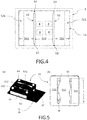
- Fig. 4 shows a principle sketch of another embodiment of the lighting arrangement 1 according to the present invention in a top view, wherein the stress release element 6 is established by two open slits 61, 62 executed as vertical slits 61, 62 through the optical sub-holder 51.
- the slits may have a width W ranging between 100 ⁇ m and 5mm.
- the two separate slits 61, 62 are arranged on both sides of the area of the optical holder 51 carrying four separate optical elements 4 (indicated by dashed square) in parallel to an edge of the connecting sub-holder 52 holding the optical sub-holder 51 facing towards the optical element 4.
- Fig.5 shows another embodiment of the lighting arrangement 1 according to the present invention (a) in a perspective view and (b) in a top view of the optical sub-holder 51.
- the lighting arrangement comprises a holder 5 comprising an optical sub-holder 51 and a connecting sub-holder 52 connecting the optical sub-holder 51 with the support member 3.
- the LED lighting element 2 is arranged underneath the optical sub-holder 51 between the connecting sub-holders 52 and therefore not visible here.
- the stress release element 6 comprises two slits 61, 62 with widths W varying along the length L of the slit 61, 62.
- the varying slits may be adapted to an optical element 4 comprising two or more element parts each serving specific beam shaping functions, wherein also the specific element parts are separated from each other by the stress release element 61, 62.
- Fig.6 shows the vertical displacement of lighting arrangements (a) according to prior art and (b) according to the present invention in a perspective view received from thermo-mechanical modelling of the assembly described above.
- interactions between all parts have been taken into account assuming a hard interaction in the direction normal to each interface in contact and interaction with a friction coefficient of 0.3 in the direction parallel to all interfaces in contact.
- the applied load is an uniform temperature increment corresponding to the automotive environment temperature variation during operation. Free stress temperature of all the parts is assumed to be the assembly temperature i.e ambient temperature ⁇ 20°C. Parts are fixed together by bolts. Local tightening and squeezing of the material around the bolts are not taken into account in the model.
- Simulation results of the assembly are obtained for a positive temperature increment to an operating temperature of 125°C, where the vertical displacement values for the upper surface of the optical sub-holder 52 are represented by contour lines across the lighting arrangement, where each area is denoted by the reference signs x1 - x8 for the local vertical displacement of 0,86 ⁇ x1 ⁇ 0,78mm ⁇ x2 ⁇ 0,70mm ⁇ x3 ⁇ 0,62mm ⁇ x4 ⁇ 0,54mm ⁇ x5 ⁇ 0,46mm ⁇ x6 ⁇ 0,38mm ⁇ x7 ⁇ 0,30mm x8 ⁇ 0,22mm).
- Magnified deformation and vertical displacement after positive temperature increment occur due to the CTE mismatch between Silicone and LCP holder material.
- the optical sub-holder (and therefore also the optical element 4) is strongly shifted toward the vertical direction.
- the outer area of the optical sub-holder 51 is completely detached from the connecting sub-holder 51 only carrying the optical sub-holder on small areas at the corners.
- the optical element 4 is displaced toward the upward direction and the gap between support member 3 and bottom surface of the optical element 4 is increased from 500 ⁇ m to more than 930 ⁇ m.
- the displacement of the optical sub-holders 51 in z direction is compared between the reference configuration ( fig.6a ) and the configuration with the design according to the present invention ( fig.6b ). As it could be seen, the vertical displacement is much more reduced for the configuration with design according to the present invention.
- the gap between support member 3 and the optical element 4 is increased by more than 430 ⁇ m.
- the gap increase is only equal to 30 ⁇ m.
- the main part 512 remains nearly in its initial position while the outer parts 511 are significantly deformed by thermal stress induced by the temperature of 125°C.
- introduction of opening slits 61, 62 in the optical sub-holder 51 allows to release the stress driven by contact of material with high CTE mismatch near connection areas between connecting sub-holder 52 and optical sub-holder 51s.
- the outer parts of the optical element and optical sub-holder made of silicone is free to deform and the displacement of the outer part has no impact on the collimators area.
- Fig. 7 shows an embodiment of the method 100 to manufacture a lighting arrangement 1 according to the present invention comprising the steps of providing 110 a support member 3 carrying at least one LED lighting element 2, providing 120 an optical sub-holder 51 carrying at least one optical element 4 to receive the light B emitted from the LED lighting element 2 and connecting 130 the optical sub-holder 51 via a connecting sub-holder 52 to the support member 3, where the optical sub-holder 51 and the connecting sub-holder 52 forming a holder 5, where the connecting sub-holder 52 is suitably shaped that the optical sub-holder 51 bridges the connecting sub-holder 52 to hold the optical element 4 in a desired position P1 relative to the LED lighting element 2 suitable to shape the received light B in a desired way.
- the support member might be a Cu IMS board with a coefficient of thermal expansion of 16ppm/°C or any other suitable material
- the holder optical sub-holder 51 and connecting sub-holder 52
- the optical element might be made of of silicone, e.g. a silicone lens having a coefficient of thermal expansion of 250ppm/°C or any other suitable material.
- the holder 5 is manufactured 150 via injection moulding, transfer moulding or stamping (as indicated by the dashed arrows).
- At least one stress release element 6, 61, 62 is introduced 140 into the optical sub-holder 51 dividing the optical sub-holder 51 in one or more outer parts 511 connected to the connecting sub-holder 52 and a main part 512 carrying the optical element 4, where a mechanical connection 53 between the main part 512 and the one or more outer parts 511 is weakened by the stress release element 6, 61, 62 extending through the optical sub-holder 51 and having a suitable shape and length L to maintain the required mechanical connection 53 between the main part 512 and the one or more outer parts 511 suitable to carry the main part 512 and to enable the one or more outer parts 511 to deform freely in case of thermal stress and to maintain a main part position P2 of the main part 512 being closer to the desired position P1 compared to an outer part position P3 of the one or more outer parts 511.
- the stress release element 6, 61, 62 might be also introduced at least partly into the connecting sub-holder 52.
- the step of introducing 140 the stress release element 6, 61, 62 is performed after having connected the optical sub-holder 51 to the connecting sub-holder 52.
Landscapes
- Engineering & Computer Science (AREA)
- General Engineering & Computer Science (AREA)
- Physics & Mathematics (AREA)
- Microelectronics & Electronic Packaging (AREA)
- Optics & Photonics (AREA)
- Manufacturing & Machinery (AREA)
- Mechanical Engineering (AREA)
- Led Device Packages (AREA)
- Non-Portable Lighting Devices Or Systems Thereof (AREA)
- Securing Globes, Refractors, Reflectors Or The Like (AREA)
- Fastening Of Light Sources Or Lamp Holders (AREA)
Abstract
Description
- The invention relates to a lighting arrangement comprising a specific holder to carry an optical element above a LED lighting element and to a method for manufacturing the lighting arrangement.
- Lighting arrangements with LEDs are used for an ever increasing number of lighting applications. In many cases, an optical element is arranged in front of an LED to alter the light emission, such as e.g. a lens, a reflector and/or a collimator to obtain an emitted light beam of desired properties. The properties of the emitted light may depend on the exact positioning of the optical element relative to the LED. An exact and stable positioning of the optical element relative to the LED is essential to maintain stable emission properties over a wide range of operating conditions. In case of providing a stable position by bringing the LEDs and the optical element in direct contact, there is a high risk of brittle failure of the LED material. Therefore any contact between LEDs and optical elements are commonly prevented by certain holders providing a gap between optical element and LED emitting surface, where the structure should be stable in the range of a few micrometers.
- Thermal changes, e.g. due to a change in ambient temperature or due to LED electrical operating power dissipated as heat, significantly influence such a holding structure provided to mount an optical element relative to an LED. In particular, if the structure supporting the LED and the optical element is comprised of different parts or different materials with a differing coefficient of thermal expansion (CTE), the structure may undergo distortions during negative or positive temperature increment that could lead to variations in the relative arrangement of the LED and the optical element.
- It would be desirable to provide a lighting arrangement with improved thermal stability of the positioning of the optical element having relatively low temperature sensitivity over a wide range of operating condition even for significant mismatches of the coefficients of thermal expansion of the materials of the components of the lighting arrangement.
- It is an object of the present invention to provide a lighting arrangement with improved thermal stability of the positioning of the optical element having relatively low temperature sensitivity over a wide range of operating condition even for significant mismatches of the coefficients of thermal expansion of the materials of the components of the lighting arrangement. Typical lighting arrangements comprise optical elements arranged in front of the light sources of the lighting arrangement, where the desired performance of the optical elements depends on the correct distance between optical element and light source. However thermal stress induced by varying operating conditions may cause variations of the distance between optical element and light source. Lighting arrangements suitable to keep the distance variation as small as possible provide a reliable and good optical performance of the lighting arrangement.
- The invention is defined by the independent claims. The dependent claims define advantageous embodiments.
- According to a first aspect a lighting arrangement is provided. The lighting arrangement comprises at least one LED lighting element arranged on a support member, at least one optical element to receive light emitted from the LED lighting element and a holder comprising an optical sub-holder and a connecting sub-holder connecting the optical sub-holder with the support member, where the connecting sub-holder is suitably shaped that the optical sub-holder bridges the connecting sub-holder to hold the optical element in a desired position relative to the LED lighting element suitable to shape the received light in a desired way, wherein at least the optical sub-holder comprises at least one stress release element dividing the optical sub-holder in one or more outer parts connected to the connecting sub-holder and a main part carrying the optical element, where a mechanical connection between the main part and the one or more outer parts is weakened by the stress release element extending through the optical sub-holder and having a suitable shape and length to maintain the required mechanical connection between the main part and the one or more outer parts suitable to carry the main part and to enable the one or more outer parts to deform freely in case of thermal stress while maintaining a main part position of the main part being closer to the desired position compared to an outer part position of the one or more outer parts.
- The term "lighting arrangement" denotes any assembly of components at least suitable to emit light. The lighting arrangement may be adapted to be connected to a operating and controlling unit or may comprise further components to control the light emission and/or supply energy to operated the lighting arrangement.
- The term "LED lighting element" denotes any type of solid state lighting element, such as e.g. light emitting diodes, organic light emitting diodes, laser diodes, etc. A LED lighting element may comprise a single or a plurality of such solid state lighting elements, e.g. one or a plurality of light emitting diodes arranged in close proximity in an emitting array.
- The term "support member" denotes any suitable substrate where the LED lighting element is mounted to. In an embodiment the support member might by a printed circuit board (PCB) adapted to operate the lighting arrangement, e.g. a Cu IMS board with a coefficient of thermal expansion of 16ppm/°C.
- The term "optical element" denotes any type of element with an optical function, in particular to alter the beam of light emitted from the LED lighting element. The optical element may thus comprise or be comprised of a reflector, a collimator, a lens, an optical filter, a baffle, etc, or a combination thereof. The optical element receives light from the LED lighting element in order to emit a modified beam, which may be e.g. focused, collimated, redirected, reflected, filtered etc. Optical elements may comprise or consist of silicone, e.g. a silicone lens having a coefficient of thermal expansion of 250ppm/°C.
- The term "holder" denotes a structure providing a mechanical connection between the optical element and the support member where the LED lighting element is mounted. The distance between the optical element and the emitting surface of the LED lighting element is defined by the mechanical construction of the holder, where the holder is designed as not to disturb the light path from the LED lighting element through the optical element to the environment. As an example the holder may comprise or consist of LCP having a coefficient of thermal expansion of 12ppm/°C providing sufficiently mechanical strength to hold the optical element.
- The term "bridges" denotes an arrangement of the connecting sub-holder and the optical sub-holder, where the connecting sub-holder is arranged outside the path of light and the optical sub-holder is supported by different parts of the connecting sub-holder while all together carrying the optical holder above the LED lighting element, where the optical sub-holder is not directly connected to the support member. The connecting sub-holder can be made of any material stable at high temperature, e.g. at 150°C, without or with low outgassing and with high stiffness, typically with E modulus higher than 1 GPa.
- The term "stress release element" denotes any arrangements suitable to weaken a mechanical connection between neighbored parts (here main part and adjacent outer part) within the optical sub-holder. The term "weaken" considers the requirement of maintaining a mechanical connection between neighbored parts in order to connect these parts to the connecting sub-holder, but decouples neighbored parts within a wide range of the optical sub-holder. Therefore the mechanical connection between main part and outer part(s) is still there but not as strong as in case of a present stress release element compared to an optical sub-holder without a stress release element. Examples for stress release elements are cuts, slits or openings through the optical sub-holder.
- In order to provide a stable position of the optical element, the main part of the optical sub-holder is connected via a mechanical connection to the connecting sub-holder at least via the outer parts of the optical sub-holder. However the mechanical connection is limited to small bars or bridges between the main part and the outer parts preferably arranged at the rim or close to the outer area of the optical sub-holder in order to prevent a fixed mechanical connection between the main part and the outer part in an area directly above or close to the optical element in a lateral direction parallel to the surface of the support member. This enables the outer parts of the optical sub-holder connected to the connection holder to deform more or less freely, where this deformation is not transferred to the main part of the optical sub-holder or at least strongly reduced.
- The special design of the optical holder leads to a release of compressive stress on the outer part of the optical sub-holder by introducing the stress release elements within the optical sub-holder. As a result, vertical displacements of the optical element due to induced thermal stress caused by varying operation conditions can be reduced by at least a factor of 10 compared to holders according to prior art. A short distance between LED lighting element and optical element is required to reduce optical losses. The special design of the optical sub-holder enables the arrangement of the optical element in such a short distance over a wide range of operation conditions with simultaneously preventing any contact between LED lighting element and optical elements in case of varying operation conditions. Therefore the special design of the optical sub-holder in the lighting arrangement according to the present invention provides a lighting arrangement with improved thermal stability of the positioning of the optical element having relatively low temperature sensitivity over a wide range of operating condition even for significant mismatches of the coefficients of thermal expansion of the materials of the components of the lighting arrangement.
- The lighting arrangement may be arranged in such a way that the stress release element is established by at least one open slit arranged between the main part and the connecting sub-holder. Slits instead of cuts fully decouples the main part from the outer part along the length of the slit of a certain width. Instead of this a cut destroys the direct mechanical connection between adjacent parts but does not introduce a gap between adjacent parts. Therefore friction forces between adjacent parts may transmit vertical displacements to a certain extend to the neighbored part. The imaging device may be arranged in such a way that the slit has a width ranging between 100µm and 5mm providing a even better mechanical decoupling between main and outer parts..
- The lighting arrangement may be arranged in such a way that the width of the slit varies along the length of the slit. A varied width along the length of the slit as the stress release element can be used to control lateral displacements of different optical elements arranged adjacent to each other on the same optical sub-holder to maintain constant gaps between these different optical elements.
- The lighting arrangement may be arranged in such a way that the slit is a vertical slit through the optical sub-holder. With a vertical slit the vertical displacements of the outer parts cannot affect the position of the main part of the optical sub-holder.
- The lighting arrangement may be arranged in such a way that the stress release element comprises at least two separate slits arranged on both sides of the area of the optical sub-holder carrying the optical element, preferably each slit being arranged in parallel to an edge of the connecting sub-holder holding the optical sub-holder facing towards the optical element. The two slits decouple the main part of the optical sub- holder from the outer parts being connected to the connecting sub-holder on both sides of the main part. In this embodiment, the vertical displacement of the main part of the optical sub- holder due to thermal stress is further reduced.
- The lighting arrangement may be arranged in such a way that the stress release element further extends at least partly into the connecting sub-holder in order to reduce the amount of vertical displacement introduced into the outer parts of the optical sub-holder from the connecting sub-holder.
- The lighting arrangement may be arranged in such a way that the optical element is at least partly made of a transparent or translucent material in order to be able to pass the light emitted from the LED lighting element at least partly through the optical element to the environment in a desired light beam direction.
- The lighting arrangement may be arranged in such a way that the optical element is arranged directly in front of a light emitting surface of the LED lighting element at a first distance, preferably along an optical axis along a main emission direction, to minimize light losses by light not entering into the optical elements.
- The lighting arrangement may be arranged in such a way that the optical element comprises two or more element parts each serving specific beam shaping functions, wherein also the specific element parts are separated from each other by the stress release element. In this case, the target is to place the element parts of the optical element as close as possible to each other, e.g. in order to focus the light as well as possible with a common 2nd element part. But in this case, direct contact between element parts has to be prevented to not mix the light between each functional part. A possible application of this configuration is a system where the high beam and low beam light functions are extracted from different element parts of the optical element. The corresponding lighting arrangement is even more efficient as it allows to reduce the lateral displacement and therefore to prevent contact between high and low beam element parts.
- The lighting arrangement may be arranged in such a way that the connecting sub-holder provides a supporting surface for the optical sub-holder, which is arranged at least on opposite sides of the LED lighting element in lateral direction parallel to the surface of the support member. This arrangement simplifies bridging of the optical sub-holder.
- The lighting arrangement may be arranged in such a way that the connecting sub-holder, the optical sub-holder and the optical element are provided as a single piece element made of the same material, e.g. made of silicone. A single piece element makes manufacturing more easily. However without the inventive concept of introducing a stress release element such a single piece element would be very sensible to temperature variations. This is not the case of a single piece element comprising a stress release element according to the present invention.
- According to a second aspect a method to manufacture a lighting arrangement is provided. The method comprises the steps of
- Providing a support member carrying at least one LED lighting element,
- Providing an optical sub-holder carrying at least one optical element to receive the light emitted from the LED lighting element,
- Connecting the optical sub-holder via a connecting sub-holder to the support member, where the optical sub-holder and the connecting sub-holder forming a holder, where the connecting sub-holder is suitably shaped that the optical sub-holder bridges the connecting sub-holder to hold the optical element in a desired position relative to the LED lighting element suitable to shape the received light in a desired way,
- Introducing at least one stress release element into the optical sub-holder dividing the optical sub-holder in one or more outer parts connected to the connecting sub-holder and a main part carrying the optical element, where a mechanical connection between the main part and the one or more outer parts is weakened by the stress release element extending through the optical sub-holder and having a suitable shape and length to maintain the required mechanical connection between the main part and the one or more outer parts suitable to carry the main part and to enable the one or more outer parts to deform freely in case of thermal stress and to maintain a main part position of the main part being closer to the desired position compared to an outer part position of the one or more outer parts.
- The method may be performed in such a way that the step of introducing the stress release element is performed after having connected the optical sub-holder to the connecting sub-holder. Here additional stress introduced by the procedure of fixing the optical sub-holder to the connecting sub-holder can be released by introducing the stress release element and therefore cannot further contribute to any vertical displacements later on, leading to an even more stable position of the optical element relative to the LED lighting element..
- The method may be performed in such a way that the stress release element is also introduced at least partly into the connecting sub-holder.
- The method may be performed in such a way that the holder is manufactured via injection moulding, transfer moulding or stamping in order to manufacture the holder with a low cost process. As an example for injection molding, a thermal curing polymer is introduced in a cavity mold which has the negative shape of the targeted shape. To produce the slits, the cavity holding the thermal curing polymer is simply filled by material at the location corresponding to the slits.
- It shall be understood that a preferred embodiment of the invention can also be any combination of the dependent claims with the respective independent claim.
- Further advantageous embodiments are defined below.
- These and other aspects of the invention will be apparent from and elucidated with reference to the embodiments described hereinafter.
- The invention will now be described, by way of example, based on embodiments with reference to the accompanying drawings.
- In the drawings:
- Fig. 1
- shows a principle sketch of a lighting arrangement according to prior art.
- Fig. 2
- shows a principle sketch of a lighting arrangement according to the present invention in a top view.
- Fig. 3
- shows a principle sketch of the lighting arrangement of
fig.2 in a side view along section plane A-B (a) in case of no thermal stress and (b) in case of thermal stress induced by operating conditions. - Fig. 4
- shows a principle sketch of another embodiment of the lighting arrangement according to the present invention in a top view.
- Fig. 5
- shows another embodiment of the lighting arrangement according to the present invention (a) in a perspective view and (b) in a top view of the optical sub-holder.
- Fig. 6
- shows the vertical displacement of lighting arrangements (a) according to prior art and (b) according to the present invention in a perspective view.
- Fig. 7
- shows an embodiment of the method to manufacture a lighting arrangement according to the present invention.
- In the Figures, like numbers refer to like objects throughout. Objects in the Figs. are not necessarily drawn to scale.
- Various embodiments of the invention will now be described by means of the Figures.
-
Fig. 1 shows a principle sketch of a lighting arrangement according to prior art comprising aLED lighting element 2 with alight emitting surface 21 arranged on aupper surface 31 of asupport member 3, where a collimator as anoptical element 4 is arranged above thelight emitting surface 21 in order to receive light B emitted from theLED lighting element 2. Thecollimator 4 is carried by a holder not shown here. Typical distances are 100µm for the distance D2 between light emittingsurface 21 andcollimator 4 and 500µm for the distance D3 betweenupper surface 31 of thesupport member 3 andcollimator 4. The amount of light B emitted from theLED lighting element 2 with an indicated emitting conus entering thecollimator 4 depends on the distance D2. In case of vertical displacements (indicated by the large error) of thecollimator 4 along the optical axis OA, the amount of light will vary leading to loss of non collimated light missing thecollimator 4 on both sides in case of an increased distance D2 and also due to the increase of rays hitting the internal collimators face with an angle higher than the critical internal reflection angle. A loss of light might be reduced in case of decreasing the distance D2. However, due to vertical displacements the distance D2 may decrease to zero resulting in a contact betweencollimator 4 and thelight emitting surface 21 eventually leading to damages of theLED lighting element 2. Therefore a reliable distance is essential for the performance of a lighting arrangement, which can be achieved by the lighting arrangement according to the present invention comprising a holder with a specific design. -
Fig. 2 shows a principle sketch of alighting arrangement 1 according to the present invention in a top view, where the details between optical sub-holder 51 and support member 3 (dashed area underneath the optical sub-holder 51) are shown infig.3 . Theholder 5 comprises anoptical sub-holder 51 and a connectingsub-holder 52 connecting theoptical sub-holder 51 with thesupport member 3, where, in this embodiment, the connectingsub-holder 52 comprises a left part and a right part arranged on opposite sides of theLED lighting element 2 in lateral direction parallel to thesurface 31 of thesupport member 3 with each part of the connecting sub-holder having a supportingsurface 521 to carry theoptical sub-holder 51. When mounted on the supportingsurfaces 521 the optical sub-holder 51 bridges the connectingsub-holder 52 to hold the optical element 4 (indicated as dashed square) in a desired position P1 above theLED lighting element 2. Here theoptical sub-holder 51 comprises astress release element 6 provided on each side of theoptical element 4 between optical element and connectingsub-holder 52 dividing theoptical sub-holder 51 in twoouter parts 511 directly connected to the connectingsub-holder 52 and amain part 512 carrying theoptical element 4, where amechanical connection 53 between themain part 512 and the twoouter parts 511 is weakened by thestress release element 6 extending through theoptical sub-holder 51 as cuts (indicated by the solid lines) having a length L to maintain the requiredmechanical connection 53 between themain part 512 and the twoouter parts 511 close to the edger of theoptical sub-holder 51 to reliably carry themain part 512 and simultaneously to enable the twoouter parts 511 to deform freely in case of thermal stress while maintaining a main part position P2 of themain part 512. -
Fig. 3 shows a principle sketch of thelighting arrangement 1 offig.2 in a side view along section plane A-B (a) in case of no thermal stress and (b) in case of thermal stress induced by operating conditions. In this embodiment thelighting arrangement 1 comprises oneLED lighting element 2 arranged centrally on anupper surface 31 of asupport member 3, oneoptical element 4 to received light B emitted from theLED lighting element 2 wherein theoptical element 4 and theoptical sub-holder 51 are at least partly made of a transparent or translucent material in order to emit light B to the environment. Here theoptical element 4 is arranged directly in front of alight emitting surface 21 of theLED lighting element 2 at a first distance D2 along an optical axis OA along a main emission direction. Theoptical element 4 might be made of silicone. The advantage of this configuration is that the deformation of theholder 5 can be controlled by choosing holder material with CTE matching the board CTE. It would not be possible if theoptical element 4 was supporting itself as usually the CTE of optical element is very high. Thelighting arrangement 1 further comprises aholder 5 comprising anoptical sub-holder 51 and a connectingsub-holder 52 connecting theoptical sub-holder 51 with thesupport member 3, where the optical sub-holder 51 bridges the connectingsub-holders 52 right and left of theLED lighting element 2 to hold theoptical element 4 in the desired position P1 relative to theLED lighting element 2 to shape the received light B in a desired way. Thestress release element 6 divides theoptical sub-holder 51 in twoouter parts 511 connected to the connectingsub-holder 52 and amain part 512 carrying theoptical element 4. The stress release element 6 (indicated by dashed lines) extend through theoptical sub-holder 51 on both sides of theoptical element 4 as a vertical cut. In case of no induced thermal stress (Fig.2a ) theouter parts 511 and themain part 512 have the same position (distance) to thesurface 31 of thesupport member 3 or thelight emitting surface 21 of theLED lighting element 2. In case of induced thermal stress (Fig.2b ) thestress release element 6 executed as cuts lead to a maintained main part position P2 of themain part 512, while the adjacentouter parts 511 of theoptical sub-holder 51 left and right to themain part 511 are free to deform resulting in a vertical displacement to an outer part position P3 of the twoouter parts 511, which has a larger vertical distance to thelight emitting surface 21 as the main part at the main part position P2. The requiredmechanical connections 53 are located outside the section plane A-B and therefore not shown here. -
Fig. 4 shows a principle sketch of another embodiment of thelighting arrangement 1 according to the present invention in a top view, wherein thestress release element 6 is established by twoopen slits vertical slits optical sub-holder 51. The slits may have a width W ranging between 100µm and 5mm. Here the twoseparate slits optical holder 51 carrying four separate optical elements 4 (indicated by dashed square) in parallel to an edge of the connectingsub-holder 52 holding theoptical sub-holder 51 facing towards theoptical element 4. -
Fig.5 shows another embodiment of thelighting arrangement 1 according to the present invention (a) in a perspective view and (b) in a top view of theoptical sub-holder 51. The lighting arrangement comprises aholder 5 comprising anoptical sub-holder 51 and a connectingsub-holder 52 connecting theoptical sub-holder 51 with thesupport member 3. TheLED lighting element 2 is arranged underneath theoptical sub-holder 51 between the connectingsub-holders 52 and therefore not visible here. In this embodiment thestress release element 6 comprises twoslits slit optical element 4 comprising two or more element parts each serving specific beam shaping functions, wherein also the specific element parts are separated from each other by thestress release element -
Fig.6 shows the vertical displacement of lighting arrangements (a) according to prior art and (b) according to the present invention in a perspective view received from thermo-mechanical modelling of the assembly described above. In this model, interactions between all parts have been taken into account assuming a hard interaction in the direction normal to each interface in contact and interaction with a friction coefficient of 0.3 in the direction parallel to all interfaces in contact. For simplification, the applied load is an uniform temperature increment corresponding to the automotive environment temperature variation during operation. Free stress temperature of all the parts is assumed to be the assembly temperature i.e ambient temperature ∼20°C. Parts are fixed together by bolts. Local tightening and squeezing of the material around the bolts are not taken into account in the model. The used mechanical properties for the simulation are given in table 1, where E denotes the Youngs module and CTZE the coefficient of thermal expansion.Table 1: mechanical properties used for the modeling of vertical displacements Component Material E (MPa) CTE (ppm/°C) Connecting sub-holder LCP 15.500 12 Optical element and optical sub-holder silicone 16 250 Support member Cu IMS board 130.000 16 - Simulation results of the assembly are obtained for a positive temperature increment to an operating temperature of 125°C, where the vertical displacement values for the upper surface of the
optical sub-holder 52 are represented by contour lines across the lighting arrangement, where each area is denoted by the reference signs x1 - x8 for the local vertical displacement of 0,86 < x1 < 0,78mm < x2 < 0,70mm < x3 <0,62mm < x4 < 0,54mm < x5 < 0,46mm < x6 < 0,38mm < x7 <0,30mm x8 <0,22mm). Magnified deformation and vertical displacement after positive temperature increment occur due to the CTE mismatch between Silicone and LCP holder material. Infig 6a the optical sub-holder (and therefore also the optical element 4) is strongly shifted toward the vertical direction. The outer area of theoptical sub-holder 51 is completely detached from the connectingsub-holder 51 only carrying the optical sub-holder on small areas at the corners. As a result, theoptical element 4 is displaced toward the upward direction and the gap betweensupport member 3 and bottom surface of theoptical element 4 is increased from 500 µm to more than 930 µm. The displacement of the optical sub-holders 51 in z direction is compared between the reference configuration (fig.6a ) and the configuration with the design according to the present invention (fig.6b ). As it could be seen, the vertical displacement is much more reduced for the configuration with design according to the present invention. For example, after positive temperature increment, the gap betweensupport member 3 and theoptical element 4 is increased by more than 430 µm. However, for the configuration with design according to the present invention, the gap increase is only equal to 30 µm. Themain part 512 remains nearly in its initial position while theouter parts 511 are significantly deformed by thermal stress induced by the temperature of 125°C. In conclusion, introduction of opening slits 61, 62 in theoptical sub-holder 51 allows to release the stress driven by contact of material with high CTE mismatch near connection areas between connectingsub-holder 52 and optical sub-holder 51s. As a result, the outer parts of the optical element and optical sub-holder made of silicone is free to deform and the displacement of the outer part has no impact on the collimators area. -
Fig. 7 shows an embodiment of themethod 100 to manufacture alighting arrangement 1 according to the present invention comprising the steps of providing 110 asupport member 3 carrying at least oneLED lighting element 2, providing 120 anoptical sub-holder 51 carrying at least oneoptical element 4 to receive the light B emitted from theLED lighting element 2 and connecting 130 theoptical sub-holder 51 via a connectingsub-holder 52 to thesupport member 3, where theoptical sub-holder 51 and the connectingsub-holder 52 forming aholder 5, where the connectingsub-holder 52 is suitably shaped that the optical sub-holder 51 bridges the connectingsub-holder 52 to hold theoptical element 4 in a desired position P1 relative to theLED lighting element 2 suitable to shape the received light B in a desired way. Here the support member might be a Cu IMS board with a coefficient of thermal expansion of 16ppm/°C or any other suitable material, the holder (optical sub-holder 51 and connecting sub-holder 52) might be made of LCP having a coefficient of thermal expansion of 12ppm/°C or any other suitable material and the optical element might be made of of silicone, e.g. a silicone lens having a coefficient of thermal expansion of 250ppm/°C or any other suitable material. In an embodiment theholder 5 is manufactured 150 via injection moulding, transfer moulding or stamping (as indicated by the dashed arrows). In a further step at least onestress release element optical sub-holder 51 dividing theoptical sub-holder 51 in one or moreouter parts 511 connected to the connectingsub-holder 52 and amain part 512 carrying theoptical element 4, where amechanical connection 53 between themain part 512 and the one or moreouter parts 511 is weakened by thestress release element optical sub-holder 51 and having a suitable shape and length L to maintain the requiredmechanical connection 53 between themain part 512 and the one or moreouter parts 511 suitable to carry themain part 512 and to enable the one or moreouter parts 511 to deform freely in case of thermal stress and to maintain a main part position P2 of themain part 512 being closer to the desired position P1 compared to an outer part position P3 of the one or moreouter parts 511. Here thestress release element sub-holder 52. In the embodiment shown here the step of introducing 140 thestress release element optical sub-holder 51 to the connectingsub-holder 52. - While the invention has been illustrated and described in detail in the drawings and the foregoing description, such illustration and description are to be considered illustrative or exemplary and not restrictive.
- From reading the present disclosure, other modifications will be apparent to persons skilled in the art. Such modifications may involve other features which are already known in the art and which may be used instead of or in addition to features already described herein.
- Variations to the disclosed embodiments can be understood and effected by those skilled in the art, from a study of the drawings, the disclosure and the appended claims. In the claims, the word "comprising" does not exclude other elements or steps, and the indefinite article "a" or "an" does not exclude a plurality of elements or steps. The mere fact that certain measures are recited in mutually different dependent claims does not indicate that a combination of these measures cannot be used to advantage.
- Any reference signs in the claims should not be construed as limiting the scope thereof.
-
- 1
- Lighting arrangement
- 2
- LED lighting element
- 21
- Light emitting surface of the LED lighting element
- 3
- Support member
- 31
- (upper) surface of the support member
- 4
- Optical element
- 5
- Holder
- 51
- optical sub-holder
- 511
- outer part of the optical sub-holder
- 512
- main part of the optical sub-holder
- 52
- connecting sub-holder
- 521
- supporting surface of the connecting sub-holder to support the optical sub-holder
- 53
- mechanical connection between main part and outer part
- 6
- stress release element
- 61, 62
- slit (first and second)
- 100
- method to manufacture the
lighting arrangement 1 - 110
- Providing a support member carrying the LED lighting element
- 120
- Providing an optical sub-holder carrying the optical element
- 130
- Connecting the optical sub-holder via the connecting sub-holder to the support member
- 140
- Introducing the stress release element into the optical sub-holder
- 150
- manufactured the holder via injection moulding, transfer moulding or stamping
- A-B
- section plane for
fig.3 - B
- Light emitted from the LED lighting element
- D2
- first distance (between light emitting surface and optical element)
- D3
- distance between surface of support member and optical element
- L
- length of the slit
- OA
- optical axis
- P1
- Desired position of optical element and optical sub-holder
- P2
- main part position
- P3
- outer part position
- W
- width of the slit
- x1 - x8
- Positions with a certain vertical displacement with respect to the support member
Claims (16)
- A lighting arrangement (1) comprising at least one LED lighting element (2) arranged on a support member (3), at least one optical element (4) to received light (B) emitted from the LED lighting element (2) and a holder (5) comprising an optical sub-holder (51) and a connecting sub-holder (52) connecting the optical sub-holder (51) with the support member (3), where the connecting sub-holder (52) is suitable shaped that the optical sub-holder (51) bridges the connecting sub-holder (52) to hold the optical element (4) in a desired position (P1) relative to the LED lighting element (2) suitable to shape the received light (B) in a desired way, wherein at least the optical sub-holder (51) comprises at least one stress release element (6, 61, 62) dividing the optical sub-holder (51) in one or more outer parts (511) connected to the connecting sub-holder (52) and a main part (512) carrying the optical element (4), where a mechanical connection (53) between the main part (512) and the one or more outer parts (511) is weakened by the stress release element (6, 61, 62) extending through the optical sub-holder (51) and having a suitable shape and length (L) to maintain the required mechanical connection (53) between the main part (512) and the one or more outer parts (511) suitable to carry the main part (512) and to enable the one or more outer parts (511) to deform freely in case of thermal stress while maintaining a main part position (P2) of the main part (512) being closer to the desired position (P1) compared to an outer part position (P3) of the one or more outer parts (511).
- The lighting arrangement (1) in accordance with claim 1, wherein the stress release element (6) is established by at least one open slit (61, 62) arranged between the main part (512) and the connecting sub-holder (52).
- The lighting arrangement (1) in accordance with claim 2, wherein the slit has a width (W) ranging between 100µm and 5mm.
- The lighting arrangement (1) in accordance with claim 2 or 3, wherein the width (W) of the slit (61, 62) varies along the length (L) of the slit (61, 62).
- The lighting arrangement (1) in accordance with claim 2 or 4, wherein the slit (61, 62) is vertical slit through the optical sub-holder (51).
- The lighting arrangement (1) in accordance with claim 2 or 5, wherein the stress release element (6) comprises at least two separate slits (61, 62) arranged on both sides of the area of the optical holder (51) carrying the optical element (4), preferably each slit (61, 62) being arranged in parallel to an edge of the connecting sub-holder (52) holding the optical sub-holder (51) facing towards the optical element (4).
- The lighting arrangement (1) in accordance with one of the preceding claims, wherein the stress release element (6, 61, 62) further extends at least partly into the connecting sub-holder (52).
- The lighting arrangement (1) in accordance with one of the preceding claims, wherein the optical element (4) is at least partly made of a transparent or translucent material.
- The lighting arrangement (1) in accordance with one of the preceding claims, wherein the optical element (4) is arranged directly in front of a light emitting surface (21) of the LED lighting element (2) at a first distance (D2), preferably along an optical axis (OA) along a main emission direction.
- The lighting arrangement (1) in accordance with one of the preceding claims, wherein the optical element (4) comprises two or more element parts each serving specific beam shaping functions, wherein also the specific element parts are separated from each other by the stress release element (6, 61, 62).
- The lighting arrangement (1) in accordance with one of the preceding claims, wherein the connecting sub-holder (52) provides a supporting surface (521) for the optical sub-holder (51), which is arranged at least on opposite sides of the LED lighting element (2) in lateral direction parallel to the surface (31) of the support member (3).
- The lighting arrangement (1) in accordance with one of the preceding claims, wherein the connecting sub-holder (52), the optical sub-holder (51) and the optical element (4) are provided as a single piece element made of the same material.
- A method (100) to manufacture a lighting arrangement (1) according to claim 1 comprising the steps of- Providing (110) a support member (3) carrying at least one LED lighting element (2),- Providing (120) an optical sub-holder (51) carrying at least one optical element (4) to receive the light (B) emitted from the LED lighting element (2),- Connecting (130) the optical sub-holder (51) via a connecting sub-holder (52) to the support member (3), where the optical sub-holder (51) and the connecting sub-holder (52) forming a holder (5), where the connecting sub-holder (52) is suitably shaped that the optical sub-holder (51) bridges the connecting sub-holder (52) to hold the optical element (4) in a desired position (P1) relative to the LED lighting element (2) suitable to shape the received light (B) in a desired way,- Introducing (140) at least one stress release element (6, 61, 62) into the optical sub-holder (51) dividing the optical sub-holder (51) in one or more outer parts (511) connected to the connecting sub-holder (52) and a main part (512) carrying the optical element (4), where a mechanical connection (53) between the main part (512) and the one or more outer parts (511) is weakened by the stress release element (6, 61, 62) extending through the optical sub-holder (51) and having a suitable shape and length (L) to maintain the required mechanical connection (53) between the main part (512) and the one or more outer parts (511) suitable to carry the main part (512) and to enable the one or more outer parts (511) to deform freely in case of thermal stress and to maintain a main part position (P2) of the main part (512) being closer to the desired position (P1) compared to an outer part position (P3) of the one or more outer parts (511).
- The method (100) according to claim 13, wherein the step of introducing (140) the stress release element (6, 61, 62) is performed after having connected the optical sub-holder (51) to the connecting sub-holder (52).
- The method (100) according to claim 13 or 14, wherein the stress release element (6, 61, 62) is also introduced at least partly into the connecting sub-holder (52).
- The method (100) according to one of claims 13 to 15, wherein the holder (5) is manufactured (150) via injection moulding, transfer moulding or stamping.
Priority Applications (5)
| Application Number | Priority Date | Filing Date | Title |
|---|---|---|---|
| EP17161501.6A EP3376099B1 (en) | 2017-03-17 | 2017-03-17 | Led lighting arrangement |
| JP2018046373A JP6357600B1 (en) | 2017-03-17 | 2018-03-14 | LED lighting device |
| US15/921,939 US10208929B2 (en) | 2017-03-17 | 2018-03-15 | LED lighting arrangement |
| KR1020180030769A KR102543885B1 (en) | 2017-03-17 | 2018-03-16 | Led lighting arrangement |
| CN201810219005.1A CN108626586B (en) | 2017-03-17 | 2018-03-16 | LED lighting device |
Applications Claiming Priority (1)
| Application Number | Priority Date | Filing Date | Title |
|---|---|---|---|
| EP17161501.6A EP3376099B1 (en) | 2017-03-17 | 2017-03-17 | Led lighting arrangement |
Publications (2)
| Publication Number | Publication Date |
|---|---|
| EP3376099A1 true EP3376099A1 (en) | 2018-09-19 |
| EP3376099B1 EP3376099B1 (en) | 2019-09-18 |
Family
ID=58360899
Family Applications (1)
| Application Number | Title | Priority Date | Filing Date |
|---|---|---|---|
| EP17161501.6A Active EP3376099B1 (en) | 2017-03-17 | 2017-03-17 | Led lighting arrangement |
Country Status (5)
| Country | Link |
|---|---|
| US (1) | US10208929B2 (en) |
| EP (1) | EP3376099B1 (en) |
| JP (1) | JP6357600B1 (en) |
| KR (1) | KR102543885B1 (en) |
| CN (1) | CN108626586B (en) |
Cited By (1)
| Publication number | Priority date | Publication date | Assignee | Title |
|---|---|---|---|---|
| WO2020193117A1 (en) | 2019-03-26 | 2020-10-01 | Lumileds Holding B.V. | Lighting device with transparent stabilizer element |
Families Citing this family (2)
| Publication number | Priority date | Publication date | Assignee | Title |
|---|---|---|---|---|
| KR102619113B1 (en) * | 2019-01-14 | 2023-12-27 | 무스코 코포레이션 | Apparatus, method and system for reducing moisture in LED lighting fixtures |
| US11655966B2 (en) | 2019-01-14 | 2023-05-23 | Musco Corporation | Apparatus, method, and system for reducing moisture in LED lighting fixtures |
Citations (6)
| Publication number | Priority date | Publication date | Assignee | Title |
|---|---|---|---|---|
| US4884869A (en) * | 1986-11-11 | 1989-12-05 | Dainippon Screen Mfg., Co., Ltd. | Fly's eye lens unit for illumination system |
| JPH11213733A (en) * | 1998-01-22 | 1999-08-06 | Kuroi Electric Co Ltd | Abnormal noise generation prevention equipment for lighting equipment |
| US20020044456A1 (en) * | 2000-08-22 | 2002-04-18 | Christophe Balestriero | Luminaire based on the light emission of light-emitting diodes |
| US20020113244A1 (en) * | 2001-02-22 | 2002-08-22 | Barnett Thomas J. | High power LED |
| WO2012048281A1 (en) * | 2010-10-08 | 2012-04-12 | Soraa, Inc. | High intensity light source |
| US20170073048A1 (en) * | 2015-09-14 | 2017-03-16 | Trent Neil Butcher | Lighting devices including at least one light-emitting device, systems including at least one lighting device, and related methods |
Family Cites Families (22)
| Publication number | Priority date | Publication date | Assignee | Title |
|---|---|---|---|---|
| JP2003098407A (en) * | 2001-09-26 | 2003-04-03 | Nec Compound Semiconductor Devices Ltd | Semiconductor optical coupling device |
| US7942548B2 (en) * | 2006-01-17 | 2011-05-17 | Mitsubishi Heavy Industries, Ltd. | Light-source lamp and projector |
| TWM310984U (en) * | 2006-11-28 | 2007-05-01 | Primo Lite Co Ltd | Lamp structure of light emitting diode |
| US7942556B2 (en) * | 2007-06-18 | 2011-05-17 | Xicato, Inc. | Solid state illumination device |
| US7654690B2 (en) * | 2008-01-13 | 2010-02-02 | Tang Shih Chuan | Lampshade for a light-emitting diode (LED) lamp |
| JP4879218B2 (en) * | 2008-04-25 | 2012-02-22 | シャープ株式会社 | Lens body, light source unit, and illumination device |
| CN101619822B (en) * | 2008-06-30 | 2012-12-19 | 鸿富锦精密工业(深圳)有限公司 | Lighting device |
| US7891842B2 (en) * | 2008-08-07 | 2011-02-22 | Hong Kong Applied Science And Technology Research Institute Co. Ltd. | Heat-dissipating reflector for lighting device |
| US8684563B2 (en) * | 2008-12-30 | 2014-04-01 | Kitagawa Holdings, Llc | Heat dissipating structure of LED lamp cup made of porous material |
| US8157419B2 (en) * | 2009-08-26 | 2012-04-17 | Abl Ip Holding Llc | LED assembly |
| US20110181165A1 (en) * | 2010-01-22 | 2011-07-28 | Shun-Tian Lin | Light emitting diode lamp |
| WO2011130648A2 (en) * | 2010-04-16 | 2011-10-20 | Solais Lighting, Inc. | Miniature cellular structure for retrofit led lamp secondary optics |
| CN102449382B (en) * | 2010-06-02 | 2015-06-03 | 松下电器产业株式会社 | Lamp and lighting device |
| TWM403609U (en) * | 2010-12-02 | 2011-05-11 | Nexgen Mediatech Inc | Illumination device and lamp housing having both heat-dissipation and light source diffusion functions |
| US8829774B1 (en) * | 2011-02-11 | 2014-09-09 | Soraa, Inc. | Illumination source with direct die placement |
| US20140091697A1 (en) * | 2011-02-11 | 2014-04-03 | Soraa, Inc. | Illumination source with direct die placement |
| CN102705657B (en) * | 2012-06-15 | 2014-10-15 | 中国科学院长春光学精密机械与物理研究所 | Flexible support frame for small high-stability multifunctional optical reflector |
| JP6045829B2 (en) * | 2012-07-13 | 2016-12-14 | 日東電工株式会社 | Opto-electric hybrid board |
| JP2014082348A (en) * | 2012-10-17 | 2014-05-08 | Seiko Epson Corp | Package for storing optical element, optical filter device, optical module, and electronic apparatus |
| DE102012223860B4 (en) * | 2012-12-19 | 2023-05-11 | Ledvance Gmbh | lighting device |
| JP2014154230A (en) * | 2013-02-05 | 2014-08-25 | Toshiba Lighting & Technology Corp | Lamp device, light-emitting device, and lighting device |
| JP2016092271A (en) * | 2014-11-06 | 2016-05-23 | シャープ株式会社 | Phosphor sheet and lighting system |
-
2017
- 2017-03-17 EP EP17161501.6A patent/EP3376099B1/en active Active
-
2018
- 2018-03-14 JP JP2018046373A patent/JP6357600B1/en active Active
- 2018-03-15 US US15/921,939 patent/US10208929B2/en active Active
- 2018-03-16 CN CN201810219005.1A patent/CN108626586B/en active Active
- 2018-03-16 KR KR1020180030769A patent/KR102543885B1/en active Active
Patent Citations (6)
| Publication number | Priority date | Publication date | Assignee | Title |
|---|---|---|---|---|
| US4884869A (en) * | 1986-11-11 | 1989-12-05 | Dainippon Screen Mfg., Co., Ltd. | Fly's eye lens unit for illumination system |
| JPH11213733A (en) * | 1998-01-22 | 1999-08-06 | Kuroi Electric Co Ltd | Abnormal noise generation prevention equipment for lighting equipment |
| US20020044456A1 (en) * | 2000-08-22 | 2002-04-18 | Christophe Balestriero | Luminaire based on the light emission of light-emitting diodes |
| US20020113244A1 (en) * | 2001-02-22 | 2002-08-22 | Barnett Thomas J. | High power LED |
| WO2012048281A1 (en) * | 2010-10-08 | 2012-04-12 | Soraa, Inc. | High intensity light source |
| US20170073048A1 (en) * | 2015-09-14 | 2017-03-16 | Trent Neil Butcher | Lighting devices including at least one light-emitting device, systems including at least one lighting device, and related methods |
Cited By (2)
| Publication number | Priority date | Publication date | Assignee | Title |
|---|---|---|---|---|
| WO2020193117A1 (en) | 2019-03-26 | 2020-10-01 | Lumileds Holding B.V. | Lighting device with transparent stabilizer element |
| DE212020000556U1 (en) | 2019-03-26 | 2021-11-23 | Lumileds Llc | Lighting device with transparent stabilizer element |
Also Published As
| Publication number | Publication date |
|---|---|
| KR20180106962A (en) | 2018-10-01 |
| US20180266663A1 (en) | 2018-09-20 |
| CN108626586A (en) | 2018-10-09 |
| KR102543885B1 (en) | 2023-06-16 |
| JP2018156939A (en) | 2018-10-04 |
| US10208929B2 (en) | 2019-02-19 |
| CN108626586B (en) | 2021-11-23 |
| EP3376099B1 (en) | 2019-09-18 |
| JP6357600B1 (en) | 2018-07-11 |
Similar Documents
| Publication | Publication Date | Title |
|---|---|---|
| KR102471307B1 (en) | laser projection module | |
| EP3371512B1 (en) | Reducing thermal sensitivity of a lighting arrangement | |
| EP3376099B1 (en) | Led lighting arrangement | |
| CN102171509B (en) | A mounting arrangement for lighting devices, corresponding lighting device and method | |
| US7324717B2 (en) | Photonic device with integrated hybrid microlens array | |
| KR20090023688A (en) | Lighting device and manufacturing method thereof | |
| US20170363266A1 (en) | Optical unit for a headlight, optics arrangement and headlight | |
| CN106796009B (en) | Device for positioning a module comprising a light source on an optical device | |
| CN107924038B (en) | Optical member and light irradiation device | |
| US20130259421A1 (en) | Method of manufacturing optical waveguide device and optical waveguide device | |
| US7686224B2 (en) | Lensed dual diode-laser bar package | |
| WO2016020218A1 (en) | Led device with flexible thermal interface | |
| Moench et al. | Integrated high power VCSEL systems | |
| US20180238508A1 (en) | Light source module | |
| KR102408659B1 (en) | Light emitting device, and method of manufacturing the light emitting device | |
| US20220021189A1 (en) | Laser device and method for manufacturing a laser device | |
| JP2021044337A (en) | Semiconductor laser device | |
| US10429012B2 (en) | Method of fabricating a light emitting device with optical element | |
| KR102794546B1 (en) | Light irradiation device | |
| US9882346B2 (en) | Laser module with simplified alignment | |
| US10386587B2 (en) | Optical fiber fixation structure, semiconductor laser module, and method of manufacturing semiconductor laser module | |
| US20210050493A1 (en) | Optoelectronic Semiconductor Device and Method for Producing an Optoelectronic Semiconductor Device | |
| KR20260060973A (en) | Infrared heater and/or dryer | |
| US20150077988A1 (en) | Illumination device | |
| CN121285712A (en) | Optical lens assembly |
Legal Events
| Date | Code | Title | Description |
|---|---|---|---|
| PUAI | Public reference made under article 153(3) epc to a published international application that has entered the european phase |
Free format text: ORIGINAL CODE: 0009012 |
|
| STAA | Information on the status of an ep patent application or granted ep patent |
Free format text: STATUS: THE APPLICATION HAS BEEN PUBLISHED |
|
| AK | Designated contracting states |
Kind code of ref document: A1 Designated state(s): AL AT BE BG CH CY CZ DE DK EE ES FI FR GB GR HR HU IE IS IT LI LT LU LV MC MK MT NL NO PL PT RO RS SE SI SK SM TR |
|
| AX | Request for extension of the european patent |
Extension state: BA ME |
|
| RAP1 | Party data changed (applicant data changed or rights of an application transferred) |
Owner name: LUMILEDS HOLDING B.V. |
|
| STAA | Information on the status of an ep patent application or granted ep patent |
Free format text: STATUS: REQUEST FOR EXAMINATION WAS MADE |
|
| 17P | Request for examination filed |
Effective date: 20190319 |
|
| RBV | Designated contracting states (corrected) |
Designated state(s): AL AT BE BG CH CY CZ DE DK EE ES FI FR GB GR HR HU IE IS IT LI LT LU LV MC MK MT NL NO PL PT RO RS SE SI SK SM TR |
|
| RIC1 | Information provided on ipc code assigned before grant |
Ipc: F21V 29/10 20150101ALI20190408BHEP Ipc: F21V 17/06 20060101AFI20190408BHEP Ipc: F21Y 115/10 20160101ALN20190408BHEP |
|
| GRAP | Despatch of communication of intention to grant a patent |
Free format text: ORIGINAL CODE: EPIDOSNIGR1 |
|
| STAA | Information on the status of an ep patent application or granted ep patent |
Free format text: STATUS: GRANT OF PATENT IS INTENDED |
|
| INTG | Intention to grant announced |
Effective date: 20190524 |
|
| GRAS | Grant fee paid |
Free format text: ORIGINAL CODE: EPIDOSNIGR3 |
|
| GRAA | (expected) grant |
Free format text: ORIGINAL CODE: 0009210 |
|
| STAA | Information on the status of an ep patent application or granted ep patent |
Free format text: STATUS: THE PATENT HAS BEEN GRANTED |
|
| AK | Designated contracting states |
Kind code of ref document: B1 Designated state(s): AL AT BE BG CH CY CZ DE DK EE ES FI FR GB GR HR HU IE IS IT LI LT LU LV MC MK MT NL NO PL PT RO RS SE SI SK SM TR |
|
| REG | Reference to a national code |
Ref country code: GB Ref legal event code: FG4D |
|
| REG | Reference to a national code |
Ref country code: CH Ref legal event code: EP |
|
| REG | Reference to a national code |
Ref country code: DE Ref legal event code: R096 Ref document number: 602017007075 Country of ref document: DE |
|
| REG | Reference to a national code |
Ref country code: AT Ref legal event code: REF Ref document number: 1181765 Country of ref document: AT Kind code of ref document: T Effective date: 20191015 |
|
| REG | Reference to a national code |
Ref country code: IE Ref legal event code: FG4D |
|
| REG | Reference to a national code |
Ref country code: NL Ref legal event code: MP Effective date: 20190918 |
|
| PG25 | Lapsed in a contracting state [announced via postgrant information from national office to epo] |
Ref country code: FI Free format text: LAPSE BECAUSE OF FAILURE TO SUBMIT A TRANSLATION OF THE DESCRIPTION OR TO PAY THE FEE WITHIN THE PRESCRIBED TIME-LIMIT Effective date: 20190918 Ref country code: NO Free format text: LAPSE BECAUSE OF FAILURE TO SUBMIT A TRANSLATION OF THE DESCRIPTION OR TO PAY THE FEE WITHIN THE PRESCRIBED TIME-LIMIT Effective date: 20191218 Ref country code: HR Free format text: LAPSE BECAUSE OF FAILURE TO SUBMIT A TRANSLATION OF THE DESCRIPTION OR TO PAY THE FEE WITHIN THE PRESCRIBED TIME-LIMIT Effective date: 20190918 Ref country code: BG Free format text: LAPSE BECAUSE OF FAILURE TO SUBMIT A TRANSLATION OF THE DESCRIPTION OR TO PAY THE FEE WITHIN THE PRESCRIBED TIME-LIMIT Effective date: 20191218 Ref country code: SE Free format text: LAPSE BECAUSE OF FAILURE TO SUBMIT A TRANSLATION OF THE DESCRIPTION OR TO PAY THE FEE WITHIN THE PRESCRIBED TIME-LIMIT Effective date: 20190918 Ref country code: LT Free format text: LAPSE BECAUSE OF FAILURE TO SUBMIT A TRANSLATION OF THE DESCRIPTION OR TO PAY THE FEE WITHIN THE PRESCRIBED TIME-LIMIT Effective date: 20190918 |
|
| REG | Reference to a national code |
Ref country code: LT Ref legal event code: MG4D |
|
| PG25 | Lapsed in a contracting state [announced via postgrant information from national office to epo] |
Ref country code: AL Free format text: LAPSE BECAUSE OF FAILURE TO SUBMIT A TRANSLATION OF THE DESCRIPTION OR TO PAY THE FEE WITHIN THE PRESCRIBED TIME-LIMIT Effective date: 20190918 Ref country code: LV Free format text: LAPSE BECAUSE OF FAILURE TO SUBMIT A TRANSLATION OF THE DESCRIPTION OR TO PAY THE FEE WITHIN THE PRESCRIBED TIME-LIMIT Effective date: 20190918 Ref country code: RS Free format text: LAPSE BECAUSE OF FAILURE TO SUBMIT A TRANSLATION OF THE DESCRIPTION OR TO PAY THE FEE WITHIN THE PRESCRIBED TIME-LIMIT Effective date: 20190918 Ref country code: GR Free format text: LAPSE BECAUSE OF FAILURE TO SUBMIT A TRANSLATION OF THE DESCRIPTION OR TO PAY THE FEE WITHIN THE PRESCRIBED TIME-LIMIT Effective date: 20191219 |
|
| REG | Reference to a national code |
Ref country code: AT Ref legal event code: MK05 Ref document number: 1181765 Country of ref document: AT Kind code of ref document: T Effective date: 20190918 |
|
| PG25 | Lapsed in a contracting state [announced via postgrant information from national office to epo] |
Ref country code: IT Free format text: LAPSE BECAUSE OF FAILURE TO SUBMIT A TRANSLATION OF THE DESCRIPTION OR TO PAY THE FEE WITHIN THE PRESCRIBED TIME-LIMIT Effective date: 20190918 Ref country code: RO Free format text: LAPSE BECAUSE OF FAILURE TO SUBMIT A TRANSLATION OF THE DESCRIPTION OR TO PAY THE FEE WITHIN THE PRESCRIBED TIME-LIMIT Effective date: 20190918 Ref country code: PL Free format text: LAPSE BECAUSE OF FAILURE TO SUBMIT A TRANSLATION OF THE DESCRIPTION OR TO PAY THE FEE WITHIN THE PRESCRIBED TIME-LIMIT Effective date: 20190918 Ref country code: NL Free format text: LAPSE BECAUSE OF FAILURE TO SUBMIT A TRANSLATION OF THE DESCRIPTION OR TO PAY THE FEE WITHIN THE PRESCRIBED TIME-LIMIT Effective date: 20190918 Ref country code: ES Free format text: LAPSE BECAUSE OF FAILURE TO SUBMIT A TRANSLATION OF THE DESCRIPTION OR TO PAY THE FEE WITHIN THE PRESCRIBED TIME-LIMIT Effective date: 20190918 Ref country code: PT Free format text: LAPSE BECAUSE OF FAILURE TO SUBMIT A TRANSLATION OF THE DESCRIPTION OR TO PAY THE FEE WITHIN THE PRESCRIBED TIME-LIMIT Effective date: 20200120 Ref country code: EE Free format text: LAPSE BECAUSE OF FAILURE TO SUBMIT A TRANSLATION OF THE DESCRIPTION OR TO PAY THE FEE WITHIN THE PRESCRIBED TIME-LIMIT Effective date: 20190918 Ref country code: AT Free format text: LAPSE BECAUSE OF FAILURE TO SUBMIT A TRANSLATION OF THE DESCRIPTION OR TO PAY THE FEE WITHIN THE PRESCRIBED TIME-LIMIT Effective date: 20190918 |
|
| PG25 | Lapsed in a contracting state [announced via postgrant information from national office to epo] |
Ref country code: CZ Free format text: LAPSE BECAUSE OF FAILURE TO SUBMIT A TRANSLATION OF THE DESCRIPTION OR TO PAY THE FEE WITHIN THE PRESCRIBED TIME-LIMIT Effective date: 20190918 Ref country code: SM Free format text: LAPSE BECAUSE OF FAILURE TO SUBMIT A TRANSLATION OF THE DESCRIPTION OR TO PAY THE FEE WITHIN THE PRESCRIBED TIME-LIMIT Effective date: 20190918 Ref country code: IS Free format text: LAPSE BECAUSE OF FAILURE TO SUBMIT A TRANSLATION OF THE DESCRIPTION OR TO PAY THE FEE WITHIN THE PRESCRIBED TIME-LIMIT Effective date: 20200224 Ref country code: SK Free format text: LAPSE BECAUSE OF FAILURE TO SUBMIT A TRANSLATION OF THE DESCRIPTION OR TO PAY THE FEE WITHIN THE PRESCRIBED TIME-LIMIT Effective date: 20190918 |
|
| REG | Reference to a national code |
Ref country code: DE Ref legal event code: R097 Ref document number: 602017007075 Country of ref document: DE |
|
| PLBE | No opposition filed within time limit |
Free format text: ORIGINAL CODE: 0009261 |
|
| STAA | Information on the status of an ep patent application or granted ep patent |
Free format text: STATUS: NO OPPOSITION FILED WITHIN TIME LIMIT |
|
| PG2D | Information on lapse in contracting state deleted |
Ref country code: IS |
|
| PG25 | Lapsed in a contracting state [announced via postgrant information from national office to epo] |
Ref country code: DK Free format text: LAPSE BECAUSE OF FAILURE TO SUBMIT A TRANSLATION OF THE DESCRIPTION OR TO PAY THE FEE WITHIN THE PRESCRIBED TIME-LIMIT Effective date: 20190918 Ref country code: IS Free format text: LAPSE BECAUSE OF FAILURE TO SUBMIT A TRANSLATION OF THE DESCRIPTION OR TO PAY THE FEE WITHIN THE PRESCRIBED TIME-LIMIT Effective date: 20200119 |
|
| 26N | No opposition filed |
Effective date: 20200619 |
|
| PG25 | Lapsed in a contracting state [announced via postgrant information from national office to epo] |
Ref country code: SI Free format text: LAPSE BECAUSE OF FAILURE TO SUBMIT A TRANSLATION OF THE DESCRIPTION OR TO PAY THE FEE WITHIN THE PRESCRIBED TIME-LIMIT Effective date: 20190918 |
|
| PG25 | Lapsed in a contracting state [announced via postgrant information from national office to epo] |
Ref country code: MC Free format text: LAPSE BECAUSE OF FAILURE TO SUBMIT A TRANSLATION OF THE DESCRIPTION OR TO PAY THE FEE WITHIN THE PRESCRIBED TIME-LIMIT Effective date: 20190918 |
|
| REG | Reference to a national code |
Ref country code: CH Ref legal event code: PL |
|
| REG | Reference to a national code |
Ref country code: BE Ref legal event code: MM Effective date: 20200331 |
|
| PG25 | Lapsed in a contracting state [announced via postgrant information from national office to epo] |
Ref country code: LU Free format text: LAPSE BECAUSE OF NON-PAYMENT OF DUE FEES Effective date: 20200317 |
|
| PG25 | Lapsed in a contracting state [announced via postgrant information from national office to epo] |
Ref country code: CH Free format text: LAPSE BECAUSE OF NON-PAYMENT OF DUE FEES Effective date: 20200331 Ref country code: IE Free format text: LAPSE BECAUSE OF NON-PAYMENT OF DUE FEES Effective date: 20200317 Ref country code: LI Free format text: LAPSE BECAUSE OF NON-PAYMENT OF DUE FEES Effective date: 20200331 |
|
| PG25 | Lapsed in a contracting state [announced via postgrant information from national office to epo] |
Ref country code: BE Free format text: LAPSE BECAUSE OF NON-PAYMENT OF DUE FEES Effective date: 20200331 |
|
| PG25 | Lapsed in a contracting state [announced via postgrant information from national office to epo] |
Ref country code: TR Free format text: LAPSE BECAUSE OF FAILURE TO SUBMIT A TRANSLATION OF THE DESCRIPTION OR TO PAY THE FEE WITHIN THE PRESCRIBED TIME-LIMIT Effective date: 20190918 Ref country code: MT Free format text: LAPSE BECAUSE OF FAILURE TO SUBMIT A TRANSLATION OF THE DESCRIPTION OR TO PAY THE FEE WITHIN THE PRESCRIBED TIME-LIMIT Effective date: 20190918 Ref country code: CY Free format text: LAPSE BECAUSE OF FAILURE TO SUBMIT A TRANSLATION OF THE DESCRIPTION OR TO PAY THE FEE WITHIN THE PRESCRIBED TIME-LIMIT Effective date: 20190918 |
|
| PG25 | Lapsed in a contracting state [announced via postgrant information from national office to epo] |
Ref country code: MK Free format text: LAPSE BECAUSE OF FAILURE TO SUBMIT A TRANSLATION OF THE DESCRIPTION OR TO PAY THE FEE WITHIN THE PRESCRIBED TIME-LIMIT Effective date: 20190918 |
|
| P01 | Opt-out of the competence of the unified patent court (upc) registered |
Effective date: 20230530 |
|
| PGFP | Annual fee paid to national office [announced via postgrant information from national office to epo] |
Ref country code: GB Payment date: 20260319 Year of fee payment: 10 |
|
| PGFP | Annual fee paid to national office [announced via postgrant information from national office to epo] |
Ref country code: DE Payment date: 20260320 Year of fee payment: 10 |
|
| PGFP | Annual fee paid to national office [announced via postgrant information from national office to epo] |
Ref country code: FR Payment date: 20260323 Year of fee payment: 10 |