EP3376093A1 - Vehicle headlamp - Google Patents
Vehicle headlamp Download PDFInfo
- Publication number
- EP3376093A1 EP3376093A1 EP16864283.3A EP16864283A EP3376093A1 EP 3376093 A1 EP3376093 A1 EP 3376093A1 EP 16864283 A EP16864283 A EP 16864283A EP 3376093 A1 EP3376093 A1 EP 3376093A1
- Authority
- EP
- European Patent Office
- Prior art keywords
- light
- reflection surface
- lens
- focal point
- distribution pattern
- Prior art date
- Legal status (The legal status is an assumption and is not a legal conclusion. Google has not performed a legal analysis and makes no representation as to the accuracy of the status listed.)
- Granted
Links
Images

Classifications
-
- F—MECHANICAL ENGINEERING; LIGHTING; HEATING; WEAPONS; BLASTING
- F21—LIGHTING
- F21S—NON-PORTABLE LIGHTING DEVICES; SYSTEMS THEREOF; VEHICLE LIGHTING DEVICES SPECIALLY ADAPTED FOR VEHICLE EXTERIORS
- F21S41/00—Illuminating devices specially adapted for vehicle exteriors, e.g. headlamps
- F21S41/30—Illuminating devices specially adapted for vehicle exteriors, e.g. headlamps characterised by reflectors
- F21S41/32—Optical layout thereof
- F21S41/33—Multi-surface reflectors, e.g. reflectors with facets or reflectors with portions of different curvature
- F21S41/338—Multi-surface reflectors, e.g. reflectors with facets or reflectors with portions of different curvature the reflector having surface portions added to its general concavity
-
- F—MECHANICAL ENGINEERING; LIGHTING; HEATING; WEAPONS; BLASTING
- F21—LIGHTING
- F21S—NON-PORTABLE LIGHTING DEVICES; SYSTEMS THEREOF; VEHICLE LIGHTING DEVICES SPECIALLY ADAPTED FOR VEHICLE EXTERIORS
- F21S41/00—Illuminating devices specially adapted for vehicle exteriors, e.g. headlamps
- F21S41/30—Illuminating devices specially adapted for vehicle exteriors, e.g. headlamps characterised by reflectors
- F21S41/32—Optical layout thereof
- F21S41/33—Multi-surface reflectors, e.g. reflectors with facets or reflectors with portions of different curvature
-
- B—PERFORMING OPERATIONS; TRANSPORTING
- B60—VEHICLES IN GENERAL
- B60Q—ARRANGEMENT OF SIGNALLING OR LIGHTING DEVICES, THE MOUNTING OR SUPPORTING THEREOF OR CIRCUITS THEREFOR, FOR VEHICLES IN GENERAL
- B60Q1/00—Arrangement of optical signalling or lighting devices, the mounting or supporting thereof or circuits therefor
- B60Q1/02—Arrangement of optical signalling or lighting devices, the mounting or supporting thereof or circuits therefor the devices being primarily intended to illuminate the way ahead or to illuminate other areas of way or environments
- B60Q1/04—Arrangement of optical signalling or lighting devices, the mounting or supporting thereof or circuits therefor the devices being primarily intended to illuminate the way ahead or to illuminate other areas of way or environments the devices being headlights
-
- F—MECHANICAL ENGINEERING; LIGHTING; HEATING; WEAPONS; BLASTING
- F21—LIGHTING
- F21S—NON-PORTABLE LIGHTING DEVICES; SYSTEMS THEREOF; VEHICLE LIGHTING DEVICES SPECIALLY ADAPTED FOR VEHICLE EXTERIORS
- F21S41/00—Illuminating devices specially adapted for vehicle exteriors, e.g. headlamps
- F21S41/10—Illuminating devices specially adapted for vehicle exteriors, e.g. headlamps characterised by the light source
- F21S41/14—Illuminating devices specially adapted for vehicle exteriors, e.g. headlamps characterised by the light source characterised by the type of light source
- F21S41/141—Light emitting diodes [LED]
- F21S41/147—Light emitting diodes [LED] the main emission direction of the LED being angled to the optical axis of the illuminating device
-
- F—MECHANICAL ENGINEERING; LIGHTING; HEATING; WEAPONS; BLASTING
- F21—LIGHTING
- F21S—NON-PORTABLE LIGHTING DEVICES; SYSTEMS THEREOF; VEHICLE LIGHTING DEVICES SPECIALLY ADAPTED FOR VEHICLE EXTERIORS
- F21S41/00—Illuminating devices specially adapted for vehicle exteriors, e.g. headlamps
- F21S41/10—Illuminating devices specially adapted for vehicle exteriors, e.g. headlamps characterised by the light source
- F21S41/14—Illuminating devices specially adapted for vehicle exteriors, e.g. headlamps characterised by the light source characterised by the type of light source
- F21S41/141—Light emitting diodes [LED]
- F21S41/147—Light emitting diodes [LED] the main emission direction of the LED being angled to the optical axis of the illuminating device
- F21S41/148—Light emitting diodes [LED] the main emission direction of the LED being angled to the optical axis of the illuminating device the main emission direction of the LED being perpendicular to the optical axis
-
- F—MECHANICAL ENGINEERING; LIGHTING; HEATING; WEAPONS; BLASTING
- F21—LIGHTING
- F21S—NON-PORTABLE LIGHTING DEVICES; SYSTEMS THEREOF; VEHICLE LIGHTING DEVICES SPECIALLY ADAPTED FOR VEHICLE EXTERIORS
- F21S41/00—Illuminating devices specially adapted for vehicle exteriors, e.g. headlamps
- F21S41/20—Illuminating devices specially adapted for vehicle exteriors, e.g. headlamps characterised by refractors, transparent cover plates, light guides or filters
- F21S41/25—Projection lenses
- F21S41/255—Lenses with a front view of circular or truncated circular outline
-
- F—MECHANICAL ENGINEERING; LIGHTING; HEATING; WEAPONS; BLASTING
- F21—LIGHTING
- F21S—NON-PORTABLE LIGHTING DEVICES; SYSTEMS THEREOF; VEHICLE LIGHTING DEVICES SPECIALLY ADAPTED FOR VEHICLE EXTERIORS
- F21S41/00—Illuminating devices specially adapted for vehicle exteriors, e.g. headlamps
- F21S41/30—Illuminating devices specially adapted for vehicle exteriors, e.g. headlamps characterised by reflectors
- F21S41/32—Optical layout thereof
- F21S41/33—Multi-surface reflectors, e.g. reflectors with facets or reflectors with portions of different curvature
- F21S41/331—Multi-surface reflectors, e.g. reflectors with facets or reflectors with portions of different curvature the reflector consisting of complete annular areas
- F21S41/333—Multi-surface reflectors, e.g. reflectors with facets or reflectors with portions of different curvature the reflector consisting of complete annular areas with discontinuity at the junction between adjacent areas
-
- F—MECHANICAL ENGINEERING; LIGHTING; HEATING; WEAPONS; BLASTING
- F21—LIGHTING
- F21S—NON-PORTABLE LIGHTING DEVICES; SYSTEMS THEREOF; VEHICLE LIGHTING DEVICES SPECIALLY ADAPTED FOR VEHICLE EXTERIORS
- F21S41/00—Illuminating devices specially adapted for vehicle exteriors, e.g. headlamps
- F21S41/60—Illuminating devices specially adapted for vehicle exteriors, e.g. headlamps characterised by a variable light distribution
- F21S41/68—Illuminating devices specially adapted for vehicle exteriors, e.g. headlamps characterised by a variable light distribution by acting on screens
- F21S41/683—Illuminating devices specially adapted for vehicle exteriors, e.g. headlamps characterised by a variable light distribution by acting on screens by moving screens
- F21S41/686—Blades, i.e. screens moving in a vertical plane
-
- B—PERFORMING OPERATIONS; TRANSPORTING
- B60—VEHICLES IN GENERAL
- B60Q—ARRANGEMENT OF SIGNALLING OR LIGHTING DEVICES, THE MOUNTING OR SUPPORTING THEREOF OR CIRCUITS THEREFOR, FOR VEHICLES IN GENERAL
- B60Q2200/00—Special features or arrangements of vehicle headlamps
- B60Q2200/30—Special arrangements for adjusting headlamps, e.g. means for transmitting the movements for adjusting the lamps
-
- F—MECHANICAL ENGINEERING; LIGHTING; HEATING; WEAPONS; BLASTING
- F21—LIGHTING
- F21W—INDEXING SCHEME ASSOCIATED WITH SUBCLASSES F21K, F21L, F21S and F21V, RELATING TO USES OR APPLICATIONS OF LIGHTING DEVICES OR SYSTEMS
- F21W2102/00—Exterior vehicle lighting devices for illuminating purposes
- F21W2102/10—Arrangement or contour of the emitted light
- F21W2102/13—Arrangement or contour of the emitted light for high-beam region or low-beam region
- F21W2102/135—Arrangement or contour of the emitted light for high-beam region or low-beam region the light having cut-off lines, i.e. clear borderlines between emitted regions and dark regions
-
- F—MECHANICAL ENGINEERING; LIGHTING; HEATING; WEAPONS; BLASTING
- F21—LIGHTING
- F21Y—INDEXING SCHEME ASSOCIATED WITH SUBCLASSES F21K, F21L, F21S and F21V, RELATING TO THE FORM OR THE KIND OF THE LIGHT SOURCES OR OF THE COLOUR OF THE LIGHT EMITTED
- F21Y2115/00—Light-generating elements of semiconductor light sources
- F21Y2115/10—Light-emitting diodes [LED]
Definitions
- the present invention relates to a projector type vehicle headlamp.
- a related-art vehicle headlamp includes a light source, a first reflector, a second reflector as an additional reflector, and a projection lens.
- light from the light source is reflected on the first reflector and the second reflector, and the reflected light is radiated to the front as a first light distribution pattern and a second light distribution pattern through a projection lens.
- the first light distribution pattern and the second light distribution pattern overlap each other and form a high-beam light distribution pattern (a travel light distribution pattern).
- Patent Literature 1 Japanese Unexamined Patent Application Publication No. 2015-118754
- the screen is a virtual vertical screen disposed 25 m forward of the vehicle headlamp.
- the center of the screen is an intersection of a vertical line from the top to the bottom of the screen and a horizontal line from the left to the right of the screen.
- An object of the present invention is to provide a vehicle headlamp capable of obtaining a high-beam light distribution pattern having a hot zone at the center of a screen.
- a vehicle headlamp includes a light source having a light-radiating surface that radiates light, a reflector having a reflection surface that reflects the light from the light-radiating surface, and a lens having a lens focal point, wherein the reflection surface is a reflection surface based on a spheroid and is divided into a first reflection surface and a second reflection surface, the first reflection surface includes a first focal point located on or near the light-radiating surface and a second focal point located on or near the lens focus, the second reflection surface includes a first focal point located on or near the light-radiating surface and a second focal point located on the light-radiating surface side with respect to the lens focal point, and the lens radiates reflected light from the first reflection surface the front through the lens as a first light distribution pattern, and radiates reflected light from the second reflection surface to the front through the lens as a second light distribution pattern partially overlapping a part of the first light distribution pattern.
- the lens has a lens optical axis, and the light-radiating surface faces the first reflection surface and the second reflection surface via the lens optical axis.
- the first reflection surface is located on the lens side with respect to the second reflection surface, and a boundary part between the first reflection surface and the second reflection surface is located on the lens side with respect to the vertical line of the light-radiating surface.
- the second reflection surface is convex toward the light-radiating surface with respect to the first reflection surface.
- a vehicle headlamp further includes a movable shade arranged between the lens and the light-radiating surface, the first reflection surface and the second reflection surface, and a switching mechanism configured to switch the movable shade between a first position and a second position, wherein, when located in the first position, the movable shade shields a part of the reflected light from the first reflection surface and the reflected light from the second reflection surface and causes a remaining part of the reflected light from the first reflection surface to be incident on the lens and, when located in the second position, the movable shade, the movable shade causes the reflected light from the first reflection surface and the reflected light from the second reflection surface to be incident on the lens.
- the vehicle headlamp according to the present invention can provide a vehicle headlamp capable of obtaining a high-beam light distribution pattern having a hot zone at a center of a screen.
- a semiconductor light source designates a vertical line from the top to the bottom of a screen.
- the reference code "HL-HR” designates a horizontal line from the left to the right of the screen.
- a central part is a light curve with high luminous intensity
- an outer part is a light curve of which luminous intensity decreases toward the outsides.
- the terms "front”, “rear”, “top”, “bottom”, “left” and “right” respectively designate the front, rear, top, bottom, left and right in when a vehicle headlamp according to the present invention is mounted on a vehicle.
- Fig. 1 to Fig. 7 illustrate the first embodiment of the vehicle headlamp according to the present invention.
- a structure of a vehicle headlamp according to the first embodiment will be described.
- a headlamp of a vehicle headlamp will be described.
- the reference numeral 1 denotes a vehicle headlamp according to the first embodiment.
- the vehicle headlamp 1 is provided on the left and right sides, respectively, at the front of a vehicle.
- the vehicle headlamp 1 includes a lamp housing (not illustrated), a lamp lens (not illustrated), a semiconductor light source 2 as a light source, a reflector 3, a projection lens 4 as a lens, a heat sink member 5, a movable shade 6, a solenoid 7 of a switching mechanism, and a power transmission member 8.
- the lamp housing and the lamp lens define a lamp chamber (not illustrated).
- the semiconductor light source 2, the reflector 3, the projection lens 4, the heat sink member 5, the movable shade 6, the solenoid 7 and the power transmission member 8 form a projector type lamp unit.
- the lamp units 2, 3, 4, 5, 6, 7, and 8 are arranged in the lamp chamber, and are attached to the lamp housing via an optical axis adjustment mechanism for the up-down direction (not illustrated) and an optical axis adjustment mechanism for the left-right direction (not illustrated).
- lamp units other than the lamp units 2, 3, 4, 5, 6, 7, and 8, e.g., a clearance lamp unit, a turn signal lamp unit, and a daytime running lamp unit, may be arranged in the lamp chamber.
- an inner panel (not illustrated), an inner housing (not illustrated), and an inner lens (not illustrated) may be arranged in the lamp chamber.
- the heat sink member 5 is formed by a material of high thermal conductivity, e.g., resin or metal die-casting (aluminum die-casting).
- the semiconductor light source 2, the reflector 3, the projection lens 4, the solenoid 7 and the power transmission member 8 are attached to the heat sink member 5.
- the heat sink member 5 functions both as a heat radiation member and as an attaching member.
- the heat sink member 5 includes a planar part 50, a ring part 51, and a plurality of fin parts 52.
- the semiconductor light source 2, the reflector 3, the solenoid 7, and the power transmission member 8 are attached to the planar part 50.
- the projection lens 4 is attached to the ring part 51. Note that the ring part 51 may be a separated member from the heat sink member 5 and may be attached to the heat sink member 5.
- the semiconductor light source 2 is, for example, a self-radiation semiconductor light source, such as an LED, an OEL, or an OLED (an organic EL).
- the semiconductor light source 2 is attached to the planar part 50 of the heat sink member 5 via a holder (not illustrated) or a screw (not illustrated), for example.
- a current from a lightning circuit (not illustrated) is supplied to the semiconductor light source 2.
- the semiconductor light source 2 includes a light-radiating surface 20 that radiates light.
- the light-radiating surface 20 faces upward and is rectangular in shape.
- the longitudinal direction of the light-radiating surface 20 orthogonality or substantially orthogonality crosses the left-right direction of a lens optical axis Z of the projection lens 4.
- the reflector 3 is formed by, for example, a material of high thermal resistance and a non-light transmissive material, such as resin members.
- the reflector 3 is attached to the planar part 50 of the heat sink member 5 with a screw (not illustrated), and the like.
- the reflector 3 is hollow of which front part and lower part are open and rear part, upper part, and left and right parts are closed.
- Reflection surfaces 31 and 32 each formed as a free-form curved surface based on a spheroid are provided on the concave inner surface at the closed part of the reflector 3.
- the reflection surfaces 31 and 32 reflect light from the light-radiating surface 20 toward the movable shade 6 and the projection lens 4.
- the reflection surfaces 31 and 32 are provided on the upper side of the lens optical axis Z in the spheroid with the lens optical axis Z as a rotation axis.
- the light-radiating surface 20 faces the reflection surfaces 31 and 32 in the up-down direction via the lens optical axis Z. That is, the light-radiating surface 20 is located below the lens optical axis Z.
- the reflection surfaces 31 and 32 are located on the upper side of the lens optical axis Z.
- the reflection surfaces 31 and 32 are divided into the first reflection surface 31 and the second reflection surface 32. Between the first reflection surface 31 and the second reflection surface 32, a stepped boundary part 30 is formed.
- the first reflection surface 31 includes a first focal point F11 located at or near a center of the light-radiating surface 20, and a second focal point F12 located at or near a lens focal point F3 of the lens 4, and on the projection lens 4 side with respect to the lens focal point F3.
- the second reflection surface 32 includes a first focal point F21 located at or near a center of the light-radiating surface 20, and a second focal point F22 located on the light-radiating surface 20 side with respect to the lens focal point F3.
- Each of the first reflection surface 31 and the second reflection surface 32 is a free-form curved surface based on a spheroid. Therefore, strictly speaking, a plurality of first focal points F11 and F21 and a plurality of second focal points F12 and F22 exist, instead of a single F11, F21, F12, and F22 exist. However, since distances among the focal points are significantly short, each of a group of the focal points may be considered as a single focal point.
- the first reflection surface 31 is located on the projection lens 4 side with respect to the second reflection surface 32. That is, the first reflection surface 31 is provided to extend from the boundary part 30 to the open front part of the reflector 3.
- the second reflection surface 32 is provided to extend from the boundary part 30 to the closed rear part of the reflector 3.
- the boundary part 30 is located on the rear side of the reflector 3 (on the opposite side of the projection lens 4) with respect to a vertical line V of the light-radiating surface 20.
- the second reflection surface 32 is concave outward (on the side opposite to the light-radiating surface 20) with respect to the first reflection surface 31. Therefore, the stepped surface of the boundary part 30 is not visible through the projection lens 4 from the front side of the lamp unit. This avoids reflected light reflected on the stepped surface of the boundary part 30 penetrating through the projection lens 4 and being radiated to the front.
- the first reflection surface 31 and the second reflection surface 32 make the light from the light-radiating surface 20 reflected to the projection lens 4 side. Reflected light from the first reflection surface 31 converges onto the second focal point F12, is radiated from the second focal point F12 and is incident on the projection lens 4. Reflected light from the second reflection surface 32 converges (crosses) onto the second focal point F22 and is radiated from the second focal point F22 and is incident on the projection lens 4.
- the projection lens 4 is a lens made of resin, such as PC, PMMA, and PCO. That is, the light radiated from the light-radiating surface 20 of the semiconductor light source 2 does not have heat of high temperature, and a resin lens may be used as the projection lens 4.
- the projection lens 4 is attached to the ring part 51 of the heat sink member 5.
- the projection lens 4 may be attached to the heat sink member 5 using the heat sink member 5 and a separately provided holder instead of the ring part 51.
- the projection lens 4 has the lens focal point (the rear-side lens focal point) F3, the lens optical axis Z, and a meridional image surface S which is a focal surface on the object space side is provided.
- the lens focal point F3 is located at an intersection of the lens optical axis Z and the meridional image surface S.
- the projection lens 4 is a projection lens based on an aspheric surface. Therefore, strictly speaking, a plurality of lens focal points F3, lens optical axes Z, and meridional image surfaces S exist, respectively instead of a single lens focal point F3, a single lens optical axis Z, and a single meridional image surface S exist.
- the focal points, the optical axes, and the image surfaces may be considered as a single focal point, a single optical axis, and a single image surface.
- the projection lens 4 is formed by an incident surface 40 on the rear side and a radiation surface 41 on the front side.
- the incident surface 40 faces the reflector 3.
- the incident surface 40 is formed as a planar surface or an aspheric substantially planar surface (convex or concave with respect to the reflector 3).
- the radiation surface 41 is an aspheric convex surface.
- the reflected light from the second reflection surface 32 is radiated to the front through the projection lens 4 as the second light distribution pattern P2 (see Fig. 6 ) which partially overlaps a part of the first light distribution pattern P1. Therefore, a high-beam light distribution pattern HP illustrated in Fig. 2 and a low-beam light distribution pattern LP illustrated in Fig. 4 are radiated to the front of the vehicle through the projection lens 4.
- the first light distribution pattern P1 and the second light distribution pattern P2 radiated through the projection lens 4 are the reflected light from the first reflection surface 31 and the second reflection surface 32, and are formed by an aggregate of a large number of projection images (not illustrated) of the light-radiating surface 20.
- the projection images of the first light distribution pattern P1 and the second light distribution pattern P2 are projection images inverted in the up-down direction and the left-right direction with respect to the lens optical axis Z and the lens focal point F3 when the projection images pass through the meridional image surface S.
- the second focal point F12 of the first reflection surface 31 is located at or near the lens focal point F3, and on the projection lens 4 side with respect to the lens focal point F3.
- the second focal point F22 of the second reflection surface 32 is located on the light-radiating surface 20 side with respect to the lens focal point F3.
- the reflected light from the first reflection surface 31 (a beam of light depicted by a solid arrow) passes through the meridional image surface S while converging onto the second focal point F12 as illustrated in Fig. 1 and Fig. 3 . Therefore, the distance between light beams of the reflected light from the first reflection surface 31 passing through the meridional image surface S increases toward upward with respect to the lens optical axis Z and the lens focal point F3. Therefore, in the first light distribution pattern P1 which is the reflected light from the first reflection surface 31 and is radiated through the projection lens 4, the iso-intensity line is dense in the upper part and less dense in the lower part as illustrated in Fig. 5 .
- the reflected light from the second reflection surface 32 (a beam of light depicted by a solid arrow) converges (crosses) onto the second focal point F22 as illustrated in Fig. 1 , and passes through the meridional image surface S while being radiated from the second focal point F22. Therefore, the distance between light beams of the reflected light from the second reflection surface 32 passing through the meridional image surface S increases toward downward with respect to the lens optical axis Z and the lens focal point F3 when the reflected light is inverted in the up-down direction from the reflected light from the first reflection surface 31. Therefore, in the second light distribution pattern P2 which is the reflected light from the second reflection surface 32 and is radiated through the projection lens 4, the iso-intensity line is less dense in the upper part and dense in the lower part as illustrated in Fig. 6 .
- the high-beam light distribution pattern HP includes a hot zone HZ at a center of the screen (the intersection of the vertical line from the top to the bottom of the screen (VU-VD) and the horizontal line from the left to the right of the screen (HL-HR)).
- the solenoid 7 is attached to the planar part 50 of the heat sink member 5 by a screw, for example (not illustrated).
- the solenoid 7 moves the movable shade 6 to a first position (a position illustrated in Fig. 3 ) and a second position (a position illustrated in Fig. 1 ) via a plunger (not illustrated) and the power transmission member 8 and keeps at the moved position.
- the movable shade 6 is formed by a non-light transmissive member, and, in this example, a sheet metal.
- the movable shade 6 is attached to the plunger of the solenoid 7 via the power transmission member 8.
- the movable shade 6 is formed by press-drawing a sheet metal.
- the movable shade 6 is disposed between the semiconductor light source 2 and the projection lens 4.
- the low-beam light distribution pattern LP illustrated in Fig. 4 is radiated to the front of the vehicle.
- the low-beam light distribution pattern LP has an upper-edge oblique cutoff line CL1, an upper-edge horizontal cutoff line CL2, and an elbow point E.
- the power transmission member 8 is attached to the movable shade 6 and the plunger of the solenoid 7.
- the power transmission member 8 includes a link member, a spring member, and the like.
- the power transmission member 8 transmits power of the solenoid 7 to the movable shade 6. Note that the power transmission member 8 and the movable shade 6 may be integrated with each other.
- the vehicle headlamp 1 according to the first embodiment has structures described above and, operations thereof will be described below.
- the light-radiating surface 20 of the semiconductor light source 2 is turned on to radiate light. Then the light radiated from the up-faced light-radiating surface 20 is reflected on the projection lens 4 side as the reflected light on the first reflection surface 31 and the second reflection surface 32 of the reflector 3.
- the movable shade 6 is driven by the solenoid 7 and is located in the second position via the power transmission member 8, all of the reflected light from the first reflection surface 31 and all of the reflected light from the second reflection surface 32 travel toward the projection lens 4.
- the reflected light that has travelled toward the projection lens 4 is incident on the projection lens 4 from the incident surface 40 of the projection lens 4 and is radiated to the front of the vehicle from the radiation surface 41 of the projection lens 4 as the high-beam light distribution pattern HP (radiation light L1 and L2).
- the reflected light from the first reflection surface 31 is radiated to the front as the first light distribution pattern P1 (radiation light L1).
- the reflected light from the second reflection surface 32 is radiated to the front as the second light distribution pattern P2 (radiation light L2).
- the upper part of the first light distribution pattern P1 and the lower part of the second light distribution pattern P2 overlap each other and form the high-beam light distribution pattern HP illustrated in Fig. 2 .
- the high-beam light distribution pattern HP has the hot zone HZ at the center of the screen.
- the reflected light that has travelled toward the projection lens 4 is incident on the projection lens 4 from the incident surface 40 of the projection lens 4 and is radiated to the front of the vehicle from the radiation surface 41 of the projection lens 4 as the low-beam light distribution pattern LP (radiation light L1).
- the vehicle headlamp 1 according to the first embodiment has the structures and operations described above and, effects thereof will be described below.
- the vehicle headlamp 1 can provide a vehicle headlamp that provides a high-beam light distribution pattern HP having a hot zone HZ at the center of a screen. Below, detailed description will be given.
- the vehicle headlamp 1 is a projector type vehicle headlamp. Therefore, the projection images of the first light distribution pattern P1 and the second light distribution pattern P2 radiated through the projection lens 4 (the projection images of the light-radiating surface 20) are the reflected light from the first reflection surface 31 and the second reflection surface 32, and are projection images inverted in the up-down direction and the left-right direction with respect to the lens optical axis Z and the lens focal point F3 when the projection images pass through the meridional image surface S.
- the second focal point F12 of the first reflection surface 31 is located at or near the lens focal point F3 and on the projection lens 4 side with respect to the lens focal point F3. Therefore, the reflected light from the first reflection surface 31 (a beam of light depicted by a solid arrow) passes through the meridional image surface S while converging onto the second focal point F12 as illustrated in Fig. 1 and Fig. 3 . Therefore, the distance between light beams of the reflected light from the first reflection surface 31 passing through the meridional image surface S increases toward upward with respect to the lens optical axis Z and the lens focal point F3. Therefore, in the first light distribution pattern P1 which is the reflected light from the first reflection surface 31 and is radiated through the projection lens 4, the iso-intensity line is dense in the upper part and less dense in the lower part as illustrated in Fig. 5 .
- the second focal point F22 of the second reflection surface 32 is located on the light-radiating surface 20 side with respect to the lens focal point F3. Therefore, the reflected light from the second reflection surface 32 (a beam of light depicted by a solid arrow) passes through the meridional image surface S while converging (crossing) onto the second focal point F22 and radiating from the second focal point F22 as illustrated in Fig. 1 . Therefore, the distance between light beams of the reflected light from the second reflection surface 32 passing through the meridional image surface S increases toward downward with respect to the lens optical axis Z and the lens focal point F3 when the reflected light is inverted in the up-down direction from the reflected light from the first reflection surface 31. Therefore, in the second light distribution pattern P2 which is the reflected light from the second reflection surface 32 and is radiated through the projection lens 4, the iso-intensity line is less dense in the upper part and dense in the lower part as illustrated in Fig. 6 .
- the vehicle headlamp 1 according to the first embodiment can provide a high-beam light distribution pattern HP having a hot zone HZ at the center of a screen.
- the vehicle headlamp 1 according to the first embodiment will be compared with a vehicle headlamp of general projector type to which the present invention is not applied.
- a vehicle headlamp of general projector type has an up-faced light-radiating surface, and a reflection surface located on an upper side of a lens optical axis in a spheroid with the lens optical axis being a rotation axis. For this reason, it is difficult to dispose a vehicle headlamp of general projector type to be arrange a light distribution pattern above the horizontal line HL-HR of the screen.
- the reflection surface is divided into the first reflection surface 31 and the second reflection surface 32, and the second focal point F22 of the second reflection surface 32 is located on the light-radiating surface 20 side with respect to the lens focal point F3. Therefore, in the vehicle headlamp 1 according to the first embodiment, as described above, dense/less-dense in the iso-intensity line in the first light distribution pattern P1 in the up-down direction and dense/less-dense in the iso-intensity line in the second light distribution pattern P2 in the up-down direction are inverted in the up-down direction.
- the vehicle headlamp 1 according to the first embodiment can reliably and easily provide a high-beam light distribution pattern HP having a hot zone HZ at the center of a screen.
- the light-radiating surface 20 faces the reflection surfaces 31 and 32 via the lens optical axis Z. That is, in the vehicle headlamp 1 according to the first embodiment, the light-radiating surface 20 is located on the lower side of the optical axis Z. Therefore, in the vehicle headlamp 1 according to the first embodiment, as compared with a vehicle headlamp in which a light-radiating surface is located at substantially the same position as the lens optical axis, reflected light that is reflected from the second reflection surface 32 and cannot be incident on the projection lens 4 can be reduced, and reflected light that can be incident on the projection lens 4 can be increased.
- the reflected light from the second reflection surface 32 passes through the meridional image surface S and is incident on the projection lens 4 while converging (crossing) onto the second focal point F22 and radiating from the second focal point F22.
- reflected light separated from the lens optical axis Z may not be able to enter the projection lens 4.
- a lower part of the reflected light of the reflected light radiated from the second focal point F22 is separated downward from the lens optical axis Z as the light-radiating surface 20 approaches the lens focal point F3.
- a lower part of the reflected light of the reflected light radiated from the second focal point F22 approaches the lens optical axis Z and is located on the upper side of the lens optical axis Z as the light-radiating surface 20 is separated from the lens focal point F3 and is located on the lower side of the lens focal point F3. Therefore, an amount of the reflected light that can be incident on the projection lens 4 increases.
- the light-radiating surface 20 is located on the lower side of the lens optical axis Z. Therefore, as compared with a vehicle headlamp in which a light-radiating surface is located at substantially the same position as the lens optical axis, reflected light that is reflected from the second reflection surface 32 and cannot be incident on the projection lens 4 can be reduced, and reflected light that can be incident on the projection lens 4 can be increased.
- the reflected light that cannot be incident on the projection lens 4 is reflected light that forms a lower part of the reflected light that passes through the meridional image surface S and an upper part of the second light distribution pattern P2 in which the iso-intensity line is less dense.
- the reflected light that can be incident on the projection lens 4 is reflected light that forms an upper part of the reflected light that passes through the meridional image surface S and a lower part in which the iso-intensity line is dense in the second light distribution pattern P2.
- the reflected light that forms the upper part of which the iso-intensity line is less dense in the second light distribution pattern P2 cannot be incident on the projection lens 4, but the reflected light that forms the lower part of which the iso-intensity line is dense in the second light distribution pattern P2 can be incident on the projection lens 4. Therefore, in the vehicle headlamp 1 according to the first embodiment, the light from the light-radiating surface 20, which is the reflected light from the second reflection surface 32 can be used effectively.
- the vehicle headlamp 1 according to the first embodiment includes the movable shade 6, the solenoid 7, and the power transmission member 8. Therefore, in the vehicle headlamp 1 according to the first embodiment, the high-beam light distribution pattern HP and the low-beam light distribution pattern LP can be switchably radiated to the front of the vehicle.
- the boundary part 30 between the first reflection surface 31 and the second reflection surface 32 is located on the rear side of the reflector 3, i.e., on the opposite side of the projection lens 4 with respect to the vertical line V of the light-radiating surface 20, and on the near side of the second reflection surface 32. Therefore, the vehicle headlamp 1 according to the first embodiment can adjust an area of the first reflection surface 31 to be wide. Therefore, an amount of light of the low-beam light distribution pattern LP can be adjusted to be significantly large.
- an amount of light of the second light distribution pattern P2 of the high-beam light distribution pattern HP and an amount of light of the low-beam light distribution pattern LP can be adjusted.
- the second reflection surface 32 is concave outward with respect to the first reflection surface 31, i.e., concave on the side opposite to the light-radiating surface 20. Therefore, in the vehicle headlamp 1 according to the first embodiment, the stepped surface of the boundary part 30 is not visible through the projection lens 4 from the front side of the lamp unit. This avoids, in the vehicle headlamp 1 according to the first embodiment, penetrating reflected light reflected on the stepped surface of the boundary part 30 through the projection lens 4 and being radiated to the front.
- Fig. 8 illustrates a second embodiment of the vehicle headlamp according to the present invention.
- the same reference numerals as those in Fig. 1 to Fig. 7 each designate the same part. Below, structures, operations, and effects of the vehicle headlamp 100 of the second embodiment will be described.
- the vehicle headlamp 1 according to the first embodiment includes the movable shade 6, the solenoid 7, and the power transmission member 8, and in which the high-beam light distribution pattern HP and the low-beam light distribution pattern LP are switchably radiated to the front of a vehicle.
- the vehicle headlamp 100 according to the second embodiment does not include a movable shade 6, a solenoid 7, and a power transmission member 8, and radiates only the high-beam light distribution pattern HP to the front of a vehicle.
- a boundary part 30 between a first reflection surface 31 and a second reflection surface 32 is located on the front side of the reflector 3 with respect to the vertical line V of a light-radiating surface 20, i.e., on the near side of the projection lens 4. Therefore, in the vehicle headlamp 100 according to the second embodiment, an area of the second reflection surface 32 can be adjusted to be wide. Therefore, an amount of light of a second light distribution pattern P2 of a high-beam light distribution pattern HP can be adjusted to be large.
- an amount of light of the second light distribution pattern P2 of the high-beam light distribution pattern HP and an amount of light of a low-beam light distribution pattern LP can be adjusted.
- the second reflection surface 32 is convex inward with respect to the first reflection surface 31, i.e., convex on the light-radiating surface 20 side. Therefore, in the vehicle headlamp 100 according to the second embodiment, light from the light-radiating surface 20, which is reflected light reflected on the boundary part 30, can be effectively used for the formation of the high-beam light distribution pattern HP.
- the first reflection surface 31 and the second reflection surface 32 are formed by a single segment. In the present invention, however, the first reflection surface 31 and the second reflection surface 32 may be formed by a plurality of segments.
Landscapes
- Engineering & Computer Science (AREA)
- General Engineering & Computer Science (AREA)
- Physics & Mathematics (AREA)
- Microelectronics & Electronic Packaging (AREA)
- Optics & Photonics (AREA)
- Mechanical Engineering (AREA)
- Non-Portable Lighting Devices Or Systems Thereof (AREA)
Abstract
Description
- The present invention relates to a projector type vehicle headlamp.
- Vehicle headlamps of this type are conventionally known (e.g., see Patent Literature 1). A related-art vehicle headlamp includes a light source, a first reflector, a second reflector as an additional reflector, and a projection lens. In the related-art vehicle headlamp, light from the light source is reflected on the first reflector and the second reflector, and the reflected light is radiated to the front as a first light distribution pattern and a second light distribution pattern through a projection lens. The first light distribution pattern and the second light distribution pattern overlap each other and form a high-beam light distribution pattern (a travel light distribution pattern).
- Patent Literature 1: Japanese Unexamined Patent Application Publication No.
2015-118754 - For such a vehicle headlamp, obtaining a high-beam light distribution pattern having a hot zone (the highest luminous intensity area or the highest luminance area) at a center of the screen is important. The screen is a virtual vertical screen disposed 25 m forward of the vehicle headlamp. The center of the screen is an intersection of a vertical line from the top to the bottom of the screen and a horizontal line from the left to the right of the screen.
- An object of the present invention is to provide a vehicle headlamp capable of obtaining a high-beam light distribution pattern having a hot zone at the center of a screen.
- In a first aspect of the present invention, a vehicle headlamp includes a light source having a light-radiating surface that radiates light, a reflector having a reflection surface that reflects the light from the light-radiating surface, and a lens having a lens focal point, wherein the reflection surface is a reflection surface based on a spheroid and is divided into a first reflection surface and a second reflection surface, the first reflection surface includes a first focal point located on or near the light-radiating surface and a second focal point located on or near the lens focus, the second reflection surface includes a first focal point located on or near the light-radiating surface and a second focal point located on the light-radiating surface side with respect to the lens focal point, and the lens radiates reflected light from the first reflection surface the front through the lens as a first light distribution pattern, and radiates reflected light from the second reflection surface to the front through the lens as a second light distribution pattern partially overlapping a part of the first light distribution pattern.
- In a second aspect of the present invention, in the first aspect, the lens has a lens optical axis, and the light-radiating surface faces the first reflection surface and the second reflection surface via the lens optical axis.
- In a third aspect of the present invention, in the first aspect, the first reflection surface is located on the lens side with respect to the second reflection surface, and a boundary part between the first reflection surface and the second reflection surface is located on the lens side with respect to the vertical line of the light-radiating surface.
- In a fourth aspect of the present invention, in the first aspect, the second reflection surface is convex toward the light-radiating surface with respect to the first reflection surface.
- In a fifth aspect of the present invention, in the first aspect, a vehicle headlamp further includes a movable shade arranged between the lens and the light-radiating surface, the first reflection surface and the second reflection surface, and a switching mechanism configured to switch the movable shade between a first position and a second position, wherein, when located in the first position, the movable shade shields a part of the reflected light from the first reflection surface and the reflected light from the second reflection surface and causes a remaining part of the reflected light from the first reflection surface to be incident on the lens and, when located in the second position, the movable shade, the movable shade causes the reflected light from the first reflection surface and the reflected light from the second reflection surface to be incident on the lens.
- The vehicle headlamp according to the present invention can provide a vehicle headlamp capable of obtaining a high-beam light distribution pattern having a hot zone at a center of a screen.
-
- [
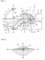
Fig. 1] Fig. 1 illustrates a first embodiment of a vehicle headlamp according to the present invention, and is a schematic cross-sectional view in the longitudinal direction (a schematic cross-sectional view in the vertical direction) of a lamp unit when a movable shade is located in a second position. - [
Fig. 2] Fig. 2 is a view for explaining a high-beam light distribution pattern radiated from a lamp unit when the movable shade is located in the second position. - [
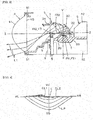
Fig. 3] Fig. 3 is a schematic cross-sectional view in the longitudinal direction of the lamp unit when the movable shade is located in a first position. - [
Fig. 4] Fig. 4 is a view for explaining a low-beam light distribution pattern (a light distribution pattern for passing) radiated by the lamp unit when the movable shade is located in the first position. - [
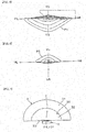
Fig. 5] Fig. 5 is a view for explaining a first light distribution pattern formed by a first reflection surface and a lens. - [
Fig. 6] Fig. 6 is a view for explaining a second light distribution pattern formed by a second reflection surface and a lens. - [
Fig. 7] Fig. 7 is a schematic front view illustrating a light source, and a first reflection surface and a second reflection surface of a reflector (a view along an arrow VII ofFig. 1 ). - [
Fig. 8] Fig. 8 is a schematic cross-sectional view in the longitudinal direction of a lamp unit illustrating a second embodiment of the vehicle headlamp according to the present invention. - Below, two examples of the embodiments (exemplary examples) of a vehicle headlamp according to the present invention will be described in detail with reference to the drawings. In
Fig. 1 ,Fig. 3 , andFig. 8 , a semiconductor light source, a projection lens, a movable shade, a solenoid of a switching device, and a power transmission member are not hatched. InFig. 2 , andFig. 4 toFig. 6 , the reference code "VU-VD" designates a vertical line from the top to the bottom of a screen. The reference code "HL-HR" designates a horizontal line from the left to the right of the screen. In each of the iso-intensity lines ofFig. 2 , andFig. 4 toFig. 6 , a central part is a light curve with high luminous intensity, and an outer part is a light curve of which luminous intensity decreases toward the outsides. In the specification and attached claims, the terms "front", "rear", "top", "bottom", "left" and "right" respectively designate the front, rear, top, bottom, left and right in when a vehicle headlamp according to the present invention is mounted on a vehicle. -
Fig. 1 to Fig. 7 illustrate the first embodiment of the vehicle headlamp according to the present invention. Below, a structure of a vehicle headlamp according to the first embodiment will be described. In this example, for example, a headlamp of a vehicle headlamp will be described. - In
Fig. 1 , thereference numeral 1 denotes a vehicle headlamp according to the first embodiment. Thevehicle headlamp 1 is provided on the left and right sides, respectively, at the front of a vehicle. As illustrated inFig. 1 , thevehicle headlamp 1 includes a lamp housing (not illustrated), a lamp lens (not illustrated), asemiconductor light source 2 as a light source, areflector 3, aprojection lens 4 as a lens, aheat sink member 5, amovable shade 6, asolenoid 7 of a switching mechanism, and apower transmission member 8. - The lamp housing and the lamp lens (e.g., a transparent outer lens) define a lamp chamber (not illustrated). The
semiconductor light source 2, thereflector 3, theprojection lens 4, theheat sink member 5, themovable shade 6, thesolenoid 7 and thepower transmission member 8 form a projector type lamp unit. Thelamp units - Note that, lamp units other than the
lamp units - For example, the
heat sink member 5 is formed by a material of high thermal conductivity, e.g., resin or metal die-casting (aluminum die-casting). Thesemiconductor light source 2, thereflector 3, theprojection lens 4, thesolenoid 7 and thepower transmission member 8 are attached to theheat sink member 5. Theheat sink member 5 functions both as a heat radiation member and as an attaching member. - The
heat sink member 5 includes aplanar part 50, aring part 51, and a plurality offin parts 52. Thesemiconductor light source 2, thereflector 3, thesolenoid 7, and thepower transmission member 8 are attached to theplanar part 50. Theprojection lens 4 is attached to thering part 51. Note that thering part 51 may be a separated member from theheat sink member 5 and may be attached to theheat sink member 5. - The
semiconductor light source 2 is, for example, a self-radiation semiconductor light source, such as an LED, an OEL, or an OLED (an organic EL). Thesemiconductor light source 2 is attached to theplanar part 50 of theheat sink member 5 via a holder (not illustrated) or a screw (not illustrated), for example. A current from a lightning circuit (not illustrated) is supplied to thesemiconductor light source 2. - The
semiconductor light source 2 includes a light-radiatingsurface 20 that radiates light. In this example, the light-radiatingsurface 20 faces upward and is rectangular in shape. The longitudinal direction of the light-radiatingsurface 20 orthogonality or substantially orthogonality crosses the left-right direction of a lens optical axis Z of theprojection lens 4. - The
reflector 3 is formed by, for example, a material of high thermal resistance and a non-light transmissive material, such as resin members. Thereflector 3 is attached to theplanar part 50 of theheat sink member 5 with a screw (not illustrated), and the like. - The
reflector 3 is hollow of which front part and lower part are open and rear part, upper part, and left and right parts are closed. Reflection surfaces 31 and 32 each formed as a free-form curved surface based on a spheroid are provided on the concave inner surface at the closed part of thereflector 3. The reflection surfaces 31 and 32 reflect light from the light-radiatingsurface 20 toward themovable shade 6 and theprojection lens 4. The reflection surfaces 31 and 32 are provided on the upper side of the lens optical axis Z in the spheroid with the lens optical axis Z as a rotation axis. - The light-radiating
surface 20 faces the reflection surfaces 31 and 32 in the up-down direction via the lens optical axis Z. That is, the light-radiatingsurface 20 is located below the lens optical axis Z. The reflection surfaces 31 and 32 are located on the upper side of the lens optical axis Z. - The reflection surfaces 31 and 32 are divided into the
first reflection surface 31 and thesecond reflection surface 32. Between thefirst reflection surface 31 and thesecond reflection surface 32, a steppedboundary part 30 is formed. Thefirst reflection surface 31 includes a first focal point F11 located at or near a center of the light-radiatingsurface 20, and a second focal point F12 located at or near a lens focal point F3 of thelens 4, and on theprojection lens 4 side with respect to the lens focal point F3. Thesecond reflection surface 32 includes a first focal point F21 located at or near a center of the light-radiatingsurface 20, and a second focal point F22 located on the light-radiatingsurface 20 side with respect to the lens focal point F3. - Each of the
first reflection surface 31 and thesecond reflection surface 32 is a free-form curved surface based on a spheroid. Therefore, strictly speaking, a plurality of first focal points F11 and F21 and a plurality of second focal points F12 and F22 exist, instead of a single F11, F21, F12, and F22 exist. However, since distances among the focal points are significantly short, each of a group of the focal points may be considered as a single focal point. - The
first reflection surface 31 is located on theprojection lens 4 side with respect to thesecond reflection surface 32. That is, thefirst reflection surface 31 is provided to extend from theboundary part 30 to the open front part of thereflector 3. Thesecond reflection surface 32 is provided to extend from theboundary part 30 to the closed rear part of thereflector 3. Theboundary part 30 is located on the rear side of the reflector 3 (on the opposite side of the projection lens 4) with respect to a vertical line V of the light-radiatingsurface 20. - The
second reflection surface 32 is concave outward (on the side opposite to the light-radiating surface 20) with respect to thefirst reflection surface 31. Therefore, the stepped surface of theboundary part 30 is not visible through theprojection lens 4 from the front side of the lamp unit. This avoids reflected light reflected on the stepped surface of theboundary part 30 penetrating through theprojection lens 4 and being radiated to the front. - The
first reflection surface 31 and thesecond reflection surface 32 make the light from the light-radiatingsurface 20 reflected to theprojection lens 4 side. Reflected light from thefirst reflection surface 31 converges onto the second focal point F12, is radiated from the second focal point F12 and is incident on theprojection lens 4. Reflected light from thesecond reflection surface 32 converges (crosses) onto the second focal point F22 and is radiated from the second focal point F22 and is incident on theprojection lens 4. - For example, the
projection lens 4 is a lens made of resin, such as PC, PMMA, and PCO. That is, the light radiated from the light-radiatingsurface 20 of thesemiconductor light source 2 does not have heat of high temperature, and a resin lens may be used as theprojection lens 4. Theprojection lens 4 is attached to thering part 51 of theheat sink member 5. Theprojection lens 4 may be attached to theheat sink member 5 using theheat sink member 5 and a separately provided holder instead of thering part 51. - The
projection lens 4 has the lens focal point (the rear-side lens focal point) F3, the lens optical axis Z, and a meridional image surface S which is a focal surface on the object space side is provided. The lens focal point F3 is located at an intersection of the lens optical axis Z and the meridional image surface S. Theprojection lens 4 is a projection lens based on an aspheric surface. Therefore, strictly speaking, a plurality of lens focal points F3, lens optical axes Z, and meridional image surfaces S exist, respectively instead of a single lens focal point F3, a single lens optical axis Z, and a single meridional image surface S exist. However, since distances among the focal points, among the optical axes, and among the image surfaces are significantly short, the focal points, the optical axes, and the image surfaces may be considered as a single focal point, a single optical axis, and a single image surface. - The
projection lens 4 is formed by anincident surface 40 on the rear side and aradiation surface 41 on the front side. Theincident surface 40 faces thereflector 3. Theincident surface 40 is formed as a planar surface or an aspheric substantially planar surface (convex or concave with respect to the reflector 3). Theradiation surface 41 is an aspheric convex surface. - Light from the light-radiating
surface 20, which is the reflected light from the reflection surfaces 31 and 32, is radiated through theprojection lens 4 to the outside, i.e., to the front of the vehicle as radiation light L1 and L2. That is, the reflected light from thefirst reflection surface 31 is radiated to the front through theprojection lens 4 as a first light distribution pattern P1 (seeFig. 5 ). The reflected light from thesecond reflection surface 32 is radiated to the front through theprojection lens 4 as the second light distribution pattern P2 (seeFig. 6 ) which partially overlaps a part of the first light distribution pattern P1. Therefore, a high-beam light distribution pattern HP illustrated inFig. 2 and a low-beam light distribution pattern LP illustrated inFig. 4 are radiated to the front of the vehicle through theprojection lens 4. - The first light distribution pattern P1 and the second light distribution pattern P2 radiated through the
projection lens 4 are the reflected light from thefirst reflection surface 31 and thesecond reflection surface 32, and are formed by an aggregate of a large number of projection images (not illustrated) of the light-radiatingsurface 20. The projection images of the first light distribution pattern P1 and the second light distribution pattern P2 are projection images inverted in the up-down direction and the left-right direction with respect to the lens optical axis Z and the lens focal point F3 when the projection images pass through the meridional image surface S. - Here, the second focal point F12 of the
first reflection surface 31 is located at or near the lens focal point F3, and on theprojection lens 4 side with respect to the lens focal point F3. The second focal point F22 of thesecond reflection surface 32 is located on the light-radiatingsurface 20 side with respect to the lens focal point F3. - Therefore, the reflected light from the first reflection surface 31 (a beam of light depicted by a solid arrow) passes through the meridional image surface S while converging onto the second focal point F12 as illustrated in
Fig. 1 andFig. 3 . Therefore, the distance between light beams of the reflected light from thefirst reflection surface 31 passing through the meridional image surface S increases toward upward with respect to the lens optical axis Z and the lens focal point F3. Therefore, in the first light distribution pattern P1 which is the reflected light from thefirst reflection surface 31 and is radiated through theprojection lens 4, the iso-intensity line is dense in the upper part and less dense in the lower part as illustrated inFig. 5 . - The reflected light from the second reflection surface 32 (a beam of light depicted by a solid arrow) converges (crosses) onto the second focal point F22 as illustrated in
Fig. 1 , and passes through the meridional image surface S while being radiated from the second focal point F22. Therefore, the distance between light beams of the reflected light from thesecond reflection surface 32 passing through the meridional image surface S increases toward downward with respect to the lens optical axis Z and the lens focal point F3 when the reflected light is inverted in the up-down direction from the reflected light from thefirst reflection surface 31. Therefore, in the second light distribution pattern P2 which is the reflected light from thesecond reflection surface 32 and is radiated through theprojection lens 4, the iso-intensity line is less dense in the upper part and dense in the lower part as illustrated inFig. 6 . - The upper part of the first light distribution pattern P1 in which the iso-intensity line is dense and the lower part of the second light distribution pattern P2 in which the iso-intensity line is dense overlap each other and form the high-beam light distribution pattern HP. The high-beam light distribution pattern HP includes a hot zone HZ at a center of the screen (the intersection of the vertical line from the top to the bottom of the screen (VU-VD) and the horizontal line from the left to the right of the screen (HL-HR)).
- The
solenoid 7 is attached to theplanar part 50 of theheat sink member 5 by a screw, for example (not illustrated). Thesolenoid 7 moves themovable shade 6 to a first position (a position illustrated inFig. 3 ) and a second position (a position illustrated inFig. 1 ) via a plunger (not illustrated) and thepower transmission member 8 and keeps at the moved position. - The
movable shade 6 is formed by a non-light transmissive member, and, in this example, a sheet metal. Themovable shade 6 is attached to the plunger of thesolenoid 7 via thepower transmission member 8. Themovable shade 6 is formed by press-drawing a sheet metal. Themovable shade 6 is disposed between thesemiconductor light source 2 and theprojection lens 4. - When the
movable shade 6 is located in the first position, all the reflected light from thesecond reflection surface 32 and a part of the reflected light from the first reflection surface 31 (a part surrounded by a two-dot chain line inFig. 5 ) are shielded (cutoff). Then, an unshielded remaining part of the reflected light from thefirst reflection surface 31 is made to be incident on theincident surface 40 of theprojection lens 4. Therefore, the low-beam light distribution pattern LP illustrated inFig. 4 is radiated to the front of the vehicle. The low-beam light distribution pattern LP has an upper-edge oblique cutoff line CL1, an upper-edge horizontal cutoff line CL2, and an elbow point E. - When the
movable shade 6 is located in the second position, all of the reflected light from thefirst reflection surface 31 and all of the reflected light from thesecond reflection surface 32 are made to be incident on theincident surface 40 of theprojection lens 4. This causes the high-beam light distribution pattern HP illustrated inFig. 2 to be radiated to the front of the vehicle. - The
power transmission member 8 is attached to themovable shade 6 and the plunger of thesolenoid 7. Thepower transmission member 8 includes a link member, a spring member, and the like. Thepower transmission member 8 transmits power of thesolenoid 7 to themovable shade 6. Note that thepower transmission member 8 and themovable shade 6 may be integrated with each other. - The
vehicle headlamp 1 according to the first embodiment has structures described above and, operations thereof will be described below. - The light-radiating
surface 20 of thesemiconductor light source 2 is turned on to radiate light. Then the light radiated from the up-faced light-radiatingsurface 20 is reflected on theprojection lens 4 side as the reflected light on thefirst reflection surface 31 and thesecond reflection surface 32 of thereflector 3. Here, when themovable shade 6 is driven by thesolenoid 7 and is located in the second position via thepower transmission member 8, all of the reflected light from thefirst reflection surface 31 and all of the reflected light from thesecond reflection surface 32 travel toward theprojection lens 4. The reflected light that has travelled toward theprojection lens 4 is incident on theprojection lens 4 from theincident surface 40 of theprojection lens 4 and is radiated to the front of the vehicle from theradiation surface 41 of theprojection lens 4 as the high-beam light distribution pattern HP (radiation light L1 and L2). - That is, the reflected light from the
first reflection surface 31 is radiated to the front as the first light distribution pattern P1 (radiation light L1). The reflected light from thesecond reflection surface 32 is radiated to the front as the second light distribution pattern P2 (radiation light L2). The upper part of the first light distribution pattern P1 and the lower part of the second light distribution pattern P2 overlap each other and form the high-beam light distribution pattern HP illustrated inFig. 2 . The high-beam light distribution pattern HP has the hot zone HZ at the center of the screen. - Here, driving of the
solenoid 7 is stopped, and themovable shade 6 is moved to the first position from the second position via thepower transmission member 8, and is kept in the first position. Then, all of the reflected light from thesecond reflection surface 32 not shielded by themovable shade 6 and a part of the reflected light from the first reflection surface 31 (the part surrounded by a two-dot chain line inFig. 5 ) is covered by themovable shade 6. Then, remaining part of the reflected light from thefirst reflection surface 31 that is not shielded by themovable shade 6 located in the first position travels toward theprojection lens 4. The reflected light that has travelled toward theprojection lens 4 is incident on theprojection lens 4 from theincident surface 40 of theprojection lens 4 and is radiated to the front of the vehicle from theradiation surface 41 of theprojection lens 4 as the low-beam light distribution pattern LP (radiation light L1). - The
vehicle headlamp 1 according to the first embodiment has the structures and operations described above and, effects thereof will be described below. - The
vehicle headlamp 1 according to the first embodiment can provide a vehicle headlamp that provides a high-beam light distribution pattern HP having a hot zone HZ at the center of a screen. Below, detailed description will be given. - The
vehicle headlamp 1 according to the first embodiment is a projector type vehicle headlamp. Therefore, the projection images of the first light distribution pattern P1 and the second light distribution pattern P2 radiated through the projection lens 4 (the projection images of the light-radiating surface 20) are the reflected light from thefirst reflection surface 31 and thesecond reflection surface 32, and are projection images inverted in the up-down direction and the left-right direction with respect to the lens optical axis Z and the lens focal point F3 when the projection images pass through the meridional image surface S. - Also, in the
vehicle headlamp 1 according to the first embodiment, the second focal point F12 of thefirst reflection surface 31 is located at or near the lens focal point F3 and on theprojection lens 4 side with respect to the lens focal point F3. Therefore, the reflected light from the first reflection surface 31 (a beam of light depicted by a solid arrow) passes through the meridional image surface S while converging onto the second focal point F12 as illustrated inFig. 1 andFig. 3 . Therefore, the distance between light beams of the reflected light from thefirst reflection surface 31 passing through the meridional image surface S increases toward upward with respect to the lens optical axis Z and the lens focal point F3. Therefore, in the first light distribution pattern P1 which is the reflected light from thefirst reflection surface 31 and is radiated through theprojection lens 4, the iso-intensity line is dense in the upper part and less dense in the lower part as illustrated inFig. 5 . - In the
vehicle headlamp 1 according to the first embodiment, the second focal point F22 of thesecond reflection surface 32 is located on the light-radiatingsurface 20 side with respect to the lens focal point F3. Therefore, the reflected light from the second reflection surface 32 (a beam of light depicted by a solid arrow) passes through the meridional image surface S while converging (crossing) onto the second focal point F22 and radiating from the second focal point F22 as illustrated inFig. 1 . Therefore, the distance between light beams of the reflected light from thesecond reflection surface 32 passing through the meridional image surface S increases toward downward with respect to the lens optical axis Z and the lens focal point F3 when the reflected light is inverted in the up-down direction from the reflected light from thefirst reflection surface 31. Therefore, in the second light distribution pattern P2 which is the reflected light from thesecond reflection surface 32 and is radiated through theprojection lens 4, the iso-intensity line is less dense in the upper part and dense in the lower part as illustrated inFig. 6 . - As a result, in the
vehicle headlamp 1 according to the first embodiment, the upper part of the first light distribution pattern P1 in which the iso-intensity line is dense and the lower part of the second light distribution pattern P2 in which the iso-intensity line is dense overlap each other. Therefore, thevehicle headlamp 1 according to the first embodiment can provide a high-beam light distribution pattern HP having a hot zone HZ at the center of a screen. - Here, the
vehicle headlamp 1 according to the first embodiment will be compared with a vehicle headlamp of general projector type to which the present invention is not applied. As in thevehicle headlamp 1 according to the first embodiment, a vehicle headlamp of general projector type has an up-faced light-radiating surface, and a reflection surface located on an upper side of a lens optical axis in a spheroid with the lens optical axis being a rotation axis. For this reason, it is difficult to dispose a vehicle headlamp of general projector type to be arrange a light distribution pattern above the horizontal line HL-HR of the screen. - In contrast, in the
vehicle headlamp 1 according to the first embodiment, the reflection surface is divided into thefirst reflection surface 31 and thesecond reflection surface 32, and the second focal point F22 of thesecond reflection surface 32 is located on the light-radiatingsurface 20 side with respect to the lens focal point F3. Therefore, in thevehicle headlamp 1 according to the first embodiment, as described above, dense/less-dense in the iso-intensity line in the first light distribution pattern P1 in the up-down direction and dense/less-dense in the iso-intensity line in the second light distribution pattern P2 in the up-down direction are inverted in the up-down direction. Then, the upper part of the first light distribution pattern P1 in which the iso-intensity line is dense and the lower part of the second light distribution pattern P2 in which the iso-intensity line is dense overlap each other. Therefore, thevehicle headlamp 1 according to the first embodiment can reliably and easily provide a high-beam light distribution pattern HP having a hot zone HZ at the center of a screen. - In the
vehicle headlamp 1 according to the first embodiment, the light-radiatingsurface 20 faces the reflection surfaces 31 and 32 via the lens optical axis Z. That is, in thevehicle headlamp 1 according to the first embodiment, the light-radiatingsurface 20 is located on the lower side of the optical axis Z. Therefore, in thevehicle headlamp 1 according to the first embodiment, as compared with a vehicle headlamp in which a light-radiating surface is located at substantially the same position as the lens optical axis, reflected light that is reflected from thesecond reflection surface 32 and cannot be incident on theprojection lens 4 can be reduced, and reflected light that can be incident on theprojection lens 4 can be increased. - That is, as illustrated in
Fig. 1 , the reflected light from thesecond reflection surface 32 passes through the meridional image surface S and is incident on theprojection lens 4 while converging (crossing) onto the second focal point F22 and radiating from the second focal point F22. At this time, of the reflected light that is reflected from thesecond reflection surface 32 and is radiated from the second focal point F22, reflected light separated from the lens optical axis Z (reflected light below the lens optical axis Z) may not be able to enter theprojection lens 4. Also, a lower part of the reflected light of the reflected light radiated from the second focal point F22 is separated downward from the lens optical axis Z as the light-radiatingsurface 20 approaches the lens focal point F3. Therefore, an amount of the reflected light that cannot be incident on theprojection lens 4 increases. On the other hand, a lower part of the reflected light of the reflected light radiated from the second focal point F22 approaches the lens optical axis Z and is located on the upper side of the lens optical axis Z as the light-radiatingsurface 20 is separated from the lens focal point F3 and is located on the lower side of the lens focal point F3. Therefore, an amount of the reflected light that can be incident on theprojection lens 4 increases. - As described above, in the
vehicle headlamp 1 in the first embodiment, the light-radiatingsurface 20 is located on the lower side of the lens optical axis Z. Therefore, as compared with a vehicle headlamp in which a light-radiating surface is located at substantially the same position as the lens optical axis, reflected light that is reflected from thesecond reflection surface 32 and cannot be incident on theprojection lens 4 can be reduced, and reflected light that can be incident on theprojection lens 4 can be increased. - Also, in the
vehicle headlamp 1 according to the first embodiment, the reflected light that cannot be incident on theprojection lens 4 is reflected light that forms a lower part of the reflected light that passes through the meridional image surface S and an upper part of the second light distribution pattern P2 in which the iso-intensity line is less dense. On the other hand, in thevehicle headlamp 1 according to the first embodiment, the reflected light that can be incident on theprojection lens 4 is reflected light that forms an upper part of the reflected light that passes through the meridional image surface S and a lower part in which the iso-intensity line is dense in the second light distribution pattern P2. Therefore, in thevehicle headlamp 1 according to the first embodiment, the reflected light that forms the upper part of which the iso-intensity line is less dense in the second light distribution pattern P2 cannot be incident on theprojection lens 4, but the reflected light that forms the lower part of which the iso-intensity line is dense in the second light distribution pattern P2 can be incident on theprojection lens 4. Therefore, in thevehicle headlamp 1 according to the first embodiment, the light from the light-radiatingsurface 20, which is the reflected light from thesecond reflection surface 32 can be used effectively. - The
vehicle headlamp 1 according to the first embodiment includes themovable shade 6, thesolenoid 7, and thepower transmission member 8. Therefore, in thevehicle headlamp 1 according to the first embodiment, the high-beam light distribution pattern HP and the low-beam light distribution pattern LP can be switchably radiated to the front of the vehicle. - In the
vehicle headlamp 1 according to the first embodiment, theboundary part 30 between thefirst reflection surface 31 and thesecond reflection surface 32 is located on the rear side of thereflector 3, i.e., on the opposite side of theprojection lens 4 with respect to the vertical line V of the light-radiatingsurface 20, and on the near side of thesecond reflection surface 32. Therefore, thevehicle headlamp 1 according to the first embodiment can adjust an area of thefirst reflection surface 31 to be wide. Therefore, an amount of light of the low-beam light distribution pattern LP can be adjusted to be significantly large. Note that, in thevehicle headlamp 1 according to the first embodiment, by adjusting the position of theboundary part 30 and adjusting an area of thefirst reflection surface 31 and an area of thesecond reflection surface 32, an amount of light of the second light distribution pattern P2 of the high-beam light distribution pattern HP and an amount of light of the low-beam light distribution pattern LP can be adjusted. - In the
vehicle headlamp 1 according to the first embodiment, thesecond reflection surface 32 is concave outward with respect to thefirst reflection surface 31, i.e., concave on the side opposite to the light-radiatingsurface 20. Therefore, in thevehicle headlamp 1 according to the first embodiment, the stepped surface of theboundary part 30 is not visible through theprojection lens 4 from the front side of the lamp unit. This avoids, in thevehicle headlamp 1 according to the first embodiment, penetrating reflected light reflected on the stepped surface of theboundary part 30 through theprojection lens 4 and being radiated to the front. -
Fig. 8 illustrates a second embodiment of the vehicle headlamp according to the present invention. InFig. 8 , the same reference numerals as those inFig. 1 to Fig. 7 each designate the same part. Below, structures, operations, and effects of thevehicle headlamp 100 of the second embodiment will be described. - The
vehicle headlamp 1 according to the first embodiment includes themovable shade 6, thesolenoid 7, and thepower transmission member 8, and in which the high-beam light distribution pattern HP and the low-beam light distribution pattern LP are switchably radiated to the front of a vehicle. In contrast, thevehicle headlamp 100 according to the second embodiment does not include amovable shade 6, asolenoid 7, and apower transmission member 8, and radiates only the high-beam light distribution pattern HP to the front of a vehicle. - In the
vehicle headlamp 100 according to the second embodiment, in a reflector 300, aboundary part 30 between afirst reflection surface 31 and asecond reflection surface 32 is located on the front side of thereflector 3 with respect to the vertical line V of a light-radiatingsurface 20, i.e., on the near side of theprojection lens 4. Therefore, in thevehicle headlamp 100 according to the second embodiment, an area of thesecond reflection surface 32 can be adjusted to be wide. Therefore, an amount of light of a second light distribution pattern P2 of a high-beam light distribution pattern HP can be adjusted to be large. Note that, in thevehicle headlamp 100 according to the second embodiment, by adjusting the position of theboundary part 30 and adjusting an area of thefirst reflection surface 31 and an area of thesecond reflection surface 32, an amount of light of the second light distribution pattern P2 of the high-beam light distribution pattern HP and an amount of light of a low-beam light distribution pattern LP can be adjusted. - In the
vehicle headlamp 100 according to the second embodiment, thesecond reflection surface 32 is convex inward with respect to thefirst reflection surface 31, i.e., convex on the light-radiatingsurface 20 side. Therefore, in thevehicle headlamp 100 according to the second embodiment, light from the light-radiatingsurface 20, which is reflected light reflected on theboundary part 30, can be effectively used for the formation of the high-beam light distribution pattern HP. - Note that, in the first and the second embodiments, the
first reflection surface 31 and thesecond reflection surface 32 are formed by a single segment. In the present invention, however, thefirst reflection surface 31 and thesecond reflection surface 32 may be formed by a plurality of segments. - Note that the present invention is not limited by the first and the second embodiments described above.
-
- 1, 100 Vehicle headlamp
- 2 Semiconductor light source
- 20 Light-radiating surface
- 3, 300 Reflector
- 30 Boundary part
- 31 First reflection surface
- 32 Second reflection surface
- 4 Projection lens
- 40 Incident surface
- 41 Radiation surface
- 5 Heat sink member
- 50 Planar part
- 51 Ring part
- 52 Fin part
- 6 Movable shade
- 7 Solenoid
- 8 Power transmission member
- CL1 Oblique cutoff line
- CL2 Horizontal cutoff line
- E Elbow point
- F11, F21 First focal point
- F12, F22 Second focal point
- F3 Lens focal point
- HL-HR Horizontal line
- HP High-beam light distribution pattern
- HZ Hot zone
- LP Low-beam light distribution pattern
- P1 First light distribution pattern
- P2 Second light distribution pattern
- S Meridional image surface
- V Vertical line
- VU-VD Vertical line from top to bottom
- Z Lens optical axis
Claims (5)
- A vehicle headlamp, comprising:a light source having a light-radiating surface that radiates light;a reflector having a reflection surface that reflects the light from the light-radiating surface; anda lens having a lens focal point, whereinthe reflection surface is a reflection surface based on a spheroid and is divided into a first reflection surface and a second reflection surface,the first reflection surface includes a first focal point located on or near the light-radiating surface and a second focal point located on or near the lens focus,the second reflection surface includes a first focal point located on or near the light-radiating surface and a second focal point located on the light-radiating surface side with respect to the lens focal point, andthe lens radiates reflected light from the first reflection surface the front through the lens as a first light distribution pattern, and radiates reflected light from the second reflection surface to the front through the lens as a second light distribution pattern partially overlapping a part of the first light distribution pattern.
- The vehicle headlamp according to claim 1, wherein
the lens has a lens optical axis, and
the light-radiating surface faces the first reflection surface and the second reflection surface via the lens optical axis. - The vehicle headlamp according to claim 1, wherein
the first reflection surface is located on the lens side with respect to the second reflection surface, and
a boundary part between the first reflection surface and the second reflection surface is located on the lens side with respect to the vertical line of the light-radiating surface. - The vehicle headlamp according to claim 1, wherein
the second reflection surface is convex toward the light-radiating surface with respect to the first reflection surface. - The vehicle headlamp according to claim 1, further comprising
a movable shade arranged between the lens and the light-radiating surface, the first reflection surface and the second reflection surface, and
a switching mechanism configured to switch the movable shade between a first position and a second position, wherein
when located in the first position, the movable shade shields a part of the reflected light from the first reflection surface and the reflected light from the second reflection surface and causes a remaining part of the reflected light from the first reflection surface to be incident on the lens and,
when located in the second position, the movable shade, the movable shade causes the reflected light from the first reflection surface and the reflected light from the second reflection surface to be incident on the lens.
Applications Claiming Priority (2)
| Application Number | Priority Date | Filing Date | Title |
|---|---|---|---|
| JP2015219810A JP6651797B2 (en) | 2015-11-09 | 2015-11-09 | Vehicle headlights |
| PCT/JP2016/083295 WO2017082322A1 (en) | 2015-11-09 | 2016-11-09 | Vehicle headlamp |
Publications (3)
| Publication Number | Publication Date |
|---|---|
| EP3376093A1 true EP3376093A1 (en) | 2018-09-19 |
| EP3376093A4 EP3376093A4 (en) | 2019-07-10 |
| EP3376093B1 EP3376093B1 (en) | 2021-05-05 |
Family
ID=58695449
Family Applications (1)
| Application Number | Title | Priority Date | Filing Date |
|---|---|---|---|
| EP16864283.3A Active EP3376093B1 (en) | 2015-11-09 | 2016-11-09 | Vehicle headlamp |
Country Status (5)
| Country | Link |
|---|---|
| US (1) | US10495280B2 (en) |
| EP (1) | EP3376093B1 (en) |
| JP (1) | JP6651797B2 (en) |
| CN (1) | CN108243618B (en) |
| WO (1) | WO2017082322A1 (en) |
Families Citing this family (7)
| Publication number | Priority date | Publication date | Assignee | Title |
|---|---|---|---|---|
| JP6889609B2 (en) * | 2017-05-24 | 2021-06-18 | 株式会社小糸製作所 | Vehicle lighting |
| KR102392310B1 (en) * | 2017-07-24 | 2022-05-02 | 현대모비스 주식회사 | Illumination device foe vehicle |
| JP6992337B2 (en) * | 2017-09-11 | 2022-02-03 | 市光工業株式会社 | Vehicle lighting |
| US11454366B2 (en) | 2017-11-21 | 2022-09-27 | Hasco Vision Technology Co., Ltd. | Automobile lamp lighting system, automobile lamp assembly and automobile |
| CN109681843A (en) * | 2019-02-26 | 2019-04-26 | 华域视觉科技(上海)有限公司 | Car light mould group and the automobile for applying it |
| WO2021025136A1 (en) * | 2019-08-08 | 2021-02-11 | 株式会社小糸製作所 | Vehicle lamp |
| EP3961088A1 (en) * | 2020-08-28 | 2022-03-02 | ZKW Group GmbH | Motor vehicle headlamp |
Family Cites Families (17)
| Publication number | Priority date | Publication date | Assignee | Title |
|---|---|---|---|---|
| JP2517368B2 (en) * | 1988-09-27 | 1996-07-24 | 株式会社小糸製作所 | Vehicle headlight and vehicle headlight device |
| JP4335785B2 (en) * | 2004-02-27 | 2009-09-30 | スタンレー電気株式会社 | Vehicle lighting |
| JP4498977B2 (en) * | 2005-05-18 | 2010-07-07 | 株式会社小糸製作所 | Vehicle headlamp |
| JP4729441B2 (en) * | 2006-06-09 | 2011-07-20 | スタンレー電気株式会社 | Vehicle lighting |
| JP4694438B2 (en) * | 2006-08-01 | 2011-06-08 | スタンレー電気株式会社 | Vehicle headlamp |
| JP5321048B2 (en) * | 2008-12-26 | 2013-10-23 | 市光工業株式会社 | Vehicle headlamp |
| JP2011090839A (en) * | 2009-10-21 | 2011-05-06 | Koito Mfg Co Ltd | Vehicular headlamp |
| JP5396254B2 (en) * | 2009-12-07 | 2014-01-22 | スタンレー電気株式会社 | Vehicle headlamp |
| JP5501878B2 (en) * | 2010-07-08 | 2014-05-28 | 株式会社小糸製作所 | Lamp unit |
| JP5526452B2 (en) * | 2010-09-10 | 2014-06-18 | スタンレー電気株式会社 | Vehicle lamp unit |
| JP5425129B2 (en) * | 2011-03-18 | 2014-02-26 | スタンレー電気株式会社 | Vehicle headlamp |
| JP5716576B2 (en) * | 2011-06-30 | 2015-05-13 | スタンレー電気株式会社 | Vehicle lamp unit |
| JP6180709B2 (en) * | 2012-06-28 | 2017-08-16 | 株式会社小糸製作所 | Lamp unit |
| JP6154169B2 (en) * | 2013-03-29 | 2017-06-28 | 株式会社小糸製作所 | Vehicle headlamp |
| JP6248525B2 (en) * | 2013-10-08 | 2017-12-20 | 市光工業株式会社 | Lighting fixtures for vehicles |
| JP6266332B2 (en) | 2013-12-17 | 2018-01-24 | 株式会社小糸製作所 | Vehicle lighting |
| JP6102878B2 (en) * | 2014-10-02 | 2017-03-29 | マツダ株式会社 | Vehicle headlamp |
-
2015
- 2015-11-09 JP JP2015219810A patent/JP6651797B2/en active Active
-
2016
- 2016-11-09 CN CN201680064683.4A patent/CN108243618B/en active Active
- 2016-11-09 WO PCT/JP2016/083295 patent/WO2017082322A1/en not_active Ceased
- 2016-11-09 US US15/774,437 patent/US10495280B2/en active Active
- 2016-11-09 EP EP16864283.3A patent/EP3376093B1/en active Active
Also Published As
| Publication number | Publication date |
|---|---|
| JP6651797B2 (en) | 2020-02-19 |
| JP2017091780A (en) | 2017-05-25 |
| CN108243618B (en) | 2021-02-05 |
| EP3376093B1 (en) | 2021-05-05 |
| WO2017082322A1 (en) | 2017-05-18 |
| US20180328560A1 (en) | 2018-11-15 |
| US10495280B2 (en) | 2019-12-03 |
| CN108243618A (en) | 2018-07-03 |
| EP3376093A4 (en) | 2019-07-10 |
Similar Documents
| Publication | Publication Date | Title |
|---|---|---|
| EP3376093B1 (en) | Vehicle headlamp | |
| CN104075208B (en) | Vehicular headlamp | |
| US20070041207A1 (en) | Vehicle lamp | |
| EP2407710B1 (en) | Vehicle lamp | |
| US9366405B2 (en) | Headlamp system for motor vehicles | |
| JP6197303B2 (en) | Vehicle lighting | |
| EP2484964B1 (en) | Lamp unit | |
| US9644810B2 (en) | Lamp unit | |
| CN207080934U (en) | Car lighting | |
| JP2014075271A (en) | Vehicular lighting fixture | |
| CN108375048A (en) | On-vehicle lamp | |
| JP6248525B2 (en) | Lighting fixtures for vehicles | |
| JP4863502B2 (en) | Vehicle headlamp | |
| JP2011025820A (en) | Vehicular lighting fixture | |
| EP2226555A2 (en) | Vehicular headlamp | |
| US10502379B2 (en) | Vehicle lighting fixture | |
| JP5338742B2 (en) | Vehicle headlamp | |
| JP6266332B2 (en) | Vehicle lighting | |
| JP5962366B2 (en) | Vehicle lighting | |
| EP2309176A2 (en) | Vehicle headlamp | |
| JP6443676B2 (en) | LIGHTING DEVICE AND MOBILE BODY HAVING LIGHTING DEVICE | |
| JP6464678B2 (en) | Vehicle headlamp | |
| JP2019040677A (en) | Vehicle headlamp | |
| JP2016170880A (en) | Luminaire and movable body including luminaire | |
| US20090316415A1 (en) | Lamp unit |
Legal Events
| Date | Code | Title | Description |
|---|---|---|---|
| STAA | Information on the status of an ep patent application or granted ep patent |
Free format text: STATUS: THE INTERNATIONAL PUBLICATION HAS BEEN MADE |
|
| PUAI | Public reference made under article 153(3) epc to a published international application that has entered the european phase |
Free format text: ORIGINAL CODE: 0009012 |
|
| STAA | Information on the status of an ep patent application or granted ep patent |
Free format text: STATUS: REQUEST FOR EXAMINATION WAS MADE |
|
| 17P | Request for examination filed |
Effective date: 20180509 |
|
| AK | Designated contracting states |
Kind code of ref document: A1 Designated state(s): AL AT BE BG CH CY CZ DE DK EE ES FI FR GB GR HR HU IE IS IT LI LT LU LV MC MK MT NL NO PL PT RO RS SE SI SK SM TR |
|
| AX | Request for extension of the european patent |
Extension state: BA ME |
|
| DAV | Request for validation of the european patent (deleted) | ||
| DAX | Request for extension of the european patent (deleted) | ||
| A4 | Supplementary search report drawn up and despatched |
Effective date: 20190606 |
|
| RIC1 | Information provided on ipc code assigned before grant |
Ipc: F21S 41/255 20180101ALI20190531BHEP Ipc: F21S 41/148 20180101ALI20190531BHEP Ipc: F21Y 115/10 20160101AFI20190531BHEP Ipc: F21S 41/147 20180101ALI20190531BHEP Ipc: F21Y 115/15 20160101ALI20190531BHEP Ipc: F21S 41/686 20180101ALI20190531BHEP Ipc: F21S 41/33 20180101ALI20190531BHEP |
|
| REG | Reference to a national code |
Ref country code: DE Ref legal event code: R079 Ref document number: 602016057576 Country of ref document: DE Free format text: PREVIOUS MAIN CLASS: F21S0008120000 Ipc: F21Y0115100000 |
|
| RIC1 | Information provided on ipc code assigned before grant |
Ipc: F21S 41/255 20180101ALI20201104BHEP Ipc: F21S 41/147 20180101ALI20201104BHEP Ipc: F21S 41/686 20180101ALI20201104BHEP Ipc: F21S 41/33 20180101ALI20201104BHEP Ipc: F21S 41/148 20180101ALI20201104BHEP Ipc: F21Y 115/15 20160101ALI20201104BHEP Ipc: F21Y 115/10 20160101AFI20201104BHEP |
|
| GRAP | Despatch of communication of intention to grant a patent |
Free format text: ORIGINAL CODE: EPIDOSNIGR1 |
|
| STAA | Information on the status of an ep patent application or granted ep patent |
Free format text: STATUS: GRANT OF PATENT IS INTENDED |
|
| INTG | Intention to grant announced |
Effective date: 20201211 |
|
| RIN1 | Information on inventor provided before grant (corrected) |
Inventor name: SUZUKI EIJI |
|
| GRAS | Grant fee paid |
Free format text: ORIGINAL CODE: EPIDOSNIGR3 |
|
| GRAA | (expected) grant |
Free format text: ORIGINAL CODE: 0009210 |
|
| STAA | Information on the status of an ep patent application or granted ep patent |
Free format text: STATUS: THE PATENT HAS BEEN GRANTED |
|
| AK | Designated contracting states |
Kind code of ref document: B1 Designated state(s): AL AT BE BG CH CY CZ DE DK EE ES FI FR GB GR HR HU IE IS IT LI LT LU LV MC MK MT NL NO PL PT RO RS SE SI SK SM TR |
|
| REG | Reference to a national code |
Ref country code: GB Ref legal event code: FG4D |
|
| REG | Reference to a national code |
Ref country code: CH Ref legal event code: EP |
|
| REG | Reference to a national code |
Ref country code: AT Ref legal event code: REF Ref document number: 1390266 Country of ref document: AT Kind code of ref document: T Effective date: 20210515 |
|
| REG | Reference to a national code |
Ref country code: IE Ref legal event code: FG4D |
|
| REG | Reference to a national code |
Ref country code: DE Ref legal event code: R096 Ref document number: 602016057576 Country of ref document: DE |
|
| REG | Reference to a national code |
Ref country code: LT Ref legal event code: MG9D |
|
| REG | Reference to a national code |
Ref country code: AT Ref legal event code: MK05 Ref document number: 1390266 Country of ref document: AT Kind code of ref document: T Effective date: 20210505 |
|
| PG25 | Lapsed in a contracting state [announced via postgrant information from national office to epo] |
Ref country code: FI Free format text: LAPSE BECAUSE OF FAILURE TO SUBMIT A TRANSLATION OF THE DESCRIPTION OR TO PAY THE FEE WITHIN THE PRESCRIBED TIME-LIMIT Effective date: 20210505 Ref country code: LT Free format text: LAPSE BECAUSE OF FAILURE TO SUBMIT A TRANSLATION OF THE DESCRIPTION OR TO PAY THE FEE WITHIN THE PRESCRIBED TIME-LIMIT Effective date: 20210505 Ref country code: AT Free format text: LAPSE BECAUSE OF FAILURE TO SUBMIT A TRANSLATION OF THE DESCRIPTION OR TO PAY THE FEE WITHIN THE PRESCRIBED TIME-LIMIT Effective date: 20210505 Ref country code: BG Free format text: LAPSE BECAUSE OF FAILURE TO SUBMIT A TRANSLATION OF THE DESCRIPTION OR TO PAY THE FEE WITHIN THE PRESCRIBED TIME-LIMIT Effective date: 20210805 Ref country code: HR Free format text: LAPSE BECAUSE OF FAILURE TO SUBMIT A TRANSLATION OF THE DESCRIPTION OR TO PAY THE FEE WITHIN THE PRESCRIBED TIME-LIMIT Effective date: 20210505 |
|
| PG25 | Lapsed in a contracting state [announced via postgrant information from national office to epo] |
Ref country code: LV Free format text: LAPSE BECAUSE OF FAILURE TO SUBMIT A TRANSLATION OF THE DESCRIPTION OR TO PAY THE FEE WITHIN THE PRESCRIBED TIME-LIMIT Effective date: 20210505 Ref country code: GR Free format text: LAPSE BECAUSE OF FAILURE TO SUBMIT A TRANSLATION OF THE DESCRIPTION OR TO PAY THE FEE WITHIN THE PRESCRIBED TIME-LIMIT Effective date: 20210806 Ref country code: IS Free format text: LAPSE BECAUSE OF FAILURE TO SUBMIT A TRANSLATION OF THE DESCRIPTION OR TO PAY THE FEE WITHIN THE PRESCRIBED TIME-LIMIT Effective date: 20210905 Ref country code: PL Free format text: LAPSE BECAUSE OF FAILURE TO SUBMIT A TRANSLATION OF THE DESCRIPTION OR TO PAY THE FEE WITHIN THE PRESCRIBED TIME-LIMIT Effective date: 20210505 Ref country code: NO Free format text: LAPSE BECAUSE OF FAILURE TO SUBMIT A TRANSLATION OF THE DESCRIPTION OR TO PAY THE FEE WITHIN THE PRESCRIBED TIME-LIMIT Effective date: 20210805 Ref country code: PT Free format text: LAPSE BECAUSE OF FAILURE TO SUBMIT A TRANSLATION OF THE DESCRIPTION OR TO PAY THE FEE WITHIN THE PRESCRIBED TIME-LIMIT Effective date: 20210906 Ref country code: RS Free format text: LAPSE BECAUSE OF FAILURE TO SUBMIT A TRANSLATION OF THE DESCRIPTION OR TO PAY THE FEE WITHIN THE PRESCRIBED TIME-LIMIT Effective date: 20210505 Ref country code: SE Free format text: LAPSE BECAUSE OF FAILURE TO SUBMIT A TRANSLATION OF THE DESCRIPTION OR TO PAY THE FEE WITHIN THE PRESCRIBED TIME-LIMIT Effective date: 20210505 |
|
| REG | Reference to a national code |
Ref country code: NL Ref legal event code: MP Effective date: 20210505 |
|
| PG25 | Lapsed in a contracting state [announced via postgrant information from national office to epo] |
Ref country code: NL Free format text: LAPSE BECAUSE OF FAILURE TO SUBMIT A TRANSLATION OF THE DESCRIPTION OR TO PAY THE FEE WITHIN THE PRESCRIBED TIME-LIMIT Effective date: 20210505 |
|
| PG25 | Lapsed in a contracting state [announced via postgrant information from national office to epo] |
Ref country code: EE Free format text: LAPSE BECAUSE OF FAILURE TO SUBMIT A TRANSLATION OF THE DESCRIPTION OR TO PAY THE FEE WITHIN THE PRESCRIBED TIME-LIMIT Effective date: 20210505 Ref country code: DK Free format text: LAPSE BECAUSE OF FAILURE TO SUBMIT A TRANSLATION OF THE DESCRIPTION OR TO PAY THE FEE WITHIN THE PRESCRIBED TIME-LIMIT Effective date: 20210505 Ref country code: CZ Free format text: LAPSE BECAUSE OF FAILURE TO SUBMIT A TRANSLATION OF THE DESCRIPTION OR TO PAY THE FEE WITHIN THE PRESCRIBED TIME-LIMIT Effective date: 20210505 Ref country code: RO Free format text: LAPSE BECAUSE OF FAILURE TO SUBMIT A TRANSLATION OF THE DESCRIPTION OR TO PAY THE FEE WITHIN THE PRESCRIBED TIME-LIMIT Effective date: 20210505 Ref country code: ES Free format text: LAPSE BECAUSE OF FAILURE TO SUBMIT A TRANSLATION OF THE DESCRIPTION OR TO PAY THE FEE WITHIN THE PRESCRIBED TIME-LIMIT Effective date: 20210505 Ref country code: SK Free format text: LAPSE BECAUSE OF FAILURE TO SUBMIT A TRANSLATION OF THE DESCRIPTION OR TO PAY THE FEE WITHIN THE PRESCRIBED TIME-LIMIT Effective date: 20210505 Ref country code: SM Free format text: LAPSE BECAUSE OF FAILURE TO SUBMIT A TRANSLATION OF THE DESCRIPTION OR TO PAY THE FEE WITHIN THE PRESCRIBED TIME-LIMIT Effective date: 20210505 |
|
| REG | Reference to a national code |
Ref country code: DE Ref legal event code: R097 Ref document number: 602016057576 Country of ref document: DE |
|
| PLBE | No opposition filed within time limit |
Free format text: ORIGINAL CODE: 0009261 |
|
| STAA | Information on the status of an ep patent application or granted ep patent |
Free format text: STATUS: NO OPPOSITION FILED WITHIN TIME LIMIT |
|
| 26N | No opposition filed |
Effective date: 20220208 |
|
| PG25 | Lapsed in a contracting state [announced via postgrant information from national office to epo] |
Ref country code: IS Free format text: LAPSE BECAUSE OF FAILURE TO SUBMIT A TRANSLATION OF THE DESCRIPTION OR TO PAY THE FEE WITHIN THE PRESCRIBED TIME-LIMIT Effective date: 20210905 Ref country code: AL Free format text: LAPSE BECAUSE OF FAILURE TO SUBMIT A TRANSLATION OF THE DESCRIPTION OR TO PAY THE FEE WITHIN THE PRESCRIBED TIME-LIMIT Effective date: 20210505 |
|
| PG25 | Lapsed in a contracting state [announced via postgrant information from national office to epo] |
Ref country code: MC Free format text: LAPSE BECAUSE OF FAILURE TO SUBMIT A TRANSLATION OF THE DESCRIPTION OR TO PAY THE FEE WITHIN THE PRESCRIBED TIME-LIMIT Effective date: 20210505 |
|
| REG | Reference to a national code |
Ref country code: CH Ref legal event code: PL |
|
| PG25 | Lapsed in a contracting state [announced via postgrant information from national office to epo] |
Ref country code: LU Free format text: LAPSE BECAUSE OF NON-PAYMENT OF DUE FEES Effective date: 20211109 Ref country code: IT Free format text: LAPSE BECAUSE OF FAILURE TO SUBMIT A TRANSLATION OF THE DESCRIPTION OR TO PAY THE FEE WITHIN THE PRESCRIBED TIME-LIMIT Effective date: 20210505 Ref country code: BE Free format text: LAPSE BECAUSE OF NON-PAYMENT OF DUE FEES Effective date: 20211130 |
|
| REG | Reference to a national code |
Ref country code: BE Ref legal event code: MM Effective date: 20211130 |
|
| PG25 | Lapsed in a contracting state [announced via postgrant information from national office to epo] |
Ref country code: LI Free format text: LAPSE BECAUSE OF NON-PAYMENT OF DUE FEES Effective date: 20211130 Ref country code: CH Free format text: LAPSE BECAUSE OF NON-PAYMENT OF DUE FEES Effective date: 20211130 |
|
| PG25 | Lapsed in a contracting state [announced via postgrant information from national office to epo] |
Ref country code: IE Free format text: LAPSE BECAUSE OF NON-PAYMENT OF DUE FEES Effective date: 20211109 |
|
| PGFP | Annual fee paid to national office [announced via postgrant information from national office to epo] |
Ref country code: GB Payment date: 20221125 Year of fee payment: 7 |
|
| PG25 | Lapsed in a contracting state [announced via postgrant information from national office to epo] |
Ref country code: HU Free format text: LAPSE BECAUSE OF FAILURE TO SUBMIT A TRANSLATION OF THE DESCRIPTION OR TO PAY THE FEE WITHIN THE PRESCRIBED TIME-LIMIT; INVALID AB INITIO Effective date: 20161109 |
|
| PG25 | Lapsed in a contracting state [announced via postgrant information from national office to epo] |
Ref country code: CY Free format text: LAPSE BECAUSE OF FAILURE TO SUBMIT A TRANSLATION OF THE DESCRIPTION OR TO PAY THE FEE WITHIN THE PRESCRIBED TIME-LIMIT Effective date: 20210505 |
|
| PG25 | Lapsed in a contracting state [announced via postgrant information from national office to epo] |
Ref country code: MK Free format text: LAPSE BECAUSE OF FAILURE TO SUBMIT A TRANSLATION OF THE DESCRIPTION OR TO PAY THE FEE WITHIN THE PRESCRIBED TIME-LIMIT Effective date: 20210505 |
|
| PG25 | Lapsed in a contracting state [announced via postgrant information from national office to epo] |
Ref country code: TR Free format text: LAPSE BECAUSE OF FAILURE TO SUBMIT A TRANSLATION OF THE DESCRIPTION OR TO PAY THE FEE WITHIN THE PRESCRIBED TIME-LIMIT Effective date: 20210505 |
|
| GBPC | Gb: european patent ceased through non-payment of renewal fee |
Effective date: 20231109 |
|
| PG25 | Lapsed in a contracting state [announced via postgrant information from national office to epo] |
Ref country code: MT Free format text: LAPSE BECAUSE OF FAILURE TO SUBMIT A TRANSLATION OF THE DESCRIPTION OR TO PAY THE FEE WITHIN THE PRESCRIBED TIME-LIMIT Effective date: 20210505 |
|
| PG25 | Lapsed in a contracting state [announced via postgrant information from national office to epo] |
Ref country code: GB Free format text: LAPSE BECAUSE OF NON-PAYMENT OF DUE FEES Effective date: 20231109 |
|
| PG25 | Lapsed in a contracting state [announced via postgrant information from national office to epo] |
Ref country code: GB Free format text: LAPSE BECAUSE OF NON-PAYMENT OF DUE FEES Effective date: 20231109 |
|
| PGFP | Annual fee paid to national office [announced via postgrant information from national office to epo] |
Ref country code: DE Payment date: 20251119 Year of fee payment: 10 |
|
| PGFP | Annual fee paid to national office [announced via postgrant information from national office to epo] |
Ref country code: FR Payment date: 20251126 Year of fee payment: 10 |