EP3376039B1 - Groupe pompe centrifuge - Google Patents
Groupe pompe centrifuge Download PDFInfo
- Publication number
- EP3376039B1 EP3376039B1 EP17160841.7A EP17160841A EP3376039B1 EP 3376039 B1 EP3376039 B1 EP 3376039B1 EP 17160841 A EP17160841 A EP 17160841A EP 3376039 B1 EP3376039 B1 EP 3376039B1
- Authority
- EP
- European Patent Office
- Prior art keywords
- valve element
- centrifugal pump
- pump assembly
- assembly according
- impeller
- Prior art date
- Legal status (The legal status is an assumption and is not a legal conclusion. Google has not performed a legal analysis and makes no representation as to the accuracy of the status listed.)
- Active
Links
- XLYOFNOQVPJJNP-UHFFFAOYSA-N water Substances O XLYOFNOQVPJJNP-UHFFFAOYSA-N 0.000 claims description 19
- 239000012530 fluid Substances 0.000 claims description 16
- 239000000314 lubricant Substances 0.000 claims description 11
- 230000033001 locomotion Effects 0.000 claims description 10
- 239000002245 particle Substances 0.000 claims description 3
- 230000005484 gravity Effects 0.000 claims description 2
- 230000008878 coupling Effects 0.000 description 30
- 238000010168 coupling process Methods 0.000 description 30
- 238000005859 coupling reaction Methods 0.000 description 30
- 238000010438 heat treatment Methods 0.000 description 30
- 239000007788 liquid Substances 0.000 description 22
- 230000013011 mating Effects 0.000 description 10
- 230000008901 benefit Effects 0.000 description 5
- 238000007789 sealing Methods 0.000 description 5
- 230000001276 controlling effect Effects 0.000 description 3
- 239000012535 impurity Substances 0.000 description 3
- 230000000149 penetrating effect Effects 0.000 description 3
- 230000002829 reductive effect Effects 0.000 description 3
- 238000004378 air conditioning Methods 0.000 description 2
- 238000011109 contamination Methods 0.000 description 2
- 238000006073 displacement reaction Methods 0.000 description 2
- 230000007774 longterm Effects 0.000 description 2
- 238000005461 lubrication Methods 0.000 description 2
- 239000000203 mixture Substances 0.000 description 2
- 230000000284 resting effect Effects 0.000 description 2
- 230000001133 acceleration Effects 0.000 description 1
- 230000005540 biological transmission Effects 0.000 description 1
- 230000008859 change Effects 0.000 description 1
- 239000000356 contaminant Substances 0.000 description 1
- 230000001419 dependent effect Effects 0.000 description 1
- 230000000694 effects Effects 0.000 description 1
- 230000002349 favourable effect Effects 0.000 description 1
- 210000003746 feather Anatomy 0.000 description 1
- 239000004519 grease Substances 0.000 description 1
- 238000007373 indentation Methods 0.000 description 1
- 230000007246 mechanism Effects 0.000 description 1
- 230000036961 partial effect Effects 0.000 description 1
- 230000001105 regulatory effect Effects 0.000 description 1
- 230000000717 retained effect Effects 0.000 description 1
- 230000002441 reversible effect Effects 0.000 description 1
Images


Classifications
-
- F—MECHANICAL ENGINEERING; LIGHTING; HEATING; WEAPONS; BLASTING
- F04—POSITIVE - DISPLACEMENT MACHINES FOR LIQUIDS; PUMPS FOR LIQUIDS OR ELASTIC FLUIDS
- F04D—NON-POSITIVE-DISPLACEMENT PUMPS
- F04D1/00—Radial-flow pumps, e.g. centrifugal pumps; Helico-centrifugal pumps
-
- F—MECHANICAL ENGINEERING; LIGHTING; HEATING; WEAPONS; BLASTING
- F04—POSITIVE - DISPLACEMENT MACHINES FOR LIQUIDS; PUMPS FOR LIQUIDS OR ELASTIC FLUIDS
- F04D—NON-POSITIVE-DISPLACEMENT PUMPS
- F04D13/00—Pumping installations or systems
- F04D13/02—Units comprising pumps and their driving means
- F04D13/021—Units comprising pumps and their driving means containing a coupling
-
- F—MECHANICAL ENGINEERING; LIGHTING; HEATING; WEAPONS; BLASTING
- F04—POSITIVE - DISPLACEMENT MACHINES FOR LIQUIDS; PUMPS FOR LIQUIDS OR ELASTIC FLUIDS
- F04D—NON-POSITIVE-DISPLACEMENT PUMPS
- F04D13/00—Pumping installations or systems
- F04D13/02—Units comprising pumps and their driving means
- F04D13/06—Units comprising pumps and their driving means the pump being electrically driven
- F04D13/0686—Mechanical details of the pump control unit
-
- F—MECHANICAL ENGINEERING; LIGHTING; HEATING; WEAPONS; BLASTING
- F04—POSITIVE - DISPLACEMENT MACHINES FOR LIQUIDS; PUMPS FOR LIQUIDS OR ELASTIC FLUIDS
- F04D—NON-POSITIVE-DISPLACEMENT PUMPS
- F04D15/00—Control, e.g. regulation, of pumps, pumping installations or systems
- F04D15/0005—Control, e.g. regulation, of pumps, pumping installations or systems by using valves
- F04D15/0016—Control, e.g. regulation, of pumps, pumping installations or systems by using valves mixing-reversing- or deviation valves
-
- F—MECHANICAL ENGINEERING; LIGHTING; HEATING; WEAPONS; BLASTING
- F04—POSITIVE - DISPLACEMENT MACHINES FOR LIQUIDS; PUMPS FOR LIQUIDS OR ELASTIC FLUIDS
- F04D—NON-POSITIVE-DISPLACEMENT PUMPS
- F04D15/00—Control, e.g. regulation, of pumps, pumping installations or systems
- F04D15/0005—Control, e.g. regulation, of pumps, pumping installations or systems by using valves
- F04D15/0022—Control, e.g. regulation, of pumps, pumping installations or systems by using valves throttling valves or valves varying the pump inlet opening or the outlet opening
-
- F—MECHANICAL ENGINEERING; LIGHTING; HEATING; WEAPONS; BLASTING
- F04—POSITIVE - DISPLACEMENT MACHINES FOR LIQUIDS; PUMPS FOR LIQUIDS OR ELASTIC FLUIDS
- F04D—NON-POSITIVE-DISPLACEMENT PUMPS
- F04D15/00—Control, e.g. regulation, of pumps, pumping installations or systems
- F04D15/0066—Control, e.g. regulation, of pumps, pumping installations or systems by changing the speed, e.g. of the driving engine
-
- F—MECHANICAL ENGINEERING; LIGHTING; HEATING; WEAPONS; BLASTING
- F04—POSITIVE - DISPLACEMENT MACHINES FOR LIQUIDS; PUMPS FOR LIQUIDS OR ELASTIC FLUIDS
- F04D—NON-POSITIVE-DISPLACEMENT PUMPS
- F04D29/00—Details, component parts, or accessories
- F04D29/04—Shafts or bearings, or assemblies thereof
- F04D29/046—Bearings
-
- F—MECHANICAL ENGINEERING; LIGHTING; HEATING; WEAPONS; BLASTING
- F04—POSITIVE - DISPLACEMENT MACHINES FOR LIQUIDS; PUMPS FOR LIQUIDS OR ELASTIC FLUIDS
- F04D—NON-POSITIVE-DISPLACEMENT PUMPS
- F04D29/00—Details, component parts, or accessories
- F04D29/08—Sealings
- F04D29/086—Sealings especially adapted for liquid pumps
-
- F—MECHANICAL ENGINEERING; LIGHTING; HEATING; WEAPONS; BLASTING
- F04—POSITIVE - DISPLACEMENT MACHINES FOR LIQUIDS; PUMPS FOR LIQUIDS OR ELASTIC FLUIDS
- F04D—NON-POSITIVE-DISPLACEMENT PUMPS
- F04D29/00—Details, component parts, or accessories
- F04D29/08—Sealings
- F04D29/10—Shaft sealings
- F04D29/106—Shaft sealings especially adapted for liquid pumps
-
- F—MECHANICAL ENGINEERING; LIGHTING; HEATING; WEAPONS; BLASTING
- F04—POSITIVE - DISPLACEMENT MACHINES FOR LIQUIDS; PUMPS FOR LIQUIDS OR ELASTIC FLUIDS
- F04D—NON-POSITIVE-DISPLACEMENT PUMPS
- F04D29/00—Details, component parts, or accessories
- F04D29/40—Casings; Connections of working fluid
- F04D29/42—Casings; Connections of working fluid for radial or helico-centrifugal pumps
- F04D29/426—Casings; Connections of working fluid for radial or helico-centrifugal pumps especially adapted for liquid pumps
- F04D29/4293—Details of fluid inlet or outlet
-
- F—MECHANICAL ENGINEERING; LIGHTING; HEATING; WEAPONS; BLASTING
- F04—POSITIVE - DISPLACEMENT MACHINES FOR LIQUIDS; PUMPS FOR LIQUIDS OR ELASTIC FLUIDS
- F04D—NON-POSITIVE-DISPLACEMENT PUMPS
- F04D29/00—Details, component parts, or accessories
- F04D29/40—Casings; Connections of working fluid
- F04D29/42—Casings; Connections of working fluid for radial or helico-centrifugal pumps
- F04D29/44—Fluid-guiding means, e.g. diffusers
- F04D29/46—Fluid-guiding means, e.g. diffusers adjustable
- F04D29/48—Fluid-guiding means, e.g. diffusers adjustable for unidirectional fluid flow in reversible pumps
- F04D29/486—Fluid-guiding means, e.g. diffusers adjustable for unidirectional fluid flow in reversible pumps especially adapted for liquid pumps
Definitions
- the invention relates to a centrifugal pump unit with an electric drive motor, an impeller driven by this and a rotatable valve element integrated into the centrifugal pump unit.
- Centrifugal pump units which have a movable, in particular pivotable valve element in the pump housing in order to selectively direct the liquid flow conveyed by the centrifugal pump unit into two different pressure-side flow paths, in particular depending on the direction of rotation of the drive motor.
- Arrangements are also known in which a switching device between two suction-side flow paths is integrated into the centrifugal pump unit.
- Such an arrangement is, for example, off DE 90 139 92 U1 famous.
- This known switching device has an inflow element located on the pressure side of the impeller which, depending on the direction of rotation, switches the valve device on the suction side. This requires a relatively complex mechanism.
- a similar device is out U.S. 5,924,432 known, which shows a direction of rotation movable valve element inside a pump housing. This valve element is rotatably mounted on a screw inside the pump housing.
- the centrifugal pump assembly has an electric drive motor, by means of which at least one impeller can be driven in rotation.
- the impeller is rotatably connected to the magnet rotor of the drive motor, either directly or z. B. over a wave.
- the drive motor is preferably designed as a wet-running electric drive motor, d. H. it preferably has a can or a can between the stator and rotor, so that the rotor rotates in the liquid to be conveyed by the impeller.
- the impeller is arranged in a pump housing which defines the flow paths to and from the impeller.
- a valve element is also arranged, which is rotatable between at least two switching positions. This can, for example, be a valve element of a switchover valve or mixing valve, as will be described below.
- the valve element is rotatably held on a bearing in the interior of the pump housing.
- the storage of the valve element in the interior of the pump housing avoids shaft seals in the pump housing, which would be necessary if the bearing were arranged outside the pump housing.
- the bearing is arranged in a storage space which is separated by at least one seal from the rest of the interior space of the pump housing, which receives a fluid to be pumped or a liquid to be pumped.
- the pump unit is preferably designed for water as the fluid to be conveyed. So the centrifugal pump unit is suitable for. B. for use as a circulation pump in a heating and / or air conditioning system.
- the seal of the storage room compared to the interior of the pump housing has the advantage that impurities in the fluid to be conveyed are essentially kept away from the storage. At the same time, however, no absolutely hermetic seal is required, which would be required if the bearing were arranged outside the pump housing. According to the invention, a certain amount of leakage is tolerated in the bearing. Nevertheless, liquid cannot escape to the outside of the pump housing. Because impurities are kept away from the bearing, a smooth mounting of the valve element can be ensured. The smooth mounting is advantageous if the valve element is to be moved by the drive motor without an additional drive, in particular by hydraulic coupling via the fluid to be conveyed.
- the storage space can preferably be formed in one piece with the valve element.
- at least one section of a wall which delimits the storage space is formed in one piece with at least one wall of the valve element.
- the storage space is particularly preferably formed by an indentation on a wall of the valve element, in particular an end face of the valve element.
- the storage space preferably has a tubular or blind hole shape.
- the at least one bearing in the interior of the storage space can be lubricated by a lubricant, preferably at the factory.
- the lubricant can be, for example, a grease or another suitable lubricant.
- the lubricant is preferably introduced at the factory, ie the lubricant is already arranged in the storage room when the centrifugal pump unit is delivered. Since the seal of the storage room is not absolutely tight, but allows a certain amount of the liquid to be pumped through, it is possible to that in the course of time the lubricant is diluted and replaced by the liquid to be pumped or the fluid to be pumped during operation of the centrifugal pump unit.
- the bearing is preferably designed in such a way that the fluid to be conveyed or the liquid to be conveyed can serve as a lubricant.
- the bearing is particularly preferably designed as a slide bearing. This enables a very simple storage structure. Furthermore, such a bearing can also be lubricated by the liquid to be conveyed.
- the seal is not completely tight for that fluid or the liquid which the centrifugal pump assembly is designed to convey.
- the fluid to be conveyed is preferably water, so that the seal is adjusted accordingly so that it allows a certain amount of liquid or water to pass through.
- This has the advantage that the seal can be made simpler and, moreover, the friction in the area of the seal can be reduced.
- permanent lubrication of the bearing can advantageously be ensured if the penetrating liquid, in particular the penetrating water, takes on the function of a lubricant over time.
- the seal is advantageously designed in such a way that it retains particles located in the fluid to be conveyed by the impeller. In this way, impurities are kept away from the bearing, so that the ease of movement of the at least one bearing in the storage room is ensured in the long term.
- the storage space can be designed in such a way that it is only open on one side to the interior of the pump housing, so that a seal is arranged on only one side of the bearing. It is however, it is also conceivable that the storage space is designed in such a way that a seal is arranged on each of two sides of the bearing, which seal seals the storage space in the manner described from the rest of the interior of the pump housing.
- the at least one bearing is particularly preferably arranged centrally on the valve element. That is, the bearing centrally surrounds the axis of rotation of the valve element. This has the advantage that the bearing can be made very small in diameter, so that the friction in the bearing is reduced.
- the valve element preferably projects in the radial direction over the bearing, so that in this area there are favorable lever ratios for rotating the valve element about the at least one bearing.
- the diameter of the bearing is preferably less than a quarter of the diameter of the valve element.
- the at least one bearing is located in an area of the pump housing located on the suction side of the impeller. This means that at least one bearing is located in the area of the pump housing through which the liquid sucked in by the impeller flows. This has the advantage that the mounting of the valve element does not collide with the impeller and the drive motor.
- the at least one valve element is mechanically, magnetically and / or hydraulically coupled to the drive motor for its movement between the switching positions.
- a coupling can be provided between the drive motor and the valve element, for example between a rotor shaft or the impeller on one side and the valve element on the other.
- the clutch can be designed to be non-positive and / or frictional. More preferably, the coupling can be releasable so that it can be brought out of engagement in a targeted manner. This can be done, for example, depending on the speed of the Drive motor and / or the pressure in the pressure side area of the pump housing happen.
- the valve element can also be moved between the switching positions in a targeted manner by the drive motor, without a separate drive for the valve element being required.
- the drive motor is hydraulically coupled to the valve element, this hydraulic coupling preferably takes place via the fluid set in motion by the impeller.
- the fluid or the liquid in the pump housing can be set in a rotary movement by the impeller, which is transmitted to the valve element by friction, so that the valve element is rotated by the flow and can thus be moved between the switching positions.
- the drive motor and thus the impeller can preferably be driven in two opposite directions of rotation, so that the rotating flow in the pump housing also optionally runs in different directions of rotation.
- the hydraulic coupling has the advantage that it can easily disengage due to slippage. That is, when the valve element reaches a predetermined switching position and is fixed in this position, the flow can continue in the pump housing without moving the valve element any further. The flow then causes friction on the surface of the valve element, which, however, essentially corresponds to the usual hydraulic friction on the inside of the pump housing.
- the axis of rotation of the valve element is aligned with the axis of rotation of the drive motor.
- At least one force generating means can be present which exerts a force on the at least one valve element in the direction of one of the at least two switching positions, the force preferably being a spring force, a magnetic force and / or the force of gravity.
- the valve element can be automatically moved back into a starting position, which preferably corresponds to one of the switching positions, by the force generating means when the drive motor is switched off. That is, in this embodiment, no reversal of the direction of rotation of the drive motor is required in order to move the valve element back into its starting position.
- the valve element can be moved from the starting position into the other switching position due to a coupling with the drive motor by its rotation.
- a second clutch in order to keep the valve element in the starting position when the drive motor is in operation, a second clutch can be provided which fixes the valve element in this position, in particular with a friction fit.
- This coupling can, for example, be pressed into a coupled and thus holding position by the pressure in the interior of the pump housing, which is caused by the impeller.
- the drive motor is preferably provided with a control device which makes it possible to regulate the speed and / or acceleration of the drive motor.
- the drive motor is accelerated very quickly, this can lead to a pressure building up very quickly in the pump chamber, which can be used to quickly engage a coupling that fixes the valve element before the valve element is in the other switch position is moved. In this way, the valve element can be held in its starting position. If, on the other hand, the drive motor is accelerated slowly, a rotating flow can develop in the pump housing before the pressure is so high that the valve element is fixed. The valve element can then be moved into the other switching position by the flow.
- the at least one bearing preferably allows an axial movement of the valve element between a first and a second position.
- This configuration makes it possible to move the valve element axially to make it z. B. in the second position in a sealing and holding system with the pump housing or a contact surface connected to the pump housing.
- the valve element can then, for example, bear against at least one valve seat in a sealing manner.
- the system can take over the function of the above-described second coupling for fixing the valve element.
- the valve element is preferably spaced from the contact surfaces so that it can preferably rotate freely about the at least one bearing.
- the first position and / or the second position are preferably limited by a stop, with at least one of the stops preferably being located within the storage space.
- the stop can be formed, for example, by a contact surface in which the valve element comes to rest.
- a second stop is preferably provided in the opposite direction so that the valve element cannot move further than a predetermined amount away from the contact surface or the pump housing.
- At least one restoring element in particular a restoring spring, is also preferably provided, which exerts a restoring force on the valve element in the axial direction.
- the restoring element is preferably arranged in such a way that it moves the valve element into a position in which it is spaced from an abutment and / or sealing surface and is freely rotatable about the at least one bearing.
- the valve element is preferably pressed against the restoring element by a pressure force generated in the pump housing.
- the valve element preferably has a pressure surface, which is a pressure chamber facing inside the pump housing and on which the liquid pressure generated by the impeller inside the pump housing acts. If the force generated by the restoring element is exceeded by this pressure force, the valve element moves against the restoring element into a holding and / or sealing position, as has been described above.
- the restoring element is preferably arranged within the storage space. It is protected from contamination by the at least one seal.
- the valve element is arranged in the pump housing in such a way that it separates a suction chamber connected to a suction side of the impeller from a pressure chamber connected to the pressure side of the impeller.
- the differential pressure between suction chamber and pressure chamber can be used to press the valve element against a sealing or contact surface, on the one hand to seal the suction side against the pressure side and on the other hand to seal valve openings in the desired manner.
- a coupling can be created which fixes the valve element in a desired switching position when it rests on the contact surface.
- the valve element facing the pressure chamber, the valve element preferably has a pressure surface in the manner described, on which the pressure on the output side of the impeller acts.
- the centrifugal pump assembly further preferably has two alternative flow paths, the at least one valve element being arranged in these flow paths in such a way that the flow paths are opened differently in the at least two switching positions.
- the valve element can be designed as a pure switchover valve in such a way that in a first switching position it opens a first flow path and closes a second flow path and vice versa in one second switching position closes the first flow path and opens the second flow path.
- a valve element in the context of this invention is also to be understood as a coupled arrangement of two valve elements which are moved coupled with one another.
- the valve element can provide a mixing function in that it can, for example, also assume intermediate positions between the two switching positions described, in which both flow paths are open to a certain extent.
- valve element By shifting the valve element in these intermediate positions, the flow paths can be opened to different degrees, so that a mixing ratio of the flows through the two flow paths can be changed.
- the valve element is preferably designed and arranged in such a way that, when it moves, it opens one of the flow paths by the same amount by which the other flow path is closed at the same time.
- the two flow paths are particularly preferably located on the suction side of the impeller. That is, depending on the position of the valve element, the impeller sucks in from one of the two flow paths or from both flow paths, whereby the mixture of the flows from the two flow paths can then be changed by shifting the valve element.
- the valve element can also be located on the pressure side of the impeller or cause it to switch the flow between two pressure-side flow paths or, if configured as a mixing valve, mix it.
- centrifugal pump assembly according to the invention described in the following description relate to applications in heating and / or air conditioning systems in which a liquid heat transfer medium, in particular water, is circulated by the centrifugal pump assembly.
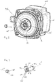
- the centrifugal pump unit has a motor housing 2 in which an electric drive motor is arranged.
- This has, in a known manner, a stator 4 and a rotor 6 which is arranged on a rotor shaft 8.
- the rotor 6 rotates in a rotor space which is separated from the stator space in which the stator 4 is arranged by a can or a can 10. This means that it is a wet-running electric drive motor.
- the motor housing 2 is connected to a pump housing 12, in which an impeller 14 that is non-rotatably connected to the rotor shaft 8 rotates.
- an electronics housing 16 is arranged, which contains control electronics or control device 17 for controlling the electric drive motor in the pump housing 2.
- the electronics housing 16 could also be arranged in a corresponding manner on another side of the stator housing 2.
- a movable valve element 18 is also arranged in the pump housing 12.
- This valve element 18 is rotatably mounted on an axis 20 in the interior of the pump housing 12, namely so that the axis of rotation of the valve element 18 is aligned with the axis of rotation X of the impeller 14.
- the axis 20 is fixed in a rotationally fixed manner on the bottom of the pump housing 12.
- the valve element 18 is not only rotatable about the axis 20, but can also be moved to a certain extent in the longitudinal direction X. This linear mobility is limited in one direction by the pump housing 12, against which the valve element 18 strikes with its outer circumference.
- the valve element 18 separates a suction chamber 24 from a pressure chamber 26 in the pump housing 12.
- the impeller 14 rotates in the pressure chamber 26.
- the pressure chamber 26 is connected to the pressure connection or pressure port 27 of the centrifugal pump unit, which forms the outlet of the centrifugal pump unit.
- a mechanical coupling is provided between the drive motor and the valve element, and in these embodiments the drive motor can be controlled by the control device 17 in two different operating modes or operating modes.
- a first operating mode which corresponds to normal operation of the circulating pump assembly
- the drive motor rotates in a conventional manner at a desired speed, in particular adjustable by the control device 17.
- the second operating mode the drive motor is controlled in open-loop mode, so that the rotor can be rotated step by step in individual angular steps specified by the control device 17, which are smaller than 360 °.
- the drive motor can thus be moved in individual steps in the manner of a stepping motor, which is used in these exemplary embodiments to move the valve element into a defined position in a targeted manner in small angular steps, as will be described below.
- a mixing valve is integrated in the pump housing 2, as can be used, for example, to set the temperature for underfloor heating.
- the motor housing 2 with the electronics housing 16 corresponds to the configuration described above.
- the pump housing 12 has two suction-side connections 32 and 34 which open into inlets 28 and 30 at the bottom of the pump housing 12, which are located in a plane transverse to the axis of rotation X.
- the valve element 18 is drum-shaped and consists of a cup-shaped lower part 76 which is closed by a cover 78 on its side facing the impeller 14.
- a suction opening 36 is formed in the central region of the cover 78.
- the suction opening 36 is in engagement with the suction mouth 38 of the impeller 14.
- the valve element 18 is rotatably mounted on a shaft 20 which is arranged in the bottom of the pump housing 12.
- the axis of rotation of the valve element 18 corresponds to the axis of rotation X of the rotor shaft 8.
- the valve element 18 is also axially displaceable along the axis X and is moved by a spring 48 into the position shown in FIG Fig.
- the rest position shown is pressed, in which the valve element 18 is in a released position in which the lower part 76 does not lie against the bottom of the pump housing 12, so that the valve element 18 is essentially freely rotatable about the axis 20.
- the coupling 108 engages with a mating coupling 110 which is arranged non-rotatably on the valve element 18.
- the coupling 108 has beveled coupling surfaces which essentially describe a sawtooth profile along a circumferential line in such a way that torque transmission from the coupling 108 to the mating coupling 110 is only possible in one direction of rotation is, namely in the direction of rotation A in Fig. 3 .
- the clutch slips, causing the valve element 18 to move axially.
- the direction of rotation B is that direction of rotation in which the pump unit is driven in normal operation.
- the direction of rotation A is used for the targeted adjustment of the valve element 18. This means that a coupling that is dependent on the direction of rotation is formed here.
- the mating clutch 110 disengages from the clutch 108 due to the pressure in the pressure chamber 26. If the pressure in the pressure chamber 26 increases, a pressure force acts on the cover 78 which opposes and exceeds the spring force of the spring 48, so that the valve element 18 is pressed into the adjacent position, which in Fig. 4 is shown. In this, the lower part 76 rests against the bottom side of the pump housing 12, so that on the one hand the valve element 18 is held in a force-locking manner and on the other hand a tight contact is achieved which seals the pressure and suction sides from one another in the manner described below.
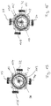
- the suction connection 32 opens out at the inlet 28 and the suction connection 34 opens out at the inlet 30 in the bottom of the pump housing 12 in the interior thereof, that is to say in the suction space 24.
- the lower part 76 of the valve element 18 has in its bottom an arcuate opening 112 which extends essentially over 90 °.
- Fig. 6 shows a first switching position in which the opening 112 only covers the inlet 30, so that a flow path is only given from the suction connection 34 to the suction opening 36 and thus to the suction mouth 38 of the impeller 14.
- the second inlet 28 is tightly closed by the base of the valve element 18 resting in its circumferential area.
- Fig. 8 shows the second switching position in which the opening 112 only covers the inlet 28, while the inlet 30 is closed.
- FIG. 7 now shows an intermediate position in which the opening 112 covers both inlets 28 and 30, the inlet 30 being only partially released.
- a mixing ratio between the flows from the inlets 28 and 30 can be changed.
- the valve element 18 can also be adjusted in small steps in order to change the mixing ratio.
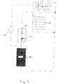
- the centrifugal pump unit with the integrated valve is indicated by the dashed line 1.
- the hydraulic circuit has a heat source 114 in the form of, for example, a gas boiler, the outlet of which opens into, for example, the suction connection 34 of the pump housing 12.
- an underfloor heating circuit 116 connects to the pressure connection 27 of the centrifugal pump unit 1, the return of which is connected both to the inlet of the heat source 114 and to the suction connection 32 of the centrifugal pump unit.
- a further heating circuit 120 can be supplied with a heat transfer medium, which has the temperature of the heat source 114 on the outlet side, via a second circulating pump assembly 118.
- the flow temperature of the underfloor heating circuit 116 can be regulated in such a way that cold water from the return is mixed with the hot water on the outlet side of the heat source 114, with the mixing ratio being changed by changing the opening ratios of the inlets 28 and 30 in the manner described above Rotation of the valve element 18h can be changed.
- the second embodiment according to Figures 10 to 19 shows a centrifugal pump unit which, in addition to the mixer functionality described above, also has a switchover functionality for has additional supply of a secondary heat exchanger for domestic water heating.
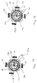
- valve element 18i has, in addition to the opening 112, a through-channel 122 which extends from an opening 124 in the cover 78i to an opening in the bottom of the lower part 76i and thus connects the two axial ends of the valve element 18i with one another. Furthermore, an arcuate bridging opening 126 is formed in the valve element 18i only to the underside, that is to say to the bottom of the lower part 76i and thus to the suction chamber 24, which is closed to the pressure chamber 26 by the cover 78i.
- the pump housing 12 has a further connection 128.
- the connection 128 opens into an inlet 130 in the bottom of the circulation pump assembly 12 in addition to the inlets 28 and 30 into the suction chamber 24.
- the cover 78i of the valve element 18i being shown partially open in these figures in order to clarify the position of the openings below.
- Fig. 15 shows a first switching position in which the opening 112 is opposite the inlet 30, so that a flow connection is established from the suction connection 34 to the suction mouth 38 of the impeller 14. In the switch position according to Fig.
- the opening 112 lies above the inlet 130, so that a flow connection is created from the connection 128 to the suction opening 36 and via this into the suction mouth 38 of the impeller 14.
- the opening 112 lies above the inlet 30, so that in turn a flow connection from the suction connection 34 is given to the suction mouth 38 of the impeller 14.
- the bridging opening 126 simultaneously covers the input 130 and part of the input 28, so that a connection is also created from the connection 128 via the input 130, the bridging opening 126 and the input 28 to the connection 32.
- Fig. 18 shows a fourth switching position in which the through-channel 122 completely covers the inlet 28, so that the connection 32 is connected to the pressure chamber 26 via the through-channel 122 and the opening 124. At the same time, the bridging opening 126 only covers the input 130. The opening 112 continues to cover the input 30.
- Such a centrifugal pump unit can, for example, be used in a heating system as shown in Fig. 19 is shown to find use. There, the dashed line delimits the centrifugal pump unit 1, as it is based on the Figures 10 to 18 has been described.
- the heating system in turn has a primary heat exchanger or a heat source 114, which can be a gas boiler, for example.
- a first heating circuit 120 which can be formed, for example, by conventional heating elements or radiators.
- a flow path branches off to a secondary heat exchanger 56 for heating domestic water.
- the heating system also has an underfloor heating circuit 116.
- the returns of the heating circuit 120 and the underfloor heating circuit 116 open into the suction connection 34 on the pump housing 12.
- the return from the secondary heat exchanger 56 opens into the connection 128, which, as will be described below, offers two functionalities.
- the connection 32 of the pump housing 12 is connected to the flow of the underfloor heating circuit 116.
- the impeller 14 conveys liquid from the suction connection 34 via the pressure connection 27 through the heat source 140 and the heating circuit 120 and back to the suction connection 34. If the valve element 18i is in the second switching position, which is shown in FIG Fig. 16 is shown, the system is switched to domestic water operation, in this state the pump unit or the impeller 14 pumps liquid from the connection 128, which serves as a suction connection, through the pressure connection 27, via the heat source 114 through the secondary heat exchanger 56 and back to the connection 128. If the valve element 18i is in the third switching position, which is shown in Fig. 17 is shown, the underfloor heating circuit 116 is also supplied.
- the water flows through the suction connection 34 into the suction mouth 38 of the impeller 14 and is conveyed through the first heating circuit 120 via the pressure connection 27 via the heat source 114 in the manner described.
- the liquid exits the pressure chamber 26 into the opening 124 and through the passage 122 and thus flows to the connection 32 and via this into the underfloor heating circuit 116.
- Fig. 17 The switching position shown flows simultaneously via the bridging opening 126 via the connection 128 and the inlet 130 into the connection 32. That is, here water flows via the heat source 114 through the secondary heat exchanger 26 and the connection 128 to the connection 32 Secondary heat exchanger 56, if essentially no heat is removed, hot water is added to the connection 32 in addition to the cold water which flows from the pressure chamber 26 via the through-channel 122 to the connection 32.
- Fig. 18 shows a switching position in which the admixture is switched off and the connection 32 is only in direct connection with the pressure chamber 26.
- the rotor 6 is preferably first positioned in such a way that the control device 17 moves the rotor 6 by controlling the stator 4 accordingly, it does not rotate all the way into the stored angular position, but rather preferably stops shortly before.
- the rotor 6 is rotated into a previously stored angular position or in an angular position which is slightly before the last angular position stored in the direction of rotation.
- the rotor can then be rotated together with the valve element 18, 18i into a desired second angular position, the control device 17 controlling the stator 6 in such a way that the rotor 6 rotates precisely by the desired angle in this second operating mode.
- the mating coupling 110 is taken along via the coupling 108, so that the valve element 18, 18i is then rotated into the desired angular position.
- the rotor 6 is stopped and the control device 17 switches back to the first operating mode or the first operating mode and starts the rotor 6 in the opposite direction of rotation, so that the clutch 108 can disengage from the mating clutch 110 and otherwise through the axial Displacement of the valve element 18, 18i due to the pressure generated in the pressure chamber 26, the clutch 108 and the mating clutch 110 completely disengage and the valve element 18, 18i is held in the switch position reached by resting on the bottom of the pump housing 12.
- the coupling 108 has two bevels or wedge surfaces 132 which extend starting from two end edges 134 which run essentially in a diametrical direction with respect to the axis of rotation X.
- engagement surfaces 136 extend, which essentially run in a plane which is spanned by the axis of rotation X and a diameter line to this axis of rotation X.
- the mating coupling 110 has a web-shaped projection 138 extending in the diameter direction with respect to the axis of rotation X, which protrudes in the axial direction and has two substantially parallel side surfaces, which in turn extend in planes which in the Essentially spanned by the diameter line and the axis of rotation X or axes parallel to these.
- the side surfaces of the projection 138 abut the engagement surfaces 136 when the clutch is engaged.
- the projection 138 slides on the wedge surfaces 137 with axial displacement.
- this embodiment of the coupling 108 and the mating coupling 110 there are exactly two positions offset by 180 ° in relation to one another, in which the rotor 6 and the valve element 18, 18i can be coupled to one another.
- a stationary axis extends in the direction of the axis of rotation X into the interior of the pump housing 12.
- the valve element 18, 18i is rotatably mounted on this axis.
- the axle 20 engages in a blind hole 140 in the bottom of the valve element 18, 18i, which is remote from the impeller 14.
- a seal 142 is arranged, which is in sliding contact with the outer circumference of the axle 20. The seal 142 seals the interior of the blind hole 140 from the outside.
- a lubricant can be arranged in the blind hole 140 in order to permanently lubricate or prelubricate the sliding bearing.
- the seal 142 allows a small amount of leakage, so that, in the long term, liquid from the pump housing 12, in particular water, can penetrate the interior of the blind hole 140 and is used there for lubrication between the valve element 18, 18i and the axis 20.
- the seal 142 is designed in such a way that particles and contaminants are retained so that permanent ease of movement is ensured.
- the radial bearing of the valve element 18, 18i takes place on the outer circumference of the spring 48. It should be understood, however, that the radial bearing could alternatively also take place directly on the outer circumference of the axle 20, for example in the section of the storage space or blind hole adjoining the seal 142 140
- the axle 20 also has a circumferential shoulder 144 facing the impeller 14, at which the axle 20 tapers.
- the spring 48 the function of which has already been described above, is supported between this shoulder 144 and the bottom of the blind hole 140, which is located at the end facing the impeller 14. In this way, the spring 48 is also located completely inside the blind hole 140, which defines the storage space, so that the spring 48 is also protected from contamination from the fluid conveyed by the pump assembly.
- valve element 18, 18i could also be used together with the valve element 18, 18i if this were hydraulically coupled instead of via the mechanical coupling 108, 110 described. If the aforementioned coupling 108, 110 is omitted, the valve element could instead be rotated by the flow set in rotation by the impeller 14 in the pressure chamber 26, in that the flow acts on the cover 78, 78i. In addition, in such an embodiment, stops could be present which define the switching positions of the valve element 18, 18i. The movement between these switching positions could then be achieved by reversing the direction of rotation of the impeller 14.
- the pump housing 12 which at the same time serves as a valve housing, is designed in one piece. It is to be understood, however, that the pump housing 12 could also be composed of several individual parts or could be designed in several parts.
Landscapes
- Engineering & Computer Science (AREA)
- Mechanical Engineering (AREA)
- General Engineering & Computer Science (AREA)
- Physics & Mathematics (AREA)
- Fluid Mechanics (AREA)
- Structures Of Non-Positive Displacement Pumps (AREA)
Claims (17)
- Groupe motopompe centrifuge comportant un moteur d'entraînement électrique, au moins une roue (14) entraînée par ledit moteur et un carter de pompe (12) entourant la roue (14), dans lequel est agencé au moins un élément formant soupape (18, 18i) pouvant tourner entre deux positions de commutation,
dans lequel l'élément formant soupape est maintenu de façon à pouvoir tourner à l'intérieur du carter de pompe (12) au niveau d'au moins un palier, dans lequel le palier est agencé dans une chambre de palier (140) qui est séparée de l'espace intérieur restant du carter de pompe (12) accueillant un fluide à déplacer grâce à au moins un joint d'étanchéité (142),
caractérisé en ce que le joint d'étanchéité (142), au moins au nombre de un, n'est pas complètement étanche au fluide pour le déplacement duquel le groupe de pompe centrifuge est conçu. - Groupe motopompe centrifuge selon la revendication 1, caractérisé en ce que la chambre de palier (140) est délimitée, au moins au sein d'une section, par une paroi formée d'un seul tenant avec l'élément formant soupape (18, 18i).
- Groupe motopompe centrifuge selon la revendication 1, caractérisé en ce que le palier, au moins au nombre de un, est lubrifié à l'intérieur de la chambre de palier (140), de manière préférée en usine, par un lubrifiant.
- Groupe motopompe centrifuge selon l'une des revendications précédentes, caractérisé en ce que le joint d'étanchéité (142), au moins au nombre de un, est formé de telle manière qu'il retient des particules se trouvant dans le fluide à transporter par la roue (14).
- Groupe motopompe centrifuge selon l'une des revendications précédentes, caractérisé en ce que respectivement un joint d'étanchéité est agencé sur les deux côtés du palier, la chambre de palier étant située entre lesdits joints d'étanchéité.
- Groupe motopompe centrifuge selon l'une des revendications précédentes, caractérisé en ce que le fluide à transporter est de l'eau.
- Groupe motopompe centrifuge selon l'une quelconque des revendications précédentes, caractérisé en ce que le palier, au moins au nombre de un, est agencé au centre de l'élément formant soupape (18, 18i).
- Groupe motopompe centrifuge selon l'une des revendications précédentes, caractérisé en ce que le palier, au moins au nombre de un, est logé dans une région du carter de pompe (12) située côté aspiration de la roue (14).
- Groupe motopompe centrifuge selon l'une des revendications précédentes, caractérisé en ce que l'élément formant soupape (18, 18i), au moins au nombre de un, est couplé au moteur d'entraînement de manière mécanique et/ou hydraulique pour ce qui est de son déplacement entre les positions de commutation.
- Groupe motopompe centrifuge selon l'une des revendications précédentes, caractérisé par un moyen de génération de force qui exerce sur l'élément formant soupape (18, 18i), au moins au nombre de un, une force en direction d'une des positions de commutation, la force étant de manière préférée une force de ressort, une force magnétique et/ou la force gravitationnelle.
- Groupe motopompe centrifuge selon l'une des revendications précédentes, caractérisé en ce que le palier, au moins au nombre de un, permet un déplacement axial (X) de l'élément formant soupape (18, 18i) entre une première position et une seconde position.
- Groupe motopompe centrifuge selon la revendication 11, caractérisé en ce que la première position et/ou la seconde position sont délimitées par une butée, au moins une des butées étant de manière préférée située à l'intérieur de la chambre de palier (140).
- Groupe motopompe centrifuge selon la revendication 11 ou 12, caractérisé par au moins un élément de rappel (48), en particulier un ressort de rappel (48), qui exerce sur l'élément formant soupape (18, 18i) une force de rappel dans la direction axiale.
- Groupe motopompe centrifuge selon la revendication 13, caractérisé en ce que l'élément de rappel (48) est agencé à l'intérieur de la chambre de palier (140).
- Groupe motopompe centrifuge selon l'une des revendications précédentes, caractérisé en ce que l'élément formant soupape (18, 18i) est agencé dans le carter de pompe (12) de telle manière qu'il sépare une chambre d'aspiration (24) reliée à un côté aspiration de la roue (14) et une chambre de refoulement (26) reliée au côté refoulement de la roue (14).
- Groupe motopompe centrifuge selon l'une quelconque des revendications précédentes, caractérisé en ce qu'il présente deux voies d'écoulement alternatives, l'élément formant soupape (18, 18i), au moins au nombre de un, étant agencé dans lesdites voies d'écoulement de telle manière que les voies d'écoulement sont ouvertes différemment dans les différentes positions de commutation, au moins au nombre de deux.
- Groupe motopompe centrifuge selon la revendication 16, caractérisé en ce que les deux voies d'écoulement se trouvent du côté aspiration de la roue (14).
Priority Applications (2)
| Application Number | Priority Date | Filing Date | Title |
|---|---|---|---|
| EP17160841.7A EP3376039B1 (fr) | 2017-03-14 | 2017-03-14 | Groupe pompe centrifuge |
| PCT/EP2018/056099 WO2018166979A1 (fr) | 2017-03-14 | 2018-03-12 | Ensemble pompe centrifuge |
Applications Claiming Priority (1)
| Application Number | Priority Date | Filing Date | Title |
|---|---|---|---|
| EP17160841.7A EP3376039B1 (fr) | 2017-03-14 | 2017-03-14 | Groupe pompe centrifuge |
Publications (2)
| Publication Number | Publication Date |
|---|---|
| EP3376039A1 EP3376039A1 (fr) | 2018-09-19 |
| EP3376039B1 true EP3376039B1 (fr) | 2021-08-04 |
Family
ID=58347149
Family Applications (1)
| Application Number | Title | Priority Date | Filing Date |
|---|---|---|---|
| EP17160841.7A Active EP3376039B1 (fr) | 2017-03-14 | 2017-03-14 | Groupe pompe centrifuge |
Country Status (2)
| Country | Link |
|---|---|
| EP (1) | EP3376039B1 (fr) |
| WO (1) | WO2018166979A1 (fr) |
Citations (2)
| Publication number | Priority date | Publication date | Assignee | Title |
|---|---|---|---|---|
| EP0394140A1 (fr) * | 1989-04-21 | 1990-10-24 | I.C.F., S.A.R.L. | Appareil de circulation et de distribution de fluide |
| DE10207653C1 (de) * | 2002-02-22 | 2003-09-25 | Gpm Geraete Und Pumpenbau Gmbh | Elektrische Kühlmittelpumpe mit integriertem Ventil, sowie Verfahren zu dessen Steuerung |
Family Cites Families (5)
| Publication number | Priority date | Publication date | Assignee | Title |
|---|---|---|---|---|
| FR1382168A (fr) * | 1963-09-21 | 1964-12-18 | Vanne et pompe mélangeuse automatique | |
| AT289349B (de) * | 1968-06-17 | 1971-04-13 | Heinrich Gieselmann | Umwälzpumpe |
| FR2074692A2 (fr) * | 1970-01-19 | 1971-10-08 | Materiel Telephonique | Pompe-vanne, en particulier pour le chaffage central |
| DE9013992U1 (fr) | 1990-10-08 | 1991-10-24 | Grundfos International A/S, Bjerringbro, Dk | |
| US5924432A (en) * | 1995-10-17 | 1999-07-20 | Whirlpool Corporation | Dishwasher having a wash liquid recirculation system |
-
2017
- 2017-03-14 EP EP17160841.7A patent/EP3376039B1/fr active Active
-
2018
- 2018-03-12 WO PCT/EP2018/056099 patent/WO2018166979A1/fr active Application Filing
Patent Citations (2)
| Publication number | Priority date | Publication date | Assignee | Title |
|---|---|---|---|---|
| EP0394140A1 (fr) * | 1989-04-21 | 1990-10-24 | I.C.F., S.A.R.L. | Appareil de circulation et de distribution de fluide |
| DE10207653C1 (de) * | 2002-02-22 | 2003-09-25 | Gpm Geraete Und Pumpenbau Gmbh | Elektrische Kühlmittelpumpe mit integriertem Ventil, sowie Verfahren zu dessen Steuerung |
Also Published As
| Publication number | Publication date |
|---|---|
| EP3376039A1 (fr) | 2018-09-19 |
| WO2018166979A1 (fr) | 2018-09-20 |
Similar Documents
| Publication | Publication Date | Title |
|---|---|---|
| DE102010050605B4 (de) | Vorrichtung zur Regelung eines Kühlmittelstroms sowie Kühlsystem | |
| DE3324982C2 (fr) | ||
| DE3144495C2 (de) | Flüssigkeitsreibungskupplung | |
| EP3540233A1 (fr) | Groupe pompe centrifuge avec valve rotative | |
| WO2018167043A1 (fr) | Groupe motopompe | |
| WO2018167047A1 (fr) | Ensemble pompe centrifuge | |
| EP2818726A1 (fr) | Pompe centrifuge avec roue à aubes déplaçable axialement pour l'alimentation de circuits différents | |
| EP3376037B1 (fr) | Groupe pompe centrifuge | |
| DE102020207028A1 (de) | Pumpeneinheit | |
| EP3376040B1 (fr) | Groupe motopompe | |
| EP3267042A1 (fr) | Groupe motopompe | |
| DE112019002879T5 (de) | Ventilvorrichtung | |
| EP3376039B1 (fr) | Groupe pompe centrifuge | |
| DE102015213857A1 (de) | Kühlmittelverteilungsmodul für einen Kühlmittelkreislauf | |
| EP3376051B1 (fr) | Groupe motopompe | |
| WO2018166971A1 (fr) | Groupe motopompe | |
| WO2018166967A1 (fr) | Ensemble pompe centrifuge | |
| EP3392505B1 (fr) | Dispositif mitigeur pour un système hydraulique ainsi que système de refroidissement à huile et installation de compresseur pourvu d'un tel dispositif mitigeur | |
| EP3953620B1 (fr) | Soupape à tiroir rotatif pour véhicule automobile | |
| EP2659169B1 (fr) | Soupape de commande de débits volumétriques | |
| DE102012220450B4 (de) | Ventilbaugruppe, Kühlmittelbaugruppe und Motorbaugruppe | |
| DE102017223576A1 (de) | Kühlmittelpumpe zum Fördern eines Kühlmittels | |
| EP2659168B1 (fr) | Soupape de commande de débits volumétriques | |
| DE3006386A1 (de) | Drehzahlabhaengig steuerbares rotations-ventil | |
| DE102010049059B4 (de) | Drehmomentübertragungseinrichtung |
Legal Events
| Date | Code | Title | Description |
|---|---|---|---|
| PUAI | Public reference made under article 153(3) epc to a published international application that has entered the european phase |
Free format text: ORIGINAL CODE: 0009012 |
|
| STAA | Information on the status of an ep patent application or granted ep patent |
Free format text: STATUS: THE APPLICATION HAS BEEN PUBLISHED |
|
| AK | Designated contracting states |
Kind code of ref document: A1 Designated state(s): AL AT BE BG CH CY CZ DE DK EE ES FI FR GB GR HR HU IE IS IT LI LT LU LV MC MK MT NL NO PL PT RO RS SE SI SK SM TR |
|
| AX | Request for extension of the european patent |
Extension state: BA ME |
|
| STAA | Information on the status of an ep patent application or granted ep patent |
Free format text: STATUS: REQUEST FOR EXAMINATION WAS MADE |
|
| 17P | Request for examination filed |
Effective date: 20190315 |
|
| RBV | Designated contracting states (corrected) |
Designated state(s): AL AT BE BG CH CY CZ DE DK EE ES FI FR GB GR HR HU IE IS IT LI LT LU LV MC MK MT NL NO PL PT RO RS SE SI SK SM TR |
|
| STAA | Information on the status of an ep patent application or granted ep patent |
Free format text: STATUS: EXAMINATION IS IN PROGRESS |
|
| 17Q | First examination report despatched |
Effective date: 20200702 |
|
| STAA | Information on the status of an ep patent application or granted ep patent |
Free format text: STATUS: EXAMINATION IS IN PROGRESS |
|
| GRAP | Despatch of communication of intention to grant a patent |
Free format text: ORIGINAL CODE: EPIDOSNIGR1 |
|
| STAA | Information on the status of an ep patent application or granted ep patent |
Free format text: STATUS: GRANT OF PATENT IS INTENDED |
|
| INTG | Intention to grant announced |
Effective date: 20210315 |
|
| GRAS | Grant fee paid |
Free format text: ORIGINAL CODE: EPIDOSNIGR3 |
|
| GRAA | (expected) grant |
Free format text: ORIGINAL CODE: 0009210 |
|
| STAA | Information on the status of an ep patent application or granted ep patent |
Free format text: STATUS: THE PATENT HAS BEEN GRANTED |
|
| AK | Designated contracting states |
Kind code of ref document: B1 Designated state(s): AL AT BE BG CH CY CZ DE DK EE ES FI FR GB GR HR HU IE IS IT LI LT LU LV MC MK MT NL NO PL PT RO RS SE SI SK SM TR |
|
| REG | Reference to a national code |
Ref country code: GB Ref legal event code: FG4D Free format text: NOT ENGLISH |
|
| REG | Reference to a national code |
Ref country code: AT Ref legal event code: REF Ref document number: 1417244 Country of ref document: AT Kind code of ref document: T Effective date: 20210815 |
|
| REG | Reference to a national code |
Ref country code: CH Ref legal event code: EP |
|
| REG | Reference to a national code |
Ref country code: DE Ref legal event code: R096 Ref document number: 502017011070 Country of ref document: DE |
|
| REG | Reference to a national code |
Ref country code: IE Ref legal event code: FG4D Free format text: LANGUAGE OF EP DOCUMENT: GERMAN |
|
| REG | Reference to a national code |
Ref country code: LT Ref legal event code: MG9D |
|
| REG | Reference to a national code |
Ref country code: NL Ref legal event code: MP Effective date: 20210804 |
|
| PG25 | Lapsed in a contracting state [announced via postgrant information from national office to epo] |
Ref country code: LT Free format text: LAPSE BECAUSE OF FAILURE TO SUBMIT A TRANSLATION OF THE DESCRIPTION OR TO PAY THE FEE WITHIN THE PRESCRIBED TIME-LIMIT Effective date: 20210804 Ref country code: BG Free format text: LAPSE BECAUSE OF FAILURE TO SUBMIT A TRANSLATION OF THE DESCRIPTION OR TO PAY THE FEE WITHIN THE PRESCRIBED TIME-LIMIT Effective date: 20211104 Ref country code: ES Free format text: LAPSE BECAUSE OF FAILURE TO SUBMIT A TRANSLATION OF THE DESCRIPTION OR TO PAY THE FEE WITHIN THE PRESCRIBED TIME-LIMIT Effective date: 20210804 Ref country code: FI Free format text: LAPSE BECAUSE OF FAILURE TO SUBMIT A TRANSLATION OF THE DESCRIPTION OR TO PAY THE FEE WITHIN THE PRESCRIBED TIME-LIMIT Effective date: 20210804 Ref country code: HR Free format text: LAPSE BECAUSE OF FAILURE TO SUBMIT A TRANSLATION OF THE DESCRIPTION OR TO PAY THE FEE WITHIN THE PRESCRIBED TIME-LIMIT Effective date: 20210804 Ref country code: PT Free format text: LAPSE BECAUSE OF FAILURE TO SUBMIT A TRANSLATION OF THE DESCRIPTION OR TO PAY THE FEE WITHIN THE PRESCRIBED TIME-LIMIT Effective date: 20211206 Ref country code: NO Free format text: LAPSE BECAUSE OF FAILURE TO SUBMIT A TRANSLATION OF THE DESCRIPTION OR TO PAY THE FEE WITHIN THE PRESCRIBED TIME-LIMIT Effective date: 20211104 Ref country code: SE Free format text: LAPSE BECAUSE OF FAILURE TO SUBMIT A TRANSLATION OF THE DESCRIPTION OR TO PAY THE FEE WITHIN THE PRESCRIBED TIME-LIMIT Effective date: 20210804 Ref country code: RS Free format text: LAPSE BECAUSE OF FAILURE TO SUBMIT A TRANSLATION OF THE DESCRIPTION OR TO PAY THE FEE WITHIN THE PRESCRIBED TIME-LIMIT Effective date: 20210804 |
|
| PG25 | Lapsed in a contracting state [announced via postgrant information from national office to epo] |
Ref country code: PL Free format text: LAPSE BECAUSE OF FAILURE TO SUBMIT A TRANSLATION OF THE DESCRIPTION OR TO PAY THE FEE WITHIN THE PRESCRIBED TIME-LIMIT Effective date: 20210804 Ref country code: LV Free format text: LAPSE BECAUSE OF FAILURE TO SUBMIT A TRANSLATION OF THE DESCRIPTION OR TO PAY THE FEE WITHIN THE PRESCRIBED TIME-LIMIT Effective date: 20210804 Ref country code: GR Free format text: LAPSE BECAUSE OF FAILURE TO SUBMIT A TRANSLATION OF THE DESCRIPTION OR TO PAY THE FEE WITHIN THE PRESCRIBED TIME-LIMIT Effective date: 20211105 |
|
| PG25 | Lapsed in a contracting state [announced via postgrant information from national office to epo] |
Ref country code: NL Free format text: LAPSE BECAUSE OF FAILURE TO SUBMIT A TRANSLATION OF THE DESCRIPTION OR TO PAY THE FEE WITHIN THE PRESCRIBED TIME-LIMIT Effective date: 20210804 |
|
| PG25 | Lapsed in a contracting state [announced via postgrant information from national office to epo] |
Ref country code: DK Free format text: LAPSE BECAUSE OF FAILURE TO SUBMIT A TRANSLATION OF THE DESCRIPTION OR TO PAY THE FEE WITHIN THE PRESCRIBED TIME-LIMIT Effective date: 20210804 |
|
| PGFP | Annual fee paid to national office [announced via postgrant information from national office to epo] |
Ref country code: GB Payment date: 20220324 Year of fee payment: 6 Ref country code: DE Payment date: 20220323 Year of fee payment: 6 |
|
| REG | Reference to a national code |
Ref country code: DE Ref legal event code: R097 Ref document number: 502017011070 Country of ref document: DE |
|
| PG25 | Lapsed in a contracting state [announced via postgrant information from national office to epo] |
Ref country code: SM Free format text: LAPSE BECAUSE OF FAILURE TO SUBMIT A TRANSLATION OF THE DESCRIPTION OR TO PAY THE FEE WITHIN THE PRESCRIBED TIME-LIMIT Effective date: 20210804 Ref country code: SK Free format text: LAPSE BECAUSE OF FAILURE TO SUBMIT A TRANSLATION OF THE DESCRIPTION OR TO PAY THE FEE WITHIN THE PRESCRIBED TIME-LIMIT Effective date: 20210804 Ref country code: RO Free format text: LAPSE BECAUSE OF FAILURE TO SUBMIT A TRANSLATION OF THE DESCRIPTION OR TO PAY THE FEE WITHIN THE PRESCRIBED TIME-LIMIT Effective date: 20210804 Ref country code: EE Free format text: LAPSE BECAUSE OF FAILURE TO SUBMIT A TRANSLATION OF THE DESCRIPTION OR TO PAY THE FEE WITHIN THE PRESCRIBED TIME-LIMIT Effective date: 20210804 Ref country code: CZ Free format text: LAPSE BECAUSE OF FAILURE TO SUBMIT A TRANSLATION OF THE DESCRIPTION OR TO PAY THE FEE WITHIN THE PRESCRIBED TIME-LIMIT Effective date: 20210804 Ref country code: AL Free format text: LAPSE BECAUSE OF FAILURE TO SUBMIT A TRANSLATION OF THE DESCRIPTION OR TO PAY THE FEE WITHIN THE PRESCRIBED TIME-LIMIT Effective date: 20210804 |
|
| PGFP | Annual fee paid to national office [announced via postgrant information from national office to epo] |
Ref country code: FR Payment date: 20220322 Year of fee payment: 6 |
|
| PLBE | No opposition filed within time limit |
Free format text: ORIGINAL CODE: 0009261 |
|
| STAA | Information on the status of an ep patent application or granted ep patent |
Free format text: STATUS: NO OPPOSITION FILED WITHIN TIME LIMIT |
|
| 26N | No opposition filed |
Effective date: 20220506 |
|
| PG25 | Lapsed in a contracting state [announced via postgrant information from national office to epo] |
Ref country code: IT Free format text: LAPSE BECAUSE OF FAILURE TO SUBMIT A TRANSLATION OF THE DESCRIPTION OR TO PAY THE FEE WITHIN THE PRESCRIBED TIME-LIMIT Effective date: 20210804 |
|
| PG25 | Lapsed in a contracting state [announced via postgrant information from national office to epo] |
Ref country code: SI Free format text: LAPSE BECAUSE OF FAILURE TO SUBMIT A TRANSLATION OF THE DESCRIPTION OR TO PAY THE FEE WITHIN THE PRESCRIBED TIME-LIMIT Effective date: 20210804 |
|
| REG | Reference to a national code |
Ref country code: DE Ref legal event code: R082 Ref document number: 502017011070 Country of ref document: DE |
|
| PG25 | Lapsed in a contracting state [announced via postgrant information from national office to epo] |
Ref country code: MC Free format text: LAPSE BECAUSE OF FAILURE TO SUBMIT A TRANSLATION OF THE DESCRIPTION OR TO PAY THE FEE WITHIN THE PRESCRIBED TIME-LIMIT Effective date: 20210804 |
|
| REG | Reference to a national code |
Ref country code: CH Ref legal event code: PL |
|
| REG | Reference to a national code |
Ref country code: BE Ref legal event code: MM Effective date: 20220331 |
|
| PG25 | Lapsed in a contracting state [announced via postgrant information from national office to epo] |
Ref country code: LU Free format text: LAPSE BECAUSE OF NON-PAYMENT OF DUE FEES Effective date: 20220314 Ref country code: LI Free format text: LAPSE BECAUSE OF NON-PAYMENT OF DUE FEES Effective date: 20220331 Ref country code: IE Free format text: LAPSE BECAUSE OF NON-PAYMENT OF DUE FEES Effective date: 20220314 Ref country code: CH Free format text: LAPSE BECAUSE OF NON-PAYMENT OF DUE FEES Effective date: 20220331 |
|
| PG25 | Lapsed in a contracting state [announced via postgrant information from national office to epo] |
Ref country code: BE Free format text: LAPSE BECAUSE OF NON-PAYMENT OF DUE FEES Effective date: 20220331 |
|
| REG | Reference to a national code |
Ref country code: AT Ref legal event code: MM01 Ref document number: 1417244 Country of ref document: AT Kind code of ref document: T Effective date: 20220314 |
|
| PG25 | Lapsed in a contracting state [announced via postgrant information from national office to epo] |
Ref country code: AT Free format text: LAPSE BECAUSE OF NON-PAYMENT OF DUE FEES Effective date: 20220314 |
|
| REG | Reference to a national code |
Ref country code: DE Ref legal event code: R119 Ref document number: 502017011070 Country of ref document: DE |
|
| GBPC | Gb: european patent ceased through non-payment of renewal fee |
Effective date: 20230314 |
|
| PG25 | Lapsed in a contracting state [announced via postgrant information from national office to epo] |
Ref country code: GB Free format text: LAPSE BECAUSE OF NON-PAYMENT OF DUE FEES Effective date: 20230314 |
|
| PG25 | Lapsed in a contracting state [announced via postgrant information from national office to epo] |
Ref country code: GB Free format text: LAPSE BECAUSE OF NON-PAYMENT OF DUE FEES Effective date: 20230314 Ref country code: FR Free format text: LAPSE BECAUSE OF NON-PAYMENT OF DUE FEES Effective date: 20230331 Ref country code: DE Free format text: LAPSE BECAUSE OF NON-PAYMENT OF DUE FEES Effective date: 20231003 |
|
| PG25 | Lapsed in a contracting state [announced via postgrant information from national office to epo] |
Ref country code: HU Free format text: LAPSE BECAUSE OF FAILURE TO SUBMIT A TRANSLATION OF THE DESCRIPTION OR TO PAY THE FEE WITHIN THE PRESCRIBED TIME-LIMIT; INVALID AB INITIO Effective date: 20170314 |
|
| PG25 | Lapsed in a contracting state [announced via postgrant information from national office to epo] |
Ref country code: MK Free format text: LAPSE BECAUSE OF FAILURE TO SUBMIT A TRANSLATION OF THE DESCRIPTION OR TO PAY THE FEE WITHIN THE PRESCRIBED TIME-LIMIT Effective date: 20210804 Ref country code: CY Free format text: LAPSE BECAUSE OF FAILURE TO SUBMIT A TRANSLATION OF THE DESCRIPTION OR TO PAY THE FEE WITHIN THE PRESCRIBED TIME-LIMIT Effective date: 20210804 |