EP3376012A1 - Gas engine drive system - Google Patents
Gas engine drive system Download PDFInfo
- Publication number
- EP3376012A1 EP3376012A1 EP16863930.0A EP16863930A EP3376012A1 EP 3376012 A1 EP3376012 A1 EP 3376012A1 EP 16863930 A EP16863930 A EP 16863930A EP 3376012 A1 EP3376012 A1 EP 3376012A1
- Authority
- EP
- European Patent Office
- Prior art keywords
- gas engine
- pressure
- setting value
- value
- fuel
- Prior art date
- Legal status (The legal status is an assumption and is not a legal conclusion. Google has not performed a legal analysis and makes no representation as to the accuracy of the status listed.)
- Granted
Links
- 239000007789 gas Substances 0.000 claims abstract description 105
- 239000000446 fuel Substances 0.000 claims abstract description 80
- 239000002737 fuel gas Substances 0.000 claims abstract description 56
- 238000002347 injection Methods 0.000 claims abstract description 47
- 239000007924 injection Substances 0.000 claims abstract description 47
- 230000001105 regulatory effect Effects 0.000 claims abstract description 27
- 238000000034 method Methods 0.000 description 6
- 230000002123 temporal effect Effects 0.000 description 6
- 230000007423 decrease Effects 0.000 description 5
- 230000000694 effects Effects 0.000 description 2
- VNWKTOKETHGBQD-UHFFFAOYSA-N methane Chemical compound C VNWKTOKETHGBQD-UHFFFAOYSA-N 0.000 description 2
- 230000007704 transition Effects 0.000 description 2
- 230000006835 compression Effects 0.000 description 1
- 238000007906 compression Methods 0.000 description 1
- 230000009977 dual effect Effects 0.000 description 1
- 239000000295 fuel oil Substances 0.000 description 1
- 238000012986 modification Methods 0.000 description 1
- 230000004048 modification Effects 0.000 description 1
- 239000003345 natural gas Substances 0.000 description 1
- 238000010248 power generation Methods 0.000 description 1
- 238000005070 sampling Methods 0.000 description 1
- 239000000243 solution Substances 0.000 description 1
Images


Classifications
-
- F—MECHANICAL ENGINEERING; LIGHTING; HEATING; WEAPONS; BLASTING
- F02—COMBUSTION ENGINES; HOT-GAS OR COMBUSTION-PRODUCT ENGINE PLANTS
- F02D—CONTROLLING COMBUSTION ENGINES
- F02D41/00—Electrical control of supply of combustible mixture or its constituents
- F02D41/30—Controlling fuel injection
-
- F—MECHANICAL ENGINEERING; LIGHTING; HEATING; WEAPONS; BLASTING
- F02—COMBUSTION ENGINES; HOT-GAS OR COMBUSTION-PRODUCT ENGINE PLANTS
- F02B—INTERNAL-COMBUSTION PISTON ENGINES; COMBUSTION ENGINES IN GENERAL
- F02B37/00—Engines characterised by provision of pumps driven at least for part of the time by exhaust
-
- F—MECHANICAL ENGINEERING; LIGHTING; HEATING; WEAPONS; BLASTING
- F02—COMBUSTION ENGINES; HOT-GAS OR COMBUSTION-PRODUCT ENGINE PLANTS
- F02D—CONTROLLING COMBUSTION ENGINES
- F02D19/00—Controlling engines characterised by their use of non-liquid fuels, pluralities of fuels, or non-fuel substances added to the combustible mixtures
- F02D19/02—Controlling engines characterised by their use of non-liquid fuels, pluralities of fuels, or non-fuel substances added to the combustible mixtures peculiar to engines working with gaseous fuels
-
- F—MECHANICAL ENGINEERING; LIGHTING; HEATING; WEAPONS; BLASTING
- F02—COMBUSTION ENGINES; HOT-GAS OR COMBUSTION-PRODUCT ENGINE PLANTS
- F02D—CONTROLLING COMBUSTION ENGINES
- F02D29/00—Controlling engines, such controlling being peculiar to the devices driven thereby, the devices being other than parts or accessories essential to engine operation, e.g. controlling of engines by signals external thereto
- F02D29/06—Controlling engines, such controlling being peculiar to the devices driven thereby, the devices being other than parts or accessories essential to engine operation, e.g. controlling of engines by signals external thereto peculiar to engines driving electric generators
-
- F—MECHANICAL ENGINEERING; LIGHTING; HEATING; WEAPONS; BLASTING
- F02—COMBUSTION ENGINES; HOT-GAS OR COMBUSTION-PRODUCT ENGINE PLANTS
- F02D—CONTROLLING COMBUSTION ENGINES
- F02D41/00—Electrical control of supply of combustible mixture or its constituents
- F02D41/0002—Controlling intake air
- F02D41/0007—Controlling intake air for control of turbo-charged or super-charged engines
-
- F—MECHANICAL ENGINEERING; LIGHTING; HEATING; WEAPONS; BLASTING
- F02—COMBUSTION ENGINES; HOT-GAS OR COMBUSTION-PRODUCT ENGINE PLANTS
- F02D—CONTROLLING COMBUSTION ENGINES
- F02D41/00—Electrical control of supply of combustible mixture or its constituents
- F02D41/0025—Controlling engines characterised by use of non-liquid fuels, pluralities of fuels, or non-fuel substances added to the combustible mixtures
- F02D41/0027—Controlling engines characterised by use of non-liquid fuels, pluralities of fuels, or non-fuel substances added to the combustible mixtures the fuel being gaseous
-
- F—MECHANICAL ENGINEERING; LIGHTING; HEATING; WEAPONS; BLASTING
- F02—COMBUSTION ENGINES; HOT-GAS OR COMBUSTION-PRODUCT ENGINE PLANTS
- F02M—SUPPLYING COMBUSTION ENGINES IN GENERAL WITH COMBUSTIBLE MIXTURES OR CONSTITUENTS THEREOF
- F02M21/00—Apparatus for supplying engines with non-liquid fuels, e.g. gaseous fuels stored in liquid form
- F02M21/02—Apparatus for supplying engines with non-liquid fuels, e.g. gaseous fuels stored in liquid form for gaseous fuels
-
- F—MECHANICAL ENGINEERING; LIGHTING; HEATING; WEAPONS; BLASTING
- F02—COMBUSTION ENGINES; HOT-GAS OR COMBUSTION-PRODUCT ENGINE PLANTS
- F02D—CONTROLLING COMBUSTION ENGINES
- F02D2200/00—Input parameters for engine control
- F02D2200/02—Input parameters for engine control the parameters being related to the engine
- F02D2200/04—Engine intake system parameters
- F02D2200/0406—Intake manifold pressure
-
- F—MECHANICAL ENGINEERING; LIGHTING; HEATING; WEAPONS; BLASTING
- F02—COMBUSTION ENGINES; HOT-GAS OR COMBUSTION-PRODUCT ENGINE PLANTS
- F02D—CONTROLLING COMBUSTION ENGINES
- F02D2200/00—Input parameters for engine control
- F02D2200/02—Input parameters for engine control the parameters being related to the engine
- F02D2200/06—Fuel or fuel supply system parameters
- F02D2200/0602—Fuel pressure
-
- F—MECHANICAL ENGINEERING; LIGHTING; HEATING; WEAPONS; BLASTING
- F02—COMBUSTION ENGINES; HOT-GAS OR COMBUSTION-PRODUCT ENGINE PLANTS
- F02D—CONTROLLING COMBUSTION ENGINES
- F02D2200/00—Input parameters for engine control
- F02D2200/02—Input parameters for engine control the parameters being related to the engine
- F02D2200/06—Fuel or fuel supply system parameters
- F02D2200/0611—Fuel type, fuel composition or fuel quality
-
- F—MECHANICAL ENGINEERING; LIGHTING; HEATING; WEAPONS; BLASTING
- F02—COMBUSTION ENGINES; HOT-GAS OR COMBUSTION-PRODUCT ENGINE PLANTS
- F02D—CONTROLLING COMBUSTION ENGINES
- F02D2200/00—Input parameters for engine control
- F02D2200/02—Input parameters for engine control the parameters being related to the engine
- F02D2200/10—Parameters related to the engine output, e.g. engine torque or engine speed
- F02D2200/1002—Output torque
-
- F—MECHANICAL ENGINEERING; LIGHTING; HEATING; WEAPONS; BLASTING
- F02—COMBUSTION ENGINES; HOT-GAS OR COMBUSTION-PRODUCT ENGINE PLANTS
- F02D—CONTROLLING COMBUSTION ENGINES
- F02D2250/00—Engine control related to specific problems or objectives
- F02D2250/18—Control of the engine output torque
-
- Y—GENERAL TAGGING OF NEW TECHNOLOGICAL DEVELOPMENTS; GENERAL TAGGING OF CROSS-SECTIONAL TECHNOLOGIES SPANNING OVER SEVERAL SECTIONS OF THE IPC; TECHNICAL SUBJECTS COVERED BY FORMER USPC CROSS-REFERENCE ART COLLECTIONS [XRACs] AND DIGESTS
- Y02—TECHNOLOGIES OR APPLICATIONS FOR MITIGATION OR ADAPTATION AGAINST CLIMATE CHANGE
- Y02T—CLIMATE CHANGE MITIGATION TECHNOLOGIES RELATED TO TRANSPORTATION
- Y02T10/00—Road transport of goods or passengers
- Y02T10/10—Internal combustion engine [ICE] based vehicles
- Y02T10/12—Improving ICE efficiencies
-
- Y—GENERAL TAGGING OF NEW TECHNOLOGICAL DEVELOPMENTS; GENERAL TAGGING OF CROSS-SECTIONAL TECHNOLOGIES SPANNING OVER SEVERAL SECTIONS OF THE IPC; TECHNICAL SUBJECTS COVERED BY FORMER USPC CROSS-REFERENCE ART COLLECTIONS [XRACs] AND DIGESTS
- Y02—TECHNOLOGIES OR APPLICATIONS FOR MITIGATION OR ADAPTATION AGAINST CLIMATE CHANGE
- Y02T—CLIMATE CHANGE MITIGATION TECHNOLOGIES RELATED TO TRANSPORTATION
- Y02T10/00—Road transport of goods or passengers
- Y02T10/10—Internal combustion engine [ICE] based vehicles
- Y02T10/30—Use of alternative fuels, e.g. biofuels
Definitions
- the present invention relates to a gas engine drive system including a gas engine and a turbocharger.
- the turbocharger includes a compressor and a turbine that are connected to the gas engine.
- the gas engine is provided with a fuel injection valve, and a fuel gas is led to the fuel injection valve through a fuel supply line.
- the fuel supply line is provided with a pressure regulating valve.
- the pressure regulating valve is controlled such that the pressure difference between the fuel supply pressure and intake air pressure is constant.
- the gas engine In a case where the load on the gas engine increases rapidly or in a case where the calorific value of the fuel gas is low, the gas engine requires a large amount of fuel gas.
- the fuel injection period of the fuel injection valve has an upper limit. Therefore, when the load on the gas engine increases rapidly or when the calorific value of the fuel gas is low, there is a case where a necessary amount of fuel gas for obtaining a desired output of the gas engine cannot be injected.
- an object of the present invention is to provide a gas engine drive system that is capable of obtaining a desired output of a gas engine in a case where the load on the gas engine increases rapidly or in a case where the calorific value of the fuel gas is low.
- a gas engine drive system includes: a gas engine; a turbocharger including a compressor and a turbine that are connected to the gas engine; a fuel injection valve provided on the gas engine; a fuel supply line that leads a fuel gas to the fuel injection valve, the fuel supply line being provided with a pressure regulating valve; a first pressure meter that detects an intake air pressure that is a pressure of intake air fed from the compressor to the gas engine; a second pressure meter that detects a fuel supply pressure that is a pressure at a downstream side of the pressure regulating valve; and a controller that controls the pressure regulating valve such that a pressure difference between the fuel supply pressure detected by the second pressure meter and the intake air pressure detected by the first pressure meter is a target value.
- the controller changes the target value from a first setting value to a second setting value higher than the first setting value when a load on the gas engine increases rapidly or when a calorific value of the fuel gas is less than a threshold.
- the pressure difference between the fuel supply pressure and the intake air pressure is increased, and thereby the fuel injection amount from the fuel injection valve per unit injection time can be increased.
- This makes it possible to inject a necessary amount of fuel gas for obtaining a desired output of the gas engine before the fuel injection period reaches its upper limit. Consequently, in the case where the load increases rapidly or in the case where the calorific value of the fuel gas is low, the desired output of the gas engine can be obtained.
- the controller may change the target value from the first setting value to the second setting value, and when a predetermined time elapses after the rapid increase in the load on the gas engine, the controller may bring the target value back to the first setting value. According to this configuration, during normal operation after the rapid increase in the load, the gas engine can be kept operated at such a setting value that optimal performance of the gas engine is obtained.
- the controller may determine the second setting value such that the less the calorific value of the fuel gas, the greater the second setting value, and change the target value from the first setting value to the second setting value.
- the fuel injection amount can be increased in accordance with decrease in the calorific value of the fuel gas. This makes it possible to maintain the output of the gas engine even if the calorific value of the fuel gas is low.
- the above gas engine drive system may further include a calorific value meter that detects the calorific value of the fuel gas.
- the controller may change the target value from the first setting value to the second setting value when the calorific value of the fuel gas, which is detected by the calorific value meter, is less than the threshold. This configuration makes it possible to maintain the output of the gas engine even immediately after rapid change in the calorific value of the fuel gas.
- the above gas engine drive system may further include: a power generator that is driven by the gas engine; and a power meter that detects electric power generated by the power generator.
- the controller may calculate the calorific value of the fuel gas based on the electric power detected by the power meter and a fuel injection amount from the fuel injection valve, and change the target value from the first setting value to the second setting value when the calculated calorific value is equal to or less than the threshold.
- the above gas engine drive system may further include a torque meter that detects an output torque of the gas engine.
- the controller may calculate the calorific value of the fuel gas based on the output torque of the gas engine, which is detected by the torque meter, and a fuel injection amount from the fuel injection valve, and change the target value from the first setting value to the second setting value when the calculated calorific value is equal to or less than the threshold.
- the present invention makes it possible to obtain a desired output of the gas engine in a case where the load on the gas engine increases rapidly or in a case where the calorific value of the fuel gas is low.
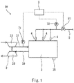
- Fig. 1 shows a gas engine drive system 1A according to Embodiment 1 of the present invention.
- the system 1A includes a gas engine 3, a turbocharger 2, and a controller 6.
- the gas engine 3 may be a pure gas engine that combusts only a fuel gas (e.g., natural gas), or may be a dual fuel engine that combusts one of or both a fuel gas and a fuel oil.
- the gas engine 3 is a 4-stroke engine.
- the gas engine 3 may be a 2-stroke engine.
- the gas engine 3 may be used for power generation on the ground, or may be used as a main engine (electric-propulsion engine or mechanical-propulsion engine) of a ship.
- the gas engine 3 includes a plurality of cylinders (not shown).
- the gas engine 3 is provided with a plurality of fuel injection valves 4 corresponding to the plurality of cylinders, respectively.
- a fuel gas is led to the fuel injection valves 4 through a fuel supply line 5.
- a piston reciprocates twice, and thereby one cycle of the gas engine 3 (intake, compression, expansion, and exhaust) is performed.
- the phase angle (0 to 720 degrees) of the gas engine 3 during one cycle of the cylinder is detected by a phase angle detector 35.
- the rotation angle of a crank shaft i.e., crank angle
- the position of the piston can be used as the phase angle.
- the phase angle detector 35 is an electromagnetic pickup, a proximity switch, or a rotary encoder.
- the actual rotational speed of the gas engine 3 is also detected from the phase angle detector 35.
- the turbocharger 2 includes: a compressor 21 connected to the gas engine 3 by an intake passage 31; and a turbine 22 connected to the gas engine 3 by an exhaust passage 32.
- the intake passage 31 leads intake air from the compressor 21 to all the cylinders of the gas engine 3, and the exhaust passage 32 leads exhaust gas from all the cylinders of the gas engine 3 to the turbine 22.
- the intake passage 31 is provided with a first pressure meter 71, which detects an intake air pressure that is the pressure of the intake air fed to the gas engine 3.
- the aforementioned fuel supply line 5 is provided with a pressure regulating valve 51.
- the fuel supply line 5 is further provided with a second pressure meter 72, which detects a fuel supply pressure that is the pressure at the downstream side of the pressure regulating valve 51.
- the controller 6 controls each of the fuel injection valves 4 based on the phase angle detected by the phase angle detector 35.
- the controller 6 performs PID control of the fuel injection valves 4 to adjust the actual rotational speed of the gas engine 3 to a target rotational speed.
- the controller 6 also controls the pressure regulating valve 51 such that a pressure difference ⁇ P between the fuel supply pressure detected by the second pressure meter 72 and the intake air pressure detected by the first pressure meter 71 is a target value PT.
- the controller 6 determines whether or not the load increases rapidly (step S1). When the load does not increase rapidly (NO in step S1), the controller 6 adopts a first setting value P1 as the aforementioned target value PT, and controls the pressure regulating valve 51 based on the first setting value P1 (step S2). In other words, the controller 6 controls the pressure regulating valve 51 such that the pressure difference ⁇ P between the fuel supply pressure and the intake air pressure is the first setting value P1.
- the determination whether or not the load increases rapidly can be made by various methods. Examples of adoptable methods are as follows.
- step S1 When the load increases rapidly (YES in step S1), the controller 6 adopts a second setting value P2, which is higher than the first setting value P1, as the aforementioned target value PT, and controls the pressure regulating valve 51 based on the second setting value P2 (step S3).
- the controller 6 controls the pressure regulating valve 51 such that the pressure difference ⁇ P between the fuel supply pressure and the intake air pressure is the second setting value P2. That is, when the load increases rapidly, the controller 6 changes the target value PT of the pressure difference ⁇ P between the fuel supply pressure and the intake air pressure from the first setting value P1 to the second setting value P2.
- the first setting value P1 is 0.05 to 0.08 MPa
- the second setting value P2 is 0.1 to 0.2 MPa
- the difference between the first setting value P1 and the second setting value P2 is 0.05 to 0.15 MPa.
- step S4 the controller 6 controls the pressure regulating valve 51 based on the second setting value P2, and when the predetermined time ⁇ T elapses after the rapid increase in the load (YES in step S4), the controller 6 brings the target value PT of the pressure difference ⁇ P between the fuel supply pressure and the intake air pressure back to the first setting value P1 (step S5). Thereafter, the flow returns to step S1.
- step S2 when the load does not increase rapidly (i.e., in step S2), the controller 6 slowly changes the degree of opening of the pressure regulating valve 51, and when the load increases rapidly (i.e., in step S3), the controller 6 quickly changes the degree of opening of the pressure regulating valve 51.
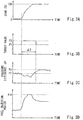
- the load of the gas engine 3 increases rapidly from about 0% to 100% as shown in Fig. 3A .
- the target value PT, the pressure difference ⁇ P, and the fuel injection period transition as shown in Figs. 3B to 3D .
- the pressure difference ⁇ P between the fuel supply pressure and the intake air pressure is increased, and thereby the fuel injection amount from the fuel injection valves per unit injection time can be increased.
- This makes it possible to inject a necessary amount of fuel gas for obtaining a desired output of the gas engine 3 before the fuel injection period reaches its upper limit ⁇ m (e.g., 150 degrees). Consequently, in the case where the load increases rapidly, the desired output of the gas engine 3 can be obtained. Even in a case where the fuel injection period reaches the upper limit ⁇ m as shown in Fig. 3D , since the pressure difference ⁇ P is increased, a larger amount of fuel gas can be injected. Thus, in cases where the load increases rapidly, the possibility of obtaining a desired output of the gas engine 3 is increased.
- the target value PT is brought back from the second setting value P2 to the first setting value P1. Therefore, during normal operation after the rapid increase in the load, the gas engine 3 can be kept operated at such a setting value that optimal performance of the gas engine 3 is obtained.
- the fuel supply line 5 is provided with a calorific value meter 8, which detects the calorific value Q of the fuel gas (e.g., unit: J/Nm 3 ).
- the calorific value meter 8 may be of a sampling type or an online type.
- the controller 6 compares the calorific value Q of the fuel gas, which is detected by the calorific value meter 8, with a threshold ⁇ (step S11). If the calorific value Q is greater than the threshold ⁇ (NO in step S11), the controller 6 adopts the first setting value P1 as the aforementioned target value PT, and controls the pressure regulating valve 51 based on the first setting value P1 (step S12). In other words, the controller 6 controls the pressure regulating valve 51 such that the pressure difference ⁇ P between the fuel supply pressure and the intake air pressure is the first setting value P1.
- the controller 6 adopts the second setting value P2, which is higher than the first setting value P1, as the target value PT, and controls the pressure regulating valve 51 based on the second setting value P2 (step S13).
- the controller 6 controls the pressure regulating valve 51 such that the pressure difference ⁇ P between the fuel supply pressure and the intake air pressure is the second setting value P2. That is, when the calorific value Q is less than the threshold ⁇ , the controller 6 changes the target value PT of the pressure difference ⁇ P between the fuel supply pressure and the intake air pressure from the first setting value P1 to the second setting value P2.
- the first setting value P1 is 0.05 to 0.07 MPa.
- the controller 6 prestores therein a map in which the second setting value P2 is defined in association with the calorific value Q. As shown in Fig. 6 , the present embodiment adopts a map in which the second setting value P2 increases in accordance with decrease in the calorific value Q of the fuel gas. Accordingly, when adopting the second setting value P2 in step S 13, the controller 6 determines the second setting value P2 such that the less the calorific value Q of the fuel gas, the greater the second setting value P2. For example, within a particular range of the calorific value Q, the second setting value P2 decreases linearly from its maximum value (e.g., 0.1 to 0.2 MPa) to the first setting value P1.
- its maximum value e.g., 0.1 to 0.2 MPa
- the calorific value Q of the fuel gas decreases from a value greater than the threshold ⁇ to a value less than the threshold ⁇ as shown in Fig. 7A .
- the target value PT transitions as shown in Fig. 7B .
- the pressure difference ⁇ P between the fuel supply pressure and the intake air pressure is increased, and thereby the fuel injection amount from the fuel injection valves 4 per unit injection time can be increased.
- This makes it possible to inject a necessary amount of fuel gas for obtaining a desired output of the gas engine 3 before the fuel injection period reaches its upper limit. Consequently, in the case where the calorific value Q of the fuel gas is low, the desired output of the gas engine 3 can be obtained. Even in a case where the fuel injection period reaches the upper limit, since the pressure difference ⁇ P is increased, a larger amount of fuel gas can be injected.
- the calorific value of the fuel gas is low, the possibility of obtaining a desired output of the gas engine 3 is increased.
- the second setting value P2 is determined such that the less the calorific value Q of the fuel gas, the greater the second setting value P2. Therefore, the fuel injection amount can be increased in accordance with decrease in the calorific value Q of the fuel gas. This makes it possible to maintain the output of the gas engine 3 even if the calorific value Q of the fuel gas is low.
- the target value PT is changed from the first setting value P1 to the second setting value P2. This makes it possible to maintain the output of the gas engine 3 even immediately after rapid change in the calorific value Q of the fuel gas.
- the present embodiment similar to Embodiment 2, when the calorific value Q of the fuel gas is less than the threshold ⁇ , the target value PT of the pressure difference ⁇ P between the fuel supply pressure and the intake air pressure is changed from the first setting value P1 to the second setting value P2.
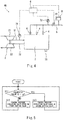
- the present embodiment does not include the calorific value meter 8. Instead, the gas engine 3 drives a power generator 9, and electric power generated by the power generator 9 is detected by a power meter 91.
- step S11 described in Embodiment 2 the controller 6 calculates the calorific value Q of the fuel gas based on the electric power detected by the power meter 91 and the fuel injection amount from the fuel injection valves 4 (step S21). Thereafter, the same processes as those performed in Embodiment 2 are performed.
- a torque meter 92 which detects the output torque of the gas engine 3 may be provided instead of the power generator 9 and the power meter 91, and the calorific value Q of the fuel gas can be calculated based on the output torque of the gas engine 3, which is detected by the torque meter 92, and the fuel injection amount.
- Embodiment 1 may be combined with Embodiment 2 or 3. That is, the controller 6 may perform both the determination of step S1 shown in Fig. 2 and the determination of step S11 shown in Fig. 5 and Fig. 9 .
Landscapes
- Engineering & Computer Science (AREA)
- Chemical & Material Sciences (AREA)
- Combustion & Propulsion (AREA)
- Mechanical Engineering (AREA)
- General Engineering & Computer Science (AREA)
- Chemical Kinetics & Catalysis (AREA)
- General Chemical & Material Sciences (AREA)
- Oil, Petroleum & Natural Gas (AREA)
- Output Control And Ontrol Of Special Type Engine (AREA)
- Electrical Control Of Air Or Fuel Supplied To Internal-Combustion Engine (AREA)
- Supercharger (AREA)
- Combined Controls Of Internal Combustion Engines (AREA)
Abstract
Description
- The present invention relates to a gas engine drive system including a gas engine and a turbocharger.
- Conventionally, there is a known gas engine drive system including a gas engine and a turbocharger (see
Patent Literature 1, for example). The turbocharger includes a compressor and a turbine that are connected to the gas engine. The gas engine is provided with a fuel injection valve, and a fuel gas is led to the fuel injection valve through a fuel supply line. The fuel supply line is provided with a pressure regulating valve. Generally speaking, the pressure regulating valve is controlled such that the pressure difference between the fuel supply pressure and intake air pressure is constant. - PTL 1: Japanese Laid-Open Patent Application Publication No.
2011-132893 - In a case where the load on the gas engine increases rapidly or in a case where the calorific value of the fuel gas is low, the gas engine requires a large amount of fuel gas. However, the fuel injection period of the fuel injection valve has an upper limit. Therefore, when the load on the gas engine increases rapidly or when the calorific value of the fuel gas is low, there is a case where a necessary amount of fuel gas for obtaining a desired output of the gas engine cannot be injected.
- In view of the above, an object of the present invention is to provide a gas engine drive system that is capable of obtaining a desired output of a gas engine in a case where the load on the gas engine increases rapidly or in a case where the calorific value of the fuel gas is low.
- In order to solve the above-described problems, a gas engine drive system according to the present invention includes: a gas engine; a turbocharger including a compressor and a turbine that are connected to the gas engine; a fuel injection valve provided on the gas engine; a fuel supply line that leads a fuel gas to the fuel injection valve, the fuel supply line being provided with a pressure regulating valve; a first pressure meter that detects an intake air pressure that is a pressure of intake air fed from the compressor to the gas engine; a second pressure meter that detects a fuel supply pressure that is a pressure at a downstream side of the pressure regulating valve; and a controller that controls the pressure regulating valve such that a pressure difference between the fuel supply pressure detected by the second pressure meter and the intake air pressure detected by the first pressure meter is a target value. The controller changes the target value from a first setting value to a second setting value higher than the first setting value when a load on the gas engine increases rapidly or when a calorific value of the fuel gas is less than a threshold.
- According to the above configuration, in a case where the load increases rapidly or in a case where the calorific value of the fuel gas is low, the pressure difference between the fuel supply pressure and the intake air pressure is increased, and thereby the fuel injection amount from the fuel injection valve per unit injection time can be increased. This makes it possible to inject a necessary amount of fuel gas for obtaining a desired output of the gas engine before the fuel injection period reaches its upper limit. Consequently, in the case where the load increases rapidly or in the case where the calorific value of the fuel gas is low, the desired output of the gas engine can be obtained.
- When the load on the gas engine increases rapidly, the controller may change the target value from the first setting value to the second setting value, and when a predetermined time elapses after the rapid increase in the load on the gas engine, the controller may bring the target value back to the first setting value. According to this configuration, during normal operation after the rapid increase in the load, the gas engine can be kept operated at such a setting value that optimal performance of the gas engine is obtained.
- When the calorific value of the fuel gas is less than the threshold, the controller may determine the second setting value such that the less the calorific value of the fuel gas, the greater the second setting value, and change the target value from the first setting value to the second setting value. According to this configuration, the fuel injection amount can be increased in accordance with decrease in the calorific value of the fuel gas. This makes it possible to maintain the output of the gas engine even if the calorific value of the fuel gas is low.
- The above gas engine drive system may further include a calorific value meter that detects the calorific value of the fuel gas. The controller may change the target value from the first setting value to the second setting value when the calorific value of the fuel gas, which is detected by the calorific value meter, is less than the threshold. This configuration makes it possible to maintain the output of the gas engine even immediately after rapid change in the calorific value of the fuel gas.
- The above gas engine drive system may further include: a power generator that is driven by the gas engine; and a power meter that detects electric power generated by the power generator. The controller may calculate the calorific value of the fuel gas based on the electric power detected by the power meter and a fuel injection amount from the fuel injection valve, and change the target value from the first setting value to the second setting value when the calculated calorific value is equal to or less than the threshold. This configuration makes it possible to maintain the output of the gas engine even immediately after rapid change in the calorific value of the fuel gas without using a calorific value meter.
- The above gas engine drive system may further include a torque meter that detects an output torque of the gas engine. The controller may calculate the calorific value of the fuel gas based on the output torque of the gas engine, which is detected by the torque meter, and a fuel injection amount from the fuel injection valve, and change the target value from the first setting value to the second setting value when the calculated calorific value is equal to or less than the threshold. This configuration makes it possible to maintain the output of the gas engine even immediately after rapid change in the calorific value of the fuel gas without using a calorific value meter.
- The present invention makes it possible to obtain a desired output of the gas engine in a case where the load on the gas engine increases rapidly or in a case where the calorific value of the fuel gas is low.
-
-
Fig. 1 shows a schematic configuration of a gas engine drive system according toEmbodiment 1 of the present invention. -
Fig. 2 is a flowchart of control performed by a controller inEmbodiment 1. -
Fig. 3A is a graph showing temporal changes in the load on a gas engine;Fig. 3B is a graph showing temporal changes in a target value of a pressure difference between a fuel supply pressure and an intake air pressure;Fig. 3C is a graph showing temporal changes in the pressure difference; andFig. 3D is a graph showing temporal changes in a fuel injection period. -
Fig. 4 shows a schematic configuration of a gas engine drive system according toEmbodiment 2 of the present invention. -
Fig. 5 is a flowchart of control performed by the controller inEmbodiment 2. -
Fig. 6 shows a relationship between a calorific value and a second setting value. -
Fig. 7A is a graph showing temporal changes in the calorific value, andFig. 7B is a graph showing temporal changes in the target value of the pressure difference between the fuel supply pressure and the intake air pressure. -
Fig. 8 shows a schematic configuration of a gas engine drive system according toEmbodiment 3 of the present invention. -
Fig. 9 is a flowchart of control performed by the controller inEmbodiment 3. -
Fig. 10 shows a schematic configuration of a gas engine drive system according to one variation ofEmbodiment 3. -
Fig. 1 shows a gas engine drive system 1A according toEmbodiment 1 of the present invention. The system 1A includes agas engine 3, aturbocharger 2, and acontroller 6. - The
gas engine 3 may be a pure gas engine that combusts only a fuel gas (e.g., natural gas), or may be a dual fuel engine that combusts one of or both a fuel gas and a fuel oil. In the present embodiment, thegas engine 3 is a 4-stroke engine. However, as an alternative, thegas engine 3 may be a 2-stroke engine. For example, thegas engine 3 may be used for power generation on the ground, or may be used as a main engine (electric-propulsion engine or mechanical-propulsion engine) of a ship. - The
gas engine 3 includes a plurality of cylinders (not shown). Thegas engine 3 is provided with a plurality offuel injection valves 4 corresponding to the plurality of cylinders, respectively. A fuel gas is led to thefuel injection valves 4 through afuel supply line 5. - In each cylinder, a piston reciprocates twice, and thereby one cycle of the gas engine 3 (intake, compression, expansion, and exhaust) is performed. The phase angle (0 to 720 degrees) of the
gas engine 3 during one cycle of the cylinder is detected by aphase angle detector 35. For example, the rotation angle of a crank shaft (i.e., crank angle) or the position of the piston can be used as the phase angle. For example, thephase angle detector 35 is an electromagnetic pickup, a proximity switch, or a rotary encoder. The actual rotational speed of thegas engine 3 is also detected from thephase angle detector 35. - The
turbocharger 2 includes: acompressor 21 connected to thegas engine 3 by anintake passage 31; and aturbine 22 connected to thegas engine 3 by anexhaust passage 32. Theintake passage 31 leads intake air from thecompressor 21 to all the cylinders of thegas engine 3, and theexhaust passage 32 leads exhaust gas from all the cylinders of thegas engine 3 to theturbine 22. Theintake passage 31 is provided with afirst pressure meter 71, which detects an intake air pressure that is the pressure of the intake air fed to thegas engine 3. - The aforementioned
fuel supply line 5 is provided with apressure regulating valve 51. Thefuel supply line 5 is further provided with asecond pressure meter 72, which detects a fuel supply pressure that is the pressure at the downstream side of thepressure regulating valve 51. - The
controller 6 controls each of thefuel injection valves 4 based on the phase angle detected by thephase angle detector 35. Thecontroller 6 performs PID control of thefuel injection valves 4 to adjust the actual rotational speed of thegas engine 3 to a target rotational speed. Thecontroller 6 also controls thepressure regulating valve 51 such that a pressure difference ΔP between the fuel supply pressure detected by thesecond pressure meter 72 and the intake air pressure detected by thefirst pressure meter 71 is a target value PT. - Next, control of the
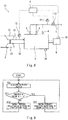
pressure regulating valve 51 is described in detail with reference toFig. 2 . - The
controller 6 determines whether or not the load increases rapidly (step S1). When the load does not increase rapidly (NO in step S1), thecontroller 6 adopts a first setting value P1 as the aforementioned target value PT, and controls thepressure regulating valve 51 based on the first setting value P1 (step S2). In other words, thecontroller 6 controls thepressure regulating valve 51 such that the pressure difference ΔP between the fuel supply pressure and the intake air pressure is the first setting value P1. - The determination whether or not the load increases rapidly can be made by various methods. Examples of adoptable methods are as follows.
- (1) One example method includes: calculating the speed of increase in a necessary fuel injection amount; and determining that the load increases rapidly if the speed of increase in the necessary fuel injection amount is higher than a threshold, and determining that the load does not increase rapidly if the speed of increase in the necessary fuel injection amount is lower than the threshold.
- (2) Another example method includes: calculating a deviation between the actual rotational speed and the target rotational speed; and determining that the load increases rapidly if the deviation between the actual rotational speed and the target rotational speed is greater than a threshold, and determining that the load does not increase rapidly if the deviation between the actual rotational speed and the target rotational speed is less than the threshold.
- (3) Yet another example method includes: detecting the output torque of the
gas engine 3 by a torque meter and calculating the speed of increase in the output torque; and determining that the load increases rapidly if the speed of increase in the output torque is higher than a threshold, and determining that the load does not increase rapidly if the speed of increase in the output torque is lower than the threshold. - When the load increases rapidly (YES in step S1), the
controller 6 adopts a second setting value P2, which is higher than the first setting value P1, as the aforementioned target value PT, and controls thepressure regulating valve 51 based on the second setting value P2 (step S3). In other words, thecontroller 6 controls thepressure regulating valve 51 such that the pressure difference ΔP between the fuel supply pressure and the intake air pressure is the second setting value P2. That is, when the load increases rapidly, thecontroller 6 changes the target value PT of the pressure difference ΔP between the fuel supply pressure and the intake air pressure from the first setting value P1 to the second setting value P2. - For example, the first setting value P1 is 0.05 to 0.08 MPa; the second setting value P2 is 0.1 to 0.2 MPa; and the difference between the first setting value P1 and the second setting value P2 is 0.05 to 0.15 MPa.
- Then, until a predetermined time ΔT elapses after the rapid increase in the load (NO in step S4), the
controller 6 controls thepressure regulating valve 51 based on the second setting value P2, and when the predetermined time ΔT elapses after the rapid increase in the load (YES in step S4), thecontroller 6 brings the target value PT of the pressure difference ΔP between the fuel supply pressure and the intake air pressure back to the first setting value P1 (step S5). Thereafter, the flow returns to step S1. - Desirably, when the load does not increase rapidly (i.e., in step S2), the
controller 6 slowly changes the degree of opening of thepressure regulating valve 51, and when the load increases rapidly (i.e., in step S3), thecontroller 6 quickly changes the degree of opening of thepressure regulating valve 51. - As one example, assume that the load of the
gas engine 3 increases rapidly from about 0% to 100% as shown inFig. 3A . At the time, the target value PT, the pressure difference ΔP, and the fuel injection period transition as shown inFigs. 3B to 3D . - As described above, in the gas engine drive system 1A according to the present embodiment, in a case where the load increases rapidly, the pressure difference ΔP between the fuel supply pressure and the intake air pressure is increased, and thereby the fuel injection amount from the fuel injection valves per unit injection time can be increased. This makes it possible to inject a necessary amount of fuel gas for obtaining a desired output of the
gas engine 3 before the fuel injection period reaches its upper limit θm (e.g., 150 degrees). Consequently, in the case where the load increases rapidly, the desired output of thegas engine 3 can be obtained. Even in a case where the fuel injection period reaches the upper limit θm as shown inFig. 3D , since the pressure difference ΔP is increased, a larger amount of fuel gas can be injected. Thus, in cases where the load increases rapidly, the possibility of obtaining a desired output of thegas engine 3 is increased. - Moreover, when the predetermined time ΔT elapses after the rapid increase in the load of the
gas engine 3, the target value PT is brought back from the second setting value P2 to the first setting value P1. Therefore, during normal operation after the rapid increase in the load, thegas engine 3 can be kept operated at such a setting value that optimal performance of thegas engine 3 is obtained. - Next, a gas
engine drive system 1B according toEmbodiment 2 of the present invention is described with reference toFig. 4 and Fig. 5 . It should be noted that, in the present embodiment and the followingEmbodiment 3, the same components as those described inEmbodiment 1 are denoted by the same reference signs as those used inEmbodiment 1, and repeating the same descriptions is avoided. - In the present embodiment, the
fuel supply line 5 is provided with acalorific value meter 8, which detects the calorific value Q of the fuel gas (e.g., unit: J/Nm3). Thecalorific value meter 8 may be of a sampling type or an online type. - As shown in
Fig. 5 , first, thecontroller 6 compares the calorific value Q of the fuel gas, which is detected by thecalorific value meter 8, with a threshold α (step S11). If the calorific value Q is greater than the threshold α (NO in step S11), thecontroller 6 adopts the first setting value P1 as the aforementioned target value PT, and controls thepressure regulating valve 51 based on the first setting value P1 (step S12). In other words, thecontroller 6 controls thepressure regulating valve 51 such that the pressure difference ΔP between the fuel supply pressure and the intake air pressure is the first setting value P1. - On the other hand, if the calorific value Q is less than the threshold α (YES in step S11), the
controller 6 adopts the second setting value P2, which is higher than the first setting value P1, as the target value PT, and controls thepressure regulating valve 51 based on the second setting value P2 (step S13). In other words, thecontroller 6 controls thepressure regulating valve 51 such that the pressure difference ΔP between the fuel supply pressure and the intake air pressure is the second setting value P2. That is, when the calorific value Q is less than the threshold α, thecontroller 6 changes the target value PT of the pressure difference ΔP between the fuel supply pressure and the intake air pressure from the first setting value P1 to the second setting value P2. - For example, the first setting value P1 is 0.05 to 0.07 MPa. The
controller 6 prestores therein a map in which the second setting value P2 is defined in association with the calorific value Q. As shown inFig. 6 , the present embodiment adopts a map in which the second setting value P2 increases in accordance with decrease in the calorific value Q of the fuel gas. Accordingly, when adopting the second setting value P2 instep S 13, thecontroller 6 determines the second setting value P2 such that the less the calorific value Q of the fuel gas, the greater the second setting value P2. For example, within a particular range of the calorific value Q, the second setting value P2 decreases linearly from its maximum value (e.g., 0.1 to 0.2 MPa) to the first setting value P1. - As one example, assume that the calorific value Q of the fuel gas decreases from a value greater than the threshold α to a value less than the threshold α as shown in
Fig. 7A . At the time, the target value PT transitions as shown inFig. 7B . - As described above, in the gas
engine drive system 1B of the present embodiment, in a case where the calorific value Q of the fuel gas is low, the pressure difference ΔP between the fuel supply pressure and the intake air pressure is increased, and thereby the fuel injection amount from thefuel injection valves 4 per unit injection time can be increased. This makes it possible to inject a necessary amount of fuel gas for obtaining a desired output of thegas engine 3 before the fuel injection period reaches its upper limit. Consequently, in the case where the calorific value Q of the fuel gas is low, the desired output of thegas engine 3 can be obtained. Even in a case where the fuel injection period reaches the upper limit, since the pressure difference ΔP is increased, a larger amount of fuel gas can be injected. Thus, in cases where the calorific value of the fuel gas is low, the possibility of obtaining a desired output of thegas engine 3 is increased. - Moreover, the second setting value P2 is determined such that the less the calorific value Q of the fuel gas, the greater the second setting value P2. Therefore, the fuel injection amount can be increased in accordance with decrease in the calorific value Q of the fuel gas. This makes it possible to maintain the output of the
gas engine 3 even if the calorific value Q of the fuel gas is low. - Furthermore, in the present embodiment, when the calorific value Q of the fuel gas, which is detected by the
calorific value meter 8, is less than the threshold α, the target value PT is changed from the first setting value P1 to the second setting value P2. This makes it possible to maintain the output of thegas engine 3 even immediately after rapid change in the calorific value Q of the fuel gas. - Next, a gas engine drive system 1C according to
Embodiment 3 of the present invention is described with reference toFig. 8 and Fig. 9 . - In the present embodiment, similar to
Embodiment 2, when the calorific value Q of the fuel gas is less than the threshold α, the target value PT of the pressure difference ΔP between the fuel supply pressure and the intake air pressure is changed from the first setting value P1 to the second setting value P2. However, the present embodiment does not include thecalorific value meter 8. Instead, thegas engine 3 drives apower generator 9, and electric power generated by thepower generator 9 is detected by apower meter 91. - As shown in
Fig. 9 , in the present embodiment, before step S11 described inEmbodiment 2, thecontroller 6 calculates the calorific value Q of the fuel gas based on the electric power detected by thepower meter 91 and the fuel injection amount from the fuel injection valves 4 (step S21). Thereafter, the same processes as those performed inEmbodiment 2 are performed. - The present embodiment provides the same advantageous effects as those provided by
Embodiment 2. It should be noted that, as shown inFig. 10 , atorque meter 92, which detects the output torque of thegas engine 3, may be provided instead of thepower generator 9 and thepower meter 91, and the calorific value Q of the fuel gas can be calculated based on the output torque of thegas engine 3, which is detected by thetorque meter 92, and the fuel injection amount. - The present invention is not limited to the above-described
Embodiments 1 to 3. Various modifications can be made without departing from the spirit of the present invention. - For example,
Embodiment 1 may be combined withEmbodiment controller 6 may perform both the determination of step S1 shown inFig. 2 and the determination of step S11 shown inFig. 5 andFig. 9 . -
- 1A to 1C
- gas engine drive system
- 3
- gas engine
- 4
- fuel injection valve
- 5
- fuel supply line
- 51
- pressure regulating valve
- 6
- controller
- 71
- first pressure meter
- 72
- second pressure meter
- 8
- calorific value meter
- 9
- power generator
- 91
- power meter
- 92
- torque meter
Claims (6)
- A gas engine drive system comprising:a gas engine;a turbocharger including a compressor and a turbine that are connected to the gas engine;a fuel injection valve provided on the gas engine;a fuel supply line that leads a fuel gas to the fuel injection valve, the fuel supply line being provided with a pressure regulating valve;a first pressure meter that detects an intake air pressure that is a pressure of intake air fed from the compressor to the gas engine;a second pressure meter that detects a fuel supply pressure that is a pressure at a downstream side of the pressure regulating valve; anda controller that controls the pressure regulating valve such that a pressure difference between the fuel supply pressure detected by the second pressure meter and the intake air pressure detected by the first pressure meter is a target value, whereinthe controller changes the target value from a first setting value to a second setting value higher than the first setting value when a load on the gas engine increases rapidly or when a calorific value of the fuel gas is less than a threshold.
- The gas engine drive system according to claim 1, wherein
when the load on the gas engine increases rapidly, the controller changes the target value from the first setting value to the second setting value, and when a predetermined time elapses after the rapid increase in the load on the gas engine, the controller brings the target value back to the first setting value. - The gas engine drive system according to claim 1, wherein
when the calorific value of the fuel gas is less than the threshold, the controller determines the second setting value such that the less the calorific value of the fuel gas, the greater the second setting value, and changes the target value from the first setting value to the second setting value. - The gas engine drive system according to claim 1 or 3, further comprising a calorific value meter that detects the calorific value of the fuel gas, wherein
the controller changes the target value from the first setting value to the second setting value when the calorific value of the fuel gas, which is detected by the calorific value meter, is less than the threshold. - The gas engine drive system according to claim 1 or 3, further comprising:a power generator that is driven by the gas engine; anda power meter that detects electric power generated by the power generator, whereinthe controller calculates the calorific value of the fuel gas based on the electric power detected by the power meter and a fuel injection amount from the fuel injection valve, and changes the target value from the first setting value to the second setting value when the calculated calorific value is equal to or less than the threshold.
- The gas engine drive system according to claim 1 or 3, further comprising a torque meter that detects an output torque of the gas engine, wherein
the controller calculates the calorific value of the fuel gas based on the output torque of the gas engine, which is detected by the torque meter, and a fuel injection amount from the fuel injection valve, and changes the target value from the first setting value to the second setting value when the calculated calorific value is equal to or less than the threshold.
Applications Claiming Priority (2)
| Application Number | Priority Date | Filing Date | Title |
|---|---|---|---|
| JP2015220070A JP6047217B1 (en) | 2015-11-10 | 2015-11-10 | Gas engine drive system |
| PCT/JP2016/079827 WO2017081966A1 (en) | 2015-11-10 | 2016-10-06 | Gas engine drive system |
Publications (3)
| Publication Number | Publication Date |
|---|---|
| EP3376012A1 true EP3376012A1 (en) | 2018-09-19 |
| EP3376012A4 EP3376012A4 (en) | 2019-03-06 |
| EP3376012B1 EP3376012B1 (en) | 2020-11-25 |
Family
ID=57572417
Family Applications (1)
| Application Number | Title | Priority Date | Filing Date |
|---|---|---|---|
| EP16863930.0A Active EP3376012B1 (en) | 2015-11-10 | 2016-10-06 | Gas engine drive system |
Country Status (4)
| Country | Link |
|---|---|
| US (1) | US10480445B2 (en) |
| EP (1) | EP3376012B1 (en) |
| JP (1) | JP6047217B1 (en) |
| WO (1) | WO2017081966A1 (en) |
Families Citing this family (2)
| Publication number | Priority date | Publication date | Assignee | Title |
|---|---|---|---|---|
| WO2019171578A1 (en) * | 2018-03-09 | 2019-09-12 | 三菱重工業株式会社 | Control device for gas engine, gas engine system, and gas engine control method |
| CN113074052B (en) * | 2021-05-07 | 2023-04-18 | 潍柴动力股份有限公司 | Gas pressure control method of hybrid vehicle and hybrid vehicle |
Family Cites Families (24)
| Publication number | Priority date | Publication date | Assignee | Title |
|---|---|---|---|---|
| US3303348A (en) * | 1964-08-11 | 1967-02-07 | Nordberg Manufacturing Co | Engine air-fuel ratio control in response to generator output |
| JPS58206838A (en) * | 1982-05-28 | 1983-12-02 | Hitachi Ltd | System for supplying fuel into electronic control cylinder |
| JP3490237B2 (en) * | 1996-12-26 | 2004-01-26 | 新潟原動機株式会社 | Pilot gas pressure control device and pressure control method |
| JP4418124B2 (en) * | 2001-04-19 | 2010-02-17 | 三菱重工業株式会社 | Sub-chamber differential pressure control device for gas engine |
| JP4452092B2 (en) * | 2004-02-24 | 2010-04-21 | 三菱重工業株式会社 | Combustion control method and apparatus for gas engine |
| DE102004060905A1 (en) * | 2004-12-17 | 2006-06-29 | Robert Bosch Gmbh | Method for controlling an internal combustion engine to which a gaseous fuel is supplied and apparatus for reducing the pressure of a gas |
| US8113181B2 (en) * | 2005-03-09 | 2012-02-14 | Rem Technology Inc. | Method and apparatus for capturing and controlling fugitive gases |
| DE102005016281B4 (en) * | 2005-04-08 | 2010-01-14 | Continental Automotive Gmbh | Operating method and apparatus for a gas powered internal combustion engine |
| JP4520893B2 (en) * | 2005-04-08 | 2010-08-11 | アイシン精機株式会社 | Engine mixer, engine-driven air conditioner, engine-driven power generator |
| CA2505455C (en) * | 2005-05-18 | 2007-02-20 | Westport Research Inc. | Direct injection gaseous fuelled engine and method of controlling fuel injection pressure |
| JP4698471B2 (en) * | 2006-03-31 | 2011-06-08 | 大阪瓦斯株式会社 | engine |
| US7377267B2 (en) * | 2006-10-30 | 2008-05-27 | Ford Global Technologies, Llc | Injection strategy to maximize efficiency in gaseous engine |
| JP4379479B2 (en) * | 2007-02-28 | 2009-12-09 | 株式会社日立製作所 | In-cylinder injection engine control method, control device for implementing the control method, and control circuit device used in the control device |
| JP4755155B2 (en) * | 2007-08-30 | 2011-08-24 | 三菱重工業株式会社 | Integrated control method and apparatus for gas engine |
| JP4563443B2 (en) * | 2007-12-14 | 2010-10-13 | 三菱重工業株式会社 | Gas engine system control method and system |
| JP5090974B2 (en) * | 2008-03-14 | 2012-12-05 | 大阪瓦斯株式会社 | engine |
| JP4977752B2 (en) * | 2009-12-24 | 2012-07-18 | 川崎重工業株式会社 | Control device and control method for gas engine |
| WO2011080917A1 (en) * | 2009-12-28 | 2011-07-07 | 川崎重工業株式会社 | Auxiliary chamber-type gas engine |
| JP2012087758A (en) * | 2010-10-22 | 2012-05-10 | Yanmar Co Ltd | Engine control method |
| JP5308466B2 (en) * | 2011-01-31 | 2013-10-09 | 三菱重工業株式会社 | Fuel gas supply method and apparatus for gas engine |
| JP6128975B2 (en) * | 2013-06-11 | 2017-05-17 | ヤンマー株式会社 | Gas engine |
| JP6134587B2 (en) * | 2013-06-11 | 2017-05-24 | ヤンマー株式会社 | Gas engine |
| JP6399682B2 (en) * | 2013-09-04 | 2018-10-03 | 大阪瓦斯株式会社 | Engine-driven heat pump device and calorific value estimation method |
| JP6296810B2 (en) * | 2014-01-24 | 2018-03-20 | ヤンマー株式会社 | Gas engine |
-
2015
- 2015-11-10 JP JP2015220070A patent/JP6047217B1/en active Active
-
2016
- 2016-10-06 WO PCT/JP2016/079827 patent/WO2017081966A1/en active Application Filing
- 2016-10-06 EP EP16863930.0A patent/EP3376012B1/en active Active
- 2016-10-06 US US15/775,113 patent/US10480445B2/en active Active
Also Published As
| Publication number | Publication date |
|---|---|
| EP3376012B1 (en) | 2020-11-25 |
| JP2017089484A (en) | 2017-05-25 |
| WO2017081966A1 (en) | 2017-05-18 |
| EP3376012A4 (en) | 2019-03-06 |
| US20180372017A1 (en) | 2018-12-27 |
| US10480445B2 (en) | 2019-11-19 |
| JP6047217B1 (en) | 2016-12-21 |
Similar Documents
| Publication | Publication Date | Title |
|---|---|---|
| US8510013B2 (en) | Gas turbine shutdown | |
| RU2706853C2 (en) | Method (embodiments) and fuel system control system | |
| EP2518299A1 (en) | Device and method of controlling gas engine | |
| US10480426B2 (en) | Method of controlling gas engine and gas engine drive system | |
| EP2339148A2 (en) | Method and system for controlling a fuel flow to a turbomachine | |
| EP3376012A1 (en) | Gas engine drive system | |
| JP6389572B2 (en) | Control device for supercharging system | |
| EP2500546A1 (en) | System and method for controlling a fuel supply associated with a turbomachine | |
| JP6333621B2 (en) | Fuel supply device for internal combustion engine | |
| JP6134616B2 (en) | 2-shaft gas turbine | |
| US10612460B2 (en) | Method and device for rotational speed control of an electrically operated supercharging device for an internal combustion engine | |
| JP5804756B2 (en) | Supercharger system, internal combustion engine, and supercharger system control method | |
| US9850841B2 (en) | System and program product for controlling exhaust gas temperature of engine system | |
| KR101760000B1 (en) | Engine system and ship | |
| JP2006307676A (en) | Fuel control device and operating method of diesel engine for power generation | |
| JP6509610B2 (en) | Control method of supercharged internal combustion engine and supercharger internal combustion engine | |
| KR101861858B1 (en) | Method and device for operating an internal combustion engine | |
| RU174395U1 (en) | Gas turbine compressor mechanization control device | |
| JP5904806B2 (en) | Engine and engine control method | |
| KR101134694B1 (en) | Method for calculating control reference value of diesel engine | |
| KR20200048889A (en) | Apparatus for controlling engine with variable geometry turbo-charger | |
| JP2019060249A (en) | Fuel injection control device for internal combustion engine | |
| JP2019173633A (en) | Fuel supply control method and fuel supply control system | |
| KR20150118445A (en) | Methods of controlling engine system | |
| JP2009250126A (en) | Controller of gas turbine engine |
Legal Events
| Date | Code | Title | Description |
|---|---|---|---|
| STAA | Information on the status of an ep patent application or granted ep patent |
Free format text: STATUS: THE INTERNATIONAL PUBLICATION HAS BEEN MADE |
|
| PUAI | Public reference made under article 153(3) epc to a published international application that has entered the european phase |
Free format text: ORIGINAL CODE: 0009012 |
|
| STAA | Information on the status of an ep patent application or granted ep patent |
Free format text: STATUS: REQUEST FOR EXAMINATION WAS MADE |
|
| 17P | Request for examination filed |
Effective date: 20180525 |
|
| AK | Designated contracting states |
Kind code of ref document: A1 Designated state(s): AL AT BE BG CH CY CZ DE DK EE ES FI FR GB GR HR HU IE IS IT LI LT LU LV MC MK MT NL NO PL PT RO RS SE SI SK SM TR |
|
| AX | Request for extension of the european patent |
Extension state: BA ME |
|
| DAV | Request for validation of the european patent (deleted) | ||
| DAX | Request for extension of the european patent (deleted) | ||
| A4 | Supplementary search report drawn up and despatched |
Effective date: 20190204 |
|
| RIC1 | Information provided on ipc code assigned before grant |
Ipc: F02D 19/02 20060101ALI20190129BHEP Ipc: F02D 41/04 20060101ALI20190129BHEP Ipc: F02D 41/00 20060101ALI20190129BHEP Ipc: F02D 41/02 20060101ALI20190129BHEP Ipc: F02M 21/02 20060101AFI20190129BHEP Ipc: F02B 37/00 20060101ALI20190129BHEP Ipc: F02D 45/00 20060101ALI20190129BHEP |
|
| GRAP | Despatch of communication of intention to grant a patent |
Free format text: ORIGINAL CODE: EPIDOSNIGR1 |
|
| STAA | Information on the status of an ep patent application or granted ep patent |
Free format text: STATUS: GRANT OF PATENT IS INTENDED |
|
| INTG | Intention to grant announced |
Effective date: 20200713 |
|
| GRAS | Grant fee paid |
Free format text: ORIGINAL CODE: EPIDOSNIGR3 |
|
| GRAA | (expected) grant |
Free format text: ORIGINAL CODE: 0009210 |
|
| STAA | Information on the status of an ep patent application or granted ep patent |
Free format text: STATUS: THE PATENT HAS BEEN GRANTED |
|
| AK | Designated contracting states |
Kind code of ref document: B1 Designated state(s): AL AT BE BG CH CY CZ DE DK EE ES FI FR GB GR HR HU IE IS IT LI LT LU LV MC MK MT NL NO PL PT RO RS SE SI SK SM TR |
|
| REG | Reference to a national code |
Ref country code: GB Ref legal event code: FG4D |
|
| REG | Reference to a national code |
Ref country code: CH Ref legal event code: EP |
|
| REG | Reference to a national code |
Ref country code: AT Ref legal event code: REF Ref document number: 1338603 Country of ref document: AT Kind code of ref document: T Effective date: 20201215 |
|
| REG | Reference to a national code |
Ref country code: DE Ref legal event code: R096 Ref document number: 602016048809 Country of ref document: DE |
|
| REG | Reference to a national code |
Ref country code: IE Ref legal event code: FG4D |
|
| REG | Reference to a national code |
Ref country code: FI Ref legal event code: FGE |
|
| REG | Reference to a national code |
Ref country code: NO Ref legal event code: T2 Effective date: 20201125 |
|
| REG | Reference to a national code |
Ref country code: NL Ref legal event code: MP Effective date: 20201125 |
|
| PG25 | Lapsed in a contracting state [announced via postgrant information from national office to epo] |
Ref country code: GR Free format text: LAPSE BECAUSE OF FAILURE TO SUBMIT A TRANSLATION OF THE DESCRIPTION OR TO PAY THE FEE WITHIN THE PRESCRIBED TIME-LIMIT Effective date: 20210226 Ref country code: RS Free format text: LAPSE BECAUSE OF FAILURE TO SUBMIT A TRANSLATION OF THE DESCRIPTION OR TO PAY THE FEE WITHIN THE PRESCRIBED TIME-LIMIT Effective date: 20201125 Ref country code: PT Free format text: LAPSE BECAUSE OF FAILURE TO SUBMIT A TRANSLATION OF THE DESCRIPTION OR TO PAY THE FEE WITHIN THE PRESCRIBED TIME-LIMIT Effective date: 20210325 |
|
| PG25 | Lapsed in a contracting state [announced via postgrant information from national office to epo] |
Ref country code: BG Free format text: LAPSE BECAUSE OF FAILURE TO SUBMIT A TRANSLATION OF THE DESCRIPTION OR TO PAY THE FEE WITHIN THE PRESCRIBED TIME-LIMIT Effective date: 20210225 Ref country code: PL Free format text: LAPSE BECAUSE OF FAILURE TO SUBMIT A TRANSLATION OF THE DESCRIPTION OR TO PAY THE FEE WITHIN THE PRESCRIBED TIME-LIMIT Effective date: 20201125 Ref country code: IS Free format text: LAPSE BECAUSE OF FAILURE TO SUBMIT A TRANSLATION OF THE DESCRIPTION OR TO PAY THE FEE WITHIN THE PRESCRIBED TIME-LIMIT Effective date: 20210325 Ref country code: LV Free format text: LAPSE BECAUSE OF FAILURE TO SUBMIT A TRANSLATION OF THE DESCRIPTION OR TO PAY THE FEE WITHIN THE PRESCRIBED TIME-LIMIT Effective date: 20201125 Ref country code: SE Free format text: LAPSE BECAUSE OF FAILURE TO SUBMIT A TRANSLATION OF THE DESCRIPTION OR TO PAY THE FEE WITHIN THE PRESCRIBED TIME-LIMIT Effective date: 20201125 |
|
| REG | Reference to a national code |
Ref country code: LT Ref legal event code: MG9D |
|
| PG25 | Lapsed in a contracting state [announced via postgrant information from national office to epo] |
Ref country code: HR Free format text: LAPSE BECAUSE OF FAILURE TO SUBMIT A TRANSLATION OF THE DESCRIPTION OR TO PAY THE FEE WITHIN THE PRESCRIBED TIME-LIMIT Effective date: 20201125 |
|
| PG25 | Lapsed in a contracting state [announced via postgrant information from national office to epo] |
Ref country code: SK Free format text: LAPSE BECAUSE OF FAILURE TO SUBMIT A TRANSLATION OF THE DESCRIPTION OR TO PAY THE FEE WITHIN THE PRESCRIBED TIME-LIMIT Effective date: 20201125 Ref country code: RO Free format text: LAPSE BECAUSE OF FAILURE TO SUBMIT A TRANSLATION OF THE DESCRIPTION OR TO PAY THE FEE WITHIN THE PRESCRIBED TIME-LIMIT Effective date: 20201125 Ref country code: CZ Free format text: LAPSE BECAUSE OF FAILURE TO SUBMIT A TRANSLATION OF THE DESCRIPTION OR TO PAY THE FEE WITHIN THE PRESCRIBED TIME-LIMIT Effective date: 20201125 Ref country code: EE Free format text: LAPSE BECAUSE OF FAILURE TO SUBMIT A TRANSLATION OF THE DESCRIPTION OR TO PAY THE FEE WITHIN THE PRESCRIBED TIME-LIMIT Effective date: 20201125 Ref country code: SM Free format text: LAPSE BECAUSE OF FAILURE TO SUBMIT A TRANSLATION OF THE DESCRIPTION OR TO PAY THE FEE WITHIN THE PRESCRIBED TIME-LIMIT Effective date: 20201125 Ref country code: LT Free format text: LAPSE BECAUSE OF FAILURE TO SUBMIT A TRANSLATION OF THE DESCRIPTION OR TO PAY THE FEE WITHIN THE PRESCRIBED TIME-LIMIT Effective date: 20201125 |
|
| REG | Reference to a national code |
Ref country code: DE Ref legal event code: R097 Ref document number: 602016048809 Country of ref document: DE |
|
| PG25 | Lapsed in a contracting state [announced via postgrant information from national office to epo] |
Ref country code: DK Free format text: LAPSE BECAUSE OF FAILURE TO SUBMIT A TRANSLATION OF THE DESCRIPTION OR TO PAY THE FEE WITHIN THE PRESCRIBED TIME-LIMIT Effective date: 20201125 |
|
| PLBE | No opposition filed within time limit |
Free format text: ORIGINAL CODE: 0009261 |
|
| STAA | Information on the status of an ep patent application or granted ep patent |
Free format text: STATUS: NO OPPOSITION FILED WITHIN TIME LIMIT |
|
| PG25 | Lapsed in a contracting state [announced via postgrant information from national office to epo] |
Ref country code: NL Free format text: LAPSE BECAUSE OF FAILURE TO SUBMIT A TRANSLATION OF THE DESCRIPTION OR TO PAY THE FEE WITHIN THE PRESCRIBED TIME-LIMIT Effective date: 20201125 Ref country code: AL Free format text: LAPSE BECAUSE OF FAILURE TO SUBMIT A TRANSLATION OF THE DESCRIPTION OR TO PAY THE FEE WITHIN THE PRESCRIBED TIME-LIMIT Effective date: 20201125 Ref country code: IT Free format text: LAPSE BECAUSE OF FAILURE TO SUBMIT A TRANSLATION OF THE DESCRIPTION OR TO PAY THE FEE WITHIN THE PRESCRIBED TIME-LIMIT Effective date: 20201125 |
|
| 26N | No opposition filed |
Effective date: 20210826 |
|
| PG25 | Lapsed in a contracting state [announced via postgrant information from national office to epo] |
Ref country code: SI Free format text: LAPSE BECAUSE OF FAILURE TO SUBMIT A TRANSLATION OF THE DESCRIPTION OR TO PAY THE FEE WITHIN THE PRESCRIBED TIME-LIMIT Effective date: 20201125 |
|
| PG25 | Lapsed in a contracting state [announced via postgrant information from national office to epo] |
Ref country code: ES Free format text: LAPSE BECAUSE OF FAILURE TO SUBMIT A TRANSLATION OF THE DESCRIPTION OR TO PAY THE FEE WITHIN THE PRESCRIBED TIME-LIMIT Effective date: 20201125 |
|
| PG25 | Lapsed in a contracting state [announced via postgrant information from national office to epo] |
Ref country code: IS Free format text: LAPSE BECAUSE OF FAILURE TO SUBMIT A TRANSLATION OF THE DESCRIPTION OR TO PAY THE FEE WITHIN THE PRESCRIBED TIME-LIMIT Effective date: 20210325 |
|
| REG | Reference to a national code |
Ref country code: CH Ref legal event code: PL |
|
| REG | Reference to a national code |
Ref country code: BE Ref legal event code: MM Effective date: 20211031 |
|
| GBPC | Gb: european patent ceased through non-payment of renewal fee |
Effective date: 20211006 |
|
| PG25 | Lapsed in a contracting state [announced via postgrant information from national office to epo] |
Ref country code: MC Free format text: LAPSE BECAUSE OF FAILURE TO SUBMIT A TRANSLATION OF THE DESCRIPTION OR TO PAY THE FEE WITHIN THE PRESCRIBED TIME-LIMIT Effective date: 20201125 |
|
| PG25 | Lapsed in a contracting state [announced via postgrant information from national office to epo] |
Ref country code: LU Free format text: LAPSE BECAUSE OF NON-PAYMENT OF DUE FEES Effective date: 20211006 Ref country code: GB Free format text: LAPSE BECAUSE OF NON-PAYMENT OF DUE FEES Effective date: 20211006 Ref country code: BE Free format text: LAPSE BECAUSE OF NON-PAYMENT OF DUE FEES Effective date: 20211031 |
|
| PG25 | Lapsed in a contracting state [announced via postgrant information from national office to epo] |
Ref country code: LI Free format text: LAPSE BECAUSE OF NON-PAYMENT OF DUE FEES Effective date: 20211031 Ref country code: CH Free format text: LAPSE BECAUSE OF NON-PAYMENT OF DUE FEES Effective date: 20211031 |
|
| PG25 | Lapsed in a contracting state [announced via postgrant information from national office to epo] |
Ref country code: FR Free format text: LAPSE BECAUSE OF NON-PAYMENT OF DUE FEES Effective date: 20211031 |
|
| PG25 | Lapsed in a contracting state [announced via postgrant information from national office to epo] |
Ref country code: IE Free format text: LAPSE BECAUSE OF NON-PAYMENT OF DUE FEES Effective date: 20211006 |
|
| PG25 | Lapsed in a contracting state [announced via postgrant information from national office to epo] |
Ref country code: HU Free format text: LAPSE BECAUSE OF FAILURE TO SUBMIT A TRANSLATION OF THE DESCRIPTION OR TO PAY THE FEE WITHIN THE PRESCRIBED TIME-LIMIT; INVALID AB INITIO Effective date: 20161006 |
|
| PG25 | Lapsed in a contracting state [announced via postgrant information from national office to epo] |
Ref country code: CY Free format text: LAPSE BECAUSE OF FAILURE TO SUBMIT A TRANSLATION OF THE DESCRIPTION OR TO PAY THE FEE WITHIN THE PRESCRIBED TIME-LIMIT Effective date: 20201125 |
|
| REG | Reference to a national code |
Ref country code: AT Ref legal event code: UEP Ref document number: 1338603 Country of ref document: AT Kind code of ref document: T Effective date: 20201125 |
|
| PGFP | Annual fee paid to national office [announced via postgrant information from national office to epo] |
Ref country code: FI Payment date: 20231011 Year of fee payment: 8 Ref country code: DE Payment date: 20230830 Year of fee payment: 8 Ref country code: AT Payment date: 20230925 Year of fee payment: 8 Ref country code: NO Payment date: 20231010 Year of fee payment: 8 |
|
| PG25 | Lapsed in a contracting state [announced via postgrant information from national office to epo] |
Ref country code: MK Free format text: LAPSE BECAUSE OF FAILURE TO SUBMIT A TRANSLATION OF THE DESCRIPTION OR TO PAY THE FEE WITHIN THE PRESCRIBED TIME-LIMIT Effective date: 20201125 |