EP3376003A1 - Verfahren und system zur steuerung eines sequentiellen gasturbinenmotors - Google Patents
Verfahren und system zur steuerung eines sequentiellen gasturbinenmotors Download PDFInfo
- Publication number
- EP3376003A1 EP3376003A1 EP18160629.4A EP18160629A EP3376003A1 EP 3376003 A1 EP3376003 A1 EP 3376003A1 EP 18160629 A EP18160629 A EP 18160629A EP 3376003 A1 EP3376003 A1 EP 3376003A1
- Authority
- EP
- European Patent Office
- Prior art keywords
- gas turbine
- turbine system
- burners
- firing temperature
- combustor
- Prior art date
- Legal status (The legal status is an assumption and is not a legal conclusion. Google has not performed a legal analysis and makes no representation as to the accuracy of the status listed.)
- Granted
Links
Images


Classifications
-
- F—MECHANICAL ENGINEERING; LIGHTING; HEATING; WEAPONS; BLASTING
- F23—COMBUSTION APPARATUS; COMBUSTION PROCESSES
- F23N—REGULATING OR CONTROLLING COMBUSTION
- F23N1/00—Regulating fuel supply
- F23N1/02—Regulating fuel supply conjointly with air supply
-
- F—MECHANICAL ENGINEERING; LIGHTING; HEATING; WEAPONS; BLASTING
- F01—MACHINES OR ENGINES IN GENERAL; ENGINE PLANTS IN GENERAL; STEAM ENGINES
- F01K—STEAM ENGINE PLANTS; STEAM ACCUMULATORS; ENGINE PLANTS NOT OTHERWISE PROVIDED FOR; ENGINES USING SPECIAL WORKING FLUIDS OR CYCLES
- F01K23/00—Plants characterised by more than one engine delivering power external to the plant, the engines being driven by different fluids
- F01K23/02—Plants characterised by more than one engine delivering power external to the plant, the engines being driven by different fluids the engine cycles being thermally coupled
- F01K23/06—Plants characterised by more than one engine delivering power external to the plant, the engines being driven by different fluids the engine cycles being thermally coupled combustion heat from one cycle heating the fluid in another cycle
- F01K23/10—Plants characterised by more than one engine delivering power external to the plant, the engines being driven by different fluids the engine cycles being thermally coupled combustion heat from one cycle heating the fluid in another cycle with exhaust fluid of one cycle heating the fluid in another cycle
- F01K23/101—Regulating means specially adapted therefor
-
- F—MECHANICAL ENGINEERING; LIGHTING; HEATING; WEAPONS; BLASTING
- F23—COMBUSTION APPARATUS; COMBUSTION PROCESSES
- F23C—METHODS OR APPARATUS FOR COMBUSTION USING FLUID FUEL OR SOLID FUEL SUSPENDED IN A CARRIER GAS OR AIR
- F23C6/00—Combustion apparatus characterised by the combination of two or more combustion chambers or combustion zones, e.g. for staged combustion
- F23C6/04—Combustion apparatus characterised by the combination of two or more combustion chambers or combustion zones, e.g. for staged combustion in series connection
-
- F—MECHANICAL ENGINEERING; LIGHTING; HEATING; WEAPONS; BLASTING
- F23—COMBUSTION APPARATUS; COMBUSTION PROCESSES
- F23R—GENERATING COMBUSTION PRODUCTS OF HIGH PRESSURE OR HIGH VELOCITY, e.g. GAS-TURBINE COMBUSTION CHAMBERS
- F23R3/00—Continuous combustion chambers using liquid or gaseous fuel
- F23R3/28—Continuous combustion chambers using liquid or gaseous fuel characterised by the fuel supply
- F23R3/34—Feeding into different combustion zones
- F23R3/346—Feeding into different combustion zones for staged combustion
-
- F—MECHANICAL ENGINEERING; LIGHTING; HEATING; WEAPONS; BLASTING
- F05—INDEXING SCHEMES RELATING TO ENGINES OR PUMPS IN VARIOUS SUBCLASSES OF CLASSES F01-F04
- F05D—INDEXING SCHEME FOR ASPECTS RELATING TO NON-POSITIVE-DISPLACEMENT MACHINES OR ENGINES, GAS-TURBINES OR JET-PROPULSION PLANTS
- F05D2270/00—Control
- F05D2270/01—Purpose of the control system
- F05D2270/11—Purpose of the control system to prolong engine life
- F05D2270/112—Purpose of the control system to prolong engine life by limiting temperatures
-
- F—MECHANICAL ENGINEERING; LIGHTING; HEATING; WEAPONS; BLASTING
- F23—COMBUSTION APPARATUS; COMBUSTION PROCESSES
- F23N—REGULATING OR CONTROLLING COMBUSTION
- F23N2241/00—Applications
- F23N2241/20—Gas turbines
-
- F—MECHANICAL ENGINEERING; LIGHTING; HEATING; WEAPONS; BLASTING
- F23—COMBUSTION APPARATUS; COMBUSTION PROCESSES
- F23R—GENERATING COMBUSTION PRODUCTS OF HIGH PRESSURE OR HIGH VELOCITY, e.g. GAS-TURBINE COMBUSTION CHAMBERS
- F23R2900/00—Special features of, or arrangements for continuous combustion chambers; Combustion processes therefor
- F23R2900/03341—Sequential combustion chambers or burners
-
- Y—GENERAL TAGGING OF NEW TECHNOLOGICAL DEVELOPMENTS; GENERAL TAGGING OF CROSS-SECTIONAL TECHNOLOGIES SPANNING OVER SEVERAL SECTIONS OF THE IPC; TECHNICAL SUBJECTS COVERED BY FORMER USPC CROSS-REFERENCE ART COLLECTIONS [XRACs] AND DIGESTS
- Y02—TECHNOLOGIES OR APPLICATIONS FOR MITIGATION OR ADAPTATION AGAINST CLIMATE CHANGE
- Y02E—REDUCTION OF GREENHOUSE GAS [GHG] EMISSIONS, RELATED TO ENERGY GENERATION, TRANSMISSION OR DISTRIBUTION
- Y02E20/00—Combustion technologies with mitigation potential
- Y02E20/16—Combined cycle power plant [CCPP], or combined cycle gas turbine [CCGT]
Definitions
- the subject matter disclosed herein relates to gas turbine systems, and more particularly, to sequential combustion gas turbines.
- Gas turbine systems generally include a compressor, a combustor, and a turbine.
- a second combustor section and a second turbine.
- the operation may be limited by carbon monoxide (CO) emissions that increase as the load decreases.
- a low part load (LPL) operation mode may be utilized. LPL mode may further lower the limit by switching off individual burners of the second combustor (sequential environment (SEV) combustor) to keep the remaining burners within their allowable operation range. Reducing air flow through a hot gas path of the gas turbine system via a closing of compressor inlet guide vanes (IGV) may also help to keep SEV burners within their allowable operation range.
- IGV compressor inlet guide vanes
- a system in a first embodiment, includes a method for operating a gas turbine system.
- the method includes utilizing a gas turbine controller to determine, based on a first operational parameter of the gas turbine system, a limiting firing temperature for operative burners of a second combustor located downstream of a first combustor while the gas turbine system is operating in a low part load mode.
- the limiting firing temperature keeps a firing temperature of the operative burners at or below a specific value or within a specific range. This keeps the gas turbine system within relevant operational limits of the gas turbine system.
- the method also includes controlling the firing temperature of the operative burners utilizing the limiting firing temperature during the low part load mode to keep the gas turbine system within the relevant operational limits.
- a method for operating a gas turbine system includes utilizing a gas turbine controller to determine a schedule for a firing temperature for operative burners of a second combustor located downstream of a first combustor when the gas turbine system is operating in a low part load mode. During the low part load mode, multiple burners for the second combustor are switched-off. Further, the schedule is determined based on a position of inlet guide vanes of a compressor of the gas turbine system located upstream of both the first and second combustors. The method also includes controlling the firing temperature of the operative burners utilizing the schedule during the low part load mode to keep the gas turbine system within relevant operational limits of the gas turbine system.
- a gas turbine system includes a gas turbine controller including a processor and a non-transitory memory encoding processor-executable instructions.
- the instructions include determining a schedule for a firing temperature for operative burners of a second combustor located downstream of a first combustor when the gas turbine system is operating in a low part load mode, where multiple burners for the second combustor are switched-off.
- the schedule is determined based on a position of inlet guide vanes of a compressor of the gas turbine system located upstream of both the first and second combustors.
- the instructions also include controlling the firing temperature of the operative burners utilizing the schedule during the low part load mode to keep the gas turbine system within relevant operational limits of the gas turbine system.
- the disclosed embodiments are directed to systems and methods for controlling a gas turbine system (e.g., a sequential combustion gas turbine system) while in a low part load (LPL) mode.
- the gas turbine system may be limited by a particular load range.
- the load range may depend the firing temperature of the sequential environmental (SEV) combustor burners.
- the load range may be limited by one or more factors such as maximum acceptable firing temperature with respect to thermal limits of turbine parts, turbine part lifetime, maximum allowable firing temperature for nitrous oxide (NO x ) emissions, minimum firing temperature for low carbon monoxide (CO) emissions, and minimum firing temperature for steam cycle operability. Therefore, a method for fine control of the SEV combustor burners' firing temperature may be beneficial.
- a limiter may be utilized.
- the limiter may be based on one or more parameters that represent the firing temperature with respect to the above mentioned limiting factors.
- the one or more parameters may be, for example, a position of inlet guide vanes (IGV) of the compressor, an absolute or relative gas turbine load, an absolute or relative power plant load, compressor air mass flow, compressor discharge pressure, combustor inlet and outlet pressures, turbine inlet and outlet pressures, combustion pulsation (e.g., flame pulsation that may be caused by a lean fuel-to-air ratio), cooling air mass flow, cooling air pressure, cooling air temperature, hot gas path temperature, total or partial fuel flow, number of burners of the SEV combustor in operation or switched-off, ambient temperature, ambient pressure, or ambient humidity.
- IGV inlet guide vanes
- an air flow provided from a source may enhance the cooling of turbine parts in order to enable operation of the gas turbine system when the system has reduced air mass flows (e.g., when the IGV of the compressor are further closed).
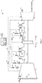
- FIG. 1 illustrates an embodiment of a gas turbine system 10 with sequential combustion that may utilize the disclosed methods of controlling firing temperatures.
- the firing temperatures mentioned above may be determined directly via measuring, determined via a model, and/or determined via a relationship with respect to metal temperature of the gas turbine system 10 parts and/or part lifetime.
- the gas turbine system 10 includes a compressor 12, a first combustor 14 (e.g., environmental (EV) combustor), a first turbine 16, a second combustor 18 (e.g., sequential environmental (SEV) combustor), and a second turbine 20.
- a first combustor 14 e.g., environmental (EV) combustor
- first turbine 16 e.g., a second combustor 18
- SEV sequential environmental
- the gas turbine system 10 may include a generator coupled to a shaft 22. In some embodiments, the gas turbine system 10 may be coupled to a different load via the shaft 22.
- a fuel, gas, or oil e.g., natural gas
- fuel line 24 may be controlled via a first fuel valve 25. Hot gases from combustion of the air fuel mixture in the first combustor 14 are partially expanded in the first turbine 16 and force turbine blades of the first turbine 16 to rotate the shaft 22. As the shaft 22 rotates, blades within the compressor 12 also rotate, thereby compressing oxidant (e.g., compressed air 23) through the compressor 12.
- oxidant e.g., compressed air 23
- the second combustor 18 may begin operation.
- additional fuel via a fuel line 26, may be added to gases in burners 28 of the second combustor 18, and combusted in the second combustor 18.
- fuel flow in the fuel line 26 may be controlled via a second fuel valve 27.
- combusted gases exiting the second combustor 18 expand in the second turbine 20, and force turbine blades of the second turbine 20 to rotate, thereby exerting torque on the shaft 22.
- exhaust gases of the gas turbine system 10 may be fed to a heat recovery steam generator and/or a waste heat boiler of a combined cycle power plant and/or another waste heat application.
- the compressor 12 may have at least one row of variable inlet guide vanes (IGV) 30.
- IGV 30 may be upstream 6 of both the first combustor 14 and the second combustor 18.
- closed air mass flows and operation pressures throughout the gas turbine system 10 may decrease.
- the minimum position of the IGV 30 e.g., the most closed position
- some of the compressed air 23 may be tapped off and used as high pressure cooling air 32, recooled via a high pressure cooling air cooler 34 and fed as high pressure cooling air 32 to the first combustor 14 and to the first turbine 16.
- the mass flow of the high pressure cooling air 32 may be controlled by a high pressure cooling air control valve 36. Additionally, or in the alternative, there may be one or more valves to control individual feeds of high pressure cooling air 32 to the first combustor 14 and to the first turbine 16.
- Some of the highpressure cooling air 32 may be fed as carrier air 37 to burners 28 of the second combustor 18.
- the mass flow of the carrier air 37 may be controlled by a carrier air control valve 38.
- Some partially compressed air from the compressor 12 may be recooled via a low pressure cooling air cooler 40 and fed as low pressure cooling air 42 to the second combustor 18 and to the second turbine 20.
- the mass flow of low pressure cooling air 42 may be controlled via a low pressure cooling air control valve 44. Additionally, or in the alternative, there may be one or more valves to control individual feeds of low pressure cooling air 42 to the second combustor 18 and to the second turbine 20.
- Partially compressed cooling air 43 may also be tapped off from the compressor 12 and routed to the second turbine 20 to cool components of the second turbine 20. Cooling air 43 may be controlled via a cooling air control valve 45.
- a controller 46 e.g., a computer-based controller
- the micro-processor 48 may be any general purpose or application-specific processor.
- the memory 50 may include one or more tangible, non-transitory, machine-readable media.
- machine-readable media can include RAM, ROM, EPROM, EEPROM, CD-ROM, or other optical disk storage, magnetic disk storage or other magnetic storage devices, or any other medium which can be used to carry or store desired program code in the form of machine-executable instructions or data structures and which can be accessed by a processor (e.g., the micro-processor 48) or by any general purpose or special purpose computer or other machine with a processor (e.g., the micro-processor 48).
- a processor e.g., the micro-processor 48
- any general purpose or special purpose computer or other machine with a processor e.g., the micro-processor 48.
- the controller 46 may also be configured to receive signals (e.g., inputs) from one or more sensors 52 indicating various parameters of the system 10.
- the one or more sensors 52 may measure and send as a signal to the controller absolute or relative gas turbine 10 load, absolute or relative power plant load, compressor 12 air mass flow, position of the IGV 30, compressor 12 discharge pressure, combustor 14, 18 inlet and outlet pressures, turbine 16, 20 inlet and outlet pressures, cooling air 32, 42, 43 mass flow, cooling air 32, 42, 43 pressure and/or temperature, hot gas path temperatures, total or partial fuel flow, number of burners 28 in operation (or switched-off), ambient conditions (e.g., temperature, pressure, and/or humidity), combustion pulsation, and other relevant parameters.
- signals e.g., inputs
- the one or more sensors 52 may measure and send as a signal to the controller absolute or relative gas turbine 10 load, absolute or relative power plant load, compressor 12 air mass flow, position of the IGV 30, compressor 12 discharge pressure, combustor 14, 18 inlet and outlet
- the sensors 52 may also be configured to measure and send as a signal (e.g., input) to the controller 46 temperature and/or pressure within a steam cycle, hot gas path temperatures, inlet air flow within the gas turbine system 10, fuel flow to the second combustor 18, exhaust air flow within the gas turbine system 10, cooling air flow within the gas turbine system 10, combustion pulsation, carbon monoxide (CO) emissions, and/or nitrous oxide (NO x ) emissions.
- the one or more sensors 52 may be acoustic sensors, automotive sensors, chemical sensors, electric/magnetic sensors, environmental sensors, optical sensors, mechanical sensors, thermal/temperature sensors, proximity sensors, and/or any other relevant form of measurement device for the above parameters.
- controller 46 may be coupled to one or more input/output devices 54 (e.g., mouse, keyboard, monitor, touch screen, network communication circuitry, speaker, microphone, toggles, switches, dials). More specifically, input devices 54 may in the form of a mouse, microphone, switches, touch screen, or any combination thereof.
- input devices 54 may in the form of a mouse, microphone, switches, touch screen, or any combination thereof.
- an operator may send a signal via the input device 54 to adjust firing temperatures of the burners 28. This may take the form of altering (e.g., limiting) fuel flow to the burners 28, switching on or off one or more burners 28, or adjusting any other relevant parameter that would alter the firing temperature of the burners 28.
- the controller 46 may contain instructions to adjust the firing temperature of the burners 28 based on a limiting firing temperature or a firing temperature schedule without operator input. Further, it should be noted that, although not shown, the controller 46 may be coupled to all of the elements in FIGS. 1-2 (e.g., burners 28, IGV 30, valves, sensors 52, combustors 14, 18, fuel lines, air lines, etc.), and may be configured to control all of the elements of FIGS. 1-2 .
- the controller 46 may determine an operational point to begin operating the gas turbine system 10 in the low part load (LPL) mode based at least on an operational parameter.
- the operational parameter may include, for example, one or more of a position of the inlet guide vanes 30, a fuel flow to an SEV combustor (e.g., second combustor 18), a temperature within a steam cycle, a pressure within a steam cycle, an inlet air flow within the gas turbine system, an exhaust air flow within the gas turbine system 10, cooling air flow within the gas turbine 10, combustion pulsation, hot gas path temperatures, carbon monoxide emissions, or nitrous oxide emissions.
- SEV combustor e.g., second combustor 18
- individual burners 28 are switched on/off in order to keep relevant gas turbine and plant parameters within acceptable operational limits for efficient and robust operation.
- individual burners of the burners 28 may be switched on/off according to operational limits that may include one or more of a temperature within the steam cycle, a fuel flow to an SEV combustor (e.g., second combustor 18), pressure within the steam cycle, inlet or exhaust air flow within the gas turbine system 10, cooling air flow within the gas turbine system 10, hot gas path temperatures, a position of the inlet guide vanes 30, combustion pulsation, and/or nitrous oxide emissions.
- operational limits may include one or more of a temperature within the steam cycle, a fuel flow to an SEV combustor (e.g., second combustor 18), pressure within the steam cycle, inlet or exhaust air flow within the gas turbine system 10, cooling air flow within the gas turbine system 10, hot gas path temperatures, a position of the inlet guide vanes 30, combustion pulsation, and/or nitrous oxide emissions.
- the operational limits and relevant gas turbine and plant parameters may include temperatures within a steam cycle, which may depend upon exhaust temperatures and pressures within the gas turbine system 10, which in turn may depend on firing temperatures and pressures within the gas turbine system 10.
- a limiting firing temperature for switched-on burners 28 may be utilized in controlling the gas turbine system 10 during LPL mode with respect to certain operational limits (e.g., a maximum acceptable firing temperature considering a metal temperature of turbine parts, a lifetime of turbine parts, a maximum allowable firing temperature for nitrous oxide emissions, a minimum firing temperature to limit carbon monoxide emissions, and a minimum temperature for steam cycle operability).
- the limiting firing temperature may be controlled (e.g., to keep the firing temperature of burners 28 at or below a specific value, or within a specific range) via controller 46 to keep the firing temperature of burners 28 within operational limitations such as maximum allowable firing temperature considering temperature of turbine parts, maximum allowable firing temperature for nitrous oxide emissions, minimum firing temperature allowable for low carbon monoxide emissions, and/or minimum firing temperature for steam cycle operability.
- the limiting firing temperature may be dependent on a parameter that represents the above operational limitations.
- the parameter may include, but is not limited to, absolute or relative gas turbine 10 load, absolute or relative plant load, compressor 12 air mass flow, position of the inlet guide vanes 30 (IGV), compressor 12 discharge, combustor 14, 18 inlet and outlet pressure, turbine 16, 20 inlet and outlet pressure, cooling air mass flow, cooling air pressure, cooling air temperature, combustion pulsation, hot gas path temperatures, total fuel flow, partial fuel flow, number of burners 28 in operation (e.g., switched-on), number of burners not in operation (e.g., switched-off), ambient temperature, ambient pressure, and/or ambient humidity.+
- blower 56 e.g., external blower
- hot gas parts e.g., first combustor 14, first turbine 16, burners 28, second combustor 18, and second turbine 20
- main gas path e.g., via high pressure cooling air 32 and low pressure cooling air 42.
- IGV in low part load operation, when the IGV are closed, air mass flows and operation pressures throughout the gas turbine system 10 may decrease.
- LPL mode switches off individual burners 28 when the gas turbine system 10 is deloading thereby keeping the firing temperature of switched-on burners 28 at a high level thereby limiting CO emissions (e.g., through sufficient burn out of fuel in the second combustor 18).
- LPL mode effectively concentrates fuel to less burners 28 (e.g., by switching-off burners 28), thus keeping the flame temperature high.
- the blower 56 may provide additional external cooling air 58 during low part load (LPL) mode when the inlet guide vanes 30 (IGV) are more closed relative to their regular operation position.
- the blower 56 may provide external cooling air 58 when the IGV 30 are in a closed position.
- the blower 56 may be coupled to cooling air 43 supply lines to provide additional external cooling air 58 to the gas turbine system 10 during low part load operation.
- the blower 56 may first receive filtered air 60 from an air filter 62.
- External cooling air 58 flow may be controlled via external cooling air valve 64.
- external cooling air valve 64 may be open while cooling air control valve 45 may be closed.
- the cooling air systems e.g., low pressure cooling air 42, high pressure cooling air 32, and/or cooling air 43
- the pressure ratio may be based off associated parameters (e.g., IGV 30 position, temperature of elements, etc.). Utilizing the blower 56 during LPL mode may provide for a further decrease in minimum load by further closing the IGV 30 (e.g., further closed from a position of -50 degrees), switching off more burners (e.g. 18 to 22 burners out of 24 burners). It may be appreciated that the operation of the blower 56 and valves 45, 64 may be controlled via controller 46. In some embodiments, the controller may cause a cooling air flow to be provided from a steam injection system and/or an internal source of the gas turbine system 10.
- the controller may cause a cooling air flow to be provided from a steam injection system and/or an internal source of the gas turbine system 10.
- FIG. 3 illustrates an embodiment of a firing temperature schedule 70 (e.g., determined via scheduling algorithms) that may be utilized with the gas turbine system 10 of FIGS. 1 and/or 2.
- the y axis 66 may be representative of a firing temperature of burners 28.
- the x axis 68 may be representative of a position of inlet guide vanes (IGV). For example, a position of the IGV may be more closed on the x axis 68 as it approaches the y axis 66.
- Tfireburner is defined as the limiting firing temperature for burners 28 in operation
- Tfire_avg is the average firing temperature for all burners 28 (e.g., switched-on and switched-off burners).
- the limiting firing temperature is interpolated as an oblique line with respect to a position of the IGV.
- a limiting firing temperature schedule may be obtained via experimentation, interpolation of data points, a pressure ratio, and/or a calculated energy balance of the combustible and the oxidant within a burner.
- the firing temperature schedule 70 e.g., limiting firing temperature
- the firing temperature schedule 70 may be with respect to an absolute or relative gas turbine 10 load, an absolute or relative power plant load, compressor 12 air mass flow, compressor 12 discharge pressure, combustor 14, 18 inlet and outlet pressures, turbine 16, 20 inlet and outlet pressures, cooling air mass flow, cooling air pressure, cooling air temperature, hot gas path temperature, total or partial fuel flow, number of burners 28 in operation or switched-off, ambient temperature, combustion pulsation, emissions, ambient pressure, and/or ambient humidity.
- the operation range is limited by a minimum acceptable position (e.g., a most closed position) of the IGV 30.
- the minimum acceptable position of the IGV 30 may depend on compressor characteristics, cooling requirements, and a minimum number of burners 28 to be operated (e.g., switched-on) in order to keep combustion stable.
- a minimum load 72 e.g., minimum firing temperature relative to the minimum acceptable position of the IGV 30
- MEL minimum environmental load
- Controller stability is the ability of the controller to 46 to keep a limit (e.g., firing temperature) constant via a fuel flow control valve. For example, at low fuel flow rates, small movements of the fuel flow control valve may lead to large temperature changes.
- the firing temperature schedule 70 may be utilized to determine an optimum control of the firing temperature (e.g., maximum firing temperature) for maximizing efficiency in the gas turbine system 10 with respect to one or more parameters (e.g., a temperature within a steam cycle, a fuel flow to an SEV combustor (e.g., second combustor 18), a pressure within a steam cycle, an inlet air flow within the gas turbine system, an exhaust air flow within the gas turbine system, hot gas path temperatures, a cooling air flow within the gas turbine, a position of the inlet guide vanes 30, carbon monoxide emissions, and/or nitrous oxide emissions) that may represent operational limits.
- parameters e.g., a temperature within a steam cycle, a fuel flow to an SEV combustor (e.g., second combustor 18), a pressure within a steam cycle, an inlet air flow within the gas turbine system, an exhaust air flow within the gas turbine system, hot gas path temperatures, a cooling air flow within the gas turbine, a position of
- FIG. 4 illustrates an embodiment of the firing temperature of the gas turbine engine 10 of FIGS. 1 and 2 with respect to engine load.
- the y axis 76 represents a firing temperature of the burners 28 and the x axis 78 represents an engine load of the gas turbine system 10.
- the firing temperature may depend on operational limits which may include maximum acceptable firing temperature for turbine parts 80 (e.g., part lifetime), maximum allowable firing temperature for nitrous oxide emissions 82 (e.g., NO x ), minimum firing temperature allowable for low carbon monoxide emissions 84 (e.g., CO), and minimum firing temperature for steam cycle operability 86 (e.g., steam temperature).
- the firing temperature may be controlled via the limiting firing temperature (e.g., limited by the operational limits) to maximize the firing temperature as allowed by the operational limits illustrated in the current embodiment.
- the firing temperature may be controlled to lie on line 88 that may be representative of a limiting firing temperature.
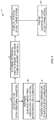
- FIG. 5 illustrates a flow chart of an embodiment of a method 90 for controlling a gas turbine system.
- a controller may receive one or more operational parameters from one or more sensors.
- the one or more parameters may include, but are not limited to a position of inlet guide vanes, an absolute or relative gas turbine load, an absolute or relative power plant load, compressor air mass flow, compressor discharge pressure, combustor inlet and outlet pressures, turbine inlet and outlet pressures, cooling air mass flow, cooling air pressure, cooling air temperature, hot gas path temperature, total or partial fuel flow, number of burners in operation of switched-off, ambient temperature, ambient pressure, ambient humidity, a fuel flow to an SEV combustor (e.g., second combustor 18), temperature within a steam cycle, pressure within a steam cycle, hot gas path temperatures, inlet air flow within the gas turbine system, exhaust air flow within the gas turbine system, cooling air flow within the gas turbine, combustion pulsation, carbon monoxide emissions, and/or nitrous oxide emissions.
- the controller may determine a schedule and/or a limiting firing temperature at which to operate burners of a sequential environmental (SEV) combustor (e.g., second combustor).
- the limiting firing temperature and/or schedule may be based on one or more parameters, which may include a position of the inlet guide vanes 30 (IGV), an absolute or relative gas turbine load, an absolute or relative power plant load, compressor air mass flow, compressor discharge pressure, combustor inlet and outlet pressures, turbine inlet and outlet pressures, cooling air mass flow, cooling air pressure, cooling air temperature, hot gas path temperature, total or partial fuel flow, number of burners of the plurality of burners in operation or switched-off, ambient temperature, ambient pressure, or ambient humidity.
- IGV position of the inlet guide vanes 30
- the limiting firing temperature and/or schedule may be restricted by operational limitations which may include a maximum acceptable firing temperature considering a metal temperature of parts of the gas turbine system, a maximum allowable firing temperature for nitrous oxide emissions, a minimum firing temperature to limit carbon monoxide emissions, and a minimum temperature for steam cycle operability.
- the controller may control the firing temperature of burners of the SEV combustor to follow the schedule, to be at or below the limiting firing temperature, and/or to be within a specific range (e.g., within the operational limitations mentioned above).
- the controller may determine an operational point to operate the gas turbine system in low part load (LPL) operation.
- the operational point may be determined based on the one or more parameters that were received as inputs from the one or more sensors. For example, operational point may be based on a position of the IGV 30, a fuel flow to an SEV combustor (e.g., second combustor 18), a temperature within a steam cycle, pressure within a steam cycle, inlet air flow within the gas turbine system 10, exhaust air flow within the gas turbine system 10, hot gas path temperatures, cooling air flow within the gas turbine system 10, combustion pulsation, carbon monoxide emissions, or nitrous oxide emissions, or any combination thereof.
- SEV combustor e.g., second combustor 18
- individual burners of the SEV combustor may be switched off as a load of the gas turbine system decreases.
- operations in blocks 94 and 96 may be performed in conjunction with operations in block 98.
- the controller may start LPL mode of the turbine system based at least in part on reaching the operational point determined at block 98. Furthermore, in some embodiments, when the gas turbine system is in LPL operation, additional airflow may be provided to the gas turbine system at block 102. In some embodiments, the additional airflow may be provided from an external blower. In some embodiments, the additional airflow may be provided via steam injection system and/or may be provided via an internal source of the gas turbine engine.
- Technical effects of the invention include enhancing the precision at which the gas turbine firing temperature and its associated parameters (e.g., gas turbine outlet temperature and/or conditions within the downstream steam cycle) are controlled.
- current embodiments provide for controlling the gas turbine system in narrow combustor operational windows to reach lower environmentally compliant loads, and supporting mechanical integrity of the turbine engine and plant components, which may be limited by a maximum temperature.
- enhancing the control precision provides for more burners of the sequential environment (SEV) combustor to be switched-off, and provides for a potential to increase an operation range by 5 to 10 percent of the nominal load. Accordingly, the reduction of minimum load may enhance load flexibility and reduce fuel consumption when electricity demand is temporarily low.
- SEV sequential environment
- operating the plant closer to a burner limiting firing temperature may increase the efficiency of low part load mode as well as increase efficiency of the turbine system in general.
- environmental benefits may include increased precision in control of pollutant emissions, and a reduction of greenhouse gas emissions due to the increase of efficiency.
Landscapes
- Engineering & Computer Science (AREA)
- Chemical & Material Sciences (AREA)
- Combustion & Propulsion (AREA)
- Mechanical Engineering (AREA)
- General Engineering & Computer Science (AREA)
- Control Of Turbines (AREA)
Applications Claiming Priority (1)
| Application Number | Priority Date | Filing Date | Title |
|---|---|---|---|
| US201714458912A | 2017-03-14 | 2017-03-14 |
Publications (2)
| Publication Number | Publication Date |
|---|---|
| EP3376003A1 true EP3376003A1 (de) | 2018-09-19 |
| EP3376003B1 EP3376003B1 (de) | 2020-04-29 |
Family
ID=61599012
Family Applications (1)
| Application Number | Title | Priority Date | Filing Date |
|---|---|---|---|
| EP18160629.4A Active EP3376003B1 (de) | 2017-03-14 | 2018-03-08 | Verfahren und system zur steuerung eines sequentiellen gasturbinenmotors |
Country Status (2)
| Country | Link |
|---|---|
| EP (1) | EP3376003B1 (de) |
| HU (1) | HUE050483T2 (de) |
Cited By (3)
| Publication number | Priority date | Publication date | Assignee | Title |
|---|---|---|---|---|
| CN112344370A (zh) * | 2019-08-08 | 2021-02-09 | 安萨尔多能源瑞士股份公司 | 用于燃气涡轮组件的顺序燃烧器组件及其运行方法 |
| CN112344369A (zh) * | 2019-08-08 | 2021-02-09 | 安萨尔多能源瑞士股份公司 | 包括顺序燃烧器的燃气涡轮组件及其运行方法 |
| EP3845813A1 (de) * | 2019-12-31 | 2021-07-07 | Ansaldo Energia Switzerland AG | Verfahren zum betrieb einer gasturbinenanordnung und gasturbinenanordnung |
Citations (4)
| Publication number | Priority date | Publication date | Assignee | Title |
|---|---|---|---|---|
| EP2600063A2 (de) * | 2013-02-19 | 2013-06-05 | Alstom Technology Ltd | Verfahren zum Betrieb einer Gasturbine mit gestufter und/oder sequentieller Verbrennung |
| US20130219904A1 (en) * | 2009-04-01 | 2013-08-29 | Alstom Technology Ltd. | Methods of Operation of A Gas Turbine With Improved Part Load Emissions Behavior |
| EP2700879A2 (de) * | 2012-08-24 | 2014-02-26 | Alstom Technology Ltd | Verfahren zum Mischen einer Verdünnungsluft in einem sequenziellen Verbrennungssystem einer Gasturbine |
| EP3037726A1 (de) * | 2014-12-22 | 2016-06-29 | Alstom Technology Ltd | Getrennte Zufuhr von Kühlungs- und Verdünnungsluft |
-
2018
- 2018-03-08 HU HUE18160629A patent/HUE050483T2/hu unknown
- 2018-03-08 EP EP18160629.4A patent/EP3376003B1/de active Active
Patent Citations (4)
| Publication number | Priority date | Publication date | Assignee | Title |
|---|---|---|---|---|
| US20130219904A1 (en) * | 2009-04-01 | 2013-08-29 | Alstom Technology Ltd. | Methods of Operation of A Gas Turbine With Improved Part Load Emissions Behavior |
| EP2700879A2 (de) * | 2012-08-24 | 2014-02-26 | Alstom Technology Ltd | Verfahren zum Mischen einer Verdünnungsluft in einem sequenziellen Verbrennungssystem einer Gasturbine |
| EP2600063A2 (de) * | 2013-02-19 | 2013-06-05 | Alstom Technology Ltd | Verfahren zum Betrieb einer Gasturbine mit gestufter und/oder sequentieller Verbrennung |
| EP3037726A1 (de) * | 2014-12-22 | 2016-06-29 | Alstom Technology Ltd | Getrennte Zufuhr von Kühlungs- und Verdünnungsluft |
Cited By (7)
| Publication number | Priority date | Publication date | Assignee | Title |
|---|---|---|---|---|
| CN112344370A (zh) * | 2019-08-08 | 2021-02-09 | 安萨尔多能源瑞士股份公司 | 用于燃气涡轮组件的顺序燃烧器组件及其运行方法 |
| CN112344369A (zh) * | 2019-08-08 | 2021-02-09 | 安萨尔多能源瑞士股份公司 | 包括顺序燃烧器的燃气涡轮组件及其运行方法 |
| EP3772615A1 (de) * | 2019-08-08 | 2021-02-10 | Ansaldo Energia Switzerland AG | Sequenzielle brennkammeranordnung für eine gasturbinenanordnung und verfahren zum betreiben dieser sequentiellen brennkammeranordnung |
| EP3772616A1 (de) * | 2019-08-08 | 2021-02-10 | Ansaldo Energia Switzerland AG | Gasturbinenanordnung mit sequentieller brennkammer und verfahren zum betreiben dieser gasturbinenanordnung |
| CN112344370B (zh) * | 2019-08-08 | 2024-10-22 | 安萨尔多能源瑞士股份公司 | 用于燃气涡轮组件的顺序燃烧器组件及其运行方法 |
| EP3845813A1 (de) * | 2019-12-31 | 2021-07-07 | Ansaldo Energia Switzerland AG | Verfahren zum betrieb einer gasturbinenanordnung und gasturbinenanordnung |
| CN113123870A (zh) * | 2019-12-31 | 2021-07-16 | 安萨尔多能源瑞士股份公司 | 用于操作燃气涡轮组件的方法和燃气涡轮组件 |
Also Published As
| Publication number | Publication date |
|---|---|
| HUE050483T2 (hu) | 2020-12-28 |
| EP3376003B1 (de) | 2020-04-29 |
Similar Documents
| Publication | Publication Date | Title |
|---|---|---|
| US11092085B2 (en) | Method and system for controlling a sequential gas turbine engine | |
| JP5789266B2 (ja) | 排気温度対タービン圧力比に基づくタービン制御方法および装置 | |
| US10544739B2 (en) | Method and apparatus for optimizing the operation of a turbine system under flexible loads | |
| RU2540210C2 (ru) | Способ управления режимом работы газовой турбины на основе температуры выхлопного газа и газовая турбина | |
| RU2542617C2 (ru) | Порог на основе температуры выхлопного газа для способа управления турбиной и турбина | |
| CN104981663B (zh) | 操作具有分级和/或连续燃烧的燃气涡轮的方法 | |
| US20140150438A1 (en) | System and method for operating a gas turbine in a turndown mode | |
| RU2539930C2 (ru) | Способ управления режимом работы газовой турбины на основе температуры выхлопного газа и газовая турбина | |
| US10669959B2 (en) | Control device, system, control method, power control device, gas turbine, and power control method | |
| EP3376003B1 (de) | Verfahren und system zur steuerung eines sequentiellen gasturbinenmotors | |
| EP3147485B1 (de) | Transiente emissionstemperatursteuerung eines turbinensystems | |
| EP3845813B1 (de) | Verfahren zum betrieb einer gasturbinenanordnung und gasturbinenanordnung |
Legal Events
| Date | Code | Title | Description |
|---|---|---|---|
| PUAI | Public reference made under article 153(3) epc to a published international application that has entered the european phase |
Free format text: ORIGINAL CODE: 0009012 |
|
| STAA | Information on the status of an ep patent application or granted ep patent |
Free format text: STATUS: THE APPLICATION HAS BEEN PUBLISHED |
|
| AK | Designated contracting states |
Kind code of ref document: A1 Designated state(s): AL AT BE BG CH CY CZ DE DK EE ES FI FR GB GR HR HU IE IS IT LI LT LU LV MC MK MT NL NO PL PT RO RS SE SI SK SM TR |
|
| AX | Request for extension of the european patent |
Extension state: BA ME |
|
| STAA | Information on the status of an ep patent application or granted ep patent |
Free format text: STATUS: REQUEST FOR EXAMINATION WAS MADE |
|
| 17P | Request for examination filed |
Effective date: 20190319 |
|
| RBV | Designated contracting states (corrected) |
Designated state(s): AL AT BE BG CH CY CZ DE DK EE ES FI FR GB GR HR HU IE IS IT LI LT LU LV MC MK MT NL NO PL PT RO RS SE SI SK SM TR |
|
| RIC1 | Information provided on ipc code assigned before grant |
Ipc: F23C 6/04 20060101ALI20190919BHEP Ipc: F01K 23/10 20060101ALI20190919BHEP Ipc: F02C 6/18 20060101AFI20190919BHEP Ipc: F23N 1/02 20060101ALI20190919BHEP Ipc: F23R 3/34 20060101ALI20190919BHEP |
|
| GRAP | Despatch of communication of intention to grant a patent |
Free format text: ORIGINAL CODE: EPIDOSNIGR1 |
|
| STAA | Information on the status of an ep patent application or granted ep patent |
Free format text: STATUS: GRANT OF PATENT IS INTENDED |
|
| INTG | Intention to grant announced |
Effective date: 20191105 |
|
| GRAS | Grant fee paid |
Free format text: ORIGINAL CODE: EPIDOSNIGR3 |
|
| GRAA | (expected) grant |
Free format text: ORIGINAL CODE: 0009210 |
|
| STAA | Information on the status of an ep patent application or granted ep patent |
Free format text: STATUS: THE PATENT HAS BEEN GRANTED |
|
| AK | Designated contracting states |
Kind code of ref document: B1 Designated state(s): AL AT BE BG CH CY CZ DE DK EE ES FI FR GB GR HR HU IE IS IT LI LT LU LV MC MK MT NL NO PL PT RO RS SE SI SK SM TR |
|
| REG | Reference to a national code |
Ref country code: GB Ref legal event code: FG4D |
|
| REG | Reference to a national code |
Ref country code: CH Ref legal event code: EP |
|
| REG | Reference to a national code |
Ref country code: AT Ref legal event code: REF Ref document number: 1263669 Country of ref document: AT Kind code of ref document: T Effective date: 20200515 |
|
| REG | Reference to a national code |
Ref country code: DE Ref legal event code: R096 Ref document number: 602018004066 Country of ref document: DE |
|
| REG | Reference to a national code |
Ref country code: IE Ref legal event code: FG4D |
|
| REG | Reference to a national code |
Ref country code: NL Ref legal event code: MP Effective date: 20200429 |
|
| REG | Reference to a national code |
Ref country code: LT Ref legal event code: MG4D |
|
| PG25 | Lapsed in a contracting state [announced via postgrant information from national office to epo] |
Ref country code: PT Free format text: LAPSE BECAUSE OF FAILURE TO SUBMIT A TRANSLATION OF THE DESCRIPTION OR TO PAY THE FEE WITHIN THE PRESCRIBED TIME-LIMIT Effective date: 20200831 Ref country code: IS Free format text: LAPSE BECAUSE OF FAILURE TO SUBMIT A TRANSLATION OF THE DESCRIPTION OR TO PAY THE FEE WITHIN THE PRESCRIBED TIME-LIMIT Effective date: 20200829 Ref country code: LT Free format text: LAPSE BECAUSE OF FAILURE TO SUBMIT A TRANSLATION OF THE DESCRIPTION OR TO PAY THE FEE WITHIN THE PRESCRIBED TIME-LIMIT Effective date: 20200429 Ref country code: SE Free format text: LAPSE BECAUSE OF FAILURE TO SUBMIT A TRANSLATION OF THE DESCRIPTION OR TO PAY THE FEE WITHIN THE PRESCRIBED TIME-LIMIT Effective date: 20200429 Ref country code: NO Free format text: LAPSE BECAUSE OF FAILURE TO SUBMIT A TRANSLATION OF THE DESCRIPTION OR TO PAY THE FEE WITHIN THE PRESCRIBED TIME-LIMIT Effective date: 20200729 Ref country code: FI Free format text: LAPSE BECAUSE OF FAILURE TO SUBMIT A TRANSLATION OF THE DESCRIPTION OR TO PAY THE FEE WITHIN THE PRESCRIBED TIME-LIMIT Effective date: 20200429 Ref country code: GR Free format text: LAPSE BECAUSE OF FAILURE TO SUBMIT A TRANSLATION OF THE DESCRIPTION OR TO PAY THE FEE WITHIN THE PRESCRIBED TIME-LIMIT Effective date: 20200730 |
|
| REG | Reference to a national code |
Ref country code: AT Ref legal event code: MK05 Ref document number: 1263669 Country of ref document: AT Kind code of ref document: T Effective date: 20200429 |
|
| PG25 | Lapsed in a contracting state [announced via postgrant information from national office to epo] |
Ref country code: HR Free format text: LAPSE BECAUSE OF FAILURE TO SUBMIT A TRANSLATION OF THE DESCRIPTION OR TO PAY THE FEE WITHIN THE PRESCRIBED TIME-LIMIT Effective date: 20200429 Ref country code: LV Free format text: LAPSE BECAUSE OF FAILURE TO SUBMIT A TRANSLATION OF THE DESCRIPTION OR TO PAY THE FEE WITHIN THE PRESCRIBED TIME-LIMIT Effective date: 20200429 Ref country code: BG Free format text: LAPSE BECAUSE OF FAILURE TO SUBMIT A TRANSLATION OF THE DESCRIPTION OR TO PAY THE FEE WITHIN THE PRESCRIBED TIME-LIMIT Effective date: 20200729 Ref country code: RS Free format text: LAPSE BECAUSE OF FAILURE TO SUBMIT A TRANSLATION OF THE DESCRIPTION OR TO PAY THE FEE WITHIN THE PRESCRIBED TIME-LIMIT Effective date: 20200429 |
|
| REG | Reference to a national code |
Ref country code: HU Ref legal event code: AG4A Ref document number: E050483 Country of ref document: HU |
|
| PG25 | Lapsed in a contracting state [announced via postgrant information from national office to epo] |
Ref country code: AL Free format text: LAPSE BECAUSE OF FAILURE TO SUBMIT A TRANSLATION OF THE DESCRIPTION OR TO PAY THE FEE WITHIN THE PRESCRIBED TIME-LIMIT Effective date: 20200429 Ref country code: NL Free format text: LAPSE BECAUSE OF FAILURE TO SUBMIT A TRANSLATION OF THE DESCRIPTION OR TO PAY THE FEE WITHIN THE PRESCRIBED TIME-LIMIT Effective date: 20200429 |
|
| PG25 | Lapsed in a contracting state [announced via postgrant information from national office to epo] |
Ref country code: DK Free format text: LAPSE BECAUSE OF FAILURE TO SUBMIT A TRANSLATION OF THE DESCRIPTION OR TO PAY THE FEE WITHIN THE PRESCRIBED TIME-LIMIT Effective date: 20200429 Ref country code: ES Free format text: LAPSE BECAUSE OF FAILURE TO SUBMIT A TRANSLATION OF THE DESCRIPTION OR TO PAY THE FEE WITHIN THE PRESCRIBED TIME-LIMIT Effective date: 20200429 Ref country code: CZ Free format text: LAPSE BECAUSE OF FAILURE TO SUBMIT A TRANSLATION OF THE DESCRIPTION OR TO PAY THE FEE WITHIN THE PRESCRIBED TIME-LIMIT Effective date: 20200429 Ref country code: RO Free format text: LAPSE BECAUSE OF FAILURE TO SUBMIT A TRANSLATION OF THE DESCRIPTION OR TO PAY THE FEE WITHIN THE PRESCRIBED TIME-LIMIT Effective date: 20200429 Ref country code: AT Free format text: LAPSE BECAUSE OF FAILURE TO SUBMIT A TRANSLATION OF THE DESCRIPTION OR TO PAY THE FEE WITHIN THE PRESCRIBED TIME-LIMIT Effective date: 20200429 Ref country code: EE Free format text: LAPSE BECAUSE OF FAILURE TO SUBMIT A TRANSLATION OF THE DESCRIPTION OR TO PAY THE FEE WITHIN THE PRESCRIBED TIME-LIMIT Effective date: 20200429 Ref country code: SM Free format text: LAPSE BECAUSE OF FAILURE TO SUBMIT A TRANSLATION OF THE DESCRIPTION OR TO PAY THE FEE WITHIN THE PRESCRIBED TIME-LIMIT Effective date: 20200429 |
|
| REG | Reference to a national code |
Ref country code: DE Ref legal event code: R097 Ref document number: 602018004066 Country of ref document: DE |
|
| PG25 | Lapsed in a contracting state [announced via postgrant information from national office to epo] |
Ref country code: PL Free format text: LAPSE BECAUSE OF FAILURE TO SUBMIT A TRANSLATION OF THE DESCRIPTION OR TO PAY THE FEE WITHIN THE PRESCRIBED TIME-LIMIT Effective date: 20200429 Ref country code: SK Free format text: LAPSE BECAUSE OF FAILURE TO SUBMIT A TRANSLATION OF THE DESCRIPTION OR TO PAY THE FEE WITHIN THE PRESCRIBED TIME-LIMIT Effective date: 20200429 |
|
| PLBE | No opposition filed within time limit |
Free format text: ORIGINAL CODE: 0009261 |
|
| STAA | Information on the status of an ep patent application or granted ep patent |
Free format text: STATUS: NO OPPOSITION FILED WITHIN TIME LIMIT |
|
| 26N | No opposition filed |
Effective date: 20210201 |
|
| PG25 | Lapsed in a contracting state [announced via postgrant information from national office to epo] |
Ref country code: SI Free format text: LAPSE BECAUSE OF FAILURE TO SUBMIT A TRANSLATION OF THE DESCRIPTION OR TO PAY THE FEE WITHIN THE PRESCRIBED TIME-LIMIT Effective date: 20200429 |
|
| PG25 | Lapsed in a contracting state [announced via postgrant information from national office to epo] |
Ref country code: MC Free format text: LAPSE BECAUSE OF FAILURE TO SUBMIT A TRANSLATION OF THE DESCRIPTION OR TO PAY THE FEE WITHIN THE PRESCRIBED TIME-LIMIT Effective date: 20200429 |
|
| REG | Reference to a national code |
Ref country code: BE Ref legal event code: MM Effective date: 20210331 |
|
| PG25 | Lapsed in a contracting state [announced via postgrant information from national office to epo] |
Ref country code: LU Free format text: LAPSE BECAUSE OF NON-PAYMENT OF DUE FEES Effective date: 20210308 Ref country code: IE Free format text: LAPSE BECAUSE OF NON-PAYMENT OF DUE FEES Effective date: 20210308 |
|
| PGFP | Annual fee paid to national office [announced via postgrant information from national office to epo] |
Ref country code: HU Payment date: 20220223 Year of fee payment: 5 Ref country code: CH Payment date: 20220218 Year of fee payment: 5 |
|
| PGFP | Annual fee paid to national office [announced via postgrant information from national office to epo] |
Ref country code: FR Payment date: 20220221 Year of fee payment: 5 |
|
| PG25 | Lapsed in a contracting state [announced via postgrant information from national office to epo] |
Ref country code: BE Free format text: LAPSE BECAUSE OF NON-PAYMENT OF DUE FEES Effective date: 20210331 |
|
| P01 | Opt-out of the competence of the unified patent court (upc) registered |
Effective date: 20230522 |
|
| PG25 | Lapsed in a contracting state [announced via postgrant information from national office to epo] |
Ref country code: CY Free format text: LAPSE BECAUSE OF FAILURE TO SUBMIT A TRANSLATION OF THE DESCRIPTION OR TO PAY THE FEE WITHIN THE PRESCRIBED TIME-LIMIT Effective date: 20200429 |
|
| REG | Reference to a national code |
Ref country code: CH Ref legal event code: PL |
|
| REG | Reference to a national code |
Ref country code: DE Ref legal event code: R082 Ref document number: 602018004066 Country of ref document: DE Ref country code: DE Ref legal event code: R081 Ref document number: 602018004066 Country of ref document: DE Owner name: GENERAL ELECTRIC TECHNOLOGY GMBH, CH Free format text: FORMER OWNER: GENERAL ELECTRIC COMPANY, SCHENECTADY, NY, US |
|
| PG25 | Lapsed in a contracting state [announced via postgrant information from national office to epo] |
Ref country code: LI Free format text: LAPSE BECAUSE OF NON-PAYMENT OF DUE FEES Effective date: 20230331 Ref country code: HU Free format text: LAPSE BECAUSE OF NON-PAYMENT OF DUE FEES Effective date: 20230309 Ref country code: FR Free format text: LAPSE BECAUSE OF NON-PAYMENT OF DUE FEES Effective date: 20230331 Ref country code: CH Free format text: LAPSE BECAUSE OF NON-PAYMENT OF DUE FEES Effective date: 20230331 |
|
| REG | Reference to a national code |
Ref country code: GB Ref legal event code: 732E Free format text: REGISTERED BETWEEN 20240222 AND 20240228 |
|
| PG25 | Lapsed in a contracting state [announced via postgrant information from national office to epo] |
Ref country code: MK Free format text: LAPSE BECAUSE OF FAILURE TO SUBMIT A TRANSLATION OF THE DESCRIPTION OR TO PAY THE FEE WITHIN THE PRESCRIBED TIME-LIMIT Effective date: 20200429 |
|
| PG25 | Lapsed in a contracting state [announced via postgrant information from national office to epo] |
Ref country code: TR Free format text: LAPSE BECAUSE OF FAILURE TO SUBMIT A TRANSLATION OF THE DESCRIPTION OR TO PAY THE FEE WITHIN THE PRESCRIBED TIME-LIMIT Effective date: 20200429 |
|
| PG25 | Lapsed in a contracting state [announced via postgrant information from national office to epo] |
Ref country code: MT Free format text: LAPSE BECAUSE OF FAILURE TO SUBMIT A TRANSLATION OF THE DESCRIPTION OR TO PAY THE FEE WITHIN THE PRESCRIBED TIME-LIMIT Effective date: 20200429 |
|
| PGFP | Annual fee paid to national office [announced via postgrant information from national office to epo] |
Ref country code: DE Payment date: 20250218 Year of fee payment: 8 |
|
| PGFP | Annual fee paid to national office [announced via postgrant information from national office to epo] |
Ref country code: IT Payment date: 20250218 Year of fee payment: 8 Ref country code: GB Payment date: 20250221 Year of fee payment: 8 |