EP3375715B1 - System zum erzeugen von strom im orbit mittels schwebender leiterkabel - Google Patents
System zum erzeugen von strom im orbit mittels schwebender leiterkabel Download PDFInfo
- Publication number
- EP3375715B1 EP3375715B1 EP16863721.3A EP16863721A EP3375715B1 EP 3375715 B1 EP3375715 B1 EP 3375715B1 EP 16863721 A EP16863721 A EP 16863721A EP 3375715 B1 EP3375715 B1 EP 3375715B1
- Authority
- EP
- European Patent Office
- Prior art keywords
- tethers
- electrical power
- tether
- electrodynamic
- electrons
- Prior art date
- Legal status (The legal status is an assumption and is not a legal conclusion. Google has not performed a legal analysis and makes no representation as to the accuracy of the status listed.)
- Active
Links
Images
Classifications
-
- B—PERFORMING OPERATIONS; TRANSPORTING
- B64—AIRCRAFT; AVIATION; COSMONAUTICS
- B64G—COSMONAUTICS; VEHICLES OR EQUIPMENT THEREFOR
- B64G1/00—Cosmonautic vehicles
- B64G1/22—Parts of, or equipment specially adapted for fitting in or to, cosmonautic vehicles
- B64G1/42—Arrangements or adaptations of power supply systems
- B64G1/421—Non-solar power generation
-
- B—PERFORMING OPERATIONS; TRANSPORTING
- B64—AIRCRAFT; AVIATION; COSMONAUTICS
- B64G—COSMONAUTICS; VEHICLES OR EQUIPMENT THEREFOR
- B64G1/00—Cosmonautic vehicles
- B64G1/22—Parts of, or equipment specially adapted for fitting in or to, cosmonautic vehicles
- B64G1/42—Arrangements or adaptations of power supply systems
-
- B—PERFORMING OPERATIONS; TRANSPORTING
- B64—AIRCRAFT; AVIATION; COSMONAUTICS
- B64G—COSMONAUTICS; VEHICLES OR EQUIPMENT THEREFOR
- B64G1/00—Cosmonautic vehicles
- B64G1/22—Parts of, or equipment specially adapted for fitting in or to, cosmonautic vehicles
- B64G1/64—Systems for coupling or separating cosmonautic vehicles or parts thereof, e.g. docking arrangements
- B64G1/648—Tethers
-
- B—PERFORMING OPERATIONS; TRANSPORTING
- B64—AIRCRAFT; AVIATION; COSMONAUTICS
- B64G—COSMONAUTICS; VEHICLES OR EQUIPMENT THEREFOR
- B64G1/00—Cosmonautic vehicles
-
- B—PERFORMING OPERATIONS; TRANSPORTING
- B64—AIRCRAFT; AVIATION; COSMONAUTICS
- B64G—COSMONAUTICS; VEHICLES OR EQUIPMENT THEREFOR
- B64G1/00—Cosmonautic vehicles
- B64G1/22—Parts of, or equipment specially adapted for fitting in or to, cosmonautic vehicles
- B64G1/24—Guiding or controlling apparatus, e.g. for attitude control
- B64G1/32—Guiding or controlling apparatus, e.g. for attitude control using earth's magnetic field
-
- H—ELECTRICITY
- H01—ELECTRIC ELEMENTS
- H01B—CABLES; CONDUCTORS; INSULATORS; SELECTION OF MATERIALS FOR THEIR CONDUCTIVE, INSULATING OR DIELECTRIC PROPERTIES
- H01B1/00—Conductors or conductive bodies characterised by the conductive materials; Selection of materials as conductors
-
- H—ELECTRICITY
- H01—ELECTRIC ELEMENTS
- H01M—PROCESSES OR MEANS, e.g. BATTERIES, FOR THE DIRECT CONVERSION OF CHEMICAL ENERGY INTO ELECTRICAL ENERGY
- H01M10/00—Secondary cells; Manufacture thereof
- H01M10/42—Methods or arrangements for servicing or maintenance of secondary cells or secondary half-cells
- H01M10/46—Accumulators structurally combined with charging apparatus
-
- Y—GENERAL TAGGING OF NEW TECHNOLOGICAL DEVELOPMENTS; GENERAL TAGGING OF CROSS-SECTIONAL TECHNOLOGIES SPANNING OVER SEVERAL SECTIONS OF THE IPC; TECHNICAL SUBJECTS COVERED BY FORMER USPC CROSS-REFERENCE ART COLLECTIONS [XRACs] AND DIGESTS
- Y02—TECHNOLOGIES OR APPLICATIONS FOR MITIGATION OR ADAPTATION AGAINST CLIMATE CHANGE
- Y02E—REDUCTION OF GREENHOUSE GAS [GHG] EMISSIONS, RELATED TO ENERGY GENERATION, TRANSMISSION OR DISTRIBUTION
- Y02E60/00—Enabling technologies; Technologies with a potential or indirect contribution to GHG emissions mitigation
- Y02E60/10—Energy storage using batteries
Definitions
- the present invention belongs to the aerospace field. More particularly, it belongs to the systems for generating electrical power on board satellites. Specifically, those that use moorings or bare electrodynamic tethers as passive elements for the conversion of the orbital energy of a satellite into useful energy on board it, thanks to the electrodynamic force produced by the magnetic field of the planet upon the current carried by the tether.
- the state of the art has already dealt with the problem of generating electrical power on board satellites, being this an essential element for the lifetime of a satellite and the operations thereof.
- the most widely used system for generating electrical power is based on the photovoltaic principles, in which solar energy is converted into electric energy by means of solar panels and with the possibility of increasing the efficiency of this process with several methods (for example, using solar concentrators and cutting-edge materials).
- photovoltaic methods suffer from several limitations.
- their ability to generate electrical power depends on the amount of solar radiation received which is practically reduced to zero during eclipses, thereby forcing the satellites to store energy in batteries during the illuminated phase of each orbit.
- the electrical power received decays with the square of the distance from the Sun, which greatly reduces the applicability of this technology in space missions that go farther than Jupiter and Saturn.
- costly systems for generating electrical power based on nuclear reactions are used.
- This mechanism has been known for several decades and is based on the conversion of orbital energy into electrical energy thanks to the electrodynamic force that acts on a conducting body in movement relative to another conductive, in this particular case the ionospheric plasma and the tether, in the presence of a magnetic field [ Alfvén, H, Spacecraft propulsion: new methods, Science, New Series, Vol 176, 4031, pp 167-168, 1972 ].
- conductive tethers in the form of large thin stapes, with lengths, widths and thicknesses typical of the order of kilometres, centimetres and microns respectively, turn out to be very efficient at generating electrical power and have been studied extensively in the scientific literature [ Sanmartin, J., Martinez-Sanchez, M and Ahedo, E., Bare wire anodes for electrodynamic tethers, Journal of Propulsion and Power, Vol 9, 3, pp 353- 359, 1993 , Sanmartin, J and Estes, R.
- the intensity is maximum right at the end of the tether where the element for using or storing electrical power is connected.
- the presence of the hollow cathode introduces significant disadvantages.
- FEACs Field emission array cathodes
- thermionic emitters have been proposed that do not need gas. Currently, the electron emission capability of these devices is still far lower than the one of traditional hollow cathodes.
- a bare electrodynamic tether In the absence of an electron emission device, a bare electrodynamic tether (i.e. without electrical insulation) is not very efficient.
- the bare tether naturally exchanges charge with the plasma but, due to the large difference in mass between electrons and ions, the current that circulates through is drastically reduced.
- This is what is known as a floating electrodynamic tether (or floating electrodynamic tether), which has no current intensity at its end points and was proposed as a scientific instrument to artificially excite auroras [ Sanmart ⁇ n, J., Charro, M., Peláez, J., Tinao, I., Elaskar, S., Hilgers, A.
- C12A7:e - which shows much better emission and stability properties compared to other ceramic coatings, among which LaB 6 , CeB 6 , BaO-W, Ba-W, BaO and 12CaO-7Al 2 O 3 (C12A7:e - ) are included.
- the only way to generate electrical power in orbit by means of floating tethers is to use a system of multiple tethers (at least two) which are extended from a satellite in opposite directions with respect to the electromotive electrical field.
- This system of multiple tethers is described and analysed for the first time in this invention. It is important to emphasise that in the abstract of the article about floating tethers with thermionic emission [ Williams, J. D., Sanmart ⁇ n, J. and Rand, L. P., Low-Work function coating for entirely propellantless bare electrodynamic tether, IEEE Transactions on Plasma Science, Vol 40, 5, pp 1441-1445, 2012 ] the possibility is mentioned of using the concept to deorbit and generate electrical power. However, in the body thereof, the authors exclusively analyse the first of these applications and do not propose any system design that enables the generation of electrical power.
- FR 2809083 shows an electrodynamic propulsion system comprising a pair of opposite electrically conductive, non-isolated masts connected to two different poles of an electric power source.
- US 2012/0104176 A1 discloses an electric sail with voltage multipliers in tethers, wherein the tethers are electrically charged in order to generate thrust from solar wind.
- an original design is proposed that, for the first time, enables electrical power to be generated on board a satellite by means of the use of floating tethers, which are responsible for the capture and emission of electrons.
- the system for using or storing electrical power has two poles, each of which is electrically connected to the end of an assembly of conductive tethers, and wherein each one of the sets of conductive tethers is made up of at least one conductive tether.
- the photoelectric emission of electrons throughout the tethers is envisaged and a description is included on how the tethers must be designed to make this mechanism more efficient.
- Some materials that could facilitate photoelectric emission are the alkaline metals or the compounds Ag- CS 2 O-CS, Ag-Cs 3 Sb, and Na 2 KSb.
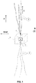
- the present invention relates to a system for generating electrical power for satellites in orbit characterised in that it comprises two sets of electrodynamic floating conductive tethers (2,3) each one respectively connected to the two poles (4,5) of a system for using or storing electrical power (6) on board a spacecraft in orbit (1).
- each set has three tethers.
- the tethers belonging to the set (2) are electrically connected to the positive pole (4) while the tethers belonging to the set (3) are electrically connected to the negative pole (5).
- a device for storing or using electrical power (6) is connected to the two poles (4) and (5).
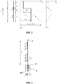
- two tethers, L 1 and L 2 are connected to a device for storing or using electrical power with impedance Z e .
- each of the tethers has a collector segment and another emitter one.
- the proposed system is suitable for generating electrical power on board a satellite in orbit around a planet equipped with its own magnetic field and ionosphere, such as the Earth or the large outer planets. Unlike the photovoltaic systems, it can provide electrical power during an eclipse.
- One key advantage of the design proposed for this invention is the robustness thereof. If any tether has a failure during operation, for example due to an impact of a micro-meteorite or fragment of space debris, the life of the satellite will not be compromised. A floating tether whose length has been reduced by a collision does not stop operating; it continues to provide electrical power, although it will be reduced by an amount that will depend on the reduced length of tether.
- thermoelectric materials with low-work function or photoelectric materials can be used. These coatings or materials can be used in one or more floating tethers along the entire length or along a segment thereof.
- One key aspect is the selection of the dimensions of the tethers (lengths and transverse cross section).
- the steps to be followed to obtain an optimal design are explained in the case of figure 2 , wherein the two tethers have the same perimeter and are manufactured with the same materials.
- this model should be adapted to the specific configuration that is to be examined, for example by adding more tethers or electrically insulating some segment with respect to the plasma, the design layout is always similar.
- V x ⁇ V tether x ⁇ V plasma x ⁇ V 0 ⁇ E t x x ⁇ L 1 V 0 + ⁇ V l ⁇ E t x L 1 ⁇ x ⁇ L
- L L 1 + L 2 .
- the current profile is calculated consistently with equation (0.1).
- dI dx p t e ⁇ 0 ⁇ S U Y U dU + aT 2 exp ⁇ W k B T + eN 0 ⁇ 2 eV x m i 1 + ⁇ V x
- the first term of the right member of the preceding equation represents the photoelectric effect and involves the solar flux S(U) of incident energy on the tether (number of photons per unit of time, surface and energy U) and the quantum yield Y(U) (or "photoelectric yield") of the tether, meaning the number of photoelectrons extracted per incident photon energy U .
- S(U) of incident energy on the tether number of photons per unit of time, surface and energy U
- Y(U) or "photoelectric yield"
- the second term is the thermionic emission proposed in the Ref. [ Williams, J. D., Sanmart ⁇ n, J. and Rand, L. P., Low-Work function coating for entirely propellantless bare electrodynamic tether, IEEE Transactionson Plasma Science, Vol 40, 5, pp 1441-1445, 2012 ].
- the third term is the current emitted upon the tether receiving the impact of the ions, a mechanism proposed in Ref. [ Sanmartin, J., Charro, M., Peláez, J., Tinao, /., Elaskar, S., Hilgers, A. and Martinez-Sanchez, M., Floating bare tether as upper atmosphere probe, Journal of Geophysical Research, Vol 111, A11310, 1-15, 2006 ]. It depends on the plasma density (N 0 ), on the mass ( m i ) of the plasma ions, on the charge ( e ) and on the product ⁇
- the tethers Based on the design of the tethers, for example on the possible addition or not of a coating material with low W or high Y ( U ), and on the operation thereof (temperature that they can reach) it is expected that one of the three terms becomes dominant compared to the remaining ones.
- each tether has an anodic segment and another one that is cathodic
- each tether has an anodic segment and another one that is cathodic
- the system can operate in other operation regimes. For example, during part of the mission there could be a cathodic segment and another anodic one in each tether and in another moment that entire tether could act as a cathodic segment (negatively polarised with respect to the plasma and emitting electrons).
Landscapes
- Engineering & Computer Science (AREA)
- Remote Sensing (AREA)
- Aviation & Aerospace Engineering (AREA)
- Life Sciences & Earth Sciences (AREA)
- Sustainable Development (AREA)
- Communication Cables (AREA)
- Photovoltaic Devices (AREA)
- Elimination Of Static Electricity (AREA)
Claims (8)
- System zur Erzeugung elektrischer Energie im Orbit, dadurch gekennzeichnet, dass es zwei Sätze von bloßen, nicht elektrisch isolierten, schwebenden, elektrodynamisch leitenden Seilen (2, 3) umfasst, die jeweils mit jedem der zwei Pole (4, 5) eines Systems (6) zur Nutzung oder Speicherung elektrischer Energie verbunden sind, wobei jeder Satz aus wenigstens einem leitfähigen Seil gebildet wird,
wobei jeder Satz von Seilen in entgegengesetzte Richtungen mit Bezug auf ein elektromotorisches elektrisches Feld ausgerichtet ist,
und wobei wenigstens eines der elektrodynamischen Seile aus einem Material besteht, das die Emission von Elektronen durch thermionischen Effekt oder photoelektrischen Effekt begünstigt, oder aus einem leitenden Substrat besteht, das entlang seiner gesamten Ausdehnung oder einem Teil davon mit einem Material beschichtet ist, das die Emission von Elektronen durch therm ionischen Effekt oder photoelektrischen Effekt begünstigt. - System nach Anspruch 1, wobei jeder Satz von leitenden Seilen, der aus zwei oder mehr leitenden Seilen besteht, Seile davon hat, die über ihre gesamte Ausdehnung an einem oder mehreren Punkten elektrisch miteinander verbunden sind.
- System nach einem der vorhergehenden Ansprüche, wobei wenigstens eines der elektrodynamischen Seile eine Endmasse hat, die an dem Seilende verbunden ist, das am weitesten von dem System entfernt ist, das zur Nutzung oder Speicherung von elektrischer Energie verwendet wird.
- System nach Anspruch 3, wobei die Endmasse wenigstens eines der folgenden Elemente umfasst: passive Ballastmasse, Einsatzsystem für Seile, ein weiterer Satellit oder eine Satellitenabdeckung.
- System nach einem der vorhergehenden Ansprüche, wobei wenigstens eines der elektrodynamischen Seile davon einen im Wesentlichen kreisförmigen Querschnitt, einen im Wesentlichen bandartigen Querschnitt oder einen im Wesentlichen ringförmigen Querschnitt hat.
- System nach einem der vorhergehenden Ansprüche, wobei die Material, das die Emission von Elektronen durch den thermionischen Effekt begünstigt, wenigstens eine der folgenden Verbindungen umfasst: LaB6, CeB6, BaO-W, Ba-W, BaO und 12CaO-7 Al203(C12A7:e-).
- System nach einem der vorhergehenden Ansprüche, wobei das Material, das die Emission von Elektronen durch photoelektrischen Effekt begünstigt, wenigstens ein Alkalimetall oder eine der Verbindungen Ag-Cs20Cs, Ag-Cs3Sb und Na2KSb umfasst.
- System nach einem der vorhergehenden Ansprüche, wobei wenigstens eines der elektrodynamischen Seile im Wesentlichen aus Materialien hergestellt ist, die wenigstens eines der folgenden umfassen: Graphen, Aluminiumlegierungen, Beryllium-Kupfer-Legierungen.
Applications Claiming Priority (2)
| Application Number | Priority Date | Filing Date | Title |
|---|---|---|---|
| ES201531648A ES2562713B2 (es) | 2015-11-13 | 2015-11-13 | Sistema de generación de potencia eléctrica en órbita por medio de cables conductores flotantes |
| PCT/ES2016/070801 WO2017081350A1 (es) | 2015-11-13 | 2016-11-11 | Sistema de generación de potencia eléctrica en órbita por medio de cables conductores flotantes |
Publications (3)
| Publication Number | Publication Date |
|---|---|
| EP3375715A1 EP3375715A1 (de) | 2018-09-19 |
| EP3375715A4 EP3375715A4 (de) | 2018-12-05 |
| EP3375715B1 true EP3375715B1 (de) | 2020-08-12 |
Family
ID=55407671
Family Applications (1)
| Application Number | Title | Priority Date | Filing Date |
|---|---|---|---|
| EP16863721.3A Active EP3375715B1 (de) | 2015-11-13 | 2016-11-11 | System zum erzeugen von strom im orbit mittels schwebender leiterkabel |
Country Status (3)
| Country | Link |
|---|---|
| EP (1) | EP3375715B1 (de) |
| ES (1) | ES2562713B2 (de) |
| WO (1) | WO2017081350A1 (de) |
Families Citing this family (2)
| Publication number | Priority date | Publication date | Assignee | Title |
|---|---|---|---|---|
| DE102019129319B4 (de) * | 2019-10-30 | 2022-09-01 | Technische Universität Dresden | Antriebsanordnung für einen Satelliten in einem Orbit eines Himmelskörpers |
| WO2024226460A1 (en) * | 2023-04-25 | 2024-10-31 | Trevor Brown | Electricity generation method and apparatus |
Family Cites Families (10)
| Publication number | Priority date | Publication date | Assignee | Title |
|---|---|---|---|---|
| DE4234875C2 (de) * | 1992-10-16 | 1994-10-06 | Deutsche Forsch Luft Raumfahrt | Vorrichtung zur Kopplung von mindestens zwei Raumfahrtgeräten und Verwendung der Vorrichtung zur Reparatur von Seilbeschädigungen |
| US6116544A (en) * | 1997-09-12 | 2000-09-12 | Tethers Unlimited, Inc. | Electrodynamic tether and method of use |
| US6290186B1 (en) * | 1999-10-22 | 2001-09-18 | Robert P. Hoyt | Planar hoytether failure resistant multiline tether |
| FR2809083A1 (fr) * | 2000-05-18 | 2001-11-23 | Agence Spatiale Europeenne | Procede de propulsion electrodynamique pour engin spatial en orbite terrestre et systeme pour sa mise en oeuvre |
| US6758443B1 (en) * | 2001-03-07 | 2004-07-06 | Tether Applications, Inc. | Method for observing and stabilizing electrodynamic tethers |
| US6459232B1 (en) * | 2002-02-20 | 2002-10-01 | The United States Of America As Represented By The Secretary Of The Air Force | Spacecraft power system |
| US7913954B2 (en) * | 2006-03-10 | 2011-03-29 | Star Technology And Research, Inc. | Electrodynamic structure |
| CN101767657A (zh) * | 2009-12-30 | 2010-07-07 | 哈尔滨工业大学 | 一种基于电动力绳系的卫星离轨装置及方法 |
| US8550404B2 (en) * | 2010-10-29 | 2013-10-08 | Clausal Computing Oy | Electric sail with voltage multipliers in tethers |
| WO2013049588A1 (en) * | 2011-09-29 | 2013-04-04 | The Government Of The United States Of America, As Represented By The Secretary Of The Navy | Tethered spacecraft and separation system for tethered spacecraft |
-
2015
- 2015-11-13 ES ES201531648A patent/ES2562713B2/es active Active
-
2016
- 2016-11-11 EP EP16863721.3A patent/EP3375715B1/de active Active
- 2016-11-11 WO PCT/ES2016/070801 patent/WO2017081350A1/es not_active Ceased
Non-Patent Citations (1)
| Title |
|---|
| None * |
Also Published As
| Publication number | Publication date |
|---|---|
| ES2562713A1 (es) | 2016-03-07 |
| WO2017081350A1 (es) | 2017-05-18 |
| EP3375715A4 (de) | 2018-12-05 |
| ES2562713B2 (es) | 2017-01-25 |
| EP3375715A1 (de) | 2018-09-19 |
Similar Documents
| Publication | Publication Date | Title |
|---|---|---|
| EP3375714B1 (de) | System für antrieb im orbit über flotierende leiterkabel | |
| Sanmartin et al. | Bare wire anodes for electrodynamic tethers | |
| Sánchez-Arriaga et al. | The ET PACK project: Towards a fully passive and consumable-less deorbit kit based on low-work-function tether technology | |
| Bellucci et al. | Thermionic and thermoelectric energy conversion | |
| Banks et al. | Electrical behavior of a shuttle electrodynamic tether system (SETS) | |
| EP3375715B1 (de) | System zum erzeugen von strom im orbit mittels schwebender leiterkabel | |
| US8550404B2 (en) | Electric sail with voltage multipliers in tethers | |
| CN101246756A (zh) | 微通道板型复合同位素电池 | |
| WO2020023654A1 (en) | Thruster device | |
| CN112224450A (zh) | 一种低电压电喷雾发射装置 | |
| CN111776253B (zh) | 利用空间等离子体的航天器推进膜结构及其制备方法 | |
| Pedersen et al. | Methods for keeping a conductive spacecraft near the plasma potential | |
| US7118074B1 (en) | Electrodynamic tether | |
| US10486834B2 (en) | Self-consuming satellite | |
| Mekler et al. | Sodium in the Jovian magnetosphere | |
| US20180191265A1 (en) | Photo-electric switch system and method | |
| US20090066256A1 (en) | Solid Expellant Plasma Generator | |
| Sanchez-Arriaga et al. | Modeling and perspectives of Low-Work-Function electrodynamic tethers to deorbit space debris | |
| US11535405B2 (en) | Electrodynamic assembly for propelling a spacecraft in orbit around a star having a magnetic field | |
| US3299299A (en) | Apparatus for generating electrical energy by the application of heat | |
| Sharifi et al. | Strategies for hollow cathode command in short electrodynamics tether-based deorbit devices | |
| KR20220026748A (ko) | 전기장 추력기 및 그의 추력 생성 방법 | |
| Sakuntala | Discharges in potassium seeded argon at elevated temperatures | |
| Raffaelle | Demonstration of a Nano-Enabled Space Power System: Nanomaterial Integration to Provide an Advantage in Power Systems | |
| Wheelock et al. | Plasma testing of IProSEC cathode devices |
Legal Events
| Date | Code | Title | Description |
|---|---|---|---|
| STAA | Information on the status of an ep patent application or granted ep patent |
Free format text: STATUS: THE INTERNATIONAL PUBLICATION HAS BEEN MADE |
|
| PUAI | Public reference made under article 153(3) epc to a published international application that has entered the european phase |
Free format text: ORIGINAL CODE: 0009012 |
|
| STAA | Information on the status of an ep patent application or granted ep patent |
Free format text: STATUS: REQUEST FOR EXAMINATION WAS MADE |
|
| 17P | Request for examination filed |
Effective date: 20180613 |
|
| AK | Designated contracting states |
Kind code of ref document: A1 Designated state(s): AL AT BE BG CH CY CZ DE DK EE ES FI FR GB GR HR HU IE IS IT LI LT LU LV MC MK MT NL NO PL PT RO RS SE SI SK SM TR |
|
| AX | Request for extension of the european patent |
Extension state: BA ME |
|
| RIN1 | Information on inventor provided before grant (corrected) |
Inventor name: SANCHEZ ARRIAGA, GONZALO Inventor name: BOMBARDELLI, CLAUDIO |
|
| A4 | Supplementary search report drawn up and despatched |
Effective date: 20181030 |
|
| RIC1 | Information provided on ipc code assigned before grant |
Ipc: B64G 1/32 20060101AFI20181024BHEP Ipc: H01M 10/46 20060101ALI20181024BHEP Ipc: B64G 1/64 20060101ALI20181024BHEP Ipc: H01B 1/00 20060101ALI20181024BHEP Ipc: B64G 1/42 20060101ALI20181024BHEP |
|
| DAV | Request for validation of the european patent (deleted) | ||
| DAX | Request for extension of the european patent (deleted) | ||
| REG | Reference to a national code |
Ref country code: DE Ref legal event code: R079 Ref document number: 602016042045 Country of ref document: DE Free format text: PREVIOUS MAIN CLASS: B64G0001420000 Ipc: B64G0001320000 |
|
| RIC1 | Information provided on ipc code assigned before grant |
Ipc: H01M 10/46 20060101ALI20200205BHEP Ipc: B64G 1/42 20060101ALI20200205BHEP Ipc: H01B 1/00 20060101ALI20200205BHEP Ipc: B64G 1/64 20060101ALI20200205BHEP Ipc: B64G 1/32 20060101AFI20200205BHEP Ipc: B64G 1/00 20060101ALI20200205BHEP |
|
| GRAP | Despatch of communication of intention to grant a patent |
Free format text: ORIGINAL CODE: EPIDOSNIGR1 |
|
| STAA | Information on the status of an ep patent application or granted ep patent |
Free format text: STATUS: GRANT OF PATENT IS INTENDED |
|
| INTG | Intention to grant announced |
Effective date: 20200318 |
|
| GRAS | Grant fee paid |
Free format text: ORIGINAL CODE: EPIDOSNIGR3 |
|
| GRAA | (expected) grant |
Free format text: ORIGINAL CODE: 0009210 |
|
| STAA | Information on the status of an ep patent application or granted ep patent |
Free format text: STATUS: THE PATENT HAS BEEN GRANTED |
|
| AK | Designated contracting states |
Kind code of ref document: B1 Designated state(s): AL AT BE BG CH CY CZ DE DK EE ES FI FR GB GR HR HU IE IS IT LI LT LU LV MC MK MT NL NO PL PT RO RS SE SI SK SM TR |
|
| REG | Reference to a national code |
Ref country code: CH Ref legal event code: EP |
|
| REG | Reference to a national code |
Ref country code: IE Ref legal event code: FG4D |
|
| REG | Reference to a national code |
Ref country code: DE Ref legal event code: R096 Ref document number: 602016042045 Country of ref document: DE |
|
| REG | Reference to a national code |
Ref country code: AT Ref legal event code: REF Ref document number: 1301341 Country of ref document: AT Kind code of ref document: T Effective date: 20200915 |
|
| REG | Reference to a national code |
Ref country code: LT Ref legal event code: MG4D |
|
| REG | Reference to a national code |
Ref country code: NL Ref legal event code: MP Effective date: 20200812 |
|
| PG25 | Lapsed in a contracting state [announced via postgrant information from national office to epo] |
Ref country code: LT Free format text: LAPSE BECAUSE OF FAILURE TO SUBMIT A TRANSLATION OF THE DESCRIPTION OR TO PAY THE FEE WITHIN THE PRESCRIBED TIME-LIMIT Effective date: 20200812 Ref country code: HR Free format text: LAPSE BECAUSE OF FAILURE TO SUBMIT A TRANSLATION OF THE DESCRIPTION OR TO PAY THE FEE WITHIN THE PRESCRIBED TIME-LIMIT Effective date: 20200812 Ref country code: NO Free format text: LAPSE BECAUSE OF FAILURE TO SUBMIT A TRANSLATION OF THE DESCRIPTION OR TO PAY THE FEE WITHIN THE PRESCRIBED TIME-LIMIT Effective date: 20201112 Ref country code: BG Free format text: LAPSE BECAUSE OF FAILURE TO SUBMIT A TRANSLATION OF THE DESCRIPTION OR TO PAY THE FEE WITHIN THE PRESCRIBED TIME-LIMIT Effective date: 20201112 Ref country code: GR Free format text: LAPSE BECAUSE OF FAILURE TO SUBMIT A TRANSLATION OF THE DESCRIPTION OR TO PAY THE FEE WITHIN THE PRESCRIBED TIME-LIMIT Effective date: 20201113 Ref country code: FI Free format text: LAPSE BECAUSE OF FAILURE TO SUBMIT A TRANSLATION OF THE DESCRIPTION OR TO PAY THE FEE WITHIN THE PRESCRIBED TIME-LIMIT Effective date: 20200812 Ref country code: SE Free format text: LAPSE BECAUSE OF FAILURE TO SUBMIT A TRANSLATION OF THE DESCRIPTION OR TO PAY THE FEE WITHIN THE PRESCRIBED TIME-LIMIT Effective date: 20200812 |
|
| REG | Reference to a national code |
Ref country code: AT Ref legal event code: MK05 Ref document number: 1301341 Country of ref document: AT Kind code of ref document: T Effective date: 20200812 |
|
| PG25 | Lapsed in a contracting state [announced via postgrant information from national office to epo] |
Ref country code: RS Free format text: LAPSE BECAUSE OF FAILURE TO SUBMIT A TRANSLATION OF THE DESCRIPTION OR TO PAY THE FEE WITHIN THE PRESCRIBED TIME-LIMIT Effective date: 20200812 Ref country code: PL Free format text: LAPSE BECAUSE OF FAILURE TO SUBMIT A TRANSLATION OF THE DESCRIPTION OR TO PAY THE FEE WITHIN THE PRESCRIBED TIME-LIMIT Effective date: 20200812 Ref country code: LV Free format text: LAPSE BECAUSE OF FAILURE TO SUBMIT A TRANSLATION OF THE DESCRIPTION OR TO PAY THE FEE WITHIN THE PRESCRIBED TIME-LIMIT Effective date: 20200812 Ref country code: NL Free format text: LAPSE BECAUSE OF FAILURE TO SUBMIT A TRANSLATION OF THE DESCRIPTION OR TO PAY THE FEE WITHIN THE PRESCRIBED TIME-LIMIT Effective date: 20200812 Ref country code: IS Free format text: LAPSE BECAUSE OF FAILURE TO SUBMIT A TRANSLATION OF THE DESCRIPTION OR TO PAY THE FEE WITHIN THE PRESCRIBED TIME-LIMIT Effective date: 20201212 |
|
| PG25 | Lapsed in a contracting state [announced via postgrant information from national office to epo] |
Ref country code: CZ Free format text: LAPSE BECAUSE OF FAILURE TO SUBMIT A TRANSLATION OF THE DESCRIPTION OR TO PAY THE FEE WITHIN THE PRESCRIBED TIME-LIMIT Effective date: 20200812 Ref country code: DK Free format text: LAPSE BECAUSE OF FAILURE TO SUBMIT A TRANSLATION OF THE DESCRIPTION OR TO PAY THE FEE WITHIN THE PRESCRIBED TIME-LIMIT Effective date: 20200812 Ref country code: RO Free format text: LAPSE BECAUSE OF FAILURE TO SUBMIT A TRANSLATION OF THE DESCRIPTION OR TO PAY THE FEE WITHIN THE PRESCRIBED TIME-LIMIT Effective date: 20200812 Ref country code: EE Free format text: LAPSE BECAUSE OF FAILURE TO SUBMIT A TRANSLATION OF THE DESCRIPTION OR TO PAY THE FEE WITHIN THE PRESCRIBED TIME-LIMIT Effective date: 20200812 Ref country code: SM Free format text: LAPSE BECAUSE OF FAILURE TO SUBMIT A TRANSLATION OF THE DESCRIPTION OR TO PAY THE FEE WITHIN THE PRESCRIBED TIME-LIMIT Effective date: 20200812 |
|
| REG | Reference to a national code |
Ref country code: DE Ref legal event code: R097 Ref document number: 602016042045 Country of ref document: DE |
|
| PG25 | Lapsed in a contracting state [announced via postgrant information from national office to epo] |
Ref country code: AL Free format text: LAPSE BECAUSE OF FAILURE TO SUBMIT A TRANSLATION OF THE DESCRIPTION OR TO PAY THE FEE WITHIN THE PRESCRIBED TIME-LIMIT Effective date: 20200812 Ref country code: AT Free format text: LAPSE BECAUSE OF FAILURE TO SUBMIT A TRANSLATION OF THE DESCRIPTION OR TO PAY THE FEE WITHIN THE PRESCRIBED TIME-LIMIT Effective date: 20200812 Ref country code: ES Free format text: LAPSE BECAUSE OF FAILURE TO SUBMIT A TRANSLATION OF THE DESCRIPTION OR TO PAY THE FEE WITHIN THE PRESCRIBED TIME-LIMIT Effective date: 20200812 |
|
| PLBE | No opposition filed within time limit |
Free format text: ORIGINAL CODE: 0009261 |
|
| STAA | Information on the status of an ep patent application or granted ep patent |
Free format text: STATUS: NO OPPOSITION FILED WITHIN TIME LIMIT |
|
| PG25 | Lapsed in a contracting state [announced via postgrant information from national office to epo] |
Ref country code: MC Free format text: LAPSE BECAUSE OF FAILURE TO SUBMIT A TRANSLATION OF THE DESCRIPTION OR TO PAY THE FEE WITHIN THE PRESCRIBED TIME-LIMIT Effective date: 20200812 Ref country code: SK Free format text: LAPSE BECAUSE OF FAILURE TO SUBMIT A TRANSLATION OF THE DESCRIPTION OR TO PAY THE FEE WITHIN THE PRESCRIBED TIME-LIMIT Effective date: 20200812 |
|
| REG | Reference to a national code |
Ref country code: CH Ref legal event code: PL |
|
| 26N | No opposition filed |
Effective date: 20210514 |
|
| GBPC | Gb: european patent ceased through non-payment of renewal fee |
Effective date: 20201112 |
|
| PG25 | Lapsed in a contracting state [announced via postgrant information from national office to epo] |
Ref country code: IT Free format text: LAPSE BECAUSE OF FAILURE TO SUBMIT A TRANSLATION OF THE DESCRIPTION OR TO PAY THE FEE WITHIN THE PRESCRIBED TIME-LIMIT Effective date: 20200812 Ref country code: LU Free format text: LAPSE BECAUSE OF NON-PAYMENT OF DUE FEES Effective date: 20201111 |
|
| REG | Reference to a national code |
Ref country code: BE Ref legal event code: MM Effective date: 20201130 |
|
| PG25 | Lapsed in a contracting state [announced via postgrant information from national office to epo] |
Ref country code: CH Free format text: LAPSE BECAUSE OF NON-PAYMENT OF DUE FEES Effective date: 20201130 Ref country code: SI Free format text: LAPSE BECAUSE OF FAILURE TO SUBMIT A TRANSLATION OF THE DESCRIPTION OR TO PAY THE FEE WITHIN THE PRESCRIBED TIME-LIMIT Effective date: 20200812 Ref country code: LI Free format text: LAPSE BECAUSE OF NON-PAYMENT OF DUE FEES Effective date: 20201130 |
|
| PG25 | Lapsed in a contracting state [announced via postgrant information from national office to epo] |
Ref country code: IE Free format text: LAPSE BECAUSE OF NON-PAYMENT OF DUE FEES Effective date: 20201111 |
|
| PG25 | Lapsed in a contracting state [announced via postgrant information from national office to epo] |
Ref country code: GB Free format text: LAPSE BECAUSE OF NON-PAYMENT OF DUE FEES Effective date: 20201112 |
|
| PG25 | Lapsed in a contracting state [announced via postgrant information from national office to epo] |
Ref country code: IS Free format text: LAPSE BECAUSE OF FAILURE TO SUBMIT A TRANSLATION OF THE DESCRIPTION OR TO PAY THE FEE WITHIN THE PRESCRIBED TIME-LIMIT Effective date: 20201212 Ref country code: TR Free format text: LAPSE BECAUSE OF FAILURE TO SUBMIT A TRANSLATION OF THE DESCRIPTION OR TO PAY THE FEE WITHIN THE PRESCRIBED TIME-LIMIT Effective date: 20200812 Ref country code: MT Free format text: LAPSE BECAUSE OF FAILURE TO SUBMIT A TRANSLATION OF THE DESCRIPTION OR TO PAY THE FEE WITHIN THE PRESCRIBED TIME-LIMIT Effective date: 20200812 Ref country code: CY Free format text: LAPSE BECAUSE OF FAILURE TO SUBMIT A TRANSLATION OF THE DESCRIPTION OR TO PAY THE FEE WITHIN THE PRESCRIBED TIME-LIMIT Effective date: 20200812 |
|
| PG25 | Lapsed in a contracting state [announced via postgrant information from national office to epo] |
Ref country code: MK Free format text: LAPSE BECAUSE OF FAILURE TO SUBMIT A TRANSLATION OF THE DESCRIPTION OR TO PAY THE FEE WITHIN THE PRESCRIBED TIME-LIMIT Effective date: 20200812 |
|
| PG25 | Lapsed in a contracting state [announced via postgrant information from national office to epo] |
Ref country code: PT Free format text: LAPSE BECAUSE OF FAILURE TO SUBMIT A TRANSLATION OF THE DESCRIPTION OR TO PAY THE FEE WITHIN THE PRESCRIBED TIME-LIMIT Effective date: 20200812 Ref country code: BE Free format text: LAPSE BECAUSE OF NON-PAYMENT OF DUE FEES Effective date: 20201130 |
|
| P01 | Opt-out of the competence of the unified patent court (upc) registered |
Effective date: 20230527 |
|
| PGFP | Annual fee paid to national office [announced via postgrant information from national office to epo] |
Ref country code: DE Payment date: 20241126 Year of fee payment: 9 |
|
| PGFP | Annual fee paid to national office [announced via postgrant information from national office to epo] |
Ref country code: FR Payment date: 20241021 Year of fee payment: 9 |