EP3375659B1 - Device for arranging a passenger retention system in a vehicle - Google Patents
Device for arranging a passenger retention system in a vehicle Download PDFInfo
- Publication number
- EP3375659B1 EP3375659B1 EP18155437.9A EP18155437A EP3375659B1 EP 3375659 B1 EP3375659 B1 EP 3375659B1 EP 18155437 A EP18155437 A EP 18155437A EP 3375659 B1 EP3375659 B1 EP 3375659B1
- Authority
- EP
- European Patent Office
- Prior art keywords
- belt frame
- profile
- vehicle
- vehicle seat
- cross strut
- Prior art date
- Legal status (The legal status is an assumption and is not a legal conclusion. Google has not performed a legal analysis and makes no representation as to the accuracy of the status listed.)
- Active
Links
- 230000014759 maintenance of location Effects 0.000 title 1
- 229910000831 Steel Inorganic materials 0.000 description 4
- 239000010959 steel Substances 0.000 description 4
- 238000009434 installation Methods 0.000 description 3
- 238000011161 development Methods 0.000 description 2
- 230000018109 developmental process Effects 0.000 description 2
- 238000004519 manufacturing process Methods 0.000 description 2
- 239000000463 material Substances 0.000 description 2
- 238000010521 absorption reaction Methods 0.000 description 1
- 238000005452 bending Methods 0.000 description 1
- 230000005540 biological transmission Effects 0.000 description 1
- 230000001419 dependent effect Effects 0.000 description 1
- 238000005553 drilling Methods 0.000 description 1
- 239000002184 metal Substances 0.000 description 1
- 239000007769 metal material Substances 0.000 description 1
- 238000000034 method Methods 0.000 description 1
- 210000000056 organ Anatomy 0.000 description 1
- 230000000284 resting effect Effects 0.000 description 1
Images


Classifications
-
- B—PERFORMING OPERATIONS; TRANSPORTING
- B60—VEHICLES IN GENERAL
- B60N—SEATS SPECIALLY ADAPTED FOR VEHICLES; VEHICLE PASSENGER ACCOMMODATION NOT OTHERWISE PROVIDED FOR
- B60N2/00—Seats specially adapted for vehicles; Arrangement or mounting of seats in vehicles
- B60N2/24—Seats specially adapted for vehicles; Arrangement or mounting of seats in vehicles for particular purposes or particular vehicles
- B60N2/26—Seats specially adapted for vehicles; Arrangement or mounting of seats in vehicles for particular purposes or particular vehicles for children
- B60N2/28—Seats readily mountable on, and dismountable from, existing seats or other parts of the vehicle
- B60N2/2887—Fixation to a transversal anchorage bar, e.g. isofix
- B60N2/2893—Fixation to a transversal anchorage bar, e.g. isofix coupled to the seat sub-frame
-
- B—PERFORMING OPERATIONS; TRANSPORTING
- B60—VEHICLES IN GENERAL
- B60N—SEATS SPECIALLY ADAPTED FOR VEHICLES; VEHICLE PASSENGER ACCOMMODATION NOT OTHERWISE PROVIDED FOR
- B60N2/00—Seats specially adapted for vehicles; Arrangement or mounting of seats in vehicles
- B60N2/24—Seats specially adapted for vehicles; Arrangement or mounting of seats in vehicles for particular purposes or particular vehicles
- B60N2/26—Seats specially adapted for vehicles; Arrangement or mounting of seats in vehicles for particular purposes or particular vehicles for children
- B60N2/28—Seats readily mountable on, and dismountable from, existing seats or other parts of the vehicle
- B60N2/2803—Adaptations for seat belts
- B60N2/2806—Adaptations for seat belts for securing the child seat to the vehicle
- B60N2/2809—Adaptations for seat belts for securing the child seat to the vehicle with additional tether connected to the top of the child seat and passing above the top of the back-rest
-
- B—PERFORMING OPERATIONS; TRANSPORTING
- B60—VEHICLES IN GENERAL
- B60N—SEATS SPECIALLY ADAPTED FOR VEHICLES; VEHICLE PASSENGER ACCOMMODATION NOT OTHERWISE PROVIDED FOR
- B60N2/00—Seats specially adapted for vehicles; Arrangement or mounting of seats in vehicles
- B60N2/24—Seats specially adapted for vehicles; Arrangement or mounting of seats in vehicles for particular purposes or particular vehicles
- B60N2/42—Seats specially adapted for vehicles; Arrangement or mounting of seats in vehicles for particular purposes or particular vehicles the seat constructed to protect the occupant from the effect of abnormal g-forces, e.g. crash or safety seats
- B60N2/427—Seats or parts thereof displaced during a crash
- B60N2/42709—Seats or parts thereof displaced during a crash involving residual deformation or fracture of the structure
-
- B—PERFORMING OPERATIONS; TRANSPORTING
- B60—VEHICLES IN GENERAL
- B60N—SEATS SPECIALLY ADAPTED FOR VEHICLES; VEHICLE PASSENGER ACCOMMODATION NOT OTHERWISE PROVIDED FOR
- B60N2/00—Seats specially adapted for vehicles; Arrangement or mounting of seats in vehicles
- B60N2/68—Seat frames
-
- B—PERFORMING OPERATIONS; TRANSPORTING
- B60—VEHICLES IN GENERAL
- B60N—SEATS SPECIALLY ADAPTED FOR VEHICLES; VEHICLE PASSENGER ACCOMMODATION NOT OTHERWISE PROVIDED FOR
- B60N2/00—Seats specially adapted for vehicles; Arrangement or mounting of seats in vehicles
- B60N2/68—Seat frames
- B60N2/682—Joining means
-
- B—PERFORMING OPERATIONS; TRANSPORTING
- B60—VEHICLES IN GENERAL
- B60N—SEATS SPECIALLY ADAPTED FOR VEHICLES; VEHICLE PASSENGER ACCOMMODATION NOT OTHERWISE PROVIDED FOR
- B60N2/00—Seats specially adapted for vehicles; Arrangement or mounting of seats in vehicles
- B60N2/68—Seat frames
- B60N2/688—Particular seat belt attachment and guiding
-
- B—PERFORMING OPERATIONS; TRANSPORTING
- B60—VEHICLES IN GENERAL
- B60N—SEATS SPECIALLY ADAPTED FOR VEHICLES; VEHICLE PASSENGER ACCOMMODATION NOT OTHERWISE PROVIDED FOR
- B60N2/00—Seats specially adapted for vehicles; Arrangement or mounting of seats in vehicles
- B60N2/80—Head-rests
- B60N2/806—Head-rests movable or adjustable
- B60N2/809—Head-rests movable or adjustable vertically slidable
-
- B—PERFORMING OPERATIONS; TRANSPORTING
- B60—VEHICLES IN GENERAL
- B60R—VEHICLES, VEHICLE FITTINGS, OR VEHICLE PARTS, NOT OTHERWISE PROVIDED FOR
- B60R22/00—Safety belts or body harnesses in vehicles
- B60R22/18—Anchoring devices
- B60R22/26—Anchoring devices secured to the seat
Definitions
- Devices for attaching a personal restraint system in a means of transport are for example from the DE 10 2006 007 384 A1 or the DE 10 2004 003 966 A1 known, for example for attaching a seat belt arrangement for personal security and components of an associated passenger seat in the vehicle.
- such devices are provided together with remaining parts of a vehicle seat as a structural unit for a subsequent installation of the vehicle seat in the vehicle interior after the vehicle has been manufactured.
- the device with the personal restraint system present on it must be designed for maximum load situations occurring in the vehicle, which can occur in particular in connection with accident scenarios in road traffic. A subsequent change to the device or a function of the device after the device has been installed in the vehicle interior is not provided for in the known devices.
- the object of the present invention is to provide a belt frame for a vehicle seat with a device of the type described in the introduction or a passenger seat arrangement for a vehicle in a technically and economically advantageous manner.
- the belt frame should be functional and comparatively inexpensive to expand.
- the invention is based on a belt frame for a vehicle seat or for a vehicle bench with a device for arranging a person restraint system in a vehicle, in particular the invention is based on a device for arranging a child seat in order to secure a person sitting in the vehicle with the person restraint system off, with the device attached to the belt frame, wherein the belt frame comprises a support arrangement with at least one vertical support and at least one cross strut, and wherein, in the arranged state of the support arrangement on the vehicle, the vertical support can be arranged in an upright position on a vehicle floor of the vehicle.
- the belt frame advantageously comprises two, in particular three, vertical supports, the vertical supports, for example, being provided at a distance from one another.
- the cross strut preferably connects the multiple vertical supports to one another.
- the vertical supports are advantageously provided laterally or laterally or horizontally spaced from one another. If necessary, a connection of the vertical supports can be made in the foot area of the vertical supports be present with one another, for example by means of a cross strut, via which a fixation on the floor area of the vehicle on the vehicle structure can be set up.
- a cross strut is preferably formed continuously and preferably protrudes horizontally or laterally on the one or more vertical supports, for example on both sides or on one side. Accordingly, the cross strut is generally longer than an installation dimension or, in particular, a lateral distance between two, in particular outer, vertical supports.
- Such a belt frame is designed, for example, as an installation device in the manner of a frame-like frame, comprising openings which are framed by interconnected, in particular elongated, profiles that are aligned parallel and at an angle to one another.
- the profiles are preferably made of a metallic material.
- the belt frame also includes attachment means for attaching the belt frame to a vehicle structure of a vehicle in the area of a vehicle floor.
- the belt frame is preferably designed and constructed in such a way that it is fastened in the vehicle or in a motor vehicle to a floor section of the vehicle.
- the attachment means are preferably designed to attach the belt frame in a detachable or non-detachable manner to the vehicle structure, for example a vehicle frame.
- the belt frame is screwed and / or welded to the vehicle structure by the attachment means in the arranged state on the vehicle.
- the attachment means of the belt frame for attachment to a vehicle structure of a vehicle in the area of a vehicle floor are formed, for example, on the foot area of the belt frame.
- the vehicle is for example as an automobile, as a bus, as a mobile home or a camping car.
- the belt frame advantageously forms a basic structure for a seat arrangement in the vehicle or for a vehicle seat arrangement.
- a personal restraint system is advantageously designed as a safety belt arrangement, e.g. as a multi-point belt safety system or as a three-point belt safety system.
- a safety belt arrangement e.g. as a multi-point belt safety system or as a three-point belt safety system.
- Such a component is available, for example, as a belt retractor, a belt deflection arrangement for changing the direction of the belt passed by it, a fixation of a belt end or as a belt lock on which an insert part can be releasably latched, with which the belt can be pulled out as a loop.
- the child seat advantageously comprises holding latches according to the so-called "ISOfix" standard.
- the holding latches of the child seat are formed, for example, in the rear area of the child seat below a seat surface of the child seat.
- a component of the personal restraint system according to the "ISOfix" standard can preferably be attached to the device which is attached to the belt frame.
- the belt frame to which the device can be attached must be structurally or mechanically designed to be able to oppose a maximum tolerable or possible load, especially in dynamic loading processes, with sufficient resistance, i.e. to be able to absorb and pass on corresponding forces and torques. This is a prerequisite for maintaining the safety of a person who is secured by means of a person restraint system via the device on the belt frame.
- the belt frame is accordingly preferably designed to have an inner framework structure of a fixedly installed in the vehicle To form a passenger seat.
- the belt frame can for example comprise exactly two or exactly three parallel, e.g. spaced apart vertical supports, whereby the vertical supports are preferably constructed identically. Both vertical supports are preferably connected with a horizontally arranged cross strut.
- the length of the vertical supports or the height of the belt frame in the assembled state is approximately 1.1 m to approximately 1.3 m, with the vertical supports, in particular the two outer vertical supports are present at a distance of, for example, about 0.3 m to 0.4 m laterally spaced from one another.
- a length of the cross strut is preferably about 0.7 m to 0.9 m.
- the vertical support and / or the cross strut is advantageously designed as a hollow profile.
- the hollow profile is typically rectangular or square in cross section, but it is also conceivable that the hollow profile is round or elliptical in cross section.
- a typical length and / or width dimension or side dimension of the cross section of the hollow profile is approximately 20 mm to 40 mm.
- a wall thickness of the hollow profile is usually in a single-digit millimeter range. It is also conceivable that the hollow profile is present as a multiple hollow profile.
- the hollow profile, in particular the vertical support has a material recess, for example a slot, which is used as a desired bending point when the belt frame is loaded, for example in a Crash case of the vehicle is formed.
- a plastic deformation behavior of the vertical support can be influenced, in particular predefined, in the event of a load.
- the recess on the vertical support extends in particular in the horizontal direction over a front side of the vertical support and over at least one lateral area of the vertical support adjoining the front side.
- the material recess extends in sections on the front side and on two opposite side areas of the vertical support that adjoin the front side. The front side is to be understood in relation to an attachment state of the belt frame in the vehicle.
- a vehicle or person seat that can be formed with the belt frame accordingly has a seat structure with a seat surface which is located on the front side of the passenger seat and thus on the front side of the belt frame or the front side of the vertical support and / or a front side of the cross strut
- the front of the vertical support and the front of the cross strut is advantageously aligned in the direction of travel.
- the relevant loading direction generally corresponds to the seated direction of the secured person or the direction of travel of the vehicle.
- a maximum load occurs, for example, when the moving vehicle collides with an obstacle, in the event of a crash. Due to the braked mass of the person seated and secured in the vehicle, a jerky tensile force or a torque resulting therefrom in the loading direction or in the direction of travel is effective on the device attached to the belt frame and thus on the belt frame via the seat belts of the personal restraint system.
- the device is present as an elongated profile, the device having mounting means along a longitudinal axis of the profile for attaching retaining latches of the personal restraint system, in particular an ISOfix personal restraint system, the mounting means along the longitudinal axis of the profile are present at a distance from one another and wherein the device is present in the form of an elongated profile as an attachment unit separate from the belt frame and can be subsequently attached to the belt frame.
- the belt frame and / or the device can be manufactured comparatively inexpensively.
- a design variant of the device of the belt frame according to the invention can be attached to different belt frame variants. As a result, development costs and manufacturing costs are comparatively reduced due to a higher number of devices.
- the device can be releasably fixable on the belt frame.
- the device and the belt frame are preferably designed in such a way that the device can be retrofitted to the belt frame, in particular when the belt frame is arranged on the vehicle seat.
- the device fulfills the so-called “ISOfix” standard ISO 13216, in particular when it is arranged on the belt frame or on the vehicle seat.
- the profile is present as a beveled profile, in particular a beveled profile strip.
- the device can on the one hand be produced comparatively inexpensively and on the other hand is present in a comparatively stable manner.
- the profile is advantageously in the form of a particularly beveled steel strip, for example as a beveled profile strip and / or beveled steel strip.
- the profile is present in a cross-section, for example L-shaped or U-shaped, as a result of which it is comparatively stable with respect to a transverse force which acts on the profile in particular perpendicular to a longitudinal axis of the profile, in particular in the event of a crash.
- the profile is advantageously formed in one piece. As a result, the device can be manufactured comparatively inexpensively.
- the profile is present in such a way that the profile engages around the vertical support in the arranged state on the belt frame.
- the profile encloses the vertical support, in particular completely, e.g. in a clamp-like manner.
- the profile can be arranged comparatively easily on the belt frame, in particular it can be fixed comparatively easily on the belt frame.
- the profile preferably comprises a receiving member for receiving the vertical support of the belt frame in the arranged state.
- the receiving member is advantageously designed as a recess.
- the receiving element encloses the vertical support in the arranged state on the belt frame, e.g. on three sides, e.g. by side edges of the recess.
- the device has clamping means, the device being fixed, e.g. clamped, to the vertical support of the belt frame in the arranged state on the belt frame by the clamping means. It is also conceivable that the clamping means are designed in such a way that the device can be fixed to the belt frame without tools. It is also conceivable that the device and / or the clamping means in the arranged state on the belt frame are detachable, e.g. exchangeable, on the belt frame.
- the elongated profile in particular an outer edge, advantageously extends in the arranged state on the belt frame the recess of the profile, up to a rear area of the vertical support.
- the profile extends in such a way that it is flush with a rear edge and / or a rear side of the vertical support in the area arranged on the belt frame. It is also conceivable that the profile in the arranged state protrudes beyond the rear area of the vertical support.
- the elongated profile includes, for example, assembly openings, for example bores, for receiving the clamping means.
- the profile, in particular the recess of the profile, and the clamping means are present adjacent to the vertical support, for example in contact with the vertical support.
- the clamping means are in particular only present in contact with the vertical support on the rear side of the vertical support.
- a length of the clamping means is advantageously equal to or greater than a width of the vertical support.
- the back of the vertical support extends, for example, along the width and a length of the vertical support.
- the width of the clamping means in the arranged state on the belt frame extends to the rear edge of the rear of the vertical support.
- the clamping means extends along its width in the arranged state on the belt frame beyond a rear edge of the rear side of the vertical support, in particular beyond the width of the vertical support.
- the clamping means and the profile on the belt frame extend advantageously parallel to one another, in particular the longitudinal axis of the profile extends parallel to a front side of the clamping means, the clamping means with the front side, for example, lying against a vertical support of the belt frame is.
- the width of the clamping means and the longitudinal axis of the profile in the arranged state on the belt frame extend in one horizontal direction.
- a distance between a stop of the assembly means and a connection point of the assembly means on the profile is adjustable, with a holding latch of the personal restraint system engaging the stop of the assembly means in the arranged state.
- the belt frame in particular the device, can be adapted to a configuration of a vehicle seat. For example, a cushion thickness of the vehicle seat. The adaptability of the device simplifies the assembly of the personal restraint system on the assembly means.
- a mounting means is advantageously designed as a bracket, for example as a retaining bracket. It is conceivable that a U-shaped or L-shaped assembly means is present. The assembly means is e.g. dimensionally stable. The mounting means is intended to be locked with a retaining clip of the personal restraint system, in particular with a retaining clip of a child seat, e.g. to establish a detachable connection.
- a distance between the stop and the connection point of the assembly means on the profile is adjustable via screw means.
- the mounting means is present as a U-shaped retaining bracket, with open ends of the U-shaped retaining bracket having external threads, for example being present in the manner of a threaded rod.
- a distance between the stop and the connection point of the assembly means on the profile can be adjusted comparatively easily by means of screw means.
- the assembly means in the arranged state on the profile with the profile, the assembly means can be detached, in particular adjusted, via a screw connection, tied together. It is also conceivable that the assembly means are welded, riveted and / or glued to the profile.
- the mounting means are advantageously present on the profile protruding from the profile.
- the device in particular the profile, have a grid dimension. Due to the grid dimension, the profile is present in such a way that it can be arranged on different belt frames, which also have the grid dimension. In particular, a single device can be used for different belt racks. As a result, the belt frames can be retrofitted comparatively inexpensively and easily with a person restraint system, in particular with an Isofix person restraint system for attaching a child seat and / or a baby safe.
- the belt frame is advantageously designed in such a way that a device attached to the belt frame is fixed to the belt frame.
- the support arrangement of the belt frame has two cross struts, a first cross strut being present at an upper end of the support arrangement, the first cross strut being designed for the arrangement of a headrest of the vehicle seat, with a second cross strut viewed in the vertical direction in a central region of the support arrangement is present, wherein in the arranged state of the belt frame on the vehicle seat on the second cross strut components of a person restraint system are arranged, the first and the second cross strut extending in the horizontal direction on the support arrangement, with the first and of the second transverse strut, the first and the second transverse strut, viewed in vertical extension, are connected to one another by a band-like element, the band-like element having connecting means, whereby one of the above mentioned variants of the device is fixed in the arranged state on the belt frame.
- the profile and the belt frame are comparatively more stable, with energy absorption and transmission, in particular in the event of a crash, of forces
- the band-like element is available, for example, as flat steel or as sheet metal strips. It is also conceivable that the band-like element is designed as a band, in particular as a belt strap.
- the band-like element is advantageously permanently connected to the cross struts.
- the ribbon-like element is, for example, screwed, riveted, welded, soldered and / or glued to the cross struts.
- two band-like elements are provided on the support arrangement, the two band-like elements being attached to opposite ends of the transverse struts at a distance from one another.
- a connecting means is advantageously designed as an opening, hole and / or bore, e.g. through hole, on the band-like element, the device being particularly releasably attachable to the opening of the band-like element by fastening means, e.g. in the form of a screw and / or a rivet.
- the device is present in the arranged state on the belt frame at ends of the profile that are spaced apart from one another and can be connected to one end of the profile with a band-like element of the belt frame.
- two personal restraint systems are provided on the belt frame, in particular on the vehicle seat.
- a three-point belt safety system and / or a multi-point belt safety system and a personal restraint system for a child seat for example in accordance with the "ISOfix standard".
- the device viewed in a vertical extent of the support arrangement, is arranged, in particular present, in an area between the first and the second cross strut on the belt frame.
- components of a personal safety system in particular a three-point belt safety system, are advantageously attached to the first and to the second cross strut.
- a belt lock can be attached to the second cross strut and a belt retractor, for example, to the first cross strut.
- mounting means for fastening a top tether band of a person restraint system, in particular a child seat are present on the first cross strut.
- the mounting means are advantageously present on the first cross strut in an area between mounting points of a headrest of the vehicle seat.
- a mounting means is present, for example, as a recess and / or opening, e.g. as a hole in the first cross strut. This makes it comparatively easy to attach the top tether tape to the first cross brace, e.g. hang it on.
- the belt frame has a grid dimension.
- the grid dimension of the belt frame is designed, in particular, in such a way that a horizontal distance between the vertical strut or, if applicable, the vertical struts and the band-like elements define the grid dimension.
- the horizontal spacing of the vertical strut or the vertical struts and / or the band-like elements is advantageously the same in the case of different belt racks. As a result, a single device can be arranged on several different belt frames.
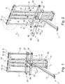
- a base frame 1 comprises, for example, three vertical supports 2-4, a first cross strut 5 and a second cross strut 6, two connecting elements 7, 8, an attachment means 9, 10 and a support leg 11 ( Figures 1 to 3 and 5 to 8) .
- the belt frame 1 is for example for a two-seater vehicle seat (not shown) formed.
- the vertical supports 2-4 are provided in the arranged state on the base frame 1, vertically aligned.
- the vertical supports 2-4 are spaced apart from one another and, for example, are present next to one another parallel to one another.
- attachment means 10 are provided in order to fasten the vertical supports 2-4 in the arranged state to a vehicle (not shown), for example to screw them to a vehicle floor.
- the transverse struts 5, 6 are advantageously provided perpendicular to the vertical supports 2-4 and are preferably connected, in particular non-detachably, to each of the vertical supports 2-4.
- the cross struts 5, 6 are welded to the vertical supports 2-4.
- the cross struts 5, 6 are screwed and / or riveted to the vertical supports 2-4.
- the first cross strut 5 is advantageously mounted with a rear side on a front side 13 of the vertical support 2-4.
- a surface normal of the front side 13 of the vertical supports 2-4 advantageously points in the arranged state of the belt frame 1 on the vehicle in a direction of travel F of the vehicle, in particular in the direction of the front of the vehicle.
- the second cross strut 6 is arranged, for example, on a head region 14 of the belt frame 1 on one of the vertical supports 2-4 or on each of the vertical supports 2-4.
- Sleeve-like attachment elements 15-18 are formed on the second transverse strut 6, which are provided, for example in pairs, to arrange a headrest (not shown).
- the first cross strut 5 is advantageously fastened to the vertical supports 2-4 approximately at the level of a seat surface of a vehicle seat, the vehicle seat including the base frame 1.
- the first cross strut 5 is formed starting from the attachment means 10 in the vertical direction upwards at the level of a first and / or lowermost third of a length of the vertical supports 2-4.
- the connecting elements 7, 8 are for example in the form of a band, for example a steel band.
- the connecting elements 7, 8 connect the first cross strut 5 and the second cross strut 6 to one another.
- the connecting elements 7, 8 are permanently connected to the transverse struts 5, 6, for example welded.
- the connecting elements 7, 8 are provided, for example, aligned parallel to the vertical supports 2-4 and extend, for example, in the vertical direction.
- the connecting elements 7, 8 are provided to keep the cross struts 5, 6 at a defined, e.g. vertical distance from one another, in particular in the event of a crash.
- the connecting elements 7, 8 are intended to define a maximum vertical spacing of the transverse struts 5, 6 from one another, in particular such that the transverse struts 5, 6 from one another do not exceed the maximum vertical spacing in the event of a crash.
- the connecting elements 7, 8 preferably connect ends of the transverse struts 5, 6 to one another.
- fastening screws 19, 20 are formed at the ends of the first cross strut.
- a safety component of a personal restraint system is fastened to the fastening screws 19, 20, e.g. a belt whip 21, 22 with a belt lock ( Figure 3 ) a 3-point belt safety system.
- a device 23 according to the invention is designed as an elongated, in particular angled profile 24.
- the profile 24 has, for example, two folds 25, 26 in the form of bends, so that it is present in a zigzag shape in cross section.
- the folds 25, 26 advantageously extend along a longitudinal axis of the profile 24.
- the profile 24 has, for example, a first and a second flat profile section 27, 28, the two profile sections 27, 28 advantageously parallel to one another available.
- the first and second profile sections 27, 28 extend in the arranged state on the belt frame 1 advantageously each in a vertical direction, for example parallel to the longitudinal axis of a vertical support 2-4 and along the longitudinal axis of the profile 24.
- the profile 24 has a third flat profile section 29, which is advantageously provided at an angle to the first and second profile section 27, 28.
- the profile section 29 is advantageously horizontally aligned.
- the profile 24 is available in one piece, for example, with the three profile sections 27 - 29 merging into one another via the bevels 25, 26 ( Figures 2 , 3 ).
- the profile 24 further comprises spaced apart receiving organs in the form of recesses 30-32.
- the recesses 30-32 are, for example, cut out of the profile 24, e.g., lasered.
- the recesses 30-32 are present in particular on the second and third profile sections 28, 29 so that the profile 24 can be placed or pushed onto the vertical supports 2-4 in the horizontal direction.
- the recesses 30-32 are matched in particular to an outer contour of the vertical supports 2 - 4 of the belt frame 1, so that the recesses 30-32 in the arranged state of the device 23 on the belt frame 1, the vertical supports 2 - 4 at least on the front side 13 and on side surfaces 33, 34 in particular completely, for example directly adjacent.
- the recesses 30-32 with edge surfaces 35-37 are advantageously in particular flush and / or positively against the front side 13 and the side surfaces 33, 34 of the vertical supports 2-4.
- a width of the third profile section 29 is greater than a depth of the vertical supports 2-4.
- the third profile section 29 extends opposite to the direction of travel F over a rear edge 38 of the vertical support 2-4.
- a front side 39 of the second profile section 28 in the arranged state of the device 23 on the belt frame 1 is flush with a rear side 40 of the vertical supports 2-4.
- a rear side 41 of the second profile section 28 is flush with the rear side 40 of the vertical supports 2-4 in the arranged state of the profile 24 on the belt frame 1, the rear side 41 being opposite and spaced from the front side 39 of the second profile section 28.
- a distance between the recesses 30-32 along the longitudinal axis of the profile 24 advantageously corresponds to a horizontal distance between the vertical supports 2-4 of the belt frame 1, so that the device 23 can be attached to the belt frame 1 in a comparatively simple and precise manner.
- the distances between the recesses 30-32 and the vertical supports 2-4 correspond, for example, to a grid dimension.
- the device 23 also includes mounting means in the form of U-shaped retaining brackets 42 - 45 which are arranged protruding from the first profile section 27.
- the retaining brackets 42 - 45 are screwed and / or welded to the profile 24, for example, at connection points 46 - 53.
- a distance of a stop 54-57 of the retaining brackets 42-45 from a front side 58 of the second profile section 27 is adjustable, for example, before the assembly of the device 23 on the belt frame 1, whereby at the stop 54-57 a holding catch 59 of a child seat 60 in the arranged state of the Child seat 60 engages the belt frame 1.
- a change in the distance between the stop 54 - 57 and the front side 58 is advantageously prevented when the device 23 is arranged on the belt frame 1, e.g. because the retaining brackets 42 - 45 are welded to the profile 24 after the distance has been set.
- the profile 24 comprises slot-like recesses 61, 62, in which, when the device 23 is arranged on the belt frame 1, the connecting elements 7, 8 are present, engaging.
- the slot-like recess 61, 62 extends on the profile 24, preferably on the second and third profile sections 28, 29.
- the recess 61, 62 advantageously encloses a connecting element 7, 8, for example, positively at least on side surfaces 63, 64 and on a front side 65 of the connecting element 7, 8.
- a flag-like connecting element 66, 67 is cut out of the second profile section 28 and bent forward in the direction of the second profile section 27, in particular bent in the direction of travel F when the profile 24 is arranged on the belt frame 1.
- the connecting elements 66, 67 are present in the arranged state on the belt frame 1 resting on the outer side surface 64 of the connecting elements 7, 8 and are connected to these at assembly points 80, 81, for example screwed with screws 68, 69.
- the device 23 comprises clamping means in the form of connecting plates 70, 71.
- the connecting plates 70, 71 are arranged adjacent to the rear side 40 of the vertical support 2-4 and screwed to the profile 24 via screws 72-75.
- a front edge surface 36 of the recesses 30 - 32 is drawn against the front side 13 of the vertical support 2 - 4 and the device 23 is thus clamped to the belt frame 1.
- the device 23 is arranged on the belt frame 1 by means of two connecting plates 70, 71.
- the device is connected to the belt frame in a clamping manner via a single connecting plate on a single vertical support 2-4. It is also conceivable that the device is connected to the belt frame in a clamping manner on all vertical supports of a belt frame.
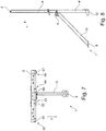
- FIG 4 is an enlarged section of the belt frame 1 according to Figure 2 refer to.
- a portion of the head-side cross brace 6 is shown, on which a bore 76 is formed.
- One end 78 of a top tether band 79 of the child seat 60 can be hooked into the bore 76.
- That Belt frame 1 is provided for a two-seater vehicle seat (not shown), for this reason a further bore 77 is formed on the head-side cross strut for attaching a further child seat.
Description
Vorrichtungen zur Anbringung eines Personenrückhaltesystems in einem Verkehrsmittel sind beispielsweise aus der
In Verkehrsmitteln, wie Fahrzeugen, beispielsweise Personenkraftwagen, Kleinbussen, Wohnmobilen oder Camping-Mobilen werden solche Vorrichtungen zusammen mit verbleibenden Teilen eines Fahrzeugsitz als eine Baueinheit für einen nach der Herstellung des Fahrzeugs nachträglichen Einbau des Fahrzeugsitz im Fahrzeuginneren bereitgestellt. Die Vorrichtung mit dem daran vorhandenen Personenrückhaltesystem muss hierbei für im Fahrzeug auftretende maximale Belastungssituationen ausgelegt sein, die insbesondere im Zusammenhang mit Unfallszenarien im Straßenverkehr auftreten können. Eine nachträgliche Veränderung der Vorrichtung oder einer Funktion der Vorrichtung nach dem Einbau der Vorrichtung im Fahrzeuginneren ist bei den bekannten Vorrichtungen nicht vorgesehen.In means of transport, such as vehicles, for example passenger cars, minibuses, mobile homes or campers, such devices are provided together with remaining parts of a vehicle seat as a structural unit for a subsequent installation of the vehicle seat in the vehicle interior after the vehicle has been manufactured. The device with the personal restraint system present on it must be designed for maximum load situations occurring in the vehicle, which can occur in particular in connection with accident scenarios in road traffic. A subsequent change to the device or a function of the device after the device has been installed in the vehicle interior is not provided for in the known devices.
Bei der Auslegung der Vorrichtung sind insbesondere Sicherheits- bzw. Stabilitätskriterien zu erfüllen, welche zum Beispiel für eine Zulassung der Vorrichtung bzw. des Fahrzeugs erforderlich sind. Die kostengünstige und wirtschaftlich vorteilhafte Ausbildung bzw. Herstellung der Vorrichtung stellt dabei eine besondere Herausforderung dar.When designing the device, safety and stability criteria in particular must be met, which are required, for example, for approval of the device or the vehicle. The cost-effective and economically advantageous design or manufacture of the device represents a particular challenge.
Aufgabe der vorliegenden Erfindung ist es, ein Gurtgestell für einen Fahrzeugsitz mit einer Vorrichtung der einleitend beschriebenen Art bzw. eine Personensitzanordnung für ein Fahrzeug technisch und wirtschaftlich vorteilhaft bereitzustellen. Insbesondere soll das Gurtgestell funktional und vergleichsweise kostengünstig erweiterbar sein.The object of the present invention is to provide a belt frame for a vehicle seat with a device of the type described in the introduction or a passenger seat arrangement for a vehicle in a technically and economically advantageous manner. In particular, the belt frame should be functional and comparatively inexpensive to expand.
Diese Aufgabe wird durch den unabhängigen Anspruch 1 gelöst.This object is achieved by the independent claim 1.
In den abhängigen Ansprüchen werden vorteilhafte und zweckmäßige Weiterbildungen der Erfindung genannt.In the dependent claims, advantageous and expedient developments of the invention are mentioned.
Die Erfindung geht von einem Gurtgestell für einen Fahrzeugsitz oder für eine Fahrzeugsitzbank mit einer Vorrichtung zur Anordnung eines Personenrückhaltesystems in einem Fahrzeug aus, insbesondere geht die Erfindung von einer Vorrichtung zur Anordnung eines Kindersitz aus, um mit dem Personenrückhaltesystem eine in dem Fahrzeug sitzende Person zu sichern aus, wobei die Vorrichtung am Gurtgestell befestigt ist,
wobei das Gurtgestell eine Stützanordnung mit mindestens einer Vertikalstütze und mindestens einer Querstrebe umfasst, und wobei im angeordneten Zustand der Stützanordnung am Fahrzeug die Vertikalstütze aufrecht stehend an einem Fahrzeugboden des Fahrzeugs anordenbar ist.The invention is based on a belt frame for a vehicle seat or for a vehicle bench with a device for arranging a person restraint system in a vehicle, in particular the invention is based on a device for arranging a child seat in order to secure a person sitting in the vehicle with the person restraint system off, with the device attached to the belt frame,
wherein the belt frame comprises a support arrangement with at least one vertical support and at least one cross strut, and wherein, in the arranged state of the support arrangement on the vehicle, the vertical support can be arranged in an upright position on a vehicle floor of the vehicle.
Das Gurtgestell umfasst vorteilhafterweise zwei, insbesondere drei Vertikalstützen, wobei die Vertikalstützen beispielsweise voneinander beabstandete vorhanden sind. Bevorzugterweise verbindet die Querstrebe die mehreren Vertikalstützen miteinander. Die Vertikalstützen sind vorteilhafterweise voneinander lateral bzw. seitlich bzw. horizontal beabstandet vorhanden. Gegebenenfalls kann im Fußbereich der Vertikalstützen eine Verbindung der Vertikalstützen miteinander vorhanden sein, z.B. durch eine Querstrebe, über welche eine Fixierung am Bodenbereich des Fahrzeugs an der Fahrzeugstruktur einrichtbar ist.The belt frame advantageously comprises two, in particular three, vertical supports, the vertical supports, for example, being provided at a distance from one another. The cross strut preferably connects the multiple vertical supports to one another. The vertical supports are advantageously provided laterally or laterally or horizontally spaced from one another. If necessary, a connection of the vertical supports can be made in the foot area of the vertical supports be present with one another, for example by means of a cross strut, via which a fixation on the floor area of the vehicle on the vehicle structure can be set up.
Eine Querstrebe ist vorzugsweise durchgehend ausgebildet und steht bevorzugterweise an der einen oder den mehreren Vertikalstützen horizontal bzw. seitlich über, beispielsweise beidseitig oder einseitig. Demgemäß ist die Querstrebe in der Regel länger als ein Aufstellmaß bzw. ein insbesondere lateraler Abstand von zwei, insbesondere äußeren Vertikalstützen.A cross strut is preferably formed continuously and preferably protrudes horizontally or laterally on the one or more vertical supports, for example on both sides or on one side. Accordingly, the cross strut is generally longer than an installation dimension or, in particular, a lateral distance between two, in particular outer, vertical supports.
Ein solches Gurtgestell ist beispielsweise als Einbauvorrichtung in der Art eines rahmenartigen Gestells ausgebildet, umfassend Freilassungen, die von parallel und winklig zueinander ausgerichteten, miteinander verbundenen, insbesondere länglichen Profilen umrahmt sind. Die Profile bestehen vorzugsweise aus einem metallischen Material.Such a belt frame is designed, for example, as an installation device in the manner of a frame-like frame, comprising openings which are framed by interconnected, in particular elongated, profiles that are aligned parallel and at an angle to one another. The profiles are preferably made of a metallic material.
Beispielsweise umfasst das Gurtgestell auch Anbringmittel zur Anbringung des Gurtgestells an eine Fahrzeugstruktur eines Fahrzeugs im Bereich eines Fahrzeugbodens. Das Gurtgestell ist vorzugsweise derart ausgelegt und ausgebildet, in dem Fahrzeug beziehungsweise in einem Kraftfahrzeug an einem Bodenabschnitt des Fahrzeugs befestigt zu werden. Bevorzugterweise sind die Anbringmittel dazu ausgebildet das Gurtgestell lösbar oder unlösbar fixierbar an der Fahrzeugstruktur, z.B. einem Fahrzeugrahmen, anzubringen. Z.B. ist das Gurtgestell durch die Anbringmittel im angeordneten Zustand am Fahrzeug an die Fahrzeugstruktur angeschraubt und/oder angeschweißt. Die Anbringmittel des Gurtgestells zur Anbringung an eine Fahrzeugstruktur eines Fahrzeugs im Bereich eines Fahrzeugbodens sind beispielsweise am Fußbereich des Gurtgestells ausgebildet.For example, the belt frame also includes attachment means for attaching the belt frame to a vehicle structure of a vehicle in the area of a vehicle floor. The belt frame is preferably designed and constructed in such a way that it is fastened in the vehicle or in a motor vehicle to a floor section of the vehicle. The attachment means are preferably designed to attach the belt frame in a detachable or non-detachable manner to the vehicle structure, for example a vehicle frame. For example, the belt frame is screwed and / or welded to the vehicle structure by the attachment means in the arranged state on the vehicle. The attachment means of the belt frame for attachment to a vehicle structure of a vehicle in the area of a vehicle floor are formed, for example, on the foot area of the belt frame.
Das Fahrzeug ist z.B. als ein Automobil, als ein Autobus, als ein Wohnmobil oder auch als ein Camping-Mobil ausgebildet. Das Gurtgestell bildet vorteilhafterweise eine Grundstruktur für eine Sitzanordnung im Fahrzeug, beziehungsweise für eine Fahrzeugsitzanordnung.The vehicle is for example as an automobile, as a bus, as a mobile home or a camping car. The belt frame advantageously forms a basic structure for a seat arrangement in the vehicle or for a vehicle seat arrangement.
Ein Personen-Rückhaltesystem ist vorteilhafterweise als eine Sicherheitsgurtanordnung, z.B. als ein Mehrpunktgurt-Sicherheitssystem oder als Dreipunktgurt-Sicherheitssystem ausgebildet. Eine derartige Komponente ist z.B. als ein Gurtaufroller, eine Gurtumlenkanordnung zur Richtungsänderung des daran vorbeigeführten Gurts, eine Fixierung eines Gurtendes oder als ein Gurtschloss, an dem ein Einsteckteil lösbar einrastbar ist, mit welchem der Gurt als Schlaufe ausziehbar ist, vorhanden.A personal restraint system is advantageously designed as a safety belt arrangement, e.g. as a multi-point belt safety system or as a three-point belt safety system. Such a component is available, for example, as a belt retractor, a belt deflection arrangement for changing the direction of the belt passed by it, a fixation of a belt end or as a belt lock on which an insert part can be releasably latched, with which the belt can be pulled out as a loop.
Ein weiteres Personen-Rückhaltesystem ist beispielsweise als Kindersitz und/oder als Babysafe vorhanden, der Kindersitz umfasst vorteilhafterweise Halterasten nach der sogenannten "ISOfix"-Norm. Die Halterasten des Kindersitz sind beispielsweise im rückseitigen Bereich des Kindersitz unterhalb einer Sitzfläche des Kindersitz ausgebildet. An der Vorrichtung, welche an das Gurtgestell befestigt ist, ist vorzugsweise eine Komponente des Personen-Rückhaltesystems nach "ISOfix"-Norm anbringbar.Another personal restraint system is available, for example, as a child seat and / or as a baby safe, the child seat advantageously comprises holding latches according to the so-called "ISOfix" standard. The holding latches of the child seat are formed, for example, in the rear area of the child seat below a seat surface of the child seat. A component of the personal restraint system according to the "ISOfix" standard can preferably be attached to the device which is attached to the belt frame.
Das Gurtgestell, an welchem die Vorrichtung anbringbar ist, muss konstruktiv bzw. mechanisch so ausgelegt sein, einer maximal tolerierbaren bzw. möglichen Belastung, insbesondere bei dynamischen Belastungsvorgängen, einen ausreichenden Widerstand entgegensetzen zu können, also entsprechende Kräfte und Momente aufzunehmen und weitergeben zu können. Dies ist Voraussetzung zur Erhaltung der Sicherheit einer Person, welche mittels eines Personenrückhaltesystems über die Vorrichtung am Gurtgestell gesichert ist. Das Gurtgestell ist demgemäß vorzugsweise dazu ausgestaltet, eine innere Gerüststruktur eines fest im Fahrzeug installierten Personensitzes zu bilden.The belt frame to which the device can be attached must be structurally or mechanically designed to be able to oppose a maximum tolerable or possible load, especially in dynamic loading processes, with sufficient resistance, i.e. to be able to absorb and pass on corresponding forces and torques. This is a prerequisite for maintaining the safety of a person who is secured by means of a person restraint system via the device on the belt frame. The belt frame is accordingly preferably designed to have an inner framework structure of a fixedly installed in the vehicle To form a passenger seat.
Für eine vergleichsweise höhere Stabilität des Gurtgestells, z.B. für eine erweiterte Einsatzmöglichkeit auf einen Personensitz mit zwei oder mehr Sitzplätzen, kann das Gurtgestell zum Beispiel genau zwei oder genau drei parallele, z.B. voneinander beabstandete Vertikalstützen umfassen, wobei die Vertikalstützen vorzugsweise identisch aufgebaut sind. Beide Vertikalstützen sind bevorzugt mit einer horizontal angeordneten Querstrebe verbunden.For a comparatively higher stability of the belt frame, e.g. for an extended application possibility to a passenger seat with two or more seats, the belt frame can for example comprise exactly two or exactly three parallel, e.g. spaced apart vertical supports, whereby the vertical supports are preferably constructed identically. Both vertical supports are preferably connected with a horizontally arranged cross strut.
Bei einem typischen vorteilhaften Gurtgestell mit zwei oder drei senkrecht im Fahrzeug aufstellbaren Vertikalstützen und einer horizontal gerichteten Querstrebe beträgt die Länge der Vertikalstützen bzw. die Höhe des Gurtgestells im montierten Zustand etwa 1,1 m bis ca. 1,3 m, wobei die Vertikalstützen, insbesondere die beiden äußeren Vertikalstützen, über einen Abstand von z.B. ca. 0,3 m bis 0,4 m voneinander seitlich beabstandet vorhanden sind. Eine Länge der Querstrebe liegt bevorzugterweise bei ca. 0,7 m bis 0,9 m.In a typical advantageous belt frame with two or three vertical supports that can be set up vertically in the vehicle and a horizontally directed cross strut, the length of the vertical supports or the height of the belt frame in the assembled state is approximately 1.1 m to approximately 1.3 m, with the vertical supports, in particular the two outer vertical supports are present at a distance of, for example, about 0.3 m to 0.4 m laterally spaced from one another. A length of the cross strut is preferably about 0.7 m to 0.9 m.
Die Vertikalstütze und/oder die Querstrebe ist vorteilhafterweise als ein Hohlprofil ausgebildet. Im Querschnitt ist das Hohlprofil typischerweise rechteckig oder quadratisch vorhanden, denkbar ist aber auch, dass das Hohlprofil im Querschnitt rund oder elliptisch ausgebildet ist. Ein typisches Längen- und/oder Breitenmaß bzw. Seitenmaß des Querschnitts des Hohlprofils beträgt ca. 20 mm bis 40 mm. Eine Wanddicke des Hohlprofils liegt in der Regel in einem einstelligen Millimeterbereich. Denkbar ist auch, dass das Hohlprofil als ein Mehrfachhohlprofil vorhanden ist.The vertical support and / or the cross strut is advantageously designed as a hollow profile. The hollow profile is typically rectangular or square in cross section, but it is also conceivable that the hollow profile is round or elliptical in cross section. A typical length and / or width dimension or side dimension of the cross section of the hollow profile is approximately 20 mm to 40 mm. A wall thickness of the hollow profile is usually in a single-digit millimeter range. It is also conceivable that the hollow profile is present as a multiple hollow profile.
Des Weiteren ist es vorstellbar, dass das Hohlprofil, insbesondere die Vertikalstütze, eine Materialausnehmung z.B. eine Schlitzung aufweist, welche als Soll-Biegestelle im Belastungsfall des angeordneten Gurtgestells, z.B. in einem Crashfall des Fahrzeugs ausgebildet ist. Damit ist ein plastisches Verformungsverhalten der Vertikalstütze in einem Belastungsfall beeinflussbar, insbesondere vorgebbar. Vorteilhafterweise erstreckt sich die Ausnehmung an der Vertikalstütze insbesondere in horizontaler Richtung über eine Vorderseite der Vertikalstütze und über zumindest einen an die Vorderseite anschließenden seitlichen Bereich der Vertikalstütze. Insbesondere erstreckt sich die Materialausnehmung abschnittsweise auf der Vorderseite und auf zwei seitlich an die Vorderseite anschließende sich gegenüberliegende seitliche Bereiche der Vertikalstütze. Die Vorderseite ist bezogen auf einen Anbringzustand des Gurtgestells im Fahrzeug zu verstehen.Furthermore, it is conceivable that the hollow profile, in particular the vertical support, has a material recess, for example a slot, which is used as a desired bending point when the belt frame is loaded, for example in a Crash case of the vehicle is formed. In this way, a plastic deformation behavior of the vertical support can be influenced, in particular predefined, in the event of a load. Advantageously, the recess on the vertical support extends in particular in the horizontal direction over a front side of the vertical support and over at least one lateral area of the vertical support adjoining the front side. In particular, the material recess extends in sections on the front side and on two opposite side areas of the vertical support that adjoin the front side. The front side is to be understood in relation to an attachment state of the belt frame in the vehicle.
Ein mit dem Gurtgestell bildbarer Fahrzeug- bzw. Personensitz weist demgemäß eine Sitzstruktur mit einer Sitzfläche auf, welche sich an der Vorderseite des Personensitzes und damit an der Vorderseite des Gurtgestells bzw. der Vorderseite der Vertikalstütze und/oder einer Vorderseite der Querstrebe befindet, wobei die Vorderseite der Vertikalstütze und die Vorderseite der Querstrebe vorteilhafterweise in Fahrtrichtung ausgerichtet ist.A vehicle or person seat that can be formed with the belt frame accordingly has a seat structure with a seat surface which is located on the front side of the passenger seat and thus on the front side of the belt frame or the front side of the vertical support and / or a front side of the cross strut The front of the vertical support and the front of the cross strut is advantageously aligned in the direction of travel.
Im eingebauten Zustand des Gurtgestells im Fahrzeug entspricht die relevante Belastungsrichtung in der Regel einer Sitzrichtung der gesicherten Person bzw. der Fahrtrichtung des Fahrzeugs. Bei einem Fahrzeug tritt eine maximale Belastung z.B. bei einem Aufprall des fahrenden Fahrzeugs gegen ein Hindernis auf, einem Crashfall. Aufgrund der abgebremsten Masse der im Fahrzeug sitzenden und gesicherten Person wird über die Sicherheitsgurte des Personenrückhaltesystems eine ruckartig wirkende Zugkraft bzw. ein daraus resultierendes Moment in der Belastungsrichtung bzw. in Fahrtrichtung an der am Gurtgestell befestigten Vorrichtung und damit am Gurtgestell wirksam.When the belt frame is installed in the vehicle, the relevant loading direction generally corresponds to the seated direction of the secured person or the direction of travel of the vehicle. In the case of a vehicle, a maximum load occurs, for example, when the moving vehicle collides with an obstacle, in the event of a crash. Due to the braked mass of the person seated and secured in the vehicle, a jerky tensile force or a torque resulting therefrom in the loading direction or in the direction of travel is effective on the device attached to the belt frame and thus on the belt frame via the seat belts of the personal restraint system.
Ein wesentlicher Aspekt der Erfindung ist nun darin zu sehen, dass die Vorrichtung als längliches Profil vorhanden ist, wobei die Vorrichtung entlang einer Längsachse des Profils Montagemittel zur Befestigung von Halterasten des Personenrückhaltesystems, insbesondere eines ISOfix-Personenrückhaltesystems, aufweist, wobei die Montagemittel entlang der Längsachse des Profils voneinander beabstandet vorhanden sind und wobei die Vorrichtung in Form eines länglichen Profils als vom Gurtgestell separate Anbaueinheit vorhanden ist und nachträglich am Gurtgestell anbringbar ist. Hierdurch ist das Gurtgestell und/oder die Vorrichtung vergleichsweise kostengünstig herstellbar. Beispielsweise ist eine Ausbildungsvariante der Vorrichtung des erfindungsgemäßen Gurtgestells an unterschiedlichen Gurtgestellvarianten befestigbar. Hierdurch sind Entwicklungskosten und Herstellungskosten aufgrund einer höheren Stückzahl der Vorrichtungen vergleichsweise verringert.An essential aspect of the invention can now be seen in the fact that the device is present as an elongated profile, the device having mounting means along a longitudinal axis of the profile for attaching retaining latches of the personal restraint system, in particular an ISOfix personal restraint system, the mounting means along the longitudinal axis of the profile are present at a distance from one another and wherein the device is present in the form of an elongated profile as an attachment unit separate from the belt frame and can be subsequently attached to the belt frame. As a result, the belt frame and / or the device can be manufactured comparatively inexpensively. For example, a design variant of the device of the belt frame according to the invention can be attached to different belt frame variants. As a result, development costs and manufacturing costs are comparatively reduced due to a higher number of devices.
Vorteilhafterweise ist die Vorrichtung lösbar fixierbar an das Gurtgestell anordenbar. Die Vorrichtung und das Gurtgestell ist bevorzugterweise derart ausgebildet, dass die Vorrichtung an das Gurtgestell nachrüstbar vorhanden ist, insbesondere im angeordneten Zustand des Gurtgestells am Fahrzeugsitz.Advantageously, the device can be releasably fixable on the belt frame. The device and the belt frame are preferably designed in such a way that the device can be retrofitted to the belt frame, in particular when the belt frame is arranged on the vehicle seat.
Beispielsweise erfüllt die Vorrichtung, insbesondere im angeordneten Zustand am Gurtgestell bzw. am Fahrzeugsitz, die sogenannte "ISOfix"-Norm ISO 13216.For example, the device fulfills the so-called “ISOfix” standard ISO 13216, in particular when it is arranged on the belt frame or on the vehicle seat.
Überdies ist es von Vorteil, dass das Profil als abgekantetes Profil, insbesondere abgekantetes Profilband, vorhanden ist. Hierdurch ist die Vorrichtung zum einen vergleichsweise günstig herstellbar und zum anderen vergleichsweise stabil vorhanden.In addition, it is advantageous that the profile is present as a beveled profile, in particular a beveled profile strip. As a result, the device can on the one hand be produced comparatively inexpensively and on the other hand is present in a comparatively stable manner.
Das Profil ist vorteilhafterweise als ein insbesondere abgekantetes Stahlband vorhanden, z.B. als abgekantete Profilleiste und/oder abgekantete Stahlleiste. Das Profil ist in einem Querschnitt beispielsweise L-förmig oder U-förmig vorhanden, hierdurch ist es gegenüber einer Querkraft, welche insbesondere senkrecht zu einer Längsachse des Profils am Profil angreift, insbesondere im Crashfall, vergleichsweise stabil vorhanden. Das Profil ist vorteilhafterweise einstückig ausgebildet. Hierdurch ist die Vorrichtung vergleichsweise kostengünstig herstellbar.The profile is advantageously in the form of a particularly beveled steel strip, for example as a beveled profile strip and / or beveled steel strip. The profile is present in a cross-section, for example L-shaped or U-shaped, as a result of which it is comparatively stable with respect to a transverse force which acts on the profile in particular perpendicular to a longitudinal axis of the profile, in particular in the event of a crash. The profile is advantageously formed in one piece. As a result, the device can be manufactured comparatively inexpensively.
Erfindungsgemäß ist das Profil derart vorhanden, dass das Profil im angeordneten Zustand am Gurtgestell die Vertikalstütze umgreift. Beispielsweise umschließt das Profil im angeordneten Zustand am Gurtgestell die Vertikalstütze, insbesondere vollständig, z.B. klammerartig. Dadurch ist das Profil vergleichsweise einfach an das Gurtgestell anordenbar, insbesondere vergleichsweise einfach am Gurtgestell fixierbar.According to the invention, the profile is present in such a way that the profile engages around the vertical support in the arranged state on the belt frame. For example, in the arranged state on the belt frame, the profile encloses the vertical support, in particular completely, e.g. in a clamp-like manner. As a result, the profile can be arranged comparatively easily on the belt frame, in particular it can be fixed comparatively easily on the belt frame.
Bevorzugterweise umfasst das Profil ein Aufnahmeorgan zur Aufnahme der Vertikalstütze des Gurtgestells im angeordneten Zustand. Das Aufnahmeorgan ist vorteilhafterweise als Aussparung ausgebildet. Das Aufnahmeorgan umschließt die Vertikalstütze im angeordneten Zustand am Gurtgestell z.B. an drei Seiten, z.B. durch Seitenränder der Aussparung.The profile preferably comprises a receiving member for receiving the vertical support of the belt frame in the arranged state. The receiving member is advantageously designed as a recess. The receiving element encloses the vertical support in the arranged state on the belt frame, e.g. on three sides, e.g. by side edges of the recess.
Außerdem erweist es sich von Vorteil, dass die Vorrichtung Klemmmittel aufweist, wobei die Vorrichtung im angeordneten Zustand am Gurtgestell durch die Klemmmittel an der Vertikalstütze des Gurtgestells fixiert ist, z.B. geklemmt. Denkbar ist weiterhin, dass die Klemmmittel in einer Weise ausgebildet sind, dass die Vorrichtung werkzeuglos am Gurtgestell fixierbar ist. Vorstellbar ist weiterhin, dass die Vorrichtung und/oder die Klemmmittel im angeordneten Zustand am Gurtgestell lösbar, z.B. auswechselbar, am Gurtgestell vorhanden sind.It also proves to be advantageous that the device has clamping means, the device being fixed, e.g. clamped, to the vertical support of the belt frame in the arranged state on the belt frame by the clamping means. It is also conceivable that the clamping means are designed in such a way that the device can be fixed to the belt frame without tools. It is also conceivable that the device and / or the clamping means in the arranged state on the belt frame are detachable, e.g. exchangeable, on the belt frame.
Vorteilhafterweise erstreckt sich im angeordneten Zustand am Gurtgestell das längliche Profil, insbesondere eine Außenkante der Aussparung des Profils, bis an einen rückwärtigen Bereich der Vertikalstütze. Z.B. erstreckt sich das Profil derart, dass es im angeordneten Bereich am Gurtgestell bündig mit einer Hinterkante und/oder einer Rückseite der Vertikalstütze vorhanden ist. Denkbar ist auch, dass das Profil im angeordneten Zustand über den rückwärtigen Bereich der Vertikalstütze überstehend vorhanden ist. Das längliche Profil umfasst beispielsweise Montageöffnungen, z.B. Bohrungen, zur Aufnahme der Klemmmittel. Denkbar ist weiterhin, dass im angeordneten Zustand am Gurtgestell, das Profil, insbesondere die Aussparung des Profils, und das Klemmmittel anliegend an der Vertikalstütze vorhanden sind, z.B. in Kontakt mit der Vertikalstütze vorhanden sind. Im angeordneten Zustand am Gurtgestell sind die Klemmmittel insbesondere ausschließlich an der Rückseite der Vertikalstütze an der Vertikalstütze anliegend vorhanden. Eine Länge des Klemmmittels ist vorteilhafterweise gleich oder größer als eine Breite der Vertikalstütze. Die Rückseite der Vertikalstütze erstreckt sich beispielsweise entlang der Breite und einer Länge der Vertikalstütze.The elongated profile, in particular an outer edge, advantageously extends in the arranged state on the belt frame the recess of the profile, up to a rear area of the vertical support. For example, the profile extends in such a way that it is flush with a rear edge and / or a rear side of the vertical support in the area arranged on the belt frame. It is also conceivable that the profile in the arranged state protrudes beyond the rear area of the vertical support. The elongated profile includes, for example, assembly openings, for example bores, for receiving the clamping means. It is also conceivable that in the arranged state on the belt frame, the profile, in particular the recess of the profile, and the clamping means are present adjacent to the vertical support, for example in contact with the vertical support. In the arranged state on the belt frame, the clamping means are in particular only present in contact with the vertical support on the rear side of the vertical support. A length of the clamping means is advantageously equal to or greater than a width of the vertical support. The back of the vertical support extends, for example, along the width and a length of the vertical support.
Vorstellbar ist, dass sich die Breite des Klemmmittels im angeordneten Zustand am Gurtgestell bis an die Hinterkante der Rückseite der Vertikalstütze erstreckt. Vorteilhafterweise erstreckt sich das Klemmmittel entlang seiner Breite im angeordneten Zustand am Gurtgestell über eine Hinterkante der Rückseite der Vertikalstütze hinaus, insbesondere über die Breite der Vertikalstütze hinaus. Im angeordneten Zustand des Klemmmittels und des Profils am Gurtgestell erstrecken sich das Klemmmittel und das Profil vorteilhafterweise parallel zueinander, insbesondere erstreckt sich die Längsachse des Profils parallel zu einer Vorderseite des Klemmmittels, wobei das Klemmmittel mit der Vorderseite bspw. anliegend an einer Vertikalstütze des Gurtgestells vorhanden ist. Beispielsweise erstrecken sich die Breite des Klemmmittels und die Längsachse des Profils im angeordneten Zustand am Gurtgestell in einer horizontalen Richtung.It is conceivable that the width of the clamping means in the arranged state on the belt frame extends to the rear edge of the rear of the vertical support. Advantageously, the clamping means extends along its width in the arranged state on the belt frame beyond a rear edge of the rear side of the vertical support, in particular beyond the width of the vertical support. In the arranged state of the clamping means and the profile on the belt frame, the clamping means and the profile extend advantageously parallel to one another, in particular the longitudinal axis of the profile extends parallel to a front side of the clamping means, the clamping means with the front side, for example, lying against a vertical support of the belt frame is. For example, the width of the clamping means and the longitudinal axis of the profile in the arranged state on the belt frame extend in one horizontal direction.
In einer vorteilhaften Ausgestaltung der Vorrichtung ist ein Abstand einer Haltestelle des Montagemittels von einem Anbindungspunkt des Montagemittels am Profil einstellbar vorhanden, wobei im angeordneten Zustand eine Halteraste des Personenrückhaltesystems an der Haltestelle des Montagemittels angreift. Hierdurch ist das Gurtgestell, insbesondere die Vorrichtung, an eine Ausgestaltung eines Fahrzeugsitzes anpassbar. Beispielsweise an eine Polsterdicke des Fahrzeugsitzes. Durch die Anpassbarkeit der Vorrichtung ist eine Montage des Personenrückhaltesystems an den Montagemitteln vereinfacht.In an advantageous embodiment of the device, a distance between a stop of the assembly means and a connection point of the assembly means on the profile is adjustable, with a holding latch of the personal restraint system engaging the stop of the assembly means in the arranged state. As a result, the belt frame, in particular the device, can be adapted to a configuration of a vehicle seat. For example, a cushion thickness of the vehicle seat. The adaptability of the device simplifies the assembly of the personal restraint system on the assembly means.
Vorteilhafterweise sind zwei Montagemittel zur Befestigung eines Personenrückhaltesystems an der Vorrichtung vorgesehen. Ein Montagemittel ist vorteilhafterweise als ein Bügel, z.B. als ein Haltebügel ausgebildet. Denkbar ist, dass ein Montagemittel U-förmig oder L-förmig vorhanden ist. Das Montagemittel ist z.B. formstabil vorhanden. Das Montagemittel ist dazu vorgesehen mit einer Halteraste des Personenrückhaltesystems, insbesondere mit einer Halteraste eines Kindersitz, zu verrasten, z.B. eine lösbare Verbindung einzugehen.Advantageously, two mounting means are provided for attaching a personal restraint system to the device. A mounting means is advantageously designed as a bracket, for example as a retaining bracket. It is conceivable that a U-shaped or L-shaped assembly means is present. The assembly means is e.g. dimensionally stable. The mounting means is intended to be locked with a retaining clip of the personal restraint system, in particular with a retaining clip of a child seat, e.g. to establish a detachable connection.
Beispielsweise ist ein Abstand der Haltestelle von dem Anbindungspunkt des Montagemittels am Profil über Schraubmittel einstellbar ausgebildet. Beispielsweise ist das Montagemittel als U-förmiger Haltebügel vorhanden, wobei offene Enden des U-förmigen Haltebügels Außengewinde aufweisen, z.B. gewindestangenartig vorhanden sind. Hierdurch ist ein Abstand der Haltestelle von dem Anbindungspunkt des Montagemittels am Profil vergleichsweise einfach über Schraubmittel justierbar. Beispielsweise sind die Montagemittel im angeordneten Zustand am Profil mit dem Profil über eine Schraubverbindung lösbar, insbesondere justierbar, verbunden. Denkbar ist auch, dass die Montagemittel an das Profil geschweißt, genietet und/oder geklebt sind. Vorteilhafterweise sind die Montagemittel abstehend vom Profil am Profil vorhanden.For example, a distance between the stop and the connection point of the assembly means on the profile is adjustable via screw means. For example, the mounting means is present as a U-shaped retaining bracket, with open ends of the U-shaped retaining bracket having external threads, for example being present in the manner of a threaded rod. As a result, a distance between the stop and the connection point of the assembly means on the profile can be adjusted comparatively easily by means of screw means. For example, in the arranged state on the profile with the profile, the assembly means can be detached, in particular adjusted, via a screw connection, tied together. It is also conceivable that the assembly means are welded, riveted and / or glued to the profile. The mounting means are advantageously present on the profile protruding from the profile.
Weiter wird vorgeschlagen, dass die Vorrichtung, insbesondere das Profil, ein Rastermaß aufweist. Durch das Rastermaß ist das Profil derart vorhanden, dass es an unterschiedliche Gurtgestelle, welche ebenfalls das Rastermaß aufweisen anordenbar ist. Insbesondere ist eine einzige Vorrichtung für unterschiedliche Gurtgestelle verwendbar. Hierdurch sind die Gurtgestelle vergleichsweise kostengünstig und einfach mit einem Personenrückhaltesystem, insbesondere mit einem Isofix-Personenrückhaltesystem zur Befestigung eines Kindersitz und/oder eines Babysafes, nachrüstbar.It is further proposed that the device, in particular the profile, have a grid dimension. Due to the grid dimension, the profile is present in such a way that it can be arranged on different belt frames, which also have the grid dimension. In particular, a single device can be used for different belt racks. As a result, the belt frames can be retrofitted comparatively inexpensively and easily with a person restraint system, in particular with an Isofix person restraint system for attaching a child seat and / or a baby safe.
Vorteilhafterweise ist das Gurtgestell in einer Weise ausgebildet, dass eine am Gurtgestell befestigte Vorrichtung am Gurtgestell fixiert ist.The belt frame is advantageously designed in such a way that a device attached to the belt frame is fixed to the belt frame.
Als vorteilhaft erweist sich auch, dass die Stützanordnung des Gurtgestells zwei Querstreben aufweist, wobei eine erste Querstrebe an einem oberen Ende der Stützanordnung vorhanden ist, wobei die erste Querstrebe zur Anordnung einer Kopfstütze des Fahrzeugsitzes ausgebildet ist, wobei eine zweite Querstrebe in vertikaler Richtung betrachtet in einem mittleren Bereich der Stützanordnung vorhanden ist, wobei im angeordneten Zustand des Gurtgestells am Fahrzeugsitz an der zweiten Querstrebe Komponenten eines Personenrückhaltesystems angeordnet sind, wobei die erste und die zweite Querstrebe sich in horizontaler Richtung an der Stützanordnung erstrecken, wobei an einem äußeren Bereich der ersten und der zweiten Querstrebe die erste und die zweite Querstrebe in vertikaler Erstreckung betrachtet durch ein bandartiges Element miteinander verbunden sind, wobei das bandartige Element Anbindungsmittel aufweist, wodurch eine der oben genannten Varianten der Vorrichtung im angeordneten Zustand am Gurtgestell fixiert ist. Hierdurch sind das Profil und das Gurtgestell vergleichsweise stabiler vorhanden, wobei eine Energieabsorption und Weiterleitung, insbesondere im Crashfall, von auf das Profil und/oder das Gurtgestell wirkenden Kräften verbessert ist.It also proves to be advantageous that the support arrangement of the belt frame has two cross struts, a first cross strut being present at an upper end of the support arrangement, the first cross strut being designed for the arrangement of a headrest of the vehicle seat, with a second cross strut viewed in the vertical direction in a central region of the support arrangement is present, wherein in the arranged state of the belt frame on the vehicle seat on the second cross strut components of a person restraint system are arranged, the first and the second cross strut extending in the horizontal direction on the support arrangement, with the first and of the second transverse strut, the first and the second transverse strut, viewed in vertical extension, are connected to one another by a band-like element, the band-like element having connecting means, whereby one of the above mentioned variants of the device is fixed in the arranged state on the belt frame. As a result, the profile and the belt frame are comparatively more stable, with energy absorption and transmission, in particular in the event of a crash, of forces acting on the profile and / or the belt frame being improved.
Das bandartige Element ist beispielsweise als Flachstahl oder als Blechstreifen vorhanden. Denkbar ist auch, dass das bandartige Element als ein Band, insbesondere als ein Gurtband ausgebildet ist. Das bandartige Element ist vorteilhafterweise unlösbar mit den Querstreben verbunden. Das bandartige Element ist z.B. mit den Querstreben verschraubt, vernietet, verschweißt, verlötet und/oder verklebt. Bevorzugterweise sind zwei bandartige Elemente an der Stützanordnung vorgesehen, wobei die beiden bandartigen Elemente voneinander beabstandet an gegenüberliegenden Enden der Querstreben befestigt sind.The band-like element is available, for example, as flat steel or as sheet metal strips. It is also conceivable that the band-like element is designed as a band, in particular as a belt strap. The band-like element is advantageously permanently connected to the cross struts. The ribbon-like element is, for example, screwed, riveted, welded, soldered and / or glued to the cross struts. Preferably, two band-like elements are provided on the support arrangement, the two band-like elements being attached to opposite ends of the transverse struts at a distance from one another.
Vorteilhafterweise ist ein Anbindungsmittel als Öffnung, Loch und/oder Bohrung, z.B. Durchgangsbohrung, am bandartigen Element ausgebildet, wobei die Vorrichtung durch Befestigungsmittel, z.B. in Form einer Schraube und/oder einer Niete, an der Öffnung des bandartigen Elements insbesondere lösbar befestigbar ist. Beispielsweise ist die Vorrichtung im angeordneten Zustand am Gurtgestell an voneinander beabstandeten Enden des Profils jeweils mit einem Ende des Profils mit einem bandartigen Element des Gurtgestells verbindbar vorhanden.A connecting means is advantageously designed as an opening, hole and / or bore, e.g. through hole, on the band-like element, the device being particularly releasably attachable to the opening of the band-like element by fastening means, e.g. in the form of a screw and / or a rivet. For example, the device is present in the arranged state on the belt frame at ends of the profile that are spaced apart from one another and can be connected to one end of the profile with a band-like element of the belt frame.
Beispielsweise sind am Gurtgestell, insbesondere am Fahrzeugsitz, zwei insbesondere zueinander verschiedene Personenrückhaltesysteme vorhanden. Z.B. ein Dreipunktgurt-Sicherheitssystem und/oder ein Mehrfachpunktgurt-Sicherheitssystem und ein Personenrückhaltesystem für einen Kindersitz, z.B. entsprechend der "ISOfix-Norm".For example, two personal restraint systems, in particular different from one another, are provided on the belt frame, in particular on the vehicle seat. For example, a three-point belt safety system and / or a multi-point belt safety system and a personal restraint system for a child seat, for example in accordance with the "ISOfix standard".
Überdies ist es von Vorteil, dass die Vorrichtung in einer vertikalen Erstreckung der Stützanordnung betrachtet in einem Bereich zwischen der ersten und der zweiten Querstrebe am Gurtgestell angeordnet, insbesondere vorhanden ist. An der ersten und an der zweiten Querstrebe sind im angeordneten Zustand des Gurtgestells am Fahrzeugsitz und/oder am Fahrzeug vorteilhafterweise Komponenten eines Personen-Sicherheitssystems befestigt, insbesondere eines Dreipunktgurt-Sicherheitssystems. Z.B. ist an der zweiten Querstrebe ein Gurtschloss befestigbar und an der ersten Querstrebe z.B. ein Gurtaufroller.In addition, it is advantageous that the device, viewed in a vertical extent of the support arrangement, is arranged, in particular present, in an area between the first and the second cross strut on the belt frame. In the arranged state of the belt frame on the vehicle seat and / or on the vehicle, components of a personal safety system, in particular a three-point belt safety system, are advantageously attached to the first and to the second cross strut. For example, a belt lock can be attached to the second cross strut and a belt retractor, for example, to the first cross strut.
Außerdem wird vorgeschlagen, dass an der ersten Querstrebe Montagemittel zur Befestigung eines Top-Tether-Bands eines Personenrückhaltesystems, insbesondere eines Kindersitz, vorhanden sind. Vorteilhafterweise sind die Montagemittel an der ersten Querstrebe in einem Bereich zwischen Montagepunkten einer Kopfstütze des Fahrzeugsitzes vorhanden. Ein Montagemittel ist beispielsweise als Aussparung und/oder Öffnung, z.B. als eine Bohrung an der ersten Querstrebe vorhanden. Hierdurch ist das Top-Tether-Band vergleichsweise einfach an der ersten Querstrebe befestigbar, z.B. einhängbar.It is also proposed that mounting means for fastening a top tether band of a person restraint system, in particular a child seat, are present on the first cross strut. The mounting means are advantageously present on the first cross strut in an area between mounting points of a headrest of the vehicle seat. A mounting means is present, for example, as a recess and / or opening, e.g. as a hole in the first cross strut. This makes it comparatively easy to attach the top tether tape to the first cross brace, e.g. hang it on.
Auch erweist es sich von Vorteil, dass das Gurtgestell ein Rastermaß aufweist. Das Rastermaß des Gurtgestells ist insbesondere derart ausgebildet, dass ein horizontaler Abstand der Vertikalstrebe oder ggf. der Vertikalstreben und der bandartigen Elemente das Rastermaß vorgeben. Vorteilhafterweise ist bei zueinander unterschiedlichen Gurtgestellen der horizontale Abstand der Vertikalstrebe oder der Vertikalstreben und/oder der bandartigen Elemente gleich. Hierdurch ist eine einzige Vorrichtung an mehrere zueinander unterschiedliche Gurtgestelle anordenbar.It also proves to be advantageous that the belt frame has a grid dimension. The grid dimension of the belt frame is designed, in particular, in such a way that a horizontal distance between the vertical strut or, if applicable, the vertical struts and the band-like elements define the grid dimension. The horizontal spacing of the vertical strut or the vertical struts and / or the band-like elements is advantageously the same in the case of different belt racks. As a result, a single device can be arranged on several different belt frames.
Ein Ausführungsbeispiel wird anhand der nachstehenden schematischen Zeichnungen unter Angabe weiterer Einzelheiten und Vorteile näher erläutert.An exemplary embodiment is explained in more detail with reference to the following schematic drawings, specifying further details and advantages.
Es zeigen:
- Figur 1
- in einer perspektivischen Ansicht von schräg seitlich vorne oben ein Gurtgestell mit einer erfindungsgemäßen Vorrichtung im angeordneten Zustand am Gurtgestell,
Figur 2- in einer perspektivischen Ansicht von schräg seitlich vorne oben das Gurtgestell aus
Figur 1 mit der Vorrichtung in einer Explosionsdarstellung, Figur 3- in einer perspektivischen Ansicht von schräg seitlich vorne oben das Gurtgestell aus
Figur 1 mit angeordneten Gurtpeitschen und einem Personenrückhaltesystem in einem vom Gurtgestell losgelösten Zustand, Figur 4- eine Detailansicht des Gurtgestells aus
Figur 1 , Figur 5- eine Frontansicht des Gurtgestells aus
Figur 1 , Figur 6- eine Rückansicht des Gurtgestells aus
Figur 1 , Figur 7- eine Aufsicht auf das Gurtgestell aus
Figur 1 und Figur 8- eine Seitenansicht auf das Gurtgestell aus
Figur 1 .
- Figure 1
- in a perspective view from obliquely laterally at the front and top a belt frame with a device according to the invention in the arranged state on the belt frame,
- Figure 2
- in a perspective view from obliquely from the side in front above the belt frame
Figure 1 with the device in an exploded view, - Figure 3
- in a perspective view from obliquely from the side in front above the belt frame
Figure 1 with arranged belt whips and a person restraint system in a state detached from the belt frame, - Figure 4
- a detailed view of the belt frame
Figure 1 , - Figure 5
- a front view of the belt frame
Figure 1 , - Figure 6
- a rear view of the belt frame
Figure 1 , - Figure 7
- a plan view of the belt frame
Figure 1 and - Figure 8
- a side view of the belt frame
Figure 1 .
Ein Grundgestell 1 umfasst z.B. unter anderem drei Vertikalstützen 2 - 4, eine erste Querstrebe 5 und eine zweite Querstrebe 6, zwei Verbindungselemente 7, 8, ein Anbringmittel 9, 10 und einen Stützfuß 11 (
Längsachsen der drei Vertikalstützen 2 - 4 sind im angeordneten Zustand am Grundgestell 1 vertikal ausgerichtet vorhanden. Die Vertikalstützen 2 - 4 sind beabstandet voneinander und beispielsweise parallel zueinander nebeneinander vorhanden. Im Fußbereich 12 der Vertikalstützen 2 - 4 sind Anbringmittel 10 vorgesehen, um die Vertikalstützen 2 - 4 im angeordneten Zustand an einem Fahrzeug (nicht dargestellt) zu befestigen, zum Beispiel an einem Fahrzeugboden anzuschrauben. Vorteilhaft senkrecht zu den Vertikalstützen 2 - 4 sind die Querstreben 5, 6 vorhanden und bevorzugterweise mit jeder der Vertikalstützen 2 - 4 insbesondere unlösbar verbunden. Beispielsweise sind die Querstreben 5, 6 an die Vertikalstützen 2 - 4 angeschweißt. Denkbar ist auch, dass die Querstreben 5, 6 mit den Vertikalstützen 2 - 4 verschraubt und/oder vernietet sind. Vorteilhafterweise ist die erste Querstrebe 5 mit einer Rückseite an einer Vorderseite 13 der Vertikalstütze 2 - 4 montiert. Eine Oberflächennormale der Vorderseite 13 der Vertikalstützen 2 - 4 zeigt vorteilhafterweise im angeordneten Zustand des Gurtgestells 1 am Fahrzeug in eine Fahrtrichtung F des Fahrzeugs, insbesondere in Richtung Fahrzeugfront.Longitudinal axes of the three vertical supports 2-4 are provided in the arranged state on the base frame 1, vertically aligned. The vertical supports 2-4 are spaced apart from one another and, for example, are present next to one another parallel to one another. In the
Die zweite Querstrebe 6 ist beispielsweise an einem Kopfbereich 14 des Gurtgestells 1 an einer der Vertikalstützen 2 - 4 oder an jeder der Vertikalstützen 2 - 4 angeordnet. An der zweiten Querstrebe 6 sind hülsenartige Anbringelemente 15 - 18 ausgebildet, welche dazu vorgesehen sind, z.B. jeweils paarweise, eine Kopfstütze (nicht dargestellt) anzuordnen.The
Die erste Querstrebe 5 ist vorteilhafterweise etwa auf Höhe einer Sitzfläche eines Fahrzeugsitz an den Vertikalstützen 2 - 4 befestigt, wobei der Fahrzeugsitz das Grundgestell 1 umfasst. Insbesondere ist die erste Querstrebe 5 ausgehend von den Anbringmittel 10 in vertikaler Richtung nach oben auf Höhe eines ersten und/oder untersten Drittels einer Länge der Vertikalstützen 2 - 4 ausgebildet.The
Die Verbindungselemente 7, 8 sind beispielsweise bandartig vorhanden, z.B. als ein Stahlband. Die Verbindungselemente 7, 8 verbinden die erste Querstrebe 5 und die zweite Querstrebe 6 miteinander. Vorteilhafterweise sind die Verbindungselemente 7, 8 mit den Querstreben 5, 6 unlösbar verbunden, z.B. verschweißt. Die Verbindungselemente 7, 8 sind bspw. parallel zu den Vertikalstützen 2 - 4 ausgerichtet vorhanden und erstrecken sich z.B. in vertikaler Richtung. Vorteilhafterweise sind die Verbindungselemente 7, 8 dazu vorgesehen die Querstreben 5, 6 insbesondere in einem Crashfall in einem definierten z.B. vertikalen Abstand zueinander zu halten. Beispielsweise sind die Verbindungselemente 7, 8 dazu vorgesehen einen maximalen vertikalen Abstand der Querstreben 5, 6 zueinander festzulegen, insbesondere so, dass die Querstreben 5, 6 zueinander den maximale vertikale Abstand im Crashfall nicht überschreiten. Bevorzugterweise verbinden die Verbindungselemente 7, 8 Enden der Querstreben 5, 6 miteinander.The connecting
Weiterhin sind an den Enden der ersten Querstrebe 5 Befestigungsschrauben 19, 20 ausgebildet. An den Befestigungsschrauben 19, 20 ist im angeordneten Zustand des Gurtgestells 1 am Fahrzeugsitz eine Sicherheitskomponente eines Personenrückhaltesystems befestigt, z.B. eine Gurtpeitsche 21, 22 mit einem Gurtschloss (
Eine erfindungsgemäße Vorrichtung 23 ist als längliches, insbesondere abgekantetes Profil 24 ausgebildet. Das Profil 24 weist beispielsweise zwei Abkantungen 25, 26 in Form von Umbiegungen auf, sodass es im Querschnitt zick-zack-artig vorhanden ist. Die Abkantungen 25, 26 erstrecken sich vorteilhafterweise entlang einer Längsachse des Profils 24. Das Profil 24 besitzt z.B. einen ersten und einen zweiten flächigen Profilabschnitt 27, 28, wobei die beiden Profilabschnitte 27, 28 vorteilhafterweise parallel zueinander vorhanden sind. Der erste und der zweite Profilabschnitt 27, 28 erstreckt sich im angeordneten Zustand am Gurtgestell 1 vorteilhafterweise jeweils in einer vertikalen Richtung, z.B. parallel zur Längsachse einer Vertikalstütze 2 - 4 und entlang der Längsachse des Profils 24. Außerdem besitzt das Profil 24 einen dritten flächigen Profilabschnitt 29, welcher vorteilhafterweise winklig zum ersten und zum zweiten Profilabschnitt 27, 28 ausgerichtet vorhanden ist. Der Profilabschnitt 29 ist im angeordneten Zustand am Gurtgestell 1 vorteilhafterweise horizontal ausgerichtet vorhanden. Das Profil 24 ist bspw. einstückig vorhanden, wobei die drei Profilabschnitte 27 - 29 über die Abkantungen 25, 26 ineinander übergehen (
Das Profil 24 umfasst des Weiteren voneinander beabstandete Aufnahmeorgane in Form von Aussparungen 30 - 32. Die Aussparungen 30 - 32 sind aus dem Profil 24 bspw. ausgeschnitten, z.B. ausgelasert. Die Aussparungen 30 - 32 sind insbesondere am zweiten und dritten Profilabschnitt 28, 29 vorhanden, dass das Profil 24 in horizontaler Richtung auf die Vertikalstützen 2 - 4 aufsetzbar oder aufschiebbar vorhanden ist. Die Aussparungen 30 - 32 sind insbesondere auf eine Außenkontur der Vertikalstützen 2 - 4 des Gurtgestells 1 abgestimmt, dass die Aussparungen 30 - 32 im angerordneten Zustand der Vorrichtung 23 am Gurtgestell 1 die Vertikalstützen 2 - 4 zumindest an der Vorderseite 13 und an Seitenflächen 33, 34 insbesondere vollständig, bspw. direkt anliegend, umschließen. Die Aussparungen 30 - 32 liegen mit Randflächen 35 - 37 im angeordneten Zustand am Gurtgestell 1 vorteilhafterweise insbesondere bündig und/oder formschlüssig an der Vorderseite 13 und den Seitenflächen 33, 34 der Vertikalstützen 2 - 4 an.The
Vorstellbar ist, dass eine Breite des dritten Profilabschnitts 29 größer ist, als eine Tiefe der Vertikalstützen 2 - 4. Vorteilhafterweise erstreckt sich der dritte Profilabschnitt 29 im angeordneten Zustand des Profils 24 am Gurtgestell 1 entgegengesetzt zur Fahrtrichtung F über eine hintere Kante 38 der Vertikalstütze 2 - 4. Beispielsweise ist eine Frontseite 39 des zweiten Profilabschnitts 28 im angeordneten Zustand der Vorrichtung 23 am Gurtgestell 1 bündig zu einer Rückseite 40 der Vertikalstützen 2 - 4 vorhanden. Denkbar ist auch, dass eine Rückseite 41 des zweiten Profilabschnitts 28 bündig zur Rückseite 40 der Vertikalstützen 2 - 4 im angeordneten Zustand des Profils 24 am Gurtgestell 1 vorhanden ist, wobei die Rückseite 41 gegenüberliegend und beabstandet zur Frontseite 39 des zweiten Profilabschnitts 28 ausgebildet ist.It is conceivable that a width of the
Ein Abstand der Aussparungen 30 - 32 entlang der Längsachse des Profils 24 entspricht vorteilhafterweise einem horizontalen Abstand der Vertikalstützen 2 - 4 des Gurtgestells 1, sodass die Vorrichtung 23 vergleichsweise einfach und passgenau an das Gurtgestell 1 anbringbar ist. Die Abstände der Aussparungen 30 - 32 und der Vertikalstützen 2 - 4 entsprechen beispielsweise einem Rastermaß.A distance between the recesses 30-32 along the longitudinal axis of the
Die Vorrichtung 23 umfasst außerdem Montagemittel in Form von U-förmig ausgebildeten Haltebügeln 42 - 45, welche am ersten Profilabschnitt 27 abstehend angeordnet sind. Die Haltebügel 42 - 45 sind beispielsweise an Anbindungspunkten 46 - 53 mit dem Profil 24 verschraubt und/oder verschweißt. Ein Abstand einer Haltestelle 54 - 57 der Haltebügel 42 - 45 von einer Vorderseite 58 des zweiten Profilabschnitts 27 ist z.B. vor der Montage der Vorrichtung 23 am Gurtgestell 1 einstellbar, wobei an der Haltestelle 54 - 57 eine Halteraste 59 eines Kindersitz 60 im angeordneten Zustand des Kindersitz 60 am Gurtgestell 1 angreift. Vorteilhafterweise ist eine Änderung des Abstands der Haltestelle 54 - 57 zur Vorderseite 58 im angeordneten Zustand der Vorrichtung 23 am Gurtgestell 1 verhindert, z.B. weil die Haltebügel 42 - 45 nach dem Einstellen des Abstands mit dem Profil 24 verschweißt sind.The
Weiterhin umfasst das Profil 24 schlitzartige Ausnehmungen 61, 62, in welche im angeordneten Zustand der Vorrichtung 23 am Gurtgestell 1 die Verbindungselemente 7, 8 eingreifend vorhanden sind. Die schlitzartige Ausnehmung 61, 62 erstreckt sich am Profil 24 bevorzugterweise am zweiten und dritten Profilabschnitt 28, 29. Vorteilhafterweise umschließt die Ausnehmung 61, 62 ein Verbindungselement 7, 8 z.B. formschlüssig zumindest an Seitenflächen 63, 64 und an einer Frontseite 65 des Verbindungselements 7, 8. Im Bereich der schlitzartigen Ausnehmung 61, 62 ist aus dem zweiten Profilabschnitt 28 ein fahnenartiges Anbindungselement 66, 67 ausgeschnitten und in Richtung des zweiten Profilabschnitts 27 nach vorne ausgebogen, insbesondere im angeordneten Zustand des Profils 24 am Gurtgestell 1 in Fahrtrichtung F ausgebogen. Vorteilhafterweise sind die Anbindungselemente 66, 67 im angeordneten Zustand am Gurtgestell 1 anliegend an der äußeren Seitenfläche 64 der Verbindungselemente 7, 8 vorhanden und mit diesen an Montagestellen 80, 81 verbunden, z.B. mit Schrauben 68, 69 verschraubt.Furthermore, the
Insbesondere den
Claims (11)
- Belt frame (1) for a vehicle seat with a device (23) for arranging a passenger restraint system in a vehicle, in particular for arranging a child seat (60), in order, using the passenger restraint system (60), to secure a person seated in the vehicle, wherein the device (23) is fastened to the belt frame (1), wherein the belt frame (1) comprises a support arrangement with a vertical support (2 - 4) and a cross strut (5, 6), and wherein, when the support arrangement is in the arranged state on the vehicle, the vertical support (2 - 4) can be arranged upright on a vehicle floor of the vehicle, wherein the device (23) is present as an elongate profile (24), wherein the device (23) has mounting means (42 - 45) along a longitudinal axis of the profile (24) for the fastening of retaining catches (59) of the passenger restraint system (60), in particular of an Isofix passenger restraint system (60), wherein the mounting means (42 - 45) are present spaced apart from one another along the longitudinal axis of the profile (24), and wherein the device (23) in the form of an elongate profile (24) is present as an add-on unit separate from the belt frame (1) and can be attached retrospectively to the belt frame (1), characterized in that the profile (24) is present in such a manner that the profile (24) in the arranged state on the belt frame (1) engages around the vertical support (2 - 4).
- Belt frame (1) for a vehicle seat according to preceding Claim 1, characterized in that the profile (24) is present as a folded profile (24), in particular a folded profile band.
- Belt frame (1) for a vehicle seat according to either of the preceding claims, characterized in that the device (23) has clamping means (70, 71), wherein the device (23) in the arranged state on the belt frame (1) is fixed to the vertical support (2 - 4) of the belt frame (1) by the clamping means (70, 71).
- Belt frame (1) for a vehicle seat according to one of the preceding claims, characterized in that a distance of a retaining point (54 - 57) of the mounting means (42 - 45) from an attachment point (46 - 53) of the mounting means (42 - 45) to the profile (24) is present in an adjustable manner, wherein, in the arranged state, the retaining catch (59) of the passenger restraint system (60) acts on the retaining point (54 - 57) of the mounting means (42 - 45).
- Belt frame (1) for a vehicle seat according to one of the preceding claims, characterized in that the device (23), in particular the profile (24), has a grid dimension.
- Belt frame (1) for a vehicle seat according to one of the preceding claims, characterized in that the support arrangement has two cross struts (5, 6), wherein a first cross strut (6) is present at an upper end (14) of the support arrangement, wherein the first cross strut (6) is designed for the arrangement of a headrest of the vehicle seat, wherein a second cross strut (5) is present in a central region of the support arrangement, as viewed in a vertical direction, wherein, when the belt frame (1) is in the arranged state on the vehicle seat, components (21, 22) of a passenger restraint system (60) are arranged on the second cross strut (5), wherein the first and the second cross strut (5, 6) extend on the support arrangement in a horizontal direction, wherein, on an outer region of the first and of the second cross strut (5, 6), the first and the second cross strut (5, 6), as viewed in a vertical extent, are connected to one another by a band-like element (6, 7), wherein the band-like element (6, 7) has attachment means (80, 81), as a result of which the device (23) is fixed in the arranged state.
- Belt frame (1) for a vehicle seat according to preceding Claim 6, characterized in that the device (23), as viewed in a vertical extent of the support arrangement, is arranged on the belt frame (1) in a region between the first and the second cross strut (5, 6).
- Belt frame (1) for a vehicle seat according to either of the preceding Claims 6 and 7, characterized in that mounting means (76, 77) for the fastening of a top-tether band (79) of a passenger restraint system (60) are present on the first cross strut (6).
- Belt frame (1) for a vehicle seat according to one of the preceding Claims 6 to 8, characterized in that the belt frame (1) has a grid dimension.
- Vehicle seat and/or vehicle seat bench with a belt frame (1) according to one of the preceding claims.
- Vehicle with a vehicle seat and/or a vehicle seat bench according to preceding Claim 10 and/or a belt frame (1) according to one of the preceding Claims 1 to 9.
Priority Applications (1)
| Application Number | Priority Date | Filing Date | Title |
|---|---|---|---|
| SI201830516T SI3375659T1 (en) | 2017-03-14 | 2018-02-07 | Device for arranging a passenger retention system in a vehicle |
Applications Claiming Priority (1)
| Application Number | Priority Date | Filing Date | Title |
|---|---|---|---|
| DE102017105384.0A DE102017105384A1 (en) | 2017-03-14 | 2017-03-14 | Device for arranging a passenger restraint system in a vehicle |
Publications (2)
| Publication Number | Publication Date |
|---|---|
| EP3375659A1 EP3375659A1 (en) | 2018-09-19 |
| EP3375659B1 true EP3375659B1 (en) | 2021-09-22 |
Family
ID=61187123
Family Applications (1)
| Application Number | Title | Priority Date | Filing Date |
|---|---|---|---|
| EP18155437.9A Active EP3375659B1 (en) | 2017-03-14 | 2018-02-07 | Device for arranging a passenger retention system in a vehicle |
Country Status (5)
| Country | Link |
|---|---|
| EP (1) | EP3375659B1 (en) |
| DE (1) | DE102017105384A1 (en) |
| ES (1) | ES2901219T3 (en) |
| HU (1) | HUE057091T2 (en) |
| SI (1) | SI3375659T1 (en) |
Families Citing this family (2)
| Publication number | Priority date | Publication date | Assignee | Title |
|---|---|---|---|---|
| DE102021114201A1 (en) * | 2021-06-01 | 2022-12-01 | Aguti Produktentwicklung & Design Gmbh | belt frame and vehicle seat |
| DE102022102686A1 (en) | 2022-02-04 | 2023-08-10 | Aguti Produktentwicklung & Design Gmbh | Belt frame for a vehicle seat |
Citations (14)
| Publication number | Priority date | Publication date | Assignee | Title |
|---|---|---|---|---|
| US3885810A (en) | 1972-01-10 | 1975-05-27 | John J Chika | Seat supporting structure for fast moving vehicles |
| DE9314859U1 (en) | 1993-09-30 | 1994-01-05 | Sportscraft Freizeitprodukte G | Folding bench seat with restraint system, especially for campers |
| DE20008510U1 (en) | 2000-05-11 | 2000-10-19 | Unex Metall Gmbh | Adjustment for the height adjustment of a vehicle seat belt |
| US20020109381A1 (en) | 2001-02-15 | 2002-08-15 | Duncan Gary L. | Dinette child safety seat attachment system |
| US20040080194A1 (en) | 2002-10-28 | 2004-04-29 | Johnson Controls Technology Company | Mechanical attachment of anchorage |
| DE60302129T2 (en) | 2002-12-04 | 2006-07-13 | Durisotti, S.A. | Foldable security bench |
| DE102006007384A1 (en) | 2006-02-17 | 2007-07-05 | Unex-Metall Gmbh | Child or baby seat fixing device on retrofit seat of motor vehicle e.g. seat bench in living area of camp mobile, has latch bracket arranged at cross beam for fixing of child or baby seat with help of standardized fixing system |
| DE102006007383A1 (en) | 2006-02-17 | 2007-09-06 | Unex-Metall Gmbh | Restraint system, for a camper bench seat, has a telescopic pillar on a base at the camper floor with an upper deflection clip for a three-point seat belt |
| DE102010055198A1 (en) | 2010-12-20 | 2012-06-21 | Aguti Produktentwicklung & Design Gmbh | Device for mounting a passenger restraint system with a safety belt arrangement and floor panel of a vehicle |
| FR3004151A1 (en) | 2013-04-09 | 2014-10-10 | Renault Sa | SYSTEM FOR FIXING A CHILD SEAT ON A VEHICLE SEAT |
| DE102014003966A1 (en) | 2014-03-20 | 2015-09-24 | Aguti Produktentwicklung & Design Gmbh | Device for arranging a passenger restraint system for securing persons in a means of transport and means of transport |
| WO2016046056A1 (en) | 2014-09-25 | 2016-03-31 | Johnson Controls Gmbh | Securing device for a child seat, in particular for securing to a car seat |
| US20160362026A1 (en) | 2015-06-11 | 2016-12-15 | Toyota Boshoku Kabushiki Kaisha | Vehicle seat |
| EP3366511A1 (en) | 2017-02-23 | 2018-08-29 | Aguti Produktentwicklung & Design Gmbh | Belt frame for a vehicle seat or a vehicle seat bench |
Family Cites Families (1)
| Publication number | Priority date | Publication date | Assignee | Title |
|---|---|---|---|---|
| DE29721468U1 (en) | 1997-08-07 | 1998-02-12 | Keiper Recaro Gmbh Co | Child car seat |
-
2017
- 2017-03-14 DE DE102017105384.0A patent/DE102017105384A1/en active Pending
-
2018
- 2018-02-07 ES ES18155437T patent/ES2901219T3/en active Active
- 2018-02-07 HU HUE18155437A patent/HUE057091T2/en unknown
- 2018-02-07 EP EP18155437.9A patent/EP3375659B1/en active Active
- 2018-02-07 SI SI201830516T patent/SI3375659T1/en unknown
Patent Citations (15)
| Publication number | Priority date | Publication date | Assignee | Title |
|---|---|---|---|---|
| US3885810A (en) | 1972-01-10 | 1975-05-27 | John J Chika | Seat supporting structure for fast moving vehicles |
| DE9314859U1 (en) | 1993-09-30 | 1994-01-05 | Sportscraft Freizeitprodukte G | Folding bench seat with restraint system, especially for campers |
| DE20008510U1 (en) | 2000-05-11 | 2000-10-19 | Unex Metall Gmbh | Adjustment for the height adjustment of a vehicle seat belt |
| US20020109381A1 (en) | 2001-02-15 | 2002-08-15 | Duncan Gary L. | Dinette child safety seat attachment system |
| US20040080194A1 (en) | 2002-10-28 | 2004-04-29 | Johnson Controls Technology Company | Mechanical attachment of anchorage |
| DE60302129T2 (en) | 2002-12-04 | 2006-07-13 | Durisotti, S.A. | Foldable security bench |
| DE102006007384A1 (en) | 2006-02-17 | 2007-07-05 | Unex-Metall Gmbh | Child or baby seat fixing device on retrofit seat of motor vehicle e.g. seat bench in living area of camp mobile, has latch bracket arranged at cross beam for fixing of child or baby seat with help of standardized fixing system |
| DE102006007383A1 (en) | 2006-02-17 | 2007-09-06 | Unex-Metall Gmbh | Restraint system, for a camper bench seat, has a telescopic pillar on a base at the camper floor with an upper deflection clip for a three-point seat belt |
| DE102010055198A1 (en) | 2010-12-20 | 2012-06-21 | Aguti Produktentwicklung & Design Gmbh | Device for mounting a passenger restraint system with a safety belt arrangement and floor panel of a vehicle |
| FR3004151A1 (en) | 2013-04-09 | 2014-10-10 | Renault Sa | SYSTEM FOR FIXING A CHILD SEAT ON A VEHICLE SEAT |
| DE102014003966A1 (en) | 2014-03-20 | 2015-09-24 | Aguti Produktentwicklung & Design Gmbh | Device for arranging a passenger restraint system for securing persons in a means of transport and means of transport |
| WO2016046056A1 (en) | 2014-09-25 | 2016-03-31 | Johnson Controls Gmbh | Securing device for a child seat, in particular for securing to a car seat |
| US20160362026A1 (en) | 2015-06-11 | 2016-12-15 | Toyota Boshoku Kabushiki Kaisha | Vehicle seat |
| EP3366511A1 (en) | 2017-02-23 | 2018-08-29 | Aguti Produktentwicklung & Design Gmbh | Belt frame for a vehicle seat or a vehicle seat bench |
| EP3366511B1 (en) | 2017-02-23 | 2020-04-29 | Aguti Produktentwicklung & Design Gmbh | Belt frame for a vehicle seat or a vehicle seat bench |
Also Published As
| Publication number | Publication date |
|---|---|
| HUE057091T2 (en) | 2022-04-28 |
| DE102017105384A1 (en) | 2018-09-20 |
| SI3375659T1 (en) | 2022-02-28 |
| EP3375659A1 (en) | 2018-09-19 |
| ES2901219T3 (en) | 2022-03-21 |
Similar Documents
| Publication | Publication Date | Title |
|---|---|---|
| EP3484744A1 (en) | Longitudinal adjuster and vehicle seat | |
| DE102014003966A1 (en) | Device for arranging a passenger restraint system for securing persons in a means of transport and means of transport | |
| EP3484742B1 (en) | Longitudinal adjuster and vehicle seat | |
| EP3375659B1 (en) | Device for arranging a passenger retention system in a vehicle | |
| EP3539818B1 (en) | Belt frame for a vehicle seat or a bench seat and vehicle seating assembly | |
| WO2010017856A1 (en) | Headrest receptacle | |
| EP3508373B1 (en) | Belt frame for a vehicle seat | |
| WO2015082537A1 (en) | Seat component with seat belt buckle device | |
| EP3398840B1 (en) | Device for arranging a passenger retention system in a vehicle | |
| DE10261393B4 (en) | Height-adjustable trunk floor system | |
| EP3366511B1 (en) | Belt frame for a vehicle seat or a vehicle seat bench | |
| EP2945828B1 (en) | Assembly device for a side wall cladding element of a rail vehicle | |
| DE102016117888A1 (en) | Device for arranging a passenger restraint system | |
| EP3238989A1 (en) | Device for arranging a passenger retention system in a means of transport, passenger seat assembly and means of transport | |
| EP3238987B1 (en) | Device for arranging a passenger retention system in a means of transport, passenger seat assembly and means of transport | |
| DE202017006707U1 (en) | Belt frame for a vehicle seat | |
| DE4142789C1 (en) | Vehicle seat back rest - has cushion carrier connected on both sides to bars via profiled rails | |
| EP0642957A2 (en) | Height adjustable return loop fitting for safety belts | |
| DE202010014696U1 (en) | windbreak | |
| EP3238988B1 (en) | Device for arranging a person retention system | |
| EP4144597A1 (en) | Vehicle seat structure and method for assembling vehicle seat structure | |
| EP4223596A1 (en) | Belt frame for a vehicle seat | |
| EP4223595A1 (en) | Belt frame for a vehicle seat | |
| DE10358425B4 (en) | Length-variable fastening device | |
| DE102021123829A1 (en) | Seat assembly base, vehicle floor structure and vehicle |
Legal Events
| Date | Code | Title | Description |
|---|---|---|---|
| PUAI | Public reference made under article 153(3) epc to a published international application that has entered the european phase |
Free format text: ORIGINAL CODE: 0009012 |
|
| STAA | Information on the status of an ep patent application or granted ep patent |
Free format text: STATUS: THE APPLICATION HAS BEEN PUBLISHED |
|
| AK | Designated contracting states |
Kind code of ref document: A1 Designated state(s): AL AT BE BG CH CY CZ DE DK EE ES FI FR GB GR HR HU IE IS IT LI LT LU LV MC MK MT NL NO PL PT RO RS SE SI SK SM TR |
|
| AX | Request for extension of the european patent |
Extension state: BA ME |
|
| STAA | Information on the status of an ep patent application or granted ep patent |
Free format text: STATUS: REQUEST FOR EXAMINATION WAS MADE |
|
| 17P | Request for examination filed |
Effective date: 20190315 |
|
| RBV | Designated contracting states (corrected) |
Designated state(s): AL AT BE BG CH CY CZ DE DK EE ES FI FR GB GR HR HU IE IS IT LI LT LU LV MC MK MT NL NO PL PT RO RS SE SI SK SM TR |
|
| STAA | Information on the status of an ep patent application or granted ep patent |
Free format text: STATUS: EXAMINATION IS IN PROGRESS |
|
| TPAC | Observations filed by third parties |
Free format text: ORIGINAL CODE: EPIDOSNTIPA |
|
| 17Q | First examination report despatched |
Effective date: 20200629 |
|
| GRAP | Despatch of communication of intention to grant a patent |
Free format text: ORIGINAL CODE: EPIDOSNIGR1 |
|
| STAA | Information on the status of an ep patent application or granted ep patent |
Free format text: STATUS: GRANT OF PATENT IS INTENDED |
|
| GRAJ | Information related to disapproval of communication of intention to grant by the applicant or resumption of examination proceedings by the epo deleted |
Free format text: ORIGINAL CODE: EPIDOSDIGR1 |
|
| STAA | Information on the status of an ep patent application or granted ep patent |
Free format text: STATUS: EXAMINATION IS IN PROGRESS |
|
| INTG | Intention to grant announced |
Effective date: 20210120 |
|
| INTC | Intention to grant announced (deleted) | ||
| GRAP | Despatch of communication of intention to grant a patent |
Free format text: ORIGINAL CODE: EPIDOSNIGR1 |
|
| STAA | Information on the status of an ep patent application or granted ep patent |
Free format text: STATUS: GRANT OF PATENT IS INTENDED |
|
| INTG | Intention to grant announced |
Effective date: 20210409 |
|
| GRAS | Grant fee paid |
Free format text: ORIGINAL CODE: EPIDOSNIGR3 |
|
| GRAA | (expected) grant |
Free format text: ORIGINAL CODE: 0009210 |
|
| STAA | Information on the status of an ep patent application or granted ep patent |
Free format text: STATUS: THE PATENT HAS BEEN GRANTED |
|
| AK | Designated contracting states |
Kind code of ref document: B1 Designated state(s): AL AT BE BG CH CY CZ DE DK EE ES FI FR GB GR HR HU IE IS IT LI LT LU LV MC MK MT NL NO PL PT RO RS SE SI SK SM TR |
|
| REG | Reference to a national code |
Ref country code: GB Ref legal event code: FG4D Free format text: NOT ENGLISH |
|
| REG | Reference to a national code |
Ref country code: IE Ref legal event code: FG4D Free format text: LANGUAGE OF EP DOCUMENT: GERMAN |
|
| REG | Reference to a national code |
Ref country code: DE Ref legal event code: R096 Ref document number: 502018007130 Country of ref document: DE |
|
| REG | Reference to a national code |
Ref country code: CH Ref legal event code: EP Ref country code: AT Ref legal event code: REF Ref document number: 1432079 Country of ref document: AT Kind code of ref document: T Effective date: 20211015 |
|
| REG | Reference to a national code |
Ref country code: NO Ref legal event code: T2 Effective date: 20210922 |
|
| REG | Reference to a national code |
Ref country code: LT Ref legal event code: MG9D |
|
| REG | Reference to a national code |
Ref country code: SE Ref legal event code: TRGR |
|
| REG | Reference to a national code |
Ref country code: NL Ref legal event code: MP Effective date: 20210922 |
|
| PG25 | Lapsed in a contracting state [announced via postgrant information from national office to epo] |
Ref country code: HR Free format text: LAPSE BECAUSE OF FAILURE TO SUBMIT A TRANSLATION OF THE DESCRIPTION OR TO PAY THE FEE WITHIN THE PRESCRIBED TIME-LIMIT Effective date: 20210922 Ref country code: FI Free format text: LAPSE BECAUSE OF FAILURE TO SUBMIT A TRANSLATION OF THE DESCRIPTION OR TO PAY THE FEE WITHIN THE PRESCRIBED TIME-LIMIT Effective date: 20210922 Ref country code: RS Free format text: LAPSE BECAUSE OF FAILURE TO SUBMIT A TRANSLATION OF THE DESCRIPTION OR TO PAY THE FEE WITHIN THE PRESCRIBED TIME-LIMIT Effective date: 20210922 Ref country code: BG Free format text: LAPSE BECAUSE OF FAILURE TO SUBMIT A TRANSLATION OF THE DESCRIPTION OR TO PAY THE FEE WITHIN THE PRESCRIBED TIME-LIMIT Effective date: 20211222 Ref country code: LT Free format text: LAPSE BECAUSE OF FAILURE TO SUBMIT A TRANSLATION OF THE DESCRIPTION OR TO PAY THE FEE WITHIN THE PRESCRIBED TIME-LIMIT Effective date: 20210922 |
|
| PG25 | Lapsed in a contracting state [announced via postgrant information from national office to epo] |
Ref country code: LV Free format text: LAPSE BECAUSE OF FAILURE TO SUBMIT A TRANSLATION OF THE DESCRIPTION OR TO PAY THE FEE WITHIN THE PRESCRIBED TIME-LIMIT Effective date: 20210922 Ref country code: GR Free format text: LAPSE BECAUSE OF FAILURE TO SUBMIT A TRANSLATION OF THE DESCRIPTION OR TO PAY THE FEE WITHIN THE PRESCRIBED TIME-LIMIT Effective date: 20211223 |
|
| REG | Reference to a national code |
Ref country code: ES Ref legal event code: FG2A Ref document number: 2901219 Country of ref document: ES Kind code of ref document: T3 Effective date: 20220321 |
|
| REG | Reference to a national code |
Ref country code: HU Ref legal event code: AG4A Ref document number: E057091 Country of ref document: HU |
|
| REG | Reference to a national code |
Ref country code: DE Ref legal event code: R026 Ref document number: 502018007130 Country of ref document: DE |
|
| PLBI | Opposition filed |
Free format text: ORIGINAL CODE: 0009260 |
|
| PG25 | Lapsed in a contracting state [announced via postgrant information from national office to epo] |
Ref country code: IS Free format text: LAPSE BECAUSE OF FAILURE TO SUBMIT A TRANSLATION OF THE DESCRIPTION OR TO PAY THE FEE WITHIN THE PRESCRIBED TIME-LIMIT Effective date: 20220122 Ref country code: SK Free format text: LAPSE BECAUSE OF FAILURE TO SUBMIT A TRANSLATION OF THE DESCRIPTION OR TO PAY THE FEE WITHIN THE PRESCRIBED TIME-LIMIT Effective date: 20210922 Ref country code: RO Free format text: LAPSE BECAUSE OF FAILURE TO SUBMIT A TRANSLATION OF THE DESCRIPTION OR TO PAY THE FEE WITHIN THE PRESCRIBED TIME-LIMIT Effective date: 20210922 Ref country code: PT Free format text: LAPSE BECAUSE OF FAILURE TO SUBMIT A TRANSLATION OF THE DESCRIPTION OR TO PAY THE FEE WITHIN THE PRESCRIBED TIME-LIMIT Effective date: 20220124 Ref country code: PL Free format text: LAPSE BECAUSE OF FAILURE TO SUBMIT A TRANSLATION OF THE DESCRIPTION OR TO PAY THE FEE WITHIN THE PRESCRIBED TIME-LIMIT Effective date: 20210922 Ref country code: NL Free format text: LAPSE BECAUSE OF FAILURE TO SUBMIT A TRANSLATION OF THE DESCRIPTION OR TO PAY THE FEE WITHIN THE PRESCRIBED TIME-LIMIT Effective date: 20210922 Ref country code: EE Free format text: LAPSE BECAUSE OF FAILURE TO SUBMIT A TRANSLATION OF THE DESCRIPTION OR TO PAY THE FEE WITHIN THE PRESCRIBED TIME-LIMIT Effective date: 20210922 Ref country code: AL Free format text: LAPSE BECAUSE OF FAILURE TO SUBMIT A TRANSLATION OF THE DESCRIPTION OR TO PAY THE FEE WITHIN THE PRESCRIBED TIME-LIMIT Effective date: 20210922 |
|
| 26 | Opposition filed |
Opponent name: REIKON GMBH & CO. KG Effective date: 20220513 |
|
| PLBI | Opposition filed |
Free format text: ORIGINAL CODE: 0009260 |
|
| PLAB | Opposition data, opponent's data or that of the opponent's representative modified |
Free format text: ORIGINAL CODE: 0009299OPPO |
|
| PLAX | Notice of opposition and request to file observation + time limit sent |
Free format text: ORIGINAL CODE: EPIDOSNOBS2 |
|
| 26 | Opposition filed |
Opponent name: ERWIN HYMER GROUP SE Effective date: 20220621 |
|
| PG25 | Lapsed in a contracting state [announced via postgrant information from national office to epo] |
Ref country code: DK Free format text: LAPSE BECAUSE OF FAILURE TO SUBMIT A TRANSLATION OF THE DESCRIPTION OR TO PAY THE FEE WITHIN THE PRESCRIBED TIME-LIMIT Effective date: 20210922 |
|
| R26 | Opposition filed (corrected) |
Opponent name: ERWIN HYMER GROUP SE Effective date: 20220621 |
|
| PG25 | Lapsed in a contracting state [announced via postgrant information from national office to epo] |
Ref country code: MC Free format text: LAPSE BECAUSE OF FAILURE TO SUBMIT A TRANSLATION OF THE DESCRIPTION OR TO PAY THE FEE WITHIN THE PRESCRIBED TIME-LIMIT Effective date: 20210922 |
|
| PLBB | Reply of patent proprietor to notice(s) of opposition received |
Free format text: ORIGINAL CODE: EPIDOSNOBS3 |
|
| REG | Reference to a national code |
Ref country code: CH Ref legal event code: PL |
|
| REG | Reference to a national code |
Ref country code: BE Ref legal event code: MM Effective date: 20220228 |
|
| PG25 | Lapsed in a contracting state [announced via postgrant information from national office to epo] |
Ref country code: LU Free format text: LAPSE BECAUSE OF NON-PAYMENT OF DUE FEES Effective date: 20220207 |
|
| PG25 | Lapsed in a contracting state [announced via postgrant information from national office to epo] |
Ref country code: LI Free format text: LAPSE BECAUSE OF NON-PAYMENT OF DUE FEES Effective date: 20220228 Ref country code: IE Free format text: LAPSE BECAUSE OF NON-PAYMENT OF DUE FEES Effective date: 20220207 Ref country code: CH Free format text: LAPSE BECAUSE OF NON-PAYMENT OF DUE FEES Effective date: 20220228 |
|
| PG25 | Lapsed in a contracting state [announced via postgrant information from national office to epo] |
Ref country code: BE Free format text: LAPSE BECAUSE OF NON-PAYMENT OF DUE FEES Effective date: 20220228 |
|
| PGFP | Annual fee paid to national office [announced via postgrant information from national office to epo] |
Ref country code: NO Payment date: 20230217 Year of fee payment: 6 Ref country code: FR Payment date: 20230217 Year of fee payment: 6 Ref country code: ES Payment date: 20230317 Year of fee payment: 6 Ref country code: CZ Payment date: 20230126 Year of fee payment: 6 Ref country code: AT Payment date: 20230215 Year of fee payment: 6 |
|
| PGFP | Annual fee paid to national office [announced via postgrant information from national office to epo] |
Ref country code: SI Payment date: 20230126 Year of fee payment: 6 Ref country code: SE Payment date: 20230220 Year of fee payment: 6 Ref country code: IT Payment date: 20230228 Year of fee payment: 6 Ref country code: GB Payment date: 20230221 Year of fee payment: 6 Ref country code: DE Payment date: 20230216 Year of fee payment: 6 Ref country code: HU Payment date: 20230203 Year of fee payment: 6 |
|
| P01 | Opt-out of the competence of the unified patent court (upc) registered |
Effective date: 20230523 |
|
| PLAB | Opposition data, opponent's data or that of the opponent's representative modified |
Free format text: ORIGINAL CODE: 0009299OPPO |
|
| R26 | Opposition filed (corrected) |
Opponent name: ERWIN HYMER GROUP SE Effective date: 20220621 |