EP3375510A1 - Stirring apparatus for synthetic particles and heating method therefor - Google Patents
Stirring apparatus for synthetic particles and heating method therefor Download PDFInfo
- Publication number
- EP3375510A1 EP3375510A1 EP16863669.4A EP16863669A EP3375510A1 EP 3375510 A1 EP3375510 A1 EP 3375510A1 EP 16863669 A EP16863669 A EP 16863669A EP 3375510 A1 EP3375510 A1 EP 3375510A1
- Authority
- EP
- European Patent Office
- Prior art keywords
- heat conductive
- conductive pipe
- mixing tank
- hot air
- primary heat
- Prior art date
- Legal status (The legal status is an assumption and is not a legal conclusion. Google has not performed a legal analysis and makes no representation as to the accuracy of the status listed.)
- Granted
Links
Images




Classifications
-
- B—PERFORMING OPERATIONS; TRANSPORTING
- B01—PHYSICAL OR CHEMICAL PROCESSES OR APPARATUS IN GENERAL
- B01F—MIXING, e.g. DISSOLVING, EMULSIFYING OR DISPERSING
- B01F23/00—Mixing according to the phases to be mixed, e.g. dispersing or emulsifying
- B01F23/60—Mixing solids with solids
-
- B—PERFORMING OPERATIONS; TRANSPORTING
- B01—PHYSICAL OR CHEMICAL PROCESSES OR APPARATUS IN GENERAL
- B01F—MIXING, e.g. DISSOLVING, EMULSIFYING OR DISPERSING
- B01F29/00—Mixers with rotating receptacles
- B01F29/60—Mixers with rotating receptacles rotating about a horizontal or inclined axis, e.g. drum mixers
- B01F29/63—Mixers with rotating receptacles rotating about a horizontal or inclined axis, e.g. drum mixers with fixed bars, i.e. stationary, or fixed on the receptacle
-
- B—PERFORMING OPERATIONS; TRANSPORTING
- B01—PHYSICAL OR CHEMICAL PROCESSES OR APPARATUS IN GENERAL
- B01F—MIXING, e.g. DISSOLVING, EMULSIFYING OR DISPERSING
- B01F35/00—Accessories for mixers; Auxiliary operations or auxiliary devices; Parts or details of general application
- B01F35/75—Discharge mechanisms
- B01F35/752—Discharge mechanisms with arrangements for converting the mechanism from mixing to discharging, e.g. by either guiding a mixture back into a receptacle or discharging it
-
- B—PERFORMING OPERATIONS; TRANSPORTING
- B01—PHYSICAL OR CHEMICAL PROCESSES OR APPARATUS IN GENERAL
- B01F—MIXING, e.g. DISSOLVING, EMULSIFYING OR DISPERSING
- B01F35/00—Accessories for mixers; Auxiliary operations or auxiliary devices; Parts or details of general application
- B01F35/90—Heating or cooling systems
- B01F35/91—Heating or cooling systems using gas or liquid injected into the material, e.g. using liquefied carbon dioxide or steam
-
- B—PERFORMING OPERATIONS; TRANSPORTING
- B01—PHYSICAL OR CHEMICAL PROCESSES OR APPARATUS IN GENERAL
- B01F—MIXING, e.g. DISSOLVING, EMULSIFYING OR DISPERSING
- B01F35/00—Accessories for mixers; Auxiliary operations or auxiliary devices; Parts or details of general application
- B01F35/90—Heating or cooling systems
- B01F2035/99—Heating
Definitions
- the present disclosure relates to a heating and mixing technology for composite particles, and more particularly, relates to a mixing plant for composite particles and a heating method of the mixing plant.
- a requirement of the coal for the power generating boiler is extreme greater.
- the fossil fuel such as coal discharges a large quantity of gas which causes a greenhouse effect and a large quantity of dust which cannot be eliminated. Therefore, a new green power "biofuel” is adopted to replace the fossil fuel such as the traditional coal.
- the biofuel is transferred from condensed residual waste plant fiber of plants in general or commercial crops, such as halm, straw, weed tree, palm kernel shell, or coconut shell.
- a conventional plant for composite particles generally requires a heating to the material therein.
- the conventional heating methods includes: providing an electric heating tube in the mixing tank, performing a steaming and baking treatment to the whole mixing tank, and so on.
- Such treatments may results problems such as a poor temperature controllability, an uneven heat to the material in the mixing tank, and a high improvement cost. Therefore, the prior mixing plant for composite particles requires a further improvement to the heating method.
- a mixing plant for composite particles includes: a rotatable mixing tank having an inner chamber; a fixing bracket for supporting the mixing tank; at least one heat conductive pipe, wherein the heat conductive pipe defines a plurality of hot air entrance holes on a sidewall thereof facing a heat source defining; a primary heat conductive pipe in communication with the inner chamber, wherein the primary heat conductive pipe is in communication with the heat conductive pipe to form an air communication passage; and a pneumatic valve located in the air communication passage.
- the hot air close to a heat source is inhaled into an air communication passage constituted by the primary heat conductive pipe and the heat conductive pipe.
- the primary heat conductive pipe is in communication with an inner chamber of the mixing tank, the hot air is introduced into the rotatable mixing tank by the primary heat conductive pipe, thereby achieving a heating
- the heating method can provide a more homogeneous heating, and further causes the temperature in the mixing tank to be raised gradually, and enhances a controllability of the temperature in the mixing tank without additionally adding an electric heat tube circuit.
- An improvement cost for adding a heating function to the plant which does not have a heating function is low.
- a heat conduction and heat treatment of the whole mixing tank is eliminated, thereby a negative effect that causes damage to the housing of the mixing tank is avoided.
- a mixing plant 200 for composite particles includes a rotatable mixing tank 230, a fixing bracket 240 for supporting aforementioned mixing tank 230, at least one heat conductive pipe 210, a primary heat conductive pipe 220, and a pneumatic valve 250.
- the mixing tank 230 can be driven to rotate by a motor.
- opposite ends of the mixing tank 230 are provided with tooth discs 231.
- the tooth disc 231 is arranged along a peripheral direction of the end of the mixing tank 230.
- the tooth disc 231 is connected to the motor via a gear transmission mechanism. After an electric drive, the mixing tank 230 is driven by the gear transmission mechanism to realize a rotation around a central axis of the mixing tank 230, thereby accomplishing a stirring of the materials in an inner chamber of the mixing tank.
- aforementioned heat conductive pipe 210 defines a plurality of hot air entrance holes 211 on a sidewall thereof facing a heat source.
- the primary heat conductive pipe 220 is in communication with an inner chamber of the mixing tank 230.
- the primary heat conductive pipe 220 is in communication with the heat conductive pipe 210, the primary heat conductive pipe 220 and the heat conductive pipe 210 constitute an air communication passage.
- the pneumatic valve 250 is located in the air communication passage.
- the pneumatic valve 250 is configured to control an atmospheric pressure. When the atmospheric pressure in the air communication passage is too great, it can be detected by the pneumatic valve 250, and the pneumatic valve 250 is initiated to perform a decompression to the atmospheric pressure.
- hot air close to a heat source can be inhaled into the air communication passage by the heat conductive pipe, and is introduced into the rotatable mixing tank by the primary heat conductive pipe, thereby achieving a heating, such heating method can provide a more homogeneous heating, and provide a drying treatment for the wet materials in the mixing tank.
- the heat source mentioned here can be any devices which can provide a high temperature gas, such as a heating furnace.
- the fixing bracket 240 includes at least two supporting walls 241, the supporting wall 241 defines a fixing hole which is provided for the at least one heat conductive pipe 210 extending through and fixing the heat conductive pipe to the fixing bracket 240.
- the plurality of hot airs 211 are defined on a portion of the heat conductive pipe 210 which is located between the two supporting walls 241.
- the two supporting walls 241 support the mixing tank 230 to create a distance from a supporting surface (e.g. the ground surface), the heat source (e.g. the heating furnace) is located within the distance, an occupying space can be saved, causing the plant to have a more compact structure.
- both the primary heat conductive pipe 220 and the heat conductive pipe 210 have hollow tubular shapes. And/or the primary heat conductive pipe 220 and the heat conductive pipe 210 are parallel arranged.
- the primary heat conductive pipe 220 is arranged parallel to an axis of the mixing tank 230.
- the hollow tubular shape mentioned here in the illustrated embodiment can be a hollow tubular structure which has a cross-section of any shape, such as a hollow circular tube, a hollow tube having a trapezoidal cross-section, a hollow elliptical tube, a hollow square tube.
- both the primary heat conductive pipe 220 and the heat conductive pipe 210 are hollow circular tubes.
- a diameter of the primary heat conductive pipe 220 is greater than a diameter of the heat conductive pipe.
- the primary heat conductive pipe 220 can also adopt a structure which has a plurality of heat exchange tubes. For example, a plurality of heat exchange tubes are located in the mixing tank to form a primary radiating tube, the plurality of heat exchange tubes are in communication with the heat conductive pipe 210 to form the air communication passage.
- an end of the mixing tank 230 is provided with a sealing cover 280.
- the sealing cover 280 defines a through hole thereon.
- the primary heat conductive pipe 220 extends through the through hole and into the mixing tank 230.
- the through hole of the sealing cover 280 is connected to the primary heat conductive pipe 220 via a bearing 270.
- the primary heat conductive pipe is linked to the sealing cover 280 of the mixing tank for moving.
- an end of the primary heat conductive pipe 220 extends into the mixing tank 230, and a portion of the primary heat conductive pipe 220 which extends into the mixing tank 230 defines at least one row of hot air exhaust holes 221 along a longitudinal direction.
- the at least one row of hot air exhaust holes 221 is arranged along a longitudinal direction of the primary heat conductive pipe 220.
- the portion of the primary heat conductive pipe 220 which extends into the mixing tank 230 can also define at least one loop of hot air exhaust holes 221 along a peripheral direction.
- the pluralities of hot air exhaust holes 221 are mainly arranged to diffuse the hot air into the mixing tank rapidly, causing a heating to be more homogeneous.
- a vertical height of the at least one heat conductive pipe is less than a vertical height of the primary heat conductive pipe.
- the vertical height mentioned here indicates a distance between an axis of the heat conductive pipe or an axis of the primary heat conductive pipe and the supporting surface (e.g. the ground surface).
- a hot air self-diffusion principle can be utilized to enable the hot air to be delivered and diffused automatically in the air communication passage, without adopting external force to diffuse the hot air in the air communication passage.
- the air communication passage defines an exhaust through hole 291 and includes a first connecting tube 293, a second connecting tube 292, the at least one heat conductive pipe 210, and the primary heat conductive pipe 220.
- the at least one heat conductive pipe 210 is in communication with the first connecting tube 293.
- the first connecting tube 293 is in communication with the exhaust through hole 291.
- the first connecting tube 293 is further in communication with the primary heat conductive pipe 220 via the second connecting tube 292.
- the pneumatic valve 250 is positioned on the second connecting tube 292.
- the first connecting tube 293 is a four-way adapter coupling, or a multi-way adapter coupling.
- the first connecting tube 293 and the second connecting tube 292 can be fixed or supported by the bracket 260, so as to fixedly support an air communitarian passage assembly outside of the mixing tank 230.
- the plant in order to accelerate a flowing of the hot air in the air communication passage, the plant further includes an air pump (not shown), the air pump is connected to the air communication passage, and configured to pump the hot air close to the heat source into the at least one heat conductive pipe via the hot air entrance holes, i.e. a negative pressure can be generated in the at least one heat conductive pipe by the air pump, thereby causing the hot air close to the heat source to be quickly inhaled into the at least one heat conductive pipe.
- an air pump is connected to the air communication passage, and configured to pump the hot air close to the heat source into the at least one heat conductive pipe via the hot air entrance holes, i.e. a negative pressure can be generated in the at least one heat conductive pipe by the air pump, thereby causing the hot air close to the heat source to be quickly inhaled into the at least one heat conductive pipe.
- the mixing tank 230 further includes a plurality of elongated members 232.
- the plurality of elongated members 232 are arranged along an inner wall of the mixing tank 230 and spaced from each other, and the plurality of elongated members 232 are arranged in a spiral shape. Angles between each elongated member 232 and the axis of the mixing tank 230 are the same.
- Each elongated member 232 extends from an end of the mixing tank 230 to an opposite end of the mixing tank 230.
- the elongated member 232 When the mixing tank 230 rotates, the elongated member 232 follows and rotates to generate a wind force which blows into an inner of the mixing tank 230 and inhales composite particles from the entrance holes into the inner. When the mixing tank 230 rotates reversely, the elongated member 232 follows and rotates to generate a wind force which blows outside the mixing tank 230, and composite particles are outputted from outlets.
- a mixing plant for composite particles is provided.
- a heat conductive pipe which defines a plurality of hot air entrance holes, the hot air close to a heat source is inhaled into an air communication passage constituted by the primary heat conductive pipe and the heat conductive pipe.
- the heating method can provide a more homogeneous heating, and further causes the temperature in the mixing tank to be raised gradually, and enhances a controllability of the temperature in the mixing tank without additionally adding an electric heat tube circuit.
- An improvement cost for adding a heating function to the plant which does not have a heating function is low.
- a heat conduction and heat treatment of the whole mixing tank is eliminated, thereby a negative effect that causes damage to the housing of the mixing tank is avoided.
- a heating method of a mixing tank for composite particles which includes: hot air close to the heat source is sucked into an air communication passage constituted by the primary heat conductive pipe and the heat conductive pipe, by providing a heat conductive pipe which defines a plurality of hot air entrance holes; the primary heat conductive pipe is in communication with an inner chamber of the mixing tank, thereby the hot air is introduced into the rotatable mixing tank by the primary heat conductive pipe.
- the structural configuration of the heat conductive pipe and the primary heat conductive pipe can be referred from aforementioned related illustration, and is not specific illustrated herein.
Landscapes
- Chemical & Material Sciences (AREA)
- Chemical Kinetics & Catalysis (AREA)
- Accessories For Mixers (AREA)
- Drying Of Solid Materials (AREA)
- Road Paving Structures (AREA)
Abstract
Description
- The present disclosure relates to a heating and mixing technology for composite particles, and more particularly, relates to a mixing plant for composite particles and a heating method of the mixing plant.
- In the present global power stations, a requirement of the coal for the power generating boiler is extreme greater. However, when burning, the fossil fuel such as coal discharges a large quantity of gas which causes a greenhouse effect and a large quantity of dust which cannot be eliminated. Therefore, a new green power "biofuel" is adopted to replace the fossil fuel such as the traditional coal. The biofuel is transferred from condensed residual waste plant fiber of plants in general or commercial crops, such as halm, straw, weed tree, palm kernel shell, or coconut shell.
- However, a conventional plant for composite particles generally requires a heating to the material therein. The conventional heating methods includes: providing an electric heating tube in the mixing tank, performing a steaming and baking treatment to the whole mixing tank, and so on. However, such treatments may results problems such as a poor temperature controllability, an uneven heat to the material in the mixing tank, and a high improvement cost. Therefore, the prior mixing plant for composite particles requires a further improvement to the heating method.
- Accordingly, it is necessary to provide a mixing plant for composite particles and a heating method of the mixing plant, which are directed to solve the problem of an uneven heating of the material in the mixing tank in the prior art.
- A mixing plant for composite particles, includes: a rotatable mixing tank having an inner chamber; a fixing bracket for supporting the mixing tank; at least one heat conductive pipe, wherein the heat conductive pipe defines a plurality of hot air entrance holes on a sidewall thereof facing a heat source defining; a primary heat conductive pipe in communication with the inner chamber, wherein the primary heat conductive pipe is in communication with the heat conductive pipe to form an air communication passage; and a pneumatic valve located in the air communication passage.
- In aforementioned mixing plant for composite particles, by providing a heat conductive pipe which defines a plurality of hot air entrance holes, the hot air close to a heat source is inhaled into an air communication passage constituted by the primary heat conductive pipe and the heat conductive pipe. When the primary heat conductive pipe is in communication with an inner chamber of the mixing tank, the hot air is introduced into the rotatable mixing tank by the primary heat conductive pipe, thereby achieving a heating, the heating method can provide a more homogeneous heating, and further causes the temperature in the mixing tank to be raised gradually, and enhances a controllability of the temperature in the mixing tank without additionally adding an electric heat tube circuit. An improvement cost for adding a heating function to the plant which does not have a heating function is low. In addition, a heat conduction and heat treatment of the whole mixing tank is eliminated, thereby a negative effect that causes damage to the housing of the mixing tank is avoided.
- To illustrate the technical solutions according to the embodiments of the present invention or in the prior art more clearly, the accompanying drawings for describing the embodiments or the prior art are introduced briefly in the following. Apparently, the accompanying drawings in the following description are only some embodiments of the present invention, and persons of ordinary skill in the art can derive other drawings from the accompanying drawings without creative efforts
-
FIG. 1 is a perspective view of a plant according to one embodiment; -
FIG. 2 is a plan view of a plant according to one embodiment; -
FIG. 3 is a side view of a plant according to one embodiment; -
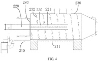
FIG. 4 is a cross-sectional view, taken along line A-A ofFIG. 3 ; -
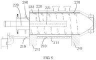
FIG. 5 is a cross-sectional view, taken along line B-B ofFIG. 3 ; -
FIG. 6 is a perspective view showing an internal of a mixing tank according to one embodiment; -
FIG. 7 is a side view of a mixing tank according to an embodiment; -
FIG. 8 is a top view of a plant according to an embodiment; and -
FIG. 9 is a cross-sectional view, taken along line A-A ofFIG. 8 . - Embodiments of the invention are described more fully hereinafter with reference to the accompanying drawings, in which preferred embodiments of the invention are shown. The various embodiments of the invention may, however, be embodied in many different forms and should not be construed as limited to the embodiments set forth herein. Rather, these embodiments are provided so that this disclosure will be thorough and complete, and will fully convey the scope of the invention to those skilled in the art.
- It will be understood that when an element is referred to as being "fixed" to another element, it can be directly fixed to the other element or intervening elements may be present. When an element is referred to as being "connected" or "coupled" to another element, it can be directly connected or coupled to the other element or intervening elements may be present. The terminology "perpendicular", "horizontal", "left", "right" and similar expressions herein are for the purpose of illustration, and not for a unique implemented mode.
- Unless otherwise defined, all terms used herein have the same meaning as commonly understood by one of ordinary skill in the art to which this invention belongs. Terms in the description of the connector are for the purpose of describing specific embodiments, and are not intend to limit the invention. As used herein, the term "and/or" includes any and all combinations of one or more of the associated listed items.
- As shown in
FIG. 1 , amixing plant 200 for composite particles is provided according to one embodiment, theplant 200 includes arotatable mixing tank 230, afixing bracket 240 for supportingaforementioned mixing tank 230, at least one heatconductive pipe 210, a primary heatconductive pipe 220, and apneumatic valve 250. - The
mixing tank 230 can be driven to rotate by a motor. For example, in one embodiment, opposite ends of themixing tank 230 are provided withtooth discs 231. Thetooth disc 231 is arranged along a peripheral direction of the end of themixing tank 230. Thetooth disc 231 is connected to the motor via a gear transmission mechanism. After an electric drive, themixing tank 230 is driven by the gear transmission mechanism to realize a rotation around a central axis of themixing tank 230, thereby accomplishing a stirring of the materials in an inner chamber of the mixing tank. - In the illustrated embodiment, aforementioned heat
conductive pipe 210 defines a plurality of hotair entrance holes 211 on a sidewall thereof facing a heat source. The primary heatconductive pipe 220 is in communication with an inner chamber of themixing tank 230. The primary heatconductive pipe 220 is in communication with the heatconductive pipe 210, the primary heatconductive pipe 220 and the heatconductive pipe 210 constitute an air communication passage. Thepneumatic valve 250 is located in the air communication passage. Thepneumatic valve 250 is configured to control an atmospheric pressure. When the atmospheric pressure in the air communication passage is too great, it can be detected by thepneumatic valve 250, and thepneumatic valve 250 is initiated to perform a decompression to the atmospheric pressure. - It shows that, in one embodiment, hot air close to a heat source can be inhaled into the air communication passage by the heat conductive pipe, and is introduced into the rotatable mixing tank by the primary heat conductive pipe, thereby achieving a heating, such heating method can provide a more homogeneous heating, and provide a drying treatment for the wet materials in the mixing tank. The heat source mentioned here can be any devices which can provide a high temperature gas, such as a heating furnace.
- As shown in
FIG. 1 andFIG. 2 , on basis of the structural foundation of above embodiment, in one embodiment, thefixing bracket 240 includes at least two supportingwalls 241, the supportingwall 241 defines a fixing hole which is provided for the at least one heatconductive pipe 210 extending through and fixing the heat conductive pipe to thefixing bracket 240. The plurality ofhot airs 211 are defined on a portion of the heatconductive pipe 210 which is located between the two supportingwalls 241. The two supportingwalls 241 support themixing tank 230 to create a distance from a supporting surface (e.g. the ground surface), the heat source (e.g. the heating furnace) is located within the distance, an occupying space can be saved, causing the plant to have a more compact structure. - In addition, in order to conveniently inhale the air or diffuse the air in the air communication passage, in one embodiment, both the primary heat
conductive pipe 220 and the heatconductive pipe 210 have hollow tubular shapes. And/or the primary heatconductive pipe 220 and the heatconductive pipe 210 are parallel arranged. For example, the primary heatconductive pipe 220 is arranged parallel to an axis of themixing tank 230. The hollow tubular shape mentioned here in the illustrated embodiment can be a hollow tubular structure which has a cross-section of any shape, such as a hollow circular tube, a hollow tube having a trapezoidal cross-section, a hollow elliptical tube, a hollow square tube. - In order to accelerate a diffusion of the hot air in the mixing tank, as shown in
FIG. 1 through FIG. 3 , in one embodiment, both the primary heatconductive pipe 220 and the heatconductive pipe 210 are hollow circular tubes. A diameter of the primary heatconductive pipe 220 is greater than a diameter of the heat conductive pipe. Apparently, the primary heatconductive pipe 220 can also adopt a structure which has a plurality of heat exchange tubes. For example, a plurality of heat exchange tubes are located in the mixing tank to form a primary radiating tube, the plurality of heat exchange tubes are in communication with the heatconductive pipe 210 to form the air communication passage. - In addition, in order to constantly heat the material in the mixing tank in a rotation process of the mixing tank, as shown in
FIG. 3 through FIG. 5 , in one embodiment, an end of themixing tank 230 is provided with a sealingcover 280. The sealingcover 280 defines a through hole thereon. The primary heatconductive pipe 220 extends through the through hole and into themixing tank 230. The through hole of the sealingcover 280 is connected to the primary heatconductive pipe 220 via abearing 270. In the illustrated embodiment, when themixing tank 230 rotates, a rotation of themixing tank 230 can be separated from the primary heatconductive pipe 220 by a limitation of thebearing 270, a following movement of the primary heatconductive pipe 220 accompanying to themixing tank 230 can be avoided. Apparently, in other embodiments, the primary heat conductive pipe is linked to the sealingcover 280 of the mixing tank for moving. - As shown in
FIG. 4 through FIG. 6 , on basis of the structural foundation of any one aforementioned embodiment, in one embodiment, an end of the primary heatconductive pipe 220 extends into themixing tank 230, and a portion of the primary heatconductive pipe 220 which extends into themixing tank 230 defines at least one row of hot air exhaust holes 221 along a longitudinal direction. The at least one row of hot air exhaust holes 221 is arranged along a longitudinal direction of the primary heatconductive pipe 220. Apparently, the portion of the primary heatconductive pipe 220 which extends into themixing tank 230 can also define at least one loop of hot air exhaust holes 221 along a peripheral direction. The pluralities of hot air exhaust holes 221 are mainly arranged to diffuse the hot air into the mixing tank rapidly, causing a heating to be more homogeneous. - As shown in
FIG. 1 through FIG. 9 , in one embodiment, a vertical height of the at least one heat conductive pipe is less than a vertical height of the primary heat conductive pipe. The vertical height mentioned here indicates a distance between an axis of the heat conductive pipe or an axis of the primary heat conductive pipe and the supporting surface (e.g. the ground surface). In the illustrated embodiment, a hot air self-diffusion principle can be utilized to enable the hot air to be delivered and diffused automatically in the air communication passage, without adopting external force to diffuse the hot air in the air communication passage. - As shown in
FIG. 5 through FIG. 9 , on basis of the structural foundation of any one aforementioned embodiment, in one embodiment, the air communication passage defines an exhaust throughhole 291 and includes a first connectingtube 293, a second connectingtube 292, the at least one heatconductive pipe 210, and the primary heatconductive pipe 220. The at least one heatconductive pipe 210 is in communication with the first connectingtube 293. The first connectingtube 293 is in communication with the exhaust throughhole 291. The first connectingtube 293 is further in communication with the primary heatconductive pipe 220 via the second connectingtube 292. Thepneumatic valve 250 is positioned on the second connectingtube 292. The first connectingtube 293 is a four-way adapter coupling, or a multi-way adapter coupling. In addition, as shown inFIG. 9 , the first connectingtube 293 and the second connectingtube 292 can be fixed or supported by thebracket 260, so as to fixedly support an air communitarian passage assembly outside of themixing tank 230. - As shown in
FIG. 5 andFIG. 6 , on basis of the structural foundation of any one aforementioned embodiment, in one embodiment, in order to accelerate a flowing of the hot air in the air communication passage, the plant further includes an air pump (not shown), the air pump is connected to the air communication passage, and configured to pump the hot air close to the heat source into the at least one heat conductive pipe via the hot air entrance holes, i.e. a negative pressure can be generated in the at least one heat conductive pipe by the air pump, thereby causing the hot air close to the heat source to be quickly inhaled into the at least one heat conductive pipe. - As shown in
FIG. 4 andFIG. 5 , on basis of the structural foundation of any one aforementioned embodiment, in one embodiment, themixing tank 230 further includes a plurality ofelongated members 232. The plurality ofelongated members 232 are arranged along an inner wall of themixing tank 230 and spaced from each other, and the plurality ofelongated members 232 are arranged in a spiral shape. Angles between eachelongated member 232 and the axis of themixing tank 230 are the same. Eachelongated member 232 extends from an end of themixing tank 230 to an opposite end of themixing tank 230. When themixing tank 230 rotates, theelongated member 232 follows and rotates to generate a wind force which blows into an inner of themixing tank 230 and inhales composite particles from the entrance holes into the inner. When themixing tank 230 rotates reversely, theelongated member 232 follows and rotates to generate a wind force which blows outside themixing tank 230, and composite particles are outputted from outlets. - In order to solve the problem of an uneven heat of the material in the mixing tank in the prior art, in one embodiment, a mixing plant for composite particles is provided. By providing a heat conductive pipe which defines a plurality of hot air entrance holes, the hot air close to a heat source is inhaled into an air communication passage constituted by the primary heat conductive pipe and the heat conductive pipe. When the primary heat conductive pipe is in communication with an inner chamber of the mixing tank, the hot air is introduced into the rotatable mixing tank by the primary heat conductive pipe, thereby achieving a heating, the heating method can provide a more homogeneous heating, and further causes the temperature in the mixing tank to be raised gradually, and enhances a controllability of the temperature in the mixing tank without additionally adding an electric heat tube circuit. An improvement cost for adding a heating function to the plant which does not have a heating function is low. In addition, a heat conduction and heat treatment of the whole mixing tank is eliminated, thereby a negative effect that causes damage to the housing of the mixing tank is avoided.
- Technical features of above embodiments can be combined arbitrarily, for simple, any combination of every technical feature in above embodiments is not all illustrated. However, the technical features which are not contradicted to each other may fall into the scope of the specification.
- Based upon aforementioned plant, in one embodiment, a heating method of a mixing tank for composite particles is provided, which includes: hot air close to the heat source is sucked into an air communication passage constituted by the primary heat conductive pipe and the heat conductive pipe, by providing a heat conductive pipe which defines a plurality of hot air entrance holes; the primary heat conductive pipe is in communication with an inner chamber of the mixing tank, thereby the hot air is introduced into the rotatable mixing tank by the primary heat conductive pipe. The structural configuration of the heat conductive pipe and the primary heat conductive pipe can be referred from aforementioned related illustration, and is not specific illustrated herein.
- The above are several embodiments of the present invention described in detail, and should not be deemed as limitations to the scope of the present invention. It should be noted that variations and improvements will become apparent to those skilled in the art to which the present invention pertains without departing from its spirit and scope. Therefore, the scope of the present invention is defined by the appended claims.
Claims (10)
- A mixing plant for composite particles, comprising:a rotatable mixing tank having an inner chamber;a fixing bracket for supporting the mixing tank;at least one heat conductive pipe, wherein the heat conductive pipe defines a plurality of hot air entrance holes on a sidewall thereof facing a heat source;a primary heat conductive pipe in communication with the inner chamber, wherein the primary heat conductive pipe is in communication with the heat conductive pipe to form an air communication passage; anda pneumatic valve located in the air communication passage.
- The plant according to claim 1, wherein the fixing bracket has at least two supporting walls, the supporting wall defines a fixing hole which is provided for the at least one heat conductive pipe extending through and fixing the heat conductive pipe to the fixing bracket, and the plurality of hot air entrance holes are defined on a portion of the heat conductive pipe which is located between the two supporting walls.
- The plant according to claim 1, wherein both the primary heat conductive pipe and the heat conductive pipe have hollow tubular shapes, and/or the primary heat conductive pipe and the heat conductive pipe are parallel arranged.
- The plant according to claim 1, wherein a diameter of the primary heat conductive pipe is greater than a diameter of the heat conductive pipe.
- The plant according to claim 1, wherein an end of the mixing tank is provided with a sealing cover, the sealing cover defines a through hole thereon, the primary heat conductive pipe extends through the through hole and into the mixing tank, the primary heat conductive pipe is located in the through hole of the sealing cover via a bearing.
- The plant according to claim 1, wherein an end of the primary heat conductive pipe extends into the mixing tank, and a portion of the primary heat conductive pipe which extends into the mixing tank defines at least one row of hot air exhaust holes arranged along a longitudinal direction, or a portion of the primary heat conductive pipe which extends into the mixing tank defines at least one loop of hot air exhaust holes along a peripheral direction.
- The plant according to claim 1, wherein a vertical height of the at least one heat conductive pipe is less than a vertical height of the primary heat conductive pipe.
- The plant according to claim 1, wherein the air communication passage further defines an exhaust through hole, the at least one heat conductive pipe is in communication with the first connecting tube, the first connecting tube is in communication with the exhaust through hole, and the first connecting tube is further in communication with the primary heat conductive pipe via the second connecting tube, the pneumatic valve is located on the second connecting tube.
- The plant according to claim 1, further comprising an air pump, wherein the air pump is connected to the air communication passage, and configured to pump hot air close to a heat source into the at least one heat conductive pipe via the hot air entrance holes
- A heating method of a mixing tank for composite particles, comprising:inhaling hot air close to a heat source into an air communication passage which is constituted by a primary heat conductive pipe and a heat conductive pipe, by providing a heat conductive pipe which defines a plurality of hot air entrance holes; andcommunicating the primary heat conductive pipe with an inner chamber of the mixing tank, thereby introducing the hot air into the rotatable mixing tank by the primary heat conductive pipe.
Applications Claiming Priority (2)
| Application Number | Priority Date | Filing Date | Title |
|---|---|---|---|
| CN201510763207.9A CN105268354B (en) | 2015-11-10 | 2015-11-10 | Synthesis particle mixing plant and its heating means |
| PCT/CN2016/105367 WO2017080493A1 (en) | 2015-11-10 | 2016-11-10 | Stirring apparatus for synthetic particles and heating method therefor |
Publications (3)
| Publication Number | Publication Date |
|---|---|
| EP3375510A1 true EP3375510A1 (en) | 2018-09-19 |
| EP3375510A4 EP3375510A4 (en) | 2019-07-17 |
| EP3375510B1 EP3375510B1 (en) | 2024-03-13 |
Family
ID=55138712
Family Applications (1)
| Application Number | Title | Priority Date | Filing Date |
|---|---|---|---|
| EP16863669.4A Active EP3375510B1 (en) | 2015-11-10 | 2016-11-10 | Stirring apparatus for synthetic particles and heating method therefor |
Country Status (3)
| Country | Link |
|---|---|
| EP (1) | EP3375510B1 (en) |
| CN (1) | CN105268354B (en) |
| WO (1) | WO2017080493A1 (en) |
Families Citing this family (7)
| Publication number | Priority date | Publication date | Assignee | Title |
|---|---|---|---|---|
| CN105268354B (en) * | 2015-11-10 | 2018-09-14 | 柏红梅 | Synthesis particle mixing plant and its heating means |
| CN108380108A (en) * | 2018-05-14 | 2018-08-10 | 辽宁科技大学 | A kind of dry particl mixing machine |
| CN110360581B (en) * | 2019-08-28 | 2020-08-11 | 扬州鑫科环保成套设备有限公司 | RTO heat accumulation formula burns burning furnace combustion chamber |
| CN110844411A (en) * | 2019-10-22 | 2020-02-28 | 穗农环保生物科技(深圳)有限公司 | Sealing door mechanism and garbage disposal equipment having the same |
| CN114292986B (en) * | 2022-01-19 | 2023-09-08 | 郭金福 | Temperature-control tempering container for wear-resistant steel balls |
| CN117753296B (en) * | 2023-11-16 | 2026-07-21 | 河南英利新材料有限公司 | System and method for controlling temperature of paste produced by prebaked anode |
| CN121499245A (en) * | 2025-11-06 | 2026-02-10 | 江苏松上科技有限公司 | A device and method for testing the compressive strength of recycled plastic granules |
Family Cites Families (15)
| Publication number | Priority date | Publication date | Assignee | Title |
|---|---|---|---|---|
| US4198761A (en) * | 1978-04-20 | 1980-04-22 | Societe pour la Recherche, l'Etude et Mise au Point de Tous Brevets, S.O.R.E.B. | Forced blowing method for fluids enabling thermal exchanges within a moving mass of material placed in a rotating cylinder |
| SU1662667A1 (en) * | 1989-04-18 | 1991-07-15 | Винницкий политехнический институт | Granulator |
| CN2123046U (en) * | 1991-06-12 | 1992-11-25 | 胡建国 | Rotary dryer |
| CN2237823Y (en) * | 1993-07-02 | 1996-10-16 | 阎广才 | Rotary tub drier |
| JP3738416B2 (en) * | 1999-09-30 | 2006-01-25 | 宇部テクノエンジ株式会社 | Stirrer |
| JP2007175610A (en) * | 2005-12-27 | 2007-07-12 | Sumitomo Chemical Co Ltd | Ventilation rotation device |
| CN100496688C (en) * | 2007-05-10 | 2009-06-10 | 云南昆船设计研究院 | Drum-type material loosening and temperature-increasing moisturizing device |
| US9326525B2 (en) * | 2008-06-05 | 2016-05-03 | Tsukasa Industry Co., Ltd. | Kneading device |
| CN201361541Y (en) * | 2008-12-27 | 2009-12-16 | 黄吉宽 | Drum-type heating agitator |
| DE102010036920A1 (en) * | 2010-08-09 | 2012-02-09 | Ullrich Heinz | Apparatus and method for producing pellets from biomass |
| CN203108484U (en) * | 2013-03-20 | 2013-08-07 | 长安大学 | A waste gas recycling device for asphalt mixture |
| CN203152380U (en) * | 2013-03-31 | 2013-08-28 | 厨师食品股份有限公司 | Vacuum mixing machine |
| CN203635126U (en) * | 2013-12-20 | 2014-06-11 | 玉门市玉海能源开发有限公司 | Pulping machine |
| CN205182601U (en) * | 2015-11-10 | 2016-04-27 | 柏红梅 | Synthetic agitated vessel for granule |
| CN105268354B (en) * | 2015-11-10 | 2018-09-14 | 柏红梅 | Synthesis particle mixing plant and its heating means |
-
2015
- 2015-11-10 CN CN201510763207.9A patent/CN105268354B/en active Active
-
2016
- 2016-11-10 EP EP16863669.4A patent/EP3375510B1/en active Active
- 2016-11-10 WO PCT/CN2016/105367 patent/WO2017080493A1/en not_active Ceased
Also Published As
| Publication number | Publication date |
|---|---|
| EP3375510A4 (en) | 2019-07-17 |
| EP3375510B1 (en) | 2024-03-13 |
| CN105268354B (en) | 2018-09-14 |
| WO2017080493A1 (en) | 2017-05-18 |
| CN105268354A (en) | 2016-01-27 |
Similar Documents
| Publication | Publication Date | Title |
|---|---|---|
| EP3375510B1 (en) | Stirring apparatus for synthetic particles and heating method therefor | |
| CN102341651B (en) | Door With A Built-In Burner For A Heating Appliance | |
| US9624944B2 (en) | Bladeless fan | |
| EP3093497A3 (en) | Blower | |
| JP2006519355A5 (en) | ||
| CN204757260U (en) | Air supply system and phytotron | |
| KR101523315B1 (en) | Heating Systems | |
| CN101975179B (en) | Fan structure | |
| CN205245171U (en) | Energy -conserving furnace end with gas mixing arrangement | |
| CN215930488U (en) | Tubular bale drying equipment | |
| EP2789926A1 (en) | Fan heater | |
| CN205182601U (en) | Synthetic agitated vessel for granule | |
| CN104061140A (en) | Fan | |
| CN203272184U (en) | Fan | |
| CN207070693U (en) | A kind of factory edible fungi mushroom room humidification, fresh air two-in-one system | |
| CN204862723U (en) | instant heating element | |
| CN204830455U (en) | Hot -blast conveyor of far infrared | |
| CN103954116A (en) | Fan type heat dissipation drying equipment | |
| CN203972844U (en) | Vertical Ladle-casting apparatus | |
| CN213578408U (en) | Uropoiesis is mattress drying device for nursing | |
| CN115529988A (en) | Fruit tree sapling cultivation room humiture automatically regulated equipment | |
| CN108516552A (en) | A kind of internal heat type absorbent charcoal activation furnace | |
| CN105201896A (en) | Fan bearing seat | |
| CN208916823U (en) | A kind of internal heat type absorbent charcoal activation furnace | |
| CN207057240U (en) | A kind of universal draft hood |
Legal Events
| Date | Code | Title | Description |
|---|---|---|---|
| STAA | Information on the status of an ep patent application or granted ep patent |
Free format text: STATUS: THE INTERNATIONAL PUBLICATION HAS BEEN MADE |
|
| PUAI | Public reference made under article 153(3) epc to a published international application that has entered the european phase |
Free format text: ORIGINAL CODE: 0009012 |
|
| STAA | Information on the status of an ep patent application or granted ep patent |
Free format text: STATUS: REQUEST FOR EXAMINATION WAS MADE |
|
| 17P | Request for examination filed |
Effective date: 20180608 |
|
| AK | Designated contracting states |
Kind code of ref document: A1 Designated state(s): AL AT BE BG CH CY CZ DE DK EE ES FI FR GB GR HR HU IE IS IT LI LT LU LV MC MK MT NL NO PL PT RO RS SE SI SK SM TR |
|
| AX | Request for extension of the european patent |
Extension state: BA ME |
|
| DAV | Request for validation of the european patent (deleted) | ||
| DAX | Request for extension of the european patent (deleted) | ||
| A4 | Supplementary search report drawn up and despatched |
Effective date: 20190619 |
|
| RIC1 | Information provided on ipc code assigned before grant |
Ipc: B01F 15/06 20060101ALI20190613BHEP Ipc: B01F 9/06 20060101ALI20190613BHEP Ipc: B01F 9/00 20060101AFI20190613BHEP Ipc: B01F 15/02 20060101ALI20190613BHEP Ipc: B01F 3/18 20060101ALI20190613BHEP |
|
| RAP1 | Party data changed (applicant data changed or rights of an application transferred) |
Owner name: BAI, HONGMEI |
|
| RIN1 | Information on inventor provided before grant (corrected) |
Inventor name: BAI, HONGMEI |
|
| STAA | Information on the status of an ep patent application or granted ep patent |
Free format text: STATUS: EXAMINATION IS IN PROGRESS |
|
| 17Q | First examination report despatched |
Effective date: 20211130 |
|
| REG | Reference to a national code |
Ref country code: DE Ref legal event code: R079 Free format text: PREVIOUS MAIN CLASS: B01F0009000000 Ref document number: 602016086339 Country of ref document: DE Ipc: B01F0023600000 |
|
| RIC1 | Information provided on ipc code assigned before grant |
Ipc: B01F 35/90 20220101ALI20230706BHEP Ipc: B01F 35/91 20220101ALI20230706BHEP Ipc: B01F 35/75 20220101ALI20230706BHEP Ipc: B01F 29/63 20220101ALI20230706BHEP Ipc: B01F 23/60 20220101AFI20230706BHEP |
|
| GRAP | Despatch of communication of intention to grant a patent |
Free format text: ORIGINAL CODE: EPIDOSNIGR1 |
|
| STAA | Information on the status of an ep patent application or granted ep patent |
Free format text: STATUS: GRANT OF PATENT IS INTENDED |
|
| INTG | Intention to grant announced |
Effective date: 20230922 |
|
| GRAS | Grant fee paid |
Free format text: ORIGINAL CODE: EPIDOSNIGR3 |
|
| GRAA | (expected) grant |
Free format text: ORIGINAL CODE: 0009210 |
|
| STAA | Information on the status of an ep patent application or granted ep patent |
Free format text: STATUS: THE PATENT HAS BEEN GRANTED |
|
| AK | Designated contracting states |
Kind code of ref document: B1 Designated state(s): AL AT BE BG CH CY CZ DE DK EE ES FI FR GB GR HR HU IE IS IT LI LT LU LV MC MK MT NL NO PL PT RO RS SE SI SK SM TR |
|
| P01 | Opt-out of the competence of the unified patent court (upc) registered |
Effective date: 20240207 |
|
| REG | Reference to a national code |
Ref country code: GB Ref legal event code: FG4D |
|
| REG | Reference to a national code |
Ref country code: CH Ref legal event code: EP |
|
| REG | Reference to a national code |
Ref country code: DE Ref legal event code: R096 Ref document number: 602016086339 Country of ref document: DE |
|
| REG | Reference to a national code |
Ref country code: IE Ref legal event code: FG4D |
|
| PG25 | Lapsed in a contracting state [announced via postgrant information from national office to epo] |
Ref country code: LT Free format text: LAPSE BECAUSE OF FAILURE TO SUBMIT A TRANSLATION OF THE DESCRIPTION OR TO PAY THE FEE WITHIN THE PRESCRIBED TIME-LIMIT Effective date: 20240313 |
|
| REG | Reference to a national code |
Ref country code: LT Ref legal event code: MG9D |
|
| PG25 | Lapsed in a contracting state [announced via postgrant information from national office to epo] |
Ref country code: GR Free format text: LAPSE BECAUSE OF FAILURE TO SUBMIT A TRANSLATION OF THE DESCRIPTION OR TO PAY THE FEE WITHIN THE PRESCRIBED TIME-LIMIT Effective date: 20240614 |
|
| REG | Reference to a national code |
Ref country code: NL Ref legal event code: MP Effective date: 20240313 |
|
| PG25 | Lapsed in a contracting state [announced via postgrant information from national office to epo] |
Ref country code: RS Free format text: LAPSE BECAUSE OF FAILURE TO SUBMIT A TRANSLATION OF THE DESCRIPTION OR TO PAY THE FEE WITHIN THE PRESCRIBED TIME-LIMIT Effective date: 20240613 Ref country code: HR Free format text: LAPSE BECAUSE OF FAILURE TO SUBMIT A TRANSLATION OF THE DESCRIPTION OR TO PAY THE FEE WITHIN THE PRESCRIBED TIME-LIMIT Effective date: 20240313 |
|
| PG25 | Lapsed in a contracting state [announced via postgrant information from national office to epo] |
Ref country code: ES Free format text: LAPSE BECAUSE OF FAILURE TO SUBMIT A TRANSLATION OF THE DESCRIPTION OR TO PAY THE FEE WITHIN THE PRESCRIBED TIME-LIMIT Effective date: 20240313 |
|
| PG25 | Lapsed in a contracting state [announced via postgrant information from national office to epo] |
Ref country code: RS Free format text: LAPSE BECAUSE OF FAILURE TO SUBMIT A TRANSLATION OF THE DESCRIPTION OR TO PAY THE FEE WITHIN THE PRESCRIBED TIME-LIMIT Effective date: 20240613 Ref country code: NO Free format text: LAPSE BECAUSE OF FAILURE TO SUBMIT A TRANSLATION OF THE DESCRIPTION OR TO PAY THE FEE WITHIN THE PRESCRIBED TIME-LIMIT Effective date: 20240613 Ref country code: LT Free format text: LAPSE BECAUSE OF FAILURE TO SUBMIT A TRANSLATION OF THE DESCRIPTION OR TO PAY THE FEE WITHIN THE PRESCRIBED TIME-LIMIT Effective date: 20240313 Ref country code: HR Free format text: LAPSE BECAUSE OF FAILURE TO SUBMIT A TRANSLATION OF THE DESCRIPTION OR TO PAY THE FEE WITHIN THE PRESCRIBED TIME-LIMIT Effective date: 20240313 Ref country code: GR Free format text: LAPSE BECAUSE OF FAILURE TO SUBMIT A TRANSLATION OF THE DESCRIPTION OR TO PAY THE FEE WITHIN THE PRESCRIBED TIME-LIMIT Effective date: 20240614 Ref country code: FI Free format text: LAPSE BECAUSE OF FAILURE TO SUBMIT A TRANSLATION OF THE DESCRIPTION OR TO PAY THE FEE WITHIN THE PRESCRIBED TIME-LIMIT Effective date: 20240313 Ref country code: ES Free format text: LAPSE BECAUSE OF FAILURE TO SUBMIT A TRANSLATION OF THE DESCRIPTION OR TO PAY THE FEE WITHIN THE PRESCRIBED TIME-LIMIT Effective date: 20240313 Ref country code: BG Free format text: LAPSE BECAUSE OF FAILURE TO SUBMIT A TRANSLATION OF THE DESCRIPTION OR TO PAY THE FEE WITHIN THE PRESCRIBED TIME-LIMIT Effective date: 20240313 |
|
| REG | Reference to a national code |
Ref country code: AT Ref legal event code: MK05 Ref document number: 1665234 Country of ref document: AT Kind code of ref document: T Effective date: 20240313 |
|
| PG25 | Lapsed in a contracting state [announced via postgrant information from national office to epo] |
Ref country code: SE Free format text: LAPSE BECAUSE OF FAILURE TO SUBMIT A TRANSLATION OF THE DESCRIPTION OR TO PAY THE FEE WITHIN THE PRESCRIBED TIME-LIMIT Effective date: 20240313 Ref country code: LV Free format text: LAPSE BECAUSE OF FAILURE TO SUBMIT A TRANSLATION OF THE DESCRIPTION OR TO PAY THE FEE WITHIN THE PRESCRIBED TIME-LIMIT Effective date: 20240313 |
|
| PG25 | Lapsed in a contracting state [announced via postgrant information from national office to epo] |
Ref country code: NL Free format text: LAPSE BECAUSE OF FAILURE TO SUBMIT A TRANSLATION OF THE DESCRIPTION OR TO PAY THE FEE WITHIN THE PRESCRIBED TIME-LIMIT Effective date: 20240313 |
|
| PG25 | Lapsed in a contracting state [announced via postgrant information from national office to epo] |
Ref country code: NL Free format text: LAPSE BECAUSE OF FAILURE TO SUBMIT A TRANSLATION OF THE DESCRIPTION OR TO PAY THE FEE WITHIN THE PRESCRIBED TIME-LIMIT Effective date: 20240313 |
|
| PG25 | Lapsed in a contracting state [announced via postgrant information from national office to epo] |
Ref country code: IS Free format text: LAPSE BECAUSE OF FAILURE TO SUBMIT A TRANSLATION OF THE DESCRIPTION OR TO PAY THE FEE WITHIN THE PRESCRIBED TIME-LIMIT Effective date: 20240713 |
|
| PG25 | Lapsed in a contracting state [announced via postgrant information from national office to epo] |
Ref country code: SM Free format text: LAPSE BECAUSE OF FAILURE TO SUBMIT A TRANSLATION OF THE DESCRIPTION OR TO PAY THE FEE WITHIN THE PRESCRIBED TIME-LIMIT Effective date: 20240313 Ref country code: PT Free format text: LAPSE BECAUSE OF FAILURE TO SUBMIT A TRANSLATION OF THE DESCRIPTION OR TO PAY THE FEE WITHIN THE PRESCRIBED TIME-LIMIT Effective date: 20240715 |
|
| PG25 | Lapsed in a contracting state [announced via postgrant information from national office to epo] |
Ref country code: EE Free format text: LAPSE BECAUSE OF FAILURE TO SUBMIT A TRANSLATION OF THE DESCRIPTION OR TO PAY THE FEE WITHIN THE PRESCRIBED TIME-LIMIT Effective date: 20240313 Ref country code: CZ Free format text: LAPSE BECAUSE OF FAILURE TO SUBMIT A TRANSLATION OF THE DESCRIPTION OR TO PAY THE FEE WITHIN THE PRESCRIBED TIME-LIMIT Effective date: 20240313 |
|
| PG25 | Lapsed in a contracting state [announced via postgrant information from national office to epo] |
Ref country code: AT Free format text: LAPSE BECAUSE OF FAILURE TO SUBMIT A TRANSLATION OF THE DESCRIPTION OR TO PAY THE FEE WITHIN THE PRESCRIBED TIME-LIMIT Effective date: 20240313 |
|
| PG25 | Lapsed in a contracting state [announced via postgrant information from national office to epo] |
Ref country code: PL Free format text: LAPSE BECAUSE OF FAILURE TO SUBMIT A TRANSLATION OF THE DESCRIPTION OR TO PAY THE FEE WITHIN THE PRESCRIBED TIME-LIMIT Effective date: 20240313 |
|
| PG25 | Lapsed in a contracting state [announced via postgrant information from national office to epo] |
Ref country code: SK Free format text: LAPSE BECAUSE OF FAILURE TO SUBMIT A TRANSLATION OF THE DESCRIPTION OR TO PAY THE FEE WITHIN THE PRESCRIBED TIME-LIMIT Effective date: 20240313 |
|
| PG25 | Lapsed in a contracting state [announced via postgrant information from national office to epo] |
Ref country code: SM Free format text: LAPSE BECAUSE OF FAILURE TO SUBMIT A TRANSLATION OF THE DESCRIPTION OR TO PAY THE FEE WITHIN THE PRESCRIBED TIME-LIMIT Effective date: 20240313 Ref country code: SK Free format text: LAPSE BECAUSE OF FAILURE TO SUBMIT A TRANSLATION OF THE DESCRIPTION OR TO PAY THE FEE WITHIN THE PRESCRIBED TIME-LIMIT Effective date: 20240313 Ref country code: RO Free format text: LAPSE BECAUSE OF FAILURE TO SUBMIT A TRANSLATION OF THE DESCRIPTION OR TO PAY THE FEE WITHIN THE PRESCRIBED TIME-LIMIT Effective date: 20240313 Ref country code: PT Free format text: LAPSE BECAUSE OF FAILURE TO SUBMIT A TRANSLATION OF THE DESCRIPTION OR TO PAY THE FEE WITHIN THE PRESCRIBED TIME-LIMIT Effective date: 20240715 Ref country code: PL Free format text: LAPSE BECAUSE OF FAILURE TO SUBMIT A TRANSLATION OF THE DESCRIPTION OR TO PAY THE FEE WITHIN THE PRESCRIBED TIME-LIMIT Effective date: 20240313 Ref country code: IS Free format text: LAPSE BECAUSE OF FAILURE TO SUBMIT A TRANSLATION OF THE DESCRIPTION OR TO PAY THE FEE WITHIN THE PRESCRIBED TIME-LIMIT Effective date: 20240713 Ref country code: EE Free format text: LAPSE BECAUSE OF FAILURE TO SUBMIT A TRANSLATION OF THE DESCRIPTION OR TO PAY THE FEE WITHIN THE PRESCRIBED TIME-LIMIT Effective date: 20240313 Ref country code: CZ Free format text: LAPSE BECAUSE OF FAILURE TO SUBMIT A TRANSLATION OF THE DESCRIPTION OR TO PAY THE FEE WITHIN THE PRESCRIBED TIME-LIMIT Effective date: 20240313 Ref country code: AT Free format text: LAPSE BECAUSE OF FAILURE TO SUBMIT A TRANSLATION OF THE DESCRIPTION OR TO PAY THE FEE WITHIN THE PRESCRIBED TIME-LIMIT Effective date: 20240313 |
|
| PG25 | Lapsed in a contracting state [announced via postgrant information from national office to epo] |
Ref country code: IT Free format text: LAPSE BECAUSE OF FAILURE TO SUBMIT A TRANSLATION OF THE DESCRIPTION OR TO PAY THE FEE WITHIN THE PRESCRIBED TIME-LIMIT Effective date: 20240313 |
|
| REG | Reference to a national code |
Ref country code: DE Ref legal event code: R097 Ref document number: 602016086339 Country of ref document: DE |
|
| PG25 | Lapsed in a contracting state [announced via postgrant information from national office to epo] |
Ref country code: IT Free format text: LAPSE BECAUSE OF FAILURE TO SUBMIT A TRANSLATION OF THE DESCRIPTION OR TO PAY THE FEE WITHIN THE PRESCRIBED TIME-LIMIT Effective date: 20240313 |
|
| PG25 | Lapsed in a contracting state [announced via postgrant information from national office to epo] |
Ref country code: DK Free format text: LAPSE BECAUSE OF FAILURE TO SUBMIT A TRANSLATION OF THE DESCRIPTION OR TO PAY THE FEE WITHIN THE PRESCRIBED TIME-LIMIT Effective date: 20240313 |
|
| PLBE | No opposition filed within time limit |
Free format text: ORIGINAL CODE: 0009261 |
|
| STAA | Information on the status of an ep patent application or granted ep patent |
Free format text: STATUS: NO OPPOSITION FILED WITHIN TIME LIMIT |
|
| PG25 | Lapsed in a contracting state [announced via postgrant information from national office to epo] |
Ref country code: DK Free format text: LAPSE BECAUSE OF FAILURE TO SUBMIT A TRANSLATION OF THE DESCRIPTION OR TO PAY THE FEE WITHIN THE PRESCRIBED TIME-LIMIT Effective date: 20240313 |
|
| 26N | No opposition filed |
Effective date: 20241216 |
|
| PG25 | Lapsed in a contracting state [announced via postgrant information from national office to epo] |
Ref country code: SI Free format text: LAPSE BECAUSE OF FAILURE TO SUBMIT A TRANSLATION OF THE DESCRIPTION OR TO PAY THE FEE WITHIN THE PRESCRIBED TIME-LIMIT Effective date: 20240313 |
|
| REG | Reference to a national code |
Ref country code: CH Ref legal event code: PL |
|
| PG25 | Lapsed in a contracting state [announced via postgrant information from national office to epo] |
Ref country code: MC Free format text: LAPSE BECAUSE OF FAILURE TO SUBMIT A TRANSLATION OF THE DESCRIPTION OR TO PAY THE FEE WITHIN THE PRESCRIBED TIME-LIMIT Effective date: 20240313 |
|
| PG25 | Lapsed in a contracting state [announced via postgrant information from national office to epo] |
Ref country code: LU Free format text: LAPSE BECAUSE OF NON-PAYMENT OF DUE FEES Effective date: 20241110 |
|
| REG | Reference to a national code |
Ref country code: CH Ref legal event code: PL |
|
| GBPC | Gb: european patent ceased through non-payment of renewal fee |
Effective date: 20241110 |
|
| PG25 | Lapsed in a contracting state [announced via postgrant information from national office to epo] |
Ref country code: CH Free format text: LAPSE BECAUSE OF NON-PAYMENT OF DUE FEES Effective date: 20241130 |
|
| REG | Reference to a national code |
Ref country code: BE Ref legal event code: MM Effective date: 20241130 |
|
| PG25 | Lapsed in a contracting state [announced via postgrant information from national office to epo] |
Ref country code: BE Free format text: LAPSE BECAUSE OF NON-PAYMENT OF DUE FEES Effective date: 20241130 Ref country code: GB Free format text: LAPSE BECAUSE OF NON-PAYMENT OF DUE FEES Effective date: 20241110 |
|
| PG25 | Lapsed in a contracting state [announced via postgrant information from national office to epo] |
Ref country code: IE Free format text: LAPSE BECAUSE OF NON-PAYMENT OF DUE FEES Effective date: 20241110 |
|
| PGFP | Annual fee paid to national office [announced via postgrant information from national office to epo] |
Ref country code: DE Payment date: 20251118 Year of fee payment: 10 |
|
| PGFP | Annual fee paid to national office [announced via postgrant information from national office to epo] |
Ref country code: FR Payment date: 20251117 Year of fee payment: 10 |
|
| PG25 | Lapsed in a contracting state [announced via postgrant information from national office to epo] |
Ref country code: HU Free format text: LAPSE BECAUSE OF FAILURE TO SUBMIT A TRANSLATION OF THE DESCRIPTION OR TO PAY THE FEE WITHIN THE PRESCRIBED TIME-LIMIT; INVALID AB INITIO Effective date: 20161110 |
|
| PG25 | Lapsed in a contracting state [announced via postgrant information from national office to epo] |
Ref country code: CY Free format text: LAPSE BECAUSE OF FAILURE TO SUBMIT A TRANSLATION OF THE DESCRIPTION OR TO PAY THE FEE WITHIN THE PRESCRIBED TIME-LIMIT; INVALID AB INITIO Effective date: 20161110 |
|
| PG25 | Lapsed in a contracting state [announced via postgrant information from national office to epo] |
Ref country code: TR Free format text: LAPSE BECAUSE OF FAILURE TO SUBMIT A TRANSLATION OF THE DESCRIPTION OR TO PAY THE FEE WITHIN THE PRESCRIBED TIME-LIMIT Effective date: 20240313 |