EP3375468A1 - Medical injector with ratcheting plunger - Google Patents
Medical injector with ratcheting plunger Download PDFInfo
- Publication number
- EP3375468A1 EP3375468A1 EP18169323.5A EP18169323A EP3375468A1 EP 3375468 A1 EP3375468 A1 EP 3375468A1 EP 18169323 A EP18169323 A EP 18169323A EP 3375468 A1 EP3375468 A1 EP 3375468A1
- Authority
- EP
- European Patent Office
- Prior art keywords
- actuator
- plunger
- medical injector
- relative
- displacement
- Prior art date
- Legal status (The legal status is an assumption and is not a legal conclusion. Google has not performed a legal analysis and makes no representation as to the accuracy of the status listed.)
- Granted
Links
- 238000006073 displacement reaction Methods 0.000 claims abstract description 70
- 239000003814 drug Substances 0.000 claims abstract description 21
- 230000033001 locomotion Effects 0.000 claims description 27
- 230000002441 reversible effect Effects 0.000 claims description 8
- 230000036961 partial effect Effects 0.000 description 10
- 238000002347 injection Methods 0.000 description 8
- 239000007924 injection Substances 0.000 description 8
- 238000000034 method Methods 0.000 description 5
- 230000000670 limiting effect Effects 0.000 description 4
- 230000005540 biological transmission Effects 0.000 description 3
- 230000006870 function Effects 0.000 description 3
- 229940079593 drug Drugs 0.000 description 2
- 230000000694 effects Effects 0.000 description 2
- 229940090048 pen injector Drugs 0.000 description 2
- 230000002829 reductive effect Effects 0.000 description 2
- 230000000994 depressogenic effect Effects 0.000 description 1
- 230000002452 interceptive effect Effects 0.000 description 1
- 230000014759 maintenance of location Effects 0.000 description 1
- 239000000463 material Substances 0.000 description 1
- 238000000926 separation method Methods 0.000 description 1
- 229920001169 thermoplastic Polymers 0.000 description 1
- 239000004416 thermosoftening plastic Substances 0.000 description 1
Images


Classifications
-
- A—HUMAN NECESSITIES
- A61—MEDICAL OR VETERINARY SCIENCE; HYGIENE
- A61M—DEVICES FOR INTRODUCING MEDIA INTO, OR ONTO, THE BODY; DEVICES FOR TRANSDUCING BODY MEDIA OR FOR TAKING MEDIA FROM THE BODY; DEVICES FOR PRODUCING OR ENDING SLEEP OR STUPOR
- A61M5/00—Devices for bringing media into the body in a subcutaneous, intra-vascular or intramuscular way; Accessories therefor, e.g. filling or cleaning devices, arm-rests
- A61M5/178—Syringes
- A61M5/31—Details
- A61M5/315—Pistons; Piston-rods; Guiding, blocking or restricting the movement of the rod or piston; Appliances on the rod for facilitating dosing ; Dosing mechanisms
- A61M5/31533—Dosing mechanisms, i.e. setting a dose
- A61M5/31545—Setting modes for dosing
- A61M5/31548—Mechanically operated dose setting member
- A61M5/3155—Mechanically operated dose setting member by rotational movement of dose setting member, e.g. during setting or filling of a syringe
- A61M5/31551—Mechanically operated dose setting member by rotational movement of dose setting member, e.g. during setting or filling of a syringe including axial movement of dose setting member
-
- A—HUMAN NECESSITIES
- A61—MEDICAL OR VETERINARY SCIENCE; HYGIENE
- A61M—DEVICES FOR INTRODUCING MEDIA INTO, OR ONTO, THE BODY; DEVICES FOR TRANSDUCING BODY MEDIA OR FOR TAKING MEDIA FROM THE BODY; DEVICES FOR PRODUCING OR ENDING SLEEP OR STUPOR
- A61M5/00—Devices for bringing media into the body in a subcutaneous, intra-vascular or intramuscular way; Accessories therefor, e.g. filling or cleaning devices, arm-rests
- A61M5/178—Syringes
- A61M5/31—Details
- A61M5/315—Pistons; Piston-rods; Guiding, blocking or restricting the movement of the rod or piston; Appliances on the rod for facilitating dosing ; Dosing mechanisms
- A61M5/31533—Dosing mechanisms, i.e. setting a dose
- A61M5/31545—Setting modes for dosing
- A61M5/31548—Mechanically operated dose setting member
- A61M5/3155—Mechanically operated dose setting member by rotational movement of dose setting member, e.g. during setting or filling of a syringe
- A61M5/31553—Mechanically operated dose setting member by rotational movement of dose setting member, e.g. during setting or filling of a syringe without axial movement of dose setting member
-
- A—HUMAN NECESSITIES
- A61—MEDICAL OR VETERINARY SCIENCE; HYGIENE
- A61M—DEVICES FOR INTRODUCING MEDIA INTO, OR ONTO, THE BODY; DEVICES FOR TRANSDUCING BODY MEDIA OR FOR TAKING MEDIA FROM THE BODY; DEVICES FOR PRODUCING OR ENDING SLEEP OR STUPOR
- A61M5/00—Devices for bringing media into the body in a subcutaneous, intra-vascular or intramuscular way; Accessories therefor, e.g. filling or cleaning devices, arm-rests
- A61M5/178—Syringes
- A61M5/31—Details
- A61M5/315—Pistons; Piston-rods; Guiding, blocking or restricting the movement of the rod or piston; Appliances on the rod for facilitating dosing ; Dosing mechanisms
- A61M5/31565—Administration mechanisms, i.e. constructional features, modes of administering a dose
- A61M5/31576—Constructional features or modes of drive mechanisms for piston rods
- A61M5/31578—Constructional features or modes of drive mechanisms for piston rods based on axial translation, i.e. components directly operatively associated and axially moved with plunger rod
- A61M5/3158—Constructional features or modes of drive mechanisms for piston rods based on axial translation, i.e. components directly operatively associated and axially moved with plunger rod performed by axially moving actuator operated by user, e.g. an injection button
-
- A—HUMAN NECESSITIES
- A61—MEDICAL OR VETERINARY SCIENCE; HYGIENE
- A61M—DEVICES FOR INTRODUCING MEDIA INTO, OR ONTO, THE BODY; DEVICES FOR TRANSDUCING BODY MEDIA OR FOR TAKING MEDIA FROM THE BODY; DEVICES FOR PRODUCING OR ENDING SLEEP OR STUPOR
- A61M5/00—Devices for bringing media into the body in a subcutaneous, intra-vascular or intramuscular way; Accessories therefor, e.g. filling or cleaning devices, arm-rests
- A61M5/178—Syringes
- A61M5/31—Details
- A61M5/315—Pistons; Piston-rods; Guiding, blocking or restricting the movement of the rod or piston; Appliances on the rod for facilitating dosing ; Dosing mechanisms
- A61M5/31565—Administration mechanisms, i.e. constructional features, modes of administering a dose
- A61M5/3159—Dose expelling manners
- A61M5/31593—Multi-dose, i.e. individually set dose repeatedly administered from the same medicament reservoir
-
- A—HUMAN NECESSITIES
- A61—MEDICAL OR VETERINARY SCIENCE; HYGIENE
- A61M—DEVICES FOR INTRODUCING MEDIA INTO, OR ONTO, THE BODY; DEVICES FOR TRANSDUCING BODY MEDIA OR FOR TAKING MEDIA FROM THE BODY; DEVICES FOR PRODUCING OR ENDING SLEEP OR STUPOR
- A61M5/00—Devices for bringing media into the body in a subcutaneous, intra-vascular or intramuscular way; Accessories therefor, e.g. filling or cleaning devices, arm-rests
- A61M5/178—Syringes
- A61M5/31—Details
- A61M5/315—Pistons; Piston-rods; Guiding, blocking or restricting the movement of the rod or piston; Appliances on the rod for facilitating dosing ; Dosing mechanisms
- A61M5/31565—Administration mechanisms, i.e. constructional features, modes of administering a dose
- A61M5/31576—Constructional features or modes of drive mechanisms for piston rods
- A61M5/31578—Constructional features or modes of drive mechanisms for piston rods based on axial translation, i.e. components directly operatively associated and axially moved with plunger rod
- A61M5/31581—Constructional features or modes of drive mechanisms for piston rods based on axial translation, i.e. components directly operatively associated and axially moved with plunger rod performed by rotationally moving or pivoting actuator operated by user, e.g. an injection lever or handle
Definitions
- This invention relates to displaceable medical injector plungers and, more particularly, to ratcheting medical injector plungers.
- Medical injectors are well known in the art, including syringes and pen injectors. Medical injectors typically include a plunger for advancing one or more stoppers in delivering a medicament during an injection. Although it is known in the prior art to provide syringe plungers with teeth or other features to prevent retraction and re-use after an initial injection, syringe plungers are typically actuated through direct application of linear force. Dose size is a direct function of plunger displacement. It may be difficult to control linear displacement of the plunger, thus resulting in difficulty over control of dose size.
- a lead screw or rotating plunger is provided which is mechanically coupled to a dose-setting knob or other actuator through a series of mechanical connections.
- the typical pen injector mechanism is fairly complex and consists of multiple cooperating parts. For costs reasons and simplicity of use, a minimum number of working parts is desired.
- a plunger for a medical injector which may be controllably advanced with a minimum number of cooperating parts.
- a medical injector including a body having a distal end and a proximal end, and a plunger displaceably disposed in the body.
- the plunger includes a plurality of spaced-apart ratchet teeth disposed along the length thereof. The plunger selectively displaces a stopper to dispense a medicament from said medical injector.
- the medical injector also includes an indexer disposed within the body to engage the plunger to permit distal displacement of the plunger and substantially prevent proximal displacement of the plunger, an actuator having an engagement portion to engage the plunger to permit proximal displacement of the actuator relative to the plunger and substantially prevent distal displacement of the actuator relative to the plunger, and a rotating member for proximally displacing the engagement portion relative to the plunger and the body.
- an indexer disposed within the body to engage the plunger to permit distal displacement of the plunger and substantially prevent proximal displacement of the plunger
- an actuator having an engagement portion to engage the plunger to permit proximal displacement of the actuator relative to the plunger and substantially prevent distal displacement of the actuator relative to the plunger
- a rotating member for proximally displacing the engagement portion relative to the plunger and the body.
- the actuator Upon distal displacement of the actuator relative to the body from the ready state, the actuator engages one or more of the ratchet teeth to distally displace the plunger relative to the indexer to distally displace the stopper to dispense medicament from the medical injector.
- a medical injector including a body having a distal end and a proximal end, and a plunger displaceably disposed in the body.
- the plunger includes a plurality of spaced-apart ratchet teeth disposed along the length thereof.
- the plunger selectively displaces a stopper to dispense a medicament from the medical injector.
- the medical injector also includes an indexer disposed within the body to engage the plunger to permit distal displacement of the plunger and substantially prevent proximal displacement of the plunger.
- the medical injector additionally includes actuating means for actuating the medical device, the actuating means having engagement means for engaging the plunger to permit proximal displacement of the actuating means relative to the plunger and substantially prevent distal displacement of the actuating means relative to the plunger. Further, the medical injector includes rotating means for proximally displacing the engagement means relative to the plunger and the body. Upon proximal displacement of the actuating means relative to the body to a ready state, one or more of the ratchet teeth bypass the engagement means to proximally displace the actuating means relative to the plunger.
- the actuating means Upon distal displacement of the actuating means relative to the body from the ready state, the actuating means engages one or more of the ratchet teeth to distally displace the plunger relative to the indexer to distally displace the stopper to dispense medicament from the medical injector.
- the foregoing and/or other aspects of the present invention are also achieved by providing a method of injecting a medicament from a medical injector having a body with distal and proximate ends.
- the method includes the operations of permitting distal displacement of a plunger with respect to the body and substantially preventing proximal displacement of the plunger with respect to the body, and permitting proximal displacement of an actuator relative to the plunger and substantially preventing distal displacement of the actuator relative to the plunger.
- the method also includes the operations of rotating a rotating member to proximally displace the actuator relative to the body to a ready state, thereby proximally displacing the actuator relative to the plunger, and distally displacing the actuator relative to the body from the ready state, thereby engaging the plunger and distally displacing the plunger relative to the body to dispense medicament from the medical injector.
- a medical injector 10 is shown having a ratchetable plunger 12 provided therewith.
- the medical injector 10 may be of various forms, including being a syringe or pen injector.
- the medical injector 10 is particularly well-suited for administering at least one fixed dose, and is even better suited for administering a series of fixed doses.
- the medical injector 10 may be configured in any way known to be compatible with the plunger 12 as described herein.
- the medical injector 10 may include a reservoir 14 for accommodating an injectable medicament, which may be a drug cartridge, or which may be formed directly in the medical injector 10.
- the reservoir 14 may have one or more stoppers 16 associated therewith as known in the art.
- the medical injector 10 may also be provided with a needle 18 for injection which may be removably attached or affixed to the medical injector 10 such as in a "staked" arrangement.
- the plunger 12 is elongated and generally flat.
- a plurality of spaced-apart ratchet teeth 20 are disposed along the length of the plunger 12.
- the plunger 12 includes a plate-shaped body 22 having opposing first and second faces 24, 26.
- the ratchet teeth 20 are disposed on the first face 24 and, in a further preferred arrangement, also on the second face 26.
- the ratchet teeth 20 on the first and second faces 24, 26 are axially aligned along the length of the plunger 12.
- the ratchet teeth 20 are configured to permit unidirectional movement of the plunger 12.
- the ratchet teeth 20 are preferably saw-tooth shaped having a ramped surface 28 and a shoulder stop 30.
- the ramped surfaces 28 of the ratchet teeth 20 on both the first and second surfaces 24, 26 are oriented to face in the same general direction.
- the shoulder stops 30 extend transversely from the first and second faces 24, 26, preferably at a substantially perpendicular orientation.
- the plunger 12 may also have one or more rails 27 extending from the first face 24 and/or the second face 26.
- the rails 27 may be formed to slide through one or more corresponding shape-mating slots formed in the medical injector 10.
- the rails 27 may provide stability during use, particularly during translation of the plunger 12.
- the plunger 12 is disposed in a body 32 of the medical injector 10.
- the body 32 includes a distal end 34, located to be directed toward a patient during an injection, and a proximal end 36, located to be away from a patient during an injection ( Figure 1 ).
- the medical injector 10 is configured to permit the plunger 12 to move unidirectionally therein in a distal direction toward the distal end 34, but not in a proximal direction toward the proximal end 36.
- at least one indexer 38 is provided formed to engage the plunger 12.
- the indexer 38 is configured to allow the plunger 12 to displace distally toward the distal end 34 of the body 32 but not proximally toward the proximal end 36 of the body 32.
- the indexer 38 includes a deflectable pawl 40 which, as shown schematically in Figure 3 , includes a ramped engagement surface 42 and an outward facing stop surface 44.
- the indexer 38 is outwardly deflectable to permit the engagement surface 42 to ascend the ramped surface 28 of an individual of the ratchet teeth 20 with the plunger 12 moving distally relative thereto. With sufficient distal movement, the indexer 38 bypasses the ratchet teeth 12, and under inherent resilience of the indexer 38, snaps inwardly such that the stop surface 44 is aligned with the shoulder stop 30.
- the stop surface 44 is formed to be generally parallel to the shoulder stop 30.
- a pair of the indexers 38 are provided so as to act against the ratchet teeth 20 located on both the first and second faces 24, 26, as shown in Figures 4-6 . It is further preferred that a pair of the indexers 38 be provided which are axially aligned thus providing a pinching effect to the plunger 12. This pinching effect may provide a stable holding force for the plunger 12.
- the indexer 38 may be formed to be deflectable through inherent resilience, such as through material selection (e.g., being formed of a thermoplastic).
- the indexer 38 may include a cantilevered arm 46 which permits deflection of the associated pawl 40.
- the indexer 38 is formed to have a natural, unbiased state as shown in Figures 4-6 , where the indexer 38 is positioned to act against the shoulder stop 30 of the ratchet teeth 20.
- the cantilevered arm 46 is formed with sufficient internal memory to provide the unbiased state for the indexer 38.
- the medical injector 10 also includes an actuator 48 having an engagement portion 50 formed to engage one or more of the ratchet teeth 20.
- the engagement portion 50 preferably includes an engagement pawl 52 having a ramped engagement surface 54 and an outward facing stop surface 56 configured like the pawl 40 described above.
- two of the engagement portions 50 are provided located to engage the ratchet teeth 20 located on the first and second faces 24, 26.
- the plunger 12 is positioned to engage one of the stoppers 16.
- the actuator 48 is moved to a ready state, with the engagement portion 50 moving proximally.
- the indexer 38 prevents proximal movement of the plunger 12, thus allowing the actuator 48 to move proximally relative to the plunger 12.
- the engagement portion 50 bypasses one or more of the ratchet teeth 20.
- the actuator 48 is displaced sufficiently to achieve a ready state.
- the actuator 48 is displaced from the ready state with distal movement of the engagement portion 50.
- the engagement portion 50 engages one or more of the ratchet teeth 20, particularly with interfering engagement between the shoulder stop 30 and the stop surface 56.
- the engagement portion 50 engages the next distal ratchet tooth 20.
- Distal movement of the engagement portion 50 causes the plunger 12 to move distally therewith.
- Distal movement of the plunger 12 causes distal advancement of the stopper 16 in causing an injection to be administered.
- the ratchet teeth 20 are able to bypass the indexer 38 in the distal direction.
- the size of a dose to be administered by the medical injector 10 is a function of the spacing between the ratchet teeth 20 and/or the amount of proximal displacement of the engagement portion 50 relative to the ratchet teeth 20 with the actuator 48 moving to a ready state.
- one or more keys 58 may be defined on the medical injector 10 and/or the actuator 48 which are formed to nest within and slide along corresponding channels 60 formed in the medical injector 10 and/or the actuator 48. As shown in Figures 4-6 , it is preferred that the keys 58 be formed on the actuator 48 and the channels 60 be formed in the medical injector 10. With reference to Figure 4 , the keys 58 are at the distal end of the channel 60, prior to use.
- the keys 58 With proximal displacement of the actuator 48, the keys 58 are proximally advanced in the channels 60 to a proximal-most position corresponding to the ready state of the actuator 48.
- the length of the travel of the keys 58 in the channels 60 restricts the range of movement of the actuator 48 in defining the size of the dose administrable by the medical injector 10.
- the keys 58 are advanced distally with the actuator 48 during use to a distal-most position.
- the actuator 48 shown in Figures 4-6 is a linear slide actuator which applies force directly to the plunger 12.
- the actuator 48 may be of various configurations.
- the actuator 48 may include a rocker 62 pivotally mounted thereto.
- the rocker 62 is frame-shaped, having a first end 64 for pivotal mounting to the actuator 48 and a second opposing end 66 for pivotally mounting to the medical injector 10.
- the engagement portion 50 is located between the first and second ends 64, 66.
- two of the engagement portions 50 may be provided to coact with the ratchet teeth 20 being located on the first and second faces 24, 26.
- the spacing between the first and second ends 64, 66 affects force transmission from the actuator 48 to the plunger 12 particularly in the generation of torque.
- the actuator 48 is shown in an initial pre-use state with the rocker 62 being inclined distally.
- the actuator 48 has been advanced to the ready state with the rocker 62 having been drawn proximally with rotation about the second end 66 so as to be inclined in a proximal direction.
- the engagement portion 50 bypasses one or more of the ratchet teeth 20 in the same manner as described above.
- the actuator 48 is displaced from the ready state to cause actuation of the medical injector 10.
- the rocker 62 is caused to advance distally about the second end 66 with the engagement portion 50 causing the plunger 12 to also advance distally. Dose size may be restricted both by the key 58/channel 60 arrangement described above and/or by the range of motion of the rocker 62.
- the rocker 62 may be directly coupled to the actuator 48, as shown in Figures 9-11 .
- a multi-link arrangement may be used to couple the rocker 62 to the actuator 48.
- one or more links 68 may be connected between the rocker 62 and the actuator 48 to provide force for displacement thereof. Any arrangement of the links 68 may be utilized which transmits force from the actuator 48 to the rocker 62.
- two of the links 68 (68A, 68B) are utilized with the link 68Abeing pivotally connected to the actuator 48 and pivotally connected to the link 68B, and with the link 68B being pivotally connected to the link 68A and pivotally connected to the rocker 62.
- the links 68A, 68B collectively transmit force to the rocker 62.
- the actuator 48 may be arranged to be non-linearly displaced. As shown in Figures 15-17 , the actuator 48 may be formed to pivot about a fulcrum 70. With the actuator 48 pivoting outwardly from the medical injector 10 about the fulcrum 70, the engagement portion 50 is caused to be displaced proximally. Conversely, inward pivoting of the actuator 48 about the fulcrum 70 causes distal displacement of the engagement portion 50. The engagement portion 50 coacts with the plunger 12 in the same manner as described above.
- the medical injector 10 is shown in a pre-use state.
- a grip ring or pad 72 may be provided which extends radially outwardly from the medical injector 10 to facilitate displacement of the actuator 48.
- the actuator 48 is pivoted to a ready state as shown in Figure 17 .
- the actuator 48 is pivoted inwardly from the ready state, as shown by the arrow in Figure 17 .
- the size of the dose may be fixed with the actuator 48 being pivotable by limiting the range of rotation of the actuator 48.
- Aportion 74 of the medical injector 10 may be configured to limit the range of rotation of the actuator 48, particularly outward rotation, such limited range corresponding to the ready state.
- the actuator 48 may be formed as a linear slide actuator, but configured to accept a non-linear force to adjust the actuator 48 to the ready state.
- the actuator 48 may include a first portion 48A, formed in accordance with the description above.
- the actuator 48 may include a rotatable second portion 48B coupled to the first portion 48A so as to be rotatable relative thereto. This arrangement permits rotational adjustment of the actuator 48 to the ready state. Rotational adjustment is typical of pen-type injectors and may be preferred by some users.
- the second portion 48B is accessible exteriorly of the medical injector 10 so as to be engageable from the outside by a user; particularly, the second portion 48B extends proximally from the proximal end 36 of the body 32.
- the first and second portions 48A, 48B are rotatably coupled in any known manner.
- the second portion 48B may be formed with a continuous ring 80 seated in channel 82 of the first portion 48A.
- the ring 80 is sized and shaped to rotate freely within the channel 82 with the first and second portions 48A, 48B being axially fixed to move together.
- the ring 80 and the channel 82 may be reversed on the first and second portions 48A, 48B.
- a groove 84 is formed about an exterior of the second portion 48B.
- One or more keys 86 are located on surrounding portions of the medical injector 10, e.g., on the body 32, about the second portion 48B positioned and sized to be seated in the groove 84 so as to be moveable along the length thereof.
- the length of the groove 84 delimits the extent of rotation of the second portion 48B.
- the groove 84 is at least partially helical so as to have a screw thread shape.
- the key(s) 86 may be located on the exterior of the second portion 48B and the corresponding groove 84 may be formed on surrounding portions of the medical injector 10.
- Rotation of the second portion 48B in a first rotational direction results in proximal displacement of the first and second portions 48A, 48B with corresponding proximal displacement of the engagement portion 50 to the ready state.
- rotation of the second portion 48B results in proximal displacement thereof and, in concert, proximal displacement of the first portion 48A and of the engagement portion 50.
- the first portion 48A is non-rotatably displaced proximally.
- the length of the groove 84 limits the extent of rotation of the second portion 48B thereby limiting the dose that may be administered.
- the dose may be administered by pressing the second portion 48B, which results in distal advancement of the second portion 48B and, correspondingly, distal non-rotating advancement of the first portion 48 along with the engagement portion 50.
- the second portion 48B With distal advancement of the second portion 48B, it is preferred that the second portion 48B be advanced linearly without rotation. To this end, it is preferred that the groove 84 be formed with a first helical portion 84a and a second axial portion 84b extending from the first helical portion 84a generally parallel to the longitudinal axis of the second portion 48B.
- the one or more keys 86 traverse the first helical portion 84a with rotation of the second portion 48B in a proximal direction.
- Elbow 88 is defined at the junction of the first helical portion 84a and the second axial portion 84b which limits the extent of rotation and, thus, proximal displacement of the second portion 48B.
- the elbow 88 defines the ready position of the actuator 48.
- the second portion 48B is depressed and caused to advance distally linearly without rotation with the one or more keys 86 traversing the second axial portion 84b. This, in turn, causes distal advancement of the first portion 48A and distal advancement of the plunger 12 through engagement with the engagement portion 50.
- the linear displacement of the second portion 48B permits force applied thereto to be fully transmitted in one axial direction, without resolution into two or more components. As such, the full force of actuation applied to the second portion 48B is transmitted to the actuator 48.
- a single set of the first helical portion and the second axial portion 84a, 84b may be utilized.
- the groove 84 may be extended such that a secondary helical portion 84a' may extend directly from the terminus of the second axial portion 84b which extends into a secondary axial portion 84b' and so forth as needed.
- a series of the first helical portions 84a and second axial portions 84b may be defined continuously about the second portion 48B to facilitate multiple dosing.
- more than one groove 84 may be utilized with a corresponding set of one or more keys 86.
- one or more of the grooves 84 and one or more of the keys 86 may be located on the second portion 48B and/or surrounding portions of the medical injector 10.
- one or more detents 90 may be formed on the second portion 48B formed to snap engage one or more locating channels 92 formed on the medical injector 10 about the second portion 48B, such as on the body 32.
- a locating channel 92 is located corresponding to the second portion 48B being in the ready position, and such a ready position locating channel 92 is elongated such that the detent 90 may be displaced along the length thereof with the second portion 48B during dose administration.
- the detent(s) 90 may be formed on the medical injector 10 and the locating channels may be formed on the second portion 48B.
- a locking tab 94 is provided on the second portion 48B which is configured to snap engage into a locking channel 96 at a position coinciding with an end of the injection (e.g., position coinciding with the one or more keys 86 reaching the terminus of the second axial portion 84b at the end of a dosing stroke).
- Axial movement of the second portion 48B is thus limited.
- the locking channel 96 may be configured to permit rotation of the locking tab 94 for separation therefrom with rotation of the second portion 48B in preparing for a subsequent dose.
- the locking channel 96 is formed on a surrounding portion of the medical injector 10, such as on the body 32.
- the locking tab 94 may be formed on the medical injector 10 and the locking channel 96 may be provided on the second portion 48B.
- the second portion 48B may be allowed to rotate during distal advancement of the second portion 48B with the one or more keys 86 traveling along the groove 84.
- the second portion 48B may be rotated to any location along the groove 84 (84a) to set a dose with reverse rotation along the groove 84 (84a) permitting dosing.
- a scale, or other index, as known in the art may be provided to correspond to rotational displacement of the second portion 48B to provide indication of the set dose amount.
- a releasable retention arrangement as is in known in the art, may be utilized.
- the first and second portions 48A, 48B may be utilized with any of the features described herein.
- the first and second portions 48A, 48B are used in conjunction with the rocker 62.
- FIG 28 is a perspective view of the medical injector 10 in accordance with another embodiment of the present invention.
- medical injector 10 includes a body 32, a rotary knob 100 rotatably connected to the body 32, an actuator 48 disposed within the body 32, and a cap 101 connected to the actuator 48.
- the actuator 48 includes the groove 84 as described above.
- the actuator 48 also includes an axial groove 102.
- the axial groove 102 interacts with an axial key 104 (shown in Figure 30 ) disposed on an interior of the body 32 to guide axial movement of the actuator 48 with respect to the body 32 and prevent rotation of the actuator 48 with respect to the body 32.
- the axial groove 102 may be disposed on the interior of the body 32 and the axial key 104 may be disposed on the actuator 48, without departing from the scope of the invention.
- the body 32 also includes a circumferential groove 106 disposed at a proximal end thereof for connection with the rotary knob 100, as will be described in greater detail below. Additionally, as will be described in greater detail below, the body 32 includes a cantilevered, circumferential arm 120 with a triangular protrusion 122 disposed at an end thereof and protruding radially outward.
- Figure 32 is a perspective view of the distal end of the rotary knob 100 and Figure 33 is a perspective view of the proximal end of the rotary knob 100.
- the rotary knob 100 includes a circumferentially extending and radially inward protruding connector 108.
- the connector 108 is substantially wedge-shaped.
- the rotary knob 100 is distally inserted over the proximal end of the body 32 until the connector 108 slips into the circumferential groove 106 of the body 32, connecting the rotary knob 100 to the body 32.
- the wedge shape of the connector 108 secures the rotary knob 100 to the body 32, substantially preventing proximal displacement of the rotary knob 100 relative to the body 32 while permitting rotation of the rotary knob 100 relative to the body 32.
- the connector 108 is disposed in a large diameter portion 110 of the rotary knob 100.
- the triangular groove 112 interacts with the triangular protrusion 122 on the arm 120 to permit unidirectional rotation of the rotary knob 100 with respect to the body 32. That is, the triangular groove 112 and the triangular protrusion 122 interact to permit rotation of the rotary knob 100 only in a direction to advance the plunger 12 proximally.
- the rotary knob 100 also has a reduced diameter portion 114 which prevents proximal displacement of the rotary knob relative to the body subsequent to connection between the connector 108 and the circumferential groove 106.
- a camming projection or key 116 projects radially inward from the reduced diameter portion 114. Similar to the key 86 described above, the key 116 interacts with the groove 84 of the actuator 48 to convert rotational movement of the rotary knob 100 into proximal axial movement of the actuator 48. Subsequent to the proximal axial movement of the actuator 48, the user depresses the cap 101 (connected to the actuator 48) to distally displace the actuator 48 relative to the body 32, and thus distally advance the plunger 12.
- the rotary knob 100 also includes radially outward projecting ribs 118 at a proximal end thereof.
- the ribs 118 function as a user interface for the user to grasp and rotate the rotary knob 100.
- a dose counter may be provided with the medical injector 10 which gives an indication of the number of available doses to be administered.
- a series of dose indicating holes 76 may be formed in the medical injector 10, particularly to be visible from the outside thereof.
- a pointer 78 may be provided on the actuator 48 and formed to be visible through a single one of the dose indicating holes 76 in a given instance. During use, with the plunger 12 being distally advanced dose by dose, the pointer 78 is likewise advanced along the series of the dose indicating holes 76.
- the number of the dose indicating holes 76 located distally of the pointer 78 provides as an indication of the remaining number of doses. With the pointer 78 appearing in the distal-most of the dose indicating holes 76, indication is provided that no remaining doses are available for administration.
- the pointer 78 be formed of a contrasting color relative to the portion of the medical injector 10 located about the dose indicating holes 76, so that the pointer 78 is readily visible through the dose indicating holes 76.
- a protruding limiter rib 98 may extend from a distal portion of the plunger 12 located to coincide with the dosage setting on the plunger 12 corresponding to the last amount of available drug in the reservoir 14. Accordingly, with a predetermined extent of distal advancement of the plunger 12, the limiter rib 98 is formed to interferingly engage a portion of the actuator 48 and block proximal movement therepast. In this manner, a dose greater than the available amount in the reservoir 14 cannot be set by the actuator 48.
Abstract
Description
- This invention relates to displaceable medical injector plungers and, more particularly, to ratcheting medical injector plungers.
- Medical injectors are well known in the art, including syringes and pen injectors. Medical injectors typically include a plunger for advancing one or more stoppers in delivering a medicament during an injection. Although it is known in the prior art to provide syringe plungers with teeth or other features to prevent retraction and re-use after an initial injection, syringe plungers are typically actuated through direct application of linear force. Dose size is a direct function of plunger displacement. It may be difficult to control linear displacement of the plunger, thus resulting in difficulty over control of dose size.
- As for pen injectors, a lead screw or rotating plunger is provided which is mechanically coupled to a dose-setting knob or other actuator through a series of mechanical connections. The typical pen injector mechanism is fairly complex and consists of multiple cooperating parts. For costs reasons and simplicity of use, a minimum number of working parts is desired.
- Accordingly, it is an aspect of the present invention to provide a plunger for a medical injector which may be controllably advanced with a minimum number of cooperating parts.
- The foregoing and/or other aspects of the present invention are also achieved by providing a medical injector including a body having a distal end and a proximal end, and a plunger displaceably disposed in the body. The plunger includes a plurality of spaced-apart ratchet teeth disposed along the length thereof. The plunger selectively displaces a stopper to dispense a medicament from said medical injector. The medical injector also includes an indexer disposed within the body to engage the plunger to permit distal displacement of the plunger and substantially prevent proximal displacement of the plunger, an actuator having an engagement portion to engage the plunger to permit proximal displacement of the actuator relative to the plunger and substantially prevent distal displacement of the actuator relative to the plunger, and a rotating member for proximally displacing the engagement portion relative to the plunger and the body. Upon proximal displacement of the actuator relative to the body to a ready state, one or more of the ratchet teeth bypass the engagement portion to proximally displace the actuator relative to the plunger. Upon distal displacement of the actuator relative to the body from the ready state, the actuator engages one or more of the ratchet teeth to distally displace the plunger relative to the indexer to distally displace the stopper to dispense medicament from the medical injector.
- The foregoing and/or other aspects of the present invention are also achieved by providing a medical injector including a body having a distal end and a proximal end, and a plunger displaceably disposed in the body. The plunger includes a plurality of spaced-apart ratchet teeth disposed along the length thereof. The plunger selectively displaces a stopper to dispense a medicament from the medical injector. The medical injector also includes an indexer disposed within the body to engage the plunger to permit distal displacement of the plunger and substantially prevent proximal displacement of the plunger. The medical injector additionally includes actuating means for actuating the medical device, the actuating means having engagement means for engaging the plunger to permit proximal displacement of the actuating means relative to the plunger and substantially prevent distal displacement of the actuating means relative to the plunger. Further, the medical injector includes rotating means for proximally displacing the engagement means relative to the plunger and the body. Upon proximal displacement of the actuating means relative to the body to a ready state, one or more of the ratchet teeth bypass the engagement means to proximally displace the actuating means relative to the plunger. Upon distal displacement of the actuating means relative to the body from the ready state, the actuating means engages one or more of the ratchet teeth to distally displace the plunger relative to the indexer to distally displace the stopper to dispense medicament from the medical injector.
- The foregoing and/or other aspects of the present invention are also achieved by providing a method of injecting a medicament from a medical injector having a body with distal and proximate ends. The method includes the operations of permitting distal displacement of a plunger with respect to the body and substantially preventing proximal displacement of the plunger with respect to the body, and permitting proximal displacement of an actuator relative to the plunger and substantially preventing distal displacement of the actuator relative to the plunger. The method also includes the operations of rotating a rotating member to proximally displace the actuator relative to the body to a ready state, thereby proximally displacing the actuator relative to the plunger, and distally displacing the actuator relative to the body from the ready state, thereby engaging the plunger and distally displacing the plunger relative to the body to dispense medicament from the medical injector.
- Additional and/or other aspects and advantages of the present invention will be set forth in part in the description that follows and, in part, will be apparent from the description, or may be learned by practice of the invention.
- The above and/or other aspects and advantages of embodiments of the invention will become apparent and more readily appreciated from the following detailed description, taken in conjunction with the accompanying drawings, in which
-
Figure 1 is a perspective view of a medical injector in accordance with an embodiment of present the invention; -
Figure 2 is partial perspective view of a plunger useable with the injector ofFigure 1 ; -
Figure 3 is a partial cross-sectional view taken along line 3-3 ofFigure 2 ; -
Figures 4-6 are perspective partial cross-sectional views illustrating operation of the medical injector ofFigure 1 ; -
Figures 7 and 8 are perspective views respectively illustrating two rockers useable with the injector ofFigure 1 ; -
Figures 9-11 are perspective partial cross-sectional views illustrating operation of a medical injector in accordance with an embodiment of the present invention using the rocker ofFigure 7 ; -
Figures 12 and 13 are perspective partial cross-sectional views illustrating the use of a multi-link rocker in accordance with an embodiment of the present invention; -
Figure 14 shows a dose counter useable with an embodiment of the present invention; -
Figure 15 is a partial perspective view of a pivotable actuator useable with the plunger ofFigure 2 ;; -
Figures 16 and 17 are perspective partial cross-sectional views illustrating use of the pivotable actuator ofFigure 15 , -
Figure 18 is a cross-sectional view of a medical injector in accordance with another embodiment of the present invention; -
Figure 19 is a perspective view of an embodiment of a second portion of an actuator of the medical injector ofFigure 18 ; -
Figure 20 is a partial cross-sectional view of the medical injector ofFigure 18 ; -
Figures 21 and 22 illustrate alternative embodiments of grooves of the second portion ofFigure 19 ; -
Figure 23 is a perspective view of another embodiment of a second portion of the actuator of the medical injector ofFigure 18 ; -
Figure 24 is a perspective view of a body of the medical injector ofFigure 18 ; -
Figure 25 is a perspective view of yet another embodiment of the second portion of the actuator of the medical injector ofFigure 18 ; -
Figure 26 is a partial perspective view of the medical injector ofFigure 18 with the second portion ofFigure 25 ; -
Figure 27 illustrates another embodiment of a groove of the second portion ofFigure 19 ; -
Figure 28 is a perspective view of the medical injector in accordance with another embodiment of the present invention; -
Figure 29 is a perspective view of an embodiment of an actuator and a rocker of the medical injector ofFigure 28 ; -
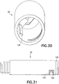
Figures 30 and 31 are perspective views of a body of the medical injector ofFigure 28 ; -
Figures 32 and 33 are perspective views of a rotary knob of the medical injector ofFigure 28 ; and -
Figure 34 is a partial cross-sectional view of a limiter rib for preventing dose setting beyond an available amount. - Reference will now be made in detail to embodiments of the present invention, examples of which are illustrated in the accompanying drawings, wherein like reference numerals refer to the like elements throughout. The embodiments described herein exemplify, but do not limit, the present invention by referring to the drawings. As will be understood by one skilled in the art, terms such as up, down, bottom, and top are relative, and are employed to aid illustration, but are not limiting.
- With reference to the figures, a
medical injector 10 is shown having aratchetable plunger 12 provided therewith. As will be appreciated by those skilled in the art, themedical injector 10 may be of various forms, including being a syringe or pen injector. In accordance with an embodiment of the present invention, themedical injector 10 is particularly well-suited for administering at least one fixed dose, and is even better suited for administering a series of fixed doses. Themedical injector 10 may be configured in any way known to be compatible with theplunger 12 as described herein. Themedical injector 10 may include areservoir 14 for accommodating an injectable medicament, which may be a drug cartridge, or which may be formed directly in themedical injector 10. Thereservoir 14 may have one ormore stoppers 16 associated therewith as known in the art. Themedical injector 10 may also be provided with aneedle 18 for injection which may be removably attached or affixed to themedical injector 10 such as in a "staked" arrangement. - The
plunger 12 is elongated and generally flat. A plurality of spaced-apart ratchetteeth 20 are disposed along the length of theplunger 12. In a preferred arrangement, theplunger 12 includes a plate-shapedbody 22 having opposing first and second faces 24, 26. Theratchet teeth 20 are disposed on thefirst face 24 and, in a further preferred arrangement, also on thesecond face 26. Preferably, theratchet teeth 20 on the first and second faces 24, 26 are axially aligned along the length of theplunger 12. - The
ratchet teeth 20 are configured to permit unidirectional movement of theplunger 12. Particularly, with reference toFigure 3 , theratchet teeth 20 are preferably saw-tooth shaped having a rampedsurface 28 and ashoulder stop 30. As shown inFigure 3 , the ramped surfaces 28 of theratchet teeth 20 on both the first andsecond surfaces - The
plunger 12 may also have one ormore rails 27 extending from thefirst face 24 and/or thesecond face 26. Therails 27 may be formed to slide through one or more corresponding shape-mating slots formed in themedical injector 10. Therails 27 may provide stability during use, particularly during translation of theplunger 12. - With reference to
Figures 4-6 , theplunger 12 is disposed in abody 32 of themedical injector 10. Thebody 32 includes adistal end 34, located to be directed toward a patient during an injection, and aproximal end 36, located to be away from a patient during an injection (Figure 1 ). During use, themedical injector 10 is configured to permit theplunger 12 to move unidirectionally therein in a distal direction toward thedistal end 34, but not in a proximal direction toward theproximal end 36. To facilitate such unidirectional movement, at least oneindexer 38 is provided formed to engage theplunger 12. Theindexer 38 is configured to allow theplunger 12 to displace distally toward thedistal end 34 of thebody 32 but not proximally toward theproximal end 36 of thebody 32. - The
indexer 38 includes adeflectable pawl 40 which, as shown schematically inFigure 3 , includes a rampedengagement surface 42 and an outward facingstop surface 44. Theindexer 38 is outwardly deflectable to permit theengagement surface 42 to ascend the rampedsurface 28 of an individual of theratchet teeth 20 with theplunger 12 moving distally relative thereto. With sufficient distal movement, theindexer 38 bypasses theratchet teeth 12, and under inherent resilience of theindexer 38, snaps inwardly such that thestop surface 44 is aligned with theshoulder stop 30. Preferably, thestop surface 44 is formed to be generally parallel to theshoulder stop 30. With rearward (proximal) movement of theplunger 12, theshoulder stop 30 and thestop surface 44 interferingly engage thus preventing proximal movement of theplunger 12. In a preferred embodiment, a pair of theindexers 38 are provided so as to act against theratchet teeth 20 located on both the first and second faces 24, 26, as shown inFigures 4-6 . It is further preferred that a pair of theindexers 38 be provided which are axially aligned thus providing a pinching effect to theplunger 12. This pinching effect may provide a stable holding force for theplunger 12. - The
indexer 38 may be formed to be deflectable through inherent resilience, such as through material selection (e.g., being formed of a thermoplastic). In addition, or alternatively, theindexer 38 may include acantilevered arm 46 which permits deflection of the associatedpawl 40. Theindexer 38 is formed to have a natural, unbiased state as shown inFigures 4-6 , where theindexer 38 is positioned to act against theshoulder stop 30 of theratchet teeth 20. The cantileveredarm 46 is formed with sufficient internal memory to provide the unbiased state for theindexer 38. - The
medical injector 10 also includes anactuator 48 having anengagement portion 50 formed to engage one or more of theratchet teeth 20. Theengagement portion 50 preferably includes anengagement pawl 52 having a rampedengagement surface 54 and an outward facingstop surface 56 configured like thepawl 40 described above. Preferably, two of theengagement portions 50 are provided located to engage theratchet teeth 20 located on the first and second faces 24, 26. - With reference to
Figure 4 , theplunger 12 is positioned to engage one of thestoppers 16. To cause actuation of themedical injector 10, as shown inFigure 5 , theactuator 48 is moved to a ready state, with theengagement portion 50 moving proximally. Theindexer 38 prevents proximal movement of theplunger 12, thus allowing theactuator 48 to move proximally relative to theplunger 12. With theplunger 12 being held stationary, and theengagement portion 50 moving proximally relative to theplunger 12, theengagement portion 50 bypasses one or more of theratchet teeth 20. Theactuator 48 is displaced sufficiently to achieve a ready state. - For actuation of the
medical injector 10, theactuator 48 is displaced from the ready state with distal movement of theengagement portion 50. Theengagement portion 50 engages one or more of theratchet teeth 20, particularly with interfering engagement between theshoulder stop 30 and thestop surface 56. In particular, theengagement portion 50 engages the nextdistal ratchet tooth 20. Distal movement of theengagement portion 50 causes theplunger 12 to move distally therewith. Distal movement of theplunger 12, in turn, causes distal advancement of thestopper 16 in causing an injection to be administered. Theratchet teeth 20 are able to bypass theindexer 38 in the distal direction. - The size of a dose to be administered by the
medical injector 10 is a function of the spacing between theratchet teeth 20 and/or the amount of proximal displacement of theengagement portion 50 relative to theratchet teeth 20 with theactuator 48 moving to a ready state. To create a fixed dose, one ormore keys 58 may be defined on themedical injector 10 and/or theactuator 48 which are formed to nest within and slide alongcorresponding channels 60 formed in themedical injector 10 and/or theactuator 48. As shown inFigures 4-6 , it is preferred that thekeys 58 be formed on theactuator 48 and thechannels 60 be formed in themedical injector 10. With reference toFigure 4 , thekeys 58 are at the distal end of thechannel 60, prior to use. With proximal displacement of theactuator 48, thekeys 58 are proximally advanced in thechannels 60 to a proximal-most position corresponding to the ready state of theactuator 48. The length of the travel of thekeys 58 in thechannels 60 restricts the range of movement of theactuator 48 in defining the size of the dose administrable by themedical injector 10. As shown inFigures 5 and 6 , thekeys 58 are advanced distally with theactuator 48 during use to a distal-most position. - The
actuator 48 shown inFigures 4-6 is a linear slide actuator which applies force directly to theplunger 12. As will be appreciated by those skilled in the art, theactuator 48 may be of various configurations. With reference toFigures 7-8 , theactuator 48 may include arocker 62 pivotally mounted thereto. Therocker 62 is frame-shaped, having afirst end 64 for pivotal mounting to theactuator 48 and a second opposingend 66 for pivotally mounting to themedical injector 10. Theengagement portion 50 is located between the first and second ends 64, 66. As shown inFigures 7 and 8 , two of theengagement portions 50 may be provided to coact with theratchet teeth 20 being located on the first and second faces 24, 26. - It is noted that the spacing between the first and second ends 64, 66 affects force transmission from the
actuator 48 to theplunger 12 particularly in the generation of torque. The spacing L between the first and second ends 64, 66, as well as the spacing SI, S2 of theengagement portion 50 from the first and second ends 64, 66, affects how torque is generated and transmitted to theplunger 12. - With reference to
Figure 9 , theactuator 48 is shown in an initial pre-use state with therocker 62 being inclined distally. With reference toFigure 10 , theactuator 48 has been advanced to the ready state with therocker 62 having been drawn proximally with rotation about thesecond end 66 so as to be inclined in a proximal direction. During this movement, theengagement portion 50 bypasses one or more of theratchet teeth 20 in the same manner as described above. As shown inFigure 11 , theactuator 48 is displaced from the ready state to cause actuation of themedical injector 10. With displacement of the actuator 48 from the ready state, therocker 62 is caused to advance distally about thesecond end 66 with theengagement portion 50 causing theplunger 12 to also advance distally. Dose size may be restricted both by the key 58/channel 60 arrangement described above and/or by the range of motion of therocker 62. - As will be appreciated by those skilled in the art, the
rocker 62 may be directly coupled to theactuator 48, as shown inFigures 9-11 . As will be appreciated by those skilled in the art, a multi-link arrangement may be used to couple therocker 62 to theactuator 48. With reference toFigures 12 and 13 , one ormore links 68 may be connected between therocker 62 and theactuator 48 to provide force for displacement thereof. Any arrangement of thelinks 68 may be utilized which transmits force from theactuator 48 to therocker 62. As shown inFigures 12 and 13 , two of the links 68 (68A, 68B) are utilized with the link 68Abeing pivotally connected to theactuator 48 and pivotally connected to thelink 68B, and with thelink 68B being pivotally connected to thelink 68A and pivotally connected to therocker 62. Thelinks rocker 62. - With reference to
Figures 15-17 , theactuator 48 may be arranged to be non-linearly displaced. As shown inFigures 15-17 , theactuator 48 may be formed to pivot about afulcrum 70. With theactuator 48 pivoting outwardly from themedical injector 10 about thefulcrum 70, theengagement portion 50 is caused to be displaced proximally. Conversely, inward pivoting of theactuator 48 about the fulcrum 70 causes distal displacement of theengagement portion 50. Theengagement portion 50 coacts with theplunger 12 in the same manner as described above. - With reference to
Figures 15 and16 , themedical injector 10 is shown in a pre-use state. To facilitate handling of theactuator 48, a grip ring orpad 72 may be provided which extends radially outwardly from themedical injector 10 to facilitate displacement of theactuator 48. To prepare for use, as shown by the arrow inFigure 16 , theactuator 48 is pivoted to a ready state as shown inFigure 17 . To cause actuation of themedical injector 10, theactuator 48 is pivoted inwardly from the ready state, as shown by the arrow inFigure 17 . - The size of the dose may be fixed with the
actuator 48 being pivotable by limiting the range of rotation of theactuator 48.Aportion 74 of themedical injector 10 may be configured to limit the range of rotation of theactuator 48, particularly outward rotation, such limited range corresponding to the ready state. - The
actuator 48 may be formed as a linear slide actuator, but configured to accept a non-linear force to adjust theactuator 48 to the ready state. With reference toFigures 18-27 , theactuator 48 may include afirst portion 48A, formed in accordance with the description above. In addition, theactuator 48 may include a rotatablesecond portion 48B coupled to thefirst portion 48A so as to be rotatable relative thereto. This arrangement permits rotational adjustment of theactuator 48 to the ready state. Rotational adjustment is typical of pen-type injectors and may be preferred by some users. - The
second portion 48B is accessible exteriorly of themedical injector 10 so as to be engageable from the outside by a user; particularly, thesecond portion 48B extends proximally from theproximal end 36 of thebody 32. The first andsecond portions second portion 48B may be formed with acontinuous ring 80 seated inchannel 82 of thefirst portion 48A. Thering 80 is sized and shaped to rotate freely within thechannel 82 with the first andsecond portions ring 80 and thechannel 82 may be reversed on the first andsecond portions - As shown in
Figure 19 , agroove 84 is formed about an exterior of thesecond portion 48B. One ormore keys 86 are located on surrounding portions of themedical injector 10, e.g., on thebody 32, about thesecond portion 48B positioned and sized to be seated in thegroove 84 so as to be moveable along the length thereof. The length of thegroove 84 delimits the extent of rotation of thesecond portion 48B. According to one embodiment, thegroove 84 is at least partially helical so as to have a screw thread shape. As will be appreciated by those skilled in the art, the key(s) 86 may be located on the exterior of thesecond portion 48B and the correspondinggroove 84 may be formed on surrounding portions of themedical injector 10. - Rotation of the
second portion 48B in a first rotational direction results in proximal displacement of the first andsecond portions engagement portion 50 to the ready state. In particular, rotation of thesecond portion 48B results in proximal displacement thereof and, in concert, proximal displacement of thefirst portion 48A and of theengagement portion 50. Thefirst portion 48A is non-rotatably displaced proximally. The length of thegroove 84 limits the extent of rotation of thesecond portion 48B thereby limiting the dose that may be administered. Once rotated to a set dose, the dose may be administered by pressing thesecond portion 48B, which results in distal advancement of thesecond portion 48B and, correspondingly, distal non-rotating advancement of thefirst portion 48 along with theengagement portion 50. - With distal advancement of the
second portion 48B, it is preferred that thesecond portion 48B be advanced linearly without rotation. To this end, it is preferred that thegroove 84 be formed with a firsthelical portion 84a and a secondaxial portion 84b extending from the firsthelical portion 84a generally parallel to the longitudinal axis of thesecond portion 48B. Referring toFigure 21 , with this arrangement, the one ormore keys 86 traverse the firsthelical portion 84a with rotation of thesecond portion 48B in a proximal direction.Elbow 88 is defined at the junction of the firsthelical portion 84a and the secondaxial portion 84b which limits the extent of rotation and, thus, proximal displacement of thesecond portion 48B. Theelbow 88 defines the ready position of theactuator 48. For actuation, thesecond portion 48B is depressed and caused to advance distally linearly without rotation with the one ormore keys 86 traversing the secondaxial portion 84b. This, in turn, causes distal advancement of thefirst portion 48A and distal advancement of theplunger 12 through engagement with theengagement portion 50. The linear displacement of thesecond portion 48B permits force applied thereto to be fully transmitted in one axial direction, without resolution into two or more components. As such, the full force of actuation applied to thesecond portion 48B is transmitted to theactuator 48. - For a single-dose version of this arrangement, a single set of the first helical portion and the second
axial portion Figure 22 , thegroove 84 may be extended such that a secondaryhelical portion 84a' may extend directly from the terminus of the secondaxial portion 84b which extends into a secondaryaxial portion 84b' and so forth as needed. According to one embodiment, a series of the firsthelical portions 84a and secondaxial portions 84b may be defined continuously about thesecond portion 48B to facilitate multiple dosing. According to one embodiment more than onegroove 84 may be utilized with a corresponding set of one ormore keys 86. Also, one or more of thegrooves 84 and one or more of thekeys 86 may be located on thesecond portion 48B and/or surrounding portions of themedical injector 10. - Preferably, reverse rotation of the
second portion 48B should be avoided. To this end, as shown inFigures 23-24 , one ormore detents 90 may be formed on thesecond portion 48B formed to snap engage one ormore locating channels 92 formed on themedical injector 10 about thesecond portion 48B, such as on thebody 32. Preferably, a locatingchannel 92 is located corresponding to thesecond portion 48B being in the ready position, and such a readyposition locating channel 92 is elongated such that thedetent 90 may be displaced along the length thereof with thesecond portion 48B during dose administration. As will be appreciated by the skilled in the art, the detent(s) 90 may be formed on themedical injector 10 and the locating channels may be formed on thesecond portion 48B. - In addition, reverse axial movement along the second
axial portion 84b, particularly after injection, is undesired. To this end, as shown inFigures 25 and 26 , alocking tab 94 is provided on thesecond portion 48B which is configured to snap engage into a lockingchannel 96 at a position coinciding with an end of the injection (e.g., position coinciding with the one ormore keys 86 reaching the terminus of the secondaxial portion 84b at the end of a dosing stroke). Axial movement of thesecond portion 48B is thus limited. The lockingchannel 96 may be configured to permit rotation of thelocking tab 94 for separation therefrom with rotation of thesecond portion 48B in preparing for a subsequent dose. The locking channel 96is formed on a surrounding portion of themedical injector 10, such as on thebody 32. As will be appreciated by those skilled in the art, thelocking tab 94 may be formed on themedical injector 10 and the lockingchannel 96 may be provided on thesecond portion 48B. - Further, as will be appreciated by those skilled in the art, with the arrangement discussed above, particularly with the use of the first and
second portions groove 84, doses are fixed doses. According to one embodiment to allow for variable dosing, thesecond portion 48B may be allowed to rotate during distal advancement of thesecond portion 48B with the one ormore keys 86 traveling along thegroove 84. Thus, in this embodiment, as shown inFigure 27 , only thehelical portion 84a of thegroove 84 need be provided. With this arrangement, thesecond portion 48B may be rotated to any location along the groove 84 (84a) to set a dose with reverse rotation along the groove 84 (84a) permitting dosing. A scale, or other index, as known in the art may be provided to correspond to rotational displacement of thesecond portion 48B to provide indication of the set dose amount. To limit unwanted reverse rotation, and to retain position at a set dose, a releasable retention arrangement, as is in known in the art, may be utilized. - The first and
second portions second portions rocker 62. -
Figure 28 is a perspective view of themedical injector 10 in accordance with another embodiment of the present invention. With reference toFigures 28-33 ,medical injector 10 includes abody 32, arotary knob 100 rotatably connected to thebody 32, anactuator 48 disposed within thebody 32, and acap 101 connected to theactuator 48. As shown inFigure 29 , theactuator 48 includes thegroove 84 as described above. Theactuator 48 also includes anaxial groove 102. Theaxial groove 102 interacts with an axial key 104 (shown inFigure 30 ) disposed on an interior of thebody 32 to guide axial movement of theactuator 48 with respect to thebody 32 and prevent rotation of theactuator 48 with respect to thebody 32. As will be appreciated by those skilled in the art, theaxial groove 102 may be disposed on the interior of thebody 32 and theaxial key 104 may be disposed on theactuator 48, without departing from the scope of the invention. - As shown in
Figure 31 , thebody 32 also includes acircumferential groove 106 disposed at a proximal end thereof for connection with therotary knob 100, as will be described in greater detail below. Additionally, as will be described in greater detail below, thebody 32 includes a cantilevered,circumferential arm 120 with atriangular protrusion 122 disposed at an end thereof and protruding radially outward. -
Figure 32 is a perspective view of the distal end of therotary knob 100 andFigure 33 is a perspective view of the proximal end of therotary knob 100. As shown inFigure 32 , therotary knob 100 includes a circumferentially extending and radially inward protrudingconnector 108. According to one embodiment, theconnector 108 is substantially wedge-shaped. To assemble themedical injector 10, therotary knob 100 is distally inserted over the proximal end of thebody 32 until theconnector 108 slips into thecircumferential groove 106 of thebody 32, connecting therotary knob 100 to thebody 32. The wedge shape of theconnector 108 secures therotary knob 100 to thebody 32, substantially preventing proximal displacement of therotary knob 100 relative to thebody 32 while permitting rotation of therotary knob 100 relative to thebody 32. - As shown in
Figure 32 , theconnector 108 is disposed in alarge diameter portion 110 of therotary knob 100. Also disposed in thelarge diameter portion 110 of therotary knob 100 is atriangular groove 112. Thetriangular groove 112 interacts with thetriangular protrusion 122 on thearm 120 to permit unidirectional rotation of therotary knob 100 with respect to thebody 32. That is, thetriangular groove 112 and thetriangular protrusion 122 interact to permit rotation of therotary knob 100 only in a direction to advance theplunger 12 proximally. Therotary knob 100 also has a reduceddiameter portion 114 which prevents proximal displacement of the rotary knob relative to the body subsequent to connection between theconnector 108 and thecircumferential groove 106. Additionally, a camming projection or key 116 projects radially inward from the reduceddiameter portion 114. Similar to the key 86 described above, the key 116 interacts with thegroove 84 of theactuator 48 to convert rotational movement of therotary knob 100 into proximal axial movement of theactuator 48. Subsequent to the proximal axial movement of theactuator 48, the user depresses the cap 101 (connected to the actuator 48) to distally displace theactuator 48 relative to thebody 32, and thus distally advance theplunger 12. - Referring to
Figure 33 , therotary knob 100 also includes radially outward projectingribs 118 at a proximal end thereof. Theribs 118 function as a user interface for the user to grasp and rotate therotary knob 100. - As will be appreciated by those skilled in the art, the
medical injector 10 may be utilized with various features. With reference toFigures 12-14 , a dose counter may be provided with themedical injector 10 which gives an indication of the number of available doses to be administered. For example, a series ofdose indicating holes 76 may be formed in themedical injector 10, particularly to be visible from the outside thereof. Apointer 78 may be provided on theactuator 48 and formed to be visible through a single one of thedose indicating holes 76 in a given instance. During use, with theplunger 12 being distally advanced dose by dose, thepointer 78 is likewise advanced along the series of the dose indicating holes 76. According to one embodiment, the number of thedose indicating holes 76 located distally of thepointer 78 provides as an indication of the remaining number of doses. With thepointer 78 appearing in the distal-most of thedose indicating holes 76, indication is provided that no remaining doses are available for administration. - It is preferred that the
pointer 78 be formed of a contrasting color relative to the portion of themedical injector 10 located about thedose indicating holes 76, so that thepointer 78 is readily visible through the dose indicating holes 76. - In addition, according to one embodiment shown in
Figure 34 , a protrudinglimiter rib 98 may extend from a distal portion of theplunger 12 located to coincide with the dosage setting on theplunger 12 corresponding to the last amount of available drug in thereservoir 14. Accordingly, with a predetermined extent of distal advancement of theplunger 12, thelimiter rib 98 is formed to interferingly engage a portion of theactuator 48 and block proximal movement therepast. In this manner, a dose greater than the available amount in thereservoir 14 cannot be set by theactuator 48. - Although only a few embodiments of the present invention have been shown and described, the present invention is not limited to the described embodiments. Instead, it will be appreciated by those skilled in the art that changes may be made to these embodiments without departing from the principles and spirit of the invention, the scope of which is defined by the claims and their equivalents.
- Further Aspects:
- 1. A medical injector, comprising:
- a body having a distal end and a proximal end;
- a plunger displaceably disposed in the body, the plunger having a plurality of spaced-apart ratchet teeth disposed along the length thereof, the plunger selectively displacing a stopper to dispense a medicament from said medical injector;
- an indexer disposed within the body to engage the plunger to permit distal displacement of the plunger and substantially prevent proximal displacement of the plunger;
- an actuator having an engagement portion to engage the plunger to permit proximal displacement of the actuator relative to the plunger and substantially prevent distal displacement of the actuator relative to the plunger; and
- a rotating member for proximally displacing the engagement portion relative to the plunger and the body;
- wherein upon proximal displacement of the actuator relative to the body to a ready state, one or more of the ratchet teeth bypass the engagement portion to proximally displace the actuator relative to the plunger; and
- wherein upon distal displacement of the actuator relative to the body from the ready state, the actuator engages one or more of the ratchet teeth to distally displace the plunger relative to the indexer to distally displace the stopper to dispense medicament from the medical injector.
- 2. The medical injector according to further aspect 1, wherein at least a portion of the actuator is slidably displaceable relative to the body.
- 3. The medical injector according to further aspect 1, further comprising a rocker for determining force transmission from the actuator to the plunger and/or for defining a dosage amount, the rocker being pivotably connected to the actuator and pivotably connected to the body.
- 4. The medical injector according to further aspect 1, further comprising:
- a rocker for determining force transmission from the actuator to the plunger and/or for defining a dosage amount, the rocker being pivotably connected to the actuator;
- a first link pivotably connected to the actuator; and
- a second link disposed between the rocker and the first link and pivotably connected to the rocker and the first link.
- 5. The medical injector according to further aspect 1, wherein at least one key extends from one of the actuator and the body, and a channel is provided in the remaining one of the actuator and the body, the key being configured to be slidably received in the channel for defining a dosage amount.
- 6. The medical injector according to further aspect 1, wherein the actuator comprises:
- a first actuator portion on which the engagement portion is disposed; and
- the rotating member, the rotating member comprising a second actuator portion rotatably coupled to the first actuator portion;
- wherein the second actuator portion is rotatably displaceable to the ready state, thereby proximally displacing the first actuator portion relative to the body, and upon rotatable displacement of the second actuator portion to the ready state, one or more of the ratchet teeth bypass the engagement portion to proximally displace the first and second actuator portions relative to the plunger; and
- wherein the second actuator portion is distally displaceable from the ready state relative to the body, thereby distally and non-rotatably displacing the first actuator, and upon the distal displacement of the second actuator portion from the ready state, the engagement portion engages one or more of the ratchet teeth and to distally displace the plunger to distally displace the stopper to dispense medicament from the medical injector.
- 7. The medical injector according to further aspect 6, wherein:
- one of the second actuator portion and the body has a groove and the remaining one of the second actuator portion and the body has a corresponding key slidably received in the groove; and
- movement of the key relative to the groove causes displacement of the second actuator part.
- 8. The medical injector according to
further aspect 7, wherein the groove comprises a substantially helical portion, and movement of the key relative to the helical portion induces rotation of the second actuator part. - 9. The medical injector according to further aspect 8, further comprising an index visible to a user for setting a desired dosage as the key moves in the helical portion.
- 10. The medical injector according to further aspect 8, wherein the groove further comprises an axial portion, and movement of the key relative to the axial portion causes axial displacement of the second actuator part for distally displacing the actuator from the ready state.
- 11. The medical injector according to
further aspect 10, wherein the groove comprises a plurality of helical portions contiguously connected by a corresponding plurality of axial portions. - 12. The medical injector according to further aspect 6, wherein one of the second actuator portion and the body has a locating channel and the remaining one of the second actuator portion and the body has a corresponding detent to snap engage the locating channel, to permit rotation of the second actuator portion in a first direction and prevent reverse rotation of the second actuator.
- 13. The medical injector according to
further aspect 10, wherein:- one of the second actuator portion and the body has a locating channel and the remaining one of the second actuator portion and the body has a corresponding detent to snap engage the locating channel, to permit rotation of the second actuator portion in a first direction and to engage the detent and prevent reverse rotation of the second actuator portion; and
- the locating channel is axially elongated, to permit axial displacement of the second actuator portion.
- 14. The medical injector according to
further aspect 10, wherein one of the second actuator portion and the body has a locking channel and the remaining one of the second actuator portion and the body has a corresponding locking tab to snap engage the locking channel at a position corresponding with an end of a dispensed dosage from the medical injector, to prevent non-rotating proximal movement of the second actuator portion. - 15. The medical injector according to further aspect 1, wherein the rotating member comprises a rotary knob rotatably disposed at a proximal end of the body;
wherein one of the actuator and an interior of the body comprises an axial groove and the remaining one of the actuator and the interior of the body comprises a corresponding axial key slidably received in the axial groove to guide axial displacement of the actuator relative to the body and prevent rotation of the actuator relative to the body;
wherein one of the actuator and the rotary knob comprises a groove with a substantially helical portion and the remaining one of the actuator and the rotary knob comprises a corresponding key slidably received in the groove; and
wherein rotation of the rotary knob induces displacement of the key relative to the groove, thereby axially displacing the actuator relative to the body. - 16. The medical injector according to further aspect 15, wherein one of the rotary knob and the body comprises a connector and the remaining one of the rotary knob and the connector comprises a corresponding circumferential groove rotatably receiving the connector for rotatably connecting the rotary knob to the proximal end of the body.
- 17. The medical injector according to further aspect 15, wherein the rotary knob comprises a shaped axial groove and the body comprises a cantilevered arm having a shaped protrusion radially protruding from an end of the cantilevered arm, the shaped protrusion having a shape corresponding to the shape of the shaped axial groove; and
wherein the shaped axial groove engages the protrusion to permit unidirectional rotation of the rotary knob relative to the body. - 18. The medical injector according to further aspect 15, wherein the shape of the shaped axial groove and the corresponding shaped protrusion is substantially triangular.
- 19. A medical injector, comprising:
- a body having a distal end and a proximal end;
- a plunger displaceably disposed in the body, the plunger having a plurality of spaced-apart ratchet teeth disposed along the length thereof, the plunger selectively displacing a stopper to dispense a medicament from said medical injector;
- an indexer disposed within the body to engage the plunger to permit distal displacement of the plunger and substantially prevent proximal displacement of the plunger;
- actuating means for actuating the medical device, the actuating means having engagement means for engaging the plunger to permit proximal displacement of the actuating means relative to the plunger and substantially prevent distal displacement of the actuating means relative to the plunger; and
- rotating means for proximally displacing the engagement means relative to the plunger and the body;
- wherein upon proximal displacement of the actuating means relative to the body to a ready state, one or more of the ratchet teeth bypass the engagement means to proximally displace the actuating means relative to the plunger; and
- wherein upon distal displacement of the actuating means relative to the body from the ready state, the actuating means engages one or more of the ratchet teeth to distally displace the plunger relative to the indexer to distally displace the stopper to dispense medicament from the medical injector.
- 20. A method of injecting a medicament from a medical injector having a body with distal and proximate ends, the method comprising:
- permitting distal displacement of a plunger with respect to the body and substantially preventing proximal displacement of the plunger with respect to the body;
- permitting proximal displacement of an actuator relative to the plunger and substantially preventing distal displacement of the actuator relative to the plunger;
- rotating a rotating member to proximally displace the actuator relative to the body to a ready state, thereby proximally displacing the actuator relative to the plunger; and distally displacing the actuator relative to the body from the ready state, thereby engaging the plunger and distally displacing the plunger relative to the body to dispense medicament from the medical injector.
Claims (12)
- A medical injector(10), comprising:a body (32) having a distal end and a proximal end;a plunger (12) displaceably disposed in the body, the plunger having a plurality of spaced-apart ratchet teeth (20) disposed along the length thereof, the plunger selectively displacing a stopper (16) to dispense a medicament from said medical injector;an indexer (38) disposed within the body to engage the plunger to permit distal displacement of the plunger and substantially prevent proximal displacement of the plunger; andan actuator (48) comprising:a first actuator portion (48A) having an engagement portion (50) to engage the plunger to permit proximal displacement of the actuator relative to the plunger and substantiallyprevent distal displacement of the actuator relative to the plunger; anda second actuator portion (48B) rotatably coupled to the first actuator portion to be rotatable relative thereto, the second actuator being configured to, upon rotation of the second actuator portion relative to the body to a ready state, proximally displace the second actuator portion relative to the body in concert with non-rotatable proximal displacement of the first actuator portion and the engagement portion 50 relative to the plunger.
- The medical injector according to claim 1, wherein one of the first and second actuator portions (48A, 48B comprises a ring (80) and the remaining one of the first and second actuator portions comprises a channel (82), the ring being seated in the channel and being sized and shaped to rotate freely therein to rotatably couple the first and second actuator portions.
- The medical injector according to any of the previous claims, wherein one of the second actuator portion and the body comprises a groove (84) and the remaining one of the second actuator portion and the body comprises a key (86) configured to be seated in the groove to be movable along the groove.
- The medical injector according to claim 3, wherein:
the second actuator portion is configured to be distally displaceable from the ready state relative to the body, thereby distally and non-rotatably displacing the first actuator portion, and upon the distal displacement of the second actuator portion from the ready state, the engagement portion is configured to engage one or more of the ratchet teeth and to distally displace the plunger to distally displace the stopper to dispense medicament from the medical injector. - The medical injector according to claim 3, wherein the groove comprises a substantially helical portion (84A), and movement of the key relative to the helical portion induces rotation of the second actuator portion.
- The medical injector according to claim 5, further comprising an index visible to a user for setting a desired dosage as the key moves in the helical portion.
- The medical injector according to claim 5, wherein the groove further comprises an axial portion (84B), and movement of the key relative to the axial portion causes axial displacement of the second actuator portion for distally displacing the actuator from the ready state.
- The medical injector according to claim 7, wherein the groove comprises a plurality of helical portions (84A) contiguously connected by a corresponding plurality of axial portions (84B).
- The medical injector according to claim 1, wherein one of the second actuator portion and the body has a locating channel (92) and the remaining one of the second actuator portion and the body has a corresponding detent (90) to snap engage the locating channel, to permit rotation of the second actuator portion in a first direction and prevent reverse rotation of the second actuator.
- The medical injector according to claim 7, wherein:one of the second actuator portion and the body has a locating channel (92) and the remaining one of the second actuator portion and the body has a corresponding detent (90) to snap engage the locating channel, to permit rotation of the second actuator portion in a first direction and to engage the detent and prevent reverse rotation of the second actuator portion; andthe locating channel is axially elongated, to permit axial displacement of the second actuator portion.
- The medical injector according to claim 7, wherein one of the second actuator portion and the body has a locking channel (96) and the remaining one of the second actuator portion and the body has a corresponding locking tab (94) to snap engage the locking channel at a position corresponding with an end of a dispensed dosage from the medical injector, to prevent non rotating proximal movement of the second actuator portion.
- The medical injector according to claim 1, further comprising a protruding limiter rib (98) extending from the plunger 12, wherein the protruding limiter rib is configured to interferingly engage a portion of the actuator 48 and block proximal movement therepast so that a dose greater than the available amount in the reservoir cannot be set by the actuator.
Priority Applications (3)
| Application Number | Priority Date | Filing Date | Title |
|---|---|---|---|
| DK18169323.5T DK3375468T3 (en) | 2011-03-17 | 2011-03-17 | Medical injector with ratchet acting piston |
| EP18169323.5A EP3375468B1 (en) | 2011-03-17 | 2011-03-17 | Medical injector with ratcheting plunger |
| ES18169323T ES2771578T3 (en) | 2011-03-17 | 2011-03-17 | Ratchet Plunger Medical Injector |
Applications Claiming Priority (3)
| Application Number | Priority Date | Filing Date | Title |
|---|---|---|---|
| EP11860740.7A EP2686034B1 (en) | 2011-03-17 | 2011-03-17 | Medical injector with ratcheting plunger |
| EP18169323.5A EP3375468B1 (en) | 2011-03-17 | 2011-03-17 | Medical injector with ratcheting plunger |
| PCT/US2011/000493 WO2012125133A1 (en) | 2011-03-17 | 2011-03-17 | Medical injector with ratcheting plunger |
Related Parent Applications (1)
| Application Number | Title | Priority Date | Filing Date |
|---|---|---|---|
| EP11860740.7A Division EP2686034B1 (en) | 2011-03-17 | 2011-03-17 | Medical injector with ratcheting plunger |
Publications (2)
| Publication Number | Publication Date |
|---|---|
| EP3375468A1 true EP3375468A1 (en) | 2018-09-19 |
| EP3375468B1 EP3375468B1 (en) | 2019-11-20 |
Family
ID=46831001
Family Applications (3)
| Application Number | Title | Priority Date | Filing Date |
|---|---|---|---|
| EP18169323.5A Active EP3375468B1 (en) | 2011-03-17 | 2011-03-17 | Medical injector with ratcheting plunger |
| EP18169309.4A Withdrawn EP3375467A1 (en) | 2011-03-17 | 2011-03-17 | Medical injector with ratcheting plunger |
| EP11860740.7A Active EP2686034B1 (en) | 2011-03-17 | 2011-03-17 | Medical injector with ratcheting plunger |
Family Applications After (2)
| Application Number | Title | Priority Date | Filing Date |
|---|---|---|---|
| EP18169309.4A Withdrawn EP3375467A1 (en) | 2011-03-17 | 2011-03-17 | Medical injector with ratcheting plunger |
| EP11860740.7A Active EP2686034B1 (en) | 2011-03-17 | 2011-03-17 | Medical injector with ratcheting plunger |
Country Status (6)
| Country | Link |
|---|---|
| EP (3) | EP3375468B1 (en) |
| JP (1) | JP5823542B2 (en) |
| CN (1) | CN103501835B (en) |
| DK (2) | DK3375468T3 (en) |
| ES (2) | ES2771578T3 (en) |
| WO (1) | WO2012125133A1 (en) |
Families Citing this family (5)
| Publication number | Priority date | Publication date | Assignee | Title |
|---|---|---|---|---|
| JP5657541B2 (en) | 2008-09-18 | 2015-01-21 | ベクトン・ディキンソン・アンド・カンパニーBecton, Dickinson And Company | Medical injector with a ratchet driven plunger |
| CN105641782B (en) * | 2011-03-17 | 2019-06-14 | 贝克顿·迪金森公司 | Medical injector with ratchet-type plunger |
| DK3104909T3 (en) | 2014-02-14 | 2019-10-28 | Shl Medical Ag | AUTOMATIC INJECTION DEVICE |
| EP3389742B1 (en) * | 2015-12-18 | 2024-01-24 | Merck Sharp & Dohme LLC | Metering injector for delivering liquid, and method of using same |
| SG10201805432QA (en) * | 2018-06-25 | 2020-01-30 | Racer Tech Pte Ltd | Dosage Specific Formula Dispensing Pen |
Citations (5)
| Publication number | Priority date | Publication date | Assignee | Title |
|---|---|---|---|---|
| US20020016571A1 (en) * | 1999-01-12 | 2002-02-07 | Fritz Kirchhofer | Device for administering an injectable product |
| US20050154351A1 (en) * | 2002-07-17 | 2005-07-14 | Roney Graf | Administration device comprising a priming function |
| US20070106227A1 (en) * | 2004-04-23 | 2007-05-10 | Stefan Burren | Device for Administering an Injectable Product with a Lockable Dose Metering Mechanism |
| WO2009121194A1 (en) * | 2008-04-01 | 2009-10-08 | Tecpharma Licensing Ag | Device for administering a fluid product |
| US20100094206A1 (en) * | 2006-11-17 | 2010-04-15 | Sanofi-Aventis Deutschland Gmbh | Drive mechanisms suitable for use in drug delivery devices |
Family Cites Families (5)
| Publication number | Priority date | Publication date | Assignee | Title |
|---|---|---|---|---|
| DE4425763A1 (en) * | 1994-07-21 | 1996-01-25 | Braun Medical Ag | Device for advancing a piston displacement member |
| AU777369B2 (en) * | 1999-04-16 | 2004-10-14 | Becton Dickinson & Company | Pen style injector with automated substance combining feature |
| EP2258424B1 (en) * | 2001-05-16 | 2013-01-30 | Eli Lilly and Company | Medication injector apparatus |
| DE102007032463A1 (en) * | 2007-07-10 | 2009-01-15 | Lts Lohmann Therapie-Systeme Ag | Disposable injector with at least one positively decoupling towing hook |
| JP5657541B2 (en) * | 2008-09-18 | 2015-01-21 | ベクトン・ディキンソン・アンド・カンパニーBecton, Dickinson And Company | Medical injector with a ratchet driven plunger |
-
2011
- 2011-03-17 EP EP18169323.5A patent/EP3375468B1/en active Active
- 2011-03-17 CN CN201180070446.6A patent/CN103501835B/en active Active
- 2011-03-17 EP EP18169309.4A patent/EP3375467A1/en not_active Withdrawn
- 2011-03-17 ES ES18169323T patent/ES2771578T3/en active Active
- 2011-03-17 DK DK18169323.5T patent/DK3375468T3/en active
- 2011-03-17 EP EP11860740.7A patent/EP2686034B1/en active Active
- 2011-03-17 JP JP2013557996A patent/JP5823542B2/en active Active
- 2011-03-17 ES ES11860740.7T patent/ES2682305T3/en active Active
- 2011-03-17 WO PCT/US2011/000493 patent/WO2012125133A1/en unknown
- 2011-03-17 DK DK11860740.7T patent/DK2686034T3/en active
Patent Citations (5)
| Publication number | Priority date | Publication date | Assignee | Title |
|---|---|---|---|---|
| US20020016571A1 (en) * | 1999-01-12 | 2002-02-07 | Fritz Kirchhofer | Device for administering an injectable product |
| US20050154351A1 (en) * | 2002-07-17 | 2005-07-14 | Roney Graf | Administration device comprising a priming function |
| US20070106227A1 (en) * | 2004-04-23 | 2007-05-10 | Stefan Burren | Device for Administering an Injectable Product with a Lockable Dose Metering Mechanism |
| US20100094206A1 (en) * | 2006-11-17 | 2010-04-15 | Sanofi-Aventis Deutschland Gmbh | Drive mechanisms suitable for use in drug delivery devices |
| WO2009121194A1 (en) * | 2008-04-01 | 2009-10-08 | Tecpharma Licensing Ag | Device for administering a fluid product |
Also Published As
| Publication number | Publication date |
|---|---|
| CN103501835B (en) | 2016-08-17 |
| EP2686034A4 (en) | 2014-08-27 |
| JP5823542B2 (en) | 2015-11-25 |
| EP3375467A1 (en) | 2018-09-19 |
| WO2012125133A1 (en) | 2012-09-20 |
| EP3375468B1 (en) | 2019-11-20 |
| CN103501835A (en) | 2014-01-08 |
| JP2014513587A (en) | 2014-06-05 |
| ES2771578T3 (en) | 2020-07-06 |
| DK3375468T3 (en) | 2020-02-24 |
| ES2682305T3 (en) | 2018-09-19 |
| DK2686034T3 (en) | 2018-08-06 |
| EP2686034A1 (en) | 2014-01-22 |
| EP2686034B1 (en) | 2018-05-02 |
Similar Documents
| Publication | Publication Date | Title |
|---|---|---|
| US10143807B2 (en) | Medical injector with ratcheting plunger | |
| EP3251714B1 (en) | Medical injector with rotatable ratcheting plunger | |
| US10980947B2 (en) | Drive and dosing device with a stop element for preventing the setting of a dose | |
| JP2016518232A (en) | Forward-loading drug delivery device with moved cartridge holder and piston rod coupler | |
| EP3375468B1 (en) | Medical injector with ratcheting plunger | |
| JP2007508074A (en) | Injection device for administering a fluid formulation | |
| JP6316945B2 (en) | Drug delivery device having piston rod coupler | |
| JP2016518231A (en) | Forward-loading drug delivery device with dynamic axial stop feature |
Legal Events
| Date | Code | Title | Description |
|---|---|---|---|
| PUAI | Public reference made under article 153(3) epc to a published international application that has entered the european phase |
Free format text: ORIGINAL CODE: 0009012 |
|
| STAA | Information on the status of an ep patent application or granted ep patent |
Free format text: STATUS: THE APPLICATION HAS BEEN PUBLISHED |
|
| AC | Divisional application: reference to earlier application |
Ref document number: 2686034 Country of ref document: EP Kind code of ref document: P |
|
| AK | Designated contracting states |
Kind code of ref document: A1 Designated state(s): AL AT BE BG CH CY CZ DE DK EE ES FI FR GB GR HR HU IE IS IT LI LT LU LV MC MK MT NL NO PL PT RO RS SE SI SK SM TR |
|
| STAA | Information on the status of an ep patent application or granted ep patent |
Free format text: STATUS: REQUEST FOR EXAMINATION WAS MADE |
|
| 17P | Request for examination filed |
Effective date: 20190314 |
|
| RBV | Designated contracting states (corrected) |
Designated state(s): AL AT BE BG CH CY CZ DE DK EE ES FI FR GB GR HR HU IE IS IT LI LT LU LV MC MK MT NL NO PL PT RO RS SE SI SK SM TR |
|
| GRAP | Despatch of communication of intention to grant a patent |
Free format text: ORIGINAL CODE: EPIDOSNIGR1 |
|
| STAA | Information on the status of an ep patent application or granted ep patent |
Free format text: STATUS: GRANT OF PATENT IS INTENDED |
|
| RIC1 | Information provided on ipc code assigned before grant |
Ipc: A61M 5/00 20060101AFI20190520BHEP Ipc: A61M 5/315 20060101ALI20190520BHEP |
|
| INTG | Intention to grant announced |
Effective date: 20190611 |
|
| GRAS | Grant fee paid |
Free format text: ORIGINAL CODE: EPIDOSNIGR3 |
|
| GRAA | (expected) grant |
Free format text: ORIGINAL CODE: 0009210 |
|
| STAA | Information on the status of an ep patent application or granted ep patent |
Free format text: STATUS: THE PATENT HAS BEEN GRANTED |
|
| AC | Divisional application: reference to earlier application |
Ref document number: 2686034 Country of ref document: EP Kind code of ref document: P |
|
| AK | Designated contracting states |
Kind code of ref document: B1 Designated state(s): AL AT BE BG CH CY CZ DE DK EE ES FI FR GB GR HR HU IE IS IT LI LT LU LV MC MK MT NL NO PL PT RO RS SE SI SK SM TR |
|
| REG | Reference to a national code |
Ref country code: GB Ref legal event code: FG4D |
|
| REG | Reference to a national code |
Ref country code: CH Ref legal event code: EP |
|
| REG | Reference to a national code |
Ref country code: IE Ref legal event code: FG4D |
|
| REG | Reference to a national code |
Ref country code: DE Ref legal event code: R096 Ref document number: 602011063590 Country of ref document: DE |
|
| REG | Reference to a national code |
Ref country code: AT Ref legal event code: REF Ref document number: 1203464 Country of ref document: AT Kind code of ref document: T Effective date: 20191215 |
|
| REG | Reference to a national code |
Ref country code: CH Ref legal event code: NV Representative=s name: ISLER AND PEDRAZZINI AG, CH |
|
| REG | Reference to a national code |
Ref country code: DK Ref legal event code: T3 Effective date: 20200219 |
|
| REG | Reference to a national code |
Ref country code: SE Ref legal event code: TRGR |
|
| REG | Reference to a national code |
Ref country code: LT Ref legal event code: MG4D |
|
| PG25 | Lapsed in a contracting state [announced via postgrant information from national office to epo] |
Ref country code: LT Free format text: LAPSE BECAUSE OF FAILURE TO SUBMIT A TRANSLATION OF THE DESCRIPTION OR TO PAY THE FEE WITHIN THE PRESCRIBED TIME-LIMIT Effective date: 20191120 Ref country code: NO Free format text: LAPSE BECAUSE OF FAILURE TO SUBMIT A TRANSLATION OF THE DESCRIPTION OR TO PAY THE FEE WITHIN THE PRESCRIBED TIME-LIMIT Effective date: 20200220 Ref country code: LV Free format text: LAPSE BECAUSE OF FAILURE TO SUBMIT A TRANSLATION OF THE DESCRIPTION OR TO PAY THE FEE WITHIN THE PRESCRIBED TIME-LIMIT Effective date: 20191120 Ref country code: GR Free format text: LAPSE BECAUSE OF FAILURE TO SUBMIT A TRANSLATION OF THE DESCRIPTION OR TO PAY THE FEE WITHIN THE PRESCRIBED TIME-LIMIT Effective date: 20200221 Ref country code: FI Free format text: LAPSE BECAUSE OF FAILURE TO SUBMIT A TRANSLATION OF THE DESCRIPTION OR TO PAY THE FEE WITHIN THE PRESCRIBED TIME-LIMIT Effective date: 20191120 Ref country code: BG Free format text: LAPSE BECAUSE OF FAILURE TO SUBMIT A TRANSLATION OF THE DESCRIPTION OR TO PAY THE FEE WITHIN THE PRESCRIBED TIME-LIMIT Effective date: 20200220 |
|
| REG | Reference to a national code |
Ref country code: NL Ref legal event code: FP |
|
| PG25 | Lapsed in a contracting state [announced via postgrant information from national office to epo] |
Ref country code: RS Free format text: LAPSE BECAUSE OF FAILURE TO SUBMIT A TRANSLATION OF THE DESCRIPTION OR TO PAY THE FEE WITHIN THE PRESCRIBED TIME-LIMIT Effective date: 20191120 Ref country code: IS Free format text: LAPSE BECAUSE OF FAILURE TO SUBMIT A TRANSLATION OF THE DESCRIPTION OR TO PAY THE FEE WITHIN THE PRESCRIBED TIME-LIMIT Effective date: 20200320 Ref country code: HR Free format text: LAPSE BECAUSE OF FAILURE TO SUBMIT A TRANSLATION OF THE DESCRIPTION OR TO PAY THE FEE WITHIN THE PRESCRIBED TIME-LIMIT Effective date: 20191120 |
|
| PG25 | Lapsed in a contracting state [announced via postgrant information from national office to epo] |
Ref country code: AL Free format text: LAPSE BECAUSE OF FAILURE TO SUBMIT A TRANSLATION OF THE DESCRIPTION OR TO PAY THE FEE WITHIN THE PRESCRIBED TIME-LIMIT Effective date: 20191120 |
|
| REG | Reference to a national code |
Ref country code: ES Ref legal event code: FG2A Ref document number: 2771578 Country of ref document: ES Kind code of ref document: T3 Effective date: 20200706 |
|
| PG25 | Lapsed in a contracting state [announced via postgrant information from national office to epo] |
Ref country code: PT Free format text: LAPSE BECAUSE OF FAILURE TO SUBMIT A TRANSLATION OF THE DESCRIPTION OR TO PAY THE FEE WITHIN THE PRESCRIBED TIME-LIMIT Effective date: 20200412 Ref country code: EE Free format text: LAPSE BECAUSE OF FAILURE TO SUBMIT A TRANSLATION OF THE DESCRIPTION OR TO PAY THE FEE WITHIN THE PRESCRIBED TIME-LIMIT Effective date: 20191120 Ref country code: RO Free format text: LAPSE BECAUSE OF FAILURE TO SUBMIT A TRANSLATION OF THE DESCRIPTION OR TO PAY THE FEE WITHIN THE PRESCRIBED TIME-LIMIT Effective date: 20191120 Ref country code: CZ Free format text: LAPSE BECAUSE OF FAILURE TO SUBMIT A TRANSLATION OF THE DESCRIPTION OR TO PAY THE FEE WITHIN THE PRESCRIBED TIME-LIMIT Effective date: 20191120 |
|
| REG | Reference to a national code |
Ref country code: AT Ref legal event code: MK05 Ref document number: 1203464 Country of ref document: AT Kind code of ref document: T Effective date: 20191120 |
|
| REG | Reference to a national code |
Ref country code: DE Ref legal event code: R097 Ref document number: 602011063590 Country of ref document: DE |
|
| PG25 | Lapsed in a contracting state [announced via postgrant information from national office to epo] |
Ref country code: SK Free format text: LAPSE BECAUSE OF FAILURE TO SUBMIT A TRANSLATION OF THE DESCRIPTION OR TO PAY THE FEE WITHIN THE PRESCRIBED TIME-LIMIT Effective date: 20191120 Ref country code: SM Free format text: LAPSE BECAUSE OF FAILURE TO SUBMIT A TRANSLATION OF THE DESCRIPTION OR TO PAY THE FEE WITHIN THE PRESCRIBED TIME-LIMIT Effective date: 20191120 |
|
| PLBE | No opposition filed within time limit |
Free format text: ORIGINAL CODE: 0009261 |
|
| STAA | Information on the status of an ep patent application or granted ep patent |
Free format text: STATUS: NO OPPOSITION FILED WITHIN TIME LIMIT |
|
| 26N | No opposition filed |
Effective date: 20200821 |
|
| PG25 | Lapsed in a contracting state [announced via postgrant information from national office to epo] |
Ref country code: MC Free format text: LAPSE BECAUSE OF FAILURE TO SUBMIT A TRANSLATION OF THE DESCRIPTION OR TO PAY THE FEE WITHIN THE PRESCRIBED TIME-LIMIT Effective date: 20191120 |
|
| PG25 | Lapsed in a contracting state [announced via postgrant information from national office to epo] |
Ref country code: PL Free format text: LAPSE BECAUSE OF FAILURE TO SUBMIT A TRANSLATION OF THE DESCRIPTION OR TO PAY THE FEE WITHIN THE PRESCRIBED TIME-LIMIT Effective date: 20191120 Ref country code: SI Free format text: LAPSE BECAUSE OF FAILURE TO SUBMIT A TRANSLATION OF THE DESCRIPTION OR TO PAY THE FEE WITHIN THE PRESCRIBED TIME-LIMIT Effective date: 20191120 Ref country code: AT Free format text: LAPSE BECAUSE OF FAILURE TO SUBMIT A TRANSLATION OF THE DESCRIPTION OR TO PAY THE FEE WITHIN THE PRESCRIBED TIME-LIMIT Effective date: 20191120 |
|
| PG25 | Lapsed in a contracting state [announced via postgrant information from national office to epo] |
Ref country code: LU Free format text: LAPSE BECAUSE OF NON-PAYMENT OF DUE FEES Effective date: 20200317 |
|
| PG25 | Lapsed in a contracting state [announced via postgrant information from national office to epo] |
Ref country code: IE Free format text: LAPSE BECAUSE OF NON-PAYMENT OF DUE FEES Effective date: 20200317 |
|
| PG25 | Lapsed in a contracting state [announced via postgrant information from national office to epo] |
Ref country code: TR Free format text: LAPSE BECAUSE OF FAILURE TO SUBMIT A TRANSLATION OF THE DESCRIPTION OR TO PAY THE FEE WITHIN THE PRESCRIBED TIME-LIMIT Effective date: 20191120 Ref country code: MT Free format text: LAPSE BECAUSE OF FAILURE TO SUBMIT A TRANSLATION OF THE DESCRIPTION OR TO PAY THE FEE WITHIN THE PRESCRIBED TIME-LIMIT Effective date: 20191120 Ref country code: CY Free format text: LAPSE BECAUSE OF FAILURE TO SUBMIT A TRANSLATION OF THE DESCRIPTION OR TO PAY THE FEE WITHIN THE PRESCRIBED TIME-LIMIT Effective date: 20191120 |
|
| PG25 | Lapsed in a contracting state [announced via postgrant information from national office to epo] |
Ref country code: MK Free format text: LAPSE BECAUSE OF FAILURE TO SUBMIT A TRANSLATION OF THE DESCRIPTION OR TO PAY THE FEE WITHIN THE PRESCRIBED TIME-LIMIT Effective date: 20191120 |
|
| PGFP | Annual fee paid to national office [announced via postgrant information from national office to epo] |
Ref country code: NL Payment date: 20230221 Year of fee payment: 13 |
|
| PGFP | Annual fee paid to national office [announced via postgrant information from national office to epo] |
Ref country code: FR Payment date: 20230222 Year of fee payment: 13 Ref country code: DK Payment date: 20230221 Year of fee payment: 13 |
|
| PGFP | Annual fee paid to national office [announced via postgrant information from national office to epo] |
Ref country code: SE Payment date: 20230222 Year of fee payment: 13 Ref country code: IT Payment date: 20230221 Year of fee payment: 13 Ref country code: GB Payment date: 20230222 Year of fee payment: 13 Ref country code: DE Payment date: 20230221 Year of fee payment: 13 Ref country code: BE Payment date: 20230221 Year of fee payment: 13 |
|
| PGFP | Annual fee paid to national office [announced via postgrant information from national office to epo] |
Ref country code: ES Payment date: 20230403 Year of fee payment: 13 Ref country code: CH Payment date: 20230401 Year of fee payment: 13 |
|
| PGFP | Annual fee paid to national office [announced via postgrant information from national office to epo] |
Ref country code: NL Payment date: 20240220 Year of fee payment: 14 |