EP3375397B1 - Estimation of tissue thickness from rate of change of catheter temperature - Google Patents
Estimation of tissue thickness from rate of change of catheter temperature Download PDFInfo
- Publication number
- EP3375397B1 EP3375397B1 EP18161510.5A EP18161510A EP3375397B1 EP 3375397 B1 EP3375397 B1 EP 3375397B1 EP 18161510 A EP18161510 A EP 18161510A EP 3375397 B1 EP3375397 B1 EP 3375397B1
- Authority
- EP
- European Patent Office
- Prior art keywords
- tissue
- distal end
- rate
- temperature
- thickness
- Prior art date
- Legal status (The legal status is an assumption and is not a legal conclusion. Google has not performed a legal analysis and makes no representation as to the accuracy of the status listed.)
- Active
Links
Images


Classifications
-
- A—HUMAN NECESSITIES
- A61—MEDICAL OR VETERINARY SCIENCE; HYGIENE
- A61B—DIAGNOSIS; SURGERY; IDENTIFICATION
- A61B5/00—Measuring for diagnostic purposes; Identification of persons
- A61B5/103—Measuring devices for testing the shape, pattern, colour, size or movement of the body or parts thereof, for diagnostic purposes
- A61B5/107—Measuring physical dimensions, e.g. size of the entire body or parts thereof
- A61B5/1072—Measuring physical dimensions, e.g. size of the entire body or parts thereof measuring distances on the body, e.g. measuring length, height or thickness
-
- A—HUMAN NECESSITIES
- A61—MEDICAL OR VETERINARY SCIENCE; HYGIENE
- A61B—DIAGNOSIS; SURGERY; IDENTIFICATION
- A61B18/00—Surgical instruments, devices or methods for transferring non-mechanical forms of energy to or from the body
- A61B18/04—Surgical instruments, devices or methods for transferring non-mechanical forms of energy to or from the body by heating
- A61B18/12—Surgical instruments, devices or methods for transferring non-mechanical forms of energy to or from the body by heating by passing a current through the tissue to be heated, e.g. high-frequency current
- A61B18/14—Probes or electrodes therefor
- A61B18/1492—Probes or electrodes therefor having a flexible, catheter-like structure, e.g. for heart ablation
-
- A—HUMAN NECESSITIES
- A61—MEDICAL OR VETERINARY SCIENCE; HYGIENE
- A61B—DIAGNOSIS; SURGERY; IDENTIFICATION
- A61B5/00—Measuring for diagnostic purposes; Identification of persons
- A61B5/01—Measuring temperature of body parts ; Diagnostic temperature sensing, e.g. for malignant or inflamed tissue
-
- A—HUMAN NECESSITIES
- A61—MEDICAL OR VETERINARY SCIENCE; HYGIENE
- A61B—DIAGNOSIS; SURGERY; IDENTIFICATION
- A61B5/00—Measuring for diagnostic purposes; Identification of persons
- A61B5/103—Measuring devices for testing the shape, pattern, colour, size or movement of the body or parts thereof, for diagnostic purposes
- A61B5/107—Measuring physical dimensions, e.g. size of the entire body or parts thereof
- A61B5/1075—Measuring physical dimensions, e.g. size of the entire body or parts thereof for measuring dimensions by non-invasive methods, e.g. for determining thickness of tissue layer
-
- A—HUMAN NECESSITIES
- A61—MEDICAL OR VETERINARY SCIENCE; HYGIENE
- A61B—DIAGNOSIS; SURGERY; IDENTIFICATION
- A61B5/00—Measuring for diagnostic purposes; Identification of persons
- A61B5/103—Measuring devices for testing the shape, pattern, colour, size or movement of the body or parts thereof, for diagnostic purposes
- A61B5/107—Measuring physical dimensions, e.g. size of the entire body or parts thereof
- A61B5/1076—Measuring physical dimensions, e.g. size of the entire body or parts thereof for measuring dimensions inside body cavities, e.g. using catheters
-
- A—HUMAN NECESSITIES
- A61—MEDICAL OR VETERINARY SCIENCE; HYGIENE
- A61B—DIAGNOSIS; SURGERY; IDENTIFICATION
- A61B5/00—Measuring for diagnostic purposes; Identification of persons
- A61B5/24—Detecting, measuring or recording bioelectric or biomagnetic signals of the body or parts thereof
- A61B5/25—Bioelectric electrodes therefor
- A61B5/279—Bioelectric electrodes therefor specially adapted for particular uses
- A61B5/28—Bioelectric electrodes therefor specially adapted for particular uses for electrocardiography [ECG]
- A61B5/283—Invasive
-
- A—HUMAN NECESSITIES
- A61—MEDICAL OR VETERINARY SCIENCE; HYGIENE
- A61B—DIAGNOSIS; SURGERY; IDENTIFICATION
- A61B5/00—Measuring for diagnostic purposes; Identification of persons
- A61B5/68—Arrangements of detecting, measuring or recording means, e.g. sensors, in relation to patient
- A61B5/6846—Arrangements of detecting, measuring or recording means, e.g. sensors, in relation to patient specially adapted to be brought in contact with an internal body part, i.e. invasive
- A61B5/6847—Arrangements of detecting, measuring or recording means, e.g. sensors, in relation to patient specially adapted to be brought in contact with an internal body part, i.e. invasive mounted on an invasive device
- A61B5/6852—Catheters
-
- A—HUMAN NECESSITIES
- A61—MEDICAL OR VETERINARY SCIENCE; HYGIENE
- A61B—DIAGNOSIS; SURGERY; IDENTIFICATION
- A61B5/00—Measuring for diagnostic purposes; Identification of persons
- A61B5/68—Arrangements of detecting, measuring or recording means, e.g. sensors, in relation to patient
- A61B5/6846—Arrangements of detecting, measuring or recording means, e.g. sensors, in relation to patient specially adapted to be brought in contact with an internal body part, i.e. invasive
- A61B5/6885—Monitoring or controlling sensor contact pressure
-
- A—HUMAN NECESSITIES
- A61—MEDICAL OR VETERINARY SCIENCE; HYGIENE
- A61B—DIAGNOSIS; SURGERY; IDENTIFICATION
- A61B18/00—Surgical instruments, devices or methods for transferring non-mechanical forms of energy to or from the body
- A61B2018/00315—Surgical instruments, devices or methods for transferring non-mechanical forms of energy to or from the body for treatment of particular body parts
- A61B2018/00345—Vascular system
- A61B2018/00351—Heart
-
- A—HUMAN NECESSITIES
- A61—MEDICAL OR VETERINARY SCIENCE; HYGIENE
- A61B—DIAGNOSIS; SURGERY; IDENTIFICATION
- A61B18/00—Surgical instruments, devices or methods for transferring non-mechanical forms of energy to or from the body
- A61B2018/00571—Surgical instruments, devices or methods for transferring non-mechanical forms of energy to or from the body for achieving a particular surgical effect
- A61B2018/00577—Ablation
-
- A—HUMAN NECESSITIES
- A61—MEDICAL OR VETERINARY SCIENCE; HYGIENE
- A61B—DIAGNOSIS; SURGERY; IDENTIFICATION
- A61B18/00—Surgical instruments, devices or methods for transferring non-mechanical forms of energy to or from the body
- A61B2018/00636—Sensing and controlling the application of energy
- A61B2018/00642—Sensing and controlling the application of energy with feedback, i.e. closed loop control
-
- A—HUMAN NECESSITIES
- A61—MEDICAL OR VETERINARY SCIENCE; HYGIENE
- A61B—DIAGNOSIS; SURGERY; IDENTIFICATION
- A61B18/00—Surgical instruments, devices or methods for transferring non-mechanical forms of energy to or from the body
- A61B2018/00636—Sensing and controlling the application of energy
- A61B2018/00696—Controlled or regulated parameters
- A61B2018/00702—Power or energy
-
- A—HUMAN NECESSITIES
- A61—MEDICAL OR VETERINARY SCIENCE; HYGIENE
- A61B—DIAGNOSIS; SURGERY; IDENTIFICATION
- A61B18/00—Surgical instruments, devices or methods for transferring non-mechanical forms of energy to or from the body
- A61B2018/00636—Sensing and controlling the application of energy
- A61B2018/00696—Controlled or regulated parameters
- A61B2018/00761—Duration
-
- A—HUMAN NECESSITIES
- A61—MEDICAL OR VETERINARY SCIENCE; HYGIENE
- A61B—DIAGNOSIS; SURGERY; IDENTIFICATION
- A61B18/00—Surgical instruments, devices or methods for transferring non-mechanical forms of energy to or from the body
- A61B2018/00636—Sensing and controlling the application of energy
- A61B2018/00773—Sensed parameters
- A61B2018/00791—Temperature
-
- A—HUMAN NECESSITIES
- A61—MEDICAL OR VETERINARY SCIENCE; HYGIENE
- A61B—DIAGNOSIS; SURGERY; IDENTIFICATION
- A61B18/00—Surgical instruments, devices or methods for transferring non-mechanical forms of energy to or from the body
- A61B2018/00636—Sensing and controlling the application of energy
- A61B2018/00773—Sensed parameters
- A61B2018/00839—Bioelectrical parameters, e.g. ECG, EEG
-
- A—HUMAN NECESSITIES
- A61—MEDICAL OR VETERINARY SCIENCE; HYGIENE
- A61B—DIAGNOSIS; SURGERY; IDENTIFICATION
- A61B2218/00—Details of surgical instruments, devices or methods for transferring non-mechanical forms of energy to or from the body
- A61B2218/001—Details of surgical instruments, devices or methods for transferring non-mechanical forms of energy to or from the body having means for irrigation and/or aspiration of substances to and/or from the surgical site
- A61B2218/002—Irrigation
-
- A—HUMAN NECESSITIES
- A61—MEDICAL OR VETERINARY SCIENCE; HYGIENE
- A61B—DIAGNOSIS; SURGERY; IDENTIFICATION
- A61B2505/00—Evaluating, monitoring or diagnosing in the context of a particular type of medical care
- A61B2505/05—Surgical care
Definitions
- This invention relates generally to measurements of biological tissue, and specifically to measuring the thickness of the tissue.
- tissue thickness may be deduced from a pre-acquired image of the tissue, such as from an MRI (magnetic resonance imaging) or a CT (computerized tomography) image.
- MRI magnetic resonance imaging
- CT computerized tomography
- this data may not be available to the professional performing the ablation. Even if it is available, it may not give the thickness to sufficient accuracy, or the thickness may have changed since acquisition of the image.
- US 2015/088116A describes systems and methods for estimating tissue parameters, including mass of tissue to be treated and a thermal resistance scale factor between the tissue and an electrode of an energy delivery device.
- WO 2016/168435A describes a radio frequency system capable of selectively heating skin and subcutaneous fat tissues using a single frequency dual mode antenna device.
- US 2014/171936A describes an apparatus, consisting of an insertion tube having a distal end configured for insertion into proximity with tissue in a body of a patient and containing a lumen having an electrical conductor for conveying electrical energy to the tissue.
- US 8,388,549B describes a medical device utilizing temperature sensing to identify or assess anatomical bodies or structures includes an elongate tubular member, at least one electrode, a thermal sensor, and a temperature response assessment system or component.
- the thermal sensor may be configured to measure the thermal response of the portion of an anatomical body or structure, e.g., tissue or blood pools.
- the temperature response assessment system or component can be coupled to the thermal sensor.
- Embodiments of the present invention provide an independent measure of the thickness of tissue being investigated, typically in an investigation comprising an ablation procedure.
- the method may be applied while ablation is actually being performed, or while no ablation is occurring.
- the measure relies on the discovery by the inventor that if a heat energy pulse is injected into tissue from the distal end of a catheter in contact with the tissue, the rate of change of the temperature of the distal end varies according to the thickness of the tissue. I.e., for thick tissue the rate is large, and for thin tissue the rate is small.
- a catheter distal end is inserted into contact with the tissue to be ablated, and the distal end and the tissue are irrigated at a given rate.
- a radiofrequency pulse is applied for a short time to the tissue, and the temperature of the catheter distal end, typically a mean temperature calculated from multiple sensors in the distal end, is monitored.
- the thickness of the tissue is then estimated from the measured rate of change of the temperature of the distal end.
- the estimation comprises using a relationship between a normalized rate of change of the temperature of the distal end and the thickness of the tissue. The relationship may be determined prior to insertion of the catheter into proximity with the tissue.
- the value of the thickness may be used in estimating the power to be used for the ablation, and the time period over which the power is to be applied, in order to achieve a successful ablation of the tissue.
- Fig. 1 is a schematic illustration of an invasive medical procedure using apparatus 12
- Fig. 2 is a schematic illustration of a distal end 22 of a probe 20 used in the apparatus, according to an embodiment of the present invention.
- the procedure is performed by a medical professional 14, and in the description hereinbelow the procedure is assumed to comprise an ablation of a portion of tissue 15 of a myocardium 16 of the heart of a human patient 18.
- Distal end 22 comprises a position sensor 24 that enables the location and orientation of the distal end to be tracked, a force sensor 26 that measures the force applied by the distal end when it contacts the myocardium, and one or more temperature sensors 28 that measure the temperature at respective locations of the distal end.
- Distal end 22 also comprises an electrode 30 which is used to deliver radiofrequency ablation power to myocardium 16 in order to ablate the myocardium. Electrode 30 may also be used to acquire electropotentials from the myocardium, as noted below.
- Apparatus 12 is controlled by a system processor 46, which is located in an operating console 48 of the apparatus.
- Console 48 comprises controls 49 which are used by professional 14 to communicate with the processor.
- the software for processor 46 may be downloaded to the processor in electronic form, over a network, for example. Alternatively or additionally, the software may be provided on non-transitory tangible media, such as optical, magnetic, or electronic storage media.
- the track of distal end 22 is typically displayed on a three-dimensional representation 60 of the heart of patient 18 that is displayed on a screen 61.
- System processor 46 comprises real-time noise reduction circuitry 45, typically configured as a field programmable gate array (FPGA), followed by an analog-to-digital (A/D)) signal conversion integrated circuit 47.
- the processor can pass the signal from A/D circuit 47 to another processor and/or can be programmed to perform at least one algorithm disclosed herein, the algorithm comprising steps described hereinbelow.
- the processor uses circuitry 45 and circuit 47, as well as features of modules which are described in more detail below, in order to perform the algorithm.
- bank 50 comprises an electrocardiograph (ECG) module 56 which acquires and analyzes signals from electrode 30, and a tracking module 58 which receives and analyzes signals from position sensor 24, and which uses the signal analysis to generate a location and an orientation of distal end 22.
- ECG electrocardiograph
- tracking module 58 receives and analyzes signals from position sensor 24, and which uses the signal analysis to generate a location and an orientation of distal end 22.
- sensor 24 comprises one or more coils which provide the sensor signals in response to magnetic fields traversing the coils.
- tracking module 58 in addition to receiving and analyzing signals from sensor 24, tracking module 58 also controls radiators 32, 34, and 36 which radiate the magnetic fields traversing sensor 24.
- the radiators are positioned in proximity to myocardium 16, and are configured to radiate alternating magnetic fields into a region in proximity to the myocardium.
- the Carto ® system produced by Biosense Webster, of 33 Technology Drive, Irvine, CA 92618 USA, uses such a magnetic tracking system.
- Bank 50 also comprises a force module 60, a power module 62, an irrigation module 64, and a temperature module 66. The functions of these modules are explained below.
- the modules in bank 50, and processor 46, are herein termed processing circuitry 51.
- Force module 60 receives signals from force sensor 26, and from the signals generates a magnitude CF of the contact force, herein assumed to be measured in grams, exerted by distal end 22 on tissue 15.
- the force sensor 26 is configured so that the signals it provides to module 60 enable the module to evaluate a direction of the force exerted by the distal end on tissue 15.
- Power module 62 comprises a radiofrequency (RF) signal generator 63 which generates the radiofrequency power that is conveyed to electrode 30, and that is applied by the electrode to ablate tissue 15.
- RF radiofrequency
- Processor 46 and module 62 are able to adjust a power level P, herein assumed to be measured in Watts, delivered by the electrode, as well as a length of time t, measured in seconds, during which the power is delivered, as described in more detail below.
- Irrigation module 64 controls a rate of flow V, herein assumed to be measured in mL/min, of irrigation fluid, typically normal saline solution, supplied to distal end 22. The irrigation fluid is expelled from irrigation holes 80 in the distal end.
- Temperature module 66 receives signals from one or more temperature sensors 28, and determines the temperatures registered by each of the sensors. Typically, in the case of multiple sensors 28 the module determines a mean temperature T of distal end 22. Additionally, in the case of multiple sensors, the module may produce a map of the temperature distribution of the distal end.
- the inventor has found that on injection of a heat energy pulse into tissue 15 an overall thickness D of the tissue affects the rate of change of temperature ⁇ T ⁇ t measured by one or more sensors 28.
- the rate of change of temperature ⁇ T ⁇ t is large for large values of D and is small for small values of D, i.e., the rate of change of temperature increases as the thickness D increases.
- the heat energy pulse may be injected into the tissue by applying a radiofrequency energy pulse for a short time to the tissue.
- tissue having a large D retains more heat energy than tissue having a small D.
- the non-normalized slope of the temperature-time graph, ⁇ T ⁇ t depends on the contact force CF applied by the distal end to the tissue, the level P of the radiofrequency pulse power applied, the length of time t of application of the radiofrequency power pulse, and the irrigation rate V.
- the non-normalized slope, ⁇ T ⁇ t is converted to a normalized slope, ⁇ T ⁇ t NORM , by normalizing CF to a normalized contact force CF NORM , P to a normalized pulse power P NORM , t to a normalized a pulse length t NORM , and V to a normalized irrigation rate V NORM .
- the normalization assumes respective relationships between the non-normalized slope and the contact force CF, the P pulse power P applied, the pulse length t, and the irrigation rate V.
- the relationships for CF, P, and t are assumed to comprise respective direct proportionalities, and the relationship for V is assumed to comprise an inverse proportionality.
- other relationships, that may be used in normalizing the slope of the temperature-time graph will be apparent to those having ordinary skill in the art, although all such relationships are not within the scope of the present invention.
- n in equation (2) is set as 1 or 2. In other embodiments the value for n may be set to be different from 1 and 2, and may be a non-integer value.
- Values of A and B, as well as the normalized values referred to above, and values of the parameters of the relationships for normalizing the slope ⁇ T ⁇ t may be stored as a model 68 and/or in a look-up table 70 contained in a memory 72 that is accessed by processor 46.
- the slope s, ⁇ T ⁇ t NORM i.e., the normalized rate of temperature change
- professional 14 may determine values for A and B in equation (2), as well as values for the relationships used for normalizing the slope ⁇ T ⁇ t , by ablation of tissue using measured values of tissue thickness D and slope ⁇ T ⁇ t .
- Such a determination involves using a range of values of irrigation rate V, radiofrequency pulse power P, length of time t of the pulse, and contact force CF.
- the values of P, V, and t are typically chosen so that the temperature of the tissue being used remains within a range of approximately 40°C - 60°C, so that any change of temperature is not harmful to the tissue.
- the values for V are set within a range 10 - 20 mL/min
- the values of P are set within a range of 20 - 30 W
- the pulse length t is set within a range of 1 - 3 s
- the contact force CF is within a range of 5 - 25 grams
- P NORM 25 W
- t NORM 2 s
- CF NORM 15 grams.
- the temperature of the tissue being used remains between approximately 40°C - 60°C, V, P, and t may have values outside these ranges, and the normalized values may be different from those provided here, and such alternative values may be determined by one with ordinary skill in the art without undue experimentation.
- the distal end of the catheter is brought into contact with tissue of a known thickness D, and the distal end is configured to exert the normalized contact force CF NORM on the tissue while the distal end and tissue are irrigated at the normalized irrigation rate V NORM .
- a radiofrequency pulse with the normalized power P NORM and pulse length t NORM is applied to the tissue, and the temperature T of the distal end is recorded as it changes over time. From the recordation of the distal end temperatures and times, an estimate of the normalized slope, ⁇ T ⁇ t NORM , is made. In one embodiment the value of ⁇ T ⁇ t NORM is calculated from the change of temperature ⁇ T for a value of ⁇ t of 5 s, where the value ⁇ t is taken over the first 5 s of recordation.
- tissue thickness D giving respective different values of ⁇ T ⁇ t NORM , to get A and B values for the selected catheter.
- Model 68 is a mathematical function, such as a cost function, that enables the processor to determine values of A and B from the experimental values of V, P, t and CF, together with values for the respective normalizing relationships to the normalized values V NORM , P NORM , t NORM and CF NORM , as described above.
- professional 14 may configure the processor to store the respective values of A and B for each selected catheter, as well as the values for the respective relationships in a look-up table 70.
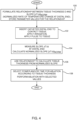
- Fig. 4 is a flowchart of steps followed by professional 14 and the algorithm of processor 46 in performing the ablation procedure referred to above, according to an embodiment of the present invention.
- a preparatory step 100 that is typically performed before the start of the ablation procedure, the relationship between tissue thickness D and normalized slope s, i.e., the normalized rate of temperature change ⁇ T ⁇ t NORM of distal end 22, is formulated.
- values for parameters of the relationship, in this case A and B, as well as parameters for the normalizing relationships are stored as look-up table 70 and/or mathematical model 68, as described above.
- a catheter having a distal end similar to the distal end 22 that is used in the ablation procedure of the present flowchart is used to perform the evaluations and/or generate look-up table 70 and mathematical model 68.
- step 102 professional 14 inserts distal end 22 to contact a selected portion of tissue 15 of myocardium 16, and force module 60 and processor 46 record a contact force CF sensed by force sensor 26.
- the professional sets a flow rate V of irrigation to the distal end.
- V is set within a range 10 - 20 mL/min, but V may have a value outside this range.
- the processor uses electrode 30 to apply a radiofrequency power pulse to the tissue in contact with the distal end. In one embodiment the processor sets the pulse to have a power P of 30 Watts and a duration t of 1 second. The processor records the values of V, P, and t.
- a slope measurement step 104 once the pulse has been applied to tissue 15, the processor begins recording the temperature of the one or more temperature sensors 28, as well as the times of recordation. From the temperatures and the times, the processor evaluates a value of the slope ⁇ T ⁇ t . From the slope, the processor calculates the normalized rate of temperature change ⁇ T ⁇ t NORM , i.e., the normalized slope of the corresponding temperature-time graph, of distal end 22.
- a tissue thickness step 106 the processor applies the normalized slope found in step 104 to the relationship formulated in step 100, together with appropriate values for parameters A, B, of the relationship, to evaluate a thickness D of tissue 15.
- the values of A and B are found from look-up table 70 and/or mathematical model 68.
- an ablation step 108 the processor uses the evaluated tissue thickness D to estimate a radiofrequency power P and a duration time t for which the power is to be applied, to ablate tissue 15.
- the estimation typically uses an ablation index, described below.
- an ablation index is a function, having a value that changes as ablation proceeds, which provides an estimate of the size of a lesion produced by the ablation of a tissue of known type. The estimate provided by the index depends on the values of the contact force CF and power P measured during the ablation, as well as on the period of time of the ablation.
- Ablation indices are described in an article entitled " Ablation Index-guided Pulmonary Vein Isolation for Atrial Fibrillation may Improve Clinical Outcomes in Comparison to Contact Force-guided Ablation" to Hussein et al., presented at the 2016 Heart Rhythm Congress , and in U.S. Patent Application 2017/0014181 to Bar-Tal et al.
- Processor 46 may thus use the right side of equation (4) to provide to professional 14 recommended values of power P and time t for ablation using the measured value of force CF and an estimate of C.
- step 108 professional 14 selects one of the recommended values of power P and time t to ablate tissue 15, and concludes the ablation of tissue 15 with these values.
Landscapes
- Health & Medical Sciences (AREA)
- Life Sciences & Earth Sciences (AREA)
- Surgery (AREA)
- Engineering & Computer Science (AREA)
- Public Health (AREA)
- Animal Behavior & Ethology (AREA)
- Veterinary Medicine (AREA)
- Physics & Mathematics (AREA)
- Biomedical Technology (AREA)
- Heart & Thoracic Surgery (AREA)
- Medical Informatics (AREA)
- Molecular Biology (AREA)
- General Health & Medical Sciences (AREA)
- Biophysics (AREA)
- Pathology (AREA)
- Cardiology (AREA)
- Oral & Maxillofacial Surgery (AREA)
- Dentistry (AREA)
- Plasma & Fusion (AREA)
- Nuclear Medicine, Radiotherapy & Molecular Imaging (AREA)
- Otolaryngology (AREA)
- Surgical Instruments (AREA)
Description
- This invention relates generally to measurements of biological tissue, and specifically to measuring the thickness of the tissue.
- During medical procedures performed on tissue, such as acquisition of a biopsy or ablation of a portion of the myocardium, it may be useful to know the thickness of the tissue. In a number of cases this may be deduced from a pre-acquired image of the tissue, such as from an MRI (magnetic resonance imaging) or a CT (computerized tomography) image. In the case of ablation, this data may not be available to the professional performing the ablation. Even if it is available, it may not give the thickness to sufficient accuracy, or the thickness may have changed since acquisition of the image.
- For further background,
US 2015/088116A describes systems and methods for estimating tissue parameters, including mass of tissue to be treated and a thermal resistance scale factor between the tissue and an electrode of an energy delivery device. -
WO 2016/168435A describes a radio frequency system capable of selectively heating skin and subcutaneous fat tissues using a single frequency dual mode antenna device. -
US 2014/171936A describes an apparatus, consisting of an insertion tube having a distal end configured for insertion into proximity with tissue in a body of a patient and containing a lumen having an electrical conductor for conveying electrical energy to the tissue. -
US 8,388,549B describes a medical device utilizing temperature sensing to identify or assess anatomical bodies or structures includes an elongate tubular member, at least one electrode, a thermal sensor, and a temperature response assessment system or component. The thermal sensor may be configured to measure the thermal response of the portion of an anatomical body or structure, e.g., tissue or blood pools. The temperature response assessment system or component can be coupled to the thermal sensor. - There is provided an apparatus according to independent claim 1. Additional embodiments of the invention are recited in the dependent claims.
- The present disclosure will be more fully understood from the following detailed description of the embodiments thereof, taken together with the drawings, in which:
-
-
Fig. 1 is a schematic illustration of an invasive medical procedure using apparatus, according to an embodiment of the present invention; -
Fig. 2 is a schematic illustration of a distal end of a probe used in the apparatus, according to an embodiment of the present invention; -
Fig. 3 is a schematic graph of tissue thickness vs. slope, according to an embodiment of the present invention; and -
Fig. 4 is a flowchart of steps followed by a professional in performing the procedure, according to an embodiment of the present invention. - Embodiments of the present invention provide an independent measure of the thickness of tissue being investigated, typically in an investigation comprising an ablation procedure. For an ablation procedure the method may be applied while ablation is actually being performed, or while no ablation is occurring. The measure relies on the discovery by the inventor that if a heat energy pulse is injected into tissue from the distal end of a catheter in contact with the tissue, the rate of change of the temperature of the distal end varies according to the thickness of the tissue. I.e., for thick tissue the rate is large, and for thin tissue the rate is small.
- Thus, in a typical procedure using radiofrequency energy for ablating tissue, a catheter distal end is inserted into contact with the tissue to be ablated, and the distal end and the tissue are irrigated at a given rate. During the irrigation a radiofrequency pulse is applied for a short time to the tissue, and the temperature of the catheter distal end, typically a mean temperature calculated from multiple sensors in the distal end, is monitored. The thickness of the tissue is then estimated from the measured rate of change of the temperature of the distal end. The estimation comprises using a relationship between a normalized rate of change of the temperature of the distal end and the thickness of the tissue. The relationship may be determined prior to insertion of the catheter into proximity with the tissue.
- Once the tissue thickness has been estimated, the value of the thickness may be used in estimating the power to be used for the ablation, and the time period over which the power is to be applied, in order to achieve a successful ablation of the tissue.
-
Fig. 1 is a schematic illustration of an invasive medicalprocedure using apparatus 12, andFig. 2 is a schematic illustration of adistal end 22 of aprobe 20 used in the apparatus, according to an embodiment of the present invention. The procedure is performed by amedical professional 14, and in the description hereinbelow the procedure is assumed to comprise an ablation of a portion oftissue 15 of amyocardium 16 of the heart of ahuman patient 18. - In order to perform the investigation, professional 14
inserts probe 20 into asheath 21 that has been pre-positioned in a lumen of the patient. Sheath 21 is positioned so thatdistal end 22 of the probe enters the heart of the patient.Distal end 22 comprises aposition sensor 24 that enables the location and orientation of the distal end to be tracked, aforce sensor 26 that measures the force applied by the distal end when it contacts the myocardium, and one ormore temperature sensors 28 that measure the temperature at respective locations of the distal end.Distal end 22 also comprises anelectrode 30 which is used to deliver radiofrequency ablation power tomyocardium 16 in order to ablate the myocardium. Electrode 30 may also be used to acquire electropotentials from the myocardium, as noted below. -
Apparatus 12 is controlled by asystem processor 46, which is located in anoperating console 48 of the apparatus.Console 48 comprisescontrols 49 which are used by professional 14 to communicate with the processor. The software forprocessor 46 may be downloaded to the processor in electronic form, over a network, for example. Alternatively or additionally, the software may be provided on non-transitory tangible media, such as optical, magnetic, or electronic storage media. The track ofdistal end 22 is typically displayed on a three-dimensional representation 60 of the heart ofpatient 18 that is displayed on ascreen 61. -
System processor 46 comprises real-timenoise reduction circuitry 45, typically configured as a field programmable gate array (FPGA), followed by an analog-to-digital (A/D)) signal conversion integratedcircuit 47. The processor can pass the signal from A/D circuit 47 to another processor and/or can be programmed to perform at least one algorithm disclosed herein, the algorithm comprising steps described hereinbelow. The processor usescircuitry 45 andcircuit 47, as well as features of modules which are described in more detail below, in order to perform the algorithm. - In order to operate
apparatus 12, the algorithm ofprocessor 46 communicates with a module bank 50, which has a number of modules used by the processor to operate the apparatus. Thus, bank 50 comprises an electrocardiograph (ECG)module 56 which acquires and analyzes signals fromelectrode 30, and atracking module 58 which receives and analyzes signals fromposition sensor 24, and which uses the signal analysis to generate a location and an orientation ofdistal end 22. In someembodiments sensor 24 comprises one or more coils which provide the sensor signals in response to magnetic fields traversing the coils. In these embodiments, in addition to receiving and analyzing signals fromsensor 24,tracking module 58 also controlsradiators fields traversing sensor 24. The radiators are positioned in proximity tomyocardium 16, and are configured to radiate alternating magnetic fields into a region in proximity to the myocardium. The Carto® system produced by Biosense Webster, of 33 Technology Drive, Irvine, CA 92618 USA, uses such a magnetic tracking system. - Bank 50 also comprises a
force module 60, apower module 62, anirrigation module 64, and atemperature module 66. The functions of these modules are explained below. The modules in bank 50, andprocessor 46, are herein termedprocessing circuitry 51. -
Force module 60 receives signals fromforce sensor 26, and from the signals generates a magnitude CF of the contact force, herein assumed to be measured in grams, exerted bydistal end 22 ontissue 15. In some embodiments theforce sensor 26 is configured so that the signals it provides tomodule 60 enable the module to evaluate a direction of the force exerted by the distal end ontissue 15. -
Power module 62 comprises a radiofrequency (RF)signal generator 63 which generates the radiofrequency power that is conveyed toelectrode 30, and that is applied by the electrode to ablatetissue 15.Processor 46 andmodule 62 are able to adjust a power level P, herein assumed to be measured in Watts, delivered by the electrode, as well as a length of time t, measured in seconds, during which the power is delivered, as described in more detail below. -
Irrigation module 64 controls a rate of flow V, herein assumed to be measured in mL/min, of irrigation fluid, typically normal saline solution, supplied todistal end 22. The irrigation fluid is expelled fromirrigation holes 80 in the distal end. -
Temperature module 66 receives signals from one ormore temperature sensors 28, and determines the temperatures registered by each of the sensors. Typically, in the case ofmultiple sensors 28 the module determines a mean temperature T ofdistal end 22. Additionally, in the case of multiple sensors, the module may produce a map of the temperature distribution of the distal end. - The inventor has found that on injection of a heat energy pulse into
tissue 15 an overall thickness D of the tissue affects the rate of change of temperature
more sensors 28. In particular, for a given irrigation rate V of fluid through the distal end, and for a given contact force CF applied to the tissue by the distal end, the rate of change of temperature

- The relationship may be expressed by the following equation (1):

- where D is the thickness of the tissue,
- ΔT is the change of temperature of the distal end in a time period Δt, and
- f is a function.
- In one embodiment, the function f is as given in equation (2):

- n is a numerical exponent,
- A, B are constant parameters having values which depend on the thermal characteristics of the distal end of the catheter,
and - s is a normalized slope of a temperature-time graph, i.e.,

- The non-normalized slope of the temperature-time graph,

- The non-normalized slope,


- In an embodiment the numerical exponent n in equation (2) is set as 1 or 2. In other embodiments the value for n may be set to be different from 1 and 2, and may be a non-integer value.
- Values of A and B, as well as the normalized values referred to above, and values of the parameters of the relationships for normalizing the slope

model 68 and/or in a look-up table 70 contained in amemory 72 that is accessed byprocessor 46. -
Fig. 3 is a schematic graph of D vs. s, as determined from equation (2), for n = 1, according to an embodiment of the present invention. As is illustrated in the graph, the slope s,
- For clarity and simplicity, except where otherwise stated, the following description assumes that the relationship between the tissue thickness and the rate of change of temperature is as given by equation (2) with n = 1. Those having ordinary skill in the art will be able to modify the description, mutatis mutandis, for other values of n and for other relationships of the form of equation (1) .
- Prior to performing an actual ablation procedure, professional 14 may determine values for A and B in equation (2), as well as values for the relationships used for normalizing the slope


- In one embodiment the values for V are set within a range 10 - 20 mL/min, the values of P are set within a range of 20 - 30 W, the pulse length t is set within a range of 1 - 3 s, the contact force CF is within a range of 5 - 25 grams, and the normalized values are set at VNORM = 15 mL/min, PNORM = 25 W, tNORM = 2 s, and CFNORM = 15 grams. However, providing that the temperature of the tissue being used remains between approximately 40°C - 60°C, V, P, and t may have values outside these ranges, and the normalized values may be different from those provided here, and such alternative values may be determined by one with ordinary skill in the art without undue experimentation.
- To determine A and B for a selected catheter, the distal end of the catheter is brought into contact with tissue of a known thickness D, and the distal end is configured to exert the normalized contact force CFNORM on the tissue while the distal end and tissue are irrigated at the normalized irrigation rate VNORM. A radiofrequency pulse with the normalized power PNORM and pulse length tNORM is applied to the tissue, and the temperature T of the distal end is recorded as it changes over time. From the recordation of the distal end temperatures and times, an estimate of the normalized slope,


- The above determination is repeated for different values of tissue thickness D, giving respective different values of

- For each selected catheter, professional 14 may use
processor 46 to store the respective values of A, B, as mathematical model 68 (Fig. 1 ).Model 68 is a mathematical function, such as a cost function, that enables the processor to determine values of A and B from the experimental values of V, P, t and CF, together with values for the respective normalizing relationships to the normalized values VNORM, PNORM, tNORM and CFNORM, as described above. Alternatively or additionally, professional 14 may configure the processor to store the respective values of A and B for each selected catheter, as well as the values for the respective relationships in a look-up table 70. -
Fig. 4 is a flowchart of steps followed by professional 14 and the algorithm ofprocessor 46 in performing the ablation procedure referred to above, according to an embodiment of the present invention. In apreparatory step 100 that is typically performed before the start of the ablation procedure, the relationship between tissue thickness D and normalized slope s, i.e., the normalized rate of temperature change
distal end 22, is formulated. As stated above, for simplicity and clarity the relationship herein is assumed to correspond to equation (2) with n = 1. In addition to formulating the relationship, instep 100 values for parameters of the relationship, in this case A and B, as well as parameters for the normalizing relationships are stored as look-up table 70 and/ormathematical model 68, as described above. Typically a catheter having a distal end similar to thedistal end 22 that is used in the ablation procedure of the present flowchart is used to perform the evaluations and/or generate look-up table 70 andmathematical model 68. - In an
initial procedure step 102, professional 14 insertsdistal end 22 to contact a selected portion oftissue 15 ofmyocardium 16, andforce module 60 andprocessor 46 record a contact force CF sensed byforce sensor 26. Once in contact withtissue 15, the professional sets a flow rate V of irrigation to the distal end. Typically, the value for V is set within a range 10 - 20 mL/min, but V may have a value outside this range. In addition, while the distal end and the tissue are being irrigated, the processor useselectrode 30 to apply a radiofrequency power pulse to the tissue in contact with the distal end. In one embodiment the processor sets the pulse to have a power P of 30 Watts and a duration t of 1 second. The processor records the values of V, P, and t. - In a
slope measurement step 104, once the pulse has been applied totissue 15, the processor begins recording the temperature of the one ormore temperature sensors 28, as well as the times of recordation. From the temperatures and the times, the processor evaluates a value of the slope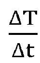

distal end 22. - In a
tissue thickness step 106, the processor applies the normalized slope found instep 104 to the relationship formulated instep 100, together with appropriate values for parameters A, B, of the relationship, to evaluate a thickness D oftissue 15. For the relationship corresponding to equation (2) with n = 1, the values of A and B are found from look-up table 70 and/ormathematical model 68. - In an
ablation step 108 the processor uses the evaluated tissue thickness D to estimate a radiofrequency power P and a duration time t for which the power is to be applied, to ablatetissue 15. The estimation typically uses an ablation index, described below. - As is known in the art, an ablation index is a function, having a value that changes as ablation proceeds, which provides an estimate of the size of a lesion produced by the ablation of a tissue of known type. The estimate provided by the index depends on the values of the contact force CF and power P measured during the ablation, as well as on the period of time of the ablation. Ablation indices are described in an article entitled "Ablation Index-guided Pulmonary Vein Isolation for Atrial Fibrillation may Improve Clinical Outcomes in Comparison to Contact Force-guided Ablation" to Hussein et al., presented at the 2016 Heart Rhythm Congress, and in
U.S. Patent Application 2017/0014181 to Bar-Tal et al. - Equation (3) below gives an expression for an ablation index:

- where C is a constant having a value depending on the type of tissue being ablated; in one embodiment C has an approximate value of 0.002,
- α is an exponent having a value typically in the range 0.6 - 0.8,
- β is an exponent having a value typically in the range 1.4 - 1.8,
- δ is an exponent having an approximate value of 0.35, and
- D is an estimate of the depth of a lesion achieved by ablating for a time t, with instantaneous contact force CF(τ) and instantaneous power P(τ), and where τ represents a time variable.
- If the contact force and the power are assumed to be constant, having respective values
CF andP during an ablation procedure that is to take a time t, then equation (3) may be rewritten as equation (4):
- The value of the left side of equation (4), tissue thickness D, is known from
step 106.Processor 46 may thus use the right side of equation (4) to provide to professional 14 recommended values of power P and time t for ablation using the measured value of force CF and an estimate of C. - In
step 108 professional 14 selects one of the recommended values of power P and time t to ablatetissue 15, and concludes the ablation oftissue 15 with these values. - The description above of steps of the flowchart assumes that professional 14 uses an ablation index in determining values of power to be applied during an ablation procedure. The ablation index acts as an aid to the professional in deciding values of parameters, such as power and time period of ablation, to be used during an ablation procedure. However, it will be understood that the professional may not use an ablation index in deciding values of such parameters, while still using the description of
tissue thickness step 106 to estimate the thickness of tissue being ablated, and may adapt the flowchart description, mutatis mutandis, for such a case. It will thus be understood that the scope of the present invention includes cases where an ablation index is not used. - The description above has also assumed that the rate of change of temperature of the catheter distal end, i.e., the slope of the temperature-time graph, is normalized. Nevertheless, those having ordinary skill in the art will be able to adapt the description to accommodate cases , which are not within the scope of the invention, where the rate of change of temperature of the catheter distal end is not normalized.
- It will thus be appreciated that the embodiments described above are cited by way of example, and that the present invention is not limited to what has been particularly shown and described hereinabove. Rather, the scope of the disclosure includes both combinations and subcombinations of the various features described hereinabove, as well as variations and modifications thereof which would occur to persons skilled in the art upon reading the foregoing description and which are not disclosed in the prior art. The scope of the present invention is nevertheless defined by the appended claims.
Claims (6)
- Apparatus (12), comprising:a radiofrequency ablation catheter (20) having a distal end (22) configured to be inserted into contact with tissue to be ablated, the distal end comprising a force sensor configured to measure the force applied by the distal end;an electrode (30) attached to the distal end (22);a temperature sensor (28) incorporated in the distal end (22) and configured to output a temperature signal; andprocessing circuitry (51) comprising:a force module (60) configured to receive signals from the force sensor and generate a magnitude of the contact force,a power module (62) comprising a radiofrequency (RF) signal generator (63) configured to apply a pulse of RF electrical energy via the electrode (30) to the tissue, so as to heat the tissue,an irrigation module (64) configured to control a rate of flow of irrigation fluid supplied to the distal end,a temperature module (66) configured to receive the temperature signal and determine a temperature registered by the temperature sensor, anda processor (64),characterized in that the processing circuitry (51) is configured to compute, based on the temperature registered by the temperature sensor, a rate of temperature change of the distal end (22) following termination of the pulse,wherein the rate of temperature change is a function of the magnitude of the contact force, a power level applied by the generator, a length of time of the pulse, and the rate of flow of irrigation fluid supplied to the distal end,wherein the processing circuitry (51) is configured to determine a normalized rate of temperature change from the rate of temperature change based upon a direct proportionality for the magnitude of the contact force, the power level, and the length of time of the pulse, and an inverse proportionality for the rate of flow of irrigation fluid supplied to the distal end,wherein the processing circuitry (51) is configured to estimate a thickness of the tissue using a relationship between the normalized rate of temperature change and thickness of the tissue.
- The apparatus (12) according to claim 1, wherein estimating the thickness of the tissue is based upon the rate of temperature change increasing as the thickness increases.
- The apparatus (12) according to claim 1, wherein estimating the thickness is based upon a mathematical relationship between the tissue thickness and the rate of temperature change, and wherein the mathematical relationship comprises parameters depending on thermal characteristics of the distal end (22).
- The apparatus (12) according to claim 1, wherein, to apply the pulse of RF electrical energy, the RF signal generator (63) is configured to apply a preset RF power level for a first preset time period, and wherein, to compute the rate of temperature change of the distal end (22), the processing circuitry (46) is configured to record the temperature signal for a second preset time period beginning on termination of the pulse.
- The apparatus (12) according to claim 1, wherein the processing circuitry (46) is configured to set a power level to be supplied by the RF signal generator (63) for ablation of the tissue, and a time for the ablation, in response the estimated thickness of the tissue.
- The apparatus (12) according to claim 1, wherein the radiofrequency ablation catheter (20) has a distal end (22) configured to be inserted into contact with a portion of tissue (15) of a myocardium (16) of a human heart to be ablated.
Applications Claiming Priority (2)
| Application Number | Priority Date | Filing Date | Title |
|---|---|---|---|
| US201762470983P | 2017-03-14 | 2017-03-14 | |
| US15/896,687 US11185366B2 (en) | 2017-03-14 | 2018-02-14 | Estimation of tissue thickness from rate of change of catheter temperature |
Publications (3)
| Publication Number | Publication Date |
|---|---|
| EP3375397A1 EP3375397A1 (en) | 2018-09-19 |
| EP3375397B1 true EP3375397B1 (en) | 2024-07-31 |
| EP3375397C0 EP3375397C0 (en) | 2024-07-31 |
Family
ID=61628228
Family Applications (1)
| Application Number | Title | Priority Date | Filing Date |
|---|---|---|---|
| EP18161510.5A Active EP3375397B1 (en) | 2017-03-14 | 2018-03-13 | Estimation of tissue thickness from rate of change of catheter temperature |
Country Status (7)
| Country | Link |
|---|---|
| US (1) | US11185366B2 (en) |
| EP (1) | EP3375397B1 (en) |
| JP (1) | JP7114281B2 (en) |
| CN (1) | CN108720838A (en) |
| AU (1) | AU2018201564A1 (en) |
| CA (1) | CA2998011A1 (en) |
| IL (1) | IL257875B (en) |
Families Citing this family (6)
| Publication number | Priority date | Publication date | Assignee | Title |
|---|---|---|---|---|
| US20200155223A1 (en) * | 2018-11-20 | 2020-05-21 | Biosense Webster (Israel) Ltd. | Irrigation control during ablation |
| US20200155225A1 (en) * | 2018-11-20 | 2020-05-21 | Biosense Webster (Israel) Ltd. | Irrigation control during ablation |
| US11413098B2 (en) | 2018-12-07 | 2022-08-16 | Biosense Webster (Israel) Ltd. | Semi-automated ablation system |
| US20210085215A1 (en) * | 2019-09-22 | 2021-03-25 | Biosense Webster (Israel) Ltd. | Ecg-based cardiac wall thickness estimation |
| CN111557734B (en) * | 2020-05-07 | 2021-11-02 | 徐州佳智信息科技有限公司 | A laser ablation navigation system based on VR scene |
| US12150702B1 (en) | 2024-06-03 | 2024-11-26 | Physcade, Inc. | Generator and catheter for tissue ablation |
Citations (3)
| Publication number | Priority date | Publication date | Assignee | Title |
|---|---|---|---|---|
| US20040267191A1 (en) * | 2003-03-27 | 2004-12-30 | Cierra, Inc. | Methods and apparatus for treatment of patent foramen ovale |
| US20120232339A1 (en) * | 2009-09-02 | 2012-09-13 | Laszlo Csiky | Surgical device and accessories |
| US8388549B2 (en) * | 2008-12-29 | 2013-03-05 | St. Jude Medical, Atrial Fibrillation Division, Inc. | Anatomical thermal sensing device and method |
Family Cites Families (12)
| Publication number | Priority date | Publication date | Assignee | Title |
|---|---|---|---|---|
| US8388542B2 (en) | 2009-05-04 | 2013-03-05 | Siemens Medical Solutions Usa, Inc. | System for cardiac pathology detection and characterization |
| US8545408B2 (en) * | 2011-05-23 | 2013-10-01 | St. Jude Medical, Inc. | Combination catheter for forward and side lesioning with acoustic lesion feedback capability |
| US8545409B2 (en) | 2011-04-14 | 2013-10-01 | St. Jude Medical, Inc. | Arrangement and interface for RF ablation system with acoustic feedback |
| US20140142438A1 (en) | 2012-11-19 | 2014-05-22 | Biosense Webster (Israel), Ltd. | Using location and force measurements to estimate tissue thickness |
| US9445725B2 (en) | 2012-12-17 | 2016-09-20 | Biosense Webster (Israel) Ltd. | Irrigated catheter tip with temperature sensor array |
| US20140171936A1 (en) | 2012-12-17 | 2014-06-19 | Biosense Webster (Israel) Ltd. | Irrigated catheter tip with temperature sensor and optic fiber arrays |
| US9867651B2 (en) * | 2013-09-26 | 2018-01-16 | Covidien Lp | Systems and methods for estimating tissue parameters using surgical devices |
| US10130412B2 (en) | 2013-09-26 | 2018-11-20 | Covidien Lp | Systems and methods for estimating tissue parameters using surgical devices |
| EP3258837A4 (en) * | 2015-02-20 | 2018-10-10 | Mc10, Inc. | Automated detection and configuration of wearable devices based on on-body status, location, and/or orientation |
| US9813832B2 (en) * | 2015-02-23 | 2017-11-07 | Te Connectivity Corporation | Mating assurance system and method |
| WO2016168435A1 (en) | 2015-04-14 | 2016-10-20 | Crysanthe, Inc. | System and method for selective treatment of skin and subcutaneous fat using a single frequency dual mode radio frequency antenna device |
| US10517670B2 (en) | 2015-07-16 | 2019-12-31 | Biosense Webster (Israel) Ltd. | Estimation of lesion size |
-
2018
- 2018-02-14 US US15/896,687 patent/US11185366B2/en active Active
- 2018-03-05 AU AU2018201564A patent/AU2018201564A1/en not_active Abandoned
- 2018-03-05 IL IL257875A patent/IL257875B/en unknown
- 2018-03-13 JP JP2018045094A patent/JP7114281B2/en active Active
- 2018-03-13 EP EP18161510.5A patent/EP3375397B1/en active Active
- 2018-03-13 CA CA2998011A patent/CA2998011A1/en not_active Abandoned
- 2018-03-14 CN CN201810210222.4A patent/CN108720838A/en active Pending
Patent Citations (3)
| Publication number | Priority date | Publication date | Assignee | Title |
|---|---|---|---|---|
| US20040267191A1 (en) * | 2003-03-27 | 2004-12-30 | Cierra, Inc. | Methods and apparatus for treatment of patent foramen ovale |
| US8388549B2 (en) * | 2008-12-29 | 2013-03-05 | St. Jude Medical, Atrial Fibrillation Division, Inc. | Anatomical thermal sensing device and method |
| US20120232339A1 (en) * | 2009-09-02 | 2012-09-13 | Laszlo Csiky | Surgical device and accessories |
Also Published As
| Publication number | Publication date |
|---|---|
| JP7114281B2 (en) | 2022-08-08 |
| EP3375397C0 (en) | 2024-07-31 |
| IL257875A (en) | 2018-04-30 |
| AU2018201564A1 (en) | 2018-10-04 |
| EP3375397A1 (en) | 2018-09-19 |
| JP2018149300A (en) | 2018-09-27 |
| CN108720838A (en) | 2018-11-02 |
| IL257875B (en) | 2022-02-01 |
| US20180263690A1 (en) | 2018-09-20 |
| US11185366B2 (en) | 2021-11-30 |
| CA2998011A1 (en) | 2018-09-14 |
Similar Documents
| Publication | Publication Date | Title |
|---|---|---|
| US11185366B2 (en) | Estimation of tissue thickness from rate of change of catheter temperature | |
| US11911097B2 (en) | Estimation of tissue thickness | |
| EP3662855B1 (en) | Semi-automated ablation system | |
| JP2019076731A (en) | Esophageal probe with transmitting coils | |
| CN107485389B (en) | Identification and visualization of cardiac activation sequences in multi-channel recordings | |
| EP3434214B1 (en) | Tissue thickness using pulsed power | |
| EP3216413B1 (en) | Ablation probe with a position sensor and with means for magnetic resonance thermometry | |
| EP3699926A1 (en) | Cardiac mapping and ablation | |
| JP7631044B2 (en) | Measurement of cardiac wall tissue thickness during ablation |
Legal Events
| Date | Code | Title | Description |
|---|---|---|---|
| PUAI | Public reference made under article 153(3) epc to a published international application that has entered the european phase |
Free format text: ORIGINAL CODE: 0009012 |
|
| STAA | Information on the status of an ep patent application or granted ep patent |
Free format text: STATUS: THE APPLICATION HAS BEEN PUBLISHED |
|
| AK | Designated contracting states |
Kind code of ref document: A1 Designated state(s): AL AT BE BG CH CY CZ DE DK EE ES FI FR GB GR HR HU IE IS IT LI LT LU LV MC MK MT NL NO PL PT RO RS SE SI SK SM TR |
|
| AX | Request for extension of the european patent |
Extension state: BA ME |
|
| STAA | Information on the status of an ep patent application or granted ep patent |
Free format text: STATUS: REQUEST FOR EXAMINATION WAS MADE |
|
| 17P | Request for examination filed |
Effective date: 20190311 |
|
| RBV | Designated contracting states (corrected) |
Designated state(s): AL AT BE BG CH CY CZ DE DK EE ES FI FR GB GR HR HU IE IS IT LI LT LU LV MC MK MT NL NO PL PT RO RS SE SI SK SM TR |
|
| STAA | Information on the status of an ep patent application or granted ep patent |
Free format text: STATUS: EXAMINATION IS IN PROGRESS |
|
| 17Q | First examination report despatched |
Effective date: 20201203 |
|
| GRAP | Despatch of communication of intention to grant a patent |
Free format text: ORIGINAL CODE: EPIDOSNIGR1 |
|
| STAA | Information on the status of an ep patent application or granted ep patent |
Free format text: STATUS: GRANT OF PATENT IS INTENDED |
|
| INTG | Intention to grant announced |
Effective date: 20240221 |
|
| GRAS | Grant fee paid |
Free format text: ORIGINAL CODE: EPIDOSNIGR3 |
|
| GRAA | (expected) grant |
Free format text: ORIGINAL CODE: 0009210 |
|
| STAA | Information on the status of an ep patent application or granted ep patent |
Free format text: STATUS: THE PATENT HAS BEEN GRANTED |
|
| AK | Designated contracting states |
Kind code of ref document: B1 Designated state(s): AL AT BE BG CH CY CZ DE DK EE ES FI FR GB GR HR HU IE IS IT LI LT LU LV MC MK MT NL NO PL PT RO RS SE SI SK SM TR |
|
| REG | Reference to a national code |
Ref country code: CH Ref legal event code: EP Ref country code: GB Ref legal event code: FG4D |
|
| REG | Reference to a national code |
Ref country code: DE Ref legal event code: R096 Ref document number: 602018072371 Country of ref document: DE |
|
| REG | Reference to a national code |
Ref country code: IE Ref legal event code: FG4D |
|
| U01 | Request for unitary effect filed |
Effective date: 20240816 |
|
| U07 | Unitary effect registered |
Designated state(s): AT BE BG DE DK EE FI FR IT LT LU LV MT NL PT RO SE SI Effective date: 20240902 |
|
| PG25 | Lapsed in a contracting state [announced via postgrant information from national office to epo] |
Ref country code: NO Free format text: LAPSE BECAUSE OF FAILURE TO SUBMIT A TRANSLATION OF THE DESCRIPTION OR TO PAY THE FEE WITHIN THE PRESCRIBED TIME-LIMIT Effective date: 20241031 |
|
| PG25 | Lapsed in a contracting state [announced via postgrant information from national office to epo] |
Ref country code: PL Free format text: LAPSE BECAUSE OF FAILURE TO SUBMIT A TRANSLATION OF THE DESCRIPTION OR TO PAY THE FEE WITHIN THE PRESCRIBED TIME-LIMIT Effective date: 20240731 Ref country code: GR Free format text: LAPSE BECAUSE OF FAILURE TO SUBMIT A TRANSLATION OF THE DESCRIPTION OR TO PAY THE FEE WITHIN THE PRESCRIBED TIME-LIMIT Effective date: 20241101 |
|
| PG25 | Lapsed in a contracting state [announced via postgrant information from national office to epo] |
Ref country code: IS Free format text: LAPSE BECAUSE OF FAILURE TO SUBMIT A TRANSLATION OF THE DESCRIPTION OR TO PAY THE FEE WITHIN THE PRESCRIBED TIME-LIMIT Effective date: 20241130 |
|
| PG25 | Lapsed in a contracting state [announced via postgrant information from national office to epo] |
Ref country code: HR Free format text: LAPSE BECAUSE OF FAILURE TO SUBMIT A TRANSLATION OF THE DESCRIPTION OR TO PAY THE FEE WITHIN THE PRESCRIBED TIME-LIMIT Effective date: 20240731 |
|
| PG25 | Lapsed in a contracting state [announced via postgrant information from national office to epo] |
Ref country code: RS Free format text: LAPSE BECAUSE OF FAILURE TO SUBMIT A TRANSLATION OF THE DESCRIPTION OR TO PAY THE FEE WITHIN THE PRESCRIBED TIME-LIMIT Effective date: 20241031 Ref country code: ES Free format text: LAPSE BECAUSE OF FAILURE TO SUBMIT A TRANSLATION OF THE DESCRIPTION OR TO PAY THE FEE WITHIN THE PRESCRIBED TIME-LIMIT Effective date: 20240731 |
|
| PG25 | Lapsed in a contracting state [announced via postgrant information from national office to epo] |
Ref country code: RS Free format text: LAPSE BECAUSE OF FAILURE TO SUBMIT A TRANSLATION OF THE DESCRIPTION OR TO PAY THE FEE WITHIN THE PRESCRIBED TIME-LIMIT Effective date: 20241031 Ref country code: PL Free format text: LAPSE BECAUSE OF FAILURE TO SUBMIT A TRANSLATION OF THE DESCRIPTION OR TO PAY THE FEE WITHIN THE PRESCRIBED TIME-LIMIT Effective date: 20240731 Ref country code: NO Free format text: LAPSE BECAUSE OF FAILURE TO SUBMIT A TRANSLATION OF THE DESCRIPTION OR TO PAY THE FEE WITHIN THE PRESCRIBED TIME-LIMIT Effective date: 20241031 Ref country code: IS Free format text: LAPSE BECAUSE OF FAILURE TO SUBMIT A TRANSLATION OF THE DESCRIPTION OR TO PAY THE FEE WITHIN THE PRESCRIBED TIME-LIMIT Effective date: 20241130 Ref country code: HR Free format text: LAPSE BECAUSE OF FAILURE TO SUBMIT A TRANSLATION OF THE DESCRIPTION OR TO PAY THE FEE WITHIN THE PRESCRIBED TIME-LIMIT Effective date: 20240731 Ref country code: GR Free format text: LAPSE BECAUSE OF FAILURE TO SUBMIT A TRANSLATION OF THE DESCRIPTION OR TO PAY THE FEE WITHIN THE PRESCRIBED TIME-LIMIT Effective date: 20241101 Ref country code: ES Free format text: LAPSE BECAUSE OF FAILURE TO SUBMIT A TRANSLATION OF THE DESCRIPTION OR TO PAY THE FEE WITHIN THE PRESCRIBED TIME-LIMIT Effective date: 20240731 |
|
| U20 | Renewal fee for the european patent with unitary effect paid |
Year of fee payment: 8 Effective date: 20250205 |
|
| PG25 | Lapsed in a contracting state [announced via postgrant information from national office to epo] |
Ref country code: SM Free format text: LAPSE BECAUSE OF FAILURE TO SUBMIT A TRANSLATION OF THE DESCRIPTION OR TO PAY THE FEE WITHIN THE PRESCRIBED TIME-LIMIT Effective date: 20240731 |
|
| PG25 | Lapsed in a contracting state [announced via postgrant information from national office to epo] |
Ref country code: CZ Free format text: LAPSE BECAUSE OF FAILURE TO SUBMIT A TRANSLATION OF THE DESCRIPTION OR TO PAY THE FEE WITHIN THE PRESCRIBED TIME-LIMIT Effective date: 20240731 |
|
| PG25 | Lapsed in a contracting state [announced via postgrant information from national office to epo] |
Ref country code: SK Free format text: LAPSE BECAUSE OF FAILURE TO SUBMIT A TRANSLATION OF THE DESCRIPTION OR TO PAY THE FEE WITHIN THE PRESCRIBED TIME-LIMIT Effective date: 20240731 |
|
| PLBE | No opposition filed within time limit |
Free format text: ORIGINAL CODE: 0009261 |
|
| STAA | Information on the status of an ep patent application or granted ep patent |
Free format text: STATUS: NO OPPOSITION FILED WITHIN TIME LIMIT |
|
| 26N | No opposition filed |
Effective date: 20250501 |
|
| PG25 | Lapsed in a contracting state [announced via postgrant information from national office to epo] |
Ref country code: MC Free format text: LAPSE BECAUSE OF FAILURE TO SUBMIT A TRANSLATION OF THE DESCRIPTION OR TO PAY THE FEE WITHIN THE PRESCRIBED TIME-LIMIT Effective date: 20240731 |
|
| REG | Reference to a national code |
Ref country code: CH Ref legal event code: H13 Free format text: ST27 STATUS EVENT CODE: U-0-0-H10-H13 (AS PROVIDED BY THE NATIONAL OFFICE) Effective date: 20251023 |
|
| PG25 | Lapsed in a contracting state [announced via postgrant information from national office to epo] |
Ref country code: CH Free format text: LAPSE BECAUSE OF NON-PAYMENT OF DUE FEES Effective date: 20250331 |
|
| PG25 | Lapsed in a contracting state [announced via postgrant information from national office to epo] |
Ref country code: IE Free format text: LAPSE BECAUSE OF NON-PAYMENT OF DUE FEES Effective date: 20250313 |
|
| U20 | Renewal fee for the european patent with unitary effect paid |
Year of fee payment: 9 Effective date: 20260209 |
|
| PGFP | Annual fee paid to national office [announced via postgrant information from national office to epo] |
Ref country code: GB Payment date: 20260202 Year of fee payment: 9 |