EP3375320B1 - Epilating device and method - Google Patents
Epilating device and method Download PDFInfo
- Publication number
- EP3375320B1 EP3375320B1 EP18162220.0A EP18162220A EP3375320B1 EP 3375320 B1 EP3375320 B1 EP 3375320B1 EP 18162220 A EP18162220 A EP 18162220A EP 3375320 B1 EP3375320 B1 EP 3375320B1
- Authority
- EP
- European Patent Office
- Prior art keywords
- disc
- axle
- axis
- pincers
- discs
- Prior art date
- Legal status (The legal status is an assumption and is not a legal conclusion. Google has not performed a legal analysis and makes no representation as to the accuracy of the status listed.)
- Active
Links
Images


Classifications
-
- A—HUMAN NECESSITIES
- A45—HAND OR TRAVELLING ARTICLES
- A45D—HAIRDRESSING OR SHAVING EQUIPMENT; EQUIPMENT FOR COSMETICS OR COSMETIC TREATMENTS, e.g. FOR MANICURING OR PEDICURING
- A45D26/00—Hair-singeing apparatus; Apparatus for removing superfluous hair, e.g. tweezers
- A45D26/0023—Hair-singeing apparatus; Apparatus for removing superfluous hair, e.g. tweezers with rotating clamping elements
- A45D26/0028—Hair-singeing apparatus; Apparatus for removing superfluous hair, e.g. tweezers with rotating clamping elements with rotating discs or blades
-
- A—HUMAN NECESSITIES
- A45—HAND OR TRAVELLING ARTICLES
- A45D—HAIRDRESSING OR SHAVING EQUIPMENT; EQUIPMENT FOR COSMETICS OR COSMETIC TREATMENTS, e.g. FOR MANICURING OR PEDICURING
- A45D26/00—Hair-singeing apparatus; Apparatus for removing superfluous hair, e.g. tweezers
- A45D26/0023—Hair-singeing apparatus; Apparatus for removing superfluous hair, e.g. tweezers with rotating clamping elements
- A45D26/0033—Hair-singeing apparatus; Apparatus for removing superfluous hair, e.g. tweezers with rotating clamping elements with rollers
- A45D26/0038—Hair-singeing apparatus; Apparatus for removing superfluous hair, e.g. tweezers with rotating clamping elements with rollers power-driven
-
- A—HUMAN NECESSITIES
- A45—HAND OR TRAVELLING ARTICLES
- A45D—HAIRDRESSING OR SHAVING EQUIPMENT; EQUIPMENT FOR COSMETICS OR COSMETIC TREATMENTS, e.g. FOR MANICURING OR PEDICURING
- A45D26/00—Hair-singeing apparatus; Apparatus for removing superfluous hair, e.g. tweezers
- A45D2026/008—Details of apparatus for removing superfluous hair
Definitions
- the invention is directed to an epilating head for an epilating device especially to an epilating head comprising a group of pincer assemblies.
- Depilating devices use one of two methods for removing hair. In one method, the hair is cut, leaving the roots intact beneath the skin surface. In the other method, hair is removed by pulling it out from its roots.
- Disc mechanisms are often used. In general, these mechanisms include discs and associated pincer-like elements. When two pincer-like elements are brought close together, hair is trapped between them. The discs, which rotate and produce a torque, then uproot the hair trapped between their associated pincers. The pincer-like elements and their associated discs move in unison and all pincer-like elements within a fixed distance move close to their adjacent pincer-like elements synchronously. The forces required in such mechanisms are multiples of the number of pincers. In some of these depilatory devices, the disc mechanisms have cylindrical shapes. Other depilating devices which use disc mechanisms employ a large spring with bearings connected to its ends.
- the magnitude of the force is the same throughout the entire mechanism.
- the forces required in such mechanisms are relatively small and the energy required is not great.
- a depilatory device using a disc mechanism is subject to several constraints.
- the pincer-like elements associated with each disc must close quickly.
- the pressure exerted by each contacting pair of pincers must be neither too great nor too little. In the former case, the hair would be cut, while in the latter case, the hair would slide through without being pulled out at its roots.
- all the pincers associated with a row of discs must contact their adjacent pincers simultaneously.
- the contacting mechanism must be simple, operate reliably over time, and be easy to maintain.
- an epilator comprising a head for trapping hair for removal.
- the head comprises a rotating body that has as an axis of rotation and is adapted to be rotated by a motor.
- At least one pair of pincers is arranged at or in the rotating body.
- the pair of pincers is able to rotate in accordance with the rotation of the rotating body.
- At least their outermost ends are adapted to move towards each other and away from each other depending on the location of the rotating body.
- at least one intermediate member is provided which is arranged such that it is at least linearly moveable between the outermost ends of the pincers.
- the pair of pincers only extends on one side of the axis of rotation.
- One spring is located between the pair of pincers and is arranged to bias the pincers either away from each other or towards each other.
- At least one actuator is provided for the pair of pincers which can be supported to move along or parallel to the axis of rotation and engages a first pincer adjacent an end thereof being distal to the axis of rotation and a second pincer at or adjacent an end thereof being proximal to the axis of rotation.
- the epilating device includes a single housing that is shaped to be grasped by the hand of a user and which includes a drive source.
- the housing can carry a first epilation module provided at its top with a first plucking head that is driven by the drive source to effect the plucking of the body hairs.
- the first plucking head has a length defining there along a first epilation zone.
- a second epilation module to be carried on the housing that is provided at its top with a second plucking head that is driven commonly by the drive source to effect plucking of the body hairs.
- the second plucking head has a length defining there along a second epilation zone.
- EP 1 405 701 B1 relates to a linkage mechanism for a hair removal appliance, such as a powered or dry shaver or epilator, having a head rockably mounted on a body, and to such hair depilation apparatus.
- a hair removal appliance such as a powered or dry shaver or epilator
- the device and method realizes a rocking about a virtual pivot axis.
- WO 2005/063076 is directed to a depilator assembly for trapping hair for removal.
- the assembly includes a symmetric disc formed of two lobes and two pincers. At least two pressure-transferring protrusions and at least one rotation transferring protrusion are formed and positioned on a first face of said disc. Further rat least two pressure-transferring protrusions and at least two spacer elements are formed and positioned on a second face of said disc. The spacer elements being operative to prevent the accumulation of debris between adjacent discs and to allow for periodic tilting of the discs when pressure is provided to the depilator assembly.
- the second face of the disc further has formed therein at least one recess configured to accommodate said at least one rotation-transferring protrusions of a similar disc of an adjacent depilator assembly in force transferring engagement, such that, in response to a rotational force applied to said assembly at least one rotation-transferring protrusion is operative to transfer rotation to said adjacent assembly.
- WO 2015/121851 relates to an epilator comprising a pair of corresponding and separable epilator heads for trapping hair for removal.
- Each head has an exposed portion for allowing at least one or more parts of each head to get in touch with a user's skin.
- Each head has a rotating body having an axis of rotation and being adapted to be rotated by a driving unit, wherein the rotating body is adapted to trap the hair for removal at the exposed portion, and wherein the axis of the rotating body is essentially concave relative to the exposed portion of each head.
- the present invention is directed to an epilating head according to claim 1, a pincer assembly according to claim 14 and a method according to claim 15.
- the present invention is directed to an epilating head for an epilating device. It can comprise the following features or any subgroup thereof.
- the first disc can be configured to be rotatable around an axle of rotation or around an axis of rotation.
- the axle does not rotate and the disc can rotate around the axle or can be arranged on an element rotating together with the disc around the axle.
- the axle In the second case the axle can rotate itself.
- it is not curved, it could be made of segments or an elastic material in order to allow it to rotate.
- the disc can be arranged directly on the axle and rotate with axle.
- the pincers can rotate around the axle of rotation.
- the pincers can be arranged at least a counter element or a second disc with at least two counterparts or second disc pincers.
- the counter element or second disc can be configured to be rotatable around the axle or the axis, as described before.
- counter element or disc is not limited to a flat piece of material but can have a considerable thickness. Moreover, it can have any topography and not just two planes with protrusions, e.g. the protrusions being cold drawn or formed in a body.
- the first and the counter element or second discs can be configured so that a first pair is composed of one of the first disc pincers and of one of the counterparts or second disc pincer to form a first tweezer.
- a first pair is composed of one of the first disc pincers and of one of the counterparts or second disc pincer to form a first tweezer.
- neighboring pincers of different discs can form a tweezer.
- a second pair composed of one of the first disc pincers and one of the further counterparts or second disc pincer can form a second tweezer.
- the pincers formed at the discs can be provided in any way, either by providing a flat material, punch it and then deform the parts thereof into different directions or planes.
- the first and second tweezers can each be brought in an open condition over at least a first section of rotation around the axle or axis.
- the first and second tweezers each can be in a closed condition over a second section of rotation around the axle or axis.
- the opening of the tweezers is intended to happen when hair of a user is either brought into the tweezers or released from the tweezers once the hairs are plugged out.
- the closing is intended to primarily take place during the gripping of hair and the remaining in the closed position is intended to primarily take place when plugging or epilating/depilating of hair.
- the first and second tweezers can open and close at different times although they can open at similar or neighboring locations during rotation of the discs.
- the first tweezer and the second tweezer are at least one of axially offset, their envelopes of rotation are neighboring or their envelopes of rotation are side by side. Thus, they are offset and/or their envelopes of rotation do not coincide but are arranged in an axial neighborhood or side by side. This can ensure that the body or skin of a user will be depilated easier and more effectively as the device will treat a surface of the body or skin more equally and completely.
- the first disc pincers can be formed by first disc protrusions radially extending at least in part from the first disc.
- the second disc pincers are formed by second disc protrusions radially extending at least in part from the second disc. Neighboring first disc pincers and/or neighboring second disc pincers can be axially offset to each other. This can ensure that the tweezers formed by the pincers become active not at the same location of the skin but at neighboring locations. Thus the surface of a user's skin is more equally and completely treated over a width of the epilating head without making it necessary for the user to considerably move the device during use.
- the epilating device can also comprise a third disc with at least two third disc pincers. Also a further disc could be provided. Anyhow, the third disc can be rotatable around the axis or axle of rotation. In this case the first and the third discs can be configured that a third pair composed of one of the first disc pincers and one of the third disc pincers form a third tweezer and a fourth pair composed of one of the first disc pincers and one of the third disc pincers form a fourth tweezer.
- the third and fourth tweezers can be in an open condition over at least a first section of rotation around the axis or axle.
- the third and fourth tweezers can each or in groups be in a closed condition over a second section of rotation around the axis or axle.
- the third tweezer and the fourth tweezer can be at least one of axially offset, their envelopes of rotation are neighboring or their envelopes of rotation are side by side, as already further mentioned before.
- the first disc can have from 4 to 8 pincers and each of the second disc and the third disc can have from 2 to 4 pincers so that from 4 to 8 tweezers are formed.
- the first disc can have 6 pincers and each of the second disc and the third disc can have from 3 pincers so that 6 tweezers are formed.
- the epilating head according to the present invention can comprise 4 to 12 sets of first, second and third discs, preferably 6-10 sets of first, second and third discs, more preferably 8 sets of first, second and third discs. Any other number of sets can also be realized. These numbers of sets of discs can ensure a harmonious and equal treatment of the user's skin by a head.
- a head drum can be formed by a plurality of hub units each supporting a set of discs rotating around the axis or axle.
- At least one of the second disc and the third disc can have extensions formed at the pincers extending outwardly in the direction of rotation and adapted to assist in guiding hair into the tweezers, the extensions being inclined between 10-40° with respect to the plane of the pincers, preferably between 25-35°.
- the axis or axle of rotation is formed concave with respect to a side of use. It can thus better be adapted to the generally skin of a user that is generally convexly shaped.
- the tweezers can be adapted to be in an open condition over the first section of circumference of rotation around the axis or axle and in a closed condition over the second section of circumference of rotation around the axis or axle.
- Each of the first disc, the second disc and/or the third disc have an inner opening being adapted to support a coaxial support of the first disc, the second disc and/or the third disc.
- the opening can be round or can have any shape allowing a positively locking rotation with other elements or the axle.
- These can be slots, specific shapes of the holes etc. allowing for the engagement of correspondingly shaped elements.
- At least two hub units each can be adapted to be supported on the axis or axle and to rotate on the axis or axle. Further the hub unit can support the first disc, the second disc and/or the third disc, so that they rotate together with the respective hub unit.
- Each hub unit can further be configured to bring the tweezers each in an open condition over at least a first section of circumference of rotation and in a closed condition over at least a second section of circumference of rotation around the axis or axle. This can cause a periodic movement, deformation and preferably tilting of one, more than one or all of the discs.
- the axis or axle can be formed concave with respect to a side of use. At least two sets of hub units can be arranged on the axis or axle. In view of the concave shape of the axis or axle the hub units can each being configured to cause the tweezers in an open condition over at least a first section of circumference of rotation and in a closed condition over at least a second section of circumference of rotation around the axis or axle, preferably in or close to the side of use.
- a plurality of hub units can be arranged side by side on the axis or axle to form a rotating head drum.
- the hub units can have pressure-transferring protrusions on the side opposite to the side of the discs transferring pressure to the discs of the neighboring hub unit. This can further assist the tweezers of the neighboring hub unit to be in an open condition over the first section of circumference of rotation around the axis or axle and in a closed condition over the second section of circumference of rotation around the axis or axle.
- the head drum can further comprise at one end a second hub unit driving the head drum and forming an end section of a head drum with pressure-transferring protrusions transferring pressure onto a set of discs of the neighboring hub unit.
- a third hub unit can form the opposite end section and comprising a set of discs.
- At least two pressure-transferring protrusions can be formed and positioned on a side of the hub unit.
- the first to the third discs can be adapted to be positioned on one side of the hub unit. It can be further adapted for periodic tilting where in a first section of 360° rotational movement, the pressure-transferring protrusions from a similar adjacent pincer assembly are configured to press on at least one of the discs thereby to cause the discs to contact each other at their pincer surfaces trapping hair there between. In a second section, the contact between the pincer surfaces is adapted to be ceased releasing the trapped hair.
- the axis or axle can be formed as an arcuate axis or axle.
- the hub unit can comprise at least one rotation-transferring protrusion formed and positioned on one side. Further, at least one recess can be adapted to accommodate a rotation-transferring protrusion of the similar adjacent pincer assembly for transferring rotational momentum or movement and stacking the similar adjacent pincer assembly to the hub unit.
- the hub unit comprises at least three lower convex surfaces and at least three upper convex surfaces on the side of the hub unit hosting the discs. It can be adapted to elevate the second disc and the third disc from the one side of the hub unit respectively and result in a desired separation of the discs. It can further allow the periodic tilting of the units under the influence of the pressure transferring protrusions.
- the at least three lower convex surfaces can be three lower convex surfaces which are positioned 120° apart and/or wherein the at least three upper convex surfaces can be three upper convex surfaces which are positioned 120° apart.
- the upper convex surfaces can be adapted to be inserted through three slots that are comprised in the second disc.
- the at least two first pincers can be six first pincers which are positioned 60° apart.
- Three second pincers can be positioned 120° apart.
- the at least two third pincers can be three third pincers which are positioned 120° apart. This can also ensure a harmonious but nevertheless effective depilation of hair.
- Six tweezers can be a combination of one of the first pincers and one of the second pincers or a combination of one of the first pincers and one of the third pincers. All of the tweezers are axially offset from each other during the rotation of the pincer assembly around the arcuate axis or axle.
- a group of pincer assemblies can be mounted on the axis or axle and can be adapted to rotate around the axis or axle.
- the axis or axle can be an arcuate axis or axle that is configured to be fixed to a head base and a back base.
- the group of pincer assemblies can be adapted to be situated between a head gear and a backside unit that can be adapted to transfer an applied force to the group of pincer assemblies.
- the head gear can be further adapted to receive a rotational momentum or movement from an idler gear and transfer it to the group of pincer assemblies.
- the epilating head can further comprise a spring that is adapted to provide pressure to the group of pincer assemblies. A substantial part of the pressure can be applied to the most curved edge of the group of pincer assemblies.
- the driving unit can comprise a gear assembly, motor and/or a power source unit.
- the power source unit can comprise one or more batteries configured to supply the motor with power.
- the gear assembly can comprise a motor gear receiving a rotational momentum from the motor and/or a face gear transferring the rotational momentum to an idler gear via intermediate gears.
- the present invention is also directed to a method for operating an epilating head, especially an epilating head according to any of the relevant preceding claims.
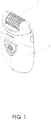
- Fig. 1 depicts an epilating device 1 comprising an epilating head 2 and driving unit 3.
- the epilating head 2 is adapted to be attached to the driving unit 3 and to receive at least one of rotational movement or torque from it.
- the driving unit 3 comprises two buttons for detaching the epilating head 2 and a controlling circuitry.
- the buttons are placed on the narrow sides of the driving unit 3. By pushing both buttons and shifting upwards the epilating head 2, the head can be detached.
- the controlling circuitry can be used to start, stop, and change a torque or speed of rotation of the driving unit and hence the epilating head 2.
- the epilating head comprises a substantially curved cylinder, arranged to epilate or tweeze user's hairs.
- the cylinder is situated on the upper part of the epilating head 2.
- a plastic cover is used to prevent unwanted user's contact with moving gears covers the left and right sides of the cylinder.
- the central part of the cylinder is adapted to be open and exposed to a user. This part is a working part arranged to depilate/epilate hairs by contact with user's skin and interaction with the hairs.
- Fig. 2 depicts an epilating head 2 and a driving unit 3 without their plastic covers, exposing their internal structure.
- the epilating head 2 comprises a gear assembly, arranged to transfer torque or a rotational movement from a motor 4 to the epilating head 2.
- One or more batteries 9 can drive the motor 4.
- the motor 4 meshes with the gear assembly by a motor gear 5, which in turn drive two small gears meshed with a face gear 6.
- the face gear 6 transfers torque and a rotational movement to an idler gear 7, which in turn meshes with a head gear 8.
- the head gear 8 is firmly attached to an epilating cylinder, setting it in motion.
- Fig. 3 depicts a more detailed view of an epilating head 2.
- An epilating cylinder is driven by a head gear 8, which is meshed with a gear assembly with an idler gear 7 that can be seen in the figure.
- the head gear 8 is attached to the side of the cylinder, where the head gear 8 and cylinder together are adapted to be fixed on a curved axle (not shown), which is connected to mobile back parts 12.
- the mobile back parts 12 are arranged to be a part of a head base 10. They are placed on the side edges of the head base 10.
- the head base 10 comprises one or more, preferably four latches situated on the bottom side of the head base 10.
- the epilating cylinder is made in the form of a group or set of pincer or tweezer assemblies 13 that are packed and held on a curved axle (not shown).
- a biasing spring 11, e.g., made of metal, or a frame is adapted to hold the group of the pincer assemblies 13. Instead also a rigid structure to hold the elements in place can be used.
- a single pincer assembly 13 is depicted. It comprises a hub unit 20, a first disc 21, a second disc 22, and a third disc 23.
- Each pincer assembly 13 is adapted to have six epilating tweezers, uniformly placed along the circumference of the cylinder but all or some of them having a different position to the axis of rotation.
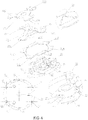
- Fig. 4 depicts a more detailed view of one pincer assembly 13 comprising a hub unit 20, the first disc 21, the second disc 22, and the third disc 23.
- the third disc 23 comprises pincers 23A, 23B, 23C, anvil or a second pincer 23B being placed on a medium or same level regarding the level of a middle section of the third part, a first pincer 23A on a level that is lower in the image shown or displaced to one side of the middle section of the third pincer 23, and a third pincer 23C on a level that is higher in the image shown or displaced to another side of the middle section of the third pincer 23.
- the second disc 22 is shaped similarly with a second pincer 22B on the same level, a first pincer 22A on a lower level and a third pincer 22C on a higher level than the respective middle section.
- the respective pincers 23A, 23B, 23C, 22A, 22B, 22C together provide a part of tweezers different in axial displacement to each other.
- the first disc comprises six anvils or pincers 21A, 21B, 21C, 21D, 21E, 21F, which are displaced or axially offset according to the corresponding pincer of the second or third discs, respectively.
- the hub unit 20 is adapted to regulate the distance of the first to third discs with respect to each other by controlling at least one of their axial displacements or their tilting on the axle.
- the displacement of the third disc 23 is achieved by means of three upper ball-shaped surfaces 28, which are placed on the top of upper ball-shaped surface supports 26. Also, the supports 26 prevent the second disc 22 from rotation, going through three slots 25 for the upper ball-shaped surface supports.
- the elevation of the slot unit 22 is achieved by means of three lower convex or ball-shaped surfaces 27.
- the hub unit 20 comprises topography with protrusions and indentations placed on the side of the hub unit 20 that keep the first disc 21 in the working position and prevent it from unwanted rotation. Moreover, the hub unit 20 comprises three protrusions 30 that engage a neighboring pack of hub unit and first to thirds discs in order to convey the rotational movement and torque. The protrusions 30 are formed at the base thereof additionally in order to prevent the third disc 23 from unwanted rotation. However, the rotation of the assembly comprising the hub unit 20 and the first to third discs 21 to 23 around the axle 36 is allowed.
- the enlarged view in Fig. 4 shown in the lower right part shows the different convex elements 27 and 28 that are positioned to support the respective discs accordingly.
- the protrusion 28 is located on a protrusion 26 that is configured to engage the respective cut-outs or recesses 25 in the center hole of the second disc 22 in order to allow a positive engagement of the second disc 22.
- the bottom view of the hub unit 20 is depicted in the left bottom corner.
- the protrusions 30 can be inserted into three cavities or recesses 31 of the next hub unit 20 to form a respective assembly.
- the hub unit 20 comprises six pressing protrusions 32, adapted to squeeze the pincer assembly 13 from the top when it is desired to activate the tweezers.
- Fig. 5 depicts an assembled single pincer assembly 13.
- the view from the top of a pincer assembly 13 can be seen.
- the view from the side of the pincer assembly 13 can be seen.
- the cross-section across line B-B is going through the centers of two assembled tweezers, two pressing protrusions 32, upper ball-shaped surface of protrusion 28, the center of the assembly, and lower ball-shaped surface 27.
- the cross-section can be seen in the second row of drawings in a tilted manner.
- the left tweezer which is squeezed, comprises a pincer 22C of the second disc 22 and a pincer 21E of the first disc 21.
- the right tweezer which is shown in an opened condition, comprises a lower pincer 21B of the first disc 21 and an upper pincer of the third disc 23.
- protrusions 30 protrude beyond the rest of the pack of elements in order to engage the neighboring pack.
- the cross-section D-D is going through the centers of two assembled tweezers, two pressing protrusions 32, upper ball-shaped surface 28, the center of the assembly, and lower ball-shaped surface 27.
- the respective cross-section is depicted to the right in the first row of drawings.
- the upper tweezer which is shown open for releasing hair, is composed of the pincer 22B and pincer 21A.
- the tweezer below which is shown in the closed position, is composed of the pincers 23C and 21D.
- the respective support and engagement of the first to the third discs can be further derived from these figures.
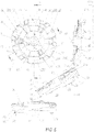
- Fig. 6 depicts an epilating head 2 without covers at the end.
- a front view is presented on the top of the page and the top view in the center.
- the two arrows each marked with a P show that a force or pressure is applied from the side onto the epilating head.
- this could be realized by a dense packing of the elements in the head or even a biasing arrangement by metallic side supporting structures acting similar to springs.
- the cross-section A-A is going through the center of an epilating cylinder.
- the respective cross-section can be seen on the bottom of the page.
- the epilating cylinder is assembled by a number of hub units and discs or pincer assemblies.
- the right part of the cylinder is shown without hub units 20, providing a detailed view of the internal structure, particularly of the arrangement of the discs.
- the group of pincer assemblies is arranged on a curved axle 36.
- the ends of the curved axle 36 are fixed in a head base 10 and mobile back part 12.
- the curved axle 36 is adapted to be fixed but the group of pincer assemblies 13 to rotate around the curved axle 36 as a whole driven by a head gear 8 which is meshed with a gear assembly 7.
- the spring 11 which made in the form of a metal frame, applies a squeezing force to both the head base 10 and mobile back part 12 in the P directions. Because of curvature, the upper part of the group of pincer assemblies exercises a maximal squeezing force but the opposite no pressure or less. Hence, the tweezers on the top site are squeezed and ones on the opposite site are opened or released. Therefore, the rotating group of pincer assemblies cause the trapping of hair, the epilating of user's hairs and the release thereof.
- Fig. 7 depicts an assembled single pincer assembly.
- the cross-section B-B has been made through the centers of two assembled tweezers being shown on top of the figure and the two pressing protrusions 32 and lower ball-shaped surface 27.
- the imaginary cut can be seen at the bottom left corner.
- the left tweezer is closed and/or squeezed, the right tweezer is opened and/or released.
- the cross-section is passing along a slot unit 22 showing its cutting.
- the cross-section C-C is going through the centers of two assembled tweezers, two pressing protrusions 32, and upper ball-shaped surface 28.
- the cross-section can be seen at the bottom right corner of Fig. 7 .
- the left tweezer is shown in the squeezed state, the right tweezer in the released state.
- Line 33 is drawn between two adjacent upper ball-shaped surfaces 28, showing two-point bending line of a top unit 23.
- the line is situated outside the center area occupied by a curved axle 36, hence its friction is reduced during the squeezing/releasing process.
- the imaginary line 34 is drawn between two adjacent lower ball-shaped surfaces 27, showing two-point bending line of a slot unit 22.
- the line is situated outside the center area occupied by the curved axle 36, hence its friction is reduced during the squeezing/releasing process.
- Fig. 8 depicts three adjacent pincer sets or assemblies 13 strung on a curved axle 36 and shown at the top left corner.
- the cross-section A-A is going through the curved axle 36.
- the cross-section can be seen at the bottom of the page, where the top tweezers are squeezed and the bottom ones released because of curvature of the curved axle 36 and squeezing force of a spring 11 (not shown).
- the cross-section B-B in Fig 8 shows the function of a generating protrusion 30 inserted into a recess or cavity 31.
- the generating protrusion 30 and cavity 31 still engage even in the status when neighboring sets are spaced from each other. In the opposite side they engage more clearly or deeply.
- the elevation of the generating protrusion 31 and the curvature of the curved axle 36 are designed to be high and big enough to allow the pincer assemblies 13 be substantially tightly squeezed on the top side and released on the bottom side.
- Fig. 9 shows perspective views of an assembly of elements 20 to 23 according to another embodiment of the invention.
- the hub unit 20 also takes the role of a counter element with counterparts 20A to 20F.
- These counterparts 20A to 20F cooperate with the pincers 22A to 22C as well as 23A to 23C to form tweezers.
- a third disc is not present but replaced by respective shapes of the hub unit's counterparts.
Description
- The invention is directed to an epilating head for an epilating device especially to an epilating head comprising a group of pincer assemblies.
- Depilating devices use one of two methods for removing hair. In one method, the hair is cut, leaving the roots intact beneath the skin surface. In the other method, hair is removed by pulling it out from its roots.
- There are several mechanisms for removing hair. Disc mechanisms are often used. In general, these mechanisms include discs and associated pincer-like elements. When two pincer-like elements are brought close together, hair is trapped between them. The discs, which rotate and produce a torque, then uproot the hair trapped between their associated pincers. The pincer-like elements and their associated discs move in unison and all pincer-like elements within a fixed distance move close to their adjacent pincer-like elements synchronously. The forces required in such mechanisms are multiples of the number of pincers. In some of these depilatory devices, the disc mechanisms have cylindrical shapes. Other depilating devices which use disc mechanisms employ a large spring with bearings connected to its ends. In such devices, the spring presses on the bearings producing a constant force that acts identically over all the discs and their associated pincer-like elements. The magnitude of the force is the same throughout the entire mechanism. The forces required in such mechanisms are relatively small and the energy required is not great.
- Several of the proposed disc hair removal systems involve the use of tilted discs which come together at a point to grasp one or more strands of hair. Other disc mechanisms involve the use of cams to alternately bring the discs together and apart, thereby trapping strands of hair.
- Various disc mechanisms are discussed in publication number
US 2012/0035621 and inUS Pat. Nos. 4,935,024 to Dolev ;5,057,115 to Dolev ;5,190,559 to Gabion et al. ;5,797,925 to Heintke ;5,857,903 to Ramspeck et al. ;5,312,419 to Garenfeld et al. ;5,196,021 to Kabla ;5,281,233 to Dolev and5,462,557 to Jordan et al. - A depilatory device using a disc mechanism is subject to several constraints. The pincer-like elements associated with each disc must close quickly. The pressure exerted by each contacting pair of pincers must be neither too great nor too little. In the former case, the hair would be cut, while in the latter case, the hair would slide through without being pulled out at its roots. Typically, all the pincers associated with a row of discs must contact their adjacent pincers simultaneously. Lastly, the contacting mechanism must be simple, operate reliably over time, and be easy to maintain.
- Presently, there is a need for an epilator and/or depilatory device that is easy and inexpensive to assemble and to maintain and which can uproot a greater number of hairs over a larger area than is possible using prior art devices. In addition, there is also an ongoing need for a depilating device that reduces discomfort associated with hair removal.
- In
WO 2009/010815 A1 an epilator is described comprising a head for trapping hair for removal. The head comprises a rotating body that has as an axis of rotation and is adapted to be rotated by a motor. At least one pair of pincers is arranged at or in the rotating body. The pair of pincers is able to rotate in accordance with the rotation of the rotating body. At least their outermost ends are adapted to move towards each other and away from each other depending on the location of the rotating body. According to an aspect, at least one intermediate member is provided which is arranged such that it is at least linearly moveable between the outermost ends of the pincers. The pair of pincers only extends on one side of the axis of rotation. One spring is located between the pair of pincers and is arranged to bias the pincers either away from each other or towards each other. At least one actuator is provided for the pair of pincers which can be supported to move along or parallel to the axis of rotation and engages a first pincer adjacent an end thereof being distal to the axis of rotation and a second pincer at or adjacent an end thereof being proximal to the axis of rotation. - The epilating device according to
EP 0 950 365 includes a single housing that is shaped to be grasped by the hand of a user and which includes a drive source. The housing can carry a first epilation module provided at its top with a first plucking head that is driven by the drive source to effect the plucking of the body hairs. The first plucking head has a length defining there along a first epilation zone. Also provided is a second epilation module to be carried on the housing that is provided at its top with a second plucking head that is driven commonly by the drive source to effect plucking of the body hairs. The second plucking head has a length defining there along a second epilation zone. -
EP 1 405 701 B1 -
WO 2005/063076 is directed to a depilator assembly for trapping hair for removal. The assembly includes a symmetric disc formed of two lobes and two pincers. At least two pressure-transferring protrusions and at least one rotation transferring protrusion are formed and positioned on a first face of said disc. Further rat least two pressure-transferring protrusions and at least two spacer elements are formed and positioned on a second face of said disc. The spacer elements being operative to prevent the accumulation of debris between adjacent discs and to allow for periodic tilting of the discs when pressure is provided to the depilator assembly. The second face of the disc further has formed therein at least one recess configured to accommodate said at least one rotation-transferring protrusions of a similar disc of an adjacent depilator assembly in force transferring engagement, such that, in response to a rotational force applied to said assembly at least one rotation-transferring protrusion is operative to transfer rotation to said adjacent assembly. -
WO 2015/121851 relates to an epilator comprising a pair of corresponding and separable epilator heads for trapping hair for removal. Each head has an exposed portion for allowing at least one or more parts of each head to get in touch with a user's skin. Each head has a rotating body having an axis of rotation and being adapted to be rotated by a driving unit, wherein the rotating body is adapted to trap the hair for removal at the exposed portion, and wherein the axis of the rotating body is essentially concave relative to the exposed portion of each head. - All the above-mentioned documents are herewith incorporated by reference.
- The present invention is directed to an epilating head according to
claim 1, a pincer assembly according toclaim 14 and a method according to claim 15. - The present invention is directed to an epilating head for an epilating device. It can comprise the following features or any subgroup thereof. There is at least a first disc with at least two first disc pincers. The first disc can be configured to be rotatable around an axle of rotation or around an axis of rotation. In the first case the axle does not rotate and the disc can rotate around the axle or can be arranged on an element rotating together with the disc around the axle. In the second case the axle can rotate itself. In the further case it is not curved, it could be made of segments or an elastic material in order to allow it to rotate. Then the disc can be arranged directly on the axle and rotate with axle.
- Thus, also the pincers can rotate around the axle of rotation. There can be arranged at least a counter element or a second disc with at least two counterparts or second disc pincers. Also the counter element or second disc can be configured to be rotatable around the axle or the axis, as described before.
- The term counter element or disc is not limited to a flat piece of material but can have a considerable thickness. Moreover, it can have any topography and not just two planes with protrusions, e.g. the protrusions being cold drawn or formed in a body.
- The first and the counter element or second discs can be configured so that a first pair is composed of one of the first disc pincers and of one of the counterparts or second disc pincer to form a first tweezer. Thus, neighboring pincers of different discs can form a tweezer. A second pair composed of one of the first disc pincers and one of the further counterparts or second disc pincer can form a second tweezer.
- The pincers formed at the discs can be provided in any way, either by providing a flat material, punch it and then deform the parts thereof into different directions or planes.
- The first and second tweezers can each be brought in an open condition over at least a first section of rotation around the axle or axis. The first and second tweezers each can be in a closed condition over a second section of rotation around the axle or axis. The opening of the tweezers is intended to happen when hair of a user is either brought into the tweezers or released from the tweezers once the hairs are plugged out. The closing is intended to primarily take place during the gripping of hair and the remaining in the closed position is intended to primarily take place when plugging or epilating/depilating of hair.
- As the tweezers of cooperating discs are positioned at different locations at the respective discs the first and second tweezers can open and close at different times although they can open at similar or neighboring locations during rotation of the discs. The first tweezer and the second tweezer are at least one of axially offset, their envelopes of rotation are neighboring or their envelopes of rotation are side by side. Thus, they are offset and/or their envelopes of rotation do not coincide but are arranged in an axial neighborhood or side by side. This can ensure that the body or skin of a user will be depilated easier and more effectively as the device will treat a surface of the body or skin more equally and completely.
- The first disc pincers can be formed by first disc protrusions radially extending at least in part from the first disc. The second disc pincers are formed by second disc protrusions radially extending at least in part from the second disc. Neighboring first disc pincers and/or neighboring second disc pincers can be axially offset to each other. This can ensure that the tweezers formed by the pincers become active not at the same location of the skin but at neighboring locations. Thus the surface of a user's skin is more equally and completely treated over a width of the epilating head without making it necessary for the user to considerably move the device during use.
- The epilating device can also comprise a third disc with at least two third disc pincers. Also a further disc could be provided. Anyhow, the third disc can be rotatable around the axis or axle of rotation. In this case the first and the third discs can be configured that a third pair composed of one of the first disc pincers and one of the third disc pincers form a third tweezer and a fourth pair composed of one of the first disc pincers and one of the third disc pincers form a fourth tweezer.
- The third and fourth tweezers can be in an open condition over at least a first section of rotation around the axis or axle. The third and fourth tweezers can each or in groups be in a closed condition over a second section of rotation around the axis or axle. The third tweezer and the fourth tweezer can be at least one of axially offset, their envelopes of rotation are neighboring or their envelopes of rotation are side by side, as already further mentioned before.
- The first disc can have from 4 to 8 pincers and each of the second disc and the third disc can have from 2 to 4 pincers so that from 4 to 8 tweezers are formed.
- The first disc can have 6 pincers and each of the second disc and the third disc can have from 3 pincers so that 6 tweezers are formed.
- The epilating head according to the present invention can comprise 4 to 12 sets of first, second and third discs, preferably 6-10 sets of first, second and third discs, more preferably 8 sets of first, second and third discs. Any other number of sets can also be realized. These numbers of sets of discs can ensure a harmonious and equal treatment of the user's skin by a head.
- Moreover, a head drum can be formed by a plurality of hub units each supporting a set of discs rotating around the axis or axle.
- At least one of the second disc and the third disc can have extensions formed at the pincers extending outwardly in the direction of rotation and adapted to assist in guiding hair into the tweezers, the extensions being inclined between 10-40° with respect to the plane of the pincers, preferably between 25-35°.
- The axis or axle of rotation is formed concave with respect to a side of use. It can thus better be adapted to the generally skin of a user that is generally convexly shaped. The tweezers can be adapted to be in an open condition over the first section of circumference of rotation around the axis or axle and in a closed condition over the second section of circumference of rotation around the axis or axle.
- Each of the first disc, the second disc and/or the third disc have an inner opening being adapted to support a coaxial support of the first disc, the second disc and/or the third disc. The opening can be round or can have any shape allowing a positively locking rotation with other elements or the axle. These can be slots, specific shapes of the holes etc. allowing for the engagement of correspondingly shaped elements.
- At least two hub units each can be adapted to be supported on the axis or axle and to rotate on the axis or axle. Further the hub unit can support the first disc, the second disc and/or the third disc, so that they rotate together with the respective hub unit. Each hub unit can further be configured to bring the tweezers each in an open condition over at least a first section of circumference of rotation and in a closed condition over at least a second section of circumference of rotation around the axis or axle. This can cause a periodic movement, deformation and preferably tilting of one, more than one or all of the discs.
- The axis or axle can be formed concave with respect to a side of use. At least two sets of hub units can be arranged on the axis or axle. In view of the concave shape of the axis or axle the hub units can each being configured to cause the tweezers in an open condition over at least a first section of circumference of rotation and in a closed condition over at least a second section of circumference of rotation around the axis or axle, preferably in or close to the side of use.
- A plurality of hub units can be arranged side by side on the axis or axle to form a rotating head drum. The hub units can have pressure-transferring protrusions on the side opposite to the side of the discs transferring pressure to the discs of the neighboring hub unit. This can further assist the tweezers of the neighboring hub unit to be in an open condition over the first section of circumference of rotation around the axis or axle and in a closed condition over the second section of circumference of rotation around the axis or axle.
- The head drum can further comprise at one end a second hub unit driving the head drum and forming an end section of a head drum with pressure-transferring protrusions transferring pressure onto a set of discs of the neighboring hub unit. At the other end a third hub unit can form the opposite end section and comprising a set of discs.
- At least two pressure-transferring protrusions can be formed and positioned on a side of the hub unit. The first to the third discs can be adapted to be positioned on one side of the hub unit. It can be further adapted for periodic tilting where in a first section of 360° rotational movement, the pressure-transferring protrusions from a similar adjacent pincer assembly are configured to press on at least one of the discs thereby to cause the discs to contact each other at their pincer surfaces trapping hair there between. In a second section, the contact between the pincer surfaces is adapted to be ceased releasing the trapped hair.
- The axis or axle can be formed as an arcuate axis or axle. The hub unit can comprise at least one rotation-transferring protrusion formed and positioned on one side. Further, at least one recess can be adapted to accommodate a rotation-transferring protrusion of the similar adjacent pincer assembly for transferring rotational momentum or movement and stacking the similar adjacent pincer assembly to the hub unit.
- The hub unit comprises at least three lower convex surfaces and at least three upper convex surfaces on the side of the hub unit hosting the discs. It can be adapted to elevate the second disc and the third disc from the one side of the hub unit respectively and result in a desired separation of the discs. It can further allow the periodic tilting of the units under the influence of the pressure transferring protrusions.
- The at least three lower convex surfaces can be three lower convex surfaces which are positioned 120° apart and/or wherein the at least three upper convex surfaces can be three upper convex surfaces which are positioned 120° apart.
- The upper convex surfaces can be adapted to be inserted through three slots that are comprised in the second disc.
- The at least two first pincers can be six first pincers which are positioned 60° apart. Three second pincers can be positioned 120° apart. The at least two third pincers can be three third pincers which are positioned 120° apart. This can also ensure a harmonious but nevertheless effective depilation of hair.
- Six tweezers can be a combination of one of the first pincers and one of the second pincers or a combination of one of the first pincers and one of the third pincers. All of the tweezers are axially offset from each other during the rotation of the pincer assembly around the arcuate axis or axle.
- A group of pincer assemblies can be mounted on the axis or axle and can be adapted to rotate around the axis or axle.
- The axis or axle can be an arcuate axis or axle that is configured to be fixed to a head base and a back base.
- The group of pincer assemblies can be adapted to be situated between a head gear and a backside unit that can be adapted to transfer an applied force to the group of pincer assemblies. The head gear can be further adapted to receive a rotational momentum or movement from an idler gear and transfer it to the group of pincer assemblies.
- The epilating head can further comprise a spring that is adapted to provide pressure to the group of pincer assemblies. A substantial part of the pressure can be applied to the most curved edge of the group of pincer assemblies.
- Further a driving unit can be provided. The driving unit can comprise a gear assembly, motor and/or a power source unit. The power source unit can comprise one or more batteries configured to supply the motor with power.
- The gear assembly can comprise a motor gear receiving a rotational momentum from the motor and/or a face gear transferring the rotational momentum to an idler gear via intermediate gears.
- The present invention is also directed to a method for operating an epilating head, especially an epilating head according to any of the relevant preceding claims. Thus, all features described before and specified in the claims with respect to a device are also embraced by the invention in terms of method steps, even without being explicitly mentioned.
- The drawings, described below, are for illustration purposes only. The drawings are not intended to limit the scope of the present teaching in any way.
-
Fig. 1 exemplifies a perspective view of an epilating device according to an embodiment of the invention; -
Fig. 2 exemplifies a perspective view of a part of an epilating head and a drive with gear according to an embodiment of the invention; -
Fig. 3 exemplifies a perspective view onto an epilating head and a part thereof according to an embodiment of the invention; -
Fig. 4 exemplifies a perspective view onto a part of an epilating head and a top view and enlarged view of parts thereof according to an embodiment of the invention; -
Fig. 5 exemplifies a top view and cross-sections of a part of an epilating head according to an embodiment of the invention; -
Fig. 6 exemplifies different views onto an epilating head according to an embodiment of the invention; -
Fig. 7 exemplifies a top view and cross-sections of a part of an epilating head according to an embodiment of the invention; -
Fig. 8 exemplifies a side view onto parts of an epilating head and cross-sections thereof according to an embodiment of the invention; and -
Fig. 9 shows another embodiment of a subset of elements of an epilating head according to the present invention. -
Fig. 1 depicts anepilating device 1 comprising anepilating head 2 and drivingunit 3. Theepilating head 2 is adapted to be attached to thedriving unit 3 and to receive at least one of rotational movement or torque from it. - Also, the driving
unit 3 comprises two buttons for detaching theepilating head 2 and a controlling circuitry. The buttons are placed on the narrow sides of thedriving unit 3. By pushing both buttons and shifting upwards theepilating head 2, the head can be detached. - The controlling circuitry can be used to start, stop, and change a torque or speed of rotation of the driving unit and hence the
epilating head 2. - The epilating head comprises a substantially curved cylinder, arranged to epilate or tweeze user's hairs. The cylinder is situated on the upper part of the epilating
head 2. A plastic cover is used to prevent unwanted user's contact with moving gears covers the left and right sides of the cylinder. The central part of the cylinder is adapted to be open and exposed to a user. This part is a working part arranged to depilate/epilate hairs by contact with user's skin and interaction with the hairs. -
Fig. 2 depicts anepilating head 2 and adriving unit 3 without their plastic covers, exposing their internal structure. Theepilating head 2 comprises a gear assembly, arranged to transfer torque or a rotational movement from a motor 4 to theepilating head 2. One ormore batteries 9 can drive the motor 4. Also, the motor 4 meshes with the gear assembly by amotor gear 5, which in turn drive two small gears meshed with aface gear 6. Theface gear 6 transfers torque and a rotational movement to anidler gear 7, which in turn meshes with ahead gear 8. Thehead gear 8 is firmly attached to an epilating cylinder, setting it in motion. -
Fig. 3 depicts a more detailed view of an epilatinghead 2. An epilating cylinder is driven by ahead gear 8, which is meshed with a gear assembly with anidler gear 7 that can be seen in the figure. - The
head gear 8 is attached to the side of the cylinder, where thehead gear 8 and cylinder together are adapted to be fixed on a curved axle (not shown), which is connected tomobile back parts 12. Themobile back parts 12 are arranged to be a part of ahead base 10. They are placed on the side edges of thehead base 10. Also, thehead base 10 comprises one or more, preferably four latches situated on the bottom side of thehead base 10. - The epilating cylinder is made in the form of a group or set of pincer or
tweezer assemblies 13 that are packed and held on a curved axle (not shown). A biasingspring 11, e.g., made of metal, or a frame is adapted to hold the group of thepincer assemblies 13. Instead also a rigid structure to hold the elements in place can be used. - On the bottom of the figure, a
single pincer assembly 13 is depicted. It comprises ahub unit 20, afirst disc 21, asecond disc 22, and athird disc 23. Eachpincer assembly 13 is adapted to have six epilating tweezers, uniformly placed along the circumference of the cylinder but all or some of them having a different position to the axis of rotation. -
Fig. 4 depicts a more detailed view of onepincer assembly 13 comprising ahub unit 20, thefirst disc 21, thesecond disc 22, and thethird disc 23. - The
third disc 23 comprisespincers second pincer 23B being placed on a medium or same level regarding the level of a middle section of the third part, afirst pincer 23A on a level that is lower in the image shown or displaced to one side of the middle section of thethird pincer 23, and athird pincer 23C on a level that is higher in the image shown or displaced to another side of the middle section of thethird pincer 23. Thesecond disc 22 is shaped similarly with asecond pincer 22B on the same level, afirst pincer 22A on a lower level and athird pincer 22C on a higher level than the respective middle section. Therespective pincers - The first disc comprises six anvils or
pincers - The
hub unit 20 is adapted to regulate the distance of the first to third discs with respect to each other by controlling at least one of their axial displacements or their tilting on the axle. - The displacement of the
third disc 23 is achieved by means of three upper ball-shapedsurfaces 28, which are placed on the top of upper ball-shaped surface supports 26. Also, thesupports 26 prevent thesecond disc 22 from rotation, going through threeslots 25 for the upper ball-shaped surface supports. - The elevation of the
slot unit 22 is achieved by means of three lower convex or ball-shapedsurfaces 27. - The
hub unit 20 comprises topography with protrusions and indentations placed on the side of thehub unit 20 that keep thefirst disc 21 in the working position and prevent it from unwanted rotation. Moreover, thehub unit 20 comprises threeprotrusions 30 that engage a neighboring pack of hub unit and first to thirds discs in order to convey the rotational movement and torque. Theprotrusions 30 are formed at the base thereof additionally in order to prevent thethird disc 23 from unwanted rotation. However, the rotation of the assembly comprising thehub unit 20 and the first tothird discs 21 to 23 around theaxle 36 is allowed. - The enlarged view in
Fig. 4 shown in the lower right part shows the differentconvex elements protrusion 28 is located on aprotrusion 26 that is configured to engage the respective cut-outs or recesses 25 in the center hole of thesecond disc 22 in order to allow a positive engagement of thesecond disc 22. - The bottom view of the
hub unit 20 is depicted in the left bottom corner. Theprotrusions 30 can be inserted into three cavities or recesses 31 of thenext hub unit 20 to form a respective assembly. Also, thehub unit 20 comprises sixpressing protrusions 32, adapted to squeeze thepincer assembly 13 from the top when it is desired to activate the tweezers. -
Fig. 5 depicts an assembledsingle pincer assembly 13. In the left top corner, the view from the top of apincer assembly 13 can be seen. In the left bottom corner, the view from the side of thepincer assembly 13 can be seen. - The cross-section across line B-B is going through the centers of two assembled tweezers, two pressing
protrusions 32, upper ball-shaped surface ofprotrusion 28, the center of the assembly, and lower ball-shapedsurface 27. The cross-section can be seen in the second row of drawings in a tilted manner. The left tweezer, which is squeezed, comprises apincer 22C of thesecond disc 22 and apincer 21E of thefirst disc 21. The right tweezer, which is shown in an opened condition, comprises alower pincer 21B of thefirst disc 21 and an upper pincer of thethird disc 23. - It is further apparent that the
protrusions 30 protrude beyond the rest of the pack of elements in order to engage the neighboring pack. - The cross-section D-D is going through the centers of two assembled tweezers, two pressing
protrusions 32, upper ball-shapedsurface 28, the center of the assembly, and lower ball-shapedsurface 27. The respective cross-section is depicted to the right in the first row of drawings. The upper tweezer, which is shown open for releasing hair, is composed of thepincer 22B and pincer 21A. The tweezer below which is shown in the closed position, is composed of thepincers -
Fig. 6 depicts anepilating head 2 without covers at the end. A front view is presented on the top of the page and the top view in the center. In the top view the two arrows each marked with a P show that a force or pressure is applied from the side onto the epilating head. As mentioned before, this could be realized by a dense packing of the elements in the head or even a biasing arrangement by metallic side supporting structures acting similar to springs. - The cross-section A-A is going through the center of an epilating cylinder. The respective cross-section can be seen on the bottom of the page.
- The epilating cylinder is assembled by a number of hub units and discs or pincer assemblies. The right part of the cylinder is shown without
hub units 20, providing a detailed view of the internal structure, particularly of the arrangement of the discs. - The group of pincer assemblies is arranged on a
curved axle 36. The ends of thecurved axle 36 are fixed in ahead base 10 and mobileback part 12. Thecurved axle 36 is adapted to be fixed but the group ofpincer assemblies 13 to rotate around thecurved axle 36 as a whole driven by ahead gear 8 which is meshed with agear assembly 7. - The
spring 11, which made in the form of a metal frame, applies a squeezing force to both thehead base 10 and mobileback part 12 in the P directions. Because of curvature, the upper part of the group of pincer assemblies exercises a maximal squeezing force but the opposite no pressure or less. Hence, the tweezers on the top site are squeezed and ones on the opposite site are opened or released. Therefore, the rotating group of pincer assemblies cause the trapping of hair, the epilating of user's hairs and the release thereof. -
Fig. 7 depicts an assembled single pincer assembly. The cross-section B-B has been made through the centers of two assembled tweezers being shown on top of the figure and the twopressing protrusions 32 and lower ball-shapedsurface 27. The imaginary cut can be seen at the bottom left corner. The left tweezer is closed and/or squeezed, the right tweezer is opened and/or released. The cross-section is passing along aslot unit 22 showing its cutting. - The cross-section C-C is going through the centers of two assembled tweezers, two pressing
protrusions 32, and upper ball-shapedsurface 28. The cross-section can be seen at the bottom right corner ofFig. 7 . The left tweezer is shown in the squeezed state, the right tweezer in the released state. -
Line 33 is drawn between two adjacent upper ball-shapedsurfaces 28, showing two-point bending line of atop unit 23. The line is situated outside the center area occupied by acurved axle 36, hence its friction is reduced during the squeezing/releasing process. - The
imaginary line 34 is drawn between two adjacent lower ball-shapedsurfaces 27, showing two-point bending line of aslot unit 22. The line is situated outside the center area occupied by thecurved axle 36, hence its friction is reduced during the squeezing/releasing process. -
Fig. 8 depicts three adjacent pincer sets orassemblies 13 strung on acurved axle 36 and shown at the top left corner. - The cross-section A-A is going through the
curved axle 36. The cross-section can be seen at the bottom of the page, where the top tweezers are squeezed and the bottom ones released because of curvature of thecurved axle 36 and squeezing force of a spring 11 (not shown). - The cross-section B-B in
Fig 8 shows the function of a generatingprotrusion 30 inserted into a recess orcavity 31. As it can be seen, the generatingprotrusion 30 andcavity 31 still engage even in the status when neighboring sets are spaced from each other. In the opposite side they engage more clearly or deeply. The elevation of the generatingprotrusion 31 and the curvature of thecurved axle 36 are designed to be high and big enough to allow thepincer assemblies 13 be substantially tightly squeezed on the top side and released on the bottom side. -
Fig. 9 shows perspective views of an assembly ofelements 20 to 23 according to another embodiment of the invention. In this embodiment thehub unit 20 also takes the role of a counter element withcounterparts 20A to 20F. Thesecounterparts 20A to 20F cooperate with thepincers 22A to 22C as well as 23A to 23C to form tweezers. In such an assembly a third disc is not present but replaced by respective shapes of the hub unit's counterparts.
Claims (15)
- An epilating head for an epilating device comprising:a. at least a first disc (21) with at least two first disc pincers (21A; 21C; 21E) the first disc being rotatable around an axis or axle (36) of rotation;b. at least a counter element (20; 22) with at least two counterparts (20A-F;22A-C), the counter element (20; 22) being rotatable around the axis or axle (36);c. the first disc (21) and the counter element (20; 22) being configured that a first pair of tweezers (21A, 20A; 21A, 22A) is composed of one of the first disc pincers (21A) and one of the counterparts (20A-F; 22A-C) and a second tweezer (21C, 20C; 21C, 22C) is composed of another one of the first disc pincers (21C) and another one of the counterparts (20A-F; 22A-C);i. the first and second tweezers (21A, 22A; 21C, 22C) each being in an open condition over at least a first section of rotation around the axis or axle (36) andii. the first and second tweezers (21A, 22A; 21C, 22C) each being in a closed condition over a second section of rotation around the axis or axle (36);d. wherein the first tweezer (21A, 22A) and the second tweezer (21C, 22C) are axially offset or their envelopes of rotation are neighboring or side by side.
- An epilating head according to claim 1, wherein the counter element (22) is a second disc (22) and the counterparts (22A-C) are second disc pincers (22A, 22B, 22C) the first and the second discs (21, 22) being configured that a first pair composed of one of the first disc pincers (21A) and one of the second disc pincer (22A) form a first tweezer (21A, 22A) and a second pair composed of one of the second disc pincers (21C) and one of the second disc pincer (21C) form a second tweezer (21C, 22C).
- Epilating head according to claim 2 wherein the first disc pincers (21A; 21C; 21E) are formed by first disc protrusions (21A; 21C; 21E) radially extending at least in part from the first disc (21) and the second disc pincers (22A, 22B, 22C) are formed by second disc protrusions (22A, 22B, 22C) radially extending at least in part from the second disc (22), and/or wherein neighboring first disc pincers (21A; 21C; 21E) and/or neighboring second disc pincers (22A, 22B, 22C) are at least one of axially offset to each other, their envelopes of rotation are neighboring or side by side.
- Epilating head according to any one of the preceding claims further comprising:a. a third disc (23) with at least two third disc pincers (23A; 23B; 23C), the third disc (23) being rotatable around the axis or axle (36) of rotation;b. the first and the third discs (21, 23) being configured that a third pair composed of one of the first disc pincers (21B) and one of the third disc pincers (23A) form a third tweezer (21B, 23A) and a fourth pair composed of one of the first disc pincers (21F) and one of the third disc pincers (23B) form a fourth tweezer (21F, 23B);i. the third and fourth tweezers (21B, 23A; 21F, 23B) each being in an open condition over at least a first section of rotation around the axis or axle (36) andii. the third and fourth tweezers (21B, 23A; 21F, 23B) each being in a closed condition over a second section of rotation around the axis or axle (36);c. wherein the third tweezer (21B, 23A) and the fourth tweezer (21F, 23B) are axially offset or their envelopes of rotation are neighboring or side by side.
- Epilating head according to any one of the preceding claims and the features of claim 4 wherein the first disc (21) has from 4 to 8 pincers (21A-F) and each of the second disc (22) and the third disc (23) have from 2 to 4 pincers, preferably 3 pincers, so that from 4 to 8 tweezers, preferably 6 tweezers, are formed.
- Epilating head according to any one of the two preceding claims comprising 4 to 12 sets of first, second and third discs (21-23), preferably 6-10 sets of first, second and third discs (21-23), more preferably 8 sets of first, second and third discs (21-23).
- Epilating head according to any one of the preceding claims further comprising a head drum (20, 21-23) being formed by a plurality of hub units (20) each supporting a set of discs (21-23) rotating around the axis or axle (36).
- Epilating head according to any one of the four preceding claims wherein at least one of the second disc (22) and the third disc (23) have extensions formed at the pincers (22AC,23A-C) extending outwardly in the direction of rotation and adapted to assist in guiding hair into the tweezers, the extensions being inclined between 10-40° with respect to the plane of the pincers (22A-C, 23A-C), preferably between 25-35°.
- Epilating head according to any one of the preceding claims wherein the axis or axle (36) is formed concave with respect to a side of use and adapted to assist the tweezers (21A, 22A; 21C, 22C) to be in an open condition over the first section of circumference of rotation around the axis or axle (36) and in a closed condition over the second section of circumference of rotation around the axis or axle (36).
- Epilating head according to any one of the six preceding claims further comprising at least two hub units (20) each adapted to be supported on the axis or axle (36) and to rotate on the axis or axle (36) and to further support the first disc (21), the second disc (22) and the third disc (23), so that they rotate together with the respective hub unit (20), each hub unit (20) further preferably being configured in bringing the tweezers (21AF; 22A-C, 23A-C) each in an open condition over at least a first section of circumference of rotation and in a closed condition over at least a second section of circumference of rotation around the axis or axle (36) by a periodic tilting of one, more than one or all of the discs (21-23).
- Epilating head according to the preceding claim wherein the axis or axle (36) is formed concave with respect to a side of use, at least two sets of hub units (20) being arranged on the axis or axle (36) and in view of the concave shape of the axis or axle (36) the hub units (20) each being configured to cause the tweezers (21A-F; 22A-C, 23A-C) each in an open condition over at least a first section of circumference of rotation and in a closed condition over at least a second section of circumference of rotation around the axis or axle (36), preferably in or close to the side of use.
- Epilating head according to any one of the preceding claims wherein a plurality of hub units (20) are arranged side by side on the axis or axle (36) to form a rotating head drum, the hub units having pressure-transferring protrusions (32) on the side opposite to the side of the discs (21-23) transferring pressure to the discs (21-23) of the neighboring hub unit (20) to further assist the tweezers (21A, 22A; 21C, 22C) of the neighboring hub unit (20) to be in an open condition over the first section of circumference of rotation around the axis or axle (36) and in a closed condition over the second section of circumference of rotation around the axis or axle (36).
- Epilating head according to any one of the eight preceding claims further comprising at least two pressure-transferring protrusions (32) formed and positioned on a side (20B) of the hub unit (20) and/or wherein the first to the third discs (20-23) are adapted to be positioned on one side of the hub unit (20) and adapted for periodic tilting where in a first section of 360° rotational movement, the pressure-transferring protrusions (32) from a similar adjacent pincer assembly (13) are configured to press on at least one of the discs (21, 22, 23) thereby to cause the discs (21, 22, 23) to contact each other at their pincer surfaces trapping hair there between and where in a second section, the contact between the pincer surfaces is adapted to be ceased releasing the trapped hair.
- The pincer assembly (13) according to any of the nine preceding claims wherein the hub unit (20) comprises at least three lower convex surfaces (27) and at least three upper convex surfaces (28) on the side of the hub unit (20) hosting the discs (21-23) adapted to elevate the second disc (22) and the third disc (23) from the one side of the hub unit (20) respectively cause separation (120) between the discs (21, 22, 23) and allowing the periodic tilting of the units (22, 23) under the influence of the pressure transferring protrusions (32).
- A method for operating an epilating head, comprising the steps of:a. providing at least a first disc (21) with at least two first disc pincers (21A;21C; 21E), the first disc rotating around an axis or axle (36) of rotation;b. providing at least a counter element (20; 22) with at least two counterparts (20A-F; 22A-C), the counter element rotating around the axis or axle (36);c. configuring the first disc (21) and the counter element (20; 22) to form a first pair of tweezers (21A, 20A; 21A, 22A) that is composed of one of the first disc pincers (21A) and one of the counterparts (20A-F; 22A-C) and to form a second tweezer (21C, 20C; 21C, 22C) that is composed of another one of the first disc pincers (21C) and another one of the counterparts (20AF;22A-C);i. the first and second tweezers (21A, 22A; 21C, 22C) each being in an open condition over at least a first section of circumference when rotating them around the axis or axle (36) andii. the first and second tweezers (21A, 22A; 21C, 22C) each being in a closed condition over a second section of circumference when rotating them around the axis or axle (36);d. wherein the first tweezer (21A, 22A) and the second tweezer (21C, 22C) are axially offset or their envelopes of rotation are neighboring or side by side.
Applications Claiming Priority (1)
| Application Number | Priority Date | Filing Date | Title |
|---|---|---|---|
| EP17161627 | 2017-03-17 |
Publications (2)
| Publication Number | Publication Date |
|---|---|
| EP3375320A1 EP3375320A1 (en) | 2018-09-19 |
| EP3375320B1 true EP3375320B1 (en) | 2019-11-20 |
Family
ID=58358496
Family Applications (1)
| Application Number | Title | Priority Date | Filing Date |
|---|---|---|---|
| EP18162220.0A Active EP3375320B1 (en) | 2017-03-17 | 2018-03-16 | Epilating device and method |
Country Status (2)
| Country | Link |
|---|---|
| EP (1) | EP3375320B1 (en) |
| CN (1) | CN108618339A (en) |
Families Citing this family (1)
| Publication number | Priority date | Publication date | Assignee | Title |
|---|---|---|---|---|
| EP3766376A1 (en) * | 2019-07-16 | 2021-01-20 | Koninklijke Philips N.V. | Epilating device |
Family Cites Families (14)
| Publication number | Priority date | Publication date | Assignee | Title |
|---|---|---|---|---|
| IL89290A (en) | 1989-02-14 | 1992-08-18 | Dolev Moshe | Hair removal device |
| FR2675671B1 (en) | 1991-04-25 | 1993-12-17 | Braun Ag | HAIR REMOVAL APPARATUS. |
| IL103073A (en) | 1991-09-10 | 1995-11-27 | Philips Electronics Nv | Disc-type depilation apparatus |
| ES2146204T3 (en) | 1991-12-23 | 2000-08-01 | Koninkl Philips Electronics Nv | DEPILATION DEVICE WITH RETURN ACTION. |
| US5196021A (en) | 1992-02-25 | 1993-03-23 | Perfect Lady Ltd. | Depilatory device |
| US5281233A (en) | 1993-02-12 | 1994-01-25 | Moshe Dolev | Disc assembly hair remover |
| DE4428892A1 (en) | 1994-08-18 | 1996-02-22 | Braun Ag | Epilation device with a multi-shell housing |
| DE59609351D1 (en) | 1996-08-06 | 2002-07-18 | Braun Gmbh | TURNING CYLINDER FOR AN EPILATION DEVICE |
| TW443921B (en) | 1998-04-15 | 2001-07-01 | Matsushita Electric Works Ltd | Depilator |
| ES2244709T3 (en) | 2002-10-01 | 2005-12-16 | The Gillette Company | MECHANISM OF ARTICULATIONS THAT PROVIDES A VIRTUAL PIVOT AXIS FOR THE ELIMINATION OF VELLOS WITH PIVOTING HEAD. |
| IL159483A0 (en) | 2003-12-21 | 2004-06-01 | Epilady 2000 Llc | Hair removal system |
| EP2166896A1 (en) | 2007-07-18 | 2010-03-31 | Epilady 2000 L.L.C. | Epilator head for trapping hair and epilator with such lead |
| US20120035621A1 (en) * | 2010-07-27 | 2012-02-09 | K.I.S. Ltd. | Hair removal device |
| EP3104739B1 (en) | 2014-02-12 | 2018-06-27 | Epilady 2000 LLC | Epilator with separable pair of heads |
-
2018
- 2018-03-16 EP EP18162220.0A patent/EP3375320B1/en active Active
- 2018-03-16 CN CN201810220383.1A patent/CN108618339A/en not_active Withdrawn
Non-Patent Citations (1)
| Title |
|---|
| None * |
Also Published As
| Publication number | Publication date |
|---|---|
| EP3375320A1 (en) | 2018-09-19 |
| CN108618339A (en) | 2018-10-09 |
Similar Documents
| Publication | Publication Date | Title |
|---|---|---|
| JP2736797B2 (en) | Hair removal equipment | |
| JP2738669B2 (en) | Hair removal equipment | |
| US8366724B2 (en) | Hair removal system | |
| EP1203544B1 (en) | Hand-held epilating device | |
| EA008216B1 (en) | Hair depilating device and method for improved depilating coverage | |
| JP3098971B2 (en) | Hair removal device | |
| JP2798498B2 (en) | Hair removal equipment | |
| US20050187563A1 (en) | Hair removal device with disc and vibration assemblies | |
| EP3375320B1 (en) | Epilating device and method | |
| EP0577692A4 (en) | Hair removal device with central multiple-tweezer element | |
| US5100413A (en) | Rotary head multi-tweezer hair removal device | |
| EP1961328B1 (en) | Hair removal apparatus | |
| US6585743B2 (en) | Hair depilating device utilizing mechanism to spirally align coupled-tweezer elements | |
| JP2837269B2 (en) | Hair removal device | |
| US20070239174A1 (en) | Epilator with Glide Tweezers | |
| WO2009056923A2 (en) | Epilator head for trapping hair and facial epilator with such head | |
| US20100198233A1 (en) | Epilator head for trapping hair and epilator with such head | |
| US5217469A (en) | Rotary head spring-loaded tweezer hair removal device | |
| ES2245988T3 (en) | APPARATUS FOR HAIRING WITH CLAMPS TAKEN BY A CHAIN. | |
| CA2411234A1 (en) | Hair depilating device utilizing mechanism to spirally align coupled-tweezer elements | |
| JP3475485B2 (en) | Hair removal device | |
| JPH10151020A (en) | Depilator | |
| JPH09121930A (en) | Hair removing device | |
| JP2023526999A (en) | Improved hairclamp performance for pairs of hairclamp elements | |
| JP2004105639A (en) | Depilator |
Legal Events
| Date | Code | Title | Description |
|---|---|---|---|
| PUAI | Public reference made under article 153(3) epc to a published international application that has entered the european phase |
Free format text: ORIGINAL CODE: 0009012 |
|
| STAA | Information on the status of an ep patent application or granted ep patent |
Free format text: STATUS: THE APPLICATION HAS BEEN PUBLISHED |
|
| AK | Designated contracting states |
Kind code of ref document: A1 Designated state(s): AL AT BE BG CH CY CZ DE DK EE ES FI FR GB GR HR HU IE IS IT LI LT LU LV MC MK MT NL NO PL PT RO RS SE SI SK SM TR |
|
| AX | Request for extension of the european patent |
Extension state: BA ME |
|
| STAA | Information on the status of an ep patent application or granted ep patent |
Free format text: STATUS: REQUEST FOR EXAMINATION WAS MADE |
|
| 17P | Request for examination filed |
Effective date: 20190314 |
|
| RBV | Designated contracting states (corrected) |
Designated state(s): AL AT BE BG CH CY CZ DE DK EE ES FI FR GB GR HR HU IE IS IT LI LT LU LV MC MK MT NL NO PL PT RO RS SE SI SK SM TR |
|
| GRAP | Despatch of communication of intention to grant a patent |
Free format text: ORIGINAL CODE: EPIDOSNIGR1 |
|
| STAA | Information on the status of an ep patent application or granted ep patent |
Free format text: STATUS: GRANT OF PATENT IS INTENDED |
|
| INTG | Intention to grant announced |
Effective date: 20190703 |
|
| GRAS | Grant fee paid |
Free format text: ORIGINAL CODE: EPIDOSNIGR3 |
|
| GRAA | (expected) grant |
Free format text: ORIGINAL CODE: 0009210 |
|
| STAA | Information on the status of an ep patent application or granted ep patent |
Free format text: STATUS: THE PATENT HAS BEEN GRANTED |
|
| AK | Designated contracting states |
Kind code of ref document: B1 Designated state(s): AL AT BE BG CH CY CZ DE DK EE ES FI FR GB GR HR HU IE IS IT LI LT LU LV MC MK MT NL NO PL PT RO RS SE SI SK SM TR |
|
| REG | Reference to a national code |
Ref country code: GB Ref legal event code: FG4D |
|
| REG | Reference to a national code |
Ref country code: CH Ref legal event code: EP |
|
| REG | Reference to a national code |
Ref country code: IE Ref legal event code: FG4D |
|
| REG | Reference to a national code |
Ref country code: DE Ref legal event code: R096 Ref document number: 602018001218 Country of ref document: DE |
|
| REG | Reference to a national code |
Ref country code: AT Ref legal event code: REF Ref document number: 1203165 Country of ref document: AT Kind code of ref document: T Effective date: 20191215 |
|
| REG | Reference to a national code |
Ref country code: NL Ref legal event code: MP Effective date: 20191120 |
|
| REG | Reference to a national code |
Ref country code: LT Ref legal event code: MG4D |
|
| PG25 | Lapsed in a contracting state [announced via postgrant information from national office to epo] |
Ref country code: BG Free format text: LAPSE BECAUSE OF FAILURE TO SUBMIT A TRANSLATION OF THE DESCRIPTION OR TO PAY THE FEE WITHIN THE PRESCRIBED TIME-LIMIT Effective date: 20200220 Ref country code: FI Free format text: LAPSE BECAUSE OF FAILURE TO SUBMIT A TRANSLATION OF THE DESCRIPTION OR TO PAY THE FEE WITHIN THE PRESCRIBED TIME-LIMIT Effective date: 20191120 Ref country code: NL Free format text: LAPSE BECAUSE OF FAILURE TO SUBMIT A TRANSLATION OF THE DESCRIPTION OR TO PAY THE FEE WITHIN THE PRESCRIBED TIME-LIMIT Effective date: 20191120 Ref country code: LV Free format text: LAPSE BECAUSE OF FAILURE TO SUBMIT A TRANSLATION OF THE DESCRIPTION OR TO PAY THE FEE WITHIN THE PRESCRIBED TIME-LIMIT Effective date: 20191120 Ref country code: SE Free format text: LAPSE BECAUSE OF FAILURE TO SUBMIT A TRANSLATION OF THE DESCRIPTION OR TO PAY THE FEE WITHIN THE PRESCRIBED TIME-LIMIT Effective date: 20191120 Ref country code: LT Free format text: LAPSE BECAUSE OF FAILURE TO SUBMIT A TRANSLATION OF THE DESCRIPTION OR TO PAY THE FEE WITHIN THE PRESCRIBED TIME-LIMIT Effective date: 20191120 Ref country code: GR Free format text: LAPSE BECAUSE OF FAILURE TO SUBMIT A TRANSLATION OF THE DESCRIPTION OR TO PAY THE FEE WITHIN THE PRESCRIBED TIME-LIMIT Effective date: 20200221 Ref country code: NO Free format text: LAPSE BECAUSE OF FAILURE TO SUBMIT A TRANSLATION OF THE DESCRIPTION OR TO PAY THE FEE WITHIN THE PRESCRIBED TIME-LIMIT Effective date: 20200220 |
|
| PG25 | Lapsed in a contracting state [announced via postgrant information from national office to epo] |
Ref country code: HR Free format text: LAPSE BECAUSE OF FAILURE TO SUBMIT A TRANSLATION OF THE DESCRIPTION OR TO PAY THE FEE WITHIN THE PRESCRIBED TIME-LIMIT Effective date: 20191120 Ref country code: RS Free format text: LAPSE BECAUSE OF FAILURE TO SUBMIT A TRANSLATION OF THE DESCRIPTION OR TO PAY THE FEE WITHIN THE PRESCRIBED TIME-LIMIT Effective date: 20191120 Ref country code: IS Free format text: LAPSE BECAUSE OF FAILURE TO SUBMIT A TRANSLATION OF THE DESCRIPTION OR TO PAY THE FEE WITHIN THE PRESCRIBED TIME-LIMIT Effective date: 20200320 |
|
| PG25 | Lapsed in a contracting state [announced via postgrant information from national office to epo] |
Ref country code: AL Free format text: LAPSE BECAUSE OF FAILURE TO SUBMIT A TRANSLATION OF THE DESCRIPTION OR TO PAY THE FEE WITHIN THE PRESCRIBED TIME-LIMIT Effective date: 20191120 |
|
| PG25 | Lapsed in a contracting state [announced via postgrant information from national office to epo] |
Ref country code: EE Free format text: LAPSE BECAUSE OF FAILURE TO SUBMIT A TRANSLATION OF THE DESCRIPTION OR TO PAY THE FEE WITHIN THE PRESCRIBED TIME-LIMIT Effective date: 20191120 Ref country code: ES Free format text: LAPSE BECAUSE OF FAILURE TO SUBMIT A TRANSLATION OF THE DESCRIPTION OR TO PAY THE FEE WITHIN THE PRESCRIBED TIME-LIMIT Effective date: 20191120 Ref country code: CZ Free format text: LAPSE BECAUSE OF FAILURE TO SUBMIT A TRANSLATION OF THE DESCRIPTION OR TO PAY THE FEE WITHIN THE PRESCRIBED TIME-LIMIT Effective date: 20191120 Ref country code: RO Free format text: LAPSE BECAUSE OF FAILURE TO SUBMIT A TRANSLATION OF THE DESCRIPTION OR TO PAY THE FEE WITHIN THE PRESCRIBED TIME-LIMIT Effective date: 20191120 Ref country code: PT Free format text: LAPSE BECAUSE OF FAILURE TO SUBMIT A TRANSLATION OF THE DESCRIPTION OR TO PAY THE FEE WITHIN THE PRESCRIBED TIME-LIMIT Effective date: 20200412 Ref country code: DK Free format text: LAPSE BECAUSE OF FAILURE TO SUBMIT A TRANSLATION OF THE DESCRIPTION OR TO PAY THE FEE WITHIN THE PRESCRIBED TIME-LIMIT Effective date: 20191120 |
|
| REG | Reference to a national code |
Ref country code: AT Ref legal event code: MK05 Ref document number: 1203165 Country of ref document: AT Kind code of ref document: T Effective date: 20191120 |
|
| REG | Reference to a national code |
Ref country code: DE Ref legal event code: R097 Ref document number: 602018001218 Country of ref document: DE |
|
| PG25 | Lapsed in a contracting state [announced via postgrant information from national office to epo] |
Ref country code: SK Free format text: LAPSE BECAUSE OF FAILURE TO SUBMIT A TRANSLATION OF THE DESCRIPTION OR TO PAY THE FEE WITHIN THE PRESCRIBED TIME-LIMIT Effective date: 20191120 Ref country code: SM Free format text: LAPSE BECAUSE OF FAILURE TO SUBMIT A TRANSLATION OF THE DESCRIPTION OR TO PAY THE FEE WITHIN THE PRESCRIBED TIME-LIMIT Effective date: 20191120 |
|
| PLBE | No opposition filed within time limit |
Free format text: ORIGINAL CODE: 0009261 |
|
| STAA | Information on the status of an ep patent application or granted ep patent |
Free format text: STATUS: NO OPPOSITION FILED WITHIN TIME LIMIT |
|
| 26N | No opposition filed |
Effective date: 20200821 |
|
| PG25 | Lapsed in a contracting state [announced via postgrant information from national office to epo] |
Ref country code: MC Free format text: LAPSE BECAUSE OF FAILURE TO SUBMIT A TRANSLATION OF THE DESCRIPTION OR TO PAY THE FEE WITHIN THE PRESCRIBED TIME-LIMIT Effective date: 20191120 |
|
| PG25 | Lapsed in a contracting state [announced via postgrant information from national office to epo] |
Ref country code: PL Free format text: LAPSE BECAUSE OF FAILURE TO SUBMIT A TRANSLATION OF THE DESCRIPTION OR TO PAY THE FEE WITHIN THE PRESCRIBED TIME-LIMIT Effective date: 20191120 Ref country code: SI Free format text: LAPSE BECAUSE OF FAILURE TO SUBMIT A TRANSLATION OF THE DESCRIPTION OR TO PAY THE FEE WITHIN THE PRESCRIBED TIME-LIMIT Effective date: 20191120 Ref country code: AT Free format text: LAPSE BECAUSE OF FAILURE TO SUBMIT A TRANSLATION OF THE DESCRIPTION OR TO PAY THE FEE WITHIN THE PRESCRIBED TIME-LIMIT Effective date: 20191120 |
|
| REG | Reference to a national code |
Ref country code: BE Ref legal event code: MM Effective date: 20200331 |
|
| PG25 | Lapsed in a contracting state [announced via postgrant information from national office to epo] |
Ref country code: LU Free format text: LAPSE BECAUSE OF NON-PAYMENT OF DUE FEES Effective date: 20200316 |
|
| PG25 | Lapsed in a contracting state [announced via postgrant information from national office to epo] |
Ref country code: IE Free format text: LAPSE BECAUSE OF NON-PAYMENT OF DUE FEES Effective date: 20200316 |
|
| PG25 | Lapsed in a contracting state [announced via postgrant information from national office to epo] |
Ref country code: BE Free format text: LAPSE BECAUSE OF NON-PAYMENT OF DUE FEES Effective date: 20200331 |
|
| REG | Reference to a national code |
Ref country code: CH Ref legal event code: PL |
|
| PG25 | Lapsed in a contracting state [announced via postgrant information from national office to epo] |
Ref country code: LI Free format text: LAPSE BECAUSE OF NON-PAYMENT OF DUE FEES Effective date: 20210331 Ref country code: CH Free format text: LAPSE BECAUSE OF NON-PAYMENT OF DUE FEES Effective date: 20210331 |
|
| PG25 | Lapsed in a contracting state [announced via postgrant information from national office to epo] |
Ref country code: TR Free format text: LAPSE BECAUSE OF FAILURE TO SUBMIT A TRANSLATION OF THE DESCRIPTION OR TO PAY THE FEE WITHIN THE PRESCRIBED TIME-LIMIT Effective date: 20191120 Ref country code: MT Free format text: LAPSE BECAUSE OF FAILURE TO SUBMIT A TRANSLATION OF THE DESCRIPTION OR TO PAY THE FEE WITHIN THE PRESCRIBED TIME-LIMIT Effective date: 20191120 Ref country code: CY Free format text: LAPSE BECAUSE OF FAILURE TO SUBMIT A TRANSLATION OF THE DESCRIPTION OR TO PAY THE FEE WITHIN THE PRESCRIBED TIME-LIMIT Effective date: 20191120 |
|
| PG25 | Lapsed in a contracting state [announced via postgrant information from national office to epo] |
Ref country code: MK Free format text: LAPSE BECAUSE OF FAILURE TO SUBMIT A TRANSLATION OF THE DESCRIPTION OR TO PAY THE FEE WITHIN THE PRESCRIBED TIME-LIMIT Effective date: 20191120 |
|
| PGFP | Annual fee paid to national office [announced via postgrant information from national office to epo] |
Ref country code: FR Payment date: 20230327 Year of fee payment: 6 |
|
| PGFP | Annual fee paid to national office [announced via postgrant information from national office to epo] |
Ref country code: IT Payment date: 20230324 Year of fee payment: 6 Ref country code: GB Payment date: 20230330 Year of fee payment: 6 Ref country code: DE Payment date: 20230328 Year of fee payment: 6 |
|
| P01 | Opt-out of the competence of the unified patent court (upc) registered |
Effective date: 20230523 |