EP3375244B1 - Telekommunikationsvorrichtungen und -verfahren - Google Patents
Telekommunikationsvorrichtungen und -verfahren Download PDFInfo
- Publication number
- EP3375244B1 EP3375244B1 EP16775545.3A EP16775545A EP3375244B1 EP 3375244 B1 EP3375244 B1 EP 3375244B1 EP 16775545 A EP16775545 A EP 16775545A EP 3375244 B1 EP3375244 B1 EP 3375244B1
- Authority
- EP
- European Patent Office
- Prior art keywords
- terminal
- base station
- mobile node
- rrc
- radio connection
- Prior art date
- Legal status (The legal status is an assumption and is not a legal conclusion. Google has not performed a legal analysis and makes no representation as to the accuracy of the status listed.)
- Active
Links
Images


Classifications
-
- H—ELECTRICITY
- H04—ELECTRIC COMMUNICATION TECHNIQUE
- H04W—WIRELESS COMMUNICATION NETWORKS
- H04W76/00—Connection management
- H04W76/20—Manipulation of established connections
- H04W76/28—Discontinuous transmission [DTX]; Discontinuous reception [DRX]
-
- H—ELECTRICITY
- H04—ELECTRIC COMMUNICATION TECHNIQUE
- H04W—WIRELESS COMMUNICATION NETWORKS
- H04W76/00—Connection management
- H04W76/10—Connection setup
- H04W76/14—Direct-mode setup
-
- H—ELECTRICITY
- H04—ELECTRIC COMMUNICATION TECHNIQUE
- H04W—WIRELESS COMMUNICATION NETWORKS
- H04W76/00—Connection management
- H04W76/10—Connection setup
- H04W76/15—Setup of multiple wireless link connections
-
- H—ELECTRICITY
- H04—ELECTRIC COMMUNICATION TECHNIQUE
- H04W—WIRELESS COMMUNICATION NETWORKS
- H04W76/00—Connection management
- H04W76/20—Manipulation of established connections
- H04W76/27—Transitions between radio resource control [RRC] states
-
- H—ELECTRICITY
- H04—ELECTRIC COMMUNICATION TECHNIQUE
- H04W—WIRELESS COMMUNICATION NETWORKS
- H04W88/00—Devices specially adapted for wireless communication networks, e.g. terminals, base stations or access point devices
- H04W88/02—Terminal devices
- H04W88/04—Terminal devices adapted for relaying to or from another terminal or user
-
- H—ELECTRICITY
- H04—ELECTRIC COMMUNICATION TECHNIQUE
- H04W—WIRELESS COMMUNICATION NETWORKS
- H04W76/00—Connection management
- H04W76/20—Manipulation of established connections
- H04W76/23—Manipulation of direct-mode connections
Definitions
- the present disclosure relates to telecommunications apparatuses and methods.
- Mobile telecommunication systems such as those based on the 3GPP defined UMTS and Long Term Evolution (LTE) and Long Term Evolution Advanced (LTE-A) architecture, are able to support more sophisticated services than simple voice and messaging services offered by previous generations of mobile telecommunication systems.
- LTE Long Term Evolution
- LTE-A Long Term Evolution Advanced
- a user is able to enjoy high data rate applications such as video streaming and video conferencing on mobile communications devices that would previously only have been available via a fixed line data connection.
- fourth generation networks i.e. geographic locations where access to the networks is possible, is expected to increase rapidly.
- coverage and capacity of fourth generation networks is expected to significantly exceed those of previous generations of communications networks, there are still limitations on network capacity and the geographical areas that can be served by such networks. These limitations may, for example, be particularly relevant in situations in which there is a desire for a group of terminal devices (communications devices) to exchange information with each other in a fast and reliable manner.
- terminal devices within a wireless telecommunications system may be configured to communicate data directly with one another without some or all their communications passing through an infrastructure equipment element, such as a base station.
- Such communications are commonly referred to generally as a device-to-device (D2D) communications.
- D2D device-to-device
- Many device-to-device communications may be transmitted by one device to a plurality of other devices in a broadcast like manner and so in that sense the phrase "device-to-device communications" also covers “device-to-devices communications”.
- D2D communications allow communications devices that are in sufficiently close proximity to directly communicate with each other, both when within the coverage area of a network and when outside a network's coverage area (e.g. due to geographic restrictions on a network's extent or because the network has failed or is in effect unavailable to a terminal device because the network is overloaded).
- D2D communications can allow user data to be more efficiently and quickly communicated between communications devices by obviating the need for user data to be relayed by a network entity such as a base station.
- D2D communications also allow communications devices to communicate with one another even when one or both devices may not be within the reliable coverage area of a network.
- PPDR public protection / safety and disaster relief
- relay nodes in telecommunications system In parallel, the development of relay nodes in telecommunications system is expected to facilitate communications with the base stations and potentially to expand the range of coverage of the base stations by relaying communications between terminal devices and base stations.
- D2D arrangements due to the complexity of D2D arrangements and in particular to the lack of centralised control points (like the base stations in a conventional mobile network), there is at present a lack of relaying solutions for D2D communications.
- WO 2010/034349 A1 relates to the filed of relayed cellular radio communications, and particularly to control signalling related to relayed communications links in such a system.
- US 2014/0321367 A1 is directed to a base station and user devices which exchange signalling and respectively exchange user data over BS2D traffic links and directly between user devices over D2D traffic links.
- WO 2015/061418 A1 relates to a wireless access node and method for performing signalling aggregation for a plurality of user equipment devices through a hub user equipment.
- WO 2013/086324 A1 teaches a method and apparatus for controlling cross link establishment.
- Figure 1 provides a schematic diagram illustrating some basic functionality of a mobile (cellular) telecommunications network / system, in this example operating generally in accordance with LTE principles, and which may be adapted to implement embodiments of the disclosure as described further below.
- Various elements of Figure 1 and their respective modes of operation are well-known and defined in the relevant standards administered by the 3GPP (RTM) body, and also described in many books on the subject, for example, Holma, H. and Toskala, A. [1]. It will be appreciated that operational aspects of the telecommunications network which are not specifically described below may be implemented in accordance with any known techniques, for example according to the relevant standards and known variations thereof.
- the network includes a plurality of base stations 101 connected to a core network 102.
- Each base station provides a coverage area 103 (i.e. a cell) within which data can be communicated to and from terminal devices 104.
- Data is transmitted from base stations 101 to terminal devices 104 within their respective coverage areas 103 via a radio downlink.
- Data is transmitted from terminal devices 104 to the base stations 101 via a radio uplink.
- the uplink and downlink communications are made using radio resources that may be used by the operator of the network.
- the core network 102 routes data to and from the terminal devices 104 via the respective base stations 101 and provides functions such as authentication, mobility management, charging and so on.
- the system may further comprise one or more relay nodes / devices.
- relay nodes may follow generally established techniques for using relay nodes to support coverage in wireless telecommunications systems by assisting downlink and/or uplink communications.
- terminal devices may also be referred to as mobile stations, user equipment (UE), user terminal, terminal, mobile radio, mobile terminal, mobile device and so forth.
- base stations may also be referred to as transceiver stations / nodeBs / e-nodeBs, eNBs and so forth.
- relay nodes may also be referred to as relay devices / relays, and so forth.
- a terminal device may be operating as a relay node to assist in supporting communications associated with other terminal devices. That is to say, the functionality of a relay device may be provided by a suitably configured terminal device.
- Mobile telecommunications systems such as those arranged in accordance with the 3GPP defined Long Term Evolution (LTE) architecture use an orthogonal frequency division multiplex (OFDM) based interface for the radio downlink (so-called OFDMA) and the radio uplink (so-called SC-FDMA).
- OFDM orthogonal frequency division multiplex
- a UE might operate a local cell or virtual cell, that is, that the terminal will operate as an intermediate node between UEs in its vicinity and the network, as well as an intermediate node between UEs.
- the UE can communicate with neighbouring UEs and provides them with connectivity to the base station (e.g. to reach the core network) and potentially to other neighbouring UEs as well.
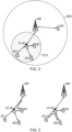
- Figure 2 schematically represents an example local cell arrangement.
- a base station eNB provides connectivity in a cell 203 (sometimes hereinafter referred to as a "base station cell” or simply “cell” if it is clear from the context that the cell is that provided by a base station).
- a UE "VC-UE” for Virtual Cell UE
- the VC-UE provides mobile connectivity to the three terminals UE1-UE3 while terminal UE4 is connected directly to the base station.
- only one virtual cell (“VC") is provided in the cell although in some examples more VC may be activated, or no VC may be activated.
- Figure 3 schematically represents examples communication paths in a local cell arrangement as illustrated in Figure 2 .
- the VC-UE provides UE3 with a wireless connectivity to the base station, for example to reach the core network or a remote destination outside of the mobile network (e.g. a public server available from the internet).
- UE3 is connected to the VC-UE and uses it as if it were a base station and the VC-UE sends the messages to the base station if need be (e.g. messages for a remote destination, the base station, the core network, etc.), thereby offering connectivity to the base station.
- a VC-UE can offer connectivity to other UEs in the local cell. For example, if UE1 and UE2 wish to communicate with each other, the VC-UE can identify that the destination for the messages is within its local cell and thus sends the messages directly to the destination. This feature is also expected to offload some of the traffic and traffic management load of the base station.
- the VC-UEs may communicate with the UEs in its local cell using a wireless interface provided on one or more unlicensed, shared licensed and/or licensed bands.
- VC-UEs can backhaul traffic to the network in any suitable way, although it is generally expected that it would be carried out using one or more licensed bands, for example to providing the backhauling over a wireless interface with a higher interference control.
- the VC-UE does not operate in the same manner as a terminal-to-base station relay node as currently discussed in the 3GPP consortium.
- a relay is for relaying messages the base station where the terminal is connected as an RRC layer with the base station, but not with the relay node.
- the terminal is connected to the relay which therefore operates more like an anchor than like a relay (in view of the present definition and use of 3GPP relays).
- the messages from UE1 to UE2 would go from UE1 to the relay, which would forward it to the base station and once it is returned by the base station for UE2, the relay node would forward it from the base station to UE2.
- a VC UE is expected not only to relay data but also to organize its local network/cell from a radio/connection control perspective. It is hope that by including such VC UEs in the network, certain aspects can be improved, e.g. by offloading some of the signalling overhead or of the resources allocation functions from the base station or by improving the efficiently of radio resource allocation, amongst other things.
- While the local cells are expected to assist the base station, they are also expected to be of a more transient nature than a base station, and even more so if they are provided by a terminal which may be mobile, run out of battery, etc. In other words, these local cells may assist the base station and network while they are in operation but they may also be activated and deactivated without notice which could leave the terminal out of a connection before a new connection is set up with the base station for the base station cell covering the local cell.
- a terminal and a base station can be either not connection, in a RRC_IDLE state or in a RRC_CONNECTED state.
- a terminal camping on a cell will be in RRC_IDLE and once it wants to send data to the base station, it will transition into the RRC_CONNECTED state.
- the base station will maintain RRC connection context information for all terminals in its cell that are communicating with/through it.
- the RRC_IDLE and RRC_CONNECTED states are defined as follows:
- Figure 4 schematically represents a possible control connection configuration in a local cell arrangement.
- the above problem can be addressed by having the terminal having a full RRC connection activated with the VC-UE (for using the local cell) and with the base station (in case the VC fails).
- the data would go through the VC-UE and, if it needs to be transmitted to the base station, then the VC-UE can forward it to the base station.
- the terminal and base station maintain an RRC connection ("RRC_CONNECTED" state) so that the UE can use the base station if the local cell fails and so that the base station can be aware of the presence of the terminal.
- RRC_CONNECTED RRC connection
- a terminal can have a full or high radio resource control connection with the mobile node providing a local cell and a limited or low radio resource control connection with the base station. Accordingly, some of the functionalities of the base station can be transposed to a mobile node providing a local cell while the terminal maintains only a limited connection with the base station, thereby minimising the overhead while facilitating a return to a base station's coverage if the local cell fails. In a 3GGP environment, this could be implemented by having different levels of RRC connectivity with the mobile node and with the base station.
- the mobile node can monitor the status (e.g. connected, idle) of UEs and manage the RRC connection between them, e.g.
- the present disclosure also aims at addressing the questions of how functions can be split between the base station and the mobile node; how the mobile node can manage the connection with its UEs (e.g. to set up/maintain/release the RRC or RRC-like connections in a 3GPP environment), what kinds of context information can be to transferred between UEs and the mobile nodes, etc.
- FIG. 5 schematically represents another possible control connection configuration in a local cell arrangement.
- UE1 can have a full RRC (or RRC-like) connection with the VC-UE, wherein the VC-UE can operate as an anchor for data transmission and can allocate resources within its VC, and a limited RRC (or RRC-like) connection with the base station.
- RRC RRC or RRC-like connections with the mobile nodes providing a VC
- RRC RRC or RRC-like connections with the base stations
- the UE1 can send data via the VC-UE and, at the same time, some connection -but a limited connection- remains with the base station.
- Figure 6 schematically represents example of transitions from different states relative to a base station cell and a local cell, wherein the terminal is originally only connected to the base station (full connection) and, at the end, is connected to both the VC-UE (full connection) and the base station (limited connection).
- the UE1 is only connected to the base station, in a conventional way, for transmitting messages to the base station.
- UE1 is in an RRC_CONNECTED state with the base station so that it can communicate with the base station over the radio interface.
- UE1 sets up a connection with a VC-UE so that the terminal can exchange data with the VC-UE over the wireless interface.
- the data can for example be transmitted, if appropriate, to the base station as illustrated in Figure 6 .
- the terminal can release the full RRC connection with the base station and transition to a partial or limited connection with the base station.
- the terminal transitions into a RRC_IDLE connection with the base station wherein the terminal remains connected to the base station but only with very limited functionalities available.
- the UE1 can then communicate using the local cell and VC-UE.
- UE1 can start exchanging messages with the local cell as soon as it has a full RRC connection with the mobile node (e.g. regardless of when the connection with the base station is downgraded or before it is downgraded), in other examples the terminal may first set up the connections with the VC-UE and base station and starts sending data only once the radio resource control connection with the base station has been transitioned from full to partial.
- Figure 7 schematically represents another example of transitions from different states relative to a base station cell and a local cell.
- the terminal is initially in a limited connection with the base station, for example in a RRC_IDLE state with the base station.
- the terminal may also be in a limited connection with the base station and thus have a limited radio resource control connection with both the mobile node for the local cell and the base station.
- UE1 transitioned to the full connected state with the mobile node (e.g. VC_RRC_CONNECTED state with the VC-UE) and keeps the limited RRC connection with the base station.
- UE1 Once UE1 is in a full connection mode with the VC-UE, it can then exchange messages with VC-UE over the wireless interface wherein at least of the messages and/or of their content may be transmitted by the VC-UE to the base station, if appropriate.
- Figure 8 schematically represents yet another example of transitions from different states relative to a base station cell and a local cell in which the terminal is initially in a dual-connected mode with a full connection with the VC-UE and a partial connection with the base station.
- the UE1 may be communicating via the local cell rather than the base station cell with a RRC connection set up as proposed herein.
- the terminal Once the terminal has completed its communications and wishes to return to an idle mode, it can transition from the VC_RRC_CONNECTED state to the VC_RRC_IDLE state and, at the same time, remain in the RRC_IDLE state with the base station. If UE1 later wishes to communicate, it can do so by transitioning back to the VC_RRC_CONNECTED state for using the local cell and to RRC_CONNECTED for using the base station cell.
- a radio resource control context may be maintained at the mobile node for the terminal and for the duration of the (full) connection with the terminal.
- context information may for example include one or more of: information regarding the configuration of data and/or signalling radio bearers; information regarding a radio link control configuration and/or state; security information (e.g. encryption related information); measurement configuration; information regarding the terminal's identity (e.g. C-RNTI).
- the base station does not generally maintain such a context for the terminal. For example, as the terminal's identifier is generally allocated to the terminal for communicating with it (e.g.
- the base station does not expect to maintain a context for the terminal with its identifier when the terminal is in an idle state.
- at least some of the radio resource control context at the mobile node and for the terminal is transmitted or notified to the base station. This can for example facilitates mobility from a VC to the cell or from a VC to another VC.
- the entire context information may be forwarded to the base station for the base station to maintain it for the terminal in RRC_IDLE, although it would generally be expected that the information that is mostly of use to the mobile node, and not to the base station, would not be transmitted to the base station.
- the base station is configured to maintain a limited context for a terminal which is in a RRC_IDLE state (or any other possible example of limited RRC state with the base station) and in a VC_RRC_CONNECTED state with a local cell.
- the limited context comprises an identifier for the terminal, the identifier being used by the mobile node to communicate with the terminal and/or being allocated to the terminal for the duration of the VC_RRC_CONNECTED state.
- radio resource control states may be defined for the terminal to have a full connection with the local cell and a limited connection with the base station.
- a "full" connection or a terminal being “fully” connected with one of a mobile node or a base station refers to a radio resource control (e.g. RRC in 3GPP) state in which the terminal can exchange user data and signalling with the mobile node or base station.
- a limited connection refers to a radio resource control state in which the terminal remains connected to the mobile node or base station but cannot exchange user data with the mobile node or base station.
- the terminal may be configured to do one or more of: monitoring and receiving paging information, carrying out measurements, handling mobility (e.g. to another VC or base station cell), etc.
- the functionalities available in the VC_RRC_IDLE and VC_RRC_CONNECTED states are defined as follows:
- the terminal can for example be expected to first enter the VC_RRC_IDLE state either when the UE has received a virtual cell notification message or when the UE receives a notification from the base station and then accesses the virtual cell.
- a notification can for example include the virtual cell ID for the local cell and, optionally, the type of communication (e.g. the communication accepted by the VC UE) and/or any other type of information that can be useful for the terminal to join the local cell (e.g. mobility of the VC-UE information).
- the base station may be made aware of it so that it can know how to reach the terminal. For example, the base station can then reach the terminal (e.g. for paging) via the VC or may be configured to determine whether to reach the terminal via the VC or via its own cell and proceed accordingly. For example, the mobile node may notify the base station of the terminal(s) that are in a VC_limited and/or VC_full state for its VC. Additionally or alternatively, the terminals themselves may be configured to notify the base station that it is connected to a VC.
- the terminal In cases where the terminal would have to transition to a connected state (with the base station or mobile node) to send such a notification, it may be preferable for the mobile node to notify the base station because the mobile node is more likely to already have a full connection with the base station. In other cases the terminal may be configured to re-use existing communication patterns to notify the base station, e.g. to send the notification alongside measurement reports it may already be configured to send to the base station.
- Examples of message exchanges for managing the VC_RRC states are further discuss below with reference to Figures 9-13 . While the examples have been provided in a 3GPP context and may thus have some similarities with existing RRC messages with a view to minimising the changes to existing techniques and mechanisms already in place (which can simplify the implementation of the techniques discussed herein), other messages may be used for setting a full or limited VC connection and thus for activating or transitioning into the corresponding full or limited radio connection states with the mobile node. In some cases, the message exchange may be different and/or the content of the messages may differ.
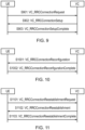
- Figure 9 represents an example call flow for setting up a control connection with a local cell.
- the call flow of Figure 9 starts with the UE being in a VC_RRC_IDLE (limited connection) state and transitioning into a VC_RRC_CONNECTED (full connection) state.
- Three messages are exchange in succession: first S901 for the terminal requesting a radio resource control connection with the mobile node (providing the VC), then at S902 a response from the mobile node that the request has been accepted and at S903, the terminal indicates that the connection setup has been completed.
- Example messages and content included in these messages are discussed below.
- the UE may be configured to use default configurations, e.g. regarding the physical channel configuration, MAC configuration, etc. to communicate with the mobile node when in VC_RRC_IDLE state. Then the VC-UE RRC connection establishment can be initiated with a VC_RRCConnectionRequest message from UE to the mobile node.
- This message can for example be carried on VC_SRB0, a VC Signalling Radio Bearer (SRB) which can be provided for use for RRC messages using a common control logical channel available for all the UEs in the virtual/local cell.
- SRB VC Signalling Radio Bearer
- a VC_SRB may be provided in a similar manner to the existing SRB provided by the base station in similar circumstances.
- the content of the message can for example include the following fields or information:
- a VC_RRCConnectionSetup message may then be sent from mobile node to the UE.
- this message can be carried out on a VC_SRB0.
- the message may in particular contain VC_SRB1 establishment information, where the VC_SRB1 is for the next RRC message (confirming the completion of the connection setup) using a dedicated control logical channel for the UE in the virtual cell.
- the content of the message can for example include the following fields or information:
- the terminal can transition into the VC_RRC_CONNECTED state (unless for example it decides not to go through with the connection of the mobile is expected to be too mobile for the terminal).
- the terminal can send a VC_RRCConnectionSetupComplete message to the mobile node to indicate that the RRC connection has been successfully established (in a full mode).
- This message may for example be carried on a radio bearer of VC_SRB1.
- the content of the message can for example include the following fields or information:
- the terminal may then fall back to attempting to establish a full radio connection with the base station cell so that it can communicate data with the base station directly rather than via a mobile node / local cell. It is noteworthy that this fall-back may be attempted regardless of the reason for the failure (e.g. whether the mobile node rejected the connection, the terminal rejected it for example due to the mobile node's mobility, etc.).
- the base station connection attempt may at least in part be based on the reason for the VC_RRC connection failure. For example, the terminal may report to the base station that it has previously attempted a VC connection -e.g. indicating the corresponding mobile node's ID- and the reason why this has not been successful.
- This information could be helpful for the network to assess how successful the VC_RRC connections are and/or to monitor the success rate and failure reasons for a specific mobile node. This information can assist in improving the network configuration.
- the procedure for setting up the RRC connection with the base station can remain the same whether the terminal is attempting a full RRC connection in a conventional manner or whether the terminal is attempting a full RRC connection as a fall-back following an unsuccessful full VC_RRC connection with the mobile node.
- Figure 10 represents an example call flow for reconfiguring a control connection with a local cell.
- This procedure may be used to modify an existing (full) VC_RRC connection. While the equivalent RRC procedure can be complex, this VC_RRC reconfiguration is expected to be less complex. In particular, it is expected that, in many cases, the VC may provide fewer functionalities than a conventional base station cell such that the VC radio control connection would then control fewer features and, as a result, the reconfiguration would be less complex.
- this procedure is expected to be used for one or more of establishing, modifying and/or releasing one or more radio bearers (e.g.
- VC_SRB1, VC_DRBs previously configured for the full radio connection between the UE and the mobile node; setting up, modifying and/or deleting measurement configurations; for performing a handover if necessary (e.g. to activate one of a fall-back to network or a handover to another virtual cell).
- This VC_RRCConnectionReconfiguration message is sent from the mobile node to the UE, e.g. on the radio bearer for VC_SRB1.
- the message may be used to convey some (re)configuration information e.g. DRB configuration, measurement configuration, radio resource configuration for modification, or certain NAS information if any.
- the content of the message can for example include the following fields or information:
- This message is for the terminal to confirm that the reconfiguration has been successful.
- the message can for example include a RRC transaction ID if provided and an indicator that the reconfiguration has been successful.
- the terminal can try a connection VC_RRC connection re-establishment procedure.
- This procedure may be used to re-establish the previously setup RRC connection, including for example the resumption of VC_SRB1 (if possible) and additional radio configuration of the local cell if necessary or appropriate.
- this occurs when the UE detects a UE-mobile node radio link failure, a handover failure (e.g. if the terminal attempted a handover to another local cell), a VC_RRC connection reconfiguration failure, etc. and the terminal can then initiate a VC-UE RRC connection re-establishment procedure.
- the entire RRC connection re-establishment may include two phases if necessary. First the UE can try to re-establish the VC_RRC connection with the mobile node and, if successful, the UE will remain in the VC_RRC_CONNECTED state. On the other hand, if the re-establishment fails, the UE can then try to re-establish or establish (e.g. if the UE was in a RRC_IDLE state with the base station) a full radio connection with the base station.
- the terminal while in most of the example when the terminal is in a partially / limited connected state with the base station, it can be in the RRC_IDLE state, in other examples the terminal may be in a different state, for example a newly defined RRC_PARTIAL state, with the base station, or in any other suitable limited radio connection state with the base station.
- whether the terminal will carry out a connection establishment or re-establishment procedure will depend on the terminology and conventions used for the state transitions and in particular used for a transition from a limited connection with the base station to a full connection to the base station. If this is successful, then the terminal will be in a full radio connection state with the base station (e.g.
- FIG. 11 represents an example call flow for re-establishing a control connection with a local cell.
- the terminal can send a VC_RRCConnectionReestablishment message to the mobile node, e.g. on the radio bearer VC_SRB0. It will include the contents as follows.
- the content of the message can for example include the following fields or information:
- This message can include a variety of information and, for example, the type and content of information that can be included can for example be derivable from the type/content of information present in the VC_RRC connection establishment request and/or from the corresponding RRC Connection re-establishment messages.
- this message is sent on the radio bearer VC_SRB0.
- the VC_SRB1 will be re-established with this message.
- the content of the message can for example include the following fields or information:
- the terminal can then confirm to the mobile node that the VC_RRC connection re-establishment procedure has been completed with a message like a VC_RRCConnectionReestablishmentComplete message.
- this message can include a variety of information and, for example, the type and content of information that can be included can for example be derivable from the type/content of information present in the VC_RRC connection establishment request and/or response, and/or from the corresponding RRC Connection re-establishment messages.
- Figure 12 represents an example call flow for re-establishing a control connection with a local cell with a fall-back on a base station call.
- This message is similar to that sent at S1101 such that its discussion will not be repeated again.
- the mobile node rejects the VC_RRC connection re-establishment in response to the connection re-establishment request.
- This message can for example include information identifying that it is for the terminal and/or in response to the message received at S1201, and may also include information identifying a rejection (connection re-establishment failure) cause if appropriate.
- the terminal determines that the connection re-establishment with the mobile node has failed and it can attempt to fall-back to the base station cell with messages S1203 (and S1203' discussed bellow).
- the conventional RRC connection re-establishment procedure can be followed, or any other equivalent radio control connection re-establishment procedure can be implemented.
- the terminal may for example indicate that it is attempting to re-connect to the base station following a failure of a local cell radio control connection.
- the base station may also maintain some context information for the VC_RRC connections of the terminals in its cell such that the base station may be able to identify which VC radio full connection is being re-established and the mobile node that was previously connected in full mode with the terminal.
- This message may include a variety of information, in addition to the convention information that can be included in these message and the terminal may for example include an identifier for the VC_RRC full connection that has failed, an identifier for the mobile, a cause for the connection failure, etc. if appropriate.
- connection with the base station is successful and the base station responds with a positive answer to the connection request.
- This can for example be similar and/or adapted from the existing radio control (e.g. RRC) messages exchanged with the base station in a conventional arrangement.
- RRC radio control
- the RRC connection re-establishment procedure for a fall-back to the base station cell can involve a three message exchange as well with a connection re-establishment.
- the exchange may terminate upon the transmission of a confirmation of the completion of the connection re-establishment completion from the terminal.
- the terminal once the terminal has received the confirmation from the base station that the connection is being re-established, it can change to the RRC_CONNECTED state and send the completion confirmation to the base station.
- S1203 is for the terminal to attempt to fall-back to the base station and the same teachings as discussed in respect of S1203 can be applied to this message.
- the base station rejects the connection re-establishment request receives from the terminal.
- the base station can for example include a cause for refusing to allow to connection in its rejection message and/or provide the terminal with any suitable information.
- the terminal is generally expected to remain in the RRC_IDLE state
- the terminal may for example not attempt a fall-back procedure with the base station cell if the connection with the local cell fails, as the terminal is already connected with the base station.
- the terminal and/or the mobile node may in some examples (e.g. when the base maintains a record and/or context of the current VC connection -or at least of the VC full connection) notify the base station that the connection previously established has now failed.
- connection re-establishment request from the terminal with the base station mentions a connection re-establishment request from the terminal with the base station
- the procedure can be viewed as a connection establishment procedure with the base station in cases where the terminal was in a limited connection with the mobile node.
- the main elements to be considered in this fall-back case is that the terminal can try to ensure that it has at least a full radio resources control connection with the base station and, if the system operates in a mode where the base station maintains or is notified of information regarding the local cell connection information for the terminal, the base station may be notified one way or another that the terminal is no longer connected to the mobile node and may be trying to send its user data to the base station as a result.
- Figure 13 represents an example call flow for releasing a control connection with a local cell.
- This procedure can be used for the mobile node to release the radio control connection between the terminal and the mobile node. It can for example involve the release of the previously established radio bearers (e.g. VC_SRB1 and VC_DRBs) and/or the radio resources in accordance with the radio resource control procedures and techniques in use.
- the UE can transition into the VC limited radio control connection (e.g. VC_RRC_IDLE) state.
- the mobile node can send a VC_RRCConnectionRelease message to the terminal, e.g. on the radio bearer VC_SRB1 previously established for the VC_RRC connection.
- the terminal may reply to the message sent at S1301, e.g. to confirm receipt, while in other examples the procedure may terminate at this message and the terminal may not be expected to respond.
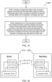
- FIG 14 illustrates an example method for use in a mobile telecommunications network or system.
- the mobile telecommunications network or system comprises a base station providing wireless connectivity within a base station cell, a mobile node providing wireless connectivity within a local cell and configured to communicate with the base station as well as a terminal configured to communicate wirelessly with either or both the base station the mobile node.
- the method starts and at S1401 a limited base station radio connection between the terminal and the base station is activated.
- this limited base station radio connection is activated, the terminal and base station are not operable to exchange user data such that, while they are connected to each other, they are limited to some signalling or control communications and are not configured to communicate user data such as application data.
- the method also comprises step S1402 wherein one of a full local radio connection and a limited local radio connection between the terminal and the mobile node is activated.
- the terminal and base station can exchange user data and when the limited local radio connection is activated, the terminal and base station cannot exchange user data with the mobile node.
- a terminal can be in a limited connection with the base station while it can be in a limited or full connection with a mobile node.
- the terminal can be primarily served by the local cell while a fall-back to the base station cell, if appropriate, can be efficiently carried out.
- the signalling overhead and load on the base station can be reduced compared to a case where the terminal is in a full connection with the base station. It is noteworthy that the terminal is also not in a full connection with the base station while it is effectively still being served by the base station -via the mobile node- when it is exchanging user or application data.
- the limited connected mode or state that is activated with the base station while the terminal is connected (in full or limited mode) with a VC-UE can be based on the RRC_IDLE or RRC_CONNECTED mode where some functionalities have been de-activated.
- the terminal may be configure to carry out: paging, system information acquisition and UE controlled mobility but not the following RRC functionalities:
- a UE specific DRX may be configured by upper layers, The UE performs neighbouring cell measurements and cell (re-)selection based on configuration information from the base station (for example the UE may not receive measurement configuration from the base station in cases where the UE already receives measurement configuration from the local/virtual cell); and the UE performs logging of available measurements together with location and time for logged measurement configured UEs.
- the terminal is not able to communicate data with the base station and this remains the case in the limited state derived from the RRC_IDLE state.
- C-RNTI will be recorded;
- Radio bearer between UE and eNB is remained;
- Network controlled mobility if based on the RRC_CONNECTED state, the following functionalities may be maintained: (i) C-RNTI will be recorded; (ii) Radio bearer between UE and eNB is remained; (iii) Network controlled mobility and (iv) Acquire system information.
- the following functionalities may not be maintained: (i) Transfer of unicast data to/from UE; (ii) At lower layers, the UE may be configured with a UE specific DRX; (iii) The UE: monitors control channels associated with the shared data channel to determine if data is scheduled for it; provides channel quality and feedback information; and performs neighbouring cell measurements and measurement reporting based on configuration information from the base station (likewise, if this type of functionality is already configured by the VC, the UE may not have to have it configured by the base station as well).
- Figure 15 illustrates an example terminal (1510) and an example base station (1520) configured to communicate with each other and which may implement one or more techniques as discussed herein.
- the terminal 1510 comprises a receiver 1511 and a transmitter 1512 connected to an antenna for communicating via a wireless interface.
- the terminal also comprises a controller 1513 for controlling at least the receiver and transmitter of the terminal 1510.
- the terminal may be configured such that the controller, receiver and transmitter may be configured to operate together to operate as a mobile node to provide a local cell to neighbouring terminals.
- the base station 1520 comprises a receiver 1521 and a transmitter 1522 connected to an antenna for communicating via a wireless interface.
- the base station 1520 also comprises a controller 1523 for controlling at least the receiver and transmitter of the base station 1520.
- the base station and terminal can communicate over the air, via the wireless interface by transmitting uplink signals from the terminal to the base station and downlink signals from the base station to the terminal.
- a mobile node in accordance with the present disclosure may also have the same structure as the terminal and/or base station. Although it is generally expected that terminals will be providing local cell functionality, any other suitable node may be providing this functionality.
- each terminal includes a transmitter, receiver and controller and each base station includes a transmitter, receiver and controller so as to allow communication between the terminals and/or base stations
- the terminal and base station may be implemented using any appropriate technique.
- the controller may comprise one or more processor units which are suitably configured / programmed to provide the desired functionality described herein using conventional programming / configuration techniques for equipment in wireless telecommunications systems.
- the transmitter, receiver and controller are schematically shown in Figure 15 as separate elements for ease of representation.
- each terminal the functionality of these units can be provided in various different ways, for example using a single suitably programmed general purpose computer, or suitably configured application-specific integrated circuit(s) / circuitry, or using a plurality of discrete circuitry / processing elements for providing different elements of the desired functionality.
- the terminals will in general comprise various other elements associated with their operating functionality in accordance with established wireless telecommunications techniques (e.g. a power source, possibly a user interface, and so forth).
- the prefix RRC has been used for states and connections with the base station and the prefix VC_RRC for states and connections with the mobile node for the local cell. It is noteworthy that these have been used in the interest of conciseness and that, unless they are being used specifically in the context RRC only, they are not limited to connections or states of the 3GPP (or equivalent) RRC protocol and are also intended to refer to any other radio resources control protocol.
- radio resources control protocol procedure, states or connections
- radio resources control protocol procedure, states or connections
- radio control or radio resources protocol procedure, states or connections
- the term mobile node is used to refer to the node providing the local/virtual cell and the mobile node functionality may be provided by a terminal, a relay node, a base station, a dedicated node, or any other suitable node.
- steps discussed herein may be carried out in any suitable order.
- steps may be carried out in an order which differs from an order used in the examples discussed above or from an indicative order used anywhere else for listing steps (e.g. in the claims), whenever possible or appropriate.
- some steps may be carried out in a different order, or simultaneously or in the same order.
- S1501 and S1502 may be carried out in any suitable order, such as one after the other or at least partially in parallel. So long as an order for carrying any of the steps of any method discussed herein is technically feasible, it is explicitly encompassed within the present disclosure.
- transmitting information or a message to an element may involve sending one or more messages to the element and may involve sending part of the information separately from the rest of the information.
- the number of "messages" involved may also vary depending on the layer or granularity considered. For example transmitting a message may involve using several resource elements in an LTE environment such that several signals at a lower layer correspond to a single message at a higher layer.
- transmissions from one terminal to another may relate to the transmission of any one or more of user data, discovery information, control signalling and any other type of information to be transmitted.
- any suitable element or elements that can carry out the function can be configured to carry out this function or step.
- any one or more of a terminal, a mobile node, a base station or any other mobile node may be configured accordingly if appropriate, so long as it is technically feasible and not explicitly excluded.
Landscapes
- Engineering & Computer Science (AREA)
- Computer Networks & Wireless Communication (AREA)
- Signal Processing (AREA)
- Mobile Radio Communication Systems (AREA)
Claims (12)
- Verfahren zur Verwendung in einem Mobiltelekommunikationsnetzwerk, wobei das Mobiltelekommunikationsnetzwerk eine Basisstation (1520), die drahtlose Konnektivität innerhalb einer Basisstationszelle (203) bereitstellt, einen Mobilknoten, der drahtlose Konnektivität innerhalb einer lokalen Zelle (213) bereitstellt und für die Kommunikation mit der Basisstation konfiguriert ist, und ein Endgerät (1510), das für die drahtlose Kommunikation mit der Basisstation konfiguriert ist und für die drahtlose Kommunikation mit dem Mobilknoten konfiguriert ist, umfasst, wobei der Mobilknoten eine direkte Kommunikation von Signalen zwischen dem Endgerät und einem zweiten Endgerät über den Mobilknoten ohne Übertragung der Signale an die Basisstation ermöglicht und der Mobilknoten Funkverbindungen zwischen dem Endgerät und dem Mobilknoten steuert; das Verfahren umfassend:bei Aktivierung einer vollständigen Basisstations-Funkverbindung zwischen dem Endgerät und der Basisstation, Zuweisen einer Funkkennung an das Endgerät, wobei das Endgerät in der vollständigen Basisstations-Funkverbindung in einem RRC_CONNECTED-Zustand mit der Basisstation arbeitet;Aktivieren (S1401) einer eingeschränkten Basisstations-Funkverbindung zwischen dem Endgerät und der Basisstation, in der das Endgerät in einem RRC_IDLE-Zustand mit der Basisstation arbeitet; undAktivieren (S1402) einer von einer vollständigen lokalen Funkverbindung zwischen dem Endgerät und dem Mobilknoten, in der das Endgerät in einem RRC_CONNECTED-Zustand mit dem Mobilknoten arbeitet, und einer eingeschränkten lokalen Funkverbindung zwischen dem Endgerät und dem Mobilknoten, in der das Endgerät in einem anderen RRC-Zustand als dem RRC_CONNECTED-Zustand oder dem RRC_IDLE-Zustand mit dem Mobilknoten arbeitet,die Funkkennung wird dem Endgerät bei Aktivierung der vollständigen Basisstations-Funkverbindung zwischen dem Endgerät und der Basisstation zugewiesen, unddas Aktivieren einer von der vollständigen lokalen Funkverbindung und der eingeschränkten lokalen Funkverbindung zwischen dem Endgerät und dem Mobilknoten umfasst, dass das Endgerät dem Mobilknoten die Funkkennung mitteilt, die bei der Aktivierung der vollständigen Basisstations-Funkverbindung zwischen dem Endgerät und der Basisstation zugewiesen wurde.
- Verfahren nach Anspruch 1, wobeiwenn die eingeschränkte Basisstations-Funkverbindung aktiviert ist, das Endgerät und die Basisstation nicht betreibbar sind, um Benutzerdaten auszutauschen; und/oderwenn die vollständige lokale Funkverbindung aktiviert ist, das Endgerät und der Mobilknoten betreibbar sind, um Benutzerdaten auszutauschen; und/oderwenn die eingeschränkte lokale Funkverbindung aktiviert ist, das Endgerät und der Mobilknoten nicht betreibbar sind, um Benutzerdaten auszutauschen.
- Verfahren nach Anspruch 1, ferner umfassend das Aktivieren der vollständigen lokalen Funkverbindung und das Aktivieren einer vollständigen Mobilknoten-Funkverbindung zwischen dem Mobilknoten und der Basisstation.
- Verfahren nach Anspruch 1, ferner umfassend:Aktivieren der vollständigen lokalen Funkverbindung, unddas Endgerät tauscht Benutzerdaten mit dem Mobilknoten aus, während die eingeschränkte Basisstations-Funkverbindung aktiviert ist und während die vollständige lokale Funkverbindung aktiviert ist.
- Verfahren nach Anspruch 1, wobei der Mobilknoten eines von einem Endgerät, einem Relaisknoten, einem Gerät-zu-Gerät-Relaisknoten, ein dedizierter lokaler Zellen-Mobilknoten ist.
- Mobiltelekommunikationsnetzwerk, wobei das Mobiltelekommunikationsnetzwerk eine Basisstation (1520), die drahtlose Konnektivität innerhalb einer Basisstationszelle (203) bereitstellt, einen Mobilknoten, der drahtlose Konnektivität innerhalb einer lokalen Zelle (213) bereitstellt und für die Kommunikation mit der Basisstation konfiguriert ist, und ein Endgerät (1510), das für die drahtlose Kommunikation mit der Basisstation konfiguriert ist und für die drahtlose Kommunikation mit dem Mobilknoten konfiguriert ist, umfasst, wobei der Mobilknoten eine direkte Kommunikation von Signalen zwischen dem Endgerät und einem zweiten Endgerät über den Mobilknoten ohne Übertragung der Signale an die Basisstation ermöglicht und der Mobilknoten Funkverbindungen zwischen dem Endgerät und dem Mobilknoten steuert; wobei das Mobiltelekommunikationsnetzwerk konfiguriert ist zum:Zuweisen, bei Aktivierung einer vollständigen Basisstations-Funkverbindung zwischen dem Endgerät und der Basisstation, einer Funkkennung an das Endgerät, wobei das Endgerät in der vollständigen Basisstations-Funkverbindung in einem RRC_CONNECTED-Zustand mit der Basisstation arbeitet;Aktivieren einer eingeschränkten Basisstations-Funkverbindung zwischen dem Endgerät und der Basisstation, in der das Endgerät in einem RRC_IDLE-Zustand mit der Basisstation arbeitet; undAktivieren einer vollständigen lokalen Funkverbindung zwischen dem Endgerät und dem Mobilknoten, in der das Endgerät in einem RRC_CONNECTED-Zustand mit dem Mobilknoten arbeitet, oder einer eingeschränkten lokalen Funkverbindung zwischen dem Endgerät und dem Mobilknoten, in der das Endgerät in einem anderen RRC-Zustand als dem RRC_CONNECTED-Zustand oder dem RRC_IDLE-Zustand mit dem Mobilknoten arbeitet,die Funkkennung wird dem Endgerät bei Aktivierung der vollständigen Basisstations-Funkverbindung zwischen dem Endgerät und der Basisstation zugewiesen, unddas Konfigurieren des Netzwerks so, dass es die vollständige lokale Funkverbindung oder die eingeschränkte lokale Funkverbindung zwischen dem Endgerät und dem Mobilknoten aktiviert, umfasst, dass das Endgerät so konfiguriert ist, dass es dem Mobilknoten die Funkkennung mitteilt, die bei Aktivierung der vollständigen Basisstations-Funkverbindung zwischen dem Endgerät und der Basisstation zugewiesen wurde.
- Verfahren zum Betreiben eines Endgeräts (1510) zur Verwendung in einem Mobiltelekommunikationsnetzwerk, wobei das Mobiltelekommunikationsnetzwerk eine Basisstation (1520), die eine drahtlose Konnektivität innerhalb einer Basisstationszelle (203) bereitstellt, einen Mobilknoten, der eine drahtlose Konnektivität innerhalb einer lokalen Zelle (213) bereitstellt und für die Kommunikation mit der Basisstation konfiguriert ist, umfasst; wobei das Endgerät einen Sender (1512), einen Empfänger (1511) und eine Steuerung (1513) umfasst und zur drahtlosen Kommunikation mit der Basisstation konfiguriert ist und zur drahtlosen Kommunikation mit dem Mobilknoten konfiguriert ist, wobei der Mobilknoten eine direkte Kommunikation von Signalen zwischen dem Endgerät und einem zweiten Endgerät über den Mobilknoten ohne Übertragung der Signale an die Basisstation ermöglicht und der Mobilknoten Funkverbindungen zwischen dem Endgerät und dem Mobilknoten steuert; das Verfahren umfassend:bei Aktivierung einer vollständigen Basisstations-Funkverbindung zwischen dem Endgerät und der Basisstation, Identifizieren einer zugewiesenen Funkkennung für das Endgerät durch das Endgerät, wobei das Endgerät in der vollständigen Basisstations-Funkverbindung in einem RRC_CONNECTED-Zustand mit der Basisstation arbeitet;Aktivieren (S1401), durch das Endgerät, einer eingeschränkten Basisstations-Funkverbindung zwischen dem Endgerät und der Basisstation, wobei das Endgerät in einem RRC_IDLE-Zustand mit der Basisstation arbeitet; undAktivieren (S1402), durch das Endgerät, einer vollständigen lokalen Funkverbindung zwischen dem Endgerät und dem Mobilknoten, in der das Endgerät in einem RRC_CONNECTED-Zustand mit dem Mobilknoten arbeitet, oder einer eingeschränkten lokalen Funkverbindung zwischen dem Endgerät und dem Mobilknoten, in der das Endgerät in einem anderen RRC-Zustand als dem RRC_CONNECTED-Zustand oder dem RRC_IDLE-Zustand mit dem Mobilknoten arbeitet,das Endgerät identifiziert die Funkkennung für das Endgerät bei Aktivierung der vollständigen Basisstations-Funkverbindung zwischen dem Endgerät und der Basisstation, unddas Aktivieren, durch das Endgerät, der vollständigen lokalen Funkverbindung oder der eingeschränkten lokalen Funkverbindung zwischen dem Endgerät und dem Mobilknoten umfasst, dass das Endgerät dem Mobilknoten die Funkkennung mitteilt, die bei Aktivierung der vollständigen Basisstations-Funkverbindung zwischen dem Endgerät und der Basisstation zugewiesen wurde.
- Endgerät (1510) zur Verwendung in einem Mobiltelekommunikationsnetzwerk, wobei das Mobiltelekommunikationsnetzwerk eine Basisstation (1520), die eine drahtlose Konnektivität innerhalb einer Basisstationszelle (203) bereitstellt, einen Mobilknoten, der eine drahtlose Konnektivität innerhalb einer lokalen Zelle (213) bereitstellt und für die Kommunikation mit der Basisstation konfiguriert ist, umfasst; wobei das Endgerät einen Sender (1512), einen Empfänger (1511) und eine Steuerung (1513) umfasst und zur drahtlosen Kommunikation mit der Basisstation konfiguriert ist und zur drahtlosen Kommunikation mit dem Mobilknoten konfiguriert ist, wobei der Mobilknoten eine direkte Kommunikation von Signalen zwischen dem Endgerät und einem zweiten Endgerät über den Mobilknoten ohne Übertragung der Signale an die Basisstation ermöglicht und der Mobilknoten Funkverbindungen zwischen dem Endgerät und dem Mobilknoten steuert, wobei das Endgerät ferner konfiguriert ist zum:Identifizieren, bei Aktivierung einer vollständigen Basisstations-Funkverbindung zwischen dem Endgerät und der Basisstation, einer zugewiesenen Funckennung für das Endgerät, wobei das Endgerät in der vollständigen Basisstations-Funkverbindung in einem RRC_CONNECTED-Zustand mit der Basisstation arbeitet;Aktivieren einer eingeschränkten Basisstations-Funkverbindung zwischen dem Endgerät und der Basisstation, in der das Endgerät in einem RRC_IDLE-Zustand mit der Basisstation arbeitet; undAktivieren einer vollständigen lokalen Funkverbindung zwischen dem Endgerät und dem Mobilknoten, in der das Endgerät in einem RRC_CONNECTED-Zustand mit dem Mobilknoten arbeitet, oder einer eingeschränkten lokalen Funkverbindung zwischen dem Endgerät und dem Mobilknoten, in der das Endgerät in einem anderen RRC-Zustand als dem RRC_CONNECTED-Zustand oder dem RRC_IDLE-Zustand mit dem Mobilknoten arbeitet,das Endgerät identifiziert die Funkkennung für das Endgerät bei Aktivierung der vollständigen Basisstations-Funkverbindung zwischen dem Endgerät und der Basisstation, unddas Konfigurieren des Endgeräts so, dass es die vollständige lokale Funkverbindung oder die eingeschränkte lokale Funkverbindung zwischen dem Endgerät und dem Mobilknoten aktiviert, umfasst, dass das Endgerät so konfiguriert ist, dass es dem Mobilknoten die Funkkennung mitteilt, die bei Aktivierung der vollständigen Basisstations-Funkverbindung zwischen dem Endgerät und der Basisstation zugewiesen wurde.
- Verfahren zum Betreiben eines Mobilknotens in einem Mobiltelekommunikationsnetzwerk, wobei das Mobiltelekommunikationsnetzwerk eine Basisstation (1520) umfasst, die drahtlose Konnektivität innerhalb einer Basisstationszelle (203) bereitstellt, wobei der Mobilknoten dazu konfiguriert ist, drahtlose Konnektivität innerhalb einer lokalen Zelle (213) bereitzustellen und dazu konfiguriert ist, mit der Basisstation zu kommunizieren; und ein Endgerät (1510), das zur drahtlosen Kommunikation mit der Basisstation konfiguriert ist und zur drahtlosen Kommunikation mit dem Mobilknoten konfiguriert ist, wobei der Mobilknoten eine direkte Kommunikation von Signalen zwischen dem Endgerät und einem zweiten Endgerät über den Mobilknoten ohne Übertragung der Signale an die Basisstation ermöglicht und der Mobilknoten Funkverbindungen zwischen dem Endgerät und dem Mobilknoten steuert, wobei das Verfahren umfasst, dass der Mobilknoten Folgendes durchführt:Aktivieren (S1402) einer vollständigen lokalen Funkverbindung mit dem Endgerät, in der das Endgerät in einem RRC_CONNECTED-Zustand mit dem Mobilknoten arbeitet, oder einer eingeschränkten lokalen Funkverbindung mit dem Endgerät, in der das Endgerät in einem anderen RRC-Zustand als dem RRC_CONNECTED-Zustand oder dem RRC_IDLE-Zustand mit dem Mobilknoten arbeitet, während eine eingeschränkte Basisstations-Funkverbindung zwischen dem Endgerät und der Basisstation aktiviert ist, in der das Endgerät in dem RRC_IDLE-Zustand mit der Basisstation arbeitet,das Aktivieren der vollständigen lokalen Funkverbindung oder der eingeschränkten lokalen Funkverbindung zwischen dem Endgerät und dem Mobilknoten umfasst das Empfangen, von dem Endgerät, einer Benachrichtigung über eine Funkkennung für das Endgerät,wobei die Funkkennung dem Endgerät bei Aktivierung einer vollständigen Basisstations-Funkverbindung zwischen dem Endgerät und der Basisstation zugewiesen wird, wobei das Endgerät in der vollständigen Basisstations-Funkverbindung im RRC_CONNECTED-Zustand mit der Basisstation arbeitet.
- Mobilknoten zur Verwendung in einem Mobiltelekommunikationsnetzwerk, wobei das Mobiltelekommunikationsnetzwerk eine Basisstation (1520) umfasst, die drahtlose Konnektivität innerhalb einer Basisstationszelle (203) bereitstellt, wobei der Mobilknoten dazu konfiguriert ist, drahtlose Konnektivität innerhalb einer lokalen Zelle (213) bereitzustellen und dazu konfiguriert ist, mit der Basisstation zu kommunizieren; und ein Endgerät (1510), das zur drahtlosen Kommunikation mit der Basisstation konfiguriert ist und zur drahtlosen Kommunikation mit dem Mobilknoten konfiguriert ist, wobei der Mobilknoten eine direkte Kommunikation von Signalen zwischen dem Endgerät und einem zweiten Endgerät über den Mobilknoten ohne Übertragung der Signale an die Basisstation ermöglicht und der Mobilknoten Funkverbindungen zwischen dem Endgerät und dem Mobilknoten steuert, wobei der Mobilknoten einen Sender, einen Empfänger und eine Steuerung umfasst und konfiguriert ist zum:Aktivieren einer vollständigen lokalen Funkverbindung mit dem Endgerät, in der das Endgerät in einem RRC_CONNECTED-Zustand mit dem Mobilknoten arbeitet, oder einer eingeschränkten lokalen Funkverbindung mit dem Endgerät, in der das Endgerät in einem anderen RRC-Zustand als dem RRC_CONNECTED-Zustand oder dem RRC_IDLE-Zustand mit dem Mobilknoten arbeitet, während eine eingeschränkte Basisstations-Funkverbindung zwischen dem Endgerät und der Basisstation aktiviert ist, in der das Endgerät in dem RRC_IDLE-Zustand mit der Basisstation arbeitet,das Konfigurieren des Mobilknotens so, dass er die vollständige lokale Funkverbindung oder die eingeschränkte lokale Funkverbindung zwischen dem Endgerät und dem Mobilknoten aktiviert, umfasst, dass der Mobilknoten so konfiguriert ist, dass er von dem Endgerät eine Benachrichtigung über eine Funckennung für das Endgerät empfängt,wobei die Funkkennung dem Endgerät bei Aktivierung einer vollständigen Basisstations-Funkverbindung zwischen dem Endgerät und der Basisstation zugewiesen wird, wobei das Endgerät in der vollständigen Basisstations-Funkverbindung im RRC_CONNECTED-Zustand mit der Basisstation arbeitet.
- Computersoftware, die, wenn sie durch einen Computer ausgeführt wird, den Computer veranlasst, das Verfahren nach einem der Ansprüche 1, 7 und 9 durchzuführen.
- Speichermedium, das Computersoftware nach Anspruch 11 speichert.
Applications Claiming Priority (2)
| Application Number | Priority Date | Filing Date | Title |
|---|---|---|---|
| EP15193709 | 2015-11-09 | ||
| PCT/EP2016/072436 WO2017080704A1 (en) | 2015-11-09 | 2016-09-21 | Telecommunications apparatuses and methods |
Publications (2)
| Publication Number | Publication Date |
|---|---|
| EP3375244A1 EP3375244A1 (de) | 2018-09-19 |
| EP3375244B1 true EP3375244B1 (de) | 2024-10-30 |
Family
ID=54548030
Family Applications (1)
| Application Number | Title | Priority Date | Filing Date |
|---|---|---|---|
| EP16775545.3A Active EP3375244B1 (de) | 2015-11-09 | 2016-09-21 | Telekommunikationsvorrichtungen und -verfahren |
Country Status (3)
| Country | Link |
|---|---|
| US (2) | US11064558B2 (de) |
| EP (1) | EP3375244B1 (de) |
| WO (1) | WO2017080704A1 (de) |
Families Citing this family (8)
| Publication number | Priority date | Publication date | Assignee | Title |
|---|---|---|---|---|
| US10404866B2 (en) | 2010-03-31 | 2019-09-03 | Incnetworks, Inc. | System, network, device and stacked spectrum method for implementing spectrum sharing of multiple contiguous and non-contiguous spectrum bands utilizing universal wireless access gateways to enable dynamic security and bandwidth policy management |
| WO2017108487A1 (en) | 2015-12-21 | 2017-06-29 | Sony Corporation | Telecommunications apparatus and methods |
| CN116669112A (zh) * | 2017-01-26 | 2023-08-29 | 中兴通讯股份有限公司 | 通信方法、网络设备、计算机存储介质 |
| EP3603250B1 (de) | 2017-03-24 | 2020-05-27 | Telefonaktiebolaget LM Ericsson (publ) | Steuerung von uplink-funkübertragungen auf semipermanent zugewiesenen ressourcen |
| WO2019096912A1 (en) * | 2017-11-15 | 2019-05-23 | Sony Corporation | To reduce power consumption for all types of terminal device |
| US11509775B2 (en) * | 2017-12-18 | 2022-11-22 | Incnetworks, Inc. | System, network, device and stacked spectrum method for implementing spectrum sharing of multiple contiguous and non-contiguous spectrum bands utilizing universal wireless access gateways to enable dynamic security and bandwidth policy management |
| WO2022193115A1 (en) * | 2021-03-16 | 2022-09-22 | Qualcomm Incorporated | Puncturing of inter-frequency measurements during evolved packet system fallback call procedure |
| US12245234B2 (en) * | 2021-08-02 | 2025-03-04 | Qualcomm Incorporated | On demand assistance for sidelink mode 1 communication |
Family Cites Families (16)
| Publication number | Priority date | Publication date | Assignee | Title |
|---|---|---|---|---|
| JP5078807B2 (ja) * | 2008-08-28 | 2012-11-21 | 京セラ株式会社 | 無線通信システム、無線基地局、無線中継局および無線通信方法 |
| WO2010034349A1 (en) * | 2008-09-26 | 2010-04-01 | Nokia Siemens Networks Oy | Control signaling in system supporting relayed connections |
| US8532056B2 (en) * | 2009-04-13 | 2013-09-10 | Qualcomm Incorporated | Device mobility for split-cell relay networks |
| WO2013086316A1 (en) * | 2011-12-08 | 2013-06-13 | Interdigital Patent Holdings, Inc. | Method and apparatus for cross link establishment |
| EP3211960A1 (de) * | 2011-12-08 | 2017-08-30 | Interdigital Patent Holdings, Inc. | Basisstation zum auswählen einer hilfseinheit mit drahtlosübertragung und -empfang |
| GB2500720A (en) * | 2012-03-30 | 2013-10-02 | Nec Corp | Providing security information to establish secure communications over a device-to-device (D2D) communication link |
| WO2014003500A1 (ko) * | 2012-06-29 | 2014-01-03 | 엘지전자 주식회사 | 무선 통신 시스템에서 핸드오버 제어 방법 및 이를 위한 장치 |
| EP3070976B1 (de) * | 2012-09-10 | 2017-05-17 | Fujitsu Limited | Verbrauchergerät, basisstation und entsprechendes handoververfahren |
| KR102039908B1 (ko) * | 2013-04-01 | 2019-11-04 | 삼성전자주식회사 | 단말간 통신을 위한 상태 천이 방법 및 장치 |
| US20140321367A1 (en) * | 2013-04-26 | 2014-10-30 | Sprint Communications Company L.P. | Wireless communication system with multiple device-to-device (d2d) communication configurations |
| US20160219636A1 (en) * | 2013-08-28 | 2016-07-28 | Kyocera Corporation | User terminal and mobile communication system |
| WO2015054256A1 (en) * | 2013-10-08 | 2015-04-16 | Futurewei Technologies, Inc. | Operating states for d2d discovery |
| US9451501B2 (en) * | 2013-10-24 | 2016-09-20 | Sprint Communications Company L.P. | Wireless access node and method for signaling aggregation of a plurality of UE devices through a hub UE device |
| WO2015162640A1 (ja) * | 2014-04-22 | 2015-10-29 | 富士通株式会社 | 無線端末、無線局、無線通信システム、および無線通信方法 |
| US10356656B2 (en) * | 2015-04-07 | 2019-07-16 | Lg Electronics Inc. | Method and apparatus for performing buffer status reporting procedure for relaying in wireless communication system |
| US10542414B2 (en) * | 2015-09-25 | 2020-01-21 | Lg Electronics Inc. | Method for performing device-to-device direct communication in wireless communication system and device therefor |
-
2016
- 2016-09-21 EP EP16775545.3A patent/EP3375244B1/de active Active
- 2016-09-21 US US15/772,409 patent/US11064558B2/en active Active
- 2016-09-21 WO PCT/EP2016/072436 patent/WO2017080704A1/en not_active Ceased
-
2021
- 2021-06-21 US US17/352,360 patent/US20210315048A1/en not_active Abandoned
Also Published As
| Publication number | Publication date |
|---|---|
| US20210315048A1 (en) | 2021-10-07 |
| US20180324891A1 (en) | 2018-11-08 |
| WO2017080704A1 (en) | 2017-05-18 |
| US11064558B2 (en) | 2021-07-13 |
| EP3375244A1 (de) | 2018-09-19 |
Similar Documents
| Publication | Publication Date | Title |
|---|---|---|
| EP3375244B1 (de) | Telekommunikationsvorrichtungen und -verfahren | |
| US12075511B2 (en) | Method and device for indicating type of bearer used for next message in wireless communication system | |
| US12133195B2 (en) | Wireless telecommunications apparatuses and methods | |
| US12069772B2 (en) | Telecommunications apparatuses and methods | |
| CN112042259B (zh) | 用于在无线通信系统中执行通信的方法和装置 | |
| US10548174B2 (en) | Telecommunications apparatuses and methods | |
| EP3016469B1 (de) | Verfahren und vorrichtung zur modusumschaltung | |
| CN108617020B (zh) | 一种用于建立控制面连接的方法和系统 | |
| US11653410B2 (en) | Telecommunications apparatus and methods | |
| EP3751953B1 (de) | Rrc-zustandsübergangsverfahren, cu und du | |
| US20220287126A1 (en) | Sidelink transmission continuity | |
| US11564208B1 (en) | Method and apparatus for radio resource allocation to support UE-to-network relaying in a wireless communication system |
Legal Events
| Date | Code | Title | Description |
|---|---|---|---|
| STAA | Information on the status of an ep patent application or granted ep patent |
Free format text: STATUS: THE INTERNATIONAL PUBLICATION HAS BEEN MADE |
|
| PUAI | Public reference made under article 153(3) epc to a published international application that has entered the european phase |
Free format text: ORIGINAL CODE: 0009012 |
|
| STAA | Information on the status of an ep patent application or granted ep patent |
Free format text: STATUS: REQUEST FOR EXAMINATION WAS MADE |
|
| 17P | Request for examination filed |
Effective date: 20180509 |
|
| AK | Designated contracting states |
Kind code of ref document: A1 Designated state(s): AL AT BE BG CH CY CZ DE DK EE ES FI FR GB GR HR HU IE IS IT LI LT LU LV MC MK MT NL NO PL PT RO RS SE SI SK SM TR |
|
| AX | Request for extension of the european patent |
Extension state: BA ME |
|
| STAA | Information on the status of an ep patent application or granted ep patent |
Free format text: STATUS: EXAMINATION IS IN PROGRESS |
|
| DAV | Request for validation of the european patent (deleted) | ||
| DAX | Request for extension of the european patent (deleted) | ||
| 17Q | First examination report despatched |
Effective date: 20190208 |
|
| RAP3 | Party data changed (applicant data changed or rights of an application transferred) |
Owner name: SONY GROUP CORPORATION Owner name: SONY EUROPE LIMITED |
|
| REG | Reference to a national code |
Ref country code: DE Ref legal event code: R079 Free format text: PREVIOUS MAIN CLASS: H04W0076020000 Ipc: H04W0076140000 Ref country code: DE Ref legal event code: R079 Ref document number: 602016090044 Country of ref document: DE Free format text: PREVIOUS MAIN CLASS: H04W0076020000 Ipc: H04W0076140000 |
|
| GRAP | Despatch of communication of intention to grant a patent |
Free format text: ORIGINAL CODE: EPIDOSNIGR1 |
|
| STAA | Information on the status of an ep patent application or granted ep patent |
Free format text: STATUS: GRANT OF PATENT IS INTENDED |
|
| RIC1 | Information provided on ipc code assigned before grant |
Ipc: H04W 88/04 20090101ALN20240424BHEP Ipc: H04W 76/23 20180101ALN20240424BHEP Ipc: H04W 76/15 20180101ALI20240424BHEP Ipc: H04W 76/14 20180101AFI20240424BHEP |
|
| INTG | Intention to grant announced |
Effective date: 20240510 |
|
| GRAS | Grant fee paid |
Free format text: ORIGINAL CODE: EPIDOSNIGR3 |
|
| P01 | Opt-out of the competence of the unified patent court (upc) registered |
Free format text: CASE NUMBER: APP_48134/2024 Effective date: 20240821 |
|
| GRAA | (expected) grant |
Free format text: ORIGINAL CODE: 0009210 |
|
| STAA | Information on the status of an ep patent application or granted ep patent |
Free format text: STATUS: THE PATENT HAS BEEN GRANTED |
|
| AK | Designated contracting states |
Kind code of ref document: B1 Designated state(s): AL AT BE BG CH CY CZ DE DK EE ES FI FR GB GR HR HU IE IS IT LI LT LU LV MC MK MT NL NO PL PT RO RS SE SI SK SM TR |
|
| REG | Reference to a national code |
Ref country code: GB Ref legal event code: FG4D |
|
| REG | Reference to a national code |
Ref country code: CH Ref legal event code: EP |
|
| REG | Reference to a national code |
Ref country code: IE Ref legal event code: FG4D |
|
| REG | Reference to a national code |
Ref country code: DE Ref legal event code: R096 Ref document number: 602016090044 Country of ref document: DE |
|
| REG | Reference to a national code |
Ref country code: LT Ref legal event code: MG9D |
|
| REG | Reference to a national code |
Ref country code: NL Ref legal event code: MP Effective date: 20241030 |
|
| PG25 | Lapsed in a contracting state [announced via postgrant information from national office to epo] |
Ref country code: HR Free format text: LAPSE BECAUSE OF FAILURE TO SUBMIT A TRANSLATION OF THE DESCRIPTION OR TO PAY THE FEE WITHIN THE PRESCRIBED TIME-LIMIT Effective date: 20241030 Ref country code: IS Free format text: LAPSE BECAUSE OF FAILURE TO SUBMIT A TRANSLATION OF THE DESCRIPTION OR TO PAY THE FEE WITHIN THE PRESCRIBED TIME-LIMIT Effective date: 20250228 Ref country code: PT Free format text: LAPSE BECAUSE OF FAILURE TO SUBMIT A TRANSLATION OF THE DESCRIPTION OR TO PAY THE FEE WITHIN THE PRESCRIBED TIME-LIMIT Effective date: 20250228 |
|
| PG25 | Lapsed in a contracting state [announced via postgrant information from national office to epo] |
Ref country code: FI Free format text: LAPSE BECAUSE OF FAILURE TO SUBMIT A TRANSLATION OF THE DESCRIPTION OR TO PAY THE FEE WITHIN THE PRESCRIBED TIME-LIMIT Effective date: 20241030 Ref country code: NL Free format text: LAPSE BECAUSE OF FAILURE TO SUBMIT A TRANSLATION OF THE DESCRIPTION OR TO PAY THE FEE WITHIN THE PRESCRIBED TIME-LIMIT Effective date: 20241030 |
|
| REG | Reference to a national code |
Ref country code: AT Ref legal event code: MK05 Ref document number: 1738202 Country of ref document: AT Kind code of ref document: T Effective date: 20241030 |
|
| PG25 | Lapsed in a contracting state [announced via postgrant information from national office to epo] |
Ref country code: BG Free format text: LAPSE BECAUSE OF FAILURE TO SUBMIT A TRANSLATION OF THE DESCRIPTION OR TO PAY THE FEE WITHIN THE PRESCRIBED TIME-LIMIT Effective date: 20241030 |
|
| PG25 | Lapsed in a contracting state [announced via postgrant information from national office to epo] |
Ref country code: ES Free format text: LAPSE BECAUSE OF FAILURE TO SUBMIT A TRANSLATION OF THE DESCRIPTION OR TO PAY THE FEE WITHIN THE PRESCRIBED TIME-LIMIT Effective date: 20241030 |
|
| PG25 | Lapsed in a contracting state [announced via postgrant information from national office to epo] |
Ref country code: NO Free format text: LAPSE BECAUSE OF FAILURE TO SUBMIT A TRANSLATION OF THE DESCRIPTION OR TO PAY THE FEE WITHIN THE PRESCRIBED TIME-LIMIT Effective date: 20250130 |
|
| PG25 | Lapsed in a contracting state [announced via postgrant information from national office to epo] |
Ref country code: GR Free format text: LAPSE BECAUSE OF FAILURE TO SUBMIT A TRANSLATION OF THE DESCRIPTION OR TO PAY THE FEE WITHIN THE PRESCRIBED TIME-LIMIT Effective date: 20250131 Ref country code: AT Free format text: LAPSE BECAUSE OF FAILURE TO SUBMIT A TRANSLATION OF THE DESCRIPTION OR TO PAY THE FEE WITHIN THE PRESCRIBED TIME-LIMIT Effective date: 20241030 Ref country code: LV Free format text: LAPSE BECAUSE OF FAILURE TO SUBMIT A TRANSLATION OF THE DESCRIPTION OR TO PAY THE FEE WITHIN THE PRESCRIBED TIME-LIMIT Effective date: 20241030 |
|
| PG25 | Lapsed in a contracting state [announced via postgrant information from national office to epo] |
Ref country code: PL Free format text: LAPSE BECAUSE OF FAILURE TO SUBMIT A TRANSLATION OF THE DESCRIPTION OR TO PAY THE FEE WITHIN THE PRESCRIBED TIME-LIMIT Effective date: 20241030 |
|
| PG25 | Lapsed in a contracting state [announced via postgrant information from national office to epo] |
Ref country code: RS Free format text: LAPSE BECAUSE OF FAILURE TO SUBMIT A TRANSLATION OF THE DESCRIPTION OR TO PAY THE FEE WITHIN THE PRESCRIBED TIME-LIMIT Effective date: 20250130 |
|
| PG25 | Lapsed in a contracting state [announced via postgrant information from national office to epo] |
Ref country code: SM Free format text: LAPSE BECAUSE OF FAILURE TO SUBMIT A TRANSLATION OF THE DESCRIPTION OR TO PAY THE FEE WITHIN THE PRESCRIBED TIME-LIMIT Effective date: 20241030 |
|
| PG25 | Lapsed in a contracting state [announced via postgrant information from national office to epo] |
Ref country code: DK Free format text: LAPSE BECAUSE OF FAILURE TO SUBMIT A TRANSLATION OF THE DESCRIPTION OR TO PAY THE FEE WITHIN THE PRESCRIBED TIME-LIMIT Effective date: 20241030 |
|
| PG25 | Lapsed in a contracting state [announced via postgrant information from national office to epo] |
Ref country code: EE Free format text: LAPSE BECAUSE OF FAILURE TO SUBMIT A TRANSLATION OF THE DESCRIPTION OR TO PAY THE FEE WITHIN THE PRESCRIBED TIME-LIMIT Effective date: 20241030 |
|
| PG25 | Lapsed in a contracting state [announced via postgrant information from national office to epo] |
Ref country code: RO Free format text: LAPSE BECAUSE OF FAILURE TO SUBMIT A TRANSLATION OF THE DESCRIPTION OR TO PAY THE FEE WITHIN THE PRESCRIBED TIME-LIMIT Effective date: 20241030 |
|
| PG25 | Lapsed in a contracting state [announced via postgrant information from national office to epo] |
Ref country code: SK Free format text: LAPSE BECAUSE OF FAILURE TO SUBMIT A TRANSLATION OF THE DESCRIPTION OR TO PAY THE FEE WITHIN THE PRESCRIBED TIME-LIMIT Effective date: 20241030 |
|
| PG25 | Lapsed in a contracting state [announced via postgrant information from national office to epo] |
Ref country code: CZ Free format text: LAPSE BECAUSE OF FAILURE TO SUBMIT A TRANSLATION OF THE DESCRIPTION OR TO PAY THE FEE WITHIN THE PRESCRIBED TIME-LIMIT Effective date: 20241030 |
|
| PG25 | Lapsed in a contracting state [announced via postgrant information from national office to epo] |
Ref country code: IT Free format text: LAPSE BECAUSE OF FAILURE TO SUBMIT A TRANSLATION OF THE DESCRIPTION OR TO PAY THE FEE WITHIN THE PRESCRIBED TIME-LIMIT Effective date: 20241030 |
|
| REG | Reference to a national code |
Ref country code: DE Ref legal event code: R097 Ref document number: 602016090044 Country of ref document: DE |
|
| PLBE | No opposition filed within time limit |
Free format text: ORIGINAL CODE: 0009261 |
|
| STAA | Information on the status of an ep patent application or granted ep patent |
Free format text: STATUS: NO OPPOSITION FILED WITHIN TIME LIMIT |
|
| PG25 | Lapsed in a contracting state [announced via postgrant information from national office to epo] |
Ref country code: SE Free format text: LAPSE BECAUSE OF FAILURE TO SUBMIT A TRANSLATION OF THE DESCRIPTION OR TO PAY THE FEE WITHIN THE PRESCRIBED TIME-LIMIT Effective date: 20241030 |
|
| 26N | No opposition filed |
Effective date: 20250731 |
|
| PGFP | Annual fee paid to national office [announced via postgrant information from national office to epo] |
Ref country code: DE Payment date: 20250820 Year of fee payment: 10 |
|
| PGFP | Annual fee paid to national office [announced via postgrant information from national office to epo] |
Ref country code: GB Payment date: 20250820 Year of fee payment: 10 |
|
| PGFP | Annual fee paid to national office [announced via postgrant information from national office to epo] |
Ref country code: FR Payment date: 20250820 Year of fee payment: 10 |