EP3375208B1 - Method and apparatus for generating from a multi-channel 2d audio input signal a 3d sound representation signal - Google Patents
Method and apparatus for generating from a multi-channel 2d audio input signal a 3d sound representation signal Download PDFInfo
- Publication number
- EP3375208B1 EP3375208B1 EP16794347.1A EP16794347A EP3375208B1 EP 3375208 B1 EP3375208 B1 EP 3375208B1 EP 16794347 A EP16794347 A EP 16794347A EP 3375208 B1 EP3375208 B1 EP 3375208B1
- Authority
- EP
- European Patent Office
- Prior art keywords
- channel
- signals
- audio input
- input signal
- hoa
- Prior art date
- Legal status (The legal status is an assumption and is not a legal conclusion. Google has not performed a legal analysis and makes no representation as to the accuracy of the status listed.)
- Active
Links
- 238000000034 method Methods 0.000 title claims description 20
- 238000006243 chemical reaction Methods 0.000 claims description 14
- 238000009877 rendering Methods 0.000 claims description 9
- 238000004458 analytical method Methods 0.000 claims description 5
- 230000015572 biosynthetic process Effects 0.000 claims description 3
- 230000000295 complement effect Effects 0.000 claims description 3
- 238000003786 synthesis reaction Methods 0.000 claims description 3
- 238000004590 computer program Methods 0.000 claims 1
- 239000013598 vector Substances 0.000 description 33
- 238000009826 distribution Methods 0.000 description 7
- 239000000203 mixture Substances 0.000 description 7
- 238000013459 approach Methods 0.000 description 6
- 230000001419 dependent effect Effects 0.000 description 5
- 238000010586 diagram Methods 0.000 description 5
- 230000006870 function Effects 0.000 description 5
- 230000000694 effects Effects 0.000 description 4
- 230000008569 process Effects 0.000 description 4
- 230000005236 sound signal Effects 0.000 description 4
- 239000011159 matrix material Substances 0.000 description 3
- 238000003860 storage Methods 0.000 description 3
- 230000008901 benefit Effects 0.000 description 2
- 230000008859 change Effects 0.000 description 2
- 235000009508 confectionery Nutrition 0.000 description 2
- 238000001914 filtration Methods 0.000 description 2
- 230000004044 response Effects 0.000 description 2
- 238000001228 spectrum Methods 0.000 description 2
- 230000017105 transposition Effects 0.000 description 2
- 230000002238 attenuated effect Effects 0.000 description 1
- 230000006399 behavior Effects 0.000 description 1
- 230000005540 biological transmission Effects 0.000 description 1
- 238000005516 engineering process Methods 0.000 description 1
- 239000000284 extract Substances 0.000 description 1
- 230000003993 interaction Effects 0.000 description 1
- 238000004519 manufacturing process Methods 0.000 description 1
- 230000015654 memory Effects 0.000 description 1
- 238000010606 normalization Methods 0.000 description 1
- 230000009466 transformation Effects 0.000 description 1
Images

Classifications
-
- H—ELECTRICITY
- H04—ELECTRIC COMMUNICATION TECHNIQUE
- H04S—STEREOPHONIC SYSTEMS
- H04S7/00—Indicating arrangements; Control arrangements, e.g. balance control
- H04S7/30—Control circuits for electronic adaptation of the sound field
-
- H—ELECTRICITY
- H04—ELECTRIC COMMUNICATION TECHNIQUE
- H04S—STEREOPHONIC SYSTEMS
- H04S7/00—Indicating arrangements; Control arrangements, e.g. balance control
- H04S7/30—Control circuits for electronic adaptation of the sound field
- H04S7/302—Electronic adaptation of stereophonic sound system to listener position or orientation
- H04S7/303—Tracking of listener position or orientation
-
- H—ELECTRICITY
- H04—ELECTRIC COMMUNICATION TECHNIQUE
- H04S—STEREOPHONIC SYSTEMS
- H04S3/00—Systems employing more than two channels, e.g. quadraphonic
- H04S3/008—Systems employing more than two channels, e.g. quadraphonic in which the audio signals are in digital form, i.e. employing more than two discrete digital channels
-
- H—ELECTRICITY
- H04—ELECTRIC COMMUNICATION TECHNIQUE
- H04S—STEREOPHONIC SYSTEMS
- H04S2400/00—Details of stereophonic systems covered by H04S but not provided for in its groups
- H04S2400/01—Multi-channel, i.e. more than two input channels, sound reproduction with two speakers wherein the multi-channel information is substantially preserved
-
- H—ELECTRICITY
- H04—ELECTRIC COMMUNICATION TECHNIQUE
- H04S—STEREOPHONIC SYSTEMS
- H04S2400/00—Details of stereophonic systems covered by H04S but not provided for in its groups
- H04S2400/11—Positioning of individual sound objects, e.g. moving airplane, within a sound field
-
- H—ELECTRICITY
- H04—ELECTRIC COMMUNICATION TECHNIQUE
- H04S—STEREOPHONIC SYSTEMS
- H04S2420/00—Techniques used stereophonic systems covered by H04S but not provided for in its groups
- H04S2420/11—Application of ambisonics in stereophonic audio systems
Definitions
- the invention relates to a method and to an apparatus for generating from a multi-channel 2D audio input signal a 3D sound representation signal which includes a HOA representation signal and channel object signals.
- HOA Higher Order Ambisonics
- a problem to be solved by the invention is to create with improved quality 3D audio from existing 2D audio content. This problem is solved by the method disclosed in claim 1. An apparatus that utilises this method is disclosed in claim 8.
- the 3D audio format for transport and storage comprises channel objects and an HOA representation.
- the HOA representation is used for an improved spatial impression with added height information.
- the channel objects are signals taken from the original 2D channel-based content with fixed spatial positions. These channel objects can be used for emphasising specific directions, e.g. if a mixing artist wants to emphasise the frontal channels.
- the spatial positions of the channel objects may be given as spherical coordinates or as an index from a list of available loudspeaker positions.
- the number of channel objects is C ch ⁇ C , where C is the number of channels of the channel-based input signal. If an LFE (low frequency effects) channel exists it can be used as one of the channel objects.
- the HOA order affects the spatial resolution of the HOA representation, which improves with a growing order N.
- the used signals can be data compressed in the MPEG-H 3D Audio format.
- the 3D audio scene can be rendered to the desired loudspeaker positions which allows playback on every type of loudspeaker setup.
- the inventive method according to claim 1 is adapted for generating from a multi-channel 2D audio input signal a 3D sound representation which includes a HOA representation and channel object signals, wherein said 3D sound representation is suited for a presentation with loudspeakers after rendering said HOA representation and combination with said channel object signals, said method including:
- the inventive apparatus is adapted for generating from a multi-channel 2D audio input signal a 3D sound representation which includes a HOA representation and channel object signals, wherein said 3D sound representation is suited for a presentation with loudspeakers after rendering said HOA representation and combination with said channel object signals, said apparatus including means adapted to:
- a stem in this context means a channel-based mix in the input format for one of these signal types.
- the channel-wise weighted sum of all stems builds the final mix for delivery in the original format.
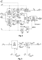
- Fig. 1 shows a block diagram for upmixing of the separate stems (or complementary components) and for superposition of the upmixed signals.
- x ( k ) ( t ) is a vector with the input channel data at time instant t and C is the number of input channels.
- M k denotes the metadata used in the upmix process for the k- th stem. These metadata were generated by human interaction in a studio.
- the output of each upmixing step or stage 11, 12 (for the k -th stem) consists of a signal vector y ch k t carrying a number C ch of channel objects and a signal vector y HOA k t carrying a HOA representation with 0 HOA coefficients.
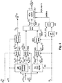
- FIG. 2 The processing of one individual stem k is shown in Fig. 2 .
- This processing, or a corresponding apparatus, can be used in a studio.
- a vector a is defined which contains the channel indices of the input signals to be used for the transport signals y ch k t of the channel objects.
- the number of elements in a is C ch .
- an index vector a ( k ) with C ch ( k ) elements is defined or provided that contains the channel indices of the input signal to be used for the channel objects in this stem.
- C ch ( k ) ⁇ C ch is the number of channel objects used in stem k . All indices from a ( k ) must be contained in a .
- each of the vectors a , a ( k ) , r (k) every channel index can occur only once.
- splitting step or stage 21 receives the input signal x ( k ) ( t ) .
- Step/stage 21 can be a demultiplexer. This operation results in a signal vector x ch k t with the channel objects and a second signal vector x rem k t which contains those channels from the input signal that are converted to HOA later in the processing chain.
- the zero channels adding step or stage 23 adds to signal vector x ⁇ ch k t zero values corresponding to channel indices that are contained in a , but not in a ( k ) .
- the channel object output y ch k t is extended to C ch channels.
- the decorrelated signals creating step or stage 24 creates additional signals from the input channels x ( k ) ( t ) for further spatial distribution.
- these additional signals are decorrelated signals from the original input channels in order to avoid comb filtering effects or phantom sources when these newly created signals are added to the sound field.
- a tuple X k T 1 k , ... , T C decorr k k
- step/stage 24 The creation of the decorrelated signals in step/stage 24 is shown in more detail in Fig. 3 .
- the vector ⁇ j k with the mix gains contains at one position the value 'one' and 'zero' elsewhere.
- ⁇ j 1 k ⁇ j 2 k and x decorrIn
- j 1 k t x decorrIn , j 2 k t .
- step or stage 32 the decorrelated signals are computed.
- a typical approach for the decorrelation of audio signals is described in [4], where for example a filter is applied to the input signal in order to change its phase while the sound impression is preserved by preserving the magnitude spectrum of the signal.
- Other approaches for the computation of decorrelated signals can be used instead.
- arbitrary impulse responses can be used that add reverberation to the signal and can change the magnitude spectrum of the signal.
- the configuration of each decorrelator is defined by f j k , which is an integer number specifying e.g. the set of filter coefficients to be used. If the decorrelator uses long finite impulse response filters, the filtering operation can be efficiently realised using fast convolution.
- the resulting signal x decorr , j k t is the output of step/stage 24 in Fig. 2 .
- the signals from the signal vectors x ⁇ rem k t and x ⁇ decorr k t are converted to HOA as general plane waves with individual directions of incidence.
- Step/stage 27 receives parameter N and positions (i.e. spatial positions for HOA conversion for remaining channels and decorrelated signals) from a second combining step or stage 29.
- the first C rem ( k ) elements are spatially positioned at the original channel directions as defined for the corresponding channels from input signal x ( k ) ( t ) .
- the choice of these directions influences the spatial distribution of the resulting 3D sound field. It is also possible to use time-varying spatial directions which are adapted to the audio content.
- ⁇ k : ⁇ ⁇ s ⁇ rem , 1 k s ⁇ rem , C rem k k s ⁇ 1 k ... s ⁇ C decorr k k ⁇ R O ⁇ C spat k , ⁇ >0 being an arbitrary positive real-valued scaling factor. This factor is chosen such that, after rendering, the loudness of the signals converted to HOA matches the loudness of objects.
- This HOA representation can directly be taken as the HOA transport signal, or a subsequent conversion to a so-called equivalent spatial domain representation can be applied.
- the latter representation is obtained by rendering the original HOA representation c ( k ) ( t ) (see section C for definition, in particular equation (31)) consisting of 0 HOA coefficient sequences to the same number 0 of virtual loudspeaker signals w j k t , 1 ⁇ j ⁇ 0 , representing general plane wave signals.
- the order-dependent directions of incidence ⁇ ⁇ j N , 1 ⁇ j ⁇ 0 may be represented as positions on the unit sphere (see also section C for the definition of the spherical coordinate system), on which they should be distributed as uniformly as possible (see e.g. [3] on the computation of specific directions).
- the advantage of this format is that the resulting signals have a value range of [-1,1] suited for a fixed-point representation. Thereby a control of the playback level is facilitated.
- the spatial distribution of the resulting 3D sound field is controlled.
- the loudness of the created mix should be the same as for the original channel-based input.
- a rendering of the transport signals (channel objects and HOA representation) to specific loudspeaker positions is required.
- These loudspeaker signals are typically used for a loudness analysis.
- the loudness matching to the original 2D audio signal could also be performed by the audio mixing artist when listening to the signals and adjusting the gain values.
- signal y HOA k t is rendered to loudspeakers, and signal y ch k t is added to the corresponding signals for these loudspeakers.
- Fig. 4 shows an alternative to the block diagram of Fig. 2 .
- the gain applying step or stage 45 in the lower signal path is moved towards the input.
- the gains are applied before the decorrelator step or stage 451 is used (all other steps or stages 41 to 43 and 46 to 49 correspond to the respective steps or stages 21 to 23 and 26 to 29 in Fig. 2 ).
- DAW digital audio workstation
- the input signals are mixed according to equation (11) in order to obtain C decorr ( k ) channels contained in the signal vector x decorrIn k t .
- C ch 4 channels are used, which are namely the front left/right/center channels and the LFE channel.
- the same number of channel objects is used for all stems.
- r ( k ) [5,6] T for 1 ⁇ k ⁇ K.
- the decorrelator 531 to 536 is applied with different filter settings to the individual input channels.
- the seventh decorrelator 57 is applied to a downmix of the input channels (except the LFE channel). This downmix is provided using multipliers or dividers 551 to 555 and a combiner 56.
- Table 3 shows for upmix to 3D example gain factors for all channels, which gain factors are applied in gain steps or stages 511-514, 521, 522, 541-546 and 58, respectively: gain symbol g ch , 1 k g ch , 2 k g ch , 3 k g ch , 4 k g rem , 1 k g rem , 2 k g 1 k g 2 k g 3 k g 4 k g 5 k g 6 k g 7 k value in dB -1.5 -1.5 -1.5 0 -1.5 -1.5 -7.5 -7.5 -1.5 -1.5 -1.5 -1.5 -1.5 -1.5 -1.5 -1.5 -1.5 -1.5 -1.5 -1.5 -1.5 -1.5 -1.5 -1.5 -1.5 -1.5 -1.5 -1.5 -1.5 -1.5 -1.5 -1.5 -1.5 -1.5 -1.5 -1.5 -
- the left/right surround channel signals are converted in step or stage 59 to HOA using the typical loudspeaker positions of these channels.
- L, R, L s , R s one decorrelated version is placed at an elevated position with a modified azimuth value compared to the original loudspeaker position in order to create a better envelopment.
- an additional decorrelated signal is placed in the 2D plane at the sides (azimuth angles ⁇ 90 degrees).
- the channel objects (except LFE ) and the surround channels converted to HOA are slightly attenuated.
- the original loudness is maintained by the additional sound objects placed in the 3D space.
- the decorrelated version of the downmix of all input channels except the LFE is placed for HOA conversion above the sweet spot.
- HOA Higher Order Ambisonics
- j n ( ⁇ ) denotes the spherical Bessel functions of the first kind and S n m ⁇ , ⁇ denotes the real valued Spherical Harmonics of order n and degree m , which are defined in section C.1.
- the expansion coefficients A n m k depend only on the angular wave number k . Note that it has been implicitly assumed that sound pressure is spatially band-limited. Thus the series is truncated with respect to the order index n at an upper limit N, which is called the order of the HOA representation.
- weights c n m t of the expansion are referred to as continuous-time HOA coefficient sequences and can be shown to always be real-valued.
- the position index of an HOA coefficient sequence c n m t within the vector c ( t ) is given by n ( n + 1) + 1 + m .
- a superposition of channel objects and HOA representations of separate stems can be used.
- Multiple decorrelated signals can be generated from multiple identical multi-channel 2D audio input signals x (k) (t) based on frequency domain processing, for example by fast convolution using an FFT or a filter bank.
- a frequency analysis of the common input signal is carried out only once and that frequency domain processing and is applied for each output channel separately.
- the described processing can be carried out by a single processor or electronic circuit, or by several processors or electronic circuits operating in parallel and/or operating on different parts of the complete processing.
- the instructions for operating the processor or the processors according to the described processing can be stored in one or more memories.
- the at least one processor is configured to carry out these instructions.
Description
- The invention relates to a method and to an apparatus for generating from a multi-channel 2D audio input signal a 3D sound representation signal which includes a HOA representation signal and channel object signals.
- Recently a new format for 3D audio has been standardised as MPEG-H 3D Audio [1], but only a small number of 3D audio content in this format is available. To easily generate much of such content it is desired to convert existing 2D content, like 5.1, to 3D content which contains sound also from elevated positions. This way, it is possible to create 3D content without completely remixing the sound from the original sound objects.
- Currently there is no simple and satisfying way to create 3D audio from existing 2D content. The conversion from 2D to 3D sound should spatially redistribute the sound from existing channels. Furthermore, this conversion (also called upmixing) should enable a mixing artist to control this process.
- There are a variety of representations of three-dimensional sound including channel-based approaches like 22.2, object based approaches and sound field oriented approaches like Higher Order Ambisonics (HOA). An HOA representation offers the advantage over channel based methods of being independent of a specific loudspeaker set-up and that its data amount is independent of the number of sound sources used. Thus, it is desired to use HOA as a format for transport and storage for this application.
- A problem to be solved by the invention is to create with improved quality 3D audio from existing 2D audio content. This problem is solved by the method disclosed in
claim 1. An apparatus that utilises this method is disclosed in claim 8. - Advantageous additional embodiments of the invention are disclosed in the respective dependent claims.
- The 3D audio format for transport and storage comprises channel objects and an HOA representation. The HOA representation is used for an improved spatial impression with added height information. The channel objects are signals taken from the original 2D channel-based content with fixed spatial positions. These channel objects can be used for emphasising specific directions, e.g. if a mixing artist wants to emphasise the frontal channels. The spatial positions of the channel objects may be given as spherical coordinates or as an index from a list of available loudspeaker positions. The number of channel objects is C ch ≤ C, where C is the number of channels of the channel-based input signal. If an LFE (low frequency effects) channel exists it can be used as one of the channel objects.
- For the HOA part, a representation of order N is used. This order determines the
number 0 of HOA coefficients by 0 = (N + 1)2. The HOA order affects the spatial resolution of the HOA representation, which improves with a growing order N. Typical HOA representations using order N = 4 consist of O = 25 HOA coefficient sequences. - The used signals (channel objects and HOA representation) can be data compressed in the MPEG-H 3D Audio format. The 3D audio scene can be rendered to the desired loudspeaker positions which allows playback on every type of loudspeaker setup.
- In principle, the inventive method according to
claim 1 is adapted for generating from a multi-channel 2D audio input signal a 3D sound representation which includes a HOA representation and channel object signals, wherein said 3D sound representation is suited for a presentation with loudspeakers after rendering said HOA representation and combination with said channel object signals, said method including: - generating each of said channel object signals by selecting and scaling one channel signal of said multi-channel 2D audio input signal;
- generating additional signals for placing them in the 3D space by scaling the remaining non-selected channels from said multi-channel 2D audio input signal and/or by decorrelating a scaled version of a mix of channels from said multi-channel 2D audio input signal, wherein spatial positions for said additional signals are predetermined;
- converting said additional signals to said HOA representation using the corresponding spatial positions.
- In principle the inventive apparatus according to claim 8 is adapted for generating from a multi-channel 2D audio input signal a 3D sound representation which includes a HOA representation and channel object signals, wherein said 3D sound representation is suited for a presentation with loudspeakers after rendering said HOA representation and combination with said channel object signals, said apparatus including means adapted to:
- generate each of said channel object signals by selecting and scaling one channel signal of said multi-channel 2D audio input signal;
- generate additional signals for placing them in the 3D space by scaling the remaining non-selected channels from said multi-channel 2D audio input signal and/or by decorrelating a scaled version of a mix of channels from said multi-channel 2D audio input signal, wherein spatial positions for said additional signals are predetermined;
- convert said additional signals to said HOA representation using the corresponding spatial positions.
- Exemplary embodiments of the invention are described with reference to the accompanying drawings, which show in:
- Fig. 1
- Upmix of multiple stems and superposition;
- Fig. 2
- Block diagram for upmixing of stem k (dashed lines indicate metadata);
- Fig. 3
- Block diagram for creation of decorrelated signals of stem k (dashed lines indicate metadata);
- Fig. 4
- Block diagram for upmixing of stem k with moved gains (dashed lines indicate metadata);
- Fig. 5
- Upmix example configuration for one stem;
- Fig. 6
- Spherical coordinate system.
- Even if not explicitly described, the following embodiments may be employed in any combination or sub-combination.
- For film productions typically three separate stems are available: dialogue, music and special sound effects. A stem in this context means a channel-based mix in the input format for one of these signal types. The channel-wise weighted sum of all stems builds the final mix for delivery in the original format.
- In general, it is assumed that the existing 2D content used as input signal (e.g. 5.1 surround) is available separately for each stem. Each of these stems indexed k = 1,...,K may have separate metadata for upmixing to 3D audio.
-
Fig. 1 shows a block diagram for upmixing of the separate stems (or complementary components) and for superposition of the upmixed signals. x (k)(t) is a vector with the input channel data at time instant t and C is the number of input channels. Thus, the c-th element of the vector contains one sample of the c-th input channel with c = 1,...,C. - Mk denotes the metadata used in the upmix process for the k-th stem. These metadata were generated by human interaction in a studio. The output of each upmixing step or
stage 11, 12 (for the k-th stem) consists of a signal vector

combiners 13, 14 by

- This kind of processing can also be applied in case no separate stems are available, i.e. K = 1. But with the different signal types available in separate stems the spatial distribution of the created 3D sound field can be controlled more flexible. To correctly render the audio scene on the playback side, the fixed positions of channel objects are stored, too.
- The processing of one individual stem k is shown in
Fig. 2 . This processing, or a corresponding apparatus, can be used in a studio. - The metadata Mk shown in
Fig. 1 are composed of
- The set


- Throughout this application small boldface letters are used as symbols for vectors. The same letter in non-boldface type, with a subscript integer index c, indicates the c-th element of that vector.
- Thus, the vector a is defined by a = [a1, a2,..., a C
ch ] T where (·) T denotes transposition. Each element of this vector must be one of the input channel numbers, i.e. ac ∈ I for c = 1,..., C ch. For each individual stem k an index vector a (k) with C ch(k) elements is defined or provided that contains the channel indices of the input signal to be used for the channel objects in this stem. Thus, C ch(k) ≤ C ch is the number of channel objects used in stem k. All indices from a (k) must be contained in a . This way it is possible to use a different number of channel objects in the different stems. All channel indices from I that are not contained in a (k) must be contained in the vector r (k) that contains the channel indices for the remaining channels. The number of elements in r (k) is
- In each of the vectors a , a (k) , r (k) every channel index can occur only once.
- In
Fig. 2 , splitting step orstage 21 receives the input signal x (k)(t). Using the a (k) data, splitting of the input signal x (k)(t) in two signals with C ch(k) and C rem(k) channels respectively is performed by object splitting. Step/stage 21 can be a demultiplexer. This operation results in a signal vector

- The metadata


stages 

- The zero channels adding step or
stage 23 adds to signal vector


- It is assumed that α and therefore also C ch are available as global information.
- The decorrelated signals creating step or
stage 24 creates additional signals from the input channels x (k)(t) for further spatial distribution. In general these additional signals are decorrelated signals from the original input channels in order to avoid comb filtering effects or phantom sources when these newly created signals are added to the sound field. For the parameterisation of these additional signals a tuple
- from the metadata is used. Xk contains for each additional signal j a tuple


- The creation of the decorrelated signals in step/
stage 24 is shown in more detail inFig. 3 . - In a mixer step or
stage 31 the input signals to the decorrelators are computed by mixing the input channels using the vectors


- In step or
stage 32 the decorrelated signals are computed. A typical approach for the decorrelation of audio signals is described in [4], where for example a filter is applied to the input signal in order to change its phase while the sound impression is preserved by preserving the magnitude spectrum of the signal. Other approaches for the computation of decorrelated signals can be used instead. For example, arbitrary impulse responses can be used that add reverberation to the signal and can change the magnitude spectrum of the signal. The configuration of each decorrelator is defined by
- The j-th element of the output vector

stage 32 is computed by


- The resulting signal

stage 24 inFig. 2 . In gain applying step orstage 25, all created additional (decorrelated) signals


- The signals from the signal vectors


stage 26, these signals are grouped into the signal vector

- I.e., basically the elements of the two vectors


- In HOA and spatial conversion step or
stage 27 for each element of
stage 27 also receives parameter N and positions (i.e. spatial positions for HOA conversion for remaining channels and decorrelated signals) from a second combining step orstage 29. Step orstage 28 extracts
stage 29 combines the positions

- In step/
stage 27, the first C rem(k) elements (elements taken from


- A mode vector dependent on direction Ω for HOA order N is defined by


- The HOA representation signal is then computed in step/
stage 27 by
- This HOA representation can directly be taken as the HOA transport signal, or a subsequent conversion to a so-called equivalent spatial domain representation can be applied. The latter representation is obtained by rendering the original HOA representation c (k)(t) (see section C for definition, in particular equation (31)) consisting of 0 HOA coefficient sequences to the
same number 0 of virtual loudspeaker signals

- Regarding the rendering process in detail, first all virtual loudspeaker signals are summarised in a vector as

- Denoting the scaled mode matrix with respect to the virtual directions


- Thus, dependent on the use of the conversion to the spatial domain representation, the output HOA transport signal is

- With the gain factors applied to the channel objects and signals converted to HOA as defined in equations (6), (7), (13), the spatial distribution of the resulting 3D sound field is controlled. In general, it is also possible to use time-varying gains in order to use a signal-adaptive spatial distribution. The loudness of the created mix should be the same as for the original channel-based input. For adjusting the gain values to get the desired effect, in general a rendering of the transport signals (channel objects and HOA representation) to specific loudspeaker positions is required. These loudspeaker signals are typically used for a loudness analysis. The loudness matching to the original 2D audio signal could also be performed by the audio mixing artist when listening to the signals and adjusting the gain values.
- In a subsequent processing in a studio, or at a receiver side, signal


-
Fig. 4 shows an alternative to the block diagram ofFig. 2 . The gain applying step orstage 45 in the lower signal path is moved towards the input. The gains are applied before the decorrelator step orstage 451 is used (all other steps or stages 41 to 43 and 46 to 49 correspond to the respective steps or stages 21 to 23 and 26 to 29 inFig. 2 ). This way, application of the gains inside a digital audio workstation (DAW) is possible in case the decorrelation and HOA conversion is not running inside the same DAW application. - First, the input signals are mixed according to equation (11) in order to obtain C decorr(k) channels contained in the signal vector


- Third, the resulting signals in

decorrelators 451 using the corresponding parameters (see also equation (12)):
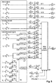
- In this section an exemplary configuration for the conversion of a 5.1 surround sound to 3D sound is considered. The signal flow for this example is shown in
Fig. 5 for one stem according toFig. 2 . In this example the number of input channels is C = 6, the input channel configuration is defined in the following Table 1:channel number channel name short name 1 front left L 2 front right R 3 front centre C 4 LFE LFE 5 left surround L S 6 right surround RS - For the channel objects C ch = 4 channels are used, which are namely the front left/right/center channels and the LFE channel. Thus, the vector with the input channel indices for the channel objects is a = [1,2,3,4] T . In this example, the same number of channel objects is used for all stems. Thus, a (k) = a = [1,2,3,4] T and r (k) = [5,6] T for 1 ≤ k ≤ K. With K = 3 stems this results in C ch(k) = C ch = 4 f or k ∈ {1,2,3}. The number of remaining channels is therefore C rem(k) = C - C ch(k) = 2. In the given example the number of decorrelated signals is C decorr(k) = 7. For the first six decorrelated signals the
decorrelator 531 to 536 is applied with different filter settings to the individual input channels. Theseventh decorrelator 57 is applied to a downmix of the input channels (except the LFE channel). This downmix is provided using multipliers ordividers 551 to 555 and acombiner 56. In this example the filter settings are
- The spatial directions used for the conversion to HOA are given in Table 2:
direction symbol 


azimuth φ in deg inclination θ in deg 115 90 -115 90 72 60 -72 60 90 90 144 60 


-90 90 -144 60 0 0 - Table 3 shows for upmix to 3D example gain factors for all channels, which gain factors are applied in gain steps or stages 511-514, 521, 522, 541-546 and 58, respectively:
gain symbol 


value in dB -1.5 -1.5 -1.5 0 -1.5 -1.5 -7.5 -7.5 -1.5 -1.5 -1.5 -1.5 -1.5 - In this example the left/right surround channel signals are converted in step or
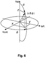
stage 59 to HOA using the typical loudspeaker positions of these channels. From each of the channels L, R, L s , R s one decorrelated version is placed at an elevated position with a modified azimuth value compared to the original loudspeaker position in order to create a better envelopment. From each of the left/right surround channels an additional decorrelated signal is placed in the 2D plane at the sides (azimuth angles ±90 degrees). The channel objects (except LFE) and the surround channels converted to HOA are slightly attenuated. The original loudness is maintained by the additional sound objects placed in the 3D space. The decorrelated version of the downmix of all input channels except the LFE is placed for HOA conversion above the sweet spot. - Higher Order Ambisonics (HOA) is based on the description of a sound field within a compact area of interest, which is assumed to be free of sound sources. In that case the spatio-temporal behaviour of the sound pressure p(t,x ) at time t and position x within the area of interest is physically fully determined by the homogeneous wave equation. In the following a spherical coordinate system is assumed as shown in
Fig. 6 . In this coordinate system the x axis points to the frontal position, the y axis points to the left, and the z axis points to the top. A position in space x = (r,θ,Φ) T is represented by a radius r ≥ 0 (i.e. the distance to the coordinate origin), an inclination angle θ ∈ [0,π] measured from the polar axis z and an azimuth angle φ ∈ [0,2π[ measured counter-clockwise in the x - y plane from the x axis. Further, (·) T denotes the transposition. - Then it can be shown (cf.[5]) that the Fourier transform of the sound pressure with respect to time denoted by, i.e.


- In equation (26), c s denotes the speed of sound and k denotes the angular wave number, which is related to the angular frequency ω by


- Since the area of interest (i.e. the sweet spot) is assumed to be free of sound sources, the sound field can be represented by a superposition of an infinite number of general plane waves arriving from all possible directions

 indicates the unit sphere in the three-dimensional space and p GPW(t, x , Ω ) denotes the contribution of the general plane wave from direction Ω to the pressure at time t and position x .
- Evaluating the contribution of each general plane wave to the pressure in the coordinate origin x ORIG = (0 0 0) T provides a time and direction dependent function


- The weights

- Collected in a single vector c(t) according to


- It should be noted that the knowledge of the continuous-time HOA coefficient sequences is theoretically sufficient for perfect reconstruction of the sound pressure within the area of interest, because it can be shown that their Fourier transforms with respect to time, i.e.


- The real valued spherical harmonics


- The associated Legendre functions P n,m(x) are defined as

- For a storage or transmission of the 3D sound representation signal a superposition of channel objects and HOA representations of separate stems can be used.
- Multiple decorrelated signals can be generated from multiple identical multi-channel 2D audio input signals x(k)(t) based on frequency domain processing, for example by fast convolution using an FFT or a filter bank. A frequency analysis of the common input signal is carried out only once and that frequency domain processing and is applied for each output channel separately.
- The described processing can be carried out by a single processor or electronic circuit, or by several processors or electronic circuits operating in parallel and/or operating on different parts of the complete processing.
The instructions for operating the processor or the processors according to the described processing can be stored in one or more memories. The at least one processor is configured to carry out these instructions. -
- [1] ISO/IEC JTC1/SC29/WG11 DIS 23008-3. Information technology - High efficiency coding and media delivery in heterogeneous environments - Part 3: 3D audio, July 2014.
- [2] J. Daniel, "Representation de champs acoustiques, application a la transmission et a la reproduction de scenes sonores complexes dans un contexte multimedia", PhD thesis,
- [3] J. Fliege, U. Maier, "A two-stage approach for computing cubature formulae for the sphere", Technical report, Fachbereich Mathematik, Universität Dortmund, 1999. Node numbers are found at http://www.mathematik.unidortmund.de/lsx/research/projects/fliege/nodes/nodes.html.
- [4] G.S. Kendall, "The decorrelation of audio signals and its impact on spatial imaginery", Computer Music Journal, vol.19, no.4, pp.71-87, 1995.
- [5] E.G. Williams, "Fourier Acoustics", Applied Mathematical Sciences, vol.93, Academic Press, 1999.
Claims (15)
- Method for generating from a multi-channel 2D audio input signal (x (k)(t)) a 3D sound representation which includes a HOA representation

 - generating (21, 221, 23; 41, 421, 43) each of said channel object signals
 - generating additional signals

 - converting (27; 47) said additional signals

- Method according to claim 1, wherein said spatial positions (29; 49) can vary over time and their number can vary over time.
- Method according to claim 1 or 2, wherein said scaling (221, 222, 25; 421, 422, 45) is carried out by applying gain factors which can vary over time.
- Method according to any of claims 1-3, wherein said scalings are adjusted such that said 3D sound representation can be rendered with the loudness of said multi-channel 2D audio input signal ( x (k)(t)).
- Method according to claim 3 or 4, wherein said gain factors are applied (45) before said decorrelating (451).
- Method according to any of claims 1-5, wherein the multi-channel 2D audio input signal ( x (k)(t)) is replaced by multiple multi-channel 2D audio input signals, each representing one complementary component of a mixed multi-channel 2D audio input signal, wherein each multi-channel 2D audio input signal is converted to an individual 3D sound representation signal using individual conversion parameters,
and wherein the individually created 3D sound representations are superposed to a final mixed 3D sound representation. - Method according to any of claims 1-6, wherein multiple decorrelated signals are generated from one channel signal, or a mix of channel signals, of the multi-channel 2D audio input signals (x (k)(t)) based on frequency domain processing, for example by fast convolution using an FFT or a filter bank, and a frequency analysis of the common input signal is carried out only once and said frequency domain processing and frequency synthesis is applied for each output channel separately.
- Apparatus for generating from a multi-channel 2D audio input signal ( x (k)(t)) a 3D sound representation which includes a HOA representation

 - generate (21, 221, 23; 41, 421, 43) each of said channel object signals
 - generate additional signals

 - convert (27; 47) said additional signals

- Apparatus according to claim 8, wherein said spatial positions (29; 49) can vary over time and their number can vary over time.
- Apparatus according to claim 8 or 9, wherein said scaling (221, 222, 25; 421, 422, 45) is carried out by applying gain factors which can vary over time.
- Apparatus according to any of claims 8-10, wherein said scaling are adjusted such that said 3D sound representation can be rendered with the loudness of said multi-channel 2D audio input signal ( x (k)(t)).
- Apparatus according to claim 10 or 11, wherein said gain factors are applied (45) before said decorrelating (451).
- Apparatus according to any of claims 8-12, wherein the multi-channel 2D audio input signal ( x (k)(t)) is replaced by multiple multi-channel 2D audio input signals, each representing one complementary component of a mixed multi-channel 2D audio input signal, and wherein each multi-channel 2D audio input signal is converted to an individual 3D sound representation signal using individual conversion parameters,
and wherein the individually created 3D sound representations are superposed to a final mixed 3D sound representation. - Apparatus according to any of claims 8-13, wherein multiple decorrelated signals are generated from one channel signal, or a mix of channel signals, of the multi-channel 2D audio input signals ( x (k)(t)) based on frequency domain processing, for example by fast convolution using an FFT or a filter bank, and a frequency analysis of the common input signal is carried out only once and said frequency domain processing and frequency synthesis is applied for each output channel separately.
- Computer program product comprising instructions which,
when carried out on a computer, perform the method according to any of claims 1-7.
Applications Claiming Priority (2)
| Application Number | Priority Date | Filing Date | Title |
|---|---|---|---|
| EP15306796 | 2015-11-13 | ||
| PCT/EP2016/077382 WO2017081222A1 (en) | 2015-11-13 | 2016-11-11 | Method and apparatus for generating from a multi-channel 2d audio input signal a 3d sound representation signal |
Publications (2)
| Publication Number | Publication Date |
|---|---|
| EP3375208A1 EP3375208A1 (en) | 2018-09-19 |
| EP3375208B1 true EP3375208B1 (en) | 2019-11-06 |
Family
ID=54548123
Family Applications (1)
| Application Number | Title | Priority Date | Filing Date |
|---|---|---|---|
| EP16794347.1A Active EP3375208B1 (en) | 2015-11-13 | 2016-11-11 | Method and apparatus for generating from a multi-channel 2d audio input signal a 3d sound representation signal |
Country Status (3)
| Country | Link |
|---|---|
| US (1) | US10341802B2 (en) |
| EP (1) | EP3375208B1 (en) |
| WO (1) | WO2017081222A1 (en) |
Families Citing this family (2)
| Publication number | Priority date | Publication date | Assignee | Title |
|---|---|---|---|---|
| US10037750B2 (en) * | 2016-02-17 | 2018-07-31 | RMXHTZ, Inc. | Systems and methods for analyzing components of audio tracks |
| US11341952B2 (en) | 2019-08-06 | 2022-05-24 | Insoundz, Ltd. | System and method for generating audio featuring spatial representations of sound sources |
Family Cites Families (6)
| Publication number | Priority date | Publication date | Assignee | Title |
|---|---|---|---|---|
| EP2469741A1 (en) * | 2010-12-21 | 2012-06-27 | Thomson Licensing | Method and apparatus for encoding and decoding successive frames of an ambisonics representation of a 2- or 3-dimensional sound field |
| EP2700250B1 (en) | 2011-04-18 | 2015-03-04 | Dolby Laboratories Licensing Corporation | Method and system for upmixing audio to generate 3d audio |
| WO2013108200A1 (en) | 2012-01-19 | 2013-07-25 | Koninklijke Philips N.V. | Spatial audio rendering and encoding |
| EP2645748A1 (en) * | 2012-03-28 | 2013-10-02 | Thomson Licensing | Method and apparatus for decoding stereo loudspeaker signals from a higher-order Ambisonics audio signal |
| EP2866475A1 (en) * | 2013-10-23 | 2015-04-29 | Thomson Licensing | Method for and apparatus for decoding an audio soundfield representation for audio playback using 2D setups |
| EP3357259B1 (en) * | 2015-09-30 | 2020-09-23 | Dolby International AB | Method and apparatus for generating 3d audio content from two-channel stereo content |
-
2016
- 2016-11-11 EP EP16794347.1A patent/EP3375208B1/en active Active
- 2016-11-11 WO PCT/EP2016/077382 patent/WO2017081222A1/en active Application Filing
- 2016-11-11 US US15/768,695 patent/US10341802B2/en active Active
Non-Patent Citations (1)
| Title |
|---|
| None * |
Also Published As
| Publication number | Publication date |
|---|---|
| EP3375208A1 (en) | 2018-09-19 |
| US10341802B2 (en) | 2019-07-02 |
| US20190069115A1 (en) | 2019-02-28 |
| WO2017081222A1 (en) | 2017-05-18 |
Similar Documents
| Publication | Publication Date | Title |
|---|---|---|
| EP3629605B1 (en) | Method and device for rendering an audio soundfield representation | |
| US20170358308A1 (en) | Sound system | |
| EP3860154B1 (en) | Method for decoding a compressed hoa dataframe representation of a sound field. | |
| TWI444989B (en) | Using multichannel decorrelation for improved multichannel upmixing | |
| EP2976769B1 (en) | Method and apparatus for enhancing directivity of a 1st order ambisonics signal | |
| EP2285139A2 (en) | Device and method for converting spatial audio signal | |
| EP3162087B1 (en) | Coded hoa data frame representation that includes non-differential gain values associated with channel signals of specific ones of the data frames of an hoa data frame representation | |
| JP6378432B2 (en) | Method and apparatus for low bit rate compression of high-order ambisonics HOA signal representation of sound field | |
| EP3161820B1 (en) | Method and apparatus for determining for the compression of an hoa data frame representation a lowest integer number of bits required for representing non-differential gain values | |
| EP3329486B1 (en) | Method and apparatus for generating from an hoa signal representation a mezzanine hoa signal representation | |
| EP3375208B1 (en) | Method and apparatus for generating from a multi-channel 2d audio input signal a 3d sound representation signal | |
| EP3329485B1 (en) | System and method for spatial processing of soundfield signals | |
| EP3161821B1 (en) | Method for determining for the compression of an hoa data frame representation a lowest integer number of bits required for representing non-differential gain values | |
| US11942097B2 (en) | Multichannel audio encode and decode using directional metadata | |
| Kraft et al. | Low-complexity stereo signal decomposition and source separation for application in stereo to 3D upmixing | |
| US20230025801A1 (en) | Colorless generation of elevation perceptual cues using all-pass filter networks | |
| Cobos et al. | Interactive enhancement of stereo recordings using time-frequency selective panning | |
| WO2023118078A1 (en) | Multi channel audio processing for upmixing/remixing/downmixing applications |
Legal Events
| Date | Code | Title | Description |
|---|---|---|---|
| STAA | Information on the status of an ep patent application or granted ep patent |
Free format text: STATUS: UNKNOWN |
|
| STAA | Information on the status of an ep patent application or granted ep patent |
Free format text: STATUS: THE INTERNATIONAL PUBLICATION HAS BEEN MADE |
|
| PUAI | Public reference made under article 153(3) epc to a published international application that has entered the european phase |
Free format text: ORIGINAL CODE: 0009012 |
|
| STAA | Information on the status of an ep patent application or granted ep patent |
Free format text: STATUS: REQUEST FOR EXAMINATION WAS MADE |
|
| 17P | Request for examination filed |
Effective date: 20180613 |
|
| AK | Designated contracting states |
Kind code of ref document: A1 Designated state(s): AL AT BE BG CH CY CZ DE DK EE ES FI FR GB GR HR HU IE IS IT LI LT LU LV MC MK MT NL NO PL PT RO RS SE SI SK SM TR |
|
| AX | Request for extension of the european patent |
Extension state: BA ME |
|
| DAV | Request for validation of the european patent (deleted) | ||
| DAX | Request for extension of the european patent (deleted) | ||
| REG | Reference to a national code |
Ref country code: DE Ref legal event code: R079 Ref document number: 602016023959 Country of ref document: DE Free format text: PREVIOUS MAIN CLASS: H04S0007000000 Ipc: H04S0003000000 |
|
| RIC1 | Information provided on ipc code assigned before grant |
Ipc: H04S 7/00 20060101ALI20190514BHEP Ipc: H04S 3/00 20060101AFI20190514BHEP |
|
| GRAP | Despatch of communication of intention to grant a patent |
Free format text: ORIGINAL CODE: EPIDOSNIGR1 |
|
| STAA | Information on the status of an ep patent application or granted ep patent |
Free format text: STATUS: GRANT OF PATENT IS INTENDED |
|
| INTG | Intention to grant announced |
Effective date: 20190625 |
|
| GRAS | Grant fee paid |
Free format text: ORIGINAL CODE: EPIDOSNIGR3 |
|
| GRAA | (expected) grant |
Free format text: ORIGINAL CODE: 0009210 |
|
| STAA | Information on the status of an ep patent application or granted ep patent |
Free format text: STATUS: THE PATENT HAS BEEN GRANTED |
|
| AK | Designated contracting states |
Kind code of ref document: B1 Designated state(s): AL AT BE BG CH CY CZ DE DK EE ES FI FR GB GR HR HU IE IS IT LI LT LU LV MC MK MT NL NO PL PT RO RS SE SI SK SM TR |
|
| REG | Reference to a national code |
Ref country code: GB Ref legal event code: FG4D |
|
| REG | Reference to a national code |
Ref country code: CH Ref legal event code: EP Ref country code: AT Ref legal event code: REF Ref document number: 1200516 Country of ref document: AT Kind code of ref document: T Effective date: 20191115 |
|
| REG | Reference to a national code |
Ref country code: IE Ref legal event code: FG4D |
|
| REG | Reference to a national code |
Ref country code: DE Ref legal event code: R096 Ref document number: 602016023959 Country of ref document: DE |
|
| REG | Reference to a national code |
Ref country code: NL Ref legal event code: MP Effective date: 20191106 |
|
| REG | Reference to a national code |
Ref country code: LT Ref legal event code: MG4D |
|
| PG25 | Lapsed in a contracting state [announced via postgrant information from national office to epo] |
Ref country code: FI Free format text: LAPSE BECAUSE OF FAILURE TO SUBMIT A TRANSLATION OF THE DESCRIPTION OR TO PAY THE FEE WITHIN THE PRESCRIBED TIME-LIMIT Effective date: 20191106 Ref country code: NO Free format text: LAPSE BECAUSE OF FAILURE TO SUBMIT A TRANSLATION OF THE DESCRIPTION OR TO PAY THE FEE WITHIN THE PRESCRIBED TIME-LIMIT Effective date: 20200206 Ref country code: GR Free format text: LAPSE BECAUSE OF FAILURE TO SUBMIT A TRANSLATION OF THE DESCRIPTION OR TO PAY THE FEE WITHIN THE PRESCRIBED TIME-LIMIT Effective date: 20200207 Ref country code: BG Free format text: LAPSE BECAUSE OF FAILURE TO SUBMIT A TRANSLATION OF THE DESCRIPTION OR TO PAY THE FEE WITHIN THE PRESCRIBED TIME-LIMIT Effective date: 20200206 Ref country code: SE Free format text: LAPSE BECAUSE OF FAILURE TO SUBMIT A TRANSLATION OF THE DESCRIPTION OR TO PAY THE FEE WITHIN THE PRESCRIBED TIME-LIMIT Effective date: 20191106 Ref country code: LV Free format text: LAPSE BECAUSE OF FAILURE TO SUBMIT A TRANSLATION OF THE DESCRIPTION OR TO PAY THE FEE WITHIN THE PRESCRIBED TIME-LIMIT Effective date: 20191106 Ref country code: PT Free format text: LAPSE BECAUSE OF FAILURE TO SUBMIT A TRANSLATION OF THE DESCRIPTION OR TO PAY THE FEE WITHIN THE PRESCRIBED TIME-LIMIT Effective date: 20200306 Ref country code: PL Free format text: LAPSE BECAUSE OF FAILURE TO SUBMIT A TRANSLATION OF THE DESCRIPTION OR TO PAY THE FEE WITHIN THE PRESCRIBED TIME-LIMIT Effective date: 20191106 Ref country code: LT Free format text: LAPSE BECAUSE OF FAILURE TO SUBMIT A TRANSLATION OF THE DESCRIPTION OR TO PAY THE FEE WITHIN THE PRESCRIBED TIME-LIMIT Effective date: 20191106 Ref country code: NL Free format text: LAPSE BECAUSE OF FAILURE TO SUBMIT A TRANSLATION OF THE DESCRIPTION OR TO PAY THE FEE WITHIN THE PRESCRIBED TIME-LIMIT Effective date: 20191106 |
|
| PG25 | Lapsed in a contracting state [announced via postgrant information from national office to epo] |
Ref country code: IS Free format text: LAPSE BECAUSE OF FAILURE TO SUBMIT A TRANSLATION OF THE DESCRIPTION OR TO PAY THE FEE WITHIN THE PRESCRIBED TIME-LIMIT Effective date: 20200306 Ref country code: HR Free format text: LAPSE BECAUSE OF FAILURE TO SUBMIT A TRANSLATION OF THE DESCRIPTION OR TO PAY THE FEE WITHIN THE PRESCRIBED TIME-LIMIT Effective date: 20191106 Ref country code: RS Free format text: LAPSE BECAUSE OF FAILURE TO SUBMIT A TRANSLATION OF THE DESCRIPTION OR TO PAY THE FEE WITHIN THE PRESCRIBED TIME-LIMIT Effective date: 20191106 |
|
| PG25 | Lapsed in a contracting state [announced via postgrant information from national office to epo] |
Ref country code: AL Free format text: LAPSE BECAUSE OF FAILURE TO SUBMIT A TRANSLATION OF THE DESCRIPTION OR TO PAY THE FEE WITHIN THE PRESCRIBED TIME-LIMIT Effective date: 20191106 |
|
| REG | Reference to a national code |
Ref country code: CH Ref legal event code: PL |
|
| PG25 | Lapsed in a contracting state [announced via postgrant information from national office to epo] |
Ref country code: CH Free format text: LAPSE BECAUSE OF NON-PAYMENT OF DUE FEES Effective date: 20191130 Ref country code: LU Free format text: LAPSE BECAUSE OF NON-PAYMENT OF DUE FEES Effective date: 20191111 Ref country code: ES Free format text: LAPSE BECAUSE OF FAILURE TO SUBMIT A TRANSLATION OF THE DESCRIPTION OR TO PAY THE FEE WITHIN THE PRESCRIBED TIME-LIMIT Effective date: 20191106 Ref country code: DK Free format text: LAPSE BECAUSE OF FAILURE TO SUBMIT A TRANSLATION OF THE DESCRIPTION OR TO PAY THE FEE WITHIN THE PRESCRIBED TIME-LIMIT Effective date: 20191106 Ref country code: LI Free format text: LAPSE BECAUSE OF NON-PAYMENT OF DUE FEES Effective date: 20191130 Ref country code: EE Free format text: LAPSE BECAUSE OF FAILURE TO SUBMIT A TRANSLATION OF THE DESCRIPTION OR TO PAY THE FEE WITHIN THE PRESCRIBED TIME-LIMIT Effective date: 20191106 Ref country code: RO Free format text: LAPSE BECAUSE OF FAILURE TO SUBMIT A TRANSLATION OF THE DESCRIPTION OR TO PAY THE FEE WITHIN THE PRESCRIBED TIME-LIMIT Effective date: 20191106 Ref country code: CZ Free format text: LAPSE BECAUSE OF FAILURE TO SUBMIT A TRANSLATION OF THE DESCRIPTION OR TO PAY THE FEE WITHIN THE PRESCRIBED TIME-LIMIT Effective date: 20191106 |
|
| REG | Reference to a national code |
Ref country code: DE Ref legal event code: R097 Ref document number: 602016023959 Country of ref document: DE |
|
| REG | Reference to a national code |
Ref country code: AT Ref legal event code: MK05 Ref document number: 1200516 Country of ref document: AT Kind code of ref document: T Effective date: 20191106 |
|
| REG | Reference to a national code |
Ref country code: BE Ref legal event code: MM Effective date: 20191130 |
|
| PG25 | Lapsed in a contracting state [announced via postgrant information from national office to epo] |
Ref country code: SM Free format text: LAPSE BECAUSE OF FAILURE TO SUBMIT A TRANSLATION OF THE DESCRIPTION OR TO PAY THE FEE WITHIN THE PRESCRIBED TIME-LIMIT Effective date: 20191106 Ref country code: SK Free format text: LAPSE BECAUSE OF FAILURE TO SUBMIT A TRANSLATION OF THE DESCRIPTION OR TO PAY THE FEE WITHIN THE PRESCRIBED TIME-LIMIT Effective date: 20191106 Ref country code: MC Free format text: LAPSE BECAUSE OF FAILURE TO SUBMIT A TRANSLATION OF THE DESCRIPTION OR TO PAY THE FEE WITHIN THE PRESCRIBED TIME-LIMIT Effective date: 20191106 |
|
| PLBE | No opposition filed within time limit |
Free format text: ORIGINAL CODE: 0009261 |
|
| STAA | Information on the status of an ep patent application or granted ep patent |
Free format text: STATUS: NO OPPOSITION FILED WITHIN TIME LIMIT |
|
| 26N | No opposition filed |
Effective date: 20200807 |
|
| PG25 | Lapsed in a contracting state [announced via postgrant information from national office to epo] |
Ref country code: IE Free format text: LAPSE BECAUSE OF NON-PAYMENT OF DUE FEES Effective date: 20191111 |
|
| PG25 | Lapsed in a contracting state [announced via postgrant information from national office to epo] |
Ref country code: AT Free format text: LAPSE BECAUSE OF FAILURE TO SUBMIT A TRANSLATION OF THE DESCRIPTION OR TO PAY THE FEE WITHIN THE PRESCRIBED TIME-LIMIT Effective date: 20191106 Ref country code: SI Free format text: LAPSE BECAUSE OF FAILURE TO SUBMIT A TRANSLATION OF THE DESCRIPTION OR TO PAY THE FEE WITHIN THE PRESCRIBED TIME-LIMIT Effective date: 20191106 Ref country code: BE Free format text: LAPSE BECAUSE OF NON-PAYMENT OF DUE FEES Effective date: 20191130 |
|
| PG25 | Lapsed in a contracting state [announced via postgrant information from national office to epo] |
Ref country code: IT Free format text: LAPSE BECAUSE OF FAILURE TO SUBMIT A TRANSLATION OF THE DESCRIPTION OR TO PAY THE FEE WITHIN THE PRESCRIBED TIME-LIMIT Effective date: 20191106 |
|
| PG25 | Lapsed in a contracting state [announced via postgrant information from national office to epo] |
Ref country code: CY Free format text: LAPSE BECAUSE OF FAILURE TO SUBMIT A TRANSLATION OF THE DESCRIPTION OR TO PAY THE FEE WITHIN THE PRESCRIBED TIME-LIMIT Effective date: 20191106 |
|
| PG25 | Lapsed in a contracting state [announced via postgrant information from national office to epo] |
Ref country code: HU Free format text: LAPSE BECAUSE OF FAILURE TO SUBMIT A TRANSLATION OF THE DESCRIPTION OR TO PAY THE FEE WITHIN THE PRESCRIBED TIME-LIMIT; INVALID AB INITIO Effective date: 20161111 Ref country code: MT Free format text: LAPSE BECAUSE OF FAILURE TO SUBMIT A TRANSLATION OF THE DESCRIPTION OR TO PAY THE FEE WITHIN THE PRESCRIBED TIME-LIMIT Effective date: 20191106 |
|
| PG25 | Lapsed in a contracting state [announced via postgrant information from national office to epo] |
Ref country code: TR Free format text: LAPSE BECAUSE OF FAILURE TO SUBMIT A TRANSLATION OF THE DESCRIPTION OR TO PAY THE FEE WITHIN THE PRESCRIBED TIME-LIMIT Effective date: 20191106 |
|
| PG25 | Lapsed in a contracting state [announced via postgrant information from national office to epo] |
Ref country code: MK Free format text: LAPSE BECAUSE OF FAILURE TO SUBMIT A TRANSLATION OF THE DESCRIPTION OR TO PAY THE FEE WITHIN THE PRESCRIBED TIME-LIMIT Effective date: 20191106 |
|
| REG | Reference to a national code |
Ref country code: DE Ref legal event code: R081 Ref document number: 602016023959 Country of ref document: DE Owner name: DOLBY INTERNATIONAL AB, IE Free format text: FORMER OWNER: DOLBY INTERNATIONAL AB, AMSTERDAM ZUIDOOST, NL Ref country code: DE Ref legal event code: R081 Ref document number: 602016023959 Country of ref document: DE Owner name: DOLBY INTERNATIONAL AB, NL Free format text: FORMER OWNER: DOLBY INTERNATIONAL AB, AMSTERDAM ZUIDOOST, NL |
|
| REG | Reference to a national code |
Ref country code: DE Ref legal event code: R081 Ref document number: 602016023959 Country of ref document: DE Owner name: DOLBY INTERNATIONAL AB, IE Free format text: FORMER OWNER: DOLBY INTERNATIONAL AB, DP AMSTERDAM, NL |
|
| P01 | Opt-out of the competence of the unified patent court (upc) registered |
Effective date: 20230512 |
|
| PGFP | Annual fee paid to national office [announced via postgrant information from national office to epo] |
Ref country code: GB Payment date: 20231019 Year of fee payment: 8 |
|
| PGFP | Annual fee paid to national office [announced via postgrant information from national office to epo] |
Ref country code: FR Payment date: 20231019 Year of fee payment: 8 Ref country code: DE Payment date: 20231019 Year of fee payment: 8 |