EP3374758B1 - Systeme und verfahren zur identifizierung biologischer materialien - Google Patents
Systeme und verfahren zur identifizierung biologischer materialien Download PDFInfo
- Publication number
- EP3374758B1 EP3374758B1 EP16857048.9A EP16857048A EP3374758B1 EP 3374758 B1 EP3374758 B1 EP 3374758B1 EP 16857048 A EP16857048 A EP 16857048A EP 3374758 B1 EP3374758 B1 EP 3374758B1
- Authority
- EP
- European Patent Office
- Prior art keywords
- biological material
- cells
- plasmonic
- phase
- waves
- Prior art date
- Legal status (The legal status is an assumption and is not a legal conclusion. Google has not performed a legal analysis and makes no representation as to the accuracy of the status listed.)
- Active
Links
Images










Classifications
-
- H—ELECTRICITY
- H10—SEMICONDUCTOR DEVICES; ELECTRIC SOLID-STATE DEVICES NOT OTHERWISE PROVIDED FOR
- H10P—GENERIC PROCESSES OR APPARATUS FOR THE MANUFACTURE OR TREATMENT OF DEVICES COVERED BY CLASS H10
- H10P95/00—Generic processes or apparatus for manufacture or treatments not covered by the other groups of this subclass
-
- A—HUMAN NECESSITIES
- A61—MEDICAL OR VETERINARY SCIENCE; HYGIENE
- A61B—DIAGNOSIS; SURGERY; IDENTIFICATION
- A61B5/00—Measuring for diagnostic purposes; Identification of persons
- A61B5/0059—Measuring for diagnostic purposes; Identification of persons using light, e.g. diagnosis by transillumination, diascopy, fluorescence
- A61B5/0062—Arrangements for scanning
- A61B5/0066—Optical coherence imaging
-
- A—HUMAN NECESSITIES
- A61—MEDICAL OR VETERINARY SCIENCE; HYGIENE
- A61B—DIAGNOSIS; SURGERY; IDENTIFICATION
- A61B5/00—Measuring for diagnostic purposes; Identification of persons
- A61B5/0059—Measuring for diagnostic purposes; Identification of persons using light, e.g. diagnosis by transillumination, diascopy, fluorescence
- A61B5/0082—Measuring for diagnostic purposes; Identification of persons using light, e.g. diagnosis by transillumination, diascopy, fluorescence adapted for particular medical purposes
- A61B5/0084—Measuring for diagnostic purposes; Identification of persons using light, e.g. diagnosis by transillumination, diascopy, fluorescence adapted for particular medical purposes for introduction into the body, e.g. by catheters
-
- A—HUMAN NECESSITIES
- A61—MEDICAL OR VETERINARY SCIENCE; HYGIENE
- A61B—DIAGNOSIS; SURGERY; IDENTIFICATION
- A61B5/00—Measuring for diagnostic purposes; Identification of persons
- A61B5/44—Detecting, measuring or recording for evaluating the integumentary system, e.g. skin, hair or nails
- A61B5/441—Skin evaluation, e.g. for skin disorder diagnosis
-
- A—HUMAN NECESSITIES
- A61—MEDICAL OR VETERINARY SCIENCE; HYGIENE
- A61N—ELECTROTHERAPY; MAGNETOTHERAPY; RADIATION THERAPY; ULTRASOUND THERAPY
- A61N5/00—Radiation therapy
- A61N5/06—Radiation therapy using light
- A61N5/0601—Apparatus for use inside the body
-
- A—HUMAN NECESSITIES
- A61—MEDICAL OR VETERINARY SCIENCE; HYGIENE
- A61N—ELECTROTHERAPY; MAGNETOTHERAPY; RADIATION THERAPY; ULTRASOUND THERAPY
- A61N5/00—Radiation therapy
- A61N5/06—Radiation therapy using light
- A61N5/0613—Apparatus adapted for a specific treatment
- A61N5/062—Photodynamic therapy, i.e. excitation of an agent
-
- A—HUMAN NECESSITIES
- A61—MEDICAL OR VETERINARY SCIENCE; HYGIENE
- A61N—ELECTROTHERAPY; MAGNETOTHERAPY; RADIATION THERAPY; ULTRASOUND THERAPY
- A61N5/00—Radiation therapy
- A61N5/06—Radiation therapy using light
- A61N5/0613—Apparatus adapted for a specific treatment
- A61N5/0625—Warming the body, e.g. hyperthermia treatment
-
- B—PERFORMING OPERATIONS; TRANSPORTING
- B82—NANOTECHNOLOGY
- B82Y—SPECIFIC USES OR APPLICATIONS OF NANOSTRUCTURES; MEASUREMENT OR ANALYSIS OF NANOSTRUCTURES; MANUFACTURE OR TREATMENT OF NANOSTRUCTURES
- B82Y30/00—Nanotechnology for materials or surface science, e.g. nanocomposites
-
- G—PHYSICS
- G01—MEASURING; TESTING
- G01N—INVESTIGATING OR ANALYSING MATERIALS BY DETERMINING THEIR CHEMICAL OR PHYSICAL PROPERTIES
- G01N21/00—Investigating or analysing materials by the use of optical means, i.e. using sub-millimetre waves, infrared, visible or ultraviolet light
- G01N21/17—Systems in which incident light is modified in accordance with the properties of the material investigated
- G01N21/47—Scattering, i.e. diffuse reflection
- G01N21/49—Scattering, i.e. diffuse reflection within a body or fluid
-
- G—PHYSICS
- G01—MEASURING; TESTING
- G01N—INVESTIGATING OR ANALYSING MATERIALS BY DETERMINING THEIR CHEMICAL OR PHYSICAL PROPERTIES
- G01N21/00—Investigating or analysing materials by the use of optical means, i.e. using sub-millimetre waves, infrared, visible or ultraviolet light
- G01N21/17—Systems in which incident light is modified in accordance with the properties of the material investigated
- G01N21/55—Specular reflectivity
- G01N21/552—Attenuated total reflection
- G01N21/553—Attenuated total reflection and using surface plasmons
- G01N21/554—Attenuated total reflection and using surface plasmons detecting the surface plasmon resonance of nanostructured metals, e.g. localised surface plasmon resonance
-
- G—PHYSICS
- G02—OPTICS
- G02B—OPTICAL ELEMENTS, SYSTEMS OR APPARATUS
- G02B5/00—Optical elements other than lenses
- G02B5/008—Surface plasmon devices
-
- A—HUMAN NECESSITIES
- A61—MEDICAL OR VETERINARY SCIENCE; HYGIENE
- A61N—ELECTROTHERAPY; MAGNETOTHERAPY; RADIATION THERAPY; ULTRASOUND THERAPY
- A61N5/00—Radiation therapy
- A61N5/06—Radiation therapy using light
- A61N2005/0632—Constructional aspects of the apparatus
-
- A—HUMAN NECESSITIES
- A61—MEDICAL OR VETERINARY SCIENCE; HYGIENE
- A61N—ELECTROTHERAPY; MAGNETOTHERAPY; RADIATION THERAPY; ULTRASOUND THERAPY
- A61N5/00—Radiation therapy
- A61N5/06—Radiation therapy using light
- A61N2005/0658—Radiation therapy using light characterised by the wavelength of light used
- A61N2005/0659—Radiation therapy using light characterised by the wavelength of light used infrared
-
- A—HUMAN NECESSITIES
- A61—MEDICAL OR VETERINARY SCIENCE; HYGIENE
- A61N—ELECTROTHERAPY; MAGNETOTHERAPY; RADIATION THERAPY; ULTRASOUND THERAPY
- A61N5/00—Radiation therapy
- A61N5/06—Radiation therapy using light
- A61N2005/0658—Radiation therapy using light characterised by the wavelength of light used
- A61N2005/0662—Visible light
-
- A—HUMAN NECESSITIES
- A61—MEDICAL OR VETERINARY SCIENCE; HYGIENE
- A61N—ELECTROTHERAPY; MAGNETOTHERAPY; RADIATION THERAPY; ULTRASOUND THERAPY
- A61N5/00—Radiation therapy
- A61N5/06—Radiation therapy using light
- A61N2005/0658—Radiation therapy using light characterised by the wavelength of light used
- A61N2005/0662—Visible light
- A61N2005/0663—Coloured light
-
- A—HUMAN NECESSITIES
- A61—MEDICAL OR VETERINARY SCIENCE; HYGIENE
- A61N—ELECTROTHERAPY; MAGNETOTHERAPY; RADIATION THERAPY; ULTRASOUND THERAPY
- A61N5/00—Radiation therapy
- A61N5/06—Radiation therapy using light
- A61N5/067—Radiation therapy using light using laser light
-
- G—PHYSICS
- G01—MEASURING; TESTING
- G01N—INVESTIGATING OR ANALYSING MATERIALS BY DETERMINING THEIR CHEMICAL OR PHYSICAL PROPERTIES
- G01N2201/00—Features of devices classified in G01N21/00
- G01N2201/06—Illumination; Optics
- G01N2201/061—Sources
- G01N2201/06113—Coherent sources; lasers
Definitions
- the present invention relates to a system for identifying biological materials, including cells and tissues, and to a method of using the system in diagnostics. More particularly, the present invention relates to a system capable of identifying and characterizing biological material based on a plasmon/plasmon-polariton signature thereof.
- Electromagnetic fields are commonly used in medicine for diagnosis and therapy.
- One emerging EMF technology that has potential medical applications is plasmonics.
- Plasmonics is the study of the interaction between an electromagnetic field and free electrons in a metal. Most applications of plasmonics to date have relied on the interaction of light with the metallic structures, followed by detection of the light at the same wavelength that is reflected or scattered from the structures. For example, the optical excitation of surface plasmons in metal nanoparticles has led to the emerging field known as molecular plasmonics. Recent advances in molecular plasmonics and nanofabrication techniques have enabled novel optical materials and devices with applications in biology and nanomedicine.
- Gomez Rivas et al. (EP 2 133 688 A1 ) describe a metal nanoantenna for use in biosensing, which is arranged to exhibit at least two particle plasmon resonances or surface plasmon resonances which allows the use in a sensor for detection of low concentration biological components.
- the nanoantenna in this invention can have an asymmetric structural configuration and spectrally separated resonances.
- Kawamura et al. (US 8,515,508 B2 ) claim a method for measuring concentration of a biological substance contained in a living body in which deterioration of the accuracy due to the reflected light and the interruption component is suppressed.
- Linear-polarised light is emitted to a particle chip implemented in the skin, which generates a surface enhances Raman scattering light which changes the polarisation direction to obtain generate a signal.
- Rothberg et al. (US 2015/0177150 A1 ) describe an apparatus and methods for analysing single molecule and performing nucleic acid sequencing.
- the claimed apparatus contains an assay chip including multiple pixels with sample wells which are configured to receive a sample which emits emission energy upon excitement. The emitted emission energy is directed in a particular direction through a refractive lens.
- the present invention provides a system which is capable of identifying and typing biological material via plasmon/plasmon-polariton signature unique to the biological material.
- a system for identifying biological materials comprising (a) a coherent light source for irradiating the biological materials; (b) a device for collecting light waves reflected from the biological materials and transforming the light waves to propagating nanoplasmonic waves; and (c) a processing module for extracting phase and amplitude information from the nanoplasmonic waves to provide a plasmotic signature of the biological material, and for identifying the biological material by comparing the phase and amplitude information to a database of plasmonic signatures;
- the coherent light source irradiates the biological sample with a light having a wavelength of 450 nm - 10000 nm.
- the device includes one or more (e.g. an array) of plasmonic nanoantennas.
- the device further includes a plasmonic waveguide coupled to the at least one nanoantenna.
- the device includes a Silicon layer attached to Silicon Oxide layer.
- the nanoantenna is embedded within the Silicon Oxide layer.
- the nanoantenna is 400 nm X 30 nm X 30 nm in size.
- the nanoantenna is fabricated from Gold, Silver or Aluminum.
- the nanoantenna is coated with a 2 nm - 5 nm protective layer fabricated from a polymer.
- the waveguide is fabricated from a nanoplasmonic Metal - Insulator - Metal sandwich.
- the waveguide includes an insulative layer of air, Silicone oxide, a polymer or a ceramic.
- phase and amplitude information is extracted at a spatial resolution of 10 nm - 1000nm.
- system further includes a nano-metric phase shifter for controlling a phase of the light waves reflected from the biological material via electrostatic charging of the nanoantenna.
- phase and amplitude information is utilized to sense and image the biological materials.
- a system for treating biological material comprising: (a) a light source for producing a coherent light beam; (b) a device for transforming the coherent light beam into nanoplasmonic waves; and projecting the nanoplasmonic waves onto the biological material thereby treating it.
- the nanoplasmonic waves are of a wavelength suitable for disrupting a cellular membrane.
- a method of identifying biological material comprising: (a) irradiating the biological material with coherent light; (b) collecting light waves reflected from the biological material and transforming the light waves to nanoplasmonic waves; and (c) extracting phase and amplitude information from the nanoplasmonic waves and identifying the biological material based on the phase and amplitude information.
- the coherent light has a wavelength of 450 nm - 10000 nm.
- phase and amplitude information is utilized to sense and image the biological material.
- a system for treating tissue comprising (a) a device for irradiating the tissue with an electromagnetic signal; and (b) a plurality of a nanoantenna particles each being linked to a chemical moiety targeted to the tissue and each being capable of undergoing plasmonic excitation when exposed to the electromagnetic signal.
- each of the nanoantenna particles further includes an agent being activatable to destroy the tissue when the nanoantenna particles are plasmonically excited.
- the electromagnetic signal is IR laser, visible laser or white light.
- the present invention is of a system which can be used to identify, type and treat biological material. Specifically, embodiments of the present invention can be used to identify pathological tissue or cells in vitro, or in vivo.
- nanoplasmonic interferometry obtained at multiple Metal - Insulator - Metal (MIM) plasmonic waveguides can be used to type biological material such as molecules, cells and tissues.
- MIM Metal - Insulator - Metal
- the present system can be used for in-situ or in-vivo localization, qualification and quantitation of biological material related to pathologies (e.g. abnormal cells, plaques, pathological organisms such as bacteria, viruses and the like).
- pathologies e.g. abnormal cells, plaques, pathological organisms such as bacteria, viruses and the like.
- the present system is configured for establishing multiple plasmonic wave patterns that are sensitive to nano metric changes in a detected volume.
- the system includes a miniaturized optical wave source which illuminates a volume using safe, low power electromagnetic radiation.
- the volume-reflected beams are subsequently transformed to nanoplasmonic waves with a complex mode diffraction pattern.
- a diffraction pattern is characterized by phase and amplitude information with spatial resolution on the order of 1-10 nm.
- a system for identifying biological material can be used to detect, identify and quantitate any biological material in any setting (in-vitro, in-situ and in-vivo).
- biological material include normal and abnormal cells, and tissues.
- the system of the present invention includes a coherent light source for irradiating a volume that includes a biological material.
- the light source can produce electromagnetic radiation which can penetrate the biological material to a depth of 1um - 5 cm.
- suitable light sources include He-Ne, Nd-Yag and preferably Er-Yag lasers, with preferable wavelengths at or near IR at milliwatt power levels.
- White light, or other broadband sources can also be used by the present invention but such light requires additional processing power.
- the present system also includes a device which is capable of transforming the light waves reflected from the interrogated volume to nanoplasmonic waves.
- a device which is capable of transforming the light waves reflected from the interrogated volume to nanoplasmonic waves.
- a device can be a Plasmonic chip, which includes an array of nano-metallic devices (antennas coupled to waveguides) fabricated on a standard silicon (Si) wafer. An example of such a device is described in greater detail hereinbelow with reference to Figures 2-3b .
- the present system also includes a digital signal processor running a dedicated algorithm for extracting phase and amplitude information from the nanoplasmonic waves and identifying the biological material based on the phase and amplitude information.
- the phase and amplitude information extracted by the present system provide a signature which is tissue unique.
- tissue/cells exhibit different peak distributions, and each corresponds to a specific plasmonic wavelength.
- a muscle cell exhibits effective plasmonic wavelength of about 150 nm while a tumor cell exhibits a wavelength of about 170 nm.
- a specific signature can be correlated with each specific tissue type.
- the present system Once the present system is 'trained', it will be capable of identifying tissues solely based on the plasmonic signature.
- System 10 includes a coherent light source 12 which is configured for directing a light beam 13 having a wavelength of 450 nm - 10000 nm onto a volume 15 including the biological material (e.g. liquid suspension of cells or a tissue sample).
- Light source 12 can be an Er-Yag laser.
- Light source 12 can be used to probe or scan the volume. The beam scanning, can be performed mechanically via scanning probe or it can be done electronically via 2D materials as Graphene plasmonics phase shifters.
- System 10 also includes a device 14 for collecting light waves 17 reflected from volume 15 and biological material contained therein.
- Figures 3a-b illustrate one embodiment of device 14 which is configured as a nanoantenna-waveguide array.
- Elements 16 can be fabricated from gold, silver or aluminum (or combinations thereof) and configured as rectangles 400 nm ⁇ 30 nm ⁇ 30 nm in size. Additional shapes can be bowties and Yagi structures.
- Elements 16 can be arranged as pairs (as shown in Figure 2a) with a distance between pairs selected from a range of 150-1500 nm.
- Elements 16 can be coated with a 2-5 nm protective layer fabricated from a metal such as silver or gold.
- Waveguides 22 are connected to waveguides 22 ( Figure 3b ) to form a nanoantenna-waveguide construct.
- Waveguides 22 are arranged perpendicularly to elements 16 (as shown in Figure 3b ) or at any angle between 0-180 degrees.
- Waveguides 22 can be fabricated from a Metal-Insulator-Metal sandwich (e.g. Au - Air - Au) and are preferably rectangular in shape with dimensions of 1000 nm X 50 nm X 25 nm.
- Waveguides 22 can include an insulative layer of air, silicone oxide, a polymer a ceramic or any type of dielectric material with positive relative permittivity.
- Device 14 can also include a nano-metric phase shifter 24 ( Figure 2 ) for controlling the phase of light waves reflected from the biological material via electrostatic charging.
- a specific plasmonic phase shifter can be implemented by using an engineered layer of Graphene under each nanoantenna, connected to a DC voltage source which facilitates the electrostatic charging upon voltage application.
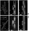
- Figure 3b shows a high-resolution scanning electron microscopy (HR-SEM) image of a fabricated nanoantenna, recorded at beam current of 0.5 nA and low accelerating voltage of 5 kV, for sub-nanometer imaging resolution.
- HR-SEM high-resolution scanning electron microscopy
- Figure 3c shows high-resolution nano-optical mapping of a nanoantenna, recorded at s set lift height of 30 nm using high aspect ratio uncoated Si AFM tip with diameter of 2 nm.
- the numerical results are obtained using High Frequency Structure Simulator (ANSYS HFSS V15) based on the finite element method (FEM).
- ANSYS HFSS V15 High Frequency Structure Simulator
- FEM finite element method
- is the near-field amplitude and ⁇ z the phase.
- the Ez field distribution appears very similar to the Nano optical map ( Figure 3c ), exhibiting identical spatial phase distribution.
- Figures 3e and 3f show the Ex and Ey components (respectively) of the optical near fields.
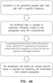
- System 10 further includes a processing unit 26 ( Figure 2 ) for processing the light collected by device 14 and extracting the phase and amplitude information contained therein.
- processing unit 26 is summarized in the flow chart shown in Figure 4 .
- the plasmonic signature derived by processing unit 26 can then be compared to a database of plasmonic signatures correlated with tissue/cell types to identify the tissue/cell present in the probed/scanned volume.
- System 10 of the present invention can be used for qualifying and quantifying biological material in sample or in-vivo and thus can be used in a variety of applications, including, but not limited to, identifying:
- the present invention also encompasses use of a plasmonic beam system for treating biological tissue.
- a system for treating biological material includes a light source for producing a coherent light beam and a device for transforming the coherent light beam into nanoplasmonic waves and projecting the nanoplasmonic waves onto the biological material thereby treating it.
- a typical system setup for performing photo therapy is illustrated in Figure 4b .
- a plasmonic photo-thermal therapy (PTT) system can include a nano-device (Typical dimensions of - 500nmX500nmX200nm) carrying nanoantennas (similar to those described above), that are chemically linked to targeting chemical moiety - a cell specific 'ligand' that is capable of binding to desired cells.
- a nanoantenna array can be covalently linked to an antibody or antibody fragment capable of binding tumorous tissue or a cancer cell, a chemotherapeutic and/or radiosensitising agent such as mitomycin C or an amino acid sequence for targeting to a specific cell compartment (e.g. nucleus).
- the nano device can further include any drug/prodrug for local drug release/activation upon plasmonic excitation or a resonant material (such as Au, Graphene, Al and Si) for increasing the plasmonic response of the nanoantenna array.
- a resonant material such as Au, Graphene, Al and Si
- the nano-device is injected into a tissue, and diffuses to the specific tissue/cell targeted by the ligand.
- a light source e.g. near IR laser, visible laser or a white light source
- plasmonic resonance at the nanoantenna releases/activates the drug at the targeted cells or alternatively, the plasmonic resonance is amplified by the resonant material to generate a localized hot spot which thermally destroys the targeted cells.
- Photodynamic therapy is a similar approach which utilizes light instead of heat for treatment.
- This approach requires the use of a chemical compound - also known as photosensitizer - with a particular type of light to kill cancer cells.
- the photosensitizer in the tumor absorbs the light and generates reactive oxygen species (ROS) - such as hydroxyl radical, singlet oxygen, as well as peroxides - that destroy nearby cancer cells.
- ROS reactive oxygen species
- the present system can be embedded into a medical catheter and used as a tissue sensor in theranostics (diagnostic + therapeutic) applications.
- a catheter can further include a therapeutic unit for treating tissue via, for example, mechanical (cutting), thermal (RF ablation), cryogenic or photoactivation (e.g. PDT) modalities.
- system 10 can also be configured to also provide a therapeutic signal as is described hereinabove.
- Figure 12 illustrates one embodiment of a catheter 100 which includes a system 10 sensor.
- System 10 is fabricated on a silicon chip which is integrated into catheter 100 at a working tip 102.
- Silicon waveguides 104 are used for on-chip signal collection and communication as is described hereinabove.
- Optical signals obtained from the tissue are communicated to an extracorporeal unit 106 via optical fiber 108.
- the optical signal collected by system 10 is processed by extracorporeal unit 106 to identify cells of interest (e.g. malignant cells) in a tissue region scanned. Extracorporeal unit 106 can then guide the therapeutic unit to specifically treat such cells.
- cells of interest e.g. malignant cells
- the nanoantennas of system 10 can be fabricated on a nanometric layer of a chemical substrate (for example on a water-soluble polymer such as vinyl alcohol polymer) which is delivered into the body.
- the formed nanoantennas can be released from the substrate at the site of treatment when exposed to physiological conditions (fluid, pH etc), physical pressure (exposure to ultrasound) and the like.
- physiological conditions fluid, pH etc
- physical pressure exposure to ultrasound
- the nanoantennas of system 10 When the nanoantennas of system 10 are released from the substrate they bind the targeted cell at maximum resolution of ⁇ 10nm, governed by the chemical ligand and device dimensions.
- a 14 weeks old male mouse (C57B) was euthanized by overdose anesthetics.
- a variety of tissues were collected including: striated muscle, cardiac muscle, adipose tissue (retroperitoneal fat), liver, spleen, lung, adrenal, kidney. Each tissue was kept in a separate tube over ice water until analyzed. Tissue characterization for each sample was done at least twice (collected from separate mice).
- a mouse from a melanoma model generated by using the RET proto-oncogene was euthanized and a subcutaneous lesion was excised from the mouse's back, kept in a tube over ice water until analysis. MM cells were identified within the analyzed tissue, well discriminated from the other cells and medium which occupied the bolus.
- a commercially available scanning near field optical microscope was utilized for scanning the samples and to collect the reflected plasmonic waves.
- the plasmonic mode characteristics were extracted using spatial Fourier transform (s-FFT) and the plasmonic waveguide dispersion properties to create a plasmonic image.
- the intensity map of the image represents the amplitude of the plasmonic wave.
- MM cells Cultured human metastatic melanoma (MM) cells from both lines (Mel526. MEL624) yielded identical plasmonic characteristics.
- the human MM cell is represented by a plasmonic wavelength of 130nm (horizontal axis at the graph of Figure 1 ).
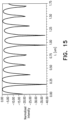
- pellets including a mixture of MM cells and human skin keratinocytes (ratio 1:10) and MM cells and human skin keratocytes were identified based on their plasmonic signature (Keratinocyte signature shown in Figure 15 ).
- plasmonic information obtained for MM cells and keratocytes enables identification of these cell types in any sample by using, for example, spatial scanning approaches.
- Figure 11 presents the results of plasmonic analysis of mouse MM tumor cells based on Human MM cells plasmonic data.
- the bright regions of this intensity map represent mouse MM cells while dark regions represent lack of mouse MM cells.
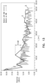
- Figure 14 illustrates the plasmonic peak obtained from a sample containing mouse MM tumor cells mixed with mouse skin cells.
- melanosomes are cell components responsible for the unique plasmonic signature of MM cell.
- Melanosomes in human MM cell culture were tagged with a fluorescent marker (Bruder et al. Melanosomal Dynamics Assessed with a Live-Cell Fluorescent Melanosomal Marker
- NUDE mice 7 weeks old females were supplied by Harlan - Envigo, Israel.
- Human melanoma cells (Mel 526), at dose of 3x10⁶ cells were injected subcutaneously. MM tumors were palpable after 3 weeks, and were excised surgically, as well as samples of normal skin.
- Figures 16-18 illustrate the results obtained using the plasmonic approach of the present invention.
- Figure 17 shows plasmonic imaging of human MM cells grown as a tumor in a NUDE mouse, obtained by post processing the plasmon signatures obtained by the proposed invention. The figure is obtained via similar process to Figure 11 . The bright patterns represent the areas within the tested mouse, for which the signature correlation with isolated MM cells is higher than 80%. This imaging mechanism forms the basis for plasmon - correlation based imaging with sub diffraction optical resolution.
- Figure 18 shows the specific plasmonic thumb printing of a human MM (A line) and a mouse skin (B line) cells on the same chart. The figure is obtained via similar process to Figure 14 . Similar to previous experiments detailed herein ( Figure 14 ), the plasmonic signature of the MM Cell exhibits different signature compared with that of regular skin cells, with less fluctuating character and a significant peak for plasmon wavelength of 300nm.
Landscapes
- Health & Medical Sciences (AREA)
- Life Sciences & Earth Sciences (AREA)
- Engineering & Computer Science (AREA)
- Biomedical Technology (AREA)
- General Health & Medical Sciences (AREA)
- Pathology (AREA)
- Physics & Mathematics (AREA)
- Public Health (AREA)
- Veterinary Medicine (AREA)
- Animal Behavior & Ethology (AREA)
- Chemical & Material Sciences (AREA)
- Nuclear Medicine, Radiotherapy & Molecular Imaging (AREA)
- Radiology & Medical Imaging (AREA)
- Biophysics (AREA)
- General Physics & Mathematics (AREA)
- Heart & Thoracic Surgery (AREA)
- Medical Informatics (AREA)
- Molecular Biology (AREA)
- Surgery (AREA)
- Nanotechnology (AREA)
- Immunology (AREA)
- Biochemistry (AREA)
- Analytical Chemistry (AREA)
- Optics & Photonics (AREA)
- Composite Materials (AREA)
- Condensed Matter Physics & Semiconductors (AREA)
- Materials Engineering (AREA)
- Crystallography & Structural Chemistry (AREA)
- Dermatology (AREA)
- Investigating Or Analysing Materials By Optical Means (AREA)
- Investigating, Analyzing Materials By Fluorescence Or Luminescence (AREA)
- Micro-Organisms Or Cultivation Processes Thereof (AREA)
Claims (14)
- Ein System (10) zur Identifizierung von biologischem Material, umfassend:(a) eine kohärente Lichtquelle (12) zur Bestrahlung des biologischen Materials;(b) eine Vorrichtung (14) zum Sammeln von Lichtwellen, die von dem biologischen Material reflektiert werden, und zum Umwandeln der genannten Lichtwellen in nanoplasmonische Wellen; und(c) ein Verarbeitungsmodul (26) zum Extrahieren von Phasen- und Amplitudeninformationen aus den genannten nanoplasmonischen Wellen, um eine plasmonische Signatur des biologischen Materials bereitzustellen, und zur Identifizierung des biologischen Materials durch Vergleichen der genannten Phasen- und Amplitudeninformationen mit einer Datenbank von plasmonischen Signaturen;wobei das biologische Material aus der Gruppe bestehend aus Geweben, Zellen, subzellulären Strukturen und Plaques ausgewählt wird;und wobei die genannte Vorrichtung mindestens eine Nanoantenne umfasst, die mit mindestens einem plasmonischen Wellenleiter (22) gekoppelt ist.
- Das System nach Anspruch 1, wobei es sich bei den Geweben um normales Gewebe oder Tumorgewebe handelt.
- Das System nach Anspruch 1, wobei die Zellen normale Zellen, abnorme Zellen, bösartige Tumorzellen oder gutartige Tumorzellen sind.
- Das System nach Anspruch 1, wobei das genannte biologische Material mit entzündlichen Prozessen, Fibrose oder Verkalkung in Verbindung steht.
- Das System nach Anspruch 1, wobei die genannte kohärente Lichtquelle so beschaffen ist, dass sie die biologische Probe mit Licht einer Wellenlänge von 450 nm - 10000 nm bestrahlt.
- Das System nach Anspruch 1, wobei der genannte Wellenleiter aus einem nanoplasmonischen Metall-Isolator-Metall-Sandwich hergestellt ist.
- Das System nach Anspruch 6, wobei der genannte Wellenleiter eine Isolierschicht aus Luft, Siliziumoxid, einem Polymer oder einer Keramik enthält.
- Das System nach Anspruch 1, wobei die genannte mindestens eine Antenne ferner einen dritten Nanostab umfasst.
- Das System nach Anspruch 1, das ferner einen nano-metrischen Phasenschieber zur Steuerung der Phase der von dem biologischen Material reflektierten genannten Lichtwellen durch elektrostatische Aufladung enthält.
- Ein Katheter, umfassend ein System nach einem der Ansprüche 1 bis 8, wobei das genannte System in den Katheter eingebettet ist.
- Ein Verfahren zur Identifizierung von biologischem Material, umfassend:(a) Bestrahlung des biologischen Materials mit kohärentem Licht;(b) Auffangen der von dem biologischen Material reflektierten Lichtwellen und Umwandlung der genannten Lichtwellen in nanoplasmonische Wellen; und(c) Extrahieren von Phasen- und Amplitudeninformationen aus den genannten nanoplasmonischen Wellen, wodurch eine plasmonische Signatur des biologischen Materials erhalten wird, und Identifizierung des biologischen Materials durch Vergleichen der genannten Phasen- und Amplitudeninformationen mit einer Datenbank plasmonischer Signaturen;wobei das biologische Material aus der Gruppe bestehend aus Geweben, Zellen, subzellulären Strukturen und Plaques ausgewählt wird;und wobei Schritt (b) durch eine Vorrichtung ausgeführt wird, die mindestens eine Nanoantenne umfasst, die mit mindestens einem plasmonischen Wellenleiter gekoppelt ist.
- Das Verfahren nach Anspruch 10, wobei die Phasen- und Amplitudeninformation durch Durchführung einer räumlichen Fourier-Transformation (s-FFT) an den nanoplasmonischen Wellen innerhalb des genannten mindestens einen Wellenleiters extrahiert wird.
- Das Verfahren nach Anspruch 11, wobei das genannte kohärente Licht eine Wellenlänge von 450 nm - 10000 nm hat.
- Das Verfahren nach Anspruch 11, wobei die genannten Phasen- und Amplitudeninformationen zur Abbildung und Identifizierung des biologischen Materials verwendet werden.
Applications Claiming Priority (2)
| Application Number | Priority Date | Filing Date | Title |
|---|---|---|---|
| US201562244756P | 2015-10-22 | 2015-10-22 | |
| PCT/IL2016/051137 WO2017068586A1 (en) | 2015-10-22 | 2016-10-20 | Systems and methods for identifying and treating biological materials |
Publications (3)
| Publication Number | Publication Date |
|---|---|
| EP3374758A1 EP3374758A1 (de) | 2018-09-19 |
| EP3374758A4 EP3374758A4 (de) | 2019-08-14 |
| EP3374758B1 true EP3374758B1 (de) | 2025-03-05 |
Family
ID=58556881
Family Applications (1)
| Application Number | Title | Priority Date | Filing Date |
|---|---|---|---|
| EP16857048.9A Active EP3374758B1 (de) | 2015-10-22 | 2016-10-20 | Systeme und verfahren zur identifizierung biologischer materialien |
Country Status (4)
| Country | Link |
|---|---|
| US (1) | US11320373B2 (de) |
| EP (1) | EP3374758B1 (de) |
| IL (1) | IL258708B (de) |
| WO (1) | WO2017068586A1 (de) |
Family Cites Families (15)
| Publication number | Priority date | Publication date | Assignee | Title |
|---|---|---|---|---|
| US7569188B2 (en) | 2003-01-03 | 2009-08-04 | Ramot At Tel-Aviv University Ltd | Surface plasmon amplification by stimulated emission of radiation (SPASER) |
| EP2125028A1 (de) * | 2007-01-31 | 2009-12-02 | Agency for Science, Technology And Research | Mit polymer beschichtete nanoteilchen |
| CN101952697B (zh) | 2007-11-02 | 2014-08-13 | 加利福尼亚大学董事会 | 具有超高灵敏度的使用纳米等离子体激元共振器的实时单步生物测定 |
| EP2133688A1 (de) * | 2008-06-11 | 2009-12-16 | Koninklijke Philips Electronics N.V. | Nanoantenne und ihre Verwendungen |
| AR076361A1 (es) * | 2009-04-21 | 2011-06-08 | Immunoligtht Llc | Composicion farmaceutica. kit. metodos y sistemas de conversion ascendente de energia no invasivos para la fotobiomodulacion in-situ |
| US20120184047A1 (en) * | 2009-09-30 | 2012-07-19 | Ge Healthcare Bio-Sciences Ab | Nanoplasmonic device |
| WO2011050272A2 (en) * | 2009-10-23 | 2011-04-28 | Trustees Of Boston University | Nanoantenna arrays for nanospectroscopy, methods of use and methods of high-throughput nanofabrication |
| JP5214036B2 (ja) * | 2010-04-20 | 2013-06-19 | パナソニック株式会社 | 生体に含有される生体成分の濃度を測定する方法 |
| HUE038539T2 (hu) * | 2010-08-27 | 2018-10-29 | Sienna Biopharmaceuticals Inc | Készítmények eljárások célzott hõmodulációhoz |
| US20120281957A1 (en) * | 2011-05-08 | 2012-11-08 | Georgia Tech Research Corporation | Plasmonic and photonic resonator structures and methods for large electromagnetic field enhancements |
| JP2012242387A (ja) * | 2011-05-13 | 2012-12-10 | Imec | 一体型sers測定のための導波路一体型プラズモン共鳴装置 |
| WO2013082304A1 (en) * | 2011-11-29 | 2013-06-06 | The Regents Of The University Of California | Photonic nanoantenna mediated gene circuit reconfiguration |
| WO2013138313A1 (en) * | 2012-03-12 | 2013-09-19 | University Of Houston System | Nanoporous gold nanoparticles as high-payload molecular cargos, photothermal/photodynamic therapeutic agents, and ultrahigh surface-to-volume plasmonic sensors |
| JP6573899B2 (ja) * | 2013-11-17 | 2019-09-11 | クアンタム−エスアイ インコーポレイテッドQuantum−Si Incorporated | 分子をプローブし、検出し、及び分析するための、外部光源を備えた集積デバイス |
| US20160008492A1 (en) * | 2014-07-14 | 2016-01-14 | Emory University | Compositions of saccharide coated nanoparticles and uses |
-
2016
- 2016-10-20 EP EP16857048.9A patent/EP3374758B1/de active Active
- 2016-10-20 WO PCT/IL2016/051137 patent/WO2017068586A1/en not_active Ceased
- 2016-10-20 US US15/769,070 patent/US11320373B2/en active Active
-
2018
- 2018-04-15 IL IL258708A patent/IL258708B/en unknown
Also Published As
| Publication number | Publication date |
|---|---|
| WO2017068586A1 (en) | 2017-04-27 |
| US11320373B2 (en) | 2022-05-03 |
| EP3374758A1 (de) | 2018-09-19 |
| CA3002955A1 (en) | 2017-04-27 |
| US20180321149A1 (en) | 2018-11-08 |
| EP3374758A4 (de) | 2019-08-14 |
| IL258708A (en) | 2018-06-28 |
| IL258708B (en) | 2022-05-01 |
Similar Documents
| Publication | Publication Date | Title |
|---|---|---|
| Li et al. | Design and synthesis of SERS materials for in vivo molecular imaging and biosensing | |
| Antonio et al. | Advances in biomedical Raman microscopy | |
| Son et al. | Potential clinical applications of terahertz radiation | |
| Wen et al. | Real-time intraoperative surface-enhanced Raman spectroscopy-guided thermosurgical eradication of residual microtumors in orthotopic breast cancer | |
| He et al. | SERS/NIR‐II optical nanoprobes for multidimensional tumor imaging from living subjects, pathology, and single cells and guided NIR‐II photothermal therapy | |
| Phan et al. | Photoacoustic imaging-guided photothermal therapy with tumor-targeting HA-FeOOH@ PPy nanorods | |
| Henry et al. | Surface-enhanced Raman spectroscopy biosensing: in vivo diagnostics and multimodal imaging | |
| Wang et al. | Current trends of Raman spectroscopy in clinic settings: opportunities and challenges | |
| US8795628B2 (en) | Molecular imaging of living subjects using Raman spectroscopy and labeled Raman nanoparticles | |
| Doan et al. | Fluorescence/photoacoustic imaging-guided nanomaterials for highly efficient cancer theragnostic agent | |
| Zhou et al. | Gold nanoparticle-decorated silver needle for surface-enhanced Raman spectroscopy screening of residual malachite green in aquaculture products | |
| Friedrich et al. | Optical microscopy systems for the detection of unlabeled nanoparticles | |
| Zhu et al. | Surface-enhanced Raman scattering bioimaging with an ultrahigh signal-to-background ratio under ambient light | |
| Yang et al. | Application of surface-enhanced Raman spectroscopy in head and neck cancer diagnosis | |
| Adarsh et al. | Unveiling NIR Aza‐Boron‐Dipyrromethene (BODIPY) dyes as Raman probes: surface‐enhanced Raman scattering (SERS)‐guided selective detection and imaging of human cancer cells | |
| Dharmalingam et al. | Probing cancer metastasis at a single-cell level with a Raman-functionalized anionic probe | |
| Andreou et al. | Surface-enhanced resonance raman scattering nanoprobe ratiometry for detecting microscopic ovarian cancer via folate receptor targeting | |
| Nasseri et al. | Penetration depth in nanoparticles incorporated radiofrequency hyperthermia into the tissue: comprehensive study with histology and pathology observations | |
| Jin et al. | Integrating Tumor Hypoxic Sensing and Photothermal Therapy Using a Miniaturized Fiber‐Optic Theranostic Probe | |
| Liu et al. | Tunable nanomaterials of intracellular crystallization for in situ biolabeling and biomedical imaging | |
| Darienzo et al. | Surface-enhanced Raman spectroscopy characterization of breast cell phenotypes: effect of nanoparticle geometry | |
| Lee et al. | Janus gold nanodiscs with an asymmetrically positioned polyaniline nano-urchin for photothermal therapy and multimodal imaging in the second near-infrared window | |
| Li et al. | Magnetic field-modulated plasmonic scattering of hybrid nanorods for FFT-weighted OCT imaging in NIR-II | |
| Canpolat et al. | Intra-operative brain tumor detection using elastic light single-scattering spectroscopy: a feasibility study | |
| Tran et al. | Direct synthesis of rev peptide-conjugated gold nanoparticles and their application in cancer therapeutics |
Legal Events
| Date | Code | Title | Description |
|---|---|---|---|
| STAA | Information on the status of an ep patent application or granted ep patent |
Free format text: STATUS: THE INTERNATIONAL PUBLICATION HAS BEEN MADE |
|
| PUAI | Public reference made under article 153(3) epc to a published international application that has entered the european phase |
Free format text: ORIGINAL CODE: 0009012 |
|
| STAA | Information on the status of an ep patent application or granted ep patent |
Free format text: STATUS: REQUEST FOR EXAMINATION WAS MADE |
|
| 17P | Request for examination filed |
Effective date: 20180329 |
|
| AK | Designated contracting states |
Kind code of ref document: A1 Designated state(s): AL AT BE BG CH CY CZ DE DK EE ES FI FR GB GR HR HU IE IS IT LI LT LU LV MC MK MT NL NO PL PT RO RS SE SI SK SM TR |
|
| AX | Request for extension of the european patent |
Extension state: BA ME |
|
| DAV | Request for validation of the european patent (deleted) | ||
| DAX | Request for extension of the european patent (deleted) | ||
| A4 | Supplementary search report drawn up and despatched |
Effective date: 20190712 |
|
| RIC1 | Information provided on ipc code assigned before grant |
Ipc: G01N 21/552 20140101ALN20190708BHEP Ipc: A61B 5/00 20060101AFI20190708BHEP Ipc: A61N 5/06 20060101ALI20190708BHEP Ipc: G01N 21/49 20060101ALN20190708BHEP Ipc: B82Y 30/00 20110101ALN20190708BHEP |
|
| STAA | Information on the status of an ep patent application or granted ep patent |
Free format text: STATUS: EXAMINATION IS IN PROGRESS |
|
| RIC1 | Information provided on ipc code assigned before grant |
Ipc: G01N 21/49 20060101ALN20220304BHEP Ipc: B82Y 30/00 20110101ALN20220304BHEP Ipc: G01N 21/552 20140101ALN20220304BHEP Ipc: A61N 5/06 20060101ALI20220304BHEP Ipc: A61B 5/00 20060101AFI20220304BHEP |
|
| 17Q | First examination report despatched |
Effective date: 20220329 |
|
| REG | Reference to a national code |
Ref country code: DE Ref legal event code: R079 Free format text: PREVIOUS MAIN CLASS: G01N0021660000 Ipc: A61B0005000000 Ref country code: DE Ref legal event code: R079 Ref document number: 602016091470 Country of ref document: DE Free format text: PREVIOUS MAIN CLASS: G01N0021660000 Ipc: A61B0005000000 |
|
| GRAP | Despatch of communication of intention to grant a patent |
Free format text: ORIGINAL CODE: EPIDOSNIGR1 |
|
| STAA | Information on the status of an ep patent application or granted ep patent |
Free format text: STATUS: GRANT OF PATENT IS INTENDED |
|
| RIC1 | Information provided on ipc code assigned before grant |
Ipc: G01N 21/49 20060101ALN20240925BHEP Ipc: B82Y 30/00 20110101ALN20240925BHEP Ipc: G01N 21/552 20140101ALN20240925BHEP Ipc: A61N 5/06 20060101ALI20240925BHEP Ipc: A61B 5/00 20060101AFI20240925BHEP |
|
| INTG | Intention to grant announced |
Effective date: 20241008 |
|
| GRAS | Grant fee paid |
Free format text: ORIGINAL CODE: EPIDOSNIGR3 |
|
| GRAA | (expected) grant |
Free format text: ORIGINAL CODE: 0009210 |
|
| STAA | Information on the status of an ep patent application or granted ep patent |
Free format text: STATUS: THE PATENT HAS BEEN GRANTED |
|
| AK | Designated contracting states |
Kind code of ref document: B1 Designated state(s): AL AT BE BG CH CY CZ DE DK EE ES FI FR GB GR HR HU IE IS IT LI LT LU LV MC MK MT NL NO PL PT RO RS SE SI SK SM TR |
|
| REG | Reference to a national code |
Ref country code: GB Ref legal event code: FG4D |
|
| REG | Reference to a national code |
Ref country code: CH Ref legal event code: EP |
|
| REG | Reference to a national code |
Ref country code: IE Ref legal event code: FG4D |
|
| REG | Reference to a national code |
Ref country code: DE Ref legal event code: R096 Ref document number: 602016091470 Country of ref document: DE |
|
| PG25 | Lapsed in a contracting state [announced via postgrant information from national office to epo] |
Ref country code: RS Free format text: LAPSE BECAUSE OF FAILURE TO SUBMIT A TRANSLATION OF THE DESCRIPTION OR TO PAY THE FEE WITHIN THE PRESCRIBED TIME-LIMIT Effective date: 20250605 |
|
| PG25 | Lapsed in a contracting state [announced via postgrant information from national office to epo] |
Ref country code: FI Free format text: LAPSE BECAUSE OF FAILURE TO SUBMIT A TRANSLATION OF THE DESCRIPTION OR TO PAY THE FEE WITHIN THE PRESCRIBED TIME-LIMIT Effective date: 20250305 |
|
| REG | Reference to a national code |
Ref country code: NL Ref legal event code: MP Effective date: 20250305 |
|
| PG25 | Lapsed in a contracting state [announced via postgrant information from national office to epo] |
Ref country code: ES Free format text: LAPSE BECAUSE OF FAILURE TO SUBMIT A TRANSLATION OF THE DESCRIPTION OR TO PAY THE FEE WITHIN THE PRESCRIBED TIME-LIMIT Effective date: 20250305 |
|
| REG | Reference to a national code |
Ref country code: LT Ref legal event code: MG9D |
|
| PG25 | Lapsed in a contracting state [announced via postgrant information from national office to epo] |
Ref country code: NO Free format text: LAPSE BECAUSE OF FAILURE TO SUBMIT A TRANSLATION OF THE DESCRIPTION OR TO PAY THE FEE WITHIN THE PRESCRIBED TIME-LIMIT Effective date: 20250605 |
|
| PG25 | Lapsed in a contracting state [announced via postgrant information from national office to epo] |
Ref country code: HR Free format text: LAPSE BECAUSE OF FAILURE TO SUBMIT A TRANSLATION OF THE DESCRIPTION OR TO PAY THE FEE WITHIN THE PRESCRIBED TIME-LIMIT Effective date: 20250305 |
|
| PG25 | Lapsed in a contracting state [announced via postgrant information from national office to epo] |
Ref country code: LV Free format text: LAPSE BECAUSE OF FAILURE TO SUBMIT A TRANSLATION OF THE DESCRIPTION OR TO PAY THE FEE WITHIN THE PRESCRIBED TIME-LIMIT Effective date: 20250305 |
|
| PG25 | Lapsed in a contracting state [announced via postgrant information from national office to epo] |
Ref country code: GR Free format text: LAPSE BECAUSE OF FAILURE TO SUBMIT A TRANSLATION OF THE DESCRIPTION OR TO PAY THE FEE WITHIN THE PRESCRIBED TIME-LIMIT Effective date: 20250606 Ref country code: BG Free format text: LAPSE BECAUSE OF FAILURE TO SUBMIT A TRANSLATION OF THE DESCRIPTION OR TO PAY THE FEE WITHIN THE PRESCRIBED TIME-LIMIT Effective date: 20250305 |
|
| REG | Reference to a national code |
Ref country code: AT Ref legal event code: MK05 Ref document number: 1772119 Country of ref document: AT Kind code of ref document: T Effective date: 20250305 |
|
| PG25 | Lapsed in a contracting state [announced via postgrant information from national office to epo] |
Ref country code: NL Free format text: LAPSE BECAUSE OF FAILURE TO SUBMIT A TRANSLATION OF THE DESCRIPTION OR TO PAY THE FEE WITHIN THE PRESCRIBED TIME-LIMIT Effective date: 20250305 |
|
| PG25 | Lapsed in a contracting state [announced via postgrant information from national office to epo] |
Ref country code: SE Free format text: LAPSE BECAUSE OF FAILURE TO SUBMIT A TRANSLATION OF THE DESCRIPTION OR TO PAY THE FEE WITHIN THE PRESCRIBED TIME-LIMIT Effective date: 20250305 |
|
| PG25 | Lapsed in a contracting state [announced via postgrant information from national office to epo] |
Ref country code: SM Free format text: LAPSE BECAUSE OF FAILURE TO SUBMIT A TRANSLATION OF THE DESCRIPTION OR TO PAY THE FEE WITHIN THE PRESCRIBED TIME-LIMIT Effective date: 20250305 |
|
| PG25 | Lapsed in a contracting state [announced via postgrant information from national office to epo] |
Ref country code: PT Free format text: LAPSE BECAUSE OF FAILURE TO SUBMIT A TRANSLATION OF THE DESCRIPTION OR TO PAY THE FEE WITHIN THE PRESCRIBED TIME-LIMIT Effective date: 20250707 |
|
| PG25 | Lapsed in a contracting state [announced via postgrant information from national office to epo] |
Ref country code: IT Free format text: LAPSE BECAUSE OF FAILURE TO SUBMIT A TRANSLATION OF THE DESCRIPTION OR TO PAY THE FEE WITHIN THE PRESCRIBED TIME-LIMIT Effective date: 20250305 Ref country code: PL Free format text: LAPSE BECAUSE OF FAILURE TO SUBMIT A TRANSLATION OF THE DESCRIPTION OR TO PAY THE FEE WITHIN THE PRESCRIBED TIME-LIMIT Effective date: 20250305 |
|
| PG25 | Lapsed in a contracting state [announced via postgrant information from national office to epo] |
Ref country code: AT Free format text: LAPSE BECAUSE OF FAILURE TO SUBMIT A TRANSLATION OF THE DESCRIPTION OR TO PAY THE FEE WITHIN THE PRESCRIBED TIME-LIMIT Effective date: 20250305 |
|
| PG25 | Lapsed in a contracting state [announced via postgrant information from national office to epo] |
Ref country code: EE Free format text: LAPSE BECAUSE OF FAILURE TO SUBMIT A TRANSLATION OF THE DESCRIPTION OR TO PAY THE FEE WITHIN THE PRESCRIBED TIME-LIMIT Effective date: 20250305 Ref country code: CZ Free format text: LAPSE BECAUSE OF FAILURE TO SUBMIT A TRANSLATION OF THE DESCRIPTION OR TO PAY THE FEE WITHIN THE PRESCRIBED TIME-LIMIT Effective date: 20250305 |
|
| PG25 | Lapsed in a contracting state [announced via postgrant information from national office to epo] |
Ref country code: RO Free format text: LAPSE BECAUSE OF FAILURE TO SUBMIT A TRANSLATION OF THE DESCRIPTION OR TO PAY THE FEE WITHIN THE PRESCRIBED TIME-LIMIT Effective date: 20250305 |
|
| PG25 | Lapsed in a contracting state [announced via postgrant information from national office to epo] |
Ref country code: SK Free format text: LAPSE BECAUSE OF FAILURE TO SUBMIT A TRANSLATION OF THE DESCRIPTION OR TO PAY THE FEE WITHIN THE PRESCRIBED TIME-LIMIT Effective date: 20250305 |
|
| PG25 | Lapsed in a contracting state [announced via postgrant information from national office to epo] |
Ref country code: IS Free format text: LAPSE BECAUSE OF FAILURE TO SUBMIT A TRANSLATION OF THE DESCRIPTION OR TO PAY THE FEE WITHIN THE PRESCRIBED TIME-LIMIT Effective date: 20250705 |
|
| REG | Reference to a national code |
Ref country code: CH Ref legal event code: U11 Free format text: ST27 STATUS EVENT CODE: U-0-0-U10-U11 (AS PROVIDED BY THE NATIONAL OFFICE) Effective date: 20251113 |
|
| REG | Reference to a national code |
Ref country code: DE Ref legal event code: R097 Ref document number: 602016091470 Country of ref document: DE |
|
| PGFP | Annual fee paid to national office [announced via postgrant information from national office to epo] |
Ref country code: DE Payment date: 20251030 Year of fee payment: 10 |
|
| PGFP | Annual fee paid to national office [announced via postgrant information from national office to epo] |
Ref country code: GB Payment date: 20251030 Year of fee payment: 10 |
|
| PLBE | No opposition filed within time limit |
Free format text: ORIGINAL CODE: 0009261 |
|
| STAA | Information on the status of an ep patent application or granted ep patent |
Free format text: STATUS: NO OPPOSITION FILED WITHIN TIME LIMIT |
|
| PG25 | Lapsed in a contracting state [announced via postgrant information from national office to epo] |
Ref country code: DK Free format text: LAPSE BECAUSE OF FAILURE TO SUBMIT A TRANSLATION OF THE DESCRIPTION OR TO PAY THE FEE WITHIN THE PRESCRIBED TIME-LIMIT Effective date: 20250305 |
|
| REG | Reference to a national code |
Ref country code: CH Ref legal event code: L10 Free format text: ST27 STATUS EVENT CODE: U-0-0-L10-L00 (AS PROVIDED BY THE NATIONAL OFFICE) Effective date: 20260114 |
|
| PGFP | Annual fee paid to national office [announced via postgrant information from national office to epo] |
Ref country code: FR Payment date: 20251031 Year of fee payment: 10 |
|
| PGFP | Annual fee paid to national office [announced via postgrant information from national office to epo] |
Ref country code: CH Payment date: 20251113 Year of fee payment: 10 |
|
| 26N | No opposition filed |
Effective date: 20251208 |