EP3374600B1 - Resistivity imaging using combination capacitive and inductive sensors - Google Patents
Resistivity imaging using combination capacitive and inductive sensors Download PDFInfo
- Publication number
- EP3374600B1 EP3374600B1 EP16865136.2A EP16865136A EP3374600B1 EP 3374600 B1 EP3374600 B1 EP 3374600B1 EP 16865136 A EP16865136 A EP 16865136A EP 3374600 B1 EP3374600 B1 EP 3374600B1
- Authority
- EP
- European Patent Office
- Prior art keywords
- formation
- antenna
- capacitive
- electrode
- magnetic field
- Prior art date
- Legal status (The legal status is an assumption and is not a legal conclusion. Google has not performed a legal analysis and makes no representation as to the accuracy of the status listed.)
- Active
Links
- 230000001939 inductive effect Effects 0.000 title claims description 42
- 238000003384 imaging method Methods 0.000 title description 5
- 238000005259 measurement Methods 0.000 claims description 67
- 230000015572 biosynthetic process Effects 0.000 claims description 55
- 239000000470 constituent Substances 0.000 claims description 29
- 238000005553 drilling Methods 0.000 claims description 18
- 238000000034 method Methods 0.000 claims description 13
- 230000006698 induction Effects 0.000 claims description 5
- 230000004044 response Effects 0.000 claims description 5
- 238000005755 formation reaction Methods 0.000 description 39
- 239000012530 fluid Substances 0.000 description 12
- 238000012360 testing method Methods 0.000 description 7
- 230000006870 function Effects 0.000 description 5
- 230000008901 benefit Effects 0.000 description 4
- 230000000694 effects Effects 0.000 description 4
- 238000012545 processing Methods 0.000 description 4
- 239000004215 Carbon black (E152) Substances 0.000 description 3
- 230000005540 biological transmission Effects 0.000 description 3
- 238000011156 evaluation Methods 0.000 description 3
- 229930195733 hydrocarbon Natural products 0.000 description 3
- 150000002430 hydrocarbons Chemical class 0.000 description 3
- 238000004519 manufacturing process Methods 0.000 description 3
- 238000004804 winding Methods 0.000 description 3
- 238000004458 analytical method Methods 0.000 description 2
- 230000000712 assembly Effects 0.000 description 2
- 238000000429 assembly Methods 0.000 description 2
- 230000008859 change Effects 0.000 description 2
- 230000008878 coupling Effects 0.000 description 2
- 238000010168 coupling process Methods 0.000 description 2
- 238000005859 coupling reaction Methods 0.000 description 2
- 230000003287 optical effect Effects 0.000 description 2
- 230000008569 process Effects 0.000 description 2
- 238000004088 simulation Methods 0.000 description 2
- 238000013459 approach Methods 0.000 description 1
- 239000003990 capacitor Substances 0.000 description 1
- 239000000969 carrier Substances 0.000 description 1
- 239000000919 ceramic Substances 0.000 description 1
- 238000004891 communication Methods 0.000 description 1
- 238000010276 construction Methods 0.000 description 1
- 238000007405 data analysis Methods 0.000 description 1
- 238000013480 data collection Methods 0.000 description 1
- 230000001934 delay Effects 0.000 description 1
- 230000009977 dual effect Effects 0.000 description 1
- 239000012777 electrically insulating material Substances 0.000 description 1
- 239000000839 emulsion Substances 0.000 description 1
- 239000000835 fiber Substances 0.000 description 1
- 238000002347 injection Methods 0.000 description 1
- 239000007924 injection Substances 0.000 description 1
- 230000001788 irregular Effects 0.000 description 1
- 239000000463 material Substances 0.000 description 1
- 230000007246 mechanism Effects 0.000 description 1
- 230000035515 penetration Effects 0.000 description 1
- 239000002861 polymer material Substances 0.000 description 1
- 239000003381 stabilizer Substances 0.000 description 1
- 230000000638 stimulation Effects 0.000 description 1
- 239000007762 w/o emulsion Substances 0.000 description 1
Images


Classifications
-
- G—PHYSICS
- G01—MEASURING; TESTING
- G01V—GEOPHYSICS; GRAVITATIONAL MEASUREMENTS; DETECTING MASSES OR OBJECTS; TAGS
- G01V3/00—Electric or magnetic prospecting or detecting; Measuring magnetic field characteristics of the earth, e.g. declination, deviation
- G01V3/18—Electric or magnetic prospecting or detecting; Measuring magnetic field characteristics of the earth, e.g. declination, deviation specially adapted for well-logging
- G01V3/26—Electric or magnetic prospecting or detecting; Measuring magnetic field characteristics of the earth, e.g. declination, deviation specially adapted for well-logging operating with magnetic or electric fields produced or modified either by the surrounding earth formation or by the detecting device
- G01V3/28—Electric or magnetic prospecting or detecting; Measuring magnetic field characteristics of the earth, e.g. declination, deviation specially adapted for well-logging operating with magnetic or electric fields produced or modified either by the surrounding earth formation or by the detecting device using induction coils
-
- G—PHYSICS
- G01—MEASURING; TESTING
- G01R—MEASURING ELECTRIC VARIABLES; MEASURING MAGNETIC VARIABLES
- G01R15/00—Details of measuring arrangements of the types provided for in groups G01R17/00 - G01R29/00, G01R33/00 - G01R33/26 or G01R35/00
- G01R15/14—Adaptations providing voltage or current isolation, e.g. for high-voltage or high-current networks
- G01R15/16—Adaptations providing voltage or current isolation, e.g. for high-voltage or high-current networks using capacitive devices
- G01R15/165—Adaptations providing voltage or current isolation, e.g. for high-voltage or high-current networks using capacitive devices measuring electrostatic potential, e.g. with electrostatic voltmeters or electrometers, when the design of the sensor is essential
-
- G—PHYSICS
- G01—MEASURING; TESTING
- G01V—GEOPHYSICS; GRAVITATIONAL MEASUREMENTS; DETECTING MASSES OR OBJECTS; TAGS
- G01V3/00—Electric or magnetic prospecting or detecting; Measuring magnetic field characteristics of the earth, e.g. declination, deviation
- G01V3/18—Electric or magnetic prospecting or detecting; Measuring magnetic field characteristics of the earth, e.g. declination, deviation specially adapted for well-logging
- G01V3/20—Electric or magnetic prospecting or detecting; Measuring magnetic field characteristics of the earth, e.g. declination, deviation specially adapted for well-logging operating with propagation of electric current
-
- G—PHYSICS
- G01—MEASURING; TESTING
- G01V—GEOPHYSICS; GRAVITATIONAL MEASUREMENTS; DETECTING MASSES OR OBJECTS; TAGS
- G01V3/00—Electric or magnetic prospecting or detecting; Measuring magnetic field characteristics of the earth, e.g. declination, deviation
- G01V3/18—Electric or magnetic prospecting or detecting; Measuring magnetic field characteristics of the earth, e.g. declination, deviation specially adapted for well-logging
- G01V3/30—Electric or magnetic prospecting or detecting; Measuring magnetic field characteristics of the earth, e.g. declination, deviation specially adapted for well-logging operating with electromagnetic waves
Definitions
- Geologic formations below the surface of the earth may contain reservoirs of oil and gas, which are retrieved by drilling one or more boreholes into the subsurface of the earth.
- the boreholes are also used to measure various properties of the boreholes and the surrounding subsurface formations.
- Resistivity imaging tools are used in the energy industry to estimate properties of subterranean formations and evaluate formations to determine potential hydrocarbon production. Resistivity tools, such as oil-based mud (OBM) imaging tools are useful in formation evaluation for, e.g., differentiating between hydrocarbon and non-hydrocarbon fluids and measuring formation features such as lithology and fracture characteristics.
- OBM oil-based mud
- US 3 181 057 discloses an induction guard well logging system.
- US 2012/212229 discloses an azimuthally sensitive resistivity logging tool.
- US 3 124 742 discloses an apparatus for investigating earth formations.
- the present invention provides a system for measuring electric characteristics of an earth formation as claimed in claim 1.
- the present invention provides a method of measuring electric characteristics of an earth formation as claimed in claim 8.
- An embodiment of a resistivity measurement apparatus or system includes a downhole tool (e.g., a wireline or LWD tool) that provides resistivity measurements utilizing both inductive and capacitive measurements.
- the inductive measurements are performed by one or more sensors, each of which combines both inductive and capacitive sensing that can be performed at the same location in a borehole.
- the sensor includes an inductive measurement assembly having an antenna (e.g., a single loop sensor), and a capacitive measurement assembly having at least one capacitive electrode that is co-located relative to the antenna.
- An embodiment of an electromagnetic sensor includes an inductive sensor including an antenna and a capacitive galvanic sensor having a co-located electrode that is located in the path of a magnetic field generated by the inductive sensor and is divided into multiple constituent parts.
- the constituent parts also referred to as constituent electrodes
- the constituent parts are not physically connected within the path of the magnetic field (at least to prevent induction of eddy currents around the constituent electrodes), in order to reduce currents in the capacitive electrode and reduce or minimize effects of the capacitive electrode on the magnetic field and associated inductive resistivity measurements.
- an exemplary embodiment of a well drilling, logging and/or production system 10 includes a borehole string 12 that is shown disposed in a wellbore or borehole 14 that penetrates at least one earth formation 16 during a drilling or other downhole operation.
- borehole or “wellbore” refers to a single hole that makes up all or part of a drilled well. It is noted that although the embodiments described herein are described in conjunction with vertical wells, they are not so limited, as they could be used with deviated, horizontal and any other boreholes having any selected path through a formation. As described herein, “formations" refer to the various features and materials that may be encountered in a subsurface environment and surround the borehole.
- a surface structure or surface equipment 18 includes various components such as a wellhead, derrick and/or rotary table for supporting the borehole string, rotating the borehole string and lowering string sections or other downhole components.
- the borehole string 12 is a drillstring including one or more drill pipe sections that extend downward into the borehole 14, and is connected to a drilling assembly 20 that includes a drill bit.
- the surface equipment 18 also includes pumps, fluid sources and other components to circulate drilling fluid through the drilling assembly 20 and the borehole 14.
- the drillstring and the drill bit is shown in FIG. 1 as being rotated by a surface rotary device, the drill bit may be rotated by a downhole motor such as a mud motor.
- the system 10 includes any number of downhole tools 24 for various processes including formation drilling, geosteering, and formation evaluation (FE) for measuring versus depth and/or time one or more physical quantities in or around a borehole.
- the tool 24 may be included in or embodied as a bottomhole assembly (BHA) 22, drillstring component or other suitable carrier.
- BHA bottomhole assembly
- a "carrier” as described herein means any device, device component, combination of devices, media and/or member that may be used to convey, house, support or otherwise facilitate the use of another device, device component, and combination of devices, media and/or member.
- Exemplary non-limiting carriers include drill strings of the coiled tubing type, of the jointed pipe type and any combination or portion thereof.
- Other carrier examples include casing pipes, wirelines, wireline sondes, slickline sondes, drop shots, downhole subs, bottom-hole assemblies, and drill strings.
- the tool 24, the BHA 22 or other portions of the borehole string 12 includes sensor devices configured to measure various parameters of the formation and/or borehole.
- the tool 24 is configured as a downhole resistivity measurement tool, such as a logging-while-drilling (LWD) resistivity tool.
- LWD logging-while-drilling
- system 10 is described in this embodiment as including a drilling assembly, it is not so limited.
- the system 10 may be configured as a measurement system that includes the tool 24 incorporated in a wireline system or a coiled tubing system.
- the tool 24, BHA 22 and/or sensor devices include and/or are configured to communicate with a processor to receive, measure and/or estimate directional and other characteristics of the downhole components, borehole and/or the formation.
- the tool 24 is equipped with transmission equipment to communicate with a processor such as a downhole processor 26 or a surface processing unit 28.
- a processor such as a downhole processor 26 or a surface processing unit 28.
- Such transmission equipment may take any desired form, and different transmission media and connections may be used. Examples of connections include wired, fiber optic, acoustic, wireless connections and mud pulse telemetry.
- the processor may be configured to receive data from the tool 24 and/or process the data to generate formation parameter information.
- the surface processing unit 28 is configured as a surface drilling control unit which controls various drilling parameters such as rotary speed, weight-on-bit, drilling fluid flow parameters and others.
- the processor may also be configured to generate commands via appropriate circuitry to the resistivity measurement tool and cause currents and/or magnetic fields to be injected or induced in the formation 16 surrounding the tool.
- the processor may also detect and/or receive data corresponding to current and/or voltage signals measured via the resistivity measurement tool.
- FIG. 2 illustrates an embodiment of the tool 24, which is configured to take resistivity measurements during rotation of a downhole component such as a drilling assembly, drill string and/or BHA.
- a downhole component such as a drilling assembly, drill string and/or BHA.
- the tool 24 may be incorporated in any rotating downhole component, in this embodiment, the tool 24 is a LWD resistivity imaging tool.
- the tool 24 includes or is mounted to a rotating component 30 such as a length of drill pipe or a BHA component.
- the rotating component extends in an axial direction, i.e., along a long axis of the rotating component.
- the axial direction is shown in FIG. 2 as a "z" direction.
- the tool 24 includes one or more resistivity measurement assemblies or modules 32 embedded in or mounted on the rotating component.
- the modules may be disposed directly at the rotating component or disposed at a support structure such as a rotating or non-rotating sleeve 34.
- Each module 32 includes an isolating structure 36 and one or more resistivity sensors 38 that include a capacitive electrode configured to inject an electric current into the formation 16 and/or detect voltage or current to estimate a resistivity of the formation.
- Each sensor 38 also includes a co-located inductive antenna configured to generate an oscillating magnetic field in the formation and measure the magnitude of currents induced in the formation by the magnetic field.
- the capacitive electrode and inductive antenna are co-located, i.e., located at approximately the same axial and azimuthal or lateral location. Additional electrodes 40 may also be included for transmitting electric current or for acting as guard or focusing electrodes.
- FIG. 2 shows a plurality of sensors 38 arrayed as a row in a lateral direction perpendicular to the axial direction (shown as the "x" direction), or arrayed at successive angular or azimuthal locations "0", however any number and configuration of sensors 38 may be used.
- FIG. 3 shows another embodiment of the tool 24 configured as part of a drill string or other rotating component.
- one or more modules 32 are disposed on a stabilizer component 41 of a drill string.
- the tool 24 may not require an array of measurement modules, but can instead have a single measurement module at a given axial location.
- FIG. 4 shows an embodiment of the tool 24 configured as a wireline tool or other non-rotating tool.
- the module 32 including the sensors 38 is disposed at a pad 42 made from an electrically insulating material such as a ceramic or polymer material.
- the sensors 38 are configured as button electrodes/antennas.
- Each pad 42 may be connected to a body 44 of the tool 24 by extendable arms 46 or other mechanisms for extending the module 32 radially and urging the module 32 against the borehole wall and/or mudcake formed on the borehole wall.
- the pad 42 may include additional components such as electrodes 48 and a non-conductive shield 50 located between the sensors 38 and the electrodes 48.
- the tool 24 is configured to perform measurements within a borehole through which a fluid is circulated that is non-conductive or substantially non-conductive.
- the fluid is an oil-based drilling fluid made from an oil emulsion or a water-in-oil emulsion, such as an oil-based mud (OBM).
- OBM oil-based mud
- Other types of fluids that could be circulated include injection fluids and stimulation fluids such as fracturing fluids.
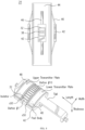
- FIGS. 5 and 6 show an embodiment of the sensor 38 that includes a capacitive electrode assembly 60 and an inductive antenna 62.
- the inductive antenna 62 in this embodiment is a single loop sensor having a selected number or windings.
- the inductive antenna 62 has two windings, although any number (e.g., an integer number) of windings may be formed by the loop.
- the capacitive electrode assembly 60 (or at least a central capacitive electrode 64 described below) is co-located above (radially outwardly) the inductive antenna 62 to allow for measuring resistivity using both inductive and capacitive principles from the same axial and angular location.
- the capacitive electrode assembly 60 performs another important function by acting as a capacitive shield (e.g., by the guard electrode 66; the center electrode 64 may contribute to the shielding function) for the inductive antenna 62 so that capacitive coupling of the antenna 62 and the formation can be avoided.
- the electrode assembly 60 includes a guard or shield electrode 66 that acts like a guard electrode to prevent capacitive coupling between the antenna 62 and the formation.
- the capacitive electrode assembly 60 is configured to ensure that there is no interference between the inductive and capacitive sensors, by having a piecewise construction in which the center capacitive electrode 64 is formed by a plurality of individual constituent electrodes 68 that are unconnected electrically in the region above the antenna 62, i.e., within the path of the magnetic field between the antenna and the formation. This piecewise configuration reduces or eliminates surface eddy currents that could otherwise form in the capacitive electrode and compromise the inductive measurements.
- FIG. 5 shows an example of a configuration of the capacitive electrode 60.
- the electrode includes the center measurement electrode 64 that is formed by the constituent electrodes 68, which are electrically isolated with respect to each other so that there is no direct electrical connection between each other and current cannot directly flow between constituent electrodes 68.
- the constituent electrodes have no direct or physical connection with each other within the main magnetic field of the antenna 62 (e.g., at least a region located radially above the area defined by an antenna loop).
- the constituent electrodes 68 are thus unconnected so as to prevent the induction of eddy currents across the constituent electrodes 68, e.g., around a contour encompassing the plurality of electrodes.
- the contour may be a continuous path (e.g., circular or rectangular) formed by the outer edges of the constituent electrodes 68 or other constituent electrodes in a plane parallel to the surface of the electrode 60 (e.g., in the x-y plane of FIG. 6 ). Examples of a contour 67 are shown in FIGS. 5 and 7 .
- the constituent electrodes are physically unconnected, they may be electrically connected to a measurement circuit.
- an electrical connection e.g., at or near the center point of the electrode 60
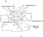
- the center electrode 64 is circular and is divided into four unconnected pie-shaped parts (i.e., the constituent electrodes 68).
- the center electrode 64 is surrounded by the guard electrode 66, which may also be divided into multiple parts, shown in this example as constituent guard electrodes 70. It is noted that the number and configuration of constituent electrodes is not limited to the embodiments described herein, as other shapes and numbers of constituent electrodes may be used as desired.
- FIG. 6 demonstrates how eddy currents that would otherwise be induced are prevented or reduced by the configuration of FIG. 5 .
- FIG. 6 shows simulated surface eddy currents 72 (represented by arrows on the surface of the central and guard electrode) produced by means of the magnetic field generated by the antenna 62. As is evident, no closed loop of eddy currents can occur across the entire central electrode or guard electrode.
- FIGS. 7 and 8 illustrate another embodiment of the center electrode.
- the center electrode 64 is generally rectangular and is divided into four triangle shaped constituent electrodes.
- the constituent electrodes 68 can be further divided or broken up to further reduce the ability of eddy currents to form.
- FIG. 8 shows an example in which the constituent electrodes 68 of FIG. 7 are further divided into slices or other components. These components may be of any shape of form suitable to further reduce the extent of eddy currents in the capacitive electrode.
- each constituent is formed as a series of slices or is formed to follow a meandering path as shown in FIG. 7 .
- the combined inductive and capacitive resistivity sensors described herein may be used in a method of measuring electrical characteristics of a formation.
- An embodiment of a method includes a number of stages discussed further below. The method is described herein in conjunction with the tool 24, although the method may be performed in conjunction with any number and configuration of processors, sensors and tools. In one embodiment, the method includes the execution of all of the following stages in the order described. However, certain stages may be omitted, stages may be added, or the order of the stages changed.
- the tool 24 is lowered in a borehole in an earth formation.
- the tool 24 may be lowered, for example, during a drilling operation, LWD operation or via a wireline.
- a control circuit is used to apply an oscillating voltage or current to the inductive antenna 62 according to a selected frequency.
- the inductive antenna 62 in turn generates an oscillating magnetic field in the earth formation.
- the control circuit or a different measurement circuit detects a response of the antenna 62 to currents induced in the formation.
- the control circuit injects an oscillating measurement current into the formation via the capacitive electrode assembly 60 and detects a resulting signal by the capacitive measurement electrode.
- current can be injected by the capacitive electrode assembly 60 and then the resulting signal can be measured by measuring the (e.g., complex) center electrode 64 voltage, or a voltage can be applied and the resulting signal can be measured by measuring the center electrode 64 current.
- the measurement signal magnitude can be constant and does not need to change.
- the second stages and third stages may be performed sequentially or alternatively (or in any desired manner), or may be performed simultaneously, e.g., by using a different frequency for the inductive antenna 62 and the electrode assembly 60.
- a resistivity of the formation is estimated based on detecting the signal and/or detecting the change in the measurement current.
- Embodiments described herein provide an effective resistivity measurement tool that incorporates both inductive (e.g., single loop) and capacitive (e.g., guarded button) sensors for both wireline and LWD imaging applications.
- inductive e.g., single loop
- capacitive e.g., guarded button
- FIGS. 9-11 illustrate graphs that show results of simulations that demonstrate the effectiveness of the co-located capacitive and inductive sensors described herein. As discussed further below, these tests demonstrate that the capacitive sensor configured according to embodiments described herein can be configured in conjunction with the inductive sensor as described herein without negatively effecting the functionality of the inductive sensor, and can also be used effectively as a capacitive shield.
- FIG. 9 shows the results of the test using a single loop inductive sensor operated without the center or guard electrode of the capacitive/galvanic sensor.
- FIG. 10 shows the results of the test using the single loop sensor operated only with the guard electrode of the capacitive/galvanic electrode assembly.
- FIG. 11 shows the results of the test using the single loop sensor operated with both the center and guard electrode of the capacitive/galvanic electrode assembly.
- FIG. 10 which demonstrates that the segmented guard electrode represents an effective capacitive shield for the loop.
- FIG. 11 demonstrates that the use of the center electrode 60 does not have a significant influence on the functionality of the single loop sensor, thereby showing that the center electrode and/or the assembly 60 can be effectively utilized as a capacitive sensor without negatively affecting the functionality of the loop sensor.
- FIG. 12 demonstrates another significant advantage of the combined inductive and capacitive sensors described herein.
- a potential configuration for performing both inductive and capacitive resistivity measurements using a single tool is a tool on which the inductive sensor and the capacitive sensor are mounted at different locations. In order to determine the precise location for each measurement, the responses could be measured and later superimposed with respect to a desired position that was passed by the sensors at different points of time. This approach would require that every position of a sensor be recalculated as vertical and azimuthal coordinates as well as standoff from a borehole wall.
- the embodiments described herein provide a number of significant advantages due to the ability to configure both types of sensors at the same location.
- One such advantage is that the co-located sensors ensure that the same standoff and other borehole features will be experienced as each sensor performs its respective measurements.
- the embodiments are advantageous in that they reduce the amount of space needed and reduce the complexity of the physical configuration, and can reduce the amount of processing (e.g., calculating time delays and coordinates) required to acquire measurements of a formation.
- the systems described herein may be incorporated in a computer coupled to the tool 24.
- Exemplary components include, without limitation, at least one processor, storage, memory, input devices, output devices and the like. As these components are known to those skilled in the art, these are not depicted in any detail herein.
- the computer may be disposed in at least one of a surface processing unit and a downhole component.
- various analyses and/or analytical components may be used, including digital and/or analog systems.
- the system may have components such as a processor, storage media, memory, input, output, communications link (wired, wireless, pulsed mud, optical or other), user interfaces, software programs, signal processors (digital or analog) and other such components (such as resistors, capacitors, inductors and others) to provide for operation and analyses of the apparatus and methods disclosed herein in any of several manners well-appreciated in the art.
- teachings may be, but need not be, implemented in conjunction with a set of computer executable instructions stored on a computer readable medium, including memory (ROMs, RAMs), optical (CD-ROMs), or magnetic (disks, hard drives), or any other type that when executed causes a computer to implement the method of the present invention.
- ROMs, RAMs random access memory
- CD-ROMs compact disc-read only memory
- magnetic (disks, hard drives) any other type that when executed causes a computer to implement the method of the present invention.
- These instructions may provide for equipment operation, control, data collection and analysis and other functions deemed relevant by a system designer, owner, user or other such personnel, in addition to the functions described in this disclosure.
Landscapes
- Life Sciences & Earth Sciences (AREA)
- Physics & Mathematics (AREA)
- Remote Sensing (AREA)
- Engineering & Computer Science (AREA)
- General Physics & Mathematics (AREA)
- Environmental & Geological Engineering (AREA)
- Geology (AREA)
- General Life Sciences & Earth Sciences (AREA)
- Geophysics (AREA)
- Electromagnetism (AREA)
- Geophysics And Detection Of Objects (AREA)
- Measurement Of Resistance Or Impedance (AREA)
- Investigating Or Analyzing Materials By The Use Of Electric Means (AREA)
Applications Claiming Priority (2)
| Application Number | Priority Date | Filing Date | Title |
|---|---|---|---|
| US201562255118P | 2015-11-13 | 2015-11-13 | |
| PCT/US2016/061637 WO2017083726A1 (en) | 2015-11-13 | 2016-11-11 | Resistivity imaging using combination capacitive and inductive sensors |
Publications (3)
| Publication Number | Publication Date |
|---|---|
| EP3374600A1 EP3374600A1 (en) | 2018-09-19 |
| EP3374600A4 EP3374600A4 (en) | 2019-08-21 |
| EP3374600B1 true EP3374600B1 (en) | 2023-07-12 |
Family
ID=58691005
Family Applications (1)
| Application Number | Title | Priority Date | Filing Date |
|---|---|---|---|
| EP16865136.2A Active EP3374600B1 (en) | 2015-11-13 | 2016-11-11 | Resistivity imaging using combination capacitive and inductive sensors |
Country Status (5)
| Country | Link |
|---|---|
| US (1) | US10042076B2 (pt) |
| EP (1) | EP3374600B1 (pt) |
| BR (1) | BR112018009434B1 (pt) |
| SA (1) | SA518391561B1 (pt) |
| WO (1) | WO2017083726A1 (pt) |
Families Citing this family (5)
| Publication number | Priority date | Publication date | Assignee | Title |
|---|---|---|---|---|
| US10662768B2 (en) * | 2016-11-30 | 2020-05-26 | Exxonmobil Upstream Research Company | Methods of determining a spatial distribution of an injected tracer material within a subterranean formation |
| CN110850480B (zh) * | 2019-11-26 | 2020-06-16 | 自然资源部第一海洋研究所 | 高空间分辨率复合式电极交叉探测方法 |
| GB2590662B (en) * | 2019-12-23 | 2022-10-12 | Flodatix Ltd | Electromagnetic sensor |
| CN111579604B (zh) * | 2020-05-20 | 2023-12-05 | 中国民航大学 | 一种可旋转的平面电容层析成像传感器 |
| US11852006B2 (en) | 2021-06-08 | 2023-12-26 | Halliburton Energy Services, Inc. | Downhole tubular inspection using partial-saturation eddy currents |
Family Cites Families (16)
| Publication number | Priority date | Publication date | Assignee | Title |
|---|---|---|---|---|
| US3124742A (en) * | 1964-03-10 | Apparatus for investigating earth formations having an | ||
| US3181057A (en) | 1960-09-19 | 1965-04-27 | Halliburton Co | Induction-guard well logging system with electrostatic shield guard electrodes |
| GB8607747D0 (en) * | 1986-03-27 | 1986-04-30 | Duracell Int | Device |
| EP0665958B1 (en) * | 1993-07-21 | 1999-01-13 | Western Atlas International, Inc. | Method of determining formation resistivity utilizing combined measurements of inductive and galvanic logging instruments |
| FR2807525B1 (fr) | 2000-04-07 | 2002-06-28 | Schlumberger Services Petrol | Sonde de diagraphie pour l'exploration electrique de formations geologiques traversees par un sondage |
| CA2444942A1 (en) | 2001-04-18 | 2002-10-31 | Baker Hughes Incorporated | An apparatus and method for wellbore resistivity determination and imaging using capacitive coupling |
| US7066282B2 (en) * | 2003-12-23 | 2006-06-27 | Schlumberger Technology Corporation | Apparatus and methods for measuring formation characteristics in presence of conductive and non-conductive muds |
| US7420367B2 (en) | 2004-09-10 | 2008-09-02 | Baker Hughes Incorporated | High-frequency induction imager with concentric coils for MWD and wireline applications |
| US7876102B2 (en) * | 2006-09-14 | 2011-01-25 | Baker Hughes Incorporated | Mixed galvanic-inductive imaging in boreholes |
| US8203344B2 (en) * | 2006-09-14 | 2012-06-19 | Baker Hughes Incorporated | Method and apparatus for resistivity imaging in boreholes with an antenna and two spaced apart electrodes |
| US7902827B2 (en) * | 2006-09-19 | 2011-03-08 | Baker Hughes Incorporated | Method and apparatus for combined induction and imaging well logging |
| US8120361B2 (en) | 2008-11-10 | 2012-02-21 | Cbg Corporation | Azimuthally sensitive resistivity logging tool |
| US20100026305A1 (en) * | 2008-07-31 | 2010-02-04 | Baker Hughes Incorporated | Method and Apparatus for Imaging Boreholes |
| US8258790B2 (en) | 2008-11-20 | 2012-09-04 | Baker Hughes Incorporated | Oscillator sensor for determining a property of an earth formation |
| CN104285033A (zh) | 2011-11-15 | 2015-01-14 | 哈利伯顿能源服务公司 | 增强型电阻率测量的装置、方法和系统 |
| CA2876326A1 (en) * | 2012-06-29 | 2014-01-03 | Halliburton Energy Services, Inc. | Full tensor micro-impedance imaging |
-
2016
- 2016-11-11 EP EP16865136.2A patent/EP3374600B1/en active Active
- 2016-11-11 BR BR112018009434-0A patent/BR112018009434B1/pt active IP Right Grant
- 2016-11-11 WO PCT/US2016/061637 patent/WO2017083726A1/en active Application Filing
- 2016-11-11 US US15/349,224 patent/US10042076B2/en active Active
-
2018
- 2018-05-10 SA SA518391561A patent/SA518391561B1/ar unknown
Also Published As
| Publication number | Publication date |
|---|---|
| US20170139073A1 (en) | 2017-05-18 |
| EP3374600A4 (en) | 2019-08-21 |
| WO2017083726A1 (en) | 2017-05-18 |
| BR112018009434A2 (pt) | 2018-12-04 |
| US10042076B2 (en) | 2018-08-07 |
| EP3374600A1 (en) | 2018-09-19 |
| BR112018009434B1 (pt) | 2023-04-11 |
| SA518391561B1 (ar) | 2022-03-28 |
Similar Documents
| Publication | Publication Date | Title |
|---|---|---|
| EP3374600B1 (en) | Resistivity imaging using combination capacitive and inductive sensors | |
| EP3108272B1 (en) | Electromagnetic transient measurement tool mounted on reduced conductivity tubular | |
| NO20180787A1 (en) | System and method for mapping reservoir properties away from the wellbore | |
| US10031254B2 (en) | Electrode-based tool measurement corrections based on leakage currents estimated using a predetermined internal impedance model or table | |
| CA2928034C (en) | Fiber optic current monitoring for electromagnetic ranging | |
| EP3126627B1 (en) | Downhole tri-axial induction electromagnetic tool | |
| EP3430445B1 (en) | Downhole deep transient measurements with improved sensors | |
| US10605953B2 (en) | Bucking to reduce effects of conducting tubular | |
| WO2013165807A1 (en) | Apparatus and method for deep transient resistivity measurement | |
| WO2017083152A1 (en) | Method for placement of surface electrodes for electromagnetic telemetry | |
| US10520633B2 (en) | Dual-transmitter with short shields for transient MWD resistivity measurements | |
| US10459110B2 (en) | Flexible conductive shield for downhole electromagnetic noise suppression | |
| EP3036400B1 (en) | Methods and devices for extra-deep azimuthal resistivity measurements | |
| AU2016433067B2 (en) | Use of gap subs behind a coil antenna in electromagnetic induction tools | |
| EP3833850A1 (en) | Multiple surface excitation method for determining a location of drilling operations to existing wells |
Legal Events
| Date | Code | Title | Description |
|---|---|---|---|
| STAA | Information on the status of an ep patent application or granted ep patent |
Free format text: STATUS: THE INTERNATIONAL PUBLICATION HAS BEEN MADE |
|
| PUAI | Public reference made under article 153(3) epc to a published international application that has entered the european phase |
Free format text: ORIGINAL CODE: 0009012 |
|
| STAA | Information on the status of an ep patent application or granted ep patent |
Free format text: STATUS: REQUEST FOR EXAMINATION WAS MADE |
|
| 17P | Request for examination filed |
Effective date: 20180611 |
|
| AK | Designated contracting states |
Kind code of ref document: A1 Designated state(s): AL AT BE BG CH CY CZ DE DK EE ES FI FR GB GR HR HU IE IS IT LI LT LU LV MC MK MT NL NO PL PT RO RS SE SI SK SM TR |
|
| AX | Request for extension of the european patent |
Extension state: BA ME |
|
| DAV | Request for validation of the european patent (deleted) | ||
| DAX | Request for extension of the european patent (deleted) | ||
| A4 | Supplementary search report drawn up and despatched |
Effective date: 20190718 |
|
| RIC1 | Information provided on ipc code assigned before grant |
Ipc: G01V 3/20 20060101ALI20190712BHEP Ipc: G01V 3/30 20060101ALI20190712BHEP Ipc: G01V 3/26 20060101ALI20190712BHEP Ipc: E21B 47/00 20120101AFI20190712BHEP Ipc: G01V 3/28 20060101ALI20190712BHEP |
|
| STAA | Information on the status of an ep patent application or granted ep patent |
Free format text: STATUS: EXAMINATION IS IN PROGRESS |
|
| STAA | Information on the status of an ep patent application or granted ep patent |
Free format text: STATUS: EXAMINATION IS IN PROGRESS |
|
| 17Q | First examination report despatched |
Effective date: 20201103 |
|
| STAA | Information on the status of an ep patent application or granted ep patent |
Free format text: STATUS: EXAMINATION IS IN PROGRESS |
|
| GRAP | Despatch of communication of intention to grant a patent |
Free format text: ORIGINAL CODE: EPIDOSNIGR1 |
|
| STAA | Information on the status of an ep patent application or granted ep patent |
Free format text: STATUS: GRANT OF PATENT IS INTENDED |
|
| INTG | Intention to grant announced |
Effective date: 20230126 |
|
| GRAS | Grant fee paid |
Free format text: ORIGINAL CODE: EPIDOSNIGR3 |
|
| GRAA | (expected) grant |
Free format text: ORIGINAL CODE: 0009210 |
|
| STAA | Information on the status of an ep patent application or granted ep patent |
Free format text: STATUS: THE PATENT HAS BEEN GRANTED |
|
| P01 | Opt-out of the competence of the unified patent court (upc) registered |
Effective date: 20230526 |
|
| RAP3 | Party data changed (applicant data changed or rights of an application transferred) |
Owner name: BAKER HUGHES HOLDINGS LLC |
|
| AK | Designated contracting states |
Kind code of ref document: B1 Designated state(s): AL AT BE BG CH CY CZ DE DK EE ES FI FR GB GR HR HU IE IS IT LI LT LU LV MC MK MT NL NO PL PT RO RS SE SI SK SM TR |
|
| REG | Reference to a national code |
Ref country code: CH Ref legal event code: EP |
|
| REG | Reference to a national code |
Ref country code: IE Ref legal event code: FG4D |
|
| REG | Reference to a national code |
Ref country code: DE Ref legal event code: R096 Ref document number: 602016081052 Country of ref document: DE |
|
| REG | Reference to a national code |
Ref country code: NO Ref legal event code: T2 Effective date: 20230712 |
|
| REG | Reference to a national code |
Ref country code: LT Ref legal event code: MG9D |
|
| REG | Reference to a national code |
Ref country code: NL Ref legal event code: MP Effective date: 20230712 |
|
| REG | Reference to a national code |
Ref country code: AT Ref legal event code: MK05 Ref document number: 1587373 Country of ref document: AT Kind code of ref document: T Effective date: 20230712 |
|
| PG25 | Lapsed in a contracting state [announced via postgrant information from national office to epo] |
Ref country code: NL Free format text: LAPSE BECAUSE OF FAILURE TO SUBMIT A TRANSLATION OF THE DESCRIPTION OR TO PAY THE FEE WITHIN THE PRESCRIBED TIME-LIMIT Effective date: 20230712 |
|
| PG25 | Lapsed in a contracting state [announced via postgrant information from national office to epo] |
Ref country code: GR Free format text: LAPSE BECAUSE OF FAILURE TO SUBMIT A TRANSLATION OF THE DESCRIPTION OR TO PAY THE FEE WITHIN THE PRESCRIBED TIME-LIMIT Effective date: 20231013 |
|
| PGFP | Annual fee paid to national office [announced via postgrant information from national office to epo] |
Ref country code: GB Payment date: 20231019 Year of fee payment: 8 |
|
| PG25 | Lapsed in a contracting state [announced via postgrant information from national office to epo] |
Ref country code: ES Free format text: LAPSE BECAUSE OF FAILURE TO SUBMIT A TRANSLATION OF THE DESCRIPTION OR TO PAY THE FEE WITHIN THE PRESCRIBED TIME-LIMIT Effective date: 20230712 |
|
| PG25 | Lapsed in a contracting state [announced via postgrant information from national office to epo] |
Ref country code: IS Free format text: LAPSE BECAUSE OF FAILURE TO SUBMIT A TRANSLATION OF THE DESCRIPTION OR TO PAY THE FEE WITHIN THE PRESCRIBED TIME-LIMIT Effective date: 20231112 |
|
| PG25 | Lapsed in a contracting state [announced via postgrant information from national office to epo] |
Ref country code: SE Free format text: LAPSE BECAUSE OF FAILURE TO SUBMIT A TRANSLATION OF THE DESCRIPTION OR TO PAY THE FEE WITHIN THE PRESCRIBED TIME-LIMIT Effective date: 20230712 Ref country code: RS Free format text: LAPSE BECAUSE OF FAILURE TO SUBMIT A TRANSLATION OF THE DESCRIPTION OR TO PAY THE FEE WITHIN THE PRESCRIBED TIME-LIMIT Effective date: 20230712 Ref country code: PT Free format text: LAPSE BECAUSE OF FAILURE TO SUBMIT A TRANSLATION OF THE DESCRIPTION OR TO PAY THE FEE WITHIN THE PRESCRIBED TIME-LIMIT Effective date: 20231113 Ref country code: LV Free format text: LAPSE BECAUSE OF FAILURE TO SUBMIT A TRANSLATION OF THE DESCRIPTION OR TO PAY THE FEE WITHIN THE PRESCRIBED TIME-LIMIT Effective date: 20230712 Ref country code: LT Free format text: LAPSE BECAUSE OF FAILURE TO SUBMIT A TRANSLATION OF THE DESCRIPTION OR TO PAY THE FEE WITHIN THE PRESCRIBED TIME-LIMIT Effective date: 20230712 Ref country code: IS Free format text: LAPSE BECAUSE OF FAILURE TO SUBMIT A TRANSLATION OF THE DESCRIPTION OR TO PAY THE FEE WITHIN THE PRESCRIBED TIME-LIMIT Effective date: 20231112 Ref country code: HR Free format text: LAPSE BECAUSE OF FAILURE TO SUBMIT A TRANSLATION OF THE DESCRIPTION OR TO PAY THE FEE WITHIN THE PRESCRIBED TIME-LIMIT Effective date: 20230712 Ref country code: GR Free format text: LAPSE BECAUSE OF FAILURE TO SUBMIT A TRANSLATION OF THE DESCRIPTION OR TO PAY THE FEE WITHIN THE PRESCRIBED TIME-LIMIT Effective date: 20231013 Ref country code: FI Free format text: LAPSE BECAUSE OF FAILURE TO SUBMIT A TRANSLATION OF THE DESCRIPTION OR TO PAY THE FEE WITHIN THE PRESCRIBED TIME-LIMIT Effective date: 20230712 Ref country code: ES Free format text: LAPSE BECAUSE OF FAILURE TO SUBMIT A TRANSLATION OF THE DESCRIPTION OR TO PAY THE FEE WITHIN THE PRESCRIBED TIME-LIMIT Effective date: 20230712 Ref country code: AT Free format text: LAPSE BECAUSE OF FAILURE TO SUBMIT A TRANSLATION OF THE DESCRIPTION OR TO PAY THE FEE WITHIN THE PRESCRIBED TIME-LIMIT Effective date: 20230712 |
|
| PGFP | Annual fee paid to national office [announced via postgrant information from national office to epo] |
Ref country code: NO Payment date: 20231023 Year of fee payment: 8 |
|
| PG25 | Lapsed in a contracting state [announced via postgrant information from national office to epo] |
Ref country code: PL Free format text: LAPSE BECAUSE OF FAILURE TO SUBMIT A TRANSLATION OF THE DESCRIPTION OR TO PAY THE FEE WITHIN THE PRESCRIBED TIME-LIMIT Effective date: 20230712 |
|
| PG25 | Lapsed in a contracting state [announced via postgrant information from national office to epo] |
Ref country code: SM Free format text: LAPSE BECAUSE OF FAILURE TO SUBMIT A TRANSLATION OF THE DESCRIPTION OR TO PAY THE FEE WITHIN THE PRESCRIBED TIME-LIMIT Effective date: 20230712 Ref country code: RO Free format text: LAPSE BECAUSE OF FAILURE TO SUBMIT A TRANSLATION OF THE DESCRIPTION OR TO PAY THE FEE WITHIN THE PRESCRIBED TIME-LIMIT Effective date: 20230712 Ref country code: EE Free format text: LAPSE BECAUSE OF FAILURE TO SUBMIT A TRANSLATION OF THE DESCRIPTION OR TO PAY THE FEE WITHIN THE PRESCRIBED TIME-LIMIT Effective date: 20230712 Ref country code: DK Free format text: LAPSE BECAUSE OF FAILURE TO SUBMIT A TRANSLATION OF THE DESCRIPTION OR TO PAY THE FEE WITHIN THE PRESCRIBED TIME-LIMIT Effective date: 20230712 Ref country code: CZ Free format text: LAPSE BECAUSE OF FAILURE TO SUBMIT A TRANSLATION OF THE DESCRIPTION OR TO PAY THE FEE WITHIN THE PRESCRIBED TIME-LIMIT Effective date: 20230712 Ref country code: SK Free format text: LAPSE BECAUSE OF FAILURE TO SUBMIT A TRANSLATION OF THE DESCRIPTION OR TO PAY THE FEE WITHIN THE PRESCRIBED TIME-LIMIT Effective date: 20230712 |
|
| PLBE | No opposition filed within time limit |
Free format text: ORIGINAL CODE: 0009261 |
|
| STAA | Information on the status of an ep patent application or granted ep patent |
Free format text: STATUS: NO OPPOSITION FILED WITHIN TIME LIMIT |