EP3374182B1 - 3d printing of objects with optical functional surfaces - Google Patents
3d printing of objects with optical functional surfaces Download PDFInfo
- Publication number
- EP3374182B1 EP3374182B1 EP16794276.2A EP16794276A EP3374182B1 EP 3374182 B1 EP3374182 B1 EP 3374182B1 EP 16794276 A EP16794276 A EP 16794276A EP 3374182 B1 EP3374182 B1 EP 3374182B1
- Authority
- EP
- European Patent Office
- Prior art keywords
- wall
- printing
- printed
- track
- optical functional
- Prior art date
- Legal status (The legal status is an assumption and is not a legal conclusion. Google has not performed a legal analysis and makes no representation as to the accuracy of the status listed.)
- Active
Links
- 238000007639 printing Methods 0.000 title claims description 28
- 230000003287 optical effect Effects 0.000 title claims description 15
- 238000000034 method Methods 0.000 claims description 21
- 239000000463 material Substances 0.000 claims description 9
- 238000010146 3D printing Methods 0.000 claims description 7
- 238000000151 deposition Methods 0.000 claims description 6
- 238000000576 coating method Methods 0.000 claims description 5
- 239000011248 coating agent Substances 0.000 claims description 4
- 229920001169 thermoplastic Polymers 0.000 claims description 4
- 239000004416 thermosoftening plastic Substances 0.000 claims description 4
- 239000000758 substrate Substances 0.000 description 10
- 238000004519 manufacturing process Methods 0.000 description 4
- 230000008021 deposition Effects 0.000 description 3
- 238000001125 extrusion Methods 0.000 description 3
- 230000008018 melting Effects 0.000 description 2
- 238000002844 melting Methods 0.000 description 2
- 229920000642 polymer Polymers 0.000 description 2
- 239000007787 solid Substances 0.000 description 2
- 229940034610 toothpaste Drugs 0.000 description 2
- 239000000606 toothpaste Substances 0.000 description 2
- 108010014172 Factor V Proteins 0.000 description 1
- 239000000654 additive Substances 0.000 description 1
- 230000000996 additive effect Effects 0.000 description 1
- 239000000919 ceramic Substances 0.000 description 1
- 230000000694 effects Effects 0.000 description 1
- 238000007373 indentation Methods 0.000 description 1
- 238000001746 injection moulding Methods 0.000 description 1
- 239000002184 metal Substances 0.000 description 1
- 229910052751 metal Inorganic materials 0.000 description 1
- 150000002739 metals Chemical class 0.000 description 1
- 238000012986 modification Methods 0.000 description 1
- 230000004048 modification Effects 0.000 description 1
- 239000003973 paint Substances 0.000 description 1
- 230000003362 replicative effect Effects 0.000 description 1
- 239000012815 thermoplastic material Substances 0.000 description 1
- 238000011144 upstream manufacturing Methods 0.000 description 1
Images
Classifications
-
- G—PHYSICS
- G01—MEASURING; TESTING
- G01S—RADIO DIRECTION-FINDING; RADIO NAVIGATION; DETERMINING DISTANCE OR VELOCITY BY USE OF RADIO WAVES; LOCATING OR PRESENCE-DETECTING BY USE OF THE REFLECTION OR RERADIATION OF RADIO WAVES; ANALOGOUS ARRANGEMENTS USING OTHER WAVES
- G01S5/00—Position-fixing by co-ordinating two or more direction or position line determinations; Position-fixing by co-ordinating two or more distance determinations
- G01S5/16—Position-fixing by co-ordinating two or more direction or position line determinations; Position-fixing by co-ordinating two or more distance determinations using electromagnetic waves other than radio waves
-
- B—PERFORMING OPERATIONS; TRANSPORTING
- B05—SPRAYING OR ATOMISING IN GENERAL; APPLYING FLUENT MATERIALS TO SURFACES, IN GENERAL
- B05D—PROCESSES FOR APPLYING FLUENT MATERIALS TO SURFACES, IN GENERAL
- B05D5/00—Processes for applying liquids or other fluent materials to surfaces to obtain special surface effects, finishes or structures
- B05D5/06—Processes for applying liquids or other fluent materials to surfaces to obtain special surface effects, finishes or structures to obtain multicolour or other optical effects
- B05D5/061—Special surface effect
- B05D5/063—Reflective effect
-
- B—PERFORMING OPERATIONS; TRANSPORTING
- B29—WORKING OF PLASTICS; WORKING OF SUBSTANCES IN A PLASTIC STATE IN GENERAL
- B29C—SHAPING OR JOINING OF PLASTICS; SHAPING OF MATERIAL IN A PLASTIC STATE, NOT OTHERWISE PROVIDED FOR; AFTER-TREATMENT OF THE SHAPED PRODUCTS, e.g. REPAIRING
- B29C64/00—Additive manufacturing, i.e. manufacturing of three-dimensional [3D] objects by additive deposition, additive agglomeration or additive layering, e.g. by 3D printing, stereolithography or selective laser sintering
- B29C64/10—Processes of additive manufacturing
- B29C64/106—Processes of additive manufacturing using only liquids or viscous materials, e.g. depositing a continuous bead of viscous material
- B29C64/118—Processes of additive manufacturing using only liquids or viscous materials, e.g. depositing a continuous bead of viscous material using filamentary material being melted, e.g. fused deposition modelling [FDM]
-
- B—PERFORMING OPERATIONS; TRANSPORTING
- B29—WORKING OF PLASTICS; WORKING OF SUBSTANCES IN A PLASTIC STATE IN GENERAL
- B29D—PRODUCING PARTICULAR ARTICLES FROM PLASTICS OR FROM SUBSTANCES IN A PLASTIC STATE
- B29D11/00—Producing optical elements, e.g. lenses or prisms
- B29D11/0073—Optical laminates
-
- B—PERFORMING OPERATIONS; TRANSPORTING
- B29—WORKING OF PLASTICS; WORKING OF SUBSTANCES IN A PLASTIC STATE IN GENERAL
- B29D—PRODUCING PARTICULAR ARTICLES FROM PLASTICS OR FROM SUBSTANCES IN A PLASTIC STATE
- B29D11/00—Producing optical elements, e.g. lenses or prisms
- B29D11/0074—Production of other optical elements not provided for in B29D11/00009- B29D11/0073
-
- B—PERFORMING OPERATIONS; TRANSPORTING
- B33—ADDITIVE MANUFACTURING TECHNOLOGY
- B33Y—ADDITIVE MANUFACTURING, i.e. MANUFACTURING OF THREE-DIMENSIONAL [3-D] OBJECTS BY ADDITIVE DEPOSITION, ADDITIVE AGGLOMERATION OR ADDITIVE LAYERING, e.g. BY 3-D PRINTING, STEREOLITHOGRAPHY OR SELECTIVE LASER SINTERING
- B33Y10/00—Processes of additive manufacturing
-
- B—PERFORMING OPERATIONS; TRANSPORTING
- B33—ADDITIVE MANUFACTURING TECHNOLOGY
- B33Y—ADDITIVE MANUFACTURING, i.e. MANUFACTURING OF THREE-DIMENSIONAL [3-D] OBJECTS BY ADDITIVE DEPOSITION, ADDITIVE AGGLOMERATION OR ADDITIVE LAYERING, e.g. BY 3-D PRINTING, STEREOLITHOGRAPHY OR SELECTIVE LASER SINTERING
- B33Y80/00—Products made by additive manufacturing
-
- F—MECHANICAL ENGINEERING; LIGHTING; HEATING; WEAPONS; BLASTING
- F21—LIGHTING
- F21V—FUNCTIONAL FEATURES OR DETAILS OF LIGHTING DEVICES OR SYSTEMS THEREOF; STRUCTURAL COMBINATIONS OF LIGHTING DEVICES WITH OTHER ARTICLES, NOT OTHERWISE PROVIDED FOR
- F21V1/00—Shades for light sources, i.e. lampshades for table, floor, wall or ceiling lamps
- F21V1/26—Manufacturing shades
-
- F—MECHANICAL ENGINEERING; LIGHTING; HEATING; WEAPONS; BLASTING
- F21—LIGHTING
- F21V—FUNCTIONAL FEATURES OR DETAILS OF LIGHTING DEVICES OR SYSTEMS THEREOF; STRUCTURAL COMBINATIONS OF LIGHTING DEVICES WITH OTHER ARTICLES, NOT OTHERWISE PROVIDED FOR
- F21V7/00—Reflectors for light sources
- F21V7/04—Optical design
- F21V7/048—Optical design with facets structure
-
- B—PERFORMING OPERATIONS; TRANSPORTING
- B29—WORKING OF PLASTICS; WORKING OF SUBSTANCES IN A PLASTIC STATE IN GENERAL
- B29L—INDEXING SCHEME ASSOCIATED WITH SUBCLASS B29C, RELATING TO PARTICULAR ARTICLES
- B29L2011/00—Optical elements, e.g. lenses, prisms
-
- B—PERFORMING OPERATIONS; TRANSPORTING
- B29—WORKING OF PLASTICS; WORKING OF SUBSTANCES IN A PLASTIC STATE IN GENERAL
- B29L—INDEXING SCHEME ASSOCIATED WITH SUBCLASS B29C, RELATING TO PARTICULAR ARTICLES
- B29L2011/00—Optical elements, e.g. lenses, prisms
- B29L2011/0083—Reflectors
-
- B—PERFORMING OPERATIONS; TRANSPORTING
- B29—WORKING OF PLASTICS; WORKING OF SUBSTANCES IN A PLASTIC STATE IN GENERAL
- B29L—INDEXING SCHEME ASSOCIATED WITH SUBCLASS B29C, RELATING TO PARTICULAR ARTICLES
- B29L2031/00—Other particular articles
- B29L2031/747—Lightning equipment
-
- B—PERFORMING OPERATIONS; TRANSPORTING
- B29—WORKING OF PLASTICS; WORKING OF SUBSTANCES IN A PLASTIC STATE IN GENERAL
- B29L—INDEXING SCHEME ASSOCIATED WITH SUBCLASS B29C, RELATING TO PARTICULAR ARTICLES
- B29L2031/00—Other particular articles
- B29L2031/747—Lightning equipment
- B29L2031/7472—Lampshades
Definitions
- the present invention relates to 3D printing of objects with at least one wall having a first surface and a second, opposite surface, wherein said first surface is intended to serve as an optical functional surface.
- the objects are collimators or reflectors, and the optical functional surface is for light collimation or for light reflection.
- Digital fabrication has begun to transform the nature of global manufacturing.
- 3D printing One of the aspects of digital fabrication is 3D printing.
- 3D printing can also be used in producing molds which can then be used for replicating objects.
- polyjet technique For this purpose the use of polyjet technique has been suggested.
- This technique makes use of layer by layer deposition of photopolymerisable material which is cured after each deposition to form a solid structure. While this technique produces smooth surfaces the photo curable materials are not very stable and they also have relatively low thermal conductivity to be useful for injection molding applications.
- FDM printers use a thermoplastic filament, which is heated to its melting point and then extruded, layer by layer, to create a three dimensional object. FDM printers are relatively fast and can be used for printing complicated object.
- FDM is also an ideal printing process especially when printing conical hemispherical or faceted objects which are used in lighting.
- US20140070445A1 describes a method for FDM to produce an object and various ways of varying a deposit rate of the build material during the extrusion onto an exterior wall of the object to create a non-uniform surface texture on the exterior wall. For this purpose they suggest varying the extrusion rate, distance in a direction during extrusion, and varying the velocity in x-y direction.
- XP002756684 from Lennovation's hub discloses a method of additive manufacturing an object having an inner portion and a frustum shape.
- this and other objects are achieved by a method for 3D printing an object in accordance with claim 1.
- the 3D object is thus oriented during printing such that the first surface, intended to be used as an optical functional surface, faces away from the x-y plane, i.e. typically away from the support or platform on which the 3D object is printed upon.
- the first surface becomes smoother than the second, opposite surface of the wall.
- the present invention is based on the insight that when a non solid object including a wall formed by consecutive layers of printing material, the surface properties of this wall will depend on the orientation of the object during printing. If the wall is vertical (e.g. a vertical cylinder), the inside and outside surfaces of the wall will have the same roughness. However, when the wall is inclined with respect to the x-y plane, such as a tilted cylinder or a conical object, any surface facing the platform is rougher than the opposite surface facing away from the platform.
- an optical functional surface e.g. a surface used for collimation of light or esthetics, may be oriented so that it is printed more smoothly than the opposite surface of the wall.
- the wall which is formed by consecutive tracks of printed material will have a width (in the x-y plane) defined by the diameter of the nozzle. Typically, this will thus be a relatively thin wall. Still, the width of the track (and the wall) is preferably greater than the thickness of each layer, in order to achieve the desired smoothness. According to a preferred embodiment, a ratio of the nozzle diameter and the thickness of the printed layer is greater than three, or even greater than five.
- 3D objects may present walls with surfaces that are possible to orient such that one surface of the wall is smoother than the other surface.
- the invention is particularly useful when the wall forms a contour surrounding a hollow interior.
- Specific examples of such shapes are cylinders (tilted with respect to the x-y plane), (truncated) cones, (truncated) pyramids, half-spheres etc.
- the shapes may be rotational symmetrical, but this is not necessary.
- the wall may simply be a small part of a more complex object.
- the only condition in order to make the invention relevant is that the wall is formed by a plurality of tracks printed onto each other.
- the difference in surface smoothness between the first and second surfaces will be a function also on the inclination of the wall or portion of the wall with respect to the x-y plane.
- the wall is perpendicular to the surface or makes a small angle (less than 0-5 degrees) with respect to the normal (z-axis) there is not much difference in the quality of the inner and outer surfaces.
- the angle between the tangent (or tangent surface) of the first surface and the normal (z-axis) is in the range 5-45 degrees, and preferably in the range 5-35 degrees.
- the smoothness obtained by ensuring the correct orientation during printing according to the present invention is sufficient.
- the functional surface will be coated in order to obtain the desired properties.
- the smoother surface obtained by the present invention will be highly advantageous for such coating.
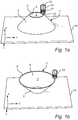
- FIGS 1a and 1b show FDM printing of an object 1, in the illustrated case in the shape of a cone.
- FDM printing is well known in the art, and will not be described in detail here.
- an FDM printer has a printing head 10 including a feeder 11 for feeding a filament 12 of thermoplastic material through a channel in a nozzle 13.
- a heater (not shown) configured to heat the filament to its melting point, such that the thermoplastic is extruded and deposited by the nozzle in melted form.
- the printing head 10 is arranged to be moved in an x-y plane while depositing the melted thermoplastic to print one layer of the object.
- the object 1 As consecutive layers are printed on top of each other, the object is built layer by layer in the z-direction.
- the object is typically printed on some kind of support or substrate 14.
- the object 1 has a wall 2, here a contour wall surrounding a hollow interior 3. The interior may be closed in its top and/or bottom end, but may also be open.
- the wall 2 has a first surface 4, 4' facing away from the substrate, and a second surface 5, 5' facing towards the substrate.
- the object - in the illustrated case the cone - is printed with an orientation such that an optical functional surface of the object faces away from the substrate (i.e. it is the first surface).
- An optical functional surface in this context is a surface intended to interact with light in a desired manner, and may be a surface intended to be reflective or esthetic.
- the first surface will be smoother than the second surface.
- the first surface i.e. the smooth surface to be used as an optical functional surface
- the first surface i.e. the smooth surface to be used as an optical functional surface
- the first surface i.e. the smooth surface to be used as an optical functional surface
- the first surface i.e. the smooth surface to be used as an optical functional surface
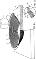
- Figure 2a shows how the nozzle of a printer head 10 is moved around a predefined path 15, here substantially circular, while depositing a track 16 of melted filament on previously deposited layers.
- each layer of the wall may be printed in discrete movements, one at a time, or the wall may be printed with one single spiral movement of the printer head.
- This technique is known as a "spiralize" function, and is available in some 3D-printing software.
- the accumulated effect of the sharp edge 18 is that the surface 5' facing the substrate (i.e. the surface where the sharp edges 18 are located) will be rougher than the opposite surface 4' facing away from the substrate 14, where the consecutive layers 16, 17 form a more regular step-pattern.
- the amount of "sag”, and thus the roughness of the surface, will depend on several factors, including the diameter of the nozzle 13 defining the width of the printed track 16, and the thickness of the printed track 16. In the example illustrated in figure 2a , it is clear that the width w of track 16 is significantly greater than the thickness d of the track 16, approximately a factor five greater. Therefore, the material (the melted filament 12) is pressed (by the nozzle 13) during printing to form the flat track 16, rather like when applying a thin layer of toothpaste on a toothbrush. In portions where there is no support to counter-act this pressure, the track will "sag” as discussed above, just like the toothpaste will be forced beyond the upper surface of the toothbrush if you apply it outside the edges of the brush.
- the smoother surface of the wall 2, i.e. the surface 4, 4' facing away from the substrate, is intended to be used as an optical functional surface.
- the surface may be coated with a suitable coating to create or improve the surface properties.
- coatings may be used to improve smoothness, make the surface reflective or diffusive, or to simply paint the surface.
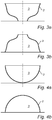
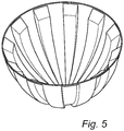
- Figures 3 - 5 show further example of objects which advantageously may be printed using 3D printing according to the present invention. These objects are all formed by a contour wall 2 surrounding a hollow interior space 3.
- the 3D object in figures 3a-3b is rotational symmetrical.
- the inside of the object is smoother than the outside, and the object may be used e.g. as a light collimator in a luminaire.
- the outside is smoother than the inside, and the object may be used e.g. as a lamp shade.
- the 3D object in figures 4a-4b is also rotational symmetrical, but contrary to the objects in figures 1-3 the object in figures 4a-4b is closed in one end, and has the shape of a semi-sphere.
- the inside of the semi-sphere is smoother than the outside, and the semi-sphere may be used e.g. as a collimator or reflector.
- the outside is smoother than the inside.
- Such an object for example can be filled with index matching polymer to be used as lens.
- the object in figure 5 is not rotational symmetrical and it has indentations, but similar to the object in figure 4 it is closed in one end to form a dome shape. With the orientation chosen in figure 5 , the inside of the dome-shaped object will be smoother than the outside, and the object may be used as a reflector/collimator.
- any 3D-printed object having a wall formed by consecutive tracks printed onto each other can be oriented during printing according to the invention to ensure that one surface of the wall is smoother than the other.
- the wall may comprise several facets, or portions, each having a different tangent (or tangent surface). In this case, the angle between the tangent and the normal (z-axis) may be different, resulting in different smoothness for different portions of the wall.
Landscapes
- Engineering & Computer Science (AREA)
- Manufacturing & Machinery (AREA)
- Materials Engineering (AREA)
- Chemical & Material Sciences (AREA)
- Physics & Mathematics (AREA)
- Mechanical Engineering (AREA)
- Optics & Photonics (AREA)
- General Engineering & Computer Science (AREA)
- Health & Medical Sciences (AREA)
- Ophthalmology & Optometry (AREA)
- General Physics & Mathematics (AREA)
- Radar, Positioning & Navigation (AREA)
- Remote Sensing (AREA)
- Electromagnetism (AREA)
Priority Applications (1)
| Application Number | Priority Date | Filing Date | Title |
|---|---|---|---|
| PL16794276T PL3374182T3 (pl) | 2015-11-09 | 2016-11-07 | Drukowanie 3d obiektów z optycznymi powierzchniami funkcjonalnymi |
Applications Claiming Priority (2)
| Application Number | Priority Date | Filing Date | Title |
|---|---|---|---|
| EP15193623 | 2015-11-09 | ||
| PCT/EP2016/076831 WO2017080951A1 (en) | 2015-11-09 | 2016-11-07 | 3d printing of objects with optical functional surfaces |
Publications (2)
| Publication Number | Publication Date |
|---|---|
| EP3374182A1 EP3374182A1 (en) | 2018-09-19 |
| EP3374182B1 true EP3374182B1 (en) | 2020-06-17 |
Family
ID=54601611
Family Applications (1)
| Application Number | Title | Priority Date | Filing Date |
|---|---|---|---|
| EP16794276.2A Active EP3374182B1 (en) | 2015-11-09 | 2016-11-07 | 3d printing of objects with optical functional surfaces |
Country Status (6)
| Country | Link |
|---|---|
| US (1) | US11072110B2 (enExample) |
| EP (1) | EP3374182B1 (enExample) |
| JP (1) | JP6907200B2 (enExample) |
| CN (1) | CN108349234B (enExample) |
| PL (1) | PL3374182T3 (enExample) |
| WO (1) | WO2017080951A1 (enExample) |
Families Citing this family (17)
| Publication number | Priority date | Publication date | Assignee | Title |
|---|---|---|---|---|
| WO2018224395A1 (en) * | 2017-06-09 | 2018-12-13 | Philips Lighting Holding B.V. | Optical component for generating light effect |
| US20200223130A1 (en) * | 2017-07-20 | 2020-07-16 | Signify Holding B.V. | Hiding optical defect lines on parts of fdm printed luminaires with metallic look |
| EP3473418B1 (en) * | 2017-10-19 | 2023-12-06 | Essilor International | Method for manufacturing an ophthalmic lens |
| USD900299S1 (en) * | 2018-06-11 | 2020-10-27 | Fumex Ab | Ventilation hood with arm |
| US11220041B2 (en) * | 2018-08-08 | 2022-01-11 | Anna CHEN-IUN-TAI | 3-D printing at inclined angles |
| CN109967907A (zh) * | 2019-04-17 | 2019-07-05 | 湖北三环锻造有限公司 | 一种智能化模具3d打印增材制造工艺 |
| CN110053250B (zh) * | 2019-05-24 | 2022-10-14 | 泉州市比邻三维科技有限公司 | 一种改进的3d打印方法 |
| US11828438B2 (en) * | 2019-07-09 | 2023-11-28 | Signify Holding B.V. | Printing structures with openings in a side surface |
| CN110434337A (zh) * | 2019-08-23 | 2019-11-12 | 广州番禺职业技术学院 | 一种3d打印制备仿生智能金属材料表面的制备方法 |
| US12151439B2 (en) * | 2019-11-22 | 2024-11-26 | DEMCON bond 3D B.V. | Extrusion-based additive manufacturing: method, 3D printing system, and 3D printed object |
| CN110789116A (zh) * | 2019-12-05 | 2020-02-14 | 盈创新材料(苏州)有限公司 | 3d打印喷头油墨宽度及厚度控制方法 |
| EP3888886A1 (en) * | 2020-03-31 | 2021-10-06 | Signify Holding B.V. | 3d printed object covered with a heat shrink |
| CN111910926A (zh) * | 2020-08-05 | 2020-11-10 | 李享 | 一种建筑3d打印机用打印头及其使用方法 |
| US11982990B2 (en) * | 2021-03-24 | 2024-05-14 | Gantri, Inc. | System and methods for manufacturing a custom lighting product |
| CN113085188B (zh) * | 2021-04-01 | 2022-09-13 | 上海酷鹰机器人科技有限公司 | 一种打印轨迹线的获取方法及装置 |
| EP4388248B1 (en) | 2021-08-16 | 2025-04-02 | Signify Holding B.V. | A lighting device, luminaire, and method manufacturing |
| JP7490700B2 (ja) * | 2022-03-30 | 2024-05-27 | 本田技研工業株式会社 | 三次元造形方法及び三次元造形装置 |
Family Cites Families (15)
| Publication number | Priority date | Publication date | Assignee | Title |
|---|---|---|---|---|
| US7874705B2 (en) * | 2007-10-01 | 2011-01-25 | Marnie Deacon Kenney | Cover for a luminary device |
| US8920697B2 (en) * | 2010-09-17 | 2014-12-30 | Stratasys, Inc. | Method for building three-dimensional objects in extrusion-based additive manufacturing systems using core-shell consumable filaments |
| US8529240B2 (en) * | 2011-07-05 | 2013-09-10 | Makerbot Industries, Llc | Three-dimensional surface texturing |
| US8778252B2 (en) * | 2012-01-20 | 2014-07-15 | Wisconsin Alumni Research Foundation | Three-dimensional printing system using dual rotation axes |
| US9643362B2 (en) | 2013-03-15 | 2017-05-09 | Microsoft Technology Licensing, Llc | Full color three-dimensional object fabrication |
| US9126367B1 (en) * | 2013-03-22 | 2015-09-08 | Markforged, Inc. | Three dimensional printer for fiber reinforced composite filament fabrication |
| WO2014194959A1 (en) * | 2013-06-06 | 2014-12-11 | Universität Duisburg-Essen | Device for collimating electromagnetic radiation |
| US9266287B2 (en) * | 2013-09-18 | 2016-02-23 | Disney Enterprises, Inc. | 3D printing with custom surface reflectance |
| WO2015077536A1 (en) * | 2013-11-22 | 2015-05-28 | Turner Innovations | High-density compounds for 3d printing |
| CN104015358B (zh) * | 2014-06-03 | 2016-10-12 | 中国科学院高能物理研究所 | 一种编码准直器的制作方法 |
| JP6485617B2 (ja) * | 2014-06-20 | 2019-03-20 | 泰 金田 | 支持なしで水平にフィラメントを配列する3次元印刷方法 |
| KR20170086462A (ko) | 2014-08-28 | 2017-07-26 | 시멘 샬레 스코그스루드 | 3d 프린터 |
| TWI630124B (zh) | 2014-11-10 | 2018-07-21 | 三緯國際立體列印科技股份有限公司 | 立體列印裝置 |
| CN204686014U (zh) * | 2015-04-23 | 2015-10-07 | 马承伟 | 3d打印装置 |
| CN104890248A (zh) * | 2015-07-05 | 2015-09-09 | 冯圣冰 | 一种sla-3d打印机 |
-
2016
- 2016-11-07 US US15/773,185 patent/US11072110B2/en active Active
- 2016-11-07 PL PL16794276T patent/PL3374182T3/pl unknown
- 2016-11-07 CN CN201680065247.9A patent/CN108349234B/zh active Active
- 2016-11-07 EP EP16794276.2A patent/EP3374182B1/en active Active
- 2016-11-07 WO PCT/EP2016/076831 patent/WO2017080951A1/en not_active Ceased
- 2016-11-07 JP JP2018523482A patent/JP6907200B2/ja active Active
Non-Patent Citations (1)
| Title |
|---|
| None * |
Also Published As
| Publication number | Publication date |
|---|---|
| EP3374182A1 (en) | 2018-09-19 |
| JP2019502568A (ja) | 2019-01-31 |
| JP6907200B2 (ja) | 2021-07-21 |
| WO2017080951A1 (en) | 2017-05-18 |
| PL3374182T3 (pl) | 2020-11-16 |
| US11072110B2 (en) | 2021-07-27 |
| US20180319076A1 (en) | 2018-11-08 |
| CN108349234B (zh) | 2021-03-12 |
| CN108349234A (zh) | 2018-07-31 |
Similar Documents
| Publication | Publication Date | Title |
|---|---|---|
| EP3374182B1 (en) | 3d printing of objects with optical functional surfaces | |
| JP7592008B2 (ja) | ビルドプレートに対して45°未満の傾斜角度で物体を印刷するための方法 | |
| CN109414875B (zh) | 3d打印反射器及其制造方法 | |
| CN110382205B (zh) | 用于打印光滑fdm 3d物品的芯-壳型丝 | |
| JP7036987B2 (ja) | 物品の平滑な表面をfdm印刷するための印刷方法 | |
| JP2019502568A5 (enExample) | ||
| JP6484766B1 (ja) | カスタマイズ可能な3d印刷照明デバイス | |
| WO2018077712A1 (en) | Method for 3d printing a 3d item with a decorative surface texture | |
| CN110062691B (zh) | 基于挤出的增材制造方法 | |
| WO2020043647A1 (en) | Method of manufacturing an object by means of 3d printing | |
| EP4126506B1 (en) | Method of manufacturing and 3d printed object covered with a heat shrink sleeve | |
| US11828438B2 (en) | Printing structures with openings in a side surface | |
| CN113597530B (zh) | 可调节光源保持件、可定向聚光灯及其制造方法 |
Legal Events
| Date | Code | Title | Description |
|---|---|---|---|
| STAA | Information on the status of an ep patent application or granted ep patent |
Free format text: STATUS: UNKNOWN |
|
| STAA | Information on the status of an ep patent application or granted ep patent |
Free format text: STATUS: THE INTERNATIONAL PUBLICATION HAS BEEN MADE |
|
| PUAI | Public reference made under article 153(3) epc to a published international application that has entered the european phase |
Free format text: ORIGINAL CODE: 0009012 |
|
| STAA | Information on the status of an ep patent application or granted ep patent |
Free format text: STATUS: REQUEST FOR EXAMINATION WAS MADE |
|
| 17P | Request for examination filed |
Effective date: 20180611 |
|
| AK | Designated contracting states |
Kind code of ref document: A1 Designated state(s): AL AT BE BG CH CY CZ DE DK EE ES FI FR GB GR HR HU IE IS IT LI LT LU LV MC MK MT NL NO PL PT RO RS SE SI SK SM TR |
|
| AX | Request for extension of the european patent |
Extension state: BA ME |
|
| RAP1 | Party data changed (applicant data changed or rights of an application transferred) |
Owner name: PHILIPS LIGHTING HOLDING B.V. |
|
| DAV | Request for validation of the european patent (deleted) | ||
| DAX | Request for extension of the european patent (deleted) | ||
| RAP1 | Party data changed (applicant data changed or rights of an application transferred) |
Owner name: SIGNIFY HOLDING B.V. |
|
| STAA | Information on the status of an ep patent application or granted ep patent |
Free format text: STATUS: EXAMINATION IS IN PROGRESS |
|
| 17Q | First examination report despatched |
Effective date: 20190401 |
|
| REG | Reference to a national code |
Ref country code: DE Ref legal event code: R079 Ref document number: 602016038362 Country of ref document: DE Free format text: PREVIOUS MAIN CLASS: B33Y0010000000 Ipc: B29C0064106000 |
|
| GRAP | Despatch of communication of intention to grant a patent |
Free format text: ORIGINAL CODE: EPIDOSNIGR1 |
|
| STAA | Information on the status of an ep patent application or granted ep patent |
Free format text: STATUS: GRANT OF PATENT IS INTENDED |
|
| RIC1 | Information provided on ipc code assigned before grant |
Ipc: G01S 5/16 20060101ALI20191216BHEP Ipc: B33Y 10/00 20150101ALI20191216BHEP Ipc: B33Y 80/00 20150101ALI20191216BHEP Ipc: B29C 64/106 20170101AFI20191216BHEP |
|
| INTG | Intention to grant announced |
Effective date: 20200110 |
|
| GRAS | Grant fee paid |
Free format text: ORIGINAL CODE: EPIDOSNIGR3 |
|
| GRAA | (expected) grant |
Free format text: ORIGINAL CODE: 0009210 |
|
| STAA | Information on the status of an ep patent application or granted ep patent |
Free format text: STATUS: THE PATENT HAS BEEN GRANTED |
|
| AK | Designated contracting states |
Kind code of ref document: B1 Designated state(s): AL AT BE BG CH CY CZ DE DK EE ES FI FR GB GR HR HU IE IS IT LI LT LU LV MC MK MT NL NO PL PT RO RS SE SI SK SM TR |
|
| REG | Reference to a national code |
Ref country code: GB Ref legal event code: FG4D |
|
| REG | Reference to a national code |
Ref country code: CH Ref legal event code: EP |
|
| REG | Reference to a national code |
Ref country code: IE Ref legal event code: FG4D |
|
| REG | Reference to a national code |
Ref country code: DE Ref legal event code: R096 Ref document number: 602016038362 Country of ref document: DE |
|
| REG | Reference to a national code |
Ref country code: AT Ref legal event code: REF Ref document number: 1280784 Country of ref document: AT Kind code of ref document: T Effective date: 20200715 |
|
| REG | Reference to a national code |
Ref country code: SE Ref legal event code: TRGR |
|
| PG25 | Lapsed in a contracting state [announced via postgrant information from national office to epo] |
Ref country code: LT Free format text: LAPSE BECAUSE OF FAILURE TO SUBMIT A TRANSLATION OF THE DESCRIPTION OR TO PAY THE FEE WITHIN THE PRESCRIBED TIME-LIMIT Effective date: 20200617 Ref country code: GR Free format text: LAPSE BECAUSE OF FAILURE TO SUBMIT A TRANSLATION OF THE DESCRIPTION OR TO PAY THE FEE WITHIN THE PRESCRIBED TIME-LIMIT Effective date: 20200918 Ref country code: FI Free format text: LAPSE BECAUSE OF FAILURE TO SUBMIT A TRANSLATION OF THE DESCRIPTION OR TO PAY THE FEE WITHIN THE PRESCRIBED TIME-LIMIT Effective date: 20200617 Ref country code: NO Free format text: LAPSE BECAUSE OF FAILURE TO SUBMIT A TRANSLATION OF THE DESCRIPTION OR TO PAY THE FEE WITHIN THE PRESCRIBED TIME-LIMIT Effective date: 20200917 |
|
| REG | Reference to a national code |
Ref country code: LT Ref legal event code: MG4D |
|
| REG | Reference to a national code |
Ref country code: NL Ref legal event code: MP Effective date: 20200617 |
|
| PG25 | Lapsed in a contracting state [announced via postgrant information from national office to epo] |
Ref country code: HR Free format text: LAPSE BECAUSE OF FAILURE TO SUBMIT A TRANSLATION OF THE DESCRIPTION OR TO PAY THE FEE WITHIN THE PRESCRIBED TIME-LIMIT Effective date: 20200617 Ref country code: RS Free format text: LAPSE BECAUSE OF FAILURE TO SUBMIT A TRANSLATION OF THE DESCRIPTION OR TO PAY THE FEE WITHIN THE PRESCRIBED TIME-LIMIT Effective date: 20200617 Ref country code: BG Free format text: LAPSE BECAUSE OF FAILURE TO SUBMIT A TRANSLATION OF THE DESCRIPTION OR TO PAY THE FEE WITHIN THE PRESCRIBED TIME-LIMIT Effective date: 20200917 Ref country code: LV Free format text: LAPSE BECAUSE OF FAILURE TO SUBMIT A TRANSLATION OF THE DESCRIPTION OR TO PAY THE FEE WITHIN THE PRESCRIBED TIME-LIMIT Effective date: 20200617 |
|
| REG | Reference to a national code |
Ref country code: AT Ref legal event code: MK05 Ref document number: 1280784 Country of ref document: AT Kind code of ref document: T Effective date: 20200617 |
|
| PG25 | Lapsed in a contracting state [announced via postgrant information from national office to epo] |
Ref country code: AL Free format text: LAPSE BECAUSE OF FAILURE TO SUBMIT A TRANSLATION OF THE DESCRIPTION OR TO PAY THE FEE WITHIN THE PRESCRIBED TIME-LIMIT Effective date: 20200617 Ref country code: NL Free format text: LAPSE BECAUSE OF FAILURE TO SUBMIT A TRANSLATION OF THE DESCRIPTION OR TO PAY THE FEE WITHIN THE PRESCRIBED TIME-LIMIT Effective date: 20200617 |
|
| PG25 | Lapsed in a contracting state [announced via postgrant information from national office to epo] |
Ref country code: PT Free format text: LAPSE BECAUSE OF FAILURE TO SUBMIT A TRANSLATION OF THE DESCRIPTION OR TO PAY THE FEE WITHIN THE PRESCRIBED TIME-LIMIT Effective date: 20201019 Ref country code: RO Free format text: LAPSE BECAUSE OF FAILURE TO SUBMIT A TRANSLATION OF THE DESCRIPTION OR TO PAY THE FEE WITHIN THE PRESCRIBED TIME-LIMIT Effective date: 20200617 Ref country code: ES Free format text: LAPSE BECAUSE OF FAILURE TO SUBMIT A TRANSLATION OF THE DESCRIPTION OR TO PAY THE FEE WITHIN THE PRESCRIBED TIME-LIMIT Effective date: 20200617 Ref country code: CZ Free format text: LAPSE BECAUSE OF FAILURE TO SUBMIT A TRANSLATION OF THE DESCRIPTION OR TO PAY THE FEE WITHIN THE PRESCRIBED TIME-LIMIT Effective date: 20200617 Ref country code: SM Free format text: LAPSE BECAUSE OF FAILURE TO SUBMIT A TRANSLATION OF THE DESCRIPTION OR TO PAY THE FEE WITHIN THE PRESCRIBED TIME-LIMIT Effective date: 20200617 Ref country code: EE Free format text: LAPSE BECAUSE OF FAILURE TO SUBMIT A TRANSLATION OF THE DESCRIPTION OR TO PAY THE FEE WITHIN THE PRESCRIBED TIME-LIMIT Effective date: 20200617 Ref country code: AT Free format text: LAPSE BECAUSE OF FAILURE TO SUBMIT A TRANSLATION OF THE DESCRIPTION OR TO PAY THE FEE WITHIN THE PRESCRIBED TIME-LIMIT Effective date: 20200617 |
|
| PG25 | Lapsed in a contracting state [announced via postgrant information from national office to epo] |
Ref country code: SK Free format text: LAPSE BECAUSE OF FAILURE TO SUBMIT A TRANSLATION OF THE DESCRIPTION OR TO PAY THE FEE WITHIN THE PRESCRIBED TIME-LIMIT Effective date: 20200617 Ref country code: IS Free format text: LAPSE BECAUSE OF FAILURE TO SUBMIT A TRANSLATION OF THE DESCRIPTION OR TO PAY THE FEE WITHIN THE PRESCRIBED TIME-LIMIT Effective date: 20201017 |
|
| REG | Reference to a national code |
Ref country code: DE Ref legal event code: R097 Ref document number: 602016038362 Country of ref document: DE |
|
| PLBE | No opposition filed within time limit |
Free format text: ORIGINAL CODE: 0009261 |
|
| STAA | Information on the status of an ep patent application or granted ep patent |
Free format text: STATUS: NO OPPOSITION FILED WITHIN TIME LIMIT |
|
| PG25 | Lapsed in a contracting state [announced via postgrant information from national office to epo] |
Ref country code: DK Free format text: LAPSE BECAUSE OF FAILURE TO SUBMIT A TRANSLATION OF THE DESCRIPTION OR TO PAY THE FEE WITHIN THE PRESCRIBED TIME-LIMIT Effective date: 20200617 |
|
| 26N | No opposition filed |
Effective date: 20210318 |
|
| PG25 | Lapsed in a contracting state [announced via postgrant information from national office to epo] |
Ref country code: SI Free format text: LAPSE BECAUSE OF FAILURE TO SUBMIT A TRANSLATION OF THE DESCRIPTION OR TO PAY THE FEE WITHIN THE PRESCRIBED TIME-LIMIT Effective date: 20200617 |
|
| PG25 | Lapsed in a contracting state [announced via postgrant information from national office to epo] |
Ref country code: MC Free format text: LAPSE BECAUSE OF FAILURE TO SUBMIT A TRANSLATION OF THE DESCRIPTION OR TO PAY THE FEE WITHIN THE PRESCRIBED TIME-LIMIT Effective date: 20200617 |
|
| REG | Reference to a national code |
Ref country code: CH Ref legal event code: PL |
|
| PG25 | Lapsed in a contracting state [announced via postgrant information from national office to epo] |
Ref country code: LU Free format text: LAPSE BECAUSE OF NON-PAYMENT OF DUE FEES Effective date: 20201107 |
|
| REG | Reference to a national code |
Ref country code: BE Ref legal event code: MM Effective date: 20201130 |
|
| PG25 | Lapsed in a contracting state [announced via postgrant information from national office to epo] |
Ref country code: LI Free format text: LAPSE BECAUSE OF NON-PAYMENT OF DUE FEES Effective date: 20201130 Ref country code: CH Free format text: LAPSE BECAUSE OF NON-PAYMENT OF DUE FEES Effective date: 20201130 |
|
| PG25 | Lapsed in a contracting state [announced via postgrant information from national office to epo] |
Ref country code: IE Free format text: LAPSE BECAUSE OF NON-PAYMENT OF DUE FEES Effective date: 20201107 |
|
| PG25 | Lapsed in a contracting state [announced via postgrant information from national office to epo] |
Ref country code: TR Free format text: LAPSE BECAUSE OF FAILURE TO SUBMIT A TRANSLATION OF THE DESCRIPTION OR TO PAY THE FEE WITHIN THE PRESCRIBED TIME-LIMIT Effective date: 20200617 Ref country code: MT Free format text: LAPSE BECAUSE OF FAILURE TO SUBMIT A TRANSLATION OF THE DESCRIPTION OR TO PAY THE FEE WITHIN THE PRESCRIBED TIME-LIMIT Effective date: 20200617 Ref country code: CY Free format text: LAPSE BECAUSE OF FAILURE TO SUBMIT A TRANSLATION OF THE DESCRIPTION OR TO PAY THE FEE WITHIN THE PRESCRIBED TIME-LIMIT Effective date: 20200617 |
|
| PG25 | Lapsed in a contracting state [announced via postgrant information from national office to epo] |
Ref country code: MK Free format text: LAPSE BECAUSE OF FAILURE TO SUBMIT A TRANSLATION OF THE DESCRIPTION OR TO PAY THE FEE WITHIN THE PRESCRIBED TIME-LIMIT Effective date: 20200617 |
|
| PG25 | Lapsed in a contracting state [announced via postgrant information from national office to epo] |
Ref country code: BE Free format text: LAPSE BECAUSE OF NON-PAYMENT OF DUE FEES Effective date: 20201130 |
|
| P01 | Opt-out of the competence of the unified patent court (upc) registered |
Effective date: 20230425 |
|
| PGFP | Annual fee paid to national office [announced via postgrant information from national office to epo] |
Ref country code: PL Payment date: 20241029 Year of fee payment: 9 |
|
| PGFP | Annual fee paid to national office [announced via postgrant information from national office to epo] |
Ref country code: GB Payment date: 20241126 Year of fee payment: 9 |
|
| PGFP | Annual fee paid to national office [announced via postgrant information from national office to epo] |
Ref country code: FR Payment date: 20241126 Year of fee payment: 9 |
|
| PGFP | Annual fee paid to national office [announced via postgrant information from national office to epo] |
Ref country code: IT Payment date: 20241125 Year of fee payment: 9 |
|
| PGFP | Annual fee paid to national office [announced via postgrant information from national office to epo] |
Ref country code: SE Payment date: 20241126 Year of fee payment: 9 |
|
| PGFP | Annual fee paid to national office [announced via postgrant information from national office to epo] |
Ref country code: DE Payment date: 20250129 Year of fee payment: 9 |