EP3374115B1 - Abrasive saw chain - Google Patents
Abrasive saw chain Download PDFInfo
- Publication number
- EP3374115B1 EP3374115B1 EP16873863.1A EP16873863A EP3374115B1 EP 3374115 B1 EP3374115 B1 EP 3374115B1 EP 16873863 A EP16873863 A EP 16873863A EP 3374115 B1 EP3374115 B1 EP 3374115B1
- Authority
- EP
- European Patent Office
- Prior art keywords
- drive link
- tie strap
- saw chain
- tie
- abrasive saw
- Prior art date
- Legal status (The legal status is an assumption and is not a legal conclusion. Google has not performed a legal analysis and makes no representation as to the accuracy of the status listed.)
- Active
Links
- 238000005520 cutting process Methods 0.000 claims description 175
- 230000013011 mating Effects 0.000 claims description 60
- 230000002441 reversible effect Effects 0.000 claims description 39
- 230000000670 limiting effect Effects 0.000 claims description 21
- 239000000463 material Substances 0.000 claims description 12
- 230000008878 coupling Effects 0.000 claims description 2
- 238000010168 coupling process Methods 0.000 claims description 2
- 238000005859 coupling reaction Methods 0.000 claims description 2
- 230000002829 reductive effect Effects 0.000 description 28
- 238000003466 welding Methods 0.000 description 16
- 229910003460 diamond Inorganic materials 0.000 description 14
- 239000010432 diamond Substances 0.000 description 14
- 230000008901 benefit Effects 0.000 description 6
- 239000003082 abrasive agent Substances 0.000 description 5
- 238000000034 method Methods 0.000 description 5
- 230000008569 process Effects 0.000 description 5
- 238000003892 spreading Methods 0.000 description 3
- 230000007480 spreading Effects 0.000 description 3
- XLYOFNOQVPJJNP-UHFFFAOYSA-N water Substances O XLYOFNOQVPJJNP-UHFFFAOYSA-N 0.000 description 3
- 239000002023 wood Substances 0.000 description 3
- 230000009467 reduction Effects 0.000 description 2
- 230000007704 transition Effects 0.000 description 2
- 229910000831 Steel Inorganic materials 0.000 description 1
- 230000006978 adaptation Effects 0.000 description 1
- 239000011449 brick Substances 0.000 description 1
- 230000007423 decrease Effects 0.000 description 1
- 230000003247 decreasing effect Effects 0.000 description 1
- 230000001419 dependent effect Effects 0.000 description 1
- 238000009826 distribution Methods 0.000 description 1
- 238000004519 manufacturing process Methods 0.000 description 1
- 230000000717 retained effect Effects 0.000 description 1
- 239000010959 steel Substances 0.000 description 1
Images


Classifications
-
- B—PERFORMING OPERATIONS; TRANSPORTING
- B28—WORKING CEMENT, CLAY, OR STONE
- B28D—WORKING STONE OR STONE-LIKE MATERIALS
- B28D1/00—Working stone or stone-like materials, e.g. brick, concrete or glass, not provided for elsewhere; Machines, devices, tools therefor
- B28D1/02—Working stone or stone-like materials, e.g. brick, concrete or glass, not provided for elsewhere; Machines, devices, tools therefor by sawing
- B28D1/12—Saw-blades or saw-discs specially adapted for working stone
- B28D1/124—Saw chains; rod-like saw blades; saw cables
-
- B—PERFORMING OPERATIONS; TRANSPORTING
- B28—WORKING CEMENT, CLAY, OR STONE
- B28D—WORKING STONE OR STONE-LIKE MATERIALS
- B28D1/00—Working stone or stone-like materials, e.g. brick, concrete or glass, not provided for elsewhere; Machines, devices, tools therefor
- B28D1/02—Working stone or stone-like materials, e.g. brick, concrete or glass, not provided for elsewhere; Machines, devices, tools therefor by sawing
- B28D1/08—Working stone or stone-like materials, e.g. brick, concrete or glass, not provided for elsewhere; Machines, devices, tools therefor by sawing with saw-blades of endless cutter-type, e.g. chain saws, i.e. saw chains, strap saws
- B28D1/082—Working stone or stone-like materials, e.g. brick, concrete or glass, not provided for elsewhere; Machines, devices, tools therefor by sawing with saw-blades of endless cutter-type, e.g. chain saws, i.e. saw chains, strap saws consisting of chain saws
-
- B—PERFORMING OPERATIONS; TRANSPORTING
- B23—MACHINE TOOLS; METAL-WORKING NOT OTHERWISE PROVIDED FOR
- B23D—PLANING; SLOTTING; SHEARING; BROACHING; SAWING; FILING; SCRAPING; LIKE OPERATIONS FOR WORKING METAL BY REMOVING MATERIAL, NOT OTHERWISE PROVIDED FOR
- B23D57/00—Sawing machines or sawing devices not covered by one of the preceding groups B23D45/00 - B23D55/00
- B23D57/02—Sawing machines or sawing devices not covered by one of the preceding groups B23D45/00 - B23D55/00 with chain saws
- B23D57/026—Sawing machines or sawing devices not covered by one of the preceding groups B23D45/00 - B23D55/00 with chain saws with a plurality of saw chains
-
- B—PERFORMING OPERATIONS; TRANSPORTING
- B23—MACHINE TOOLS; METAL-WORKING NOT OTHERWISE PROVIDED FOR
- B23D—PLANING; SLOTTING; SHEARING; BROACHING; SAWING; FILING; SCRAPING; LIKE OPERATIONS FOR WORKING METAL BY REMOVING MATERIAL, NOT OTHERWISE PROVIDED FOR
- B23D61/00—Tools for sawing machines or sawing devices; Clamping devices for these tools
- B23D61/18—Sawing tools of special type, e.g. wire saw strands, saw blades or saw wire equipped with diamonds or other abrasive particles in selected individual positions
-
- B—PERFORMING OPERATIONS; TRANSPORTING
- B27—WORKING OR PRESERVING WOOD OR SIMILAR MATERIAL; NAILING OR STAPLING MACHINES IN GENERAL
- B27B—SAWS FOR WOOD OR SIMILAR MATERIAL; COMPONENTS OR ACCESSORIES THEREFOR
- B27B33/00—Sawing tools for saw mills, sawing machines, or sawing devices
- B27B33/14—Saw chains
-
- B—PERFORMING OPERATIONS; TRANSPORTING
- B28—WORKING CEMENT, CLAY, OR STONE
- B28D—WORKING STONE OR STONE-LIKE MATERIALS
- B28D1/00—Working stone or stone-like materials, e.g. brick, concrete or glass, not provided for elsewhere; Machines, devices, tools therefor
- B28D1/02—Working stone or stone-like materials, e.g. brick, concrete or glass, not provided for elsewhere; Machines, devices, tools therefor by sawing
- B28D1/08—Working stone or stone-like materials, e.g. brick, concrete or glass, not provided for elsewhere; Machines, devices, tools therefor by sawing with saw-blades of endless cutter-type, e.g. chain saws, i.e. saw chains, strap saws
-
- B—PERFORMING OPERATIONS; TRANSPORTING
- B27—WORKING OR PRESERVING WOOD OR SIMILAR MATERIAL; NAILING OR STAPLING MACHINES IN GENERAL
- B27B—SAWS FOR WOOD OR SIMILAR MATERIAL; COMPONENTS OR ACCESSORIES THEREFOR
- B27B33/00—Sawing tools for saw mills, sawing machines, or sawing devices
- B27B33/14—Saw chains
- B27B33/141—Saw chains with means to control the depth of cut
Definitions
- Embodiments herein relate to the field of chainsaws, and, more specifically, to abrasive saw chain for chainsaws.
- Chainsaws for cutting aggregate materials and/or pipe provide some advantages over alternative cutting devices, such as devices that include circular blades.
- the chainsaw can perform deep cuts in confined spaces, create square corners without overcuts, and has the ability to cut small, precise openings.
- the chainsaw may require the operator to apply a higher feed load during cutting, may have generally slower cutting speed, and/or may have a shorter usable life for the cutting elements than a cutting device with a circular blade.
- US4464964 discloses an abrasive saw chain as per the preambles of claims 1 and 14.
- Coupled may mean that two or more elements are in direct physical contact. However, “coupled” may also mean that two or more elements are not in direct contact with each other, but yet still cooperate or interact with each other.
- a phrase in the form "A/B” or in the form “A and/or B” means (A), (B), or (A and B).
- a phrase in the form "at least one of A, B, and C” means (A), (B), (C), (A and B), (A and C), (B and C), or (A, B and C).
- a phrase in the form "(A)B” means (B) or (AB) that is, A is an optional element.
- Embodiments herein provide an abrasive saw chain for a chainsaw.
- the abrasive saw chain may be used to cut aggregate material, such as concrete, brick, etc.; pipe, and/or other hard materials.
- Abrasive saw chains typically require a wider kerf (cutting width) than cutting blades. The increased kerf width is directly proportional to increased power consumption and requires a higher feed load to be provided by the operator.
- the links of abrasive saw chains also have some degree of freedom for movement in the pitch, roll, and yaw axes. Such movement occurs not only within the chain, but also at the chain to guide bar interface. The motion generates vibration and impact loads that accelerate wear of the abrasive saw chain (e.g., cutting elements and/or chain chassis) and/or guide bar, and can increase the kerf width.
- a chainsaw may include a guide bar extending from a body of the chainsaw.
- the body may include a housing, with a motor disposed inside the housing to drive the saw chain around the guide bar.
- the guide bar may include a pair of rails, with a groove disposed between the rails.
- the guide bar may include one or more sprockets at ends of the guide bar, with elongate portions (e.g., straight portions or portions with a slight curvature) disposed between the ends of the guide bar.
- the guide bar may include a drive sprocket at a proximal end of the guide bar and/or a nose sprocket at a distal end of the guide bar.
- abrasive saw chain with one or more features to improve stability and/or performance of the abrasive saw chain.
- the improved stability may allow less side clearance of the cutting elements relative to the chain chassis and/or guide bar rails, thereby reducing the kerf width and the associated power consumption and feed load.
- the improved stability may additionally or alternatively provide reduced wear to extend the usable life of the abrasive saw chain (e.g., cutting elements and/or chain chassis) and/or guide bar.
- the extended usable life provided by improved stability may also allow use of softer cutting elements to improve cutting efficiency and reduce feed load requirements.
- the abrasive saw chain may not be designed to cut wood.
- Saw chain designed for cutting wood typically uses the chain movement, such as porpoising (e.g. wherein the cutter rides up and down), to increase the cutting efficiency of the chain.
- chain movement such as porpoising (e.g. wherein the cutter rides up and down)
- porpoising e.g. wherein the cutter rides up and down
- this type of movement is minimized, making them inefficient for cutting wood.
- a disclosed abrasive saw chain has a limited range of articulation, for example, with respect to conventional abrasive saw chain, such as reduced forward and/or reverse articulation.
- the reduced range of articulation includes reduced forward articulation.
- forward articulation it is meant the degree in which the chain can bend around the radius of a circle, such as a sprocket, the way it would when coupled to a saw or guide bar during conventional operation (see, for example, Figure 10A ).
- the minimum forward articulation has a radius from about 0.800 inches (20.3 mm) to about 1.000 inches (25.40 mm), such as about 0.800 inches, 0.850 inches, 0.900 inches, 0.950 inches, or about 1.000 inches (20.3 mm, 21.6 mm, 22.9 mm, 24.1 mm, or about 25.40 mm), such as about 0.850 inches to about 0.950 inches (21.6 mm to about 24.1 mm) in radius.
- the reduced range of articulation includes reduced reverse articulation.
- reverse articulation it is meant the degree in which the chain can bend around the radius of a circle opposite the way it would when coupled to a saw or guide bar during conventional operation (see, for example, Figure 11A ).
- the minimum reverse articulation has a radius greater than about 20 inches (51 cm), such as greater than about 20 inches (51 cm), greater than about 21 inches (53 cm), greater than about 22 inches (56 cm), greater than about 23 inches (58 cm), greater than about 24 inches (61 cm), greater than about 25 inches (64 cm), greater than about 26 inches (66 cm), greater than about 27 inches (69 cm), greater than about 28 inches (71 cm), greater than about 29 inches (74 cm), or greater than about 30 inches (76 cm).
- the minimum reverse articulation is less than about 50 inches (1.3 m).
- the reduced range of articulation includes both a reduced forward articulation and a reduced reverse articulation.
- a primary benefit of limiting the range of articulation is that tie strap footprint surface area is increased which reduces footprint and guide bar rail wear rates. Reduced wear rates help to maintain stability at chain/bar interface through life. The chain re-enters the guide bar groove from the drive sprocket in a more controlled fashion which results in less impact loading on the guide bar rails and generates less vibration in the cutting system. Reduced reverse articulation enables cutting loads acting on diamond segments to be distributed evenly across multiple chassis components. In addition, reduced reverse articulation provides greater stability and reduces vibration which extends the life of the diamond segments. Reduced reverse articulation increases guide bar life by spreading wear across more guide bar rail area, prevents unwanted motion of the chain in the cut so the diamond segments maintain consistent and stable contact with the workpiece.
- both forward and reverse is reduced by about 55% to about 75% relative to conventional chain that does not include the stability features disclosed herein, for example the total articulation, both forward and reverse is reduced by about 60% to about 70% about 62% to about 68%, or even about 65% and the like.
- tie strap footprint surface area is increased which reduces footprint and guide bar rail wear rates. Reduced wear rates help to maintain stability at chain/bar interface through life.
- the chain re-enters the guide bar groove from the drive sprocket in a more controlled fashion resulting in less impact loading on the guide bar rails. This also generates less vibration in the cutting system which may allow for more precise cuts and the use of narrower kerf.
- a reduction in reverse articulation enables cutting loads acting on diamond segments to be distributed evenly across multiple chassis components.
- a reduction of reverse articulation also provides greater stability and reduces vibration which extends the life of the diamond segments. Reduced reverse articulation increases guide bar life by spreading wear across more guide bar rail area, and prevents unwanted motion of the chain in the cut so the diamond segments maintain consistent and stable contact with the workpiece.
- the chain acts more rigidly which promotes cutting efficiency and smoothness.
- the abrasive saw chain includes a plurality of links coupled to one another, including one or more drive links and/or tie straps.
- the links may include a pair of rivet holes (e.g., a front rivet hole and a rear rivet hole) to couple the links to respective adjacent links.
- the drive links may be center links that ride in the groove of the guide bar and/or engage with an internal tooth of the sprockets.
- the tie straps may be side links (e.g., left-side links or right-side links) that engage with one of the rails of the guide bar.
- the tie straps may couple successive drive links to one another (e.g., using rivets disposed through the rivet holes of the tie straps and/or drive links, or via another arrangement/coupling).
- a cutting element may be coupled to an upper surface of some or all of the drive links of the abrasive saw chain. In other embodiments, a cutting element may be coupled to an upper surface of some or all of the tie straps of the abrasive saw chain, for example spanning two opposite tie straps.
- the cutting element may be any cutting element suitable for cutting the desired material, such as aggregate material and/or pipe.
- the cutting element may include diamond segments and/or another suitable hard and/or abrasive material.
- the cutting elements may extend across an entire width of the abrasive saw chain. For example, the cutting elements may extend laterally to the same extent as the tie straps in both lateral directions, for example so that the chain and/or guide bar can slide into a slot the width of the cutting elements.
- the disclosed abrasive saw chain includes one or more features to improve stability and/or performance of the abrasive saw chain.
- an upper surface of the tie strap may contact a lower surface of the cutting element to provide support for the cutting element.
- the upper surface of the tie strap may contact the lower surface of the cutting element when the tie strap and corresponding drive link traverse the elongate portion of the guide bar and when the tie strap and the drive link traverse the sprocket of the guide bar.
- the upper surface of the tie strap may contact the lower surface of the cutting element when the tie strap and corresponding drive link traverse the elongate portion of the guide bar, but there may be a gap between the upper surface of the tie strap and the lower surface of the cutting element when the tie strap and the drive link traverse the sprocket of the guide bar.
- the upper surface of the tie strap contacts and supports the lower surface of the cutting element when the tie strap and the drive link are under load substantially perpendicular to a long axis of the tie strap wherein there is a gap between the upper surface of the tie strap and the lower surface of the cutting element when the tie strap and the drive link are not under load substantially perpendicular to a long axis of the tie strap. In this way, the load applied is effectively shared across multiple links of the chain.
- the tie strap may include a limiting feature to contact end (front/back) surfaces of adjacent cutting elements when the links traverse an elongate portion of a guide bar.
- the drive links may include a mating surface that contacts a mating surface of an adjacent drive link when the drive links traverse the elongate portion of the guide bar.
- the limiting feature of the tie straps and/or the mating surfaces of the drive links may prevent rotation (e.g., reverse articulation) of the cutting elements when the drive links exit a sprocket and while traversing the elongate portion of the guide bar.
- the mating surfaces are substantially perpendicular to a long axis of the guide bar.
- the mating surfaces of a drive link extend over the mating surfaces of an adjacent drive link, for example at an angle of between about 10° and 80°, such as between about 30° and about 60° or about 45°.
- the extensions of the mating surfaces serves to both constrain reverse articulation and control vertical misalignment of the cutting drive links, for example to enhance the chain stability.
- the extensions of the mating surfaces provide a desired translational constraint along with sufficient cross-sectional area between contact surfaces to minimize material deformation and burrs due to impact loading.
- one of the benefits of including such mating surfaces is that in applications where water is used, such as the cutting of aggregate, the water is retained in the guide bar, which may reduce the total water consumption needed for cutting.
- the abrasive saw chain and/or tie straps may be designed such that the lower corners (e.g., defined by the bottom surface and side surface) of adjacent tie straps are within 0.02 inches (0.5 mm) or less of one another when the tie straps traverse the sprocket of the guide bar.
- those same surfaces may be 0.15 inches (3.8 mm) or more from each other.
- the closeness of the corners may provide a contact area limiting further forward articulation in the event the tie straps over-rotate when traveling around the sprocket, and may increase contact area with the rails of the elongate portion of the guide bar to improve stability and reduce wear.
- an aspect ratio of the drive links and/or tie straps of the abrasive saw chain may be lower than in conventional saw chains.
- the aspect ratio may be defined as the ratio of the height of the drive links and/or tie straps compared with the distance between the rivet holes of the respective drive links and/or tie straps.
- the height may be measured as the height of the distance that the drive link extends above the rails of the guide bar.
- the aspect ratio of the drive links may be 1.0 to 1.15.
- the aspect ratio of the tie straps may be 0.9 to 1.02. For reference, typically conventional chain tie strap aspect ratio is 1.05.
- the reduced aspect ratio of the drive links, tie straps, and/or abrasive saw chain may allow the cutting load to act closer to the guide bar rails, thereby reducing unwanted movement/vibration (e.g., roll, pitch, and/or yaw) of the links for the benefit of increased stability.
- the aspect ratio of the links and/or abrasive saw chain may be reduced from prior designs without changing the cross-sectional area of material around the rivet holes and/or the hub and flange dimensions of the rivets.
- the increased stability of the abrasive saw chain provided by the abrasive saw chain described herein may allow the side clearance of the abrasive saw chain to be reduced, which may provide a reduced width for the cutting elements.
- the side clearance may be the amount that the cutting elements extend laterally past the tie straps and/or the guide bar rails.
- the reduced width of the cutting elements provides a narrower kerf for cutting which reduces the power consumption of the tool and requires less feed load from the operator.
- a suitable kerf width is 0.185 inches to 0.205 inches (4.70 mm to 5.21 mm).
- FIG. 1A illustrates an abrasive saw chain 100 in accordance with various embodiments. Additionally, Figure 1B illustrates a portion of the abrasive saw chain 100 as it traverses a sprocket 101 of a guide bar.
- the abrasive saw chain 100 includes tie straps 102 and drive links 104 coupled to one another via respective rivet holes.
- the tie straps 102 may include a rear rivet hole 106 that engages with a front rivet hole 108 of a drive link 104 (e.g., via a rivet (not shown) disposed through the rivet holes 106 and 108).
- the tie straps 102 may further include a forward rivet hole 110 that engages with a rear rivet hole 112 of another drive link 104 in the abrasive saw chain 100.
- the sprocket 101 shown in Figure 1B may be the drive sprocket of the chainsaw.
- the drive sprocket may have a smaller pitch diameter compared to the nose sprocket. Accordingly, the maximum forward articulation of the abrasive saw chain 100 may be designed with respect to the pitch diameter of the drive sprocket.
- the abrasive saw chain 100 may include tie straps disposed on the other side of the drive links 104 from the tie straps 102.
- the other tie straps may be opposite the tie straps 102 and may be coupled with the drive links 104 and tie straps 102 via respective rivet holes.
- the abrasive saw chain 100 further includes cutting elements 114 coupled to an upper surface 116 of the drive links 104.
- the cutting elements 114 may include diamond and/or another suitable hard and/or abrasive material.
- the cutting elements 114 may have a top surface with two portions 118a-b that are substantially planar (either aligned in the direction of travel or disposed at an angle) and separated by a notch 120. Notch 120 is optional both in presence and appearance, but it represents an approach to reducing the surface area of the cutting element contact surface.
- the cutting elements 114 may be bonded to the upper surface 116 of the drive links 104, such as by welding.
- each drive link 104 may have a cutting element 114 coupled thereto.
- Such a configuration is known as a "full-house" configuration.
- some of the drive links 104 of the abrasive saw chain 100 may have a cutting element 114 coupled thereto and some other drive links 104 may not have a cutting element 114 coupled thereto, see, for example the embodiments shown in Figures 8A and 8B .
- a portion 122a-b of an upper surface of the tie straps 102 may be substantially coplanar and/or aligned with the upper surface 116 of the drive link 104 to which the tie strap 102 is coupled. Accordingly, the bottom surface of the cutting elements 114 may be in direct contact with the upper surface of the tie straps 102. There may be a nominal gap, such as a 0.002 inch (0.051 mm) gap, between the upper surface of the tie straps 102 and the bottom surface of the cutting elements 114. However, the bottom surface of the cutting elements 114 is not bonded to the upper surface of the tie straps 102 (e.g., by the welding process). Accordingly, the portions 122a-b of the upper surface may provide support to the cutting elements 114.
- the cutting elements 114 may contact (e.g., be supported by) the upper surface of the tie straps 102 while the corresponding drive link 104 traverses the elongate portion of the guide bar and while the drive link 104 traverses the sprocket 101 of the guide bar.
- Such an arrangement may be accomplished by forming a curved transition surface from the upper surface of tie straps 102 to the front and/or back surfaces of tie straps 102.
- the tie straps 102 may further include a limiting feature 124 that extends above the body of the tie strap 102.
- the limiting feature 124 may include mating surfaces 126a-b that contact respective end (front/back) surfaces of adjacent cutting elements 114.
- the mating surfaces 126a-b may contact the front/back surfaces of adjacent cutting elements 114 when the tie strap 102 and corresponding drive links 104 are traversing the elongate portion of the guide bar, and the mating surfaces 126a-b may not contact the side surfaces of adjacent cutting elements 114 when the tie strap 102 and corresponding drive links 104 are traversing the sprocket 101.
- the limiting features 124 may prevent and/or reduce reverse articulation and/or other unwanted movement of the drive links 104 while the drive links 104 traverse the elongate portion of the guide bar.
- the limiting features 124 may include gaps 128a-b between the mating surfaces 126a-b and the upper surface of the tie strap 102 (e.g., the portions 122a-b).
- the gaps 128a-b may avoid having a tight fit or misfit of the bottom corners of the cutting elements 114 against the tie strap 102, which may otherwise cause stress on the links and/or require tight manufacturing tolerances.
- the limiting features 124 may additionally or alternatively include a gap 130 in the top surface of the limiting feature 124 between the mating surfaces 126a-b.
- the gap 130 may allow for the tie strap to use less material than if the limiting feature 124 did not have a gap.
- the cutting elements 114 may be worn down to, or below, the height of the limiting features 124.
- the gap 130 may reduce the area of the top surface of the limiting feature 124 that comes into contact with the workpiece when the cutting elements 114 are worn.
- the abrasive saw chain 100 and/or tie straps 102 may be configured to provide an increased contact area between the bottom surface of the tie straps 102 and the guide bar rail compared with conventional saw chains.
- the corners 132a-b defined by the bottom surface and respective side surfaces of the tie straps 102 may be positioned so that the adjacent corners 132a-b of adjacent tie straps 102 may be within less than 0.02 inches (0.5 mm) from one another as the tie straps 102 traverse the sprocket 101 of the guide bar.
- the spacing between adjacent corners may provide increased stability and decreased wear while maintaining the bend radius needed to traverse the sprocket 101.
- FIG. 2 illustrates an abrasive saw chain 200 in accordance with various embodiments.
- the abrasive saw chain 200 includes tie straps 202 and drive links 204 coupled to one another via respective rivet holes.
- the tie straps 202 may include a rear rivet hole 206 that engages with a front rivet hole 208 of a drive link 204 (e.g., via a rivet (not shown) disposed through the rivet holes 206 and 208).
- the tie straps 202 may further include a forward rivet hole 210 that engages with a rear rivet hole 212 of another drive link 204 in the abrasive saw chain 200.
- a side view of the tie strap 202 is shown in Figure 3A
- a front view of the tie strap 202 is shown in Figure 3B
- a side view of the drive link 204 is shown in Figure 4A
- a front view of the drive link 204 is shown in Figure 4B
- the abrasive saw chain 200 may include tie straps disposed on the other side of the drive links 204 from the tie straps 202.
- the other tie straps may be opposite the tie straps 202 and may be coupled with the drive links 204 and tie straps 202 via respective rivets.
- the abrasive saw chain 200 includes cutting elements 214 coupled to an upper surface 216 of the drive links 204.
- the cutting elements 214 may include diamond and/or another suitable hard and/or abrasive material.
- the cutting elements 214 may have a top surface with two portions 218a-b that are substantially planar (either aligned in the direction of travel or disposed at an angle) and separated by a notch 220.
- the cutting elements 214 may be bonded to the upper surface 216 of the drive links 204, such as by welding.
- a portion 222a-b of an upper surface of the tie straps 202 may be substantially coplanar and/or aligned with the upper surface 216 of the drive link 204 to which the tie strap 202 is coupled. Accordingly, the bottom surface of the cutting elements 214 may be in direct contact with the upper surface of the tie straps 202. There may be a nominal gap, such as a 0.002 inch (0.051 mm) gap, between the upper surface of the tie straps 202 and the bottom surface of the cutting elements 214. However, the bottom surface of the cutting elements 214 are not bonded to the upper surface of the tie straps 202 (e.g., by the welding process). Accordingly, the portions 222a-b of the upper surface may provide support to the cutting elements 214.
- the cutting elements 214 may contact (e.g., be supported by) the portions 222a-b of the upper surface of the tie straps 202 while the corresponding drive link 204 traverses the elongate portion of the guide bar.
- the gap 234 may assist manufacturability, avoid tight joints caused by over-constrained links, and/or permit rotation of the tie straps 202 relative to the drive links 204 when traversing the sprocket (in another example see Figure 9A ).
- the gap 234 may be 0.001 to 0.02 inches (0.03 to 0.5 mm).
- the drive links 204 may include mating surfaces 236a-b that contact the respective mating surface 236a-b of the adjacent drive link 204 when the drive links 204 traverse the elongate portion of the guide bar.
- the mating surfaces 236a-b may be separated from (e.g., not in contact with) the respective mating surface 236a-b when the drive links 204 are traversing the sprocket.
- the mating surfaces may prevent and/or reduce reverse articulation and/or other unwanted movement of the drive links 204 when the drive links 204 exit the sprocket and while traversing the elongate portion of the guide bar.
- the mating surfaces 236a-b may be included as an alternative to or in addition to the limiting features 124 of the abrasive saw chain 100 discussed above. However, in some cases, the mating surfaces 236a-b may form a raised burr from impact loading during articulation. Accordingly, in some embodiments, as shown in Figure 2 , the tie straps 202 may include a relief gullet 238 that is aligned with the mating surfaces 236a-b to accommodate the raised burr.
- the tie strap 202 may include a chamfer 240 on the upper portion of the inside side edge.
- the chamfer 240 may provide a relief angle to facilitate laser welding of the cutting element 214 to the drive link 204.
- the chamfer 240 on the tie strap 202 may provide a relief angle to allow for clearance should the laser weld between the cutting element 214 and the drive link 204 protrude slightly beyond the first side or the second side of the drive link.
- the tie strap 202 may include a chamfer 240 on one or both inside side edges.
- the drive link 204 may include chamfers 242a-b on one or both top edges of the drive link 204.
- the chamfers 242a-b may provide a relief angle to facilitate laser welding of the drive link 204.
- the chamfers 242a-b may provide a relief angle to prevent or reduce the amount that the laser weld may protrude beyond the first side and/or second side of the drive link.
- the chamfers 242a-b may extend the length of the top edges of the drive link 204.
- FIG 5 illustrates an abrasive saw chain 500 in which the cutting element 514 is bonded to upper surfaces of an opposing pair of tie straps 502, in accordance with various embodiments.
- the abrasive saw chain 500 includes tie straps 502 and drive links 504 coupled to one another via respective rivet holes.
- a side view of the tie strap 502 is shown in Figure 6A
- a front view of the tie strap 502 is shown in Figure 6B .
- a side view of the drive link 504 is shown in Figure 7A
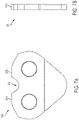
- a front view of the drive link 504 is shown in Figure 7B .
- the abrasive saw chain 500 includes tie straps disposed on the other side of the drive links 504 from the tie straps 502.
- the other tie straps are opposite the tie straps 502 and are coupled with the drive links 504 and tie straps 502 via respective rivets.
- the middle two tie straps 502 are shown in Figure 5 to be transparent to show the structure of the drive links 504.
- the abrasive saw chain 500 further includes cutting elements 514 bonded (e.g., by welding, such as laser welding) to an upper surface 517 of the tie strap 502.
- the cutting elements 514 are further bonded to an upper surface of the respective opposing tie strap (not shown).
- the cutting elements 514 may include diamond and/or another suitable hard and/or abrasive material.
- the upper surface 517 of the tie strap 502 may be substantially flat to facilitate bonding with the cutting element 514.
- a portion 523a-b of an upper surface of the drive links 504 may be substantially coplanar and/or aligned with the upper surface 517 of the tie strap 502 to which the drive link 504 is coupled. Accordingly, the bottom surface of the cutting elements 514 may be in direct contact with the upper surface of the drive links 504. However, the bottom surface of the cutting elements 514 is not bonded to the upper surface of the drive links 504 (e.g., by the welding process). Accordingly, the portions 523a-b of the upper surface may provide support to the cutting elements 514.
- the cutting elements 514 may contact (e.g., be supported by) the portions 523a-b of the upper surface of the drive links 504 while the corresponding tie strap 502 traverses the elongate portion of the guide bar.
- the gap 535 may assist manufacturability, avoid tight joints caused by over-constrained links, and/or permit rotation of the tie straps 502 relative to the drive links 504 when traversing the sprocket.
- the gap 535 may be 0.001 to 0.02 inches (0.03 to 0.5 mm).
- the tie straps 502 may include mating surfaces 537a-b that contact the respective mating surface 537a-b of the adjacent (e.g., forward or rearward) tie strap 502 when the tie straps 502 traverse the elongate portion of the guide bar.
- the mating surfaces 537a-b may be separated from (e.g., not in contact with) the respective mating surface 537a-b when the tie straps 502 are traversing the sprocket.
- the mating surfaces 537a-b may prevent and/or reduce reverse articulation and/or other unwanted movement of the tie straps 502 when the tie straps 502 exit the sprocket and while traversing the elongate portion of the guide bar.
- the mating surfaces 537a-b may form a raised burr from impact loading during articulation.
- the drive links may include a relief gullet 539 that is aligned with the mating surfaces 537a-b to accommodate the raised burr.
- FIGS 8A and 8B illustrate side views of various abrasive saw chain, in accordance with various embodiments.
- the abrasive saw chain 800 includes tie straps 802, cutting drive links 804, and non-cutting drive links 805 coupled to one another via respective rivet holes in an every other alternating pattern.
- the tie straps 802 may include a rear rivet hole 806 that engages with a front rivet hole 808 of a drive link 804 or 805 (e.g., via a rivet (not shown) disposed through the rivet holes 806 and 808).
- the tie straps 802 may further include a forward rivet hole 810 that engages with a rear rivet hole 812 of another drive link 804 or 805 in the abrasive saw chain 800.
- the abrasive saw chain 800 may include tie straps disposed on the other side of the drive links 804, 805 from the tie straps 802.
- the other tie straps may be opposite the tie straps 802 and may be coupled with the drive links 804, 805 and tie straps 802 via respective rivets.
- the abrasive saw chain 800 further includes cutting elements 814 coupled to an upper surface 816 the cutting drive links 804.
- the cutting elements 814 may have a top surface with a central portion 840 that is substantially planar and aligned in the direction of travel, and two end portions 842a-b that are disposed at an angle relative to the central portion 840.
- the cutting elements 814 may include diamond and/or another suitable hard and/or abrasive material.
- the cutting elements 814 may be bonded to the upper surface 816 of the cutting drive links 804, such as by welding.
- a portion 822a-b of an upper surface of the tie straps 802 may be substantially coplanar and/or aligned with the upper surface 816 of the cutting drive links 804 to which the tie strap 802 is coupled. Accordingly, the bottom surface of the cutting elements 814 may be in direct contact with the upper surface of the tie straps 802. However, the bottom surface of the cutting elements 814 are not bonded to the upper surface of the tie straps 802 (e.g., by the welding process).
- the portions 822a-b of the upper surface may provide support to the cutting elements 814.
- the cutting elements 814 may contact (e.g., be supported by) the portions 822a-b of the upper surface of the tie straps 802 while the corresponding cutting drive link 804 traverses the elongate portion of the guide bar.
- the gap 834 may assist manufacturability, avoid tight joints caused by over-constrained links, and/or permit rotation of the tie straps 802 relative to cutting drive link 804 when traversing the sprocket.
- the gap 834 may be 0.001 to 0.02 inches (0.03 to 0.5 mm).
- Such a gap may still support the cutting element, for example via compliance in the chain such that the tie straps 802 and cutter drive links have relative up/down movement with respect to each other.
- the non-cutting drive links 805 in which the cutting elements 814 are coupled can include one or more bumpers 844a-b on the upper surface of non-cutting drive links 805.
- the inclusion of non-cutting drive links 805 with one or more bumpers 844a-b provides for gaps in the cutting surfaces, while maintain stability in in the cut.
- the single and double bumper versions shown are primarily by example.
- the various potential bumper profiles create a relatively smooth transition between cutting elements yet minimize the amount of steel introduced into the cut, which simply causes drag and friction.
- the cutting drive links 804 and the non-cutting drive links 805 may include mating surfaces 846a and 846b, respectively that contact the respective mating surface 846a-b of the adjacent drive links 804, 805 when the drive links 804, 805 traverse the elongate portion of the guide bar.
- the mating surfaces 846a-b may be separated from (e.g., not in contact with) the respective mating surface 846a-b when the drive links 804 are traversing the sprocket.
- the mating surfaces may prevent and/or reduce reverse articulation and/or other unwanted movement of the drive links 804, 805 when the drive links 804, 805 exit the sprocket and while traversing the elongate portion of the guide bar.
- the mating surfaces 846a-b may prevent and/or reduce downward translation of cutting drive link 804 and upward translation of an adjacent non-cutting drive link 805 to constrain reverse articulation and control vertical misalignment of the cutting drive links.
- mating surfaces 846a-b prevent/reduce upward translation and contact at portions 822a-b between cutting element 814 and tie strap 802 prevent/reduce downward translation.
- the mating surface 846a of a drive link extend over the mating surface 846b of an adjacent drive link, for example at an angle of between about 10° and 80°, such as between about 30° and about 60° or about 45°.
- the extensions of the mating surfaces serves to both constrain reverse articulation and control vertical misalignment of the cutting drive links, for example to enhance the chain stability.
- the extensions of the mating surfaces provide a desired translational constraint along with sufficient cross-sectional area between contact surfaces to minimize material deformation and burrs due to impact loading.
- the mating surfaces 846a-b may be included as an alternative to or in addition to the limiting features 124 of the abrasive saw chain 100 discussed above and mating surfaces 236a-b of the abrasive saw chain 200 discussed above. However, in some cases, the mating surfaces 846a-b may form a raised burr from impact loading during articulation. Accordingly, in some embodiments, as shown in Figure 8A and 8B , the tie straps 802 may include a relief gullet 838 that is aligned with the mating surfaces 846a-b to accommodate the raised burr.
- the tie strap 802 may include a chamfer on the upper portion of the inside side edge.
- the chamfer may provide a relief angle to facilitate laser welding of the cutting element 814 to the cutting drive link 804.
- the chamfer on the tie strap 802 may provide a relief angle to allow for clearance should the laser weld between the cutting element 814 and the cutting drive link 804 protrude slightly beyond the first side or the second side of the drive link.
- the tie strap 802 may include a chamfer on one or both inside side edges.
- the cutting drive link 804 may include chamfers on one or both top edges of the cutting drive link 804.
- the chamfers may provide a relief angle to facilitate laser welding of the cutting drive link 804.
- the chamfers may provide a relief angle to prevent or reduce the amount that the laser weld may protrude beyond the first side and/or second side of the drive link.
- the chamfers may extend the length of the top edges of the cutting drive link 804.
- Figure 9A and 9B is a side view of an abrasive saw chain, in accordance with various embodiments.
- the side view and the inset in Figure 9A illustrate a segment of an abrasive chain 900 depicting load sharing contact of a tie strap 902 with a cutting element 914.
- the side view and the inset in Figure 9B illustrate a segment of an abrasive chain 900 depicting upward/downward translation of drive links 904 that enables contact between the bottom side of a cutting element 914 and the top profile of tie strap 902.
- the abrasive saw chain 900 includes tie straps 902 and drive links 904 coupled to one another via respective rivet holes.
- the other tie straps may be opposite the tie straps 902 and may be coupled with the drive links 904 and tie straps 902 via respective rivets.
- the abrasive saw chain 900 further includes cutting elements 914 coupled to an upper surface 916 of the cutting drive links 904. However, the bottom surface of the cutting elements 914 are not bonded to the upper surface of the tie straps 902 (e.g., by the welding process).
- the drive links 904 may include mating surfaces 936a and 936b that contact the respective mating surface 936a-b of the adjacent drive links, for example, when the drive links 904 traverse the elongate portion of the guide bar.
- the mating surfaces 936a-b may be separated from (e.g., not in contact with) the respective mating surface 936a-b when the drive links 904 are traversing the sprocket.
- the mating surfaces may prevent and/or reduce reverse articulation and/or other unwanted movement of the drive links when the drive links 904 exit the sprocket and while traversing the elongate portion of the guide bar.
- a clearance 934 such as a clearance of .001 inches to .010 inches (0.03 to 0.25 mm) to aid chain assembly and facilitate contact for load sharing, between the upper surface of the tie straps 902 and the bottom surface of the cutting elements 914 when the drive links 904 traverse the elongate portion of the guide bar.
- the portions 922a-b of the upper surface may provide support for load sharing between the cutting elements 914, the drive links 904, and the tie straps 902 to distribute the load on the cutting elements 914 across multiple links, and in particular when mating surfaces 936a and 936b are in contact, such as when the drive links 904 traverse the elongate portion of the guide bar.
- the mating surfaces 936a-b may be included as an alternative to or in addition to the limiting features 124 of the abrasive saw chain 100 discussed above, mating surfaces 236a-b of the abrasive saw chain 200, and mating surfaces 846a-b of the abrasive saw chain 800 discussed above.
- the tie strap 902 may include a chamfer on the upper portion of the inside side edge.
- the chamfer may provide a relief angle to facilitate laser welding of the cutting element 914 to the cutting drive link 904.
- the chamfer on the tie strap 902 may provide a relief angle to allow for clearance should the laser weld between the cutting element 914 and the cutting drive link 904 protrude slightly beyond the first side or the second side of the drive link.
- the tie strap 902 may include a chamfer on one or both inside side edges.
- the cutting drive link 904 may include chamfers on one or both top edges of the cutting drive link 904.
- the chamfers may provide a relief angle to facilitate laser welding of the cutting drive link 904.
- the chamfers may provide a relief angle to prevent or reduce the amount that the laser weld may protrude beyond the first side and/or second side of the drive link.
- the chamfers may extend the length of the top edges of the cutting drive link 904.
- Figures 10A and 10B illustrate forward chain articulation.
- Figure 10A is a side view of an abrasive saw chain 900 illustrating allowable forward chain articulation, in accordance with various embodiments.
- Figure 10B is a side view of a conventional chain illustrating forward chain articulation for comparison.
- the minimum bend radius is defined by contact at adjacent corners of the lower surfaces 932a-b of adjacent tie straps.
- the minimum allowable bend radius for forward articulation ranges between about 0.850 inches to about 0.950 inches (21.6 mm to about 24.1 mm).
- a primary benefit of limiting the range of articulation is that tie strap footprint surface area is increased which reduces footprint and guide bar rail wear rates. Reduced wear rates help to maintain stability at chain/bar interface through life.
- the chain re-enters the guide bar groove from the drive sprocket in a more controlled fashion which results in less impact loading on the guide bar rails and generates less vibration in the cutting system.
- Figures 11A and 11B illustrate reverse articulation.
- Figure 11A is a side view of an abrasive saw chain 900 illustrating allowable reverse chain articulation, in accordance with various embodiments.
- Figure 11B is a side view of a conventional chain illustrating reverse chain articulation for comparison.
- contact of the mating surfaces 936a-b of adjacent tie drive links inhibits reverse articulation of the abrasive chain 900.
- Reduced reverse articulation enables cutting loads acting on diamond segments to be distributed evenly across multiple chassis components.
- reduced reverse articulation provides greater stability and reduces vibration which extends the life of the diamond segments.
- Reduced reverse articulation increases guide bar life by spreading wear across more guide bar rail area, prevents unwanted motion of the chain in the cut so the diamond segments maintain consistent and stable contact with the workpiece.
- the chain On elongate portion of guide bar rails, the chain acts more rigidly which promotes cutting efficiency and smoothness.
- a minimum allowable bend radius for reverse articulation is greater than 25 inches (64 cm) is defined by contact between bottom side of segments and upper profile of tie straps, and between adjacent drive links.
- Figure 12 illustrates guide bar 1200 wear patterns from conventional chain and abrasive chain disclosed herein.
- convention chain in which forward and reverse articulation are not limited results in deep concentrated wear patterns on the guide bar rails 1270 (solid line), which decreases the usable life time of the guide bar 1200.
- These localized areas of high bar rail wear may be due to heat and loads generated in rebar cutting.
- using a disclosed chain in which the forward and reverse articulation is limited results in a more even rail wear pattern 1272 (dashed line) in which the wear is distributed along the guide bar 1200.
- Bar rail wear from rebar is evenly distributed across more rail surface area, extending the life of the guide bar 1200. This distribution of the wear provides the guide bar 1200 increased chain stability through life with longer usable life, thereby increasing cutting efficiency and reducing costs to the consumer.
Description
- Embodiments herein relate to the field of chainsaws, and, more specifically, to abrasive saw chain for chainsaws.
- Chainsaws for cutting aggregate materials and/or pipe provide some advantages over alternative cutting devices, such as devices that include circular blades. For example, the chainsaw can perform deep cuts in confined spaces, create square corners without overcuts, and has the ability to cut small, precise openings. However, the chainsaw may require the operator to apply a higher feed load during cutting, may have generally slower cutting speed, and/or may have a shorter usable life for the cutting elements than a cutting device with a circular blade.
-
US4464964 discloses an abrasive saw chain as per the preambles of claims 1 and 14. - Embodiments will be readily understood by the following detailed description in conjunction with the accompanying drawings and the appended claims. Embodiments are illustrated by way of example and not by way of limitation in the figures of the accompanying drawings.
-
Figure 1A illustrates a side view of an abrasive saw chain, in accordance with various embodiments; -
Figure 1B illustrates a side view of a portion of the abrasive saw chain ofFigure 1A as it traverses a sprocket, in accordance with various embodiments; -
Figure 2 illustrates a side view of another abrasive saw chain, in accordance with various embodiments; -
Figure 3A illustrates a side view of a tie strap of the abrasive saw chain ofFigure 2 , in accordance with various embodiments; -
Figure 3B illustrates a front view of the tie strap ofFigure 3A , in accordance with various embodiments; -
Figure 4A illustrates a side view of a drive link of the abrasive saw chain ofFigure 2 , in accordance with various embodiments; -
Figure 4B illustrates a front view of the drive link ofFigure 4A , in accordance with various embodiments; -
Figure 5 illustrates a side view of another abrasive saw chain, in accordance with various embodiments; -
Figure 6A illustrates a side view of a tie strap of the abrasive saw chain ofFigure 5 , in accordance with various embodiments; -
Figure 6B illustrates a front view of the tie strap ofFigure 6A , in accordance with various embodiments; -
Figure 7A illustrates a side view of a drive link of the abrasive saw chain ofFigure 5 , in accordance with various embodiments; -
Figure 7B illustrates a front view of the drive link ofFigure 7A , in accordance with various embodiments; -
Figure 8A illustrates a side view of another abrasive saw chain, in accordance with various embodiments; -
Figure 8B illustrates a side view of another abrasive saw chain, in accordance with various embodiments; -
Figure 9A illustrates a side view and inset view of another abrasive saw chain, in accordance with various embodiments; -
Figure 9B illustrates a side view and inset view of the abrasive saw chain shown inFigure 9A , in accordance with various embodiments; -
Figure 10A illustrates a side view of the abrasive saw chain shown inFigure 9A chain showing allowable forward chain articulation, in accordance with various embodiments; -
Figure 10B illustrates a side view of a conventional chain showing allowable forward chain articulation; -
Figure 11A illustrates a side view of the abrasive saw chain shown inFigure 9A showing allowable reverse chain articulation, in accordance with various embodiments; -
Figure 11B illustrates a side view of a conventional chain showing allowable reverse chain articulation; and -
Figure 12 illustrates guide bar wear patterns for conventional (solid line) and abrasive chain disclosed herein (dashed line). - In the following detailed description, reference is made to the accompanying drawings which form a part hereof, and in which are shown by way of illustration embodiments that may be practiced. It is to be understood that other embodiments may be utilized and structural or logical changes may be made without departing from the scope. Therefore, the following detailed description is not to be taken in a limiting sense, and the scope of embodiments is defined by the appended claims.
- Various operations may be described as multiple discrete operations in turn, in a manner that may be helpful in understanding embodiments; however, the order of description should not be construed to imply that these operations are order dependent.
- The description may use perspective-based descriptions such as up/down, back/front, and top/bottom. Such descriptions are merely used to facilitate the discussion and are not intended to restrict the application of disclosed embodiments.
- The terms "coupled" and "connected," along with their derivatives, may be used. It should be understood that these terms are not intended as synonyms for each other. Rather, in particular embodiments, "connected" may be used to indicate that two or more elements are in direct physical contact with each other. "Coupled" may mean that two or more elements are in direct physical contact. However, "coupled" may also mean that two or more elements are not in direct contact with each other, but yet still cooperate or interact with each other.
- For the purposes of the description, a phrase in the form "A/B" or in the form "A and/or B" means (A), (B), or (A and B). For the purposes of the description, a phrase in the form "at least one of A, B, and C" means (A), (B), (C), (A and B), (A and C), (B and C), or (A, B and C). For the purposes of the description, a phrase in the form "(A)B" means (B) or (AB) that is, A is an optional element.
- The description may use the terms "embodiment" or "embodiments," which may each refer to one or more of the same or different embodiments. Furthermore, the terms "comprising," "including," "having," and the like, as used with respect to embodiments, are synonymous, and are generally intended as "open" terms (e.g., the term "including" should be interpreted as "including but not limited to," the term "having" should be interpreted as "having at least," the term "includes" should be interpreted as "includes but is not limited to," etc.).
- With respect to the use of any plural and/or singular terms herein, those having skill in the art can translate from the plural to the singular and/or from the singular to the plural as is appropriate to the context and/or application. The various singular/plural permutations may be expressly set forth herein for sake of clarity.
- Embodiments herein provide an abrasive saw chain for a chainsaw. The abrasive saw chain may be used to cut aggregate material, such as concrete, brick, etc.; pipe, and/or other hard materials. Abrasive saw chains typically require a wider kerf (cutting width) than cutting blades. The increased kerf width is directly proportional to increased power consumption and requires a higher feed load to be provided by the operator. The links of abrasive saw chains also have some degree of freedom for movement in the pitch, roll, and yaw axes. Such movement occurs not only within the chain, but also at the chain to guide bar interface. The motion generates vibration and impact loads that accelerate wear of the abrasive saw chain (e.g., cutting elements and/or chain chassis) and/or guide bar, and can increase the kerf width.
- In various embodiments, a chainsaw may include a guide bar extending from a body of the chainsaw. The body may include a housing, with a motor disposed inside the housing to drive the saw chain around the guide bar. The guide bar may include a pair of rails, with a groove disposed between the rails. The guide bar may include one or more sprockets at ends of the guide bar, with elongate portions (e.g., straight portions or portions with a slight curvature) disposed between the ends of the guide bar. For example, with respect to the housing, the guide bar may include a drive sprocket at a proximal end of the guide bar and/or a nose sprocket at a distal end of the guide bar.
- Various embodiments described herein provide an abrasive saw chain with one or more features to improve stability and/or performance of the abrasive saw chain. The improved stability may allow less side clearance of the cutting elements relative to the chain chassis and/or guide bar rails, thereby reducing the kerf width and the associated power consumption and feed load. The improved stability may additionally or alternatively provide reduced wear to extend the usable life of the abrasive saw chain (e.g., cutting elements and/or chain chassis) and/or guide bar. The extended usable life provided by improved stability may also allow use of softer cutting elements to improve cutting efficiency and reduce feed load requirements. In some embodiments, the abrasive saw chain may not be designed to cut wood. Saw chain designed for cutting wood typically uses the chain movement, such as porpoising (e.g. wherein the cutter rides up and down), to increase the cutting efficiency of the chain. In a high stability chain, such as those abrasive chains disclosed herein, this type of movement is minimized, making them inefficient for cutting wood.
- In embodiments herein, a disclosed abrasive saw chain has a limited range of articulation, for example, with respect to conventional abrasive saw chain, such as reduced forward and/or reverse articulation. In embodiments, the reduced range of articulation includes reduced forward articulation. By forward articulation, it is meant the degree in which the chain can bend around the radius of a circle, such as a sprocket, the way it would when coupled to a saw or guide bar during conventional operation (see, for example,
Figure 10A ). In embodiments, the minimum forward articulation has a radius from about 0.800 inches (20.3 mm) to about 1.000 inches (25.40 mm), such as about 0.800 inches, 0.850 inches, 0.900 inches, 0.950 inches, or about 1.000 inches (20.3 mm, 21.6 mm, 22.9 mm, 24.1 mm, or about 25.40 mm), such as about 0.850 inches to about 0.950 inches (21.6 mm to about 24.1 mm) in radius. In embodiments, the reduced range of articulation includes reduced reverse articulation. By reverse articulation, it is meant the degree in which the chain can bend around the radius of a circle opposite the way it would when coupled to a saw or guide bar during conventional operation (see, for example,Figure 11A ). In embodiments, the minimum reverse articulation has a radius greater than about 20 inches (51 cm), such as greater than about 20 inches (51 cm), greater than about 21 inches (53 cm), greater than about 22 inches (56 cm), greater than about 23 inches (58 cm), greater than about 24 inches (61 cm), greater than about 25 inches (64 cm), greater than about 26 inches (66 cm), greater than about 27 inches (69 cm), greater than about 28 inches (71 cm), greater than about 29 inches (74 cm), or greater than about 30 inches (76 cm). In some, the minimum reverse articulation is less than about 50 inches (1.3 m). In embodiments, the reduced range of articulation includes both a reduced forward articulation and a reduced reverse articulation. A primary benefit of limiting the range of articulation is that tie strap footprint surface area is increased which reduces footprint and guide bar rail wear rates. Reduced wear rates help to maintain stability at chain/bar interface through life. The chain re-enters the guide bar groove from the drive sprocket in a more controlled fashion which results in less impact loading on the guide bar rails and generates less vibration in the cutting system. Reduced reverse articulation enables cutting loads acting on diamond segments to be distributed evenly across multiple chassis components. In addition, reduced reverse articulation provides greater stability and reduces vibration which extends the life of the diamond segments. Reduced reverse articulation increases guide bar life by spreading wear across more guide bar rail area, prevents unwanted motion of the chain in the cut so the diamond segments maintain consistent and stable contact with the workpiece. On straight portions of guide bar rails, the chain acts more rigidly which promotes cutting efficiency and smoothness. In some embodiments, total articulation, both forward and reverse is reduced by about 55% to about 75% relative to conventional chain that does not include the stability features disclosed herein, for example the total articulation, both forward and reverse is reduced by about 60% to about 70% about 62% to about 68%, or even about 65% and the like. There are significant benefits of limiting the range of articulation. With respect to reduced forward articulation, tie strap footprint surface area is increased which reduces footprint and guide bar rail wear rates. Reduced wear rates help to maintain stability at chain/bar interface through life. In addition, the chain re-enters the guide bar groove from the drive sprocket in a more controlled fashion resulting in less impact loading on the guide bar rails. This also generates less vibration in the cutting system which may allow for more precise cuts and the use of narrower kerf. With respect to reduced reverse articulation, a reduction in reverse articulation enables cutting loads acting on diamond segments to be distributed evenly across multiple chassis components. A reduction of reverse articulation also provides greater stability and reduces vibration which extends the life of the diamond segments. Reduced reverse articulation increases guide bar life by spreading wear across more guide bar rail area, and prevents unwanted motion of the chain in the cut so the diamond segments maintain consistent and stable contact with the workpiece. On straight portions of guide bar rails, the chain acts more rigidly which promotes cutting efficiency and smoothness. - The abrasive saw chain includes a plurality of links coupled to one another, including one or more drive links and/or tie straps. The links may include a pair of rivet holes (e.g., a front rivet hole and a rear rivet hole) to couple the links to respective adjacent links. The drive links may be center links that ride in the groove of the guide bar and/or engage with an internal tooth of the sprockets. The tie straps may be side links (e.g., left-side links or right-side links) that engage with one of the rails of the guide bar. The tie straps may couple successive drive links to one another (e.g., using rivets disposed through the rivet holes of the tie straps and/or drive links, or via another arrangement/coupling).
- In various embodiments, a cutting element may be coupled to an upper surface of some or all of the drive links of the abrasive saw chain. In other embodiments, a cutting element may be coupled to an upper surface of some or all of the tie straps of the abrasive saw chain, for example spanning two opposite tie straps. The cutting element may be any cutting element suitable for cutting the desired material, such as aggregate material and/or pipe. For example, in some embodiments, the cutting element may include diamond segments and/or another suitable hard and/or abrasive material. The cutting elements may extend across an entire width of the abrasive saw chain. For example, the cutting elements may extend laterally to the same extent as the tie straps in both lateral directions, for example so that the chain and/or guide bar can slide into a slot the width of the cutting elements.
- As discussed above, the disclosed abrasive saw chain includes one or more features to improve stability and/or performance of the abrasive saw chain. For example, an upper surface of the tie strap may contact a lower surface of the cutting element to provide support for the cutting element. In some embodiments, the upper surface of the tie strap may contact the lower surface of the cutting element when the tie strap and corresponding drive link traverse the elongate portion of the guide bar and when the tie strap and the drive link traverse the sprocket of the guide bar. Alternatively, the upper surface of the tie strap may contact the lower surface of the cutting element when the tie strap and corresponding drive link traverse the elongate portion of the guide bar, but there may be a gap between the upper surface of the tie strap and the lower surface of the cutting element when the tie strap and the drive link traverse the sprocket of the guide bar. According to the invention, the upper surface of the tie strap contacts and supports the lower surface of the cutting element when the tie strap and the drive link are under load substantially perpendicular to a long axis of the tie strap wherein there is a gap between the upper surface of the tie strap and the lower surface of the cutting element when the tie strap and the drive link are not under load substantially perpendicular to a long axis of the tie strap. In this way, the load applied is effectively shared across multiple links of the chain.
- In some embodiments, the tie strap may include a limiting feature to contact end (front/back) surfaces of adjacent cutting elements when the links traverse an elongate portion of a guide bar. Alternatively, or additionally, the drive links may include a mating surface that contacts a mating surface of an adjacent drive link when the drive links traverse the elongate portion of the guide bar. The limiting feature of the tie straps and/or the mating surfaces of the drive links may prevent rotation (e.g., reverse articulation) of the cutting elements when the drive links exit a sprocket and while traversing the elongate portion of the guide bar. In embodiments, the mating surfaces are substantially perpendicular to a long axis of the guide bar. In embodiments, the mating surfaces of a drive link extend over the mating surfaces of an adjacent drive link, for example at an angle of between about 10° and 80°, such as between about 30° and about 60° or about 45°. The extensions of the mating surfaces serves to both constrain reverse articulation and control vertical misalignment of the cutting drive links, for example to enhance the chain stability. In some embodiments, the extensions of the mating surfaces provide a desired translational constraint along with sufficient cross-sectional area between contact surfaces to minimize material deformation and burrs due to impact loading. Furthermore, one of the benefits of including such mating surfaces is that in applications where water is used, such as the cutting of aggregate, the water is retained in the guide bar, which may reduce the total water consumption needed for cutting.
- In some embodiments, the abrasive saw chain and/or tie straps may be designed such that the lower corners (e.g., defined by the bottom surface and side surface) of adjacent tie straps are within 0.02 inches (0.5 mm) or less of one another when the tie straps traverse the sprocket of the guide bar. When traversing an elongate portion of the guide bar, those same surfaces may be 0.15 inches (3.8 mm) or more from each other. The closeness of the corners may provide a contact area limiting further forward articulation in the event the tie straps over-rotate when traveling around the sprocket, and may increase contact area with the rails of the elongate portion of the guide bar to improve stability and reduce wear.
- In some embodiments, an aspect ratio of the drive links and/or tie straps of the abrasive saw chain (and/or the abrasive saw chain as a whole) may be lower than in conventional saw chains. The aspect ratio may be defined as the ratio of the height of the drive links and/or tie straps compared with the distance between the rivet holes of the respective drive links and/or tie straps. In some embodiments, the height may be measured as the height of the distance that the drive link extends above the rails of the guide bar. In some embodiments, the aspect ratio of the drive links may be 1.0 to 1.15. Additionally, or alternatively, the aspect ratio of the tie straps may be 0.9 to 1.02. For reference, typically conventional chain tie strap aspect ratio is 1.05. These aspect ratio values do not include the height of the cutting element. The reduced aspect ratio of the drive links, tie straps, and/or abrasive saw chain may allow the cutting load to act closer to the guide bar rails, thereby reducing unwanted movement/vibration (e.g., roll, pitch, and/or yaw) of the links for the benefit of increased stability.
- In some embodiments, the aspect ratio of the links and/or abrasive saw chain may be reduced from prior designs without changing the cross-sectional area of material around the rivet holes and/or the hub and flange dimensions of the rivets.
- In various embodiments, the increased stability of the abrasive saw chain provided by the abrasive saw chain described herein may allow the side clearance of the abrasive saw chain to be reduced, which may provide a reduced width for the cutting elements. The side clearance may be the amount that the cutting elements extend laterally past the tie straps and/or the guide bar rails. The reduced width of the cutting elements provides a narrower kerf for cutting which reduces the power consumption of the tool and requires less feed load from the operator. In embodiments, a suitable kerf width is 0.185 inches to 0.205 inches (4.70 mm to 5.21 mm).
-
Figure 1A illustrates anabrasive saw chain 100 in accordance with various embodiments. Additionally,Figure 1B illustrates a portion of theabrasive saw chain 100 as it traverses asprocket 101 of a guide bar. Theabrasive saw chain 100 includes tie straps 102 and drivelinks 104 coupled to one another via respective rivet holes. For example, the tie straps 102 may include arear rivet hole 106 that engages with afront rivet hole 108 of a drive link 104 (e.g., via a rivet (not shown) disposed through the rivet holes 106 and 108). The tie straps 102 may further include aforward rivet hole 110 that engages with arear rivet hole 112 of anotherdrive link 104 in theabrasive saw chain 100. - In some embodiments, the
sprocket 101 shown inFigure 1B may be the drive sprocket of the chainsaw. The drive sprocket may have a smaller pitch diameter compared to the nose sprocket. Accordingly, the maximum forward articulation of theabrasive saw chain 100 may be designed with respect to the pitch diameter of the drive sprocket. - Although not visible in
Figure 1A , theabrasive saw chain 100 may include tie straps disposed on the other side of the drive links 104 from the tie straps 102. The other tie straps may be opposite the tie straps 102 and may be coupled with the drive links 104 and tiestraps 102 via respective rivet holes. - The
abrasive saw chain 100 further includes cuttingelements 114 coupled to anupper surface 116 of the drive links 104. The cuttingelements 114 may include diamond and/or another suitable hard and/or abrasive material. In some embodiments, the cuttingelements 114 may have a top surface with twoportions 118a-b that are substantially planar (either aligned in the direction of travel or disposed at an angle) and separated by anotch 120.Notch 120 is optional both in presence and appearance, but it represents an approach to reducing the surface area of the cutting element contact surface. In some embodiments, the cuttingelements 114 may be bonded to theupper surface 116 of the drive links 104, such as by welding. - In some embodiments, as shown in
Figure 1A , eachdrive link 104 may have acutting element 114 coupled thereto. Such a configuration is known as a "full-house" configuration. In other embodiments, some of the drive links 104 of theabrasive saw chain 100 may have acutting element 114 coupled thereto and someother drive links 104 may not have acutting element 114 coupled thereto, see, for example the embodiments shown inFigures 8A and8B . - In various embodiments, a
portion 122a-b of an upper surface of the tie straps 102 may be substantially coplanar and/or aligned with theupper surface 116 of thedrive link 104 to which thetie strap 102 is coupled. Accordingly, the bottom surface of the cuttingelements 114 may be in direct contact with the upper surface of the tie straps 102. There may be a nominal gap, such as a 0.002 inch (0.051 mm) gap, between the upper surface of the tie straps 102 and the bottom surface of the cuttingelements 114. However, the bottom surface of the cuttingelements 114 is not bonded to the upper surface of the tie straps 102 (e.g., by the welding process). Accordingly, theportions 122a-b of the upper surface may provide support to the cuttingelements 114. - In some embodiments, as shown in
Figures 1A and1B , the cuttingelements 114 may contact (e.g., be supported by) the upper surface of the tie straps 102 while thecorresponding drive link 104 traverses the elongate portion of the guide bar and while thedrive link 104 traverses thesprocket 101 of the guide bar. Such an arrangement may be accomplished by forming a curved transition surface from the upper surface of tie straps 102 to the front and/or back surfaces of tie straps 102. - In various embodiments, the tie straps 102 may further include a limiting
feature 124 that extends above the body of thetie strap 102. The limitingfeature 124 may includemating surfaces 126a-b that contact respective end (front/back) surfaces ofadjacent cutting elements 114. In some embodiments, the mating surfaces 126a-b may contact the front/back surfaces ofadjacent cutting elements 114 when thetie strap 102 andcorresponding drive links 104 are traversing the elongate portion of the guide bar, and the mating surfaces 126a-b may not contact the side surfaces ofadjacent cutting elements 114 when thetie strap 102 andcorresponding drive links 104 are traversing thesprocket 101. The limiting features 124 may prevent and/or reduce reverse articulation and/or other unwanted movement of the drive links 104 while the drive links 104 traverse the elongate portion of the guide bar. - In various embodiments, the limiting
features 124 may includegaps 128a-b between the mating surfaces 126a-b and the upper surface of the tie strap 102 (e.g., theportions 122a-b). Thegaps 128a-b may avoid having a tight fit or misfit of the bottom corners of the cuttingelements 114 against thetie strap 102, which may otherwise cause stress on the links and/or require tight manufacturing tolerances. - In some embodiments, the limiting
features 124 may additionally or alternatively include agap 130 in the top surface of the limitingfeature 124 between the mating surfaces 126a-b. Thegap 130 may allow for the tie strap to use less material than if the limitingfeature 124 did not have a gap. In some cases, during use, the cuttingelements 114 may be worn down to, or below, the height of the limiting features 124. Thegap 130 may reduce the area of the top surface of the limitingfeature 124 that comes into contact with the workpiece when the cuttingelements 114 are worn. - In various embodiments, the
abrasive saw chain 100 and/or tiestraps 102 may be configured to provide an increased contact area between the bottom surface of the tie straps 102 and the guide bar rail compared with conventional saw chains. For example, thecorners 132a-b defined by the bottom surface and respective side surfaces of the tie straps 102 may be positioned so that theadjacent corners 132a-b of adjacent tie straps 102 may be within less than 0.02 inches (0.5 mm) from one another as the tie straps 102 traverse thesprocket 101 of the guide bar. The spacing between adjacent corners may provide increased stability and decreased wear while maintaining the bend radius needed to traverse thesprocket 101. -
Figure 2 illustrates anabrasive saw chain 200 in accordance with various embodiments. Theabrasive saw chain 200 includes tie straps 202 and drivelinks 204 coupled to one another via respective rivet holes. For example, the tie straps 202 may include arear rivet hole 206 that engages with afront rivet hole 208 of a drive link 204 (e.g., via a rivet (not shown) disposed through the rivet holes 206 and 208). The tie straps 202 may further include aforward rivet hole 210 that engages with arear rivet hole 212 of anotherdrive link 204 in theabrasive saw chain 200. - A side view of the
tie strap 202 is shown inFigure 3A , and a front view of thetie strap 202 is shown inFigure 3B . A side view of thedrive link 204 is shown inFigure 4A , and a front view of thedrive link 204 is shown inFigure 4B . Although not visible inFigure 2 , theabrasive saw chain 200 may include tie straps disposed on the other side of the drive links 204 from the tie straps 202. The other tie straps may be opposite the tie straps 202 and may be coupled with the drive links 204 and tiestraps 202 via respective rivets. - The
abrasive saw chain 200 includes cuttingelements 214 coupled to anupper surface 216 of the drive links 204. The cuttingelements 214 may include diamond and/or another suitable hard and/or abrasive material. In some embodiments, the cuttingelements 214 may have a top surface with twoportions 218a-b that are substantially planar (either aligned in the direction of travel or disposed at an angle) and separated by anotch 220. In some embodiments, the cuttingelements 214 may be bonded to theupper surface 216 of the drive links 204, such as by welding. - In various embodiments, a
portion 222a-b of an upper surface of the tie straps 202 may be substantially coplanar and/or aligned with theupper surface 216 of thedrive link 204 to which thetie strap 202 is coupled. Accordingly, the bottom surface of the cuttingelements 214 may be in direct contact with the upper surface of the tie straps 202. There may be a nominal gap, such as a 0.002 inch (0.051 mm) gap, between the upper surface of the tie straps 202 and the bottom surface of the cuttingelements 214. However, the bottom surface of the cuttingelements 214 are not bonded to the upper surface of the tie straps 202 (e.g., by the welding process). Accordingly, theportions 222a-b of the upper surface may provide support to the cuttingelements 214. - As shown in
Figure 2 , the cuttingelements 214 may contact (e.g., be supported by) theportions 222a-b of the upper surface of the tie straps 202 while thecorresponding drive link 204 traverses the elongate portion of the guide bar. However, there may be agap 234 between the bottom surface of the cuttingelements 214 and the upper surface of the tie straps 202 while thedrive link 204 traverses the sprocket of the guide bar (as illustrated by theright-most tie strap 202 and drive link 204 shown inFigure 2 ). Thegap 234 may assist manufacturability, avoid tight joints caused by over-constrained links, and/or permit rotation of the tie straps 202 relative to the drive links 204 when traversing the sprocket (in another example seeFigure 9A ). In some embodiments, thegap 234 may be 0.001 to 0.02 inches (0.03 to 0.5 mm). - In various embodiments, the drive links 204 may include
mating surfaces 236a-b that contact therespective mating surface 236a-b of theadjacent drive link 204 when the drive links 204 traverse the elongate portion of the guide bar. The mating surfaces 236a-b may be separated from (e.g., not in contact with) therespective mating surface 236a-b when the drive links 204 are traversing the sprocket. The mating surfaces may prevent and/or reduce reverse articulation and/or other unwanted movement of the drive links 204 when the drive links 204 exit the sprocket and while traversing the elongate portion of the guide bar. - The mating surfaces 236a-b may be included as an alternative to or in addition to the limiting
features 124 of theabrasive saw chain 100 discussed above. However, in some cases, the mating surfaces 236a-b may form a raised burr from impact loading during articulation. Accordingly, in some embodiments, as shown inFigure 2 , the tie straps 202 may include arelief gullet 238 that is aligned with the mating surfaces 236a-b to accommodate the raised burr. - As seen in
Figure 3B , in some embodiments, thetie strap 202 may include achamfer 240 on the upper portion of the inside side edge. Thechamfer 240 may provide a relief angle to facilitate laser welding of the cuttingelement 214 to thedrive link 204. For example, thechamfer 240 on thetie strap 202 may provide a relief angle to allow for clearance should the laser weld between the cuttingelement 214 and thedrive link 204 protrude slightly beyond the first side or the second side of the drive link. Thetie strap 202 may include achamfer 240 on one or both inside side edges. - As seen in
Figure 4B , in some embodiments thedrive link 204 may includechamfers 242a-b on one or both top edges of thedrive link 204. Thechamfers 242a-b may provide a relief angle to facilitate laser welding of thedrive link 204. For example, thechamfers 242a-b may provide a relief angle to prevent or reduce the amount that the laser weld may protrude beyond the first side and/or second side of the drive link. In some embodiments, thechamfers 242a-b may extend the length of the top edges of thedrive link 204. -
Figure 5 illustrates anabrasive saw chain 500 in which thecutting element 514 is bonded to upper surfaces of an opposing pair of tie straps 502, in accordance with various embodiments. Theabrasive saw chain 500 includes tie straps 502 and drivelinks 504 coupled to one another via respective rivet holes. A side view of thetie strap 502 is shown inFigure 6A , and a front view of thetie strap 502 is shown inFigure 6B . A side view of thedrive link 504 is shown inFigure 7A , and a front view of thedrive link 504 is shown inFigure 7B . - Although not visible in
Figure 5 , theabrasive saw chain 500 includes tie straps disposed on the other side of the drive links 504 from the tie straps 502. The other tie straps are opposite the tie straps 502 and are coupled with the drive links 504 and tiestraps 502 via respective rivets. The middle twotie straps 502 are shown inFigure 5 to be transparent to show the structure of the drive links 504. - The
abrasive saw chain 500 further includes cuttingelements 514 bonded (e.g., by welding, such as laser welding) to anupper surface 517 of thetie strap 502. The cuttingelements 514 are further bonded to an upper surface of the respective opposing tie strap (not shown). The cuttingelements 514 may include diamond and/or another suitable hard and/or abrasive material. In some embodiments, theupper surface 517 of thetie strap 502 may be substantially flat to facilitate bonding with the cuttingelement 514. - In various embodiments, a
portion 523a-b of an upper surface of the drive links 504 may be substantially coplanar and/or aligned with theupper surface 517 of thetie strap 502 to which thedrive link 504 is coupled. Accordingly, the bottom surface of the cuttingelements 514 may be in direct contact with the upper surface of the drive links 504. However, the bottom surface of the cuttingelements 514 is not bonded to the upper surface of the drive links 504 (e.g., by the welding process). Accordingly, theportions 523a-b of the upper surface may provide support to the cuttingelements 514. - In some embodiments, as shown in
Figure 5 , the cuttingelements 514 may contact (e.g., be supported by) theportions 523a-b of the upper surface of the drive links 504 while thecorresponding tie strap 502 traverses the elongate portion of the guide bar. However, there may be agap 535 between the bottom surface of the cuttingelement 514 and the upper surface of thedrive link 504 while thedrive link 504 traverses the sprocket of the guide bar. Thegap 535 may assist manufacturability, avoid tight joints caused by over-constrained links, and/or permit rotation of the tie straps 502 relative to the drive links 504 when traversing the sprocket. In some embodiments, thegap 535 may be 0.001 to 0.02 inches (0.03 to 0.5 mm). - In various embodiments, the tie straps 502 may include
mating surfaces 537a-b that contact therespective mating surface 537a-b of the adjacent (e.g., forward or rearward)tie strap 502 when the tie straps 502 traverse the elongate portion of the guide bar. The mating surfaces 537a-b may be separated from (e.g., not in contact with) therespective mating surface 537a-b when the tie straps 502 are traversing the sprocket. The mating surfaces 537a-b may prevent and/or reduce reverse articulation and/or other unwanted movement of the tie straps 502 when the tie straps 502 exit the sprocket and while traversing the elongate portion of the guide bar. - In some cases, the mating surfaces 537a-b may form a raised burr from impact loading during articulation. Accordingly, in some embodiments, as shown in
Figure 5 , the drive links may include arelief gullet 539 that is aligned with the mating surfaces 537a-b to accommodate the raised burr. -
Figures 8A and8B illustrate side views of various abrasive saw chain, in accordance with various embodiments. Theabrasive saw chain 800 includes tie straps 802, cuttingdrive links 804, and non-cutting drive links 805 coupled to one another via respective rivet holes in an every other alternating pattern. The tie straps 802 may include arear rivet hole 806 that engages with afront rivet hole 808 of adrive link 804 or 805 (e.g., via a rivet (not shown) disposed through the rivet holes 806 and 808). The tie straps 802 may further include aforward rivet hole 810 that engages with arear rivet hole 812 of anotherdrive link abrasive saw chain 800. Although not visible inFigures 8A and8B , theabrasive saw chain 800 may include tie straps disposed on the other side of the drive links 804, 805 from the tie straps 802. The other tie straps may be opposite the tie straps 802 and may be coupled with the drive links 804, 805 and tiestraps 802 via respective rivets. - The
abrasive saw chain 800 further includes cuttingelements 814 coupled to anupper surface 816 the cutting drive links 804. In some embodiments, the cuttingelements 814 may have a top surface with acentral portion 840 that is substantially planar and aligned in the direction of travel, and twoend portions 842a-b that are disposed at an angle relative to thecentral portion 840. - The cutting
elements 814 may include diamond and/or another suitable hard and/or abrasive material. In some embodiments, the cuttingelements 814 may be bonded to theupper surface 816 of the cuttingdrive links 804, such as by welding. In various embodiments, aportion 822a-b of an upper surface of the tie straps 802 may be substantially coplanar and/or aligned with theupper surface 816 of the cuttingdrive links 804 to which thetie strap 802 is coupled. Accordingly, the bottom surface of the cuttingelements 814 may be in direct contact with the upper surface of the tie straps 802. However, the bottom surface of the cuttingelements 814 are not bonded to the upper surface of the tie straps 802 (e.g., by the welding process). Accordingly, theportions 822a-b of the upper surface may provide support to the cuttingelements 814. In some embodiments, as shown inFigures 8A and8B , the cuttingelements 814 may contact (e.g., be supported by) theportions 822a-b of the upper surface of the tie straps 802 while the correspondingcutting drive link 804 traverses the elongate portion of the guide bar. However, there may be agap 834 between the bottom surface of the cuttingelements 814 and the upper surface of the tie straps 802 while the cuttingdrive link 804 traverses the sprocket of the guide bar (as illustrated by the second to theright-most tie strap 802 and cuttingdrive link 804 shown inFigures 8A and8B ). Thegap 834 may assist manufacturability, avoid tight joints caused by over-constrained links, and/or permit rotation of the tie straps 802 relative to cuttingdrive link 804 when traversing the sprocket. In some embodiments, thegap 834 may be 0.001 to 0.02 inches (0.03 to 0.5 mm). In embodiments, there may be a nominal gap, such as a 0.002 inch (0.05 mm) gap, between the upper surface of the tie straps 802 and the bottom surface of the cuttingelements 814. Such a gap may still support the cutting element, for example via compliance in the chain such that the tie straps 802 and cutter drive links have relative up/down movement with respect to each other. - In the embodiments shown, the non-cutting drive links 805 in which the cutting
elements 814 are coupled can include one ormore bumpers 844a-b on the upper surface of non-cutting drive links 805. The inclusion of non-cutting drive links 805 with one ormore bumpers 844a-b provides for gaps in the cutting surfaces, while maintain stability in in the cut. The single and double bumper versions shown are primarily by example. In embodiments, the various potential bumper profiles create a relatively smooth transition between cutting elements yet minimize the amount of steel introduced into the cut, which simply causes drag and friction. - In various embodiments, the cutting
drive links 804 and the non-cutting drive links 805 may includemating surfaces respective mating surface 846a-b of theadjacent drive links respective mating surface 846a-b when the drive links 804 are traversing the sprocket. The mating surfaces may prevent and/or reduce reverse articulation and/or other unwanted movement of the drive links 804, 805 when the drive links 804, 805 exit the sprocket and while traversing the elongate portion of the guide bar. The mating surfaces 846a-b may prevent and/or reduce downward translation of cuttingdrive link 804 and upward translation of an adjacentnon-cutting drive link 805 to constrain reverse articulation and control vertical misalignment of the cutting drive links. With respect to the cutting drive link,mating surfaces 846a-b prevent/reduce upward translation and contact atportions 822a-b between cuttingelement 814 andtie strap 802 prevent/reduce downward translation. The reverse is also true. In embodiments, themating surface 846a of a drive link extend over themating surface 846b of an adjacent drive link, for example at an angle of between about 10° and 80°, such as between about 30° and about 60° or about 45°. The extensions of the mating surfaces serves to both constrain reverse articulation and control vertical misalignment of the cutting drive links, for example to enhance the chain stability. In some embodiments, the extensions of the mating surfaces provide a desired translational constraint along with sufficient cross-sectional area between contact surfaces to minimize material deformation and burrs due to impact loading. - The mating surfaces 846a-b may be included as an alternative to or in addition to the limiting
features 124 of theabrasive saw chain 100 discussed above andmating surfaces 236a-b of theabrasive saw chain 200 discussed above. However, in some cases, the mating surfaces 846a-b may form a raised burr from impact loading during articulation. Accordingly, in some embodiments, as shown inFigure 8A and8B , the tie straps 802 may include arelief gullet 838 that is aligned with the mating surfaces 846a-b to accommodate the raised burr. - In some embodiments, the
tie strap 802 may include a chamfer on the upper portion of the inside side edge. The chamfer may provide a relief angle to facilitate laser welding of the cuttingelement 814 to the cuttingdrive link 804. For example, the chamfer on thetie strap 802 may provide a relief angle to allow for clearance should the laser weld between the cuttingelement 814 and the cuttingdrive link 804 protrude slightly beyond the first side or the second side of the drive link. Thetie strap 802 may include a chamfer on one or both inside side edges. - In some embodiments the cutting
drive link 804 may include chamfers on one or both top edges of the cuttingdrive link 804. The chamfers may provide a relief angle to facilitate laser welding of the cuttingdrive link 804. For example, the chamfers may provide a relief angle to prevent or reduce the amount that the laser weld may protrude beyond the first side and/or second side of the drive link. In some embodiments, the chamfers may extend the length of the top edges of the cuttingdrive link 804. -
Figure 9A and9B is a side view of an abrasive saw chain, in accordance with various embodiments. The side view and the inset inFigure 9A illustrate a segment of anabrasive chain 900 depicting load sharing contact of atie strap 902 with a cuttingelement 914. The side view and the inset inFigure 9B illustrate a segment of anabrasive chain 900 depicting upward/downward translation ofdrive links 904 that enables contact between the bottom side of acutting element 914 and the top profile oftie strap 902. In the embodiment shown, theabrasive saw chain 900 includes tie straps 902 and drivelinks 904 coupled to one another via respective rivet holes. The other tie straps may be opposite the tie straps 902 and may be coupled with the drive links 904 and tiestraps 902 via respective rivets. Theabrasive saw chain 900 further includes cuttingelements 914 coupled to anupper surface 916 of the cutting drive links 904. However, the bottom surface of the cuttingelements 914 are not bonded to the upper surface of the tie straps 902 (e.g., by the welding process). - In various embodiments, the drive links 904 may include
mating surfaces respective mating surface 936a-b of the adjacent drive links, for example, when the drive links 904 traverse the elongate portion of the guide bar. The mating surfaces 936a-b may be separated from (e.g., not in contact with) therespective mating surface 936a-b when the drive links 904 are traversing the sprocket. The mating surfaces may prevent and/or reduce reverse articulation and/or other unwanted movement of the drive links when the drive links 904 exit the sprocket and while traversing the elongate portion of the guide bar. In embodiments there may be aclearance 934, such as a clearance of .001 inches to .010 inches (0.03 to 0.25 mm) to aid chain assembly and facilitate contact for load sharing, between the upper surface of the tie straps 902 and the bottom surface of the cuttingelements 914 when the drive links 904 traverse the elongate portion of the guide bar. Theportions 922a-b of the upper surface may provide support for load sharing between the cuttingelements 914, the drive links 904, and the tie straps 902 to distribute the load on the cuttingelements 914 across multiple links, and in particular when mating surfaces 936a and 936b are in contact, such as when the drive links 904 traverse the elongate portion of the guide bar. The mating surfaces 936a-b may be included as an alternative to or in addition to the limitingfeatures 124 of theabrasive saw chain 100 discussed above,mating surfaces 236a-b of theabrasive saw chain 200, andmating surfaces 846a-b of theabrasive saw chain 800 discussed above. - In some embodiments, the
tie strap 902 may include a chamfer on the upper portion of the inside side edge. The chamfer may provide a relief angle to facilitate laser welding of the cuttingelement 914 to the cuttingdrive link 904. For example, the chamfer on thetie strap 902 may provide a relief angle to allow for clearance should the laser weld between the cuttingelement 914 and the cuttingdrive link 904 protrude slightly beyond the first side or the second side of the drive link. Thetie strap 902 may include a chamfer on one or both inside side edges. - In some embodiments the cutting
drive link 904 may include chamfers on one or both top edges of the cuttingdrive link 904. The chamfers may provide a relief angle to facilitate laser welding of the cuttingdrive link 904. For example, the chamfers may provide a relief angle to prevent or reduce the amount that the laser weld may protrude beyond the first side and/or second side of the drive link. In some embodiments, the chamfers may extend the length of the top edges of the cuttingdrive link 904. -
Figures 10A and 10B illustrate forward chain articulation.Figure 10A is a side view of anabrasive saw chain 900 illustrating allowable forward chain articulation, in accordance with various embodiments.Figure 10B is a side view of a conventional chain illustrating forward chain articulation for comparison. With respect to the abrasive chain shown inFigure 10A , the minimum bend radius is defined by contact at adjacent corners of thelower surfaces 932a-b of adjacent tie straps. The minimum allowable bend radius for forward articulation ranges between about 0.850 inches to about 0.950 inches (21.6 mm to about 24.1 mm). A primary benefit of limiting the range of articulation is that tie strap footprint surface area is increased which reduces footprint and guide bar rail wear rates. Reduced wear rates help to maintain stability at chain/bar interface through life. The chain re-enters the guide bar groove from the drive sprocket in a more controlled fashion which results in less impact loading on the guide bar rails and generates less vibration in the cutting system. -
Figures 11A and 11B illustrate reverse articulation.Figure 11A is a side view of anabrasive saw chain 900 illustrating allowable reverse chain articulation, in accordance with various embodiments.Figure 11B is a side view of a conventional chain illustrating reverse chain articulation for comparison. With respect to the abrasive chain shown inFigure 11A , contact of the mating surfaces 936a-b of adjacent tie drive links inhibits reverse articulation of theabrasive chain 900. Reduced reverse articulation enables cutting loads acting on diamond segments to be distributed evenly across multiple chassis components. In addition reduced reverse articulation provides greater stability and reduces vibration which extends the life of the diamond segments. Reduced reverse articulation increases guide bar life by spreading wear across more guide bar rail area, prevents unwanted motion of the chain in the cut so the diamond segments maintain consistent and stable contact with the workpiece. On elongate portion of guide bar rails, the chain acts more rigidly which promotes cutting efficiency and smoothness. A minimum allowable bend radius for reverse articulation is greater than 25 inches (64 cm) is defined by contact between bottom side of segments and upper profile of tie straps, and between adjacent drive links. -
Figure 12 illustratesguide bar 1200 wear patterns from conventional chain and abrasive chain disclosed herein. As best seen in the inset, convention chain, in which forward and reverse articulation are not limited results in deep concentrated wear patterns on the guide bar rails 1270 (solid line), which decreases the usable life time of theguide bar 1200. These localized areas of high bar rail wear may be due to heat and loads generated in rebar cutting. In contrast, using a disclosed chain in which the forward and reverse articulation is limited results in a more even rail wear pattern 1272 (dashed line) in which the wear is distributed along theguide bar 1200. Bar rail wear from rebar is evenly distributed across more rail surface area, extending the life of theguide bar 1200. This distribution of the wear provides theguide bar 1200 increased chain stability through life with longer usable life, thereby increasing cutting efficiency and reducing costs to the consumer. - Although certain embodiments have been illustrated and described herein, it will be appreciated by those of ordinary skill in the art that a wide variety of alternate and/or equivalent embodiments or implementations calculated to achieve the same purposes may be substituted for the embodiments shown and described without departing from the scope of the appended claims. Those with skill in the art will readily appreciate that embodiments may be implemented in a very wide variety of ways. This application is intended to cover any adaptations or variations of the embodiments discussed herein within the scope of the appended claims. Therefore, it is manifestly intended that embodiments be limited only by the appended claims.
Claims (15)
- An abrasive saw chain (100) comprising:a drive link (104) including an upper surface;a cutting element (114) coupled to the upper surface (116) of the drive link (104), the cutting element (114) having a lower surface extending across a width of the abrasive saw chain (100), the cutting element (114) configured to cut aggregate material or pipe; anda tie strap (102) coupled to the drive link (104), characterized in that the tie strap (102) includes an upper surface to contact and support the lower surface of the cutting element (114) when the tie strap (102) and the drive link (104) are under load substantially perpendicular to a long axis of the tie strap (102), wherein there is a gap between the upper surface of the tie strap (102) and the lower surface of the cutting element (114) when the tie strap (102) and the drive link (104) are not under load substantially perpendicular to a long axis of the tie strap (102) and wherein the upper surface of the tie strap (102) contacts the lower surface of the cutting element (114) when the tie strap (102) and the drive link (104) are under load substantially perpendicular to the long axis of the tie strap (102).
- The abrasive saw chain of claim 1, wherein the drive link (104) is a first drive link and the cutting element (114) is a first element, and wherein the abrasive saw chain (100) further includes:
a second drive link (104) coupled to the first drive link (104) by the tie strap (102), wherein the first drive link (104) includes a mating surface (236a) that contacts a mating surface of the second drive link (104) when the first and second drive links (104) traverse an elongate portion of a guide bar, thereby preventing reverse articulation of the abrasive saw chain (100) below a minimum radius of 20 inches (50.8cm). - The abrasive saw chain of claim 2, wherein the tie strap (102) includes a relief gullet (238) that overlaps with the mating surfaces (236a) of the first and second drive links (104).
- The abrasive saw chain of claim 2, wherein the second drive link (104) comprises a second cutting element (114) coupled to the upper surface of the drive link (104), the cutting element (114) having a lower surface extending across a width of the abrasive saw chain (100), the cutting element (114) configured to cut aggregate material or pipe.
- The abrasive saw chain of claim 2, wherein the second drive link comprises one or more bumpers (844a).
- The abrasive saw chain of claim 5, wherein the mating surfaces (236a) are perpendicular to a long axis of the guide bar.
- The abrasive saw chain of claim 5, wherein the mating surface (236a) of the second drive link (104) extends over the mating surface of the first drive link to control vertical misalignment of the first drive link (104).
- The abrasive saw chain of claim 1, wherein the tie strap (102) includes a limiting feature (124) to contact a front and/or back surface of the cutting element (114) when the tie strap (102) and the drive link (104) traverse an elongate portion of a guide bar, thereby preventing reverse articulation of the abrasive saw chain (100) below a minimum radius of 20 inches (50.8cm).
- The abrasive saw chain of claim 8, wherein the drive link (104) is a first drive link and the cutting element (114) is a first element, and wherein the abrasive saw chain (100) further includes:a second drive link (104) coupled to the first drive link (104) by the tie strap (102); anda second cutting element (114) coupled to an upper surface of the second drive link (104); wherein the limiting feature is further to contact a front and/or back surface of the second cutting element (114) when the tie strap (102) and the first and second drive links (104) traverse the elongate portion of the guide bar.
- The abrasive saw chain of claim 1, wherein the tie strap (102) is a first tie strap and wherein the abrasive saw chain (100) further includes:a second tie strap (102) coupled to the first tie strap (102) by the drive link (104);wherein a corner (132a) defined by a bottom surface and front surface of the first tie strap (102) is disposed less than 0.02 inches (0.508mm) from a corner (132b) of the second tie strap (102) defined by a bottom surface and rear surface of the second tie strap (102) when the first and second tie straps (102) traverse a sprocket of a guide bar.
- The abrasive saw chain of claim 10, where contact between the corner of the first tie strap (102) and the corner of the second tie strap (102) limit forward articulation of the abrasive saw chain (100) to a radius greater than 0.800 inches (2.03cm).
- The abrasive saw chain of claim 1, wherein the aspect ratio of the drive link (104) is between about 1.0 and about 1.15.
- The abrasive saw chain of claim 1, wherein the aspect ratio of the tie strap (102) is about 0.9 and about 1.02.
- An abrasive saw chain (500) comprising:a drive link (504) including an upper surface;a first tie strap (502) and a second tie strap (502) coupled to the drive link (504) and coupled opposite one another, the first and second tie straps (502) including respective upper surfaces;a cutting element (514) configured to cut aggregate material or pipe and extending across a width of the abrasive saw chain (500) and bonded to the upper surfaces of the first and second tie straps (502), the cutting element (514) having a lower surface, characterized in that the drive link (504) including an upper surface to contact and support the lower surface of the cutting element (514) when the first and second tie straps (502) and the drive link (504) are under load substantially perpendicular to a long axis of the first and second tie straps (502), wherein there is a gap between the upper surface of the drive link (504) and the lower surface of the cutting element (514) when the first and second tie straps (502) and the drive link (504) are not under load substantially perpendicular to a long axis of the first and second tie straps (502) and wherein the upper surface of the drive link (504) contacts the lower surface of the cutting element (514) when the first and second tie straps (502) and the drive link (504) are under load substantially perpendicular to the long axis of the first and second tie straps (502).
- An abrasive saw chain as claimed in claim 2, wherein
the tie strap (102) is a first tie strap coupling the first drive link (104) to the second drive link (104); and wherein the abrasive saw chain further includes:
a second tie strap (102) coupled to the first drive link (104) or the second drive link (104), wherein the first tie strap (102) includes an upper surface to contact and support the lower surface of the cutting element (114), wherein there is a gap between the upper surface of the first tie strap (102) and the lower surface of the cutting element (114) when the first tie strap (102) and the first drive link (104) are not under load substantially perpendicular to a long axis of the first tie strap (102) and wherein the upper surface of the first tie strap (102) contacts the lower surface of the cutting element (114) when the first tie strap (102) and the first drive link (104) are under load substantially perpendicular to the long axis of the first tie strap (102), wherein contact between a corner (132a) defined by a bottom surface and front surface of the first tie strap (102) and a corner (132b) of the second tie strap (102) defined by a bottom surface and rear surface of the second tie strap (102) limit forward articulation of the abrasive saw chain (100) to a radius greater than 0.800 (2.03cm) inches.
Priority Applications (1)
| Application Number | Priority Date | Filing Date | Title |
|---|---|---|---|
| EP22193843.4A EP4119316A1 (en) | 2015-12-08 | 2016-12-08 | Abrasive saw chain |
Applications Claiming Priority (2)
| Application Number | Priority Date | Filing Date | Title |
|---|---|---|---|
| US201562264783P | 2015-12-08 | 2015-12-08 | |
| PCT/US2016/065667 WO2017100478A1 (en) | 2015-12-08 | 2016-12-08 | Abrasive saw chain |
Related Child Applications (2)
| Application Number | Title | Priority Date | Filing Date |
|---|---|---|---|
| EP22193843.4A Division EP4119316A1 (en) | 2015-12-08 | 2016-12-08 | Abrasive saw chain |
| EP22193843.4A Division-Into EP4119316A1 (en) | 2015-12-08 | 2016-12-08 | Abrasive saw chain |
Publications (3)
| Publication Number | Publication Date |
|---|---|
| EP3374115A1 EP3374115A1 (en) | 2018-09-19 |
| EP3374115A4 EP3374115A4 (en) | 2019-07-17 |
| EP3374115B1 true EP3374115B1 (en) | 2022-10-26 |
Family
ID=58800194
Family Applications (2)
| Application Number | Title | Priority Date | Filing Date |
|---|---|---|---|
| EP22193843.4A Pending EP4119316A1 (en) | 2015-12-08 | 2016-12-08 | Abrasive saw chain |
| EP16873863.1A Active EP3374115B1 (en) | 2015-12-08 | 2016-12-08 | Abrasive saw chain |
Family Applications Before (1)
| Application Number | Title | Priority Date | Filing Date |
|---|---|---|---|
| EP22193843.4A Pending EP4119316A1 (en) | 2015-12-08 | 2016-12-08 | Abrasive saw chain |
Country Status (7)
| Country | Link |
|---|---|
| US (2) | US9895825B2 (en) |
| EP (2) | EP4119316A1 (en) |
| CN (2) | CN110000426B (en) |
| BR (1) | BR112018011516B1 (en) |
| CA (1) | CA3007986C (en) |
| IL (1) | IL259874A (en) |
| WO (1) | WO2017100478A1 (en) |
Families Citing this family (9)
| Publication number | Priority date | Publication date | Assignee | Title |
|---|---|---|---|---|
| US11273573B2 (en) * | 2016-01-13 | 2022-03-15 | Oregon Tool, Inc. | Saw chain link with one or more oversized rivet holes |
| KR101966552B1 (en) * | 2017-10-20 | 2019-08-13 | 정상은 | Grinding tip for chain saw |
| SE543313C2 (en) * | 2018-10-22 | 2020-11-24 | Husqvarna Ab | Link elements for improved flexible abrasive cutting tools |
| KR102195544B1 (en) * | 2019-06-21 | 2020-12-28 | 정상은 | Chain of chain saw |
| SE543428C2 (en) * | 2019-06-24 | 2021-02-16 | Husqvarna Ab | A rotatable cutting chain work tool, a wall saw arrangement comprising such a work tool, an annular member and a method for producing an annular member |
| WO2021108588A1 (en) * | 2019-11-25 | 2021-06-03 | Milwaukee Electric Tool Corporation | Powered handheld cutting tool |
| WO2021107833A1 (en) * | 2019-11-27 | 2021-06-03 | Husqvarna Ab | A rim -type abrasion cutter drive sprocket, a drive arrangement, an abrasion cutter and a method of driving an abrasion cutting chain of an abrasion cutter |
| EP3865266B1 (en) * | 2020-02-12 | 2023-08-16 | Andreas Stihl AG & Co. KG | Cutting chain for cutting mineral or metallic materials |
| KR20240018357A (en) | 2022-08-02 | 2024-02-13 | 정상은 | Chain of chain saw |
Family Cites Families (34)
| Publication number | Priority date | Publication date | Assignee | Title |
|---|---|---|---|---|
| CA627238A (en) * | 1961-09-12 | Rex Chain Saw Ltd. | Saw chain and tooth therefor | |
| DE937915C (en) * | 1952-09-06 | 1956-01-19 | Andreas Stihl | Saw chain consisting of cutting and reaming teeth |
| US4037403A (en) | 1975-09-15 | 1977-07-26 | Omark Industries, Inc. | Method of making integrated tie strap and rivet assemblies for saw chains |
| US4464964A (en) * | 1979-07-23 | 1984-08-14 | Alexander Carl J | Articulated saw |
| DE3027221A1 (en) | 1980-07-18 | 1982-02-18 | Dolmar Maschinen-Fabrik Gmbh & Co, 2000 Hamburg | BRAKE DEVICE FOR BRAKING THE SAW CHAIN OF A PORTABLE MOTOR CHAIN SAW |
| US4426900A (en) | 1981-10-26 | 1984-01-24 | Kolve Sawchain Company | Saw chain using an improved side cutter tooth |
| US4590836A (en) * | 1983-11-17 | 1986-05-27 | Omark Industries, Inc. | Safety chain for chain saws |
| US4643065A (en) * | 1986-06-02 | 1987-02-17 | Omark Industries, Inc. | Saw chain comprised of safety side links designed for reducing vibration |
| CN2059861U (en) * | 1989-06-14 | 1990-08-01 | 福建省福州市化工机械厂 | Cutting and planing type saw chain |
| US4970789A (en) * | 1989-10-06 | 1990-11-20 | Blount, Inc. | Sprocket nose guide bar for chain saws |
| US5136783A (en) * | 1991-05-23 | 1992-08-11 | Blount, Inc. | Chain saw sprocket |
| US5215072A (en) * | 1992-05-04 | 1993-06-01 | Blount, Inc. | Cutting element and saw chain for cutting aggregate material |
| JP2985925B2 (en) * | 1994-02-09 | 1999-12-06 | 株式会社ミヤナガ | Saw chains for chain saws |
| US6374716B1 (en) * | 2000-02-29 | 2002-04-23 | Blount, Inc. | High speed harvester cutting chain |
| US7293491B2 (en) * | 2005-10-21 | 2007-11-13 | Blount, Inc. | Low vibration saw chain |
| US7713006B2 (en) | 2005-11-16 | 2010-05-11 | Les Equipements Prenbec Inc. | Reversible saw tooth |
| US7836808B2 (en) | 2006-01-23 | 2010-11-23 | Szymanski David A | Safety chain and rotational devices and replaceable teeth therefor |
| US7637192B2 (en) * | 2006-10-26 | 2009-12-29 | Blount, Inc. | Saw chain drive link with tail |
| US8136436B2 (en) | 2006-11-15 | 2012-03-20 | Blount, Inc. | Saw chain link with offset footprint |
| EP2183084B1 (en) | 2007-08-22 | 2016-08-10 | Blount, Inc. | Aggregate saw chain for a hand held chain saw and method of manufacturing the same |
| US8746118B2 (en) * | 2008-07-08 | 2014-06-10 | Blount, Inc. | Chain link sharpening method and apparatus |
| US8651005B2 (en) | 2008-07-09 | 2014-02-18 | Blount, Inc. | Utility chain cutter |
| WO2010090895A1 (en) * | 2009-01-23 | 2010-08-12 | John Michelon | Cutting chain |
| US8256335B1 (en) | 2009-05-21 | 2012-09-04 | Wyatt Canon | Bi-directional chainsaw chain |
| DE102010026324A1 (en) * | 2010-07-07 | 2012-01-12 | Andreas Stihl Ag & Co. Kg | Cutting set of a chainsaw and saw chain |
| EP2663433B1 (en) * | 2011-03-04 | 2016-10-26 | Blount, INC. | Chain link sharpening apparatus |
| DE102012010962A1 (en) | 2011-10-12 | 2013-04-18 | Andreas Stihl Ag & Co. Kg | Cutting chain for hand-operated implement for cutting metal and mineral materials, has upper central connecting links that includes drive tooth which are shaped differently to drive tooth on lower central connecting links |
| GB2495620B (en) * | 2011-10-12 | 2015-12-16 | Stihl Maschf Andreas | Cutting chain for a hand-operated implement |
| US9038519B2 (en) * | 2013-03-14 | 2015-05-26 | Blount, Inc. | Apparatus, method, and system for orienting a saw chain link on a sprocket |
| CN105050779B (en) * | 2013-03-27 | 2018-07-06 | 胡斯华纳有限公司 | Chain saw |
| US10773413B2 (en) * | 2014-11-14 | 2020-09-15 | David A. Szymanski | Saw chain and safely connected links therefor |
| US10195759B2 (en) * | 2015-01-07 | 2019-02-05 | Blount, Inc. | Tie strap with hardened integrated rivet for a saw chain |
| US10406715B2 (en) | 2015-01-30 | 2019-09-10 | Blount, Inc. | Tie rivet for saw chain |
| CN105034177B (en) * | 2015-09-14 | 2017-02-22 | 厦门致力金刚石科技股份有限公司 | Stone cutting saw chain |
-
2016
- 2016-12-08 CA CA3007986A patent/CA3007986C/en active Active
- 2016-12-08 US US15/373,297 patent/US9895825B2/en active Active
- 2016-12-08 WO PCT/US2016/065667 patent/WO2017100478A1/en active Application Filing
- 2016-12-08 EP EP22193843.4A patent/EP4119316A1/en active Pending
- 2016-12-08 CN CN201910340451.2A patent/CN110000426B/en active Active
- 2016-12-08 BR BR112018011516-9A patent/BR112018011516B1/en active IP Right Grant
- 2016-12-08 CN CN201680078480.0A patent/CN108430680B/en active Active
- 2016-12-08 EP EP16873863.1A patent/EP3374115B1/en active Active
-
2018
- 2018-01-11 US US15/868,984 patent/US10343302B2/en active Active
- 2018-06-07 IL IL259874A patent/IL259874A/en active IP Right Grant
Also Published As
| Publication number | Publication date |
|---|---|
| US9895825B2 (en) | 2018-02-20 |
| US20180133926A1 (en) | 2018-05-17 |
| EP3374115A1 (en) | 2018-09-19 |
| CN108430680B (en) | 2019-05-14 |
| CN110000426A (en) | 2019-07-12 |
| EP3374115A4 (en) | 2019-07-17 |
| BR112018011516A2 (en) | 2018-11-21 |
| EP4119316A1 (en) | 2023-01-18 |
| BR112018011516B1 (en) | 2022-11-29 |
| CN108430680A (en) | 2018-08-21 |
| IL259874A (en) | 2018-08-01 |
| US10343302B2 (en) | 2019-07-09 |
| CN110000426B (en) | 2021-03-19 |
| CA3007986C (en) | 2019-03-26 |
| WO2017100478A1 (en) | 2017-06-15 |
| US20170157798A1 (en) | 2017-06-08 |
| CA3007986A1 (en) | 2017-06-15 |
Similar Documents
| Publication | Publication Date | Title |
|---|---|---|
| EP3374115B1 (en) | Abrasive saw chain | |
| CA2666833C (en) | Saw chain link with offset footprint | |
| US9027451B2 (en) | Dresser drive link for saw chain | |
| US8342163B2 (en) | Aggregate cutting saw chain | |
| US20080110316A1 (en) | Saw chain cutting link with taper | |
| EP2496859B1 (en) | Drive link with improved lubrication feature | |
| US20150367433A1 (en) | Saw blade having integrated swarf space | |
| US20070089586A1 (en) | Low vibration saw chain | |
| EP2812165B1 (en) | Dresser link for saw chain | |
| US20160121504A1 (en) | Chain-type cutting assembly | |
| CA2315580A1 (en) | Cutter link having a deformed depth limiter | |
| AU1680597A (en) | Chainsaw guide bar |
Legal Events
| Date | Code | Title | Description |
|---|---|---|---|
| STAA | Information on the status of an ep patent application or granted ep patent |
Free format text: STATUS: THE INTERNATIONAL PUBLICATION HAS BEEN MADE |
|
| PUAI | Public reference made under article 153(3) epc to a published international application that has entered the european phase |
Free format text: ORIGINAL CODE: 0009012 |
|
| STAA | Information on the status of an ep patent application or granted ep patent |
Free format text: STATUS: REQUEST FOR EXAMINATION WAS MADE |
|
| 17P | Request for examination filed |
Effective date: 20180612 |
|
| AK | Designated contracting states |
Kind code of ref document: A1 Designated state(s): AL AT BE BG CH CY CZ DE DK EE ES FI FR GB GR HR HU IE IS IT LI LT LU LV MC MK MT NL NO PL PT RO RS SE SI SK SM TR |
|
| AX | Request for extension of the european patent |
Extension state: BA ME |
|
| DAV | Request for validation of the european patent (deleted) | ||
| DAX | Request for extension of the european patent (deleted) | ||
| REG | Reference to a national code |
Ref country code: DE Ref legal event code: R079 Ref document number: 602016075968 Country of ref document: DE Free format text: PREVIOUS MAIN CLASS: B23D0057020000 Ipc: B28D0001120000 |
|
| A4 | Supplementary search report drawn up and despatched |
Effective date: 20190617 |
|
| RIC1 | Information provided on ipc code assigned before grant |
Ipc: B28D 1/12 20060101AFI20190611BHEP |
|
| RAP3 | Party data changed (applicant data changed or rights of an application transferred) |
Owner name: OREGON TOOL, INC. |
|
| STAA | Information on the status of an ep patent application or granted ep patent |
Free format text: STATUS: EXAMINATION IS IN PROGRESS |
|
| 17Q | First examination report despatched |
Effective date: 20210714 |
|
| STAA | Information on the status of an ep patent application or granted ep patent |
Free format text: STATUS: EXAMINATION IS IN PROGRESS |
|
| GRAP | Despatch of communication of intention to grant a patent |
Free format text: ORIGINAL CODE: EPIDOSNIGR1 |
|
| STAA | Information on the status of an ep patent application or granted ep patent |
Free format text: STATUS: GRANT OF PATENT IS INTENDED |
|
| INTG | Intention to grant announced |
Effective date: 20220510 |
|
| GRAS | Grant fee paid |
Free format text: ORIGINAL CODE: EPIDOSNIGR3 |
|
| GRAA | (expected) grant |
Free format text: ORIGINAL CODE: 0009210 |
|
| STAA | Information on the status of an ep patent application or granted ep patent |
Free format text: STATUS: THE PATENT HAS BEEN GRANTED |
|
| AK | Designated contracting states |
Kind code of ref document: B1 Designated state(s): AL AT BE BG CH CY CZ DE DK EE ES FI FR GB GR HR HU IE IS IT LI LT LU LV MC MK MT NL NO PL PT RO RS SE SI SK SM TR |
|
| REG | Reference to a national code |
Ref country code: GB Ref legal event code: FG4D |
|
| REG | Reference to a national code |
Ref country code: CH Ref legal event code: EP |
|
| REG | Reference to a national code |
Ref country code: AT Ref legal event code: REF Ref document number: 1526740 Country of ref document: AT Kind code of ref document: T Effective date: 20221115 |
|
| REG | Reference to a national code |
Ref country code: DE Ref legal event code: R096 Ref document number: 602016075968 Country of ref document: DE |
|
| REG | Reference to a national code |
Ref country code: IE Ref legal event code: FG4D |
|
| PGFP | Annual fee paid to national office [announced via postgrant information from national office to epo] |
Ref country code: DE Payment date: 20221018 Year of fee payment: 7 |
|
| REG | Reference to a national code |
Ref country code: LT Ref legal event code: MG9D |
|
| REG | Reference to a national code |
Ref country code: SE Ref legal event code: TRGR |
|
| REG | Reference to a national code |
Ref country code: NL Ref legal event code: MP Effective date: 20221026 |
|
| REG | Reference to a national code |
Ref country code: AT Ref legal event code: MK05 Ref document number: 1526740 Country of ref document: AT Kind code of ref document: T Effective date: 20221026 |
|
| PG25 | Lapsed in a contracting state [announced via postgrant information from national office to epo] |
Ref country code: NL Free format text: LAPSE BECAUSE OF FAILURE TO SUBMIT A TRANSLATION OF THE DESCRIPTION OR TO PAY THE FEE WITHIN THE PRESCRIBED TIME-LIMIT Effective date: 20221026 |
|
| PG25 | Lapsed in a contracting state [announced via postgrant information from national office to epo] |
Ref country code: PT Free format text: LAPSE BECAUSE OF FAILURE TO SUBMIT A TRANSLATION OF THE DESCRIPTION OR TO PAY THE FEE WITHIN THE PRESCRIBED TIME-LIMIT Effective date: 20230227 Ref country code: NO Free format text: LAPSE BECAUSE OF FAILURE TO SUBMIT A TRANSLATION OF THE DESCRIPTION OR TO PAY THE FEE WITHIN THE PRESCRIBED TIME-LIMIT Effective date: 20230126 Ref country code: LT Free format text: LAPSE BECAUSE OF FAILURE TO SUBMIT A TRANSLATION OF THE DESCRIPTION OR TO PAY THE FEE WITHIN THE PRESCRIBED TIME-LIMIT Effective date: 20221026 Ref country code: FI Free format text: LAPSE BECAUSE OF FAILURE TO SUBMIT A TRANSLATION OF THE DESCRIPTION OR TO PAY THE FEE WITHIN THE PRESCRIBED TIME-LIMIT Effective date: 20221026 Ref country code: ES Free format text: LAPSE BECAUSE OF FAILURE TO SUBMIT A TRANSLATION OF THE DESCRIPTION OR TO PAY THE FEE WITHIN THE PRESCRIBED TIME-LIMIT Effective date: 20221026 Ref country code: AT Free format text: LAPSE BECAUSE OF FAILURE TO SUBMIT A TRANSLATION OF THE DESCRIPTION OR TO PAY THE FEE WITHIN THE PRESCRIBED TIME-LIMIT Effective date: 20221026 |
|
| PGFP | Annual fee paid to national office [announced via postgrant information from national office to epo] |
Ref country code: CH Payment date: 20230101 Year of fee payment: 7 |
|
| PG25 | Lapsed in a contracting state [announced via postgrant information from national office to epo] |
Ref country code: RS Free format text: LAPSE BECAUSE OF FAILURE TO SUBMIT A TRANSLATION OF THE DESCRIPTION OR TO PAY THE FEE WITHIN THE PRESCRIBED TIME-LIMIT Effective date: 20221026 Ref country code: PL Free format text: LAPSE BECAUSE OF FAILURE TO SUBMIT A TRANSLATION OF THE DESCRIPTION OR TO PAY THE FEE WITHIN THE PRESCRIBED TIME-LIMIT Effective date: 20221026 Ref country code: LV Free format text: LAPSE BECAUSE OF FAILURE TO SUBMIT A TRANSLATION OF THE DESCRIPTION OR TO PAY THE FEE WITHIN THE PRESCRIBED TIME-LIMIT Effective date: 20221026 Ref country code: IS Free format text: LAPSE BECAUSE OF FAILURE TO SUBMIT A TRANSLATION OF THE DESCRIPTION OR TO PAY THE FEE WITHIN THE PRESCRIBED TIME-LIMIT Effective date: 20230226 Ref country code: HR Free format text: LAPSE BECAUSE OF FAILURE TO SUBMIT A TRANSLATION OF THE DESCRIPTION OR TO PAY THE FEE WITHIN THE PRESCRIBED TIME-LIMIT Effective date: 20221026 Ref country code: GR Free format text: LAPSE BECAUSE OF FAILURE TO SUBMIT A TRANSLATION OF THE DESCRIPTION OR TO PAY THE FEE WITHIN THE PRESCRIBED TIME-LIMIT Effective date: 20230127 |
|
| P01 | Opt-out of the competence of the unified patent court (upc) registered |
Effective date: 20230530 |
|
| REG | Reference to a national code |
Ref country code: DE Ref legal event code: R097 Ref document number: 602016075968 Country of ref document: DE |
|
| PG25 | Lapsed in a contracting state [announced via postgrant information from national office to epo] |
Ref country code: SM Free format text: LAPSE BECAUSE OF FAILURE TO SUBMIT A TRANSLATION OF THE DESCRIPTION OR TO PAY THE FEE WITHIN THE PRESCRIBED TIME-LIMIT Effective date: 20221026 Ref country code: RO Free format text: LAPSE BECAUSE OF FAILURE TO SUBMIT A TRANSLATION OF THE DESCRIPTION OR TO PAY THE FEE WITHIN THE PRESCRIBED TIME-LIMIT Effective date: 20221026 Ref country code: EE Free format text: LAPSE BECAUSE OF FAILURE TO SUBMIT A TRANSLATION OF THE DESCRIPTION OR TO PAY THE FEE WITHIN THE PRESCRIBED TIME-LIMIT Effective date: 20221026 Ref country code: DK Free format text: LAPSE BECAUSE OF FAILURE TO SUBMIT A TRANSLATION OF THE DESCRIPTION OR TO PAY THE FEE WITHIN THE PRESCRIBED TIME-LIMIT Effective date: 20221026 Ref country code: CZ Free format text: LAPSE BECAUSE OF FAILURE TO SUBMIT A TRANSLATION OF THE DESCRIPTION OR TO PAY THE FEE WITHIN THE PRESCRIBED TIME-LIMIT Effective date: 20221026 |
|
| REG | Reference to a national code |
Ref country code: BE Ref legal event code: MM Effective date: 20221231 |
|
| PG25 | Lapsed in a contracting state [announced via postgrant information from national office to epo] |
Ref country code: SK Free format text: LAPSE BECAUSE OF FAILURE TO SUBMIT A TRANSLATION OF THE DESCRIPTION OR TO PAY THE FEE WITHIN THE PRESCRIBED TIME-LIMIT Effective date: 20221026 Ref country code: LU Free format text: LAPSE BECAUSE OF NON-PAYMENT OF DUE FEES Effective date: 20221208 Ref country code: AL Free format text: LAPSE BECAUSE OF FAILURE TO SUBMIT A TRANSLATION OF THE DESCRIPTION OR TO PAY THE FEE WITHIN THE PRESCRIBED TIME-LIMIT Effective date: 20221026 |
|
| PLBE | No opposition filed within time limit |
Free format text: ORIGINAL CODE: 0009261 |
|
| STAA | Information on the status of an ep patent application or granted ep patent |
Free format text: STATUS: NO OPPOSITION FILED WITHIN TIME LIMIT |
|
| 26N | No opposition filed |
Effective date: 20230727 |
|
| PG25 | Lapsed in a contracting state [announced via postgrant information from national office to epo] |
Ref country code: IE Free format text: LAPSE BECAUSE OF NON-PAYMENT OF DUE FEES Effective date: 20221208 |
|
| PG25 | Lapsed in a contracting state [announced via postgrant information from national office to epo] |
Ref country code: SI Free format text: LAPSE BECAUSE OF FAILURE TO SUBMIT A TRANSLATION OF THE DESCRIPTION OR TO PAY THE FEE WITHIN THE PRESCRIBED TIME-LIMIT Effective date: 20221026 Ref country code: BE Free format text: LAPSE BECAUSE OF NON-PAYMENT OF DUE FEES Effective date: 20221231 |
|
| PGFP | Annual fee paid to national office [announced via postgrant information from national office to epo] |
Ref country code: GB Payment date: 20231227 Year of fee payment: 8 |
|
| PGFP | Annual fee paid to national office [announced via postgrant information from national office to epo] |
Ref country code: SE Payment date: 20231227 Year of fee payment: 8 Ref country code: FR Payment date: 20231227 Year of fee payment: 8 |
|
| PG25 | Lapsed in a contracting state [announced via postgrant information from national office to epo] |
Ref country code: HU Free format text: LAPSE BECAUSE OF FAILURE TO SUBMIT A TRANSLATION OF THE DESCRIPTION OR TO PAY THE FEE WITHIN THE PRESCRIBED TIME-LIMIT; INVALID AB INITIO Effective date: 20161208 |