EP3373790B1 - Extractor cleaning machine - Google Patents
Extractor cleaning machine Download PDFInfo
- Publication number
- EP3373790B1 EP3373790B1 EP16778560.9A EP16778560A EP3373790B1 EP 3373790 B1 EP3373790 B1 EP 3373790B1 EP 16778560 A EP16778560 A EP 16778560A EP 3373790 B1 EP3373790 B1 EP 3373790B1
- Authority
- EP
- European Patent Office
- Prior art keywords
- fluid
- cleaning
- cleaning chamber
- extractor
- tank
- Prior art date
- Legal status (The legal status is an assumption and is not a legal conclusion. Google has not performed a legal analysis and makes no representation as to the accuracy of the status listed.)
- Active
Links
Images


Classifications
-
- A—HUMAN NECESSITIES
- A47—FURNITURE; DOMESTIC ARTICLES OR APPLIANCES; COFFEE MILLS; SPICE MILLS; SUCTION CLEANERS IN GENERAL
- A47L—DOMESTIC WASHING OR CLEANING; SUCTION CLEANERS IN GENERAL
- A47L11/00—Machines for cleaning floors, carpets, furniture, walls, or wall coverings
- A47L11/29—Floor-scrubbing machines characterised by means for taking-up dirty liquid
- A47L11/30—Floor-scrubbing machines characterised by means for taking-up dirty liquid by suction
-
- A—HUMAN NECESSITIES
- A47—FURNITURE; DOMESTIC ARTICLES OR APPLIANCES; COFFEE MILLS; SPICE MILLS; SUCTION CLEANERS IN GENERAL
- A47L—DOMESTIC WASHING OR CLEANING; SUCTION CLEANERS IN GENERAL
- A47L11/00—Machines for cleaning floors, carpets, furniture, walls, or wall coverings
- A47L11/34—Machines for treating carpets in position by liquid, foam, or vapour, e.g. by steam
-
- A—HUMAN NECESSITIES
- A47—FURNITURE; DOMESTIC ARTICLES OR APPLIANCES; COFFEE MILLS; SPICE MILLS; SUCTION CLEANERS IN GENERAL
- A47L—DOMESTIC WASHING OR CLEANING; SUCTION CLEANERS IN GENERAL
- A47L11/00—Machines for cleaning floors, carpets, furniture, walls, or wall coverings
- A47L11/40—Parts or details of machines not provided for in groups A47L11/02 - A47L11/38, or not restricted to one of these groups, e.g. handles, arrangements of switches, skirts, buffers, levers
- A47L11/4002—Installations of electric equipment
- A47L11/4008—Arrangements of switches, indicators or the like
-
- A—HUMAN NECESSITIES
- A47—FURNITURE; DOMESTIC ARTICLES OR APPLIANCES; COFFEE MILLS; SPICE MILLS; SUCTION CLEANERS IN GENERAL
- A47L—DOMESTIC WASHING OR CLEANING; SUCTION CLEANERS IN GENERAL
- A47L11/00—Machines for cleaning floors, carpets, furniture, walls, or wall coverings
- A47L11/40—Parts or details of machines not provided for in groups A47L11/02 - A47L11/38, or not restricted to one of these groups, e.g. handles, arrangements of switches, skirts, buffers, levers
- A47L11/4013—Contaminants collecting devices, i.e. hoppers, tanks or the like
- A47L11/4016—Contaminants collecting devices, i.e. hoppers, tanks or the like specially adapted for collecting fluids
-
- A—HUMAN NECESSITIES
- A47—FURNITURE; DOMESTIC ARTICLES OR APPLIANCES; COFFEE MILLS; SPICE MILLS; SUCTION CLEANERS IN GENERAL
- A47L—DOMESTIC WASHING OR CLEANING; SUCTION CLEANERS IN GENERAL
- A47L11/00—Machines for cleaning floors, carpets, furniture, walls, or wall coverings
- A47L11/40—Parts or details of machines not provided for in groups A47L11/02 - A47L11/38, or not restricted to one of these groups, e.g. handles, arrangements of switches, skirts, buffers, levers
- A47L11/4036—Parts or details of the surface treating tools
-
- A—HUMAN NECESSITIES
- A47—FURNITURE; DOMESTIC ARTICLES OR APPLIANCES; COFFEE MILLS; SPICE MILLS; SUCTION CLEANERS IN GENERAL
- A47L—DOMESTIC WASHING OR CLEANING; SUCTION CLEANERS IN GENERAL
- A47L11/00—Machines for cleaning floors, carpets, furniture, walls, or wall coverings
- A47L11/40—Parts or details of machines not provided for in groups A47L11/02 - A47L11/38, or not restricted to one of these groups, e.g. handles, arrangements of switches, skirts, buffers, levers
- A47L11/408—Means for supplying cleaning or surface treating agents
- A47L11/4083—Liquid supply reservoirs; Preparation of the agents, e.g. mixing devices
-
- A—HUMAN NECESSITIES
- A47—FURNITURE; DOMESTIC ARTICLES OR APPLIANCES; COFFEE MILLS; SPICE MILLS; SUCTION CLEANERS IN GENERAL
- A47L—DOMESTIC WASHING OR CLEANING; SUCTION CLEANERS IN GENERAL
- A47L11/00—Machines for cleaning floors, carpets, furniture, walls, or wall coverings
- A47L11/40—Parts or details of machines not provided for in groups A47L11/02 - A47L11/38, or not restricted to one of these groups, e.g. handles, arrangements of switches, skirts, buffers, levers
- A47L11/408—Means for supplying cleaning or surface treating agents
- A47L11/4088—Supply pumps; Spraying devices; Supply conduits
Definitions
- the present invention relates to extractor cleaning machines and, more particularly, to self-cleaning extractor cleaning machines.
- extractor cleaning machines include components for applying a fluid to a surface and extracting the fluid from the surface.
- extractor cleaning machines may include a fluid distribution system, an agitator brush, a pump, and a suction fan.
- the agitator brush is used to scrub the surface being cleaned.
- the suction fan generates a vacuum force that draws in fluid, dirt, or waste from the surface being cleaned.
- Some extractor machines include an accessory hose assembly and tools to clean above-floor surfaces.
- the accessory tools may be used for cleaning drapes, steps, and furniture.
- the accessory hose assembly provides a conduit for drawing fluid and dirt from the surface to the extractor and sometimes also distributes cleaning fluid using a pump.
- the invention provides an extractor comprising the combined features of claim 1.
- FIG. 1 illustrates an extractor cleaning machine 20 (hereinafter referred to simply as an "extractor").
- the extractor 20 is typically referred to as a portable, a handheld, or canister-type extractor that is operable to clean a surface such as, for example, a floor.
- the extractor 20 may be, for example, an upright extractor.
- the extractor 20 is adapted to clean a variety of surfaces, such as carpets, upholstery, curtains, hardwood floors, tiles, or the like.
- the extractor 20 typically distributes or sprays a cleaning fluid (e.g., water, sanitizer, detergent, or a mixture of water and sanitizer or detergent) onto the surface to clean the surface.
- the extractor 20 then draws the cleaning fluid and dirt off of the surface, leaving the surface relatively clean.
- a cleaning fluid e.g., water, sanitizer, detergent, or a mixture of water and sanitizer or detergent
- the illustrated extractor 20 includes a housing 22, a supply tank 24 for storing a cleaning fluid, and a recovery tank 26 for storing dirty fluid. Both the supply tank 24 and the recovery tank 26 are carried by the housing 22.
- a handle 28 is coupled to the housing 22 to facilitate moving and carrying the extractor 20.
- the extractor 20 also includes a suction source 29 (shown in broken lines in FIG. 1 ) supported by and disposed within the housing.
- the suction source 29 is driven by a motor 31 (shown schematically in broken lines in FIG. 1 ) that is powered (by line or battery) to selectively drive the suction source 29.
- the suction source 29 is operable to draw the cleaning fluid and dirt from the surface.
- the suction source 29 is in communication with the recovery tank 26 for storing the drawn cleaning fluid and dirt in the recovery tank 26.
- the extractor 20 further includes a hose end 30 in communication with the suction source 29 and moveable relative to the housing 22 ( FIG. 2 ).
- the hose end 30 is extended from the suction source 29 via a hose 32. When left exposed, the hose end 30 is a suction nozzle.
- the hose end 30 may be gripped by an operator for movement of the hose 32 and hose end 30 for cleaning.
- the hose end 30 may include a check valve that inhibits liquid from flowing back out the hose end 30 when the suction source 29 is turned off.
- the check valve may include an elastomeric flap or flaps and the like. In some embodiments, the check valve may include a duckbill type check valve.
- the extractor 20 may include an accessory tool 34 for cleaning the surfaces and when connected to the hose end 30 the accessory tool 34 is in communication with the suction source 29.
- the accessory tool 34 may be stored on the housing 22 when not in use. While in use and attached to the hose end 30, an operator can grip the hose end 30, the accessory tool 34, or both to move the accessory tool 34 for cleaning.
- the accessory tool 34 includes a cleaning head 40 with an intake nozzle 44 that operates as a suction nozzle when connected to the hose end 30 for drawing dirty fluid from a surface.
- the cleaning head 40 includes a non-powered agitator, e.g., a brush 46, to help scrub or otherwise clean a surface.
- the cleaning head 40 of the illustrated embodiment is removable from the accessory tool 34 such that different cleaning heads (i.e., 40a, 40b, etc.) can be used to clean surfaces (e.g., furniture, drapes, steps, etc.).
- the cleaning head 40 may include a motor or turbine-powered agitator and/or removable or non-removable cleaning heads.
- the supply tank 24 of the extractor 20 is removeably coupled to the housing 22.
- the supply tank 24 may be retained via a latch mechanism 48.
- the recovery tank 26 is also removeably coupled to the housing 22.
- the recover tank 26 may be retained via a separate latch mechanism 50.
- the supply tank 24 and the recovery tank 26 can easily be filled and/or emptied by an operator at a remote location.
- the supply tank 24 may include two or more compartments, such as a sanitizing fluid tank 52 for storing a sanitizing fluid, and a cleaning fluid tank 54 for storing a cleaning fluid such as water, detergent, or a mixture of water and detergent.
- a sanitizing fluid tank 52 for storing a sanitizing fluid
- a cleaning fluid tank 54 for storing a cleaning fluid such as water, detergent, or a mixture of water and detergent.
- the sanitizing fluid tank 52 includes a sanitizing fluid inlet 56 to allow sanitizing fluid to enter the sanitizing fluid tank 52, and a sanitizing fluid outlet 58 to discharge sanitizing fluid from the sanitizing fluid tank 52.
- the cleaning fluid tank 54 includes a cleaning fluid inlet 60 to allow cleaning fluid to enter the cleaning fluid tank 54, and a cleaning fluid outlet 62 to discharge cleaning fluid from the cleaning fluid tank 54.
- the sanitizing fluid outlet 58 and the cleaning fluid outlet 62 include valves (not shown) that automatically open when the supply tank 24 is attached to the housing 22 and that automatically close when the supply tank 24 is removed from the housing 22, as in one example, poppet valves.
- one or more of the fluid supply tank 24 and recovery tank 26 are not removeably coupled to the extractor cleaning machine 20, instead being configured for filling and emptying on the extractor 20.
- the extractor 220 includes a container inlet 263 in fluid communication with the cleaning chamber 268, the pump 64, or both, such that a container 265 receivable in the container inlet 263 is the supply tank 224, or is in addition to the supply tank 224.
- the container inlet 263 may be configured to receive a single-use container purchased at a retail or other commercial outlet, or a re-fillable container, or other container for providing fluid to the extractor 220.
- the extractor 220 including its supply tank 224 and fluid delivery system are stated and described using cleaning fluid and sanitizing fluid; however, the extractor 220 is not limited.
- the extractor 320 includes a fluid inlet port 386 in fluid communication with the cleaning chamber 368.
- the cleaning chamber 368 is configured to selectively receive fluid from the supply tank 324, the fluid inlet port 386, or a combination of the supply tank 324 and the fluid inlet port 386.
- the fluid inlet port 386 may be a hose connector configured for connecting a hose from a household plumbing fixture or faucet.
- the fluid inlet port 386 may be configured as a container inlet to receive fluid from a single-use container purchased at a retail or other commercial outlet, or a re-fillable container, or other container for providing fluid to the extractor 320.
- the extractor 20 further includes a fluid delivery system.
- the fluid delivery system includes a pump 64 that is in fluid communication with the supply tank 24 and further in communication with a switch (not shown).
- the switch is configured to deactivate the pump 64 and the suction source 29 in a first state. Otherwise, when the switch is in a second state, the fluid delivery system is enabled to selectively deliver cleaning fluid from the supply tank 24 through the pump 64, such as to the surface to be cleaned, along a first fluid flow path 66, which may include a tube or conduit, and through a distribution nozzle 42.
- the distribution nozzle 42 may be positioned adjacent the hose end 30 for distribution of fluid adjacent the accessory tool 34 when the accessory tool 34 is attached to the hose end 30, for example.
- the distribution nozzle 42 may be independent of the hose 32 attached to the housing 22 or remote from the housing 22.
- the first fluid flow path 66 is supported along the hose 32 in order to be in communication with the distribution nozzle 42 on the hose end 30.
- the hose end 30 includes a trigger 38 that, when depressed, activates the pump 64 to provide cleaning fluid through the distribution nozzle 42 from the supply tank 24.
- a controller is configured to deactivate and activate the pump 64 and the suction source 29 in response to one or more inputs such as the trigger 38 or a mode valve assembly 88 ( FIG. 1 ) being actuated, amount of fluid in the supply tank 24 and/or recovery tank 26, pressure in the system, or other variables.
- the illustrated extractor 20 is configured for the hose 32 to draw fluid from the supply tank 24, and optionally other sources, to flush fluid through the hose 32.
- the extractor 20 further includes a cleaning chamber 68.
- the cleaning chamber 68 is disposed on the housing 22 and is capable of receiving a portion of the hose end 30 ( FIG. 10 ).
- the cleaning chamber 68 is configured to selectively receive fluid, such as one or more of the detergent fluid and the sanitizing fluid along a second fluid flow path 70 of the fluid delivery system.
- the extractor 20 further includes a cleaning chamber valve 72 ( FIG. 8 ) configured to selectively permit introduction of the cleaning fluid into the cleaning chamber 68.
- the cleaning chamber valve 72 includes a valve housing 74 configure to receive at least a portion of the hose end 30, and a plunger 76 that is actuatable between a closed position to inhibit the cleaning fluid from entering the cleaning chamber 68, and an open position to permit the cleaning fluid to enter the cleaning chamber 68.
- the plunger 76 has an outer diameter that is less than the inner diameter of the valve housing 74 such that an annular or other shaped gap exists between the plunger 76 and the valve housing 74.
- the cleaning chamber valve 72 further includes a port that is in communication with the supply tank 24. As shown in FIG. 9 , the port may be integrally formed in a port housing 78.
- a spring 80 of the cleaning chamber valve 72 is interposed between the plunger 76 and a wall or surface opposite the plunger 76, such as the port housing 78 as shown in FIG. 9 , to force the plunger 76 toward the closed position.
- inserting the hose end 30 into the valve housing 74 actuates the plunger 76.
- the hose end 30 moves the plunger 76 toward the open position compressing the spring 80 when the hose end 30 is inserted into the cleaning chamber 68 ( FIG. 10 ).
- the hose end 30 seals against the valve housing 74.
- Suction at the hose end 30 provided by the suction source 29 draws fluid along the second fluid flow path 70 extracting the cleaning fluid from the supply tank 24 and into the cleaning chamber 68.
- the cleaning fluid continues through the hose end 30, the hose 32, and into the recovery tank 26 flushing fluid through the hose end 30 and the hose 32 for purposes of at least partially cleaning the hose 32.
- the plunger 76 may be actuated by an actuator operably connected a switch, lever, controller, or other mechanism for moving the plunger 76 between the closed position and the open position.
- the port housing 78 is welded to, attached to, molded with, or otherwise integral with the valve housing 74.
- the cleaning chamber valve 72 further includes one or more rubber gaskets or O-rings (i.e., a plunger seat gasket 84) to close the cleaning chamber valve 72 when the hose end 30 is not inserted in the cleaning chamber 68.
- Other gaskets or seals may be provided as desired to prevent leakage of the cleaning fluid into or out of the cleaning chamber 68 and maintain suction in the cleaning chamber valve 72 when the hose end 30 is positioned in the cleaning chamber 68 suction and the suction source 29 activated.
- the extractor 20 further includes the mode valve assembly 88.
- the mode valve assembly 88 includes a mechanical valve 92 for selectively switching between a first position corresponding to a first mode (i.e., a deactivated suction mode) in which the suction source 29 is deactivated, a second position corresponding to a second mode (i.e., a wash mode) connecting the fluid delivery system to the cleaning fluid tank 54, and a third position corresponding to a third mode (i.e., a sanitize mode) connecting the fluid delivery system to the sanitizing fluid tank 52.
- a first mode i.e., a deactivated suction mode
- a second mode i.e., a wash mode
- a third mode i.e., a sanitize mode
- the mode valve assembly 88 includes a first inlet port 102 in communication with the sanitizing fluid tank 52, a second inlet port 106 in communication with the cleaning fluid tank 54.
- the mode valve assembly 88 selectively connects the sanitizing fluid tank 52 and the cleaning fluid tank 54 with an outlet port in communication with the fluid flow path 66.
- the mechanical valve 92 of the mode valve assembly 88 includes a valve cap 94, and a valve body 96 coupled to the valve cap 94 for at least partially supporting a first gate valve 98 and a second gate valve 100. As best illustrated in FIG.
- the first gate valve 98 has the inlet port 102 in communication with the supply tank 24, and an outlet port 104 downstream of the inlet port 102 and in communication with the fluid delivery system and the cleaning chamber 68.
- the second gate valve 100 has the inlet port 106 in communication with the supply tank 24, and an outlet port 108 downstream of the inlet port 106 and in communication with the fluid delivery system and the cleaning chamber 68.
- the outlet ports 104, 108 are in communication with each other.
- the first gate valve 98 includes a gate 110
- the second gate valve 100 also includes a gate 112, in which each gate 110, 112 is forced by springs 114, 116 toward a closed position.
- the mode valve assembly 88 includes a mode knob 90 that is user-manipulable and supported by the housing 22 to actuate the valve.
- the mode knob 90 includes a cam body 118 ( FIGS. 13 and 14 ) that protrudes away from the underneath-side of the mode knob 90 toward the valve body 96.
- the cam body 118 is selectively enagageable with the gate 110 of the first gate valve 98 and the gate 112 of the second gate valve 100 such that the cam body 118 is capable of imparting a force on the each gate 98, 110 to actuate each gate 98, 100 toward an open position.
- the mode knob 90 is engageable with a micro-switch 120 (e.g., a limit switch) of the mode valve assembly 88 to electrically communicate with the motor 31 of the suction source 29 and the pump 64 of the fluid delivery system such that the mode knob 90 is capable of activating and deactivating the motor 31 and the pump 64 ( FIG. 11 ).
- the mode knob 90 engages the micro-switch 120 in the first position to deactivate the motor 31 and the pump 64
- the mode knob 90 engages the micro-switch 120 in the second position and third position to activate the motor 31 and the pump 64.
- the micro-switch 120 may be supported by the housing 22 of the extractor 20 and user-manipulable such that an operator can directly depress the micro-switch 120 and control operation of the motor 31 and the pump 64.
- an operator manipulates (e.g., rotates) the mode knob 90 away from the deactivated suction mode, in which the gates 110, 112 of the first gate valve 98 and the second gate valve 100 are forced by the springs 114, 116 in the closed position.
- an operator rotates the mode knob 90 to the wash mode or the sanitize mode, respectively.
- the mode knob 90 is rotated, for example, to the wash mode, the motor 31 and the pump 64 are activated and the cam body 118 moves the gate 110 of the first gate valve 98 toward the open position to permit the detergent fluid to flow through the gate 110 from the cleaning fluid tank 54 while the gate 112 of the second gate valve 100 is in the closed position ( FIG. 13 ).
- the motor 31 and the pump 64 remain activated and the cam body 118 moves the gate 112 of the second gate valve 100 toward the open position to permit the sanitizing fluid to flow through the gate 112 from the sanitizing fluid tank 52 while the gate 110 of the first gate valve 98 is in the closed position ( FIG. 14 ).
- the cleaning fluid i.e., detergent fluid or sanitizing fluid
- the pump 64 may continue to operate, but the cleaning fluid is not discharged from the distribution nozzle 42.
- the suction source 29 simultaneously draws dirty fluid and waste from the surface through the hose end 30 where the recovery tank 26 receives and stores the dirty fluid and waste. However, some dirty fluid and waste may remain on the hose end 30 and/or hose 32 after cleaning the surface. Therefore, the cleaning chamber 68 is provided to wash or flush (e.g., sanitize) the hose end 30 and hose 32 in wash mode or sanitize mode, respectively.
- the plunger 76 moves toward the open position to introduce the cleaning fluid (i.e., the detergent fluid or the sanitizing fluid) into the cleaning chamber 68.
- the cleaning fluid flows through the supply tank 24, the second fluid flow path 70, the port housing 78, and the gap between the plunger 76 and the valve housing 74.
- the cleaning fluid is provided to the cleaning chamber 68 at least partially by gravity and suction from the suction source 29.
- the cleaning fluid may be supplied to the cleaning chamber 68 via the pump 64 of the fluid delivery system, either individually or in combination with suction from the suction source 29.
- FIG. 15 illustrates a portion of the extractor 420 having a cleaning chamber 468 according to another embodiment.
- the extractor 420 is similar to the extractor 20 described above with reference to FIGS. 1-12 , and similar parts have been given the same reference number plus 400. Only differences between the embodiments are described.
- the cleaning chamber 468 of the illustrated embodiment includes a duckbill valve 472 instead of the cleaning chamber valve 72 to selectively permit introduction of the cleaning fluid into the cleaning chamber 468.
- the duckbill valve 472 includes a first end having an opening, and an intermediate portion that converges toward a second end having a flat gate.
- the duckbill valve 472 is disposed within the cleaning chamber 468 in communication with the supply tank 424 via the second fluid flow path 470.
- the flat gate of the duckbill valve 472 is moveable between a closed or "default" position, in which fluid is inhibited to flow (i.e., prevent backflow from the supply tank 424 to the cleaning chamber 468), and an open position, in which fluid is permitted to flow.
- the hose end 430 is inserted in the cleaning chamber 468. Suction at the hose end 430 provided by the suction source draws fluid along the fluid flow path 470 through the duckbill valve. As such, the cleaning fluid is permitted to enter the hose end 430. Alternatively or additionally, the cleaning fluid is supplied to the cleaning chamber 468 via the pump 464 of the fluid delivery system.
- FIG. 17 illustrates a portion of the extractor 520 having a cleaning chamber 568 according to another embodiment.
- the extractor 520 is similar to the extractor 20 described above with reference to FIGS. 1-12 , and similar parts have been given the same reference number plus 500. Only differences between the embodiments are described.
- the cleaning chamber 568 of the illustrated embodiment is in communication with the second fluid flow path 570 and the supply tank 3524 without a valve disposed therebetween.
- the second fluid flow path 570 is open to air.
- the pump 564 does not feed the cleaning fluid to the cleaning chamber 568.
- the suction at the hose end 530 provided by the suction source 29 is utilized for drawing the cleaning fluid from the supply tank 524 to the cleaning chamber 568 when the hose end 530 is disposed in the cleaning chamber 568.
- gravity may work alone or in combination with the suction source 529 to provide a gravity feed of the cleaning fluid into the cleaning chamber 568.
- the pump 564 is a centrifugal pump and is utilized strictly to feed the cleaning fluid along the first fluid flow path 566 toward the accessory tool 534. Occasionally, air may collect in the centrifugal pump 564 which, in turn, requires the pump 564 to be primed (i.e., filled totally with water) prior to operating. Leaving the second fluid flow path 570 open to air enables the pump 564 to be primed with ease.
- the hose end 530 is inserted in the cleaning chamber 568. Subsequently, the suction at the hose end 530 provided by the suction source 529 draws cleaning fluid from the supply tank 524 along the second fluid flow path 570. Cleaning fluid can also be fed along the first fluid flow path 566 via the centrifugal pump 564 toward the surface to be cleaned. Air that is entrained during operation of the centrifugal pump 564 escapes to atmospheric air through the second fluid flow path 570. In other embodiments, suction of the suction source 529 may work in combination with gravity feed to deliver the cleaning fluid to the cleaning chamber 568.
- FIG. 18 illustrates a portion of an extractor 620 having a cleaning chamber 668 according to another embodiment.
- the extractor 620 is similar to the extractor 20 described above with reference to FIGS. 1-12 , and similar parts have been given the same reference number plus 600. Only differences between the embodiments are described.
- the accessory tool 634 operates as the suction nozzle.
- the cleaning chamber 668 receives the accessory tool 634 in its entirety.
- the cleaning chamber 668 may receive only a portion of the accessory tool 634 (e.g., the intake nozzle 644 and agitator 646), in which case is more suitable if the agitator 646 is a rotary brush that spins in response to a turbine that rotates as air is drawn passed the turbine.
- the accessory tool 634 of the illustrated embodiment is mounted vertically within the cleaning chamber 668, the accessory tool 634 may be mounted horizontally within the cleaning chamber 668 or in any other orientation.
- the intake nozzle 644 can be positioned at a low point within the cleaning chamber 668 so as to draw out all of the liquid from the cleaning chamber 668.
- at least one spray jet 669 is in communication with second fluid flow path 670 and provided within the cleaning chamber 668 to direct the cleaning fluid toward the accessory tool 634 to clean the accessory tool 634 and/or the agitator 646 of the accessory tool 634.
- the accessory tool 634 is coupled to the hose end 630 and hose 632, which is further in communication with the suction source 629 and the recovery tank 626.
- the accessory tool 634 is mounted within the cleaning chamber 668.
- the cleaning fluid is expelled from the at least one spray jet 669 toward the accessory tool 634 to clean the accessory tool 634 of waste, and the cleaning fluid and waste is temporarily collected within the cleaning chamber 668.
- the cleaning fluid collected in the cleaning chamber 668 reaches a predetermined height such as along an inclined floor of the chamber 668 (indicated by line 671)
- the cleaning fluid and waste are drawn into the intake nozzle 644 of the accessory tool 634 (indicated by arrows 673).
- the accessory tool 634, the intake nozzle 644, and the hose 632 are cleaned simultaneously, while the cleaning fluid and waste are discharged into the recovery tank 626.
- FIG. 19 illustrates a portion of the extractor 720 having a cleaning chamber 768 according to an alternative embodiment.
- the extractor 720 is similar to the extractor 620 described above with reference to FIG. 18 , and similar parts have been given the same reference number plus 100. Only differences between the embodiments are described.
- the accessory tool 734 is a plurality of accessory tools that are received within the cleaning chamber 768 to clean the accessory tools 734 of waste.
- the hose end 730 and hose 732 are coupled to the cleaning chamber 768 via a drain reservoir 775, such that the hose 732 does not connect to either of the accessory tools 734.
- the accessory tools 734 may be connected together and to the hose 732 via a split or T-hose in a similar construction to the embodiment of FIG. 18 .
- the fluid expelled from the at least spray jet 769 toward the plurality of accessory tools 734 is collected in the cleaning chamber 768.
- the cleaning fluid and waste that is collected in the cleaning chamber 768 is drawn out of the cleaning chamber 768 through the drain reservoir 775. Subsequently, the cleaning fluid and waste flows through the hose 732 and expelled and stored in the recovery tank 726.
- the invention provides, among other things, a self-cleaning system for an extractor cleaning machine.
Landscapes
- Cleaning By Liquid Or Steam (AREA)
- Cleaning In General (AREA)
Description
- The present invention relates to extractor cleaning machines and, more particularly, to self-cleaning extractor cleaning machines.
- Typically, extractor cleaning machines include components for applying a fluid to a surface and extracting the fluid from the surface. For example, extractor cleaning machines may include a fluid distribution system, an agitator brush, a pump, and a suction fan. The agitator brush is used to scrub the surface being cleaned. The suction fan generates a vacuum force that draws in fluid, dirt, or waste from the surface being cleaned. Some extractor machines include an accessory hose assembly and tools to clean above-floor surfaces. For example, the accessory tools may be used for cleaning drapes, steps, and furniture. The accessory hose assembly provides a conduit for drawing fluid and dirt from the surface to the extractor and sometimes also distributes cleaning fluid using a pump.
-
US2013/318741 A1 teaches a prior art cleaning apparatus. - In one embodiment, the invention provides an extractor comprising the combined features of claim 1.
- Other aspects of the invention will become apparent by consideration of the detailed description and accompanying drawings.
-
-
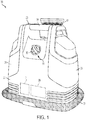
FIG. 1 is a front perspective view of an extractor in accordance with one embodiment of the invention. -
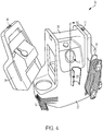
FIG. 2 is a rear perspective view of the extractor ofFIG. 1 . -
FIG. 3 is a perspective view of an accessory tool of the extractor ofFIG. 1 . -
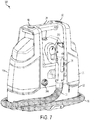
FIG. 4 is a perspective view of the extractor ofFIG. 1 , illustrating a supply tank removed from a housing of the extractor. -
FIG. 5 is a schematic view of a portion of the extractor ofFIG. 1 , illustrating a supply tank, a mode valve assembly, and a cleaning chamber. -
FIG. 6 is a perspective view of an extractor in accordance with another embodiment of the invention. -
FIG. 7 is a perspective view of an extractor in accordance with another embodiment of the invention. -
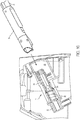
FIG. 8 is an exploded perspective view of the cleaning chamber valve of the extractor ofFIG. 1 . -
FIG. 9 is a cross-sectional perspective view of the cleaning chamber valve ofFIG. 8 . -
FIG. 10 is a cross-sectional view of a portion of the extractor taken along line 10-10 ofFIG. 4 , illustrating a suction nozzle being inserted into the cleaning chamber. -
FIG. 11 is an exploded view of the mode valve assembly of the extractor ofFIG. 1 . -
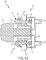
FIG. 12 is a cross-section view of the mode valve assembly taken along line 12-12 ofFIG. 11 , illustrating the mode valve assembly in a first position. -
FIG. 13 is a similar cross-section view asFIG. 12 , illustrating the mode valve assembly in a second position. -
FIG. 14 is a similar cross-section view asFIG. 12 , illustrating the mode valve assembly in a third position. -
FIG. 15 is a schematic of a portion of an extractor according to another embodiment of the invention. -
FIG. 16 is a cross-section view of a portion of the extractor ofFIG. 15 . -
FIG. 17 is a schematic of a portion of an extractor according to another embodiment of the invention. -
FIG. 18 is a schematic of a portion of an extractor according to another embodiment of the invention. -
FIG. 19 is a schematic of a portion of an extractor according to another embodiment of the invention. - Before any embodiments of the invention are explained in detail, it is to be understood that the invention is not limited in its application to the details of construction and the arrangement of components set forth in the following description or illustrated in the following drawings. The invention is capable of other embodiments and of being practiced or of being carried out in various ways. Also, it is to be understood that the phraseology and terminology used herein is for the purpose of description and should not be regarded as limiting. Use of "including" and "comprising" and variations thereof as used herein is meant to encompass the items listed thereafter and equivalents thereof as well as additional items. Use of "consisting of" and variations thereof as used herein is meant to encompass only the items listed thereafter and equivalents thereof. Unless specified or limited otherwise, the terms "mounted," "connected," "supported," and "coupled" and variations thereof are used broadly and encompass both direct and indirect mountings, connections, supports, and couplings.
-
FIG. 1 illustrates an extractor cleaning machine 20 (hereinafter referred to simply as an "extractor"). In the illustrated embodiment, theextractor 20 is typically referred to as a portable, a handheld, or canister-type extractor that is operable to clean a surface such as, for example, a floor. In other embodiments, theextractor 20 may be, for example, an upright extractor. In some embodiments, theextractor 20 is adapted to clean a variety of surfaces, such as carpets, upholstery, curtains, hardwood floors, tiles, or the like. Theextractor 20 typically distributes or sprays a cleaning fluid (e.g., water, sanitizer, detergent, or a mixture of water and sanitizer or detergent) onto the surface to clean the surface. Theextractor 20 then draws the cleaning fluid and dirt off of the surface, leaving the surface relatively clean. - The illustrated
extractor 20 includes ahousing 22, asupply tank 24 for storing a cleaning fluid, and arecovery tank 26 for storing dirty fluid. Both thesupply tank 24 and therecovery tank 26 are carried by thehousing 22. Ahandle 28 is coupled to thehousing 22 to facilitate moving and carrying theextractor 20. Theextractor 20 also includes a suction source 29 (shown in broken lines inFIG. 1 ) supported by and disposed within the housing. The suction source 29 is driven by a motor 31 (shown schematically in broken lines inFIG. 1 ) that is powered (by line or battery) to selectively drive the suction source 29. The suction source 29 is operable to draw the cleaning fluid and dirt from the surface. Specifically, the suction source 29 is in communication with therecovery tank 26 for storing the drawn cleaning fluid and dirt in therecovery tank 26. Theextractor 20 further includes ahose end 30 in communication with the suction source 29 and moveable relative to the housing 22 (FIG. 2 ). Thehose end 30 is extended from the suction source 29 via ahose 32. When left exposed, thehose end 30 is a suction nozzle. Thehose end 30 may be gripped by an operator for movement of thehose 32 andhose end 30 for cleaning. Thehose end 30 may include a check valve that inhibits liquid from flowing back out thehose end 30 when the suction source 29 is turned off. The check valve may include an elastomeric flap or flaps and the like. In some embodiments, the check valve may include a duckbill type check valve. - With reference to
FIGS. 2 and3 , theextractor 20 may include anaccessory tool 34 for cleaning the surfaces and when connected to thehose end 30 theaccessory tool 34 is in communication with the suction source 29. In one embodiment illustrated inFIG. 2 , theaccessory tool 34 may be stored on thehousing 22 when not in use. While in use and attached to thehose end 30, an operator can grip thehose end 30, theaccessory tool 34, or both to move theaccessory tool 34 for cleaning. Theaccessory tool 34 includes a cleaning head 40 with anintake nozzle 44 that operates as a suction nozzle when connected to thehose end 30 for drawing dirty fluid from a surface. In the illustrated embodiment, the cleaning head 40 includes a non-powered agitator, e.g., a brush 46, to help scrub or otherwise clean a surface. Also, the cleaning head 40 of the illustrated embodiment is removable from theaccessory tool 34 such that different cleaning heads (i.e., 40a, 40b, etc.) can be used to clean surfaces (e.g., furniture, drapes, steps, etc.). In other embodiments, the cleaning head 40 may include a motor or turbine-powered agitator and/or removable or non-removable cleaning heads. - With reference to
FIGS. 4 and5 , thesupply tank 24 of theextractor 20 is removeably coupled to thehousing 22. Thesupply tank 24 may be retained via a latch mechanism 48. Similarly, therecovery tank 26 is also removeably coupled to thehousing 22. The recovertank 26 may be retained via aseparate latch mechanism 50. As such, thesupply tank 24 and therecovery tank 26 can easily be filled and/or emptied by an operator at a remote location. Optionally, as in the embodiment shown inFIG. 5 , thesupply tank 24 may include two or more compartments, such as a sanitizingfluid tank 52 for storing a sanitizing fluid, and a cleaningfluid tank 54 for storing a cleaning fluid such as water, detergent, or a mixture of water and detergent. As best illustrated inFIG. 5 , the sanitizingfluid tank 52 includes a sanitizingfluid inlet 56 to allow sanitizing fluid to enter the sanitizingfluid tank 52, and a sanitizingfluid outlet 58 to discharge sanitizing fluid from the sanitizingfluid tank 52. Similarly, the cleaningfluid tank 54 includes a cleaningfluid inlet 60 to allow cleaning fluid to enter the cleaningfluid tank 54, and a cleaningfluid outlet 62 to discharge cleaning fluid from the cleaningfluid tank 54. The sanitizingfluid outlet 58 and the cleaningfluid outlet 62 include valves (not shown) that automatically open when thesupply tank 24 is attached to thehousing 22 and that automatically close when thesupply tank 24 is removed from thehousing 22, as in one example, poppet valves. In another embodiment, one or more of thefluid supply tank 24 andrecovery tank 26 are not removeably coupled to theextractor cleaning machine 20, instead being configured for filling and emptying on theextractor 20. - In the embodiment shown in
FIG. 6 , theextractor 220 includes acontainer inlet 263 in fluid communication with thecleaning chamber 268, thepump 64, or both, such that acontainer 265 receivable in thecontainer inlet 263 is thesupply tank 224, or is in addition to thesupply tank 224. Thecontainer inlet 263 may be configured to receive a single-use container purchased at a retail or other commercial outlet, or a re-fillable container, or other container for providing fluid to theextractor 220. For convenience, theextractor 220 including itssupply tank 224 and fluid delivery system are stated and described using cleaning fluid and sanitizing fluid; however, theextractor 220 is not limited. All of the components of theextractor 220 may be configured to provide water, detergent, stain releaser, cleaner, sanitizer, maintainers, finishes, other fluids, or any mixture or mixtures thereof. In other embodiments such asFIG. 7 , theextractor 320 includes afluid inlet port 386 in fluid communication with thecleaning chamber 368. In this embodiment, thecleaning chamber 368 is configured to selectively receive fluid from thesupply tank 324, thefluid inlet port 386, or a combination of thesupply tank 324 and thefluid inlet port 386. Thefluid inlet port 386 may be a hose connector configured for connecting a hose from a household plumbing fixture or faucet. Alternatively, thefluid inlet port 386 may be configured as a container inlet to receive fluid from a single-use container purchased at a retail or other commercial outlet, or a re-fillable container, or other container for providing fluid to theextractor 320. - With continued reference to
FIG. 5 , theextractor 20 further includes a fluid delivery system. The fluid delivery system includes apump 64 that is in fluid communication with thesupply tank 24 and further in communication with a switch (not shown). The switch is configured to deactivate thepump 64 and the suction source 29 in a first state. Otherwise, when the switch is in a second state, the fluid delivery system is enabled to selectively deliver cleaning fluid from thesupply tank 24 through thepump 64, such as to the surface to be cleaned, along a first fluid flow path 66, which may include a tube or conduit, and through adistribution nozzle 42. Thedistribution nozzle 42 may be positioned adjacent thehose end 30 for distribution of fluid adjacent theaccessory tool 34 when theaccessory tool 34 is attached to thehose end 30, for example. Alternatively, thedistribution nozzle 42 may be independent of thehose 32 attached to thehousing 22 or remote from thehousing 22. In the illustrated embodiment, the first fluid flow path 66 is supported along thehose 32 in order to be in communication with thedistribution nozzle 42 on thehose end 30. As shown inFIG. 3 , thehose end 30 includes atrigger 38 that, when depressed, activates thepump 64 to provide cleaning fluid through thedistribution nozzle 42 from thesupply tank 24. In an alternative embodiment, a controller is configured to deactivate and activate thepump 64 and the suction source 29 in response to one or more inputs such as thetrigger 38 or a mode valve assembly 88 (FIG. 1 ) being actuated, amount of fluid in thesupply tank 24 and/orrecovery tank 26, pressure in the system, or other variables. - The illustrated
extractor 20 is configured for thehose 32 to draw fluid from thesupply tank 24, and optionally other sources, to flush fluid through thehose 32. With reference toFIGS. 8-10 , theextractor 20 further includes acleaning chamber 68. The cleaningchamber 68 is disposed on thehousing 22 and is capable of receiving a portion of the hose end 30 (FIG. 10 ). The cleaningchamber 68 is configured to selectively receive fluid, such as one or more of the detergent fluid and the sanitizing fluid along a secondfluid flow path 70 of the fluid delivery system. Theextractor 20 further includes a cleaning chamber valve 72 (FIG. 8 ) configured to selectively permit introduction of the cleaning fluid into the cleaningchamber 68. The cleaningchamber valve 72 includes avalve housing 74 configure to receive at least a portion of thehose end 30, and aplunger 76 that is actuatable between a closed position to inhibit the cleaning fluid from entering the cleaningchamber 68, and an open position to permit the cleaning fluid to enter thecleaning chamber 68. In the illustrated embodiment, theplunger 76 has an outer diameter that is less than the inner diameter of thevalve housing 74 such that an annular or other shaped gap exists between theplunger 76 and thevalve housing 74. The cleaningchamber valve 72 further includes a port that is in communication with thesupply tank 24. As shown inFIG. 9 , the port may be integrally formed in aport housing 78. Aspring 80 of thecleaning chamber valve 72 is interposed between theplunger 76 and a wall or surface opposite theplunger 76, such as theport housing 78 as shown inFIG. 9 , to force theplunger 76 toward the closed position. In the illustrated embodiment, inserting thehose end 30 into thevalve housing 74 actuates theplunger 76. Thehose end 30 moves theplunger 76 toward the open position compressing thespring 80 when thehose end 30 is inserted into the cleaning chamber 68 (FIG. 10 ). In one alternative, not shown, the hose end 30 seals against thevalve housing 74. Suction at thehose end 30 provided by the suction source 29 draws fluid along the secondfluid flow path 70 extracting the cleaning fluid from thesupply tank 24 and into the cleaningchamber 68. In turn, the cleaning fluid continues through thehose end 30, thehose 32, and into therecovery tank 26 flushing fluid through thehose end 30 and thehose 32 for purposes of at least partially cleaning thehose 32. In alternative embodiments, theplunger 76 may be actuated by an actuator operably connected a switch, lever, controller, or other mechanism for moving theplunger 76 between the closed position and the open position. In alternative embodiments, theport housing 78 is welded to, attached to, molded with, or otherwise integral with thevalve housing 74. - The cleaning
chamber valve 72 further includes one or more rubber gaskets or O-rings (i.e., a plunger seat gasket 84) to close the cleaningchamber valve 72 when thehose end 30 is not inserted in thecleaning chamber 68. Other gaskets or seals (not shown) may be provided as desired to prevent leakage of the cleaning fluid into or out of the cleaningchamber 68 and maintain suction in thecleaning chamber valve 72 when thehose end 30 is positioned in thecleaning chamber 68 suction and the suction source 29 activated. - With reference to
FIGS. 11-14 , theextractor 20 further includes themode valve assembly 88. Themode valve assembly 88 includes amechanical valve 92 for selectively switching between a first position corresponding to a first mode (i.e., a deactivated suction mode) in which the suction source 29 is deactivated, a second position corresponding to a second mode (i.e., a wash mode) connecting the fluid delivery system to the cleaningfluid tank 54, and a third position corresponding to a third mode (i.e., a sanitize mode) connecting the fluid delivery system to the sanitizingfluid tank 52. Themode valve assembly 88 includes afirst inlet port 102 in communication with the sanitizingfluid tank 52, asecond inlet port 106 in communication with the cleaningfluid tank 54. Themode valve assembly 88 selectively connects the sanitizingfluid tank 52 and the cleaningfluid tank 54 with an outlet port in communication with the fluid flow path 66. In the illustrated embodiment, themechanical valve 92 of themode valve assembly 88 includes avalve cap 94, and avalve body 96 coupled to thevalve cap 94 for at least partially supporting afirst gate valve 98 and asecond gate valve 100. As best illustrated inFIG. 12 , thefirst gate valve 98 has theinlet port 102 in communication with thesupply tank 24, and anoutlet port 104 downstream of theinlet port 102 and in communication with the fluid delivery system and thecleaning chamber 68. Similarly, thesecond gate valve 100 has theinlet port 106 in communication with thesupply tank 24, and anoutlet port 108 downstream of theinlet port 106 and in communication with the fluid delivery system and thecleaning chamber 68. Theoutlet ports first gate valve 98 includes agate 110, and thesecond gate valve 100 also includes agate 112, in which eachgate springs mode valve assembly 88 includes amode knob 90 that is user-manipulable and supported by thehousing 22 to actuate the valve. - The
mode knob 90 includes a cam body 118 (FIGS. 13 and 14 ) that protrudes away from the underneath-side of themode knob 90 toward thevalve body 96. Thecam body 118 is selectively enagageable with thegate 110 of thefirst gate valve 98 and thegate 112 of thesecond gate valve 100 such that thecam body 118 is capable of imparting a force on the eachgate gate mode knob 90 is engageable with a micro-switch 120 (e.g., a limit switch) of themode valve assembly 88 to electrically communicate with themotor 31 of the suction source 29 and thepump 64 of the fluid delivery system such that themode knob 90 is capable of activating and deactivating themotor 31 and the pump 64 (FIG. 11 ). Specifically, themode knob 90 engages the micro-switch 120 in the first position to deactivate themotor 31 and thepump 64, whereas themode knob 90 engages the micro-switch 120 in the second position and third position to activate themotor 31 and thepump 64. In other embodiments, themicro-switch 120 may be supported by thehousing 22 of theextractor 20 and user-manipulable such that an operator can directly depress themicro-switch 120 and control operation of themotor 31 and thepump 64. - During use, an operator manipulates (e.g., rotates) the
mode knob 90 away from the deactivated suction mode, in which thegates first gate valve 98 and thesecond gate valve 100 are forced by thesprings mode knob 90 to the wash mode or the sanitize mode, respectively. When themode knob 90 is rotated, for example, to the wash mode, themotor 31 and thepump 64 are activated and thecam body 118 moves thegate 110 of thefirst gate valve 98 toward the open position to permit the detergent fluid to flow through thegate 110 from the cleaningfluid tank 54 while thegate 112 of thesecond gate valve 100 is in the closed position (FIG. 13 ). Conversely, when an operator rotates themode knob 90, for example, to the sanitize mode, themotor 31 and thepump 64 remain activated and thecam body 118 moves thegate 112 of thesecond gate valve 100 toward the open position to permit the sanitizing fluid to flow through thegate 112 from the sanitizingfluid tank 52 while thegate 110 of thefirst gate valve 98 is in the closed position (FIG. 14 ). As such, the cleaning fluid (i.e., detergent fluid or sanitizing fluid) flows along the first fluid path 66 and is pumped by thepump 64 onto the surface to be cleaned through the distribution nozzle 42 (if thetrigger 38 is depressed). If thetrigger 38 is not depressed, thepump 64 may continue to operate, but the cleaning fluid is not discharged from thedistribution nozzle 42. The suction source 29 simultaneously draws dirty fluid and waste from the surface through thehose end 30 where therecovery tank 26 receives and stores the dirty fluid and waste. However, some dirty fluid and waste may remain on thehose end 30 and/orhose 32 after cleaning the surface. Therefore, the cleaningchamber 68 is provided to wash or flush (e.g., sanitize) thehose end 30 andhose 32 in wash mode or sanitize mode, respectively. - In order to wash or flush the
hose end 30, an operator inserts thehose end 30 into the cleaningchamber 68. Subsequently, theplunger 76 moves toward the open position to introduce the cleaning fluid (i.e., the detergent fluid or the sanitizing fluid) into the cleaningchamber 68. The cleaning fluid flows through thesupply tank 24, the secondfluid flow path 70, theport housing 78, and the gap between theplunger 76 and thevalve housing 74. The cleaning fluid is provided to thecleaning chamber 68 at least partially by gravity and suction from the suction source 29. In other embodiments, the cleaning fluid may be supplied to thecleaning chamber 68 via thepump 64 of the fluid delivery system, either individually or in combination with suction from the suction source 29. -
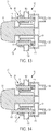
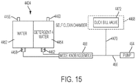
FIG. 15 illustrates a portion of the extractor 420 having acleaning chamber 468 according to another embodiment. The extractor 420 is similar to theextractor 20 described above with reference toFIGS. 1-12 , and similar parts have been given the same reference number plus 400. Only differences between the embodiments are described. - As shown in
FIGS. 15 and16 , thecleaning chamber 468 of the illustrated embodiment includes aduckbill valve 472 instead of thecleaning chamber valve 72 to selectively permit introduction of the cleaning fluid into thecleaning chamber 468. Theduckbill valve 472 includes a first end having an opening, and an intermediate portion that converges toward a second end having a flat gate. Theduckbill valve 472 is disposed within thecleaning chamber 468 in communication with the supply tank 424 via the second fluid flow path 470. The flat gate of theduckbill valve 472 is moveable between a closed or "default" position, in which fluid is inhibited to flow (i.e., prevent backflow from the supply tank 424 to the cleaning chamber 468), and an open position, in which fluid is permitted to flow. - In operation, the hose end 430 is inserted in the
cleaning chamber 468. Suction at the hose end 430 provided by the suction source draws fluid along the fluid flow path 470 through the duckbill valve. As such, the cleaning fluid is permitted to enter the hose end 430. Alternatively or additionally, the cleaning fluid is supplied to thecleaning chamber 468 via thepump 464 of the fluid delivery system. -
FIG. 17 illustrates a portion of the extractor 520 having acleaning chamber 568 according to another embodiment. The extractor 520 is similar to theextractor 20 described above with reference toFIGS. 1-12 , and similar parts have been given the same reference number plus 500. Only differences between the embodiments are described. - As shown in
FIG. 17 , thecleaning chamber 568 of the illustrated embodiment is in communication with the secondfluid flow path 570 and the supply tank 3524 without a valve disposed therebetween. Specifically, the secondfluid flow path 570 is open to air. In this case, thepump 564 does not feed the cleaning fluid to thecleaning chamber 568. Rather, the suction at the hose end 530 provided by the suction source 29 is utilized for drawing the cleaning fluid from thesupply tank 524 to thecleaning chamber 568 when the hose end 530 is disposed in thecleaning chamber 568. Also, gravity may work alone or in combination with the suction source 529 to provide a gravity feed of the cleaning fluid into thecleaning chamber 568. Thepump 564 is a centrifugal pump and is utilized strictly to feed the cleaning fluid along the firstfluid flow path 566 toward the accessory tool 534. Occasionally, air may collect in thecentrifugal pump 564 which, in turn, requires thepump 564 to be primed (i.e., filled totally with water) prior to operating. Leaving the secondfluid flow path 570 open to air enables thepump 564 to be primed with ease. - During operation, the hose end 530 is inserted in the
cleaning chamber 568. Subsequently, the suction at the hose end 530 provided by the suction source 529 draws cleaning fluid from thesupply tank 524 along the secondfluid flow path 570. Cleaning fluid can also be fed along the firstfluid flow path 566 via thecentrifugal pump 564 toward the surface to be cleaned. Air that is entrained during operation of thecentrifugal pump 564 escapes to atmospheric air through the secondfluid flow path 570. In other embodiments, suction of the suction source 529 may work in combination with gravity feed to deliver the cleaning fluid to thecleaning chamber 568. -
FIG. 18 illustrates a portion of an extractor 620 having acleaning chamber 668 according to another embodiment. The extractor 620 is similar to theextractor 20 described above with reference toFIGS. 1-12 , and similar parts have been given the same reference number plus 600. Only differences between the embodiments are described. - As shown in
FIG. 18 , the accessory tool 634 operates as the suction nozzle. As such, thecleaning chamber 668 receives the accessory tool 634 in its entirety. In some embodiments, thecleaning chamber 668 may receive only a portion of the accessory tool 634 (e.g., theintake nozzle 644 and agitator 646), in which case is more suitable if theagitator 646 is a rotary brush that spins in response to a turbine that rotates as air is drawn passed the turbine. Although the accessory tool 634 of the illustrated embodiment is mounted vertically within thecleaning chamber 668, the accessory tool 634 may be mounted horizontally within thecleaning chamber 668 or in any other orientation. In any orientation, theintake nozzle 644 can be positioned at a low point within thecleaning chamber 668 so as to draw out all of the liquid from thecleaning chamber 668. Optionally, at least onespray jet 669 is in communication with second fluid flow path 670 and provided within thecleaning chamber 668 to direct the cleaning fluid toward the accessory tool 634 to clean the accessory tool 634 and/or theagitator 646 of the accessory tool 634. The accessory tool 634 is coupled to thehose end 630 andhose 632, which is further in communication with the suction source 629 and therecovery tank 626. - During operation, the accessory tool 634 is mounted within the
cleaning chamber 668. The cleaning fluid is expelled from the at least onespray jet 669 toward the accessory tool 634 to clean the accessory tool 634 of waste, and the cleaning fluid and waste is temporarily collected within thecleaning chamber 668. Once the cleaning fluid collected in thecleaning chamber 668 reaches a predetermined height such as along an inclined floor of the chamber 668 (indicated by line 671), the cleaning fluid and waste are drawn into theintake nozzle 644 of the accessory tool 634 (indicated by arrows 673). Thus, the accessory tool 634, theintake nozzle 644, and thehose 632 are cleaned simultaneously, while the cleaning fluid and waste are discharged into therecovery tank 626. -
FIG. 19 illustrates a portion of the extractor 720 having acleaning chamber 768 according to an alternative embodiment. The extractor 720 is similar to the extractor 620 described above with reference toFIG. 18 , and similar parts have been given the same reference number plus 100. Only differences between the embodiments are described. - As shown in
FIG. 19 , theaccessory tool 734 is a plurality of accessory tools that are received within thecleaning chamber 768 to clean theaccessory tools 734 of waste. In the illustrated embodiment, the hose end 730 andhose 732 are coupled to thecleaning chamber 768 via adrain reservoir 775, such that thehose 732 does not connect to either of theaccessory tools 734. In an alternative embodiment, theaccessory tools 734 may be connected together and to thehose 732 via a split or T-hose in a similar construction to the embodiment ofFIG. 18 . - During operation, the fluid expelled from the at least
spray jet 769 toward the plurality ofaccessory tools 734 is collected in thecleaning chamber 768. In this case, the cleaning fluid and waste that is collected in thecleaning chamber 768 is drawn out of thecleaning chamber 768 through thedrain reservoir 775. Subsequently, the cleaning fluid and waste flows through thehose 732 and expelled and stored in therecovery tank 726. - Thus, the invention provides, among other things, a self-cleaning system for an extractor cleaning machine.
Claims (15)
- An extractor (20, 220, 320, 420, 520, 620, 720) comprising:a housing (22);a suction source (29, 529, 629) disposed within the housing (22);a suction nozzle (34, 534, 634, 734) in communication with the suction source and movable relative to the housing;a recovery tank (26, 626, 726) carried by the housing, wherein the suction source is in communication with the recovery tank for drawing fluid through the suction nozzle and storing the drawn fluid in the recovery tank; anda cleaning chamber (68, 268, 368, 468, 568, 668, 768) with the housing for receiving at least a portion of the suction nozzle,wherein the cleaning chamber is configured to selectively receive a cleaning fluid along a fluid flow path (70, 470, 570, 670) in communication with the cleaning chamber,wherein the suction source is in communication with the cleaning chamber and configured to draw the cleaning fluid through the fluid flow path (66, 566, 70, 470, 570, 670) to the recovery tank when the portion of the suction nozzle is received in the cleaning chamber.
- The extractor of claim 1, wherein the fluid flow path (70, 470, 570, 670) provides fluid communication between a supply tank (24, 224, 324, 424, 524) and the cleaning chamber (68, 268, 368, 468, 568, 668, 768), and preferably wherein the supply tank is removably coupled to the housing.
- The extractor of claim 2, further comprising a fluid inlet port (386) in fluid communication with the cleaning chamber (368), wherein the cleaning chamber (368) is configured to selectively receive fluid from the supply tank (324), the fluid inlet port (386), or a combination of the supply tank (324) and the fluid inlet port (386).
- The extractor of claim 3, wherein:the fluid inlet port (386) is configured to selectively receive fluid from a container (265); orthe fluid flow path provides (70) fluid from the supply tank (324), the fluid inlet port, or a combination of the supply tank and the fluid inlet port, to the recovery tank (26) when the portion of the suction nozzle (34) is received in the cleaning chamber (368).
- The extractor of claim 4, wherein the suction source (29, 529, 629) is in communication with a hose (32) for drawing the cleaning fluid from the supply tank (24, 224, 324, 424, 524) through the fluid flow path (66, 566, 70, 470, 570, 670) and a hose to the recovery tank (26, 626, 726) when the portion of the suction nozzle (34, 534, 634, 734) is received in the cleaning chamber (68, 268, 368, 468, 568, 668, 768).
- The extractor of claim 2, wherein the fluid flow path (66, 566, 70, 470, 570, 670) provides fluid from the supply tank (24, 224, 324, 424, 524) to the recovery tank (26, 626, 726) when the portion of the suction nozzle (34, 534, 634, 734) is received in the cleaning chamber (68, 268, 368, 468, 568, 668, 768), preferably further comprising a hose (632) between the suction source (629) and the suction nozzle (634)..
- The extractor of claim 1, further comprising a fluid inlet port (386) in fluid communication with the fluid flow path (70), preferably wherein the fluid flow path provides fluid communication from the fluid inlet port to the recovery tank (26) when the portion of the suction nozzle is received in the cleaning chamber (368).
- The extractor of claim 1, further comprising:
a hose (32) between the suction source (29) and the suction nozzle (34); or
a supply tank (24, 224, 324, 424, 524) including a first fluid tank (52) for storing a first fluid, and a second fluid tank (54) for storing a second fluid; or
a user-selectable mode valve assembly (88), the mode valve assembly including a valve (92) selectively switching between a first mode connecting the first fluid tank (52) to the fluid flow path and a second mode connecting the second fluid tank (54) to the fluid flow path (66, 566). - The extractor of claim 8, wherein the mode valve assembly (88) includes
a first inlet port (102) in communication with the first fluid tank (52),
a second inlet port (106) in communication with the second fluid tank (54),
the valve (92) connecting the first fluid tank (52) and the second fluid tank (54) with an outlet port (104, 108) in communication with the fluid flow path (66, 566); or
wherein the mode valve assembly includes a third mode connecting the first fluid tank and second fluid tank to the fluid flow path; or
further comprising a fluid delivery system in communication with the fluid flow path that selectively delivers fluid to a surface to be cleaned. - The extractor of claim 9, wherein the fluid delivery system is at least partially supported by the suction nozzle (34, 534, 634, 734), preferably further comprising a fluid delivery system in communication with the fluid flow path (66, 566) that selectively delivers fluid to a surface to be cleaned.
- The extractor of claim 10, wherein the fluid delivery system is at least partially supported by the suction nozzle (34, 534, 634, 734).
- The extractor of claim 1, wherein the cleaning chamber (68, 268, 368, 668, 768) includes a valve (72, 472) configured to selectively permit introduction of the cleaning fluid into the cleaning chamber, preferably wherein the valve includes a plunger (76) actuatable between a first position to inhibit the cleaning fluid from entering the cleaning chamber (68, 268, 368, 668, 768), and a second position to permit the cleaning fluid to enter the cleaning chamber.
- The extractor of claim 12, wherein the plunger (76) is forced by a spring (80) toward the first position, and the suction nozzle (34, 634, 734) moves the plunger toward the second position when the portion of the suction nozzle is inserted into the cleaning chamber (68, 268, 368, 668, 768).
- The extractor of claim 1, wherein:
the suction nozzle (634, 734) is a cleaning tool, and the cleaning chamber (668, 768) receives the cleaning tool, wherein the cleaning chamber includes at least one spray (669, 769) for spraying fluid toward the cleaning tool within the cleaning chamber; orthe fluid flow path (66) is in communication with a pump (64, 464) providing fluid to the cleaning chamber; ora controller deactivates the suction source (29, 529, 629) in response to one or more inputs selected from a group consisting of a user actuated switch (38), amount of fluid in the supply tank (24, 224, 324, 424, 524), amount of fluid in the recovery tank (36, 626, 726), time, and air pressure in the system. - The extractor of claim 1, further comprising a plurality of cleaning tools (734), wherein the cleaning chamber (768) receives the plurality of cleaning tools and the portion of the suction nozzle (724).
Applications Claiming Priority (2)
| Application Number | Priority Date | Filing Date | Title |
|---|---|---|---|
| US201562253920P | 2015-11-11 | 2015-11-11 | |
| PCT/US2016/052687 WO2017083009A1 (en) | 2015-11-11 | 2016-09-20 | Extractor cleaning machine |
Publications (2)
| Publication Number | Publication Date |
|---|---|
| EP3373790A1 EP3373790A1 (en) | 2018-09-19 |
| EP3373790B1 true EP3373790B1 (en) | 2019-06-12 |
Family
ID=57113725
Family Applications (1)
| Application Number | Title | Priority Date | Filing Date |
|---|---|---|---|
| EP16778560.9A Active EP3373790B1 (en) | 2015-11-11 | 2016-09-20 | Extractor cleaning machine |
Country Status (6)
| Country | Link |
|---|---|
| US (3) | US20170127900A1 (en) |
| EP (1) | EP3373790B1 (en) |
| KR (1) | KR102594933B1 (en) |
| CN (1) | CN108348125B (en) |
| AU (1) | AU2016329041B2 (en) |
| WO (1) | WO2017083009A1 (en) |
Cited By (1)
| Publication number | Priority date | Publication date | Assignee | Title |
|---|---|---|---|---|
| US11172799B2 (en) | 2018-12-28 | 2021-11-16 | Techtronic Floor Care Technology Limited | Portable extractor |
Families Citing this family (27)
| Publication number | Priority date | Publication date | Assignee | Title |
|---|---|---|---|---|
| AU2017248437B2 (en) * | 2016-10-25 | 2023-08-03 | Bissell Inc. | Pet bathing tool and system |
| US10674881B2 (en) * | 2017-09-19 | 2020-06-09 | Rug Doctor, LLC | Liquid extraction apparatus and method |
| USD873512S1 (en) * | 2017-09-19 | 2020-01-21 | Rug Doctor, LLC | Surface cleaning system |
| AU2018101447A4 (en) | 2017-10-06 | 2018-11-08 | Bissell Inc. | Self-cleaning features for extraction cleaners |
| PT3656270T (en) | 2018-03-05 | 2021-06-24 | Bissell Inc | Extraction cleaner |
| EP3932280B1 (en) * | 2018-09-21 | 2024-12-18 | Techtronic Floor Care Technology Limited | Portable extractor |
| WO2020061422A1 (en) | 2018-09-21 | 2020-03-26 | Tti (Macao Commercial Offshore) Limited | Portable extractor |
| CN109528103B (en) * | 2019-01-22 | 2023-09-15 | 苏州锐科兰电器有限公司 | Floor mopping machine |
| EP3782463B1 (en) * | 2019-08-22 | 2023-02-22 | Bissell Inc. | Portable pet grooming system |
| WO2021141778A1 (en) | 2020-01-06 | 2021-07-15 | Techtronic Cordless Gp | Cleaning system with full recovery tank shutoff |
| CN113367607A (en) * | 2020-03-10 | 2021-09-10 | 苏州宝时得电动工具有限公司 | Water absorption assembly of dust collector and dust collector |
| USD979163S1 (en) * | 2020-08-20 | 2023-02-21 | Techtronic Floor Care Technology Limited | Floor cleaner |
| GB2615717B (en) * | 2020-12-01 | 2025-01-29 | Techtronic Floor Care Tech Ltd | Surface cleaner |
| EP4059406B1 (en) | 2021-03-17 | 2026-02-25 | Dupray Ventures Inc. | Spot cleaner apparatus |
| AU2022291569A1 (en) | 2022-01-10 | 2023-07-27 | Bissell Inc. | Surface cleaning apparatus with steam |
| CN114468839A (en) * | 2022-01-29 | 2022-05-13 | 苏州爱普电器有限公司 | Suction tube for a surface cleaning device |
| US11986139B2 (en) | 2022-02-02 | 2024-05-21 | Bissell Inc. | Extraction cleaner with steam |
| USD1017156S1 (en) | 2022-05-09 | 2024-03-05 | Dupray Ventures Inc. | Cleaner |
| EP4520244A3 (en) * | 2022-07-06 | 2025-06-18 | Bissell Inc. | Extraction cleaner |
| US20240032757A1 (en) * | 2022-07-26 | 2024-02-01 | Bissell Inc. | Extraction cleaner systems, methods, and devices with disposable absorbent pads in recovery pathway |
| CN219000180U (en) * | 2022-12-29 | 2023-05-12 | 溢锋智能科技(深圳)有限公司 | Fabric and pet cleaning machine |
| CN120731037A (en) | 2023-01-20 | 2025-09-30 | 尚科宁家运营有限公司 | Extraction cleaner |
| USD1096025S1 (en) * | 2023-04-11 | 2025-09-30 | Suzhou Grand Electric Co., Ltd | Vacuum cleaner |
| USD1085594S1 (en) * | 2023-06-05 | 2025-07-22 | Bissell Homecare, Inc. | Portable cleaning appliance |
| US20250017436A1 (en) * | 2023-07-14 | 2025-01-16 | Ron Jones | Waste Suctioning And Surface Disinfecting Device And Method Of Use |
| USD1056376S1 (en) * | 2024-04-30 | 2024-12-31 | Ningbo Huayi Electronic Appliance Technology Co. , Ltd. | Portable carpet cleaner |
| EP4687606A1 (en) * | 2024-06-04 | 2026-02-11 | SharkNinja Operating LLC | Cleaning apparatus |
Citations (6)
| Publication number | Priority date | Publication date | Assignee | Title |
|---|---|---|---|---|
| US20050015916A1 (en) | 2003-06-06 | 2005-01-27 | Lawrence Orubor | Wet-dry vacuum cleaning device |
| US20090070953A1 (en) | 2007-04-04 | 2009-03-19 | Orubor Integrated Technology Inc. | Self-evacuating vacuum device |
| US20120192376A1 (en) | 2011-02-01 | 2012-08-02 | Lawrence Orubor | Apparatus For Clearing Waste From A Surface |
| US20130269144A1 (en) | 2012-04-11 | 2013-10-17 | Lawrence Orubor | Apparatus for cleaning waste from a surface |
| EP2684501A1 (en) | 2012-06-01 | 2014-01-15 | Bissell Homecare, Inc. | Surface cleaning apparatus |
| WO2015000505A1 (en) | 2013-07-02 | 2015-01-08 | Alfred Kärcher Gmbh & Co. Kg | Suction apparatus and method for operating a suction apparatus |
Family Cites Families (23)
| Publication number | Priority date | Publication date | Assignee | Title |
|---|---|---|---|---|
| US2475815A (en) * | 1946-03-29 | 1949-07-12 | Aget Mfg Company | Vacuum cleaning device |
| US4974618A (en) * | 1983-08-31 | 1990-12-04 | Duraclean International, Inc. | Apparatus and method for fabric cleaning with foam |
| US5870798A (en) * | 1996-05-03 | 1999-02-16 | The Hoover Company | Compact carpet and upholstery extractor |
| US6041470A (en) | 1998-10-30 | 2000-03-28 | Branham; James C. | Carpet brush cleaning device |
| US6453507B1 (en) | 1999-03-16 | 2002-09-24 | Gene Wilson Gilbert | Self contained, self-cleaning, wet/dry vacuum machine |
| SE517347C2 (en) * | 1999-12-03 | 2002-05-28 | Electrolux Ab | Device for a vacuum cleaner |
| IT1315066B1 (en) * | 2000-12-15 | 2003-01-27 | Douss Line S R L | APPARATUS FOR CLEANING Brooms, BRUSHES, SIMILAR BRUSHES |
| US7073226B1 (en) * | 2001-11-30 | 2006-07-11 | Bissell Homecare, Inc. | Portable extraction cleaner |
| US6802104B1 (en) * | 2002-04-02 | 2004-10-12 | Katherine B. Redd | Vacuum hose attachment |
| US7150285B2 (en) * | 2003-01-21 | 2006-12-19 | Matsushita Electric Works, Ltd. | Cleaning device for a hair removing apparatus |
| US7104474B2 (en) * | 2004-01-02 | 2006-09-12 | Vita-Mix Corporation | Container cleaning device |
| US7475448B2 (en) * | 2004-07-02 | 2009-01-13 | Euro-Pro Operating, Llp | Liquid dispensing device and steam cleaner containing same |
| US7703170B2 (en) * | 2004-12-29 | 2010-04-27 | Lawrence Orubor | Self-cleaning wet dry vacuum cleaning device |
| US7854033B1 (en) * | 2007-12-21 | 2010-12-21 | Kinder Jack G | Apparatus and method for cleaning a mop |
| US8549697B1 (en) * | 2008-05-29 | 2013-10-08 | Bissell Homecare, Inc. | Unattended spot cleaning with surface sanitization |
| US8635738B2 (en) | 2009-12-22 | 2014-01-28 | Ab Electrolux | Dusting system |
| AU2012201110B2 (en) * | 2011-03-02 | 2014-10-16 | Bissell Inc. | Floor cleaner with stowable handle |
| CN202235158U (en) | 2011-09-28 | 2012-05-30 | 天津市职业大学 | Dust collector capable of preventing secondary pollution |
| WO2013071042A1 (en) | 2011-11-10 | 2013-05-16 | Stryker Corporation | Cleaning system and equipment therefor |
| KR101240129B1 (en) * | 2011-11-30 | 2013-03-11 | 육성훈 | Automatic washing machine for mop |
| CN102688002B (en) * | 2012-05-11 | 2015-01-21 | 广西大学 | Multifunctional integrated household floor cleaner robot |
| US9717386B2 (en) * | 2014-02-28 | 2017-08-01 | Rug Doctor, LLC | Liquid extraction cleaning device |
| CN204467955U (en) * | 2015-03-14 | 2015-07-15 | 鲁刚 | Can cleaning type cleaning vehicle |
-
2016
- 2016-09-20 EP EP16778560.9A patent/EP3373790B1/en active Active
- 2016-09-20 CN CN201680065912.4A patent/CN108348125B/en active Active
- 2016-09-20 AU AU2016329041A patent/AU2016329041B2/en active Active
- 2016-09-20 WO PCT/US2016/052687 patent/WO2017083009A1/en not_active Ceased
- 2016-09-20 KR KR1020187015988A patent/KR102594933B1/en active Active
- 2016-09-20 US US15/270,897 patent/US20170127900A1/en not_active Abandoned
-
2022
- 2022-01-14 US US17/576,586 patent/US12239266B2/en active Active
-
2025
- 2025-01-17 US US19/027,386 patent/US20250160594A1/en active Pending
Patent Citations (6)
| Publication number | Priority date | Publication date | Assignee | Title |
|---|---|---|---|---|
| US20050015916A1 (en) | 2003-06-06 | 2005-01-27 | Lawrence Orubor | Wet-dry vacuum cleaning device |
| US20090070953A1 (en) | 2007-04-04 | 2009-03-19 | Orubor Integrated Technology Inc. | Self-evacuating vacuum device |
| US20120192376A1 (en) | 2011-02-01 | 2012-08-02 | Lawrence Orubor | Apparatus For Clearing Waste From A Surface |
| US20130269144A1 (en) | 2012-04-11 | 2013-10-17 | Lawrence Orubor | Apparatus for cleaning waste from a surface |
| EP2684501A1 (en) | 2012-06-01 | 2014-01-15 | Bissell Homecare, Inc. | Surface cleaning apparatus |
| WO2015000505A1 (en) | 2013-07-02 | 2015-01-08 | Alfred Kärcher Gmbh & Co. Kg | Suction apparatus and method for operating a suction apparatus |
Cited By (2)
| Publication number | Priority date | Publication date | Assignee | Title |
|---|---|---|---|---|
| US11172799B2 (en) | 2018-12-28 | 2021-11-16 | Techtronic Floor Care Technology Limited | Portable extractor |
| US11844483B2 (en) | 2018-12-28 | 2023-12-19 | Techtronic Floor Care Technology Limited | Portable extractor |
Also Published As
| Publication number | Publication date |
|---|---|
| WO2017083009A1 (en) | 2017-05-18 |
| KR20180081110A (en) | 2018-07-13 |
| US20220133113A1 (en) | 2022-05-05 |
| CN108348125B (en) | 2022-07-19 |
| KR102594933B1 (en) | 2023-10-27 |
| CN108348125A (en) | 2018-07-31 |
| US20250160594A1 (en) | 2025-05-22 |
| US12239266B2 (en) | 2025-03-04 |
| AU2016329041B2 (en) | 2018-11-15 |
| EP3373790A1 (en) | 2018-09-19 |
| AU2016329041A1 (en) | 2017-05-25 |
| US20170127900A1 (en) | 2017-05-11 |
Similar Documents
| Publication | Publication Date | Title |
|---|---|---|
| US12239266B2 (en) | Extractor cleaning machine | |
| US12349846B2 (en) | Self-cleaning features for extraction cleaners | |
| US11382481B2 (en) | Extraction cleaner | |
| US8887347B2 (en) | Conversion mechanism for switching extractor cleaning machine from floor cleaning to hose cleaning | |
| EP3116370B1 (en) | Air duct for an extractor cleaning machine | |
| CN117582145A (en) | Wand assemblies, self-cleaning hose systems and suction cleaners | |
| WO2016025239A1 (en) | Extractor cleaning machine | |
| KR100654818B1 (en) | Steam vacuum cleaner |
Legal Events
| Date | Code | Title | Description |
|---|---|---|---|
| STAA | Information on the status of an ep patent application or granted ep patent |
Free format text: STATUS: THE INTERNATIONAL PUBLICATION HAS BEEN MADE |
|
| PUAI | Public reference made under article 153(3) epc to a published international application that has entered the european phase |
Free format text: ORIGINAL CODE: 0009012 |
|
| STAA | Information on the status of an ep patent application or granted ep patent |
Free format text: STATUS: REQUEST FOR EXAMINATION WAS MADE |
|
| 17P | Request for examination filed |
Effective date: 20180320 |
|
| AK | Designated contracting states |
Kind code of ref document: A1 Designated state(s): AL AT BE BG CH CY CZ DE DK EE ES FI FR GB GR HR HU IE IS IT LI LT LU LV MC MK MT NL NO PL PT RO RS SE SI SK SM TR |
|
| AX | Request for extension of the european patent |
Extension state: BA ME |
|
| DAV | Request for validation of the european patent (deleted) | ||
| DAX | Request for extension of the european patent (deleted) | ||
| GRAP | Despatch of communication of intention to grant a patent |
Free format text: ORIGINAL CODE: EPIDOSNIGR1 |
|
| STAA | Information on the status of an ep patent application or granted ep patent |
Free format text: STATUS: GRANT OF PATENT IS INTENDED |
|
| INTG | Intention to grant announced |
Effective date: 20190312 |
|
| GRAS | Grant fee paid |
Free format text: ORIGINAL CODE: EPIDOSNIGR3 |
|
| GRAA | (expected) grant |
Free format text: ORIGINAL CODE: 0009210 |
|
| STAA | Information on the status of an ep patent application or granted ep patent |
Free format text: STATUS: THE PATENT HAS BEEN GRANTED |
|
| AK | Designated contracting states |
Kind code of ref document: B1 Designated state(s): AL AT BE BG CH CY CZ DE DK EE ES FI FR GB GR HR HU IE IS IT LI LT LU LV MC MK MT NL NO PL PT RO RS SE SI SK SM TR |
|
| REG | Reference to a national code |
Ref country code: GB Ref legal event code: FG4D |
|
| REG | Reference to a national code |
Ref country code: CH Ref legal event code: EP |
|
| REG | Reference to a national code |
Ref country code: AT Ref legal event code: REF Ref document number: 1141480 Country of ref document: AT Kind code of ref document: T Effective date: 20190615 |
|
| REG | Reference to a national code |
Ref country code: DE Ref legal event code: R096 Ref document number: 602016015316 Country of ref document: DE |
|
| REG | Reference to a national code |
Ref country code: IE Ref legal event code: FG4D |
|
| REG | Reference to a national code |
Ref country code: NL Ref legal event code: MP Effective date: 20190612 |
|
| REG | Reference to a national code |
Ref country code: LT Ref legal event code: MG4D |
|
| PG25 | Lapsed in a contracting state [announced via postgrant information from national office to epo] |
Ref country code: SE Free format text: LAPSE BECAUSE OF FAILURE TO SUBMIT A TRANSLATION OF THE DESCRIPTION OR TO PAY THE FEE WITHIN THE PRESCRIBED TIME-LIMIT Effective date: 20190612 Ref country code: HR Free format text: LAPSE BECAUSE OF FAILURE TO SUBMIT A TRANSLATION OF THE DESCRIPTION OR TO PAY THE FEE WITHIN THE PRESCRIBED TIME-LIMIT Effective date: 20190612 Ref country code: LT Free format text: LAPSE BECAUSE OF FAILURE TO SUBMIT A TRANSLATION OF THE DESCRIPTION OR TO PAY THE FEE WITHIN THE PRESCRIBED TIME-LIMIT Effective date: 20190612 Ref country code: AL Free format text: LAPSE BECAUSE OF FAILURE TO SUBMIT A TRANSLATION OF THE DESCRIPTION OR TO PAY THE FEE WITHIN THE PRESCRIBED TIME-LIMIT Effective date: 20190612 Ref country code: NO Free format text: LAPSE BECAUSE OF FAILURE TO SUBMIT A TRANSLATION OF THE DESCRIPTION OR TO PAY THE FEE WITHIN THE PRESCRIBED TIME-LIMIT Effective date: 20190912 Ref country code: FI Free format text: LAPSE BECAUSE OF FAILURE TO SUBMIT A TRANSLATION OF THE DESCRIPTION OR TO PAY THE FEE WITHIN THE PRESCRIBED TIME-LIMIT Effective date: 20190612 |
|
| PG25 | Lapsed in a contracting state [announced via postgrant information from national office to epo] |
Ref country code: BG Free format text: LAPSE BECAUSE OF FAILURE TO SUBMIT A TRANSLATION OF THE DESCRIPTION OR TO PAY THE FEE WITHIN THE PRESCRIBED TIME-LIMIT Effective date: 20190912 Ref country code: LV Free format text: LAPSE BECAUSE OF FAILURE TO SUBMIT A TRANSLATION OF THE DESCRIPTION OR TO PAY THE FEE WITHIN THE PRESCRIBED TIME-LIMIT Effective date: 20190612 Ref country code: GR Free format text: LAPSE BECAUSE OF FAILURE TO SUBMIT A TRANSLATION OF THE DESCRIPTION OR TO PAY THE FEE WITHIN THE PRESCRIBED TIME-LIMIT Effective date: 20190913 Ref country code: RS Free format text: LAPSE BECAUSE OF FAILURE TO SUBMIT A TRANSLATION OF THE DESCRIPTION OR TO PAY THE FEE WITHIN THE PRESCRIBED TIME-LIMIT Effective date: 20190612 |
|
| REG | Reference to a national code |
Ref country code: AT Ref legal event code: MK05 Ref document number: 1141480 Country of ref document: AT Kind code of ref document: T Effective date: 20190612 |
|
| PG25 | Lapsed in a contracting state [announced via postgrant information from national office to epo] |
Ref country code: NL Free format text: LAPSE BECAUSE OF FAILURE TO SUBMIT A TRANSLATION OF THE DESCRIPTION OR TO PAY THE FEE WITHIN THE PRESCRIBED TIME-LIMIT Effective date: 20190612 Ref country code: PT Free format text: LAPSE BECAUSE OF FAILURE TO SUBMIT A TRANSLATION OF THE DESCRIPTION OR TO PAY THE FEE WITHIN THE PRESCRIBED TIME-LIMIT Effective date: 20191014 Ref country code: CZ Free format text: LAPSE BECAUSE OF FAILURE TO SUBMIT A TRANSLATION OF THE DESCRIPTION OR TO PAY THE FEE WITHIN THE PRESCRIBED TIME-LIMIT Effective date: 20190612 Ref country code: RO Free format text: LAPSE BECAUSE OF FAILURE TO SUBMIT A TRANSLATION OF THE DESCRIPTION OR TO PAY THE FEE WITHIN THE PRESCRIBED TIME-LIMIT Effective date: 20190612 Ref country code: SK Free format text: LAPSE BECAUSE OF FAILURE TO SUBMIT A TRANSLATION OF THE DESCRIPTION OR TO PAY THE FEE WITHIN THE PRESCRIBED TIME-LIMIT Effective date: 20190612 Ref country code: EE Free format text: LAPSE BECAUSE OF FAILURE TO SUBMIT A TRANSLATION OF THE DESCRIPTION OR TO PAY THE FEE WITHIN THE PRESCRIBED TIME-LIMIT Effective date: 20190612 Ref country code: AT Free format text: LAPSE BECAUSE OF FAILURE TO SUBMIT A TRANSLATION OF THE DESCRIPTION OR TO PAY THE FEE WITHIN THE PRESCRIBED TIME-LIMIT Effective date: 20190612 |
|
| PG25 | Lapsed in a contracting state [announced via postgrant information from national office to epo] |
Ref country code: IS Free format text: LAPSE BECAUSE OF FAILURE TO SUBMIT A TRANSLATION OF THE DESCRIPTION OR TO PAY THE FEE WITHIN THE PRESCRIBED TIME-LIMIT Effective date: 20191012 Ref country code: SM Free format text: LAPSE BECAUSE OF FAILURE TO SUBMIT A TRANSLATION OF THE DESCRIPTION OR TO PAY THE FEE WITHIN THE PRESCRIBED TIME-LIMIT Effective date: 20190612 Ref country code: ES Free format text: LAPSE BECAUSE OF FAILURE TO SUBMIT A TRANSLATION OF THE DESCRIPTION OR TO PAY THE FEE WITHIN THE PRESCRIBED TIME-LIMIT Effective date: 20190612 Ref country code: IT Free format text: LAPSE BECAUSE OF FAILURE TO SUBMIT A TRANSLATION OF THE DESCRIPTION OR TO PAY THE FEE WITHIN THE PRESCRIBED TIME-LIMIT Effective date: 20190612 |
|
| REG | Reference to a national code |
Ref country code: DE Ref legal event code: R026 Ref document number: 602016015316 Country of ref document: DE |
|
| PLBI | Opposition filed |
Free format text: ORIGINAL CODE: 0009260 |
|
| PLAX | Notice of opposition and request to file observation + time limit sent |
Free format text: ORIGINAL CODE: EPIDOSNOBS2 |
|
| PG25 | Lapsed in a contracting state [announced via postgrant information from national office to epo] |
Ref country code: TR Free format text: LAPSE BECAUSE OF FAILURE TO SUBMIT A TRANSLATION OF THE DESCRIPTION OR TO PAY THE FEE WITHIN THE PRESCRIBED TIME-LIMIT Effective date: 20190612 |
|
| 26 | Opposition filed |
Opponent name: STANLEY BLACK & DECKER, INC. Effective date: 20200311 |
|
| PG25 | Lapsed in a contracting state [announced via postgrant information from national office to epo] |
Ref country code: DK Free format text: LAPSE BECAUSE OF FAILURE TO SUBMIT A TRANSLATION OF THE DESCRIPTION OR TO PAY THE FEE WITHIN THE PRESCRIBED TIME-LIMIT Effective date: 20190612 Ref country code: PL Free format text: LAPSE BECAUSE OF FAILURE TO SUBMIT A TRANSLATION OF THE DESCRIPTION OR TO PAY THE FEE WITHIN THE PRESCRIBED TIME-LIMIT Effective date: 20190612 |
|
| PG25 | Lapsed in a contracting state [announced via postgrant information from national office to epo] |
Ref country code: IS Free format text: LAPSE BECAUSE OF FAILURE TO SUBMIT A TRANSLATION OF THE DESCRIPTION OR TO PAY THE FEE WITHIN THE PRESCRIBED TIME-LIMIT Effective date: 20200224 Ref country code: MC Free format text: LAPSE BECAUSE OF FAILURE TO SUBMIT A TRANSLATION OF THE DESCRIPTION OR TO PAY THE FEE WITHIN THE PRESCRIBED TIME-LIMIT Effective date: 20190612 |
|
| REG | Reference to a national code |
Ref country code: CH Ref legal event code: PL |
|
| PG2D | Information on lapse in contracting state deleted |
Ref country code: IS |
|
| PG25 | Lapsed in a contracting state [announced via postgrant information from national office to epo] |
Ref country code: CH Free format text: LAPSE BECAUSE OF NON-PAYMENT OF DUE FEES Effective date: 20190930 Ref country code: LU Free format text: LAPSE BECAUSE OF NON-PAYMENT OF DUE FEES Effective date: 20190920 Ref country code: IE Free format text: LAPSE BECAUSE OF NON-PAYMENT OF DUE FEES Effective date: 20190920 Ref country code: LI Free format text: LAPSE BECAUSE OF NON-PAYMENT OF DUE FEES Effective date: 20190930 |
|
| REG | Reference to a national code |
Ref country code: BE Ref legal event code: MM Effective date: 20190930 |
|
| PLBB | Reply of patent proprietor to notice(s) of opposition received |
Free format text: ORIGINAL CODE: EPIDOSNOBS3 |
|
| PG25 | Lapsed in a contracting state [announced via postgrant information from national office to epo] |
Ref country code: BE Free format text: LAPSE BECAUSE OF NON-PAYMENT OF DUE FEES Effective date: 20190930 |
|
| RAP2 | Party data changed (patent owner data changed or rights of a patent transferred) |
Owner name: TTI (MACAO COMMERCIAL OFFSHORE) LIMITED |
|
| PG25 | Lapsed in a contracting state [announced via postgrant information from national office to epo] |
Ref country code: CY Free format text: LAPSE BECAUSE OF FAILURE TO SUBMIT A TRANSLATION OF THE DESCRIPTION OR TO PAY THE FEE WITHIN THE PRESCRIBED TIME-LIMIT Effective date: 20190612 |
|
| PG25 | Lapsed in a contracting state [announced via postgrant information from national office to epo] |
Ref country code: MT Free format text: LAPSE BECAUSE OF FAILURE TO SUBMIT A TRANSLATION OF THE DESCRIPTION OR TO PAY THE FEE WITHIN THE PRESCRIBED TIME-LIMIT Effective date: 20190612 Ref country code: HU Free format text: LAPSE BECAUSE OF FAILURE TO SUBMIT A TRANSLATION OF THE DESCRIPTION OR TO PAY THE FEE WITHIN THE PRESCRIBED TIME-LIMIT; INVALID AB INITIO Effective date: 20160920 |
|
| PG25 | Lapsed in a contracting state [announced via postgrant information from national office to epo] |
Ref country code: SI Free format text: LAPSE BECAUSE OF FAILURE TO SUBMIT A TRANSLATION OF THE DESCRIPTION OR TO PAY THE FEE WITHIN THE PRESCRIBED TIME-LIMIT Effective date: 20190612 |
|
| REG | Reference to a national code |
Ref country code: DE Ref legal event code: R100 Ref document number: 602016015316 Country of ref document: DE |
|
| RAP2 | Party data changed (patent owner data changed or rights of a patent transferred) |
Owner name: TECHTRONIC FLOOR CARE TECHNOLOGY LIMITED |
|
| PLCK | Communication despatched that opposition was rejected |
Free format text: ORIGINAL CODE: EPIDOSNREJ1 |
|
| PLBN | Opposition rejected |
Free format text: ORIGINAL CODE: 0009273 |
|
| STAA | Information on the status of an ep patent application or granted ep patent |
Free format text: STATUS: OPPOSITION REJECTED |
|
| 27O | Opposition rejected |
Effective date: 20211029 |
|
| PG25 | Lapsed in a contracting state [announced via postgrant information from national office to epo] |
Ref country code: MK Free format text: LAPSE BECAUSE OF FAILURE TO SUBMIT A TRANSLATION OF THE DESCRIPTION OR TO PAY THE FEE WITHIN THE PRESCRIBED TIME-LIMIT Effective date: 20190612 |
|
| PGFP | Annual fee paid to national office [announced via postgrant information from national office to epo] |
Ref country code: DE Payment date: 20220928 Year of fee payment: 7 |
|
| PGFP | Annual fee paid to national office [announced via postgrant information from national office to epo] |
Ref country code: FR Payment date: 20220926 Year of fee payment: 7 |
|
| REG | Reference to a national code |
Ref country code: DE Ref legal event code: R119 Ref document number: 602016015316 Country of ref document: DE |
|
| PG25 | Lapsed in a contracting state [announced via postgrant information from national office to epo] |
Ref country code: FR Free format text: LAPSE BECAUSE OF NON-PAYMENT OF DUE FEES Effective date: 20230930 Ref country code: DE Free format text: LAPSE BECAUSE OF NON-PAYMENT OF DUE FEES Effective date: 20240403 |
|
| PGFP | Annual fee paid to national office [announced via postgrant information from national office to epo] |
Ref country code: GB Payment date: 20250929 Year of fee payment: 10 |