EP3373762B1 - Footwear sole structure - Google Patents
Footwear sole structure Download PDFInfo
- Publication number
- EP3373762B1 EP3373762B1 EP16801670.7A EP16801670A EP3373762B1 EP 3373762 B1 EP3373762 B1 EP 3373762B1 EP 16801670 A EP16801670 A EP 16801670A EP 3373762 B1 EP3373762 B1 EP 3373762B1
- Authority
- EP
- European Patent Office
- Prior art keywords
- round shell
- shell components
- sole
- round
- components
- Prior art date
- Legal status (The legal status is an assumption and is not a legal conclusion. Google has not performed a legal analysis and makes no representation as to the accuracy of the status listed.)
- Active
Links
- 210000003041 ligament Anatomy 0.000 claims description 57
- 239000011800 void material Substances 0.000 claims description 23
- 210000004744 fore-foot Anatomy 0.000 claims description 20
- 210000000452 mid-foot Anatomy 0.000 claims description 19
- 239000000463 material Substances 0.000 claims description 18
- 239000012530 fluid Substances 0.000 claims description 3
- 239000013078 crystal Substances 0.000 claims description 2
- 239000000945 filler Substances 0.000 description 16
- 210000000474 heel Anatomy 0.000 description 14
- 210000002683 foot Anatomy 0.000 description 11
- 238000011038 discontinuous diafiltration by volume reduction Methods 0.000 description 8
- 230000008859 change Effects 0.000 description 5
- 239000010410 layer Substances 0.000 description 5
- 238000000034 method Methods 0.000 description 5
- 230000004043 responsiveness Effects 0.000 description 5
- 239000004433 Thermoplastic polyurethane Substances 0.000 description 4
- 229920002803 thermoplastic polyurethane Polymers 0.000 description 4
- 239000005038 ethylene vinyl acetate Substances 0.000 description 3
- 230000009466 transformation Effects 0.000 description 3
- 230000009471 action Effects 0.000 description 2
- 230000000386 athletic effect Effects 0.000 description 2
- DQXBYHZEEUGOBF-UHFFFAOYSA-N but-3-enoic acid;ethene Chemical compound C=C.OC(=O)CC=C DQXBYHZEEUGOBF-UHFFFAOYSA-N 0.000 description 2
- 229920001971 elastomer Polymers 0.000 description 2
- 229920001200 poly(ethylene-vinyl acetate) Polymers 0.000 description 2
- 229920002614 Polyether block amide Polymers 0.000 description 1
- 239000000654 additive Substances 0.000 description 1
- 230000000996 additive effect Effects 0.000 description 1
- 210000003423 ankle Anatomy 0.000 description 1
- 210000000459 calcaneus Anatomy 0.000 description 1
- 230000006835 compression Effects 0.000 description 1
- 238000007906 compression Methods 0.000 description 1
- 230000008602 contraction Effects 0.000 description 1
- 230000001419 dependent effect Effects 0.000 description 1
- 230000000694 effects Effects 0.000 description 1
- 239000000806 elastomer Substances 0.000 description 1
- 239000006260 foam Substances 0.000 description 1
- 238000002347 injection Methods 0.000 description 1
- 239000007924 injection Substances 0.000 description 1
- 238000002955 isolation Methods 0.000 description 1
- 230000009191 jumping Effects 0.000 description 1
- 239000007788 liquid Substances 0.000 description 1
- 238000004519 manufacturing process Methods 0.000 description 1
- 210000001872 metatarsal bone Anatomy 0.000 description 1
- 230000000750 progressive effect Effects 0.000 description 1
- 230000001681 protective effect Effects 0.000 description 1
- 230000003014 reinforcing effect Effects 0.000 description 1
- 230000004044 response Effects 0.000 description 1
- 239000002356 single layer Substances 0.000 description 1
- -1 spring Substances 0.000 description 1
- 230000009897 systematic effect Effects 0.000 description 1
- 229920002725 thermoplastic elastomer Polymers 0.000 description 1
- 210000003371 toe Anatomy 0.000 description 1
- 230000007704 transition Effects 0.000 description 1
Images


Classifications
-
- A—HUMAN NECESSITIES
- A43—FOOTWEAR
- A43B—CHARACTERISTIC FEATURES OF FOOTWEAR; PARTS OF FOOTWEAR
- A43B13/00—Soles; Sole-and-heel integral units
- A43B13/02—Soles; Sole-and-heel integral units characterised by the material
- A43B13/12—Soles with several layers of different materials
- A43B13/125—Soles with several layers of different materials characterised by the midsole or middle layer
-
- A—HUMAN NECESSITIES
- A43—FOOTWEAR
- A43B—CHARACTERISTIC FEATURES OF FOOTWEAR; PARTS OF FOOTWEAR
- A43B13/00—Soles; Sole-and-heel integral units
- A43B13/14—Soles; Sole-and-heel integral units characterised by the constructive form
- A43B13/18—Resilient soles
- A43B13/181—Resiliency achieved by the structure of the sole
- A43B13/186—Differential cushioning region, e.g. cushioning located under the ball of the foot
-
- A—HUMAN NECESSITIES
- A43—FOOTWEAR
- A43B—CHARACTERISTIC FEATURES OF FOOTWEAR; PARTS OF FOOTWEAR
- A43B13/00—Soles; Sole-and-heel integral units
- A43B13/14—Soles; Sole-and-heel integral units characterised by the constructive form
- A43B13/18—Resilient soles
- A43B13/187—Resiliency achieved by the features of the material, e.g. foam, non liquid materials
-
- A—HUMAN NECESSITIES
- A43—FOOTWEAR
- A43B—CHARACTERISTIC FEATURES OF FOOTWEAR; PARTS OF FOOTWEAR
- A43B13/00—Soles; Sole-and-heel integral units
- A43B13/14—Soles; Sole-and-heel integral units characterised by the constructive form
- A43B13/18—Resilient soles
- A43B13/189—Resilient soles filled with a non-compressible fluid, e.g. gel, water
-
- A—HUMAN NECESSITIES
- A43—FOOTWEAR
- A43B—CHARACTERISTIC FEATURES OF FOOTWEAR; PARTS OF FOOTWEAR
- A43B13/00—Soles; Sole-and-heel integral units
- A43B13/14—Soles; Sole-and-heel integral units characterised by the constructive form
- A43B13/18—Resilient soles
- A43B13/20—Pneumatic soles filled with a compressible fluid, e.g. air, gas
-
- A—HUMAN NECESSITIES
- A43—FOOTWEAR
- A43B—CHARACTERISTIC FEATURES OF FOOTWEAR; PARTS OF FOOTWEAR
- A43B21/00—Heels; Top-pieces or top-lifts
- A43B21/24—Heels; Top-pieces or top-lifts characterised by the constructive form
- A43B21/26—Resilient heels
Definitions
- This disclosure relates to a footwear article, to a sole structure for the footwear article, and to a cushioning system for a footwear article.
- US2015/033579 discloses an article of footwear including an upper and a support assembly positioned beneath the upper, and having a top plate, a bottom plate, and a plurality of connecting members.
- the connecting members are spaced from one another and extend partway inwardly from a periphery of the support assembly such that connecting members on a medial side of the support assembly are spaced from connecting members on a lateral side of the support assembly, with each connecting member including a primary aperture extending therethrough.
- Each of a plurality of tubular members has a central aperture passing therethrough and is received in the primary aperture of one of the connecting members.
- This disclosure is related to, among other things, a cushioning element for a footwear article, a cushioning system, a sole (e.g., midsole), a footwear article, a method of making any of the foregoing, and any combination thereof.
- a cushioning element for a footwear article e.g., a cushioning system
- a sole e.g., midsole
- footwear article a method of making any of the foregoing, and any combination thereof.
- FIG. 1 An exemplary footwear article is depicted in FIG. 1 .
- shell components e.g., shell component 28
- FIG. 1 depicts one arrangement of various types of shell components, in other aspects of the technology the shell components may have different sizes, different hole patterns, and/or different layering structures than those depicted in FIG. 1 .
- the illustrative figures depict, and the Specification describes, certain styles of footwear, such as footwear worn when engaging in athletic activities (e.g., basketball shoes, cross-training shoes, running shoes, and the like). But the subject matter described herein may be used in combination with other styles of footwear, such as dress shoes, sandals, loafers, boots, and the like.
- the footwear article 10 includes a shoe bottom unit 12 and an upper 14.
- the upper 14 and the shoe bottom unit 12 generally form a foot-receiving space that encloses at least part of a foot when the footwear is worn or donned.
- the foot-receiving space is accessible by inserting a foot through an opening formed by the ankle collar 13.
- relative terms may be used to aid in understanding relative positions.
- the footwear 10 may be divided into three general regions: a forefoot region 16, a mid-foot region 18, and a heel region 20.
- the footwear 10 also includes a lateral side, a medial side, a superior portion, and an inferior portion.
- the forefoot region 16 generally includes portions of the footwear 10 corresponding with the toes and the joints connecting the metatarsals with the phalanges.
- the mid-foot region 18 generally includes portions of footwear 10 corresponding with the arch area of the foot, and the heel region 20 corresponds with rear portions of the foot, including the calcaneus bone.
- the lateral side and the medial side extend through each of regions 16, 18, and 20 and correspond with opposite sides of footwear 10. More particularly, the lateral side corresponds with an outside area of the foot (i.e., the surface that faces away from the other foot), and the medial side corresponds with an inside area of the foot (i.e., the surface that faces toward the other foot). Further, the superior portion and the inferior portion also extend through each of the regions 16, 18, and 20.
- the superior portion generally corresponds with a top portion that is oriented towards a person's head when the person's feet are positioned flat on the ground and the person is standing upright, whereas the inferior portion generally corresponds with a bottom portion oriented towards the bottom of a person's foot.
- regions 16, 18, and 20, sides, and portions are not intended to demarcate precise areas of footwear 10. They are intended to represent general areas of footwear 10 to aid in understanding the various descriptions provided in this Specification. In addition, the regions, sides, and portions are provided for explanatory and illustrative purposes and are not meant to require a human being for interpretive purposes.
- a shoe bottom unit 12 often comprises a shoe sole assembly with multiple components.
- a shoe bottom unit 12 may comprise an outsole made of a relatively hard and durable material, such as rubber, that contacts the ground, floor, or other surface.
- a shoe bottom unit 12 may further comprise a midsole formed from a material that provides cushioning and absorbs/attenuates force during normal wear and/or athletic training or performance. Examples of materials often used in midsoles are, for example, ethylene vinyl acetate (EVA), thermoplastic polyurethane (TPU), thermoplastic elastomer (e.g., polyether block amide), and the like.
- EVA ethylene vinyl acetate
- TPU thermoplastic polyurethane
- thermoplastic elastomer e.g., polyether block amide
- Shoe soles may further have additional components, such as additional cushioning components (such as springs, air bags, and the like), functional components (such as motion control elements to address pronation or supination), protective elements (such as resilient plates to prevent damage to the foot from hazards on the floor or ground), and the like.
- additional cushioning components such as springs, air bags, and the like
- functional components such as motion control elements to address pronation or supination
- protective elements such as resilient plates to prevent damage to the foot from hazards on the floor or ground
- an exemplary shoe bottom unit 12 is depicted that includes an outsole 22A and 22B and a midsole 24A and 24B.
- the midsole 24A and 24B is coupled to a plate 26 to which portions of the upper 14 might attach to anchor the upper 14 to the shoe bottom unit 12.
- an aspect of the present technology includes a midsole 24A and 24B having one or more spherical shell components 28 and 30, which attenuate force by at least partially buckling.
- This structural transformation may be described in various manners.
- the spherical shell component is a three-dimensional (3D) auxetic structure, and the structural transformation includes an isotropic volume reduction brought about by the buckling under load.
- the term "auxetic" describes a structure that experiences a contraction under load in a direction that is transverse to the load. This is in contrast to non-auxetic materials that typically expand in a direction orthogonal to an applied load.
- spherical is used in various parts of this Specification to describe a three-dimensional body that is generally round but not necessarily perfectly round. That is, “spherical” does not necessarily mean that any given point on the body is the same distance from the center of the body.
- the volume reduction of the spherical shell components under load is at least partially brought about by the structure of the spherical shell components.
- the spherical shell components are at least partially a metamaterial, such that the impact-attenuation functionality is derived from characteristics other than the underlying material (e.g., EVA or TPU) - although the characteristics of the underlying material may also contribute to the impact-attenuation functionality.
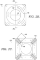
- FIG. 2A , 2B, and 2C which show various enlarged views of the spherical shell component 28 to further describe some structure of a spherical shell component 132.
- FIG. 2A is a perspective view and FIGS. 2B and 2C provide a plan view and cross-sectional view (respectively).
- the structure of the spherical shell component 132 includes a shell wall 133 ( FIG. 2C ) that is constructed from a series of ligaments 142, 144, 146, 148, and 150 (some ligaments may be obscured from view and do not have numbers).
- the ligaments are joined at ligament junctions, such as junctions 152, 154, and 156, in a networked manner to form the shell wall, which at least partially encloses a cavity 134.
- the ligaments include an inward facing surface 158 ( FIG. 2C ) that faces towards the cavity 134 and an outward facing surface 160 that faces away from the cavity 134.
- Each ligament includes a thickness 162 ( FIG. 2C ) that extends between the inward facing surface and the outward facing surface.
- the ligaments might be constructed of various materials, such as elastomers, EVA, TPU, and the like.
- the ligaments might be referred to as being elastic or having elastic properties that allow the ligaments to bend, stretch, fold, and the like, in response to an applied load.
- the shell wall also includes an array of circular voids 136 that are arranged throughout the shell wall and between the ligaments.
- Each circular void includes a first diameter 138 at the outward facing surfaces of ligaments that form a periphery around the void.
- each circular void includes a second diameter 140 at the inward facing surfaces of ligaments that form a periphery around the void.
- the first diameter 138 is larger than the second diameter 140, as illustrated in FIG. 2B .
- the voids arranged throughout the shell wall may be non-circular.
- the voids may include a polygon-shaped perimeter, such as four-sided voids or five-sided voids.
- the voids may have an organize-shaped perimeter. Similar to the arrangement discussed above, the void in the outward facing surface may be larger (e.g., larger area) than the void in the inward facing surface.
- the spherical shell component experiences a volume reduction when a load is applied. This volume reduction is brought about in part by a buckling cascade experienced by the ligaments, and the buckling of the ligaments absorbs at least part of the load (i.e., provides some impact attenuation). In addition, once ligaments have reached a substantially complete buckled state, the shell may compress as a whole to provide additional impact attenuation. Certain structural and geometric features of the spherical shell component help to provide the cascading buckling effect, which in turn provides impact attenuation.
- the number of holes in the array of holes is 6, 12, or 24, and this number of holes can affect the buckling and the impact-attenuation properties of the shell.
- the spherical shell component of FIGS. 2A - 2C is a six-hole spherical shell component, and for illustrative purposes a twelve-hole spherical shell component 232 is provided by FIG. 3A and a twenty-four-hole spherical shell component 332 is provided by FIG. 3B .
- each of these structures that are either six-hole, twelve-hole, or twenty-four-hole has octahedral symmetry.
- FIGS. 4A-4D depict the six-hole spherical shell component 132 at different stages of cooperative buckling.
- FIGS. 4A-4D collectively depict the progressive deformation and buckling of the ligaments at different stages and the resulting collapse of the circular voids.
- the amount of deformation, collapsing, and systematic volume reduction depends in a part on the magnitude of the load applied to the shell component.
- each of the ligaments debuckles and return to its original state (e.g., FIG. 4A ), in part due to the elastic nature of the material from which the shell component is constructed.
- the type or amount of compression or volume reduction of a spherical shell component may depend on a system in which the spherical shell component is integrated, including the other components of a footwear article (e.g., outsole and midsole mounting plate), as well as additional shell components.
- FIG. 1 depicts a system including other footwear components in which the spherical shell component 28 is integrated into the shoe bottom unit 12 and is coupled between the outsole 22A and the plate 26.
- the attachment of the spherical shell component 28 to other portions of the shoe that have a different structure may affect the amount or type of volume reduction or ligament-buckling cascade of the spherical shell component.
- the volume reduction may not be uniformly isotropic and/or the buckling of each ligament may not be exactly uniform.
- a plurality of shell components may be combined into layers of stacked shell components that are stacked, and the combination of shell components may affect the buckling of individual shells included in the system.
- a combination of shell components is provided in FIG. 1 , in which the footwear article 10 includes a top layer 30A of twelve-hole shell components and a bottom layer 30B of twelve-hole shell components.
- the layers of shell components may be stacked or arranged in various types of structures, each of which may perform differently as a system.
- the shell components are arranged in a lattice structure, and various types of lattice structures might be employed.
- the lattice structures a based on cubic crystal systems.
- a plurality of six-hole shell components may be stacked and layered in a body-centered cubic lattice between the outsole 22B and the plate 26; a plurality of twelve-hole shell components may be stacked and layered in a body-centered cubic lattice or in a simple cubic lattice between the outsole 22B and the plate 26; and a plurality of twenty-four-hole shell components may be stacked and layered in a body-centered cubic lattice, a face-centered cubic lattice, or in a simple cubic lattice between the outsole 22B and the plate 26.
- the amount of impact attenuation provided by a shell component is tunable by adjusting various shell characteristics, such as the ligament thickness between the inward and outward facing surfaces and/or the length of the first and second diameters of the voids.
- various shell characteristics such as the ligament thickness between the inward and outward facing surfaces and/or the length of the first and second diameters of the voids.
- thicker ligaments may provide a "stiffer" shell component and/or a more responsive shell component.
- the cavity 134 may be at least partially filled or occupied by another cushioning structure, which may also selectively tune the amount of impact attenuation provided by the shell.
- one or more voids between the shell components may also (or alternatively) be at least partially filled or occupied by another element, which may also selectively tune the amount of impact attenuation provided by the shell. Filling or occupying the cavity may provide additional functionality as well, such as by impeding foreign objects from being lodged in the cavity and by supporting and reinforcing the ligaments.
- the cavity-occupying element may include one or more properties that cooperate with the shell component to achieve an amount of impact attenuation, cushion, responsiveness, and the like.
- the filler element includes a density that is not so high as to prevent any buckling or collapsing action by the shell component and that is not so low as to allow unimpeded buckling by the shell component.
- the filler element may include a resilience selected to either increase or decrease the responsiveness (e.g., bounce back) of the shell component and of the system as a whole.
- the filler element may have a higher resilience than the shell component, such that the filler element actively increases the responsiveness of the shell component after buckling.
- the filler element may have a lower resilience than the shell component, in which case the filler element may dampen the responsiveness of the shell component after buckling.
- the cavity (or the voids between the shell components) may be occupied by another structural element having a unique cushion and resilience profile different than the shell component.
- the cavity may be occupied by a spring element, columnar impact attenuator, smaller shell component, and the like.
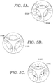
- FIGS. 5A, 5B, and 5C some illustrative filler elements, or cavity-occupying elements are depicted.
- the cavity of the shell component 510A is filled or occupied by a core 512A, which may have various properties (e.g., density, resilience, elasticity, etc.) selected to cooperate with the impact-attenuation of the shell component 510A.
- the core 512A may be comprised of a foamed material or other material having a density that is not so high as to prevent any buckling or collapsing action by the shell component and that is not so low as to allow unimpeded buckling by the shell component.
- the core 512A may be a separate structure that is inserted into the cavity by passing the core 512A through one of the voids.
- the core 512A may be integrally formed with the ligaments and from the same material as the ligaments.
- a core element may be round, as depicted in FIG. 5A , or may include other geometries, as well.
- a cavity of a shell component 510B is occupied by a core 512B, which also includes a boss or other structure configured to nest within the void in the shell wall.
- the core 512B may be formed from a material similar to the core 512A, such as a foamed material, or other material, having properties (e.g., density, resilience, elasticity, etc.) that cooperate with, and tune the functionality of, the shell component 510B.
- a cavity of a shell component 510C may be occupied by, or constructed to include, a filled bladder 512C.
- the filled bladder 512C may be a fluid-filled bladder (e.g., gas or liquid filled) or may include a fill of a solidified material. Again, the filled bladder may have various properties (e.g., density, resilience, elasticity, etc.) selected to cooperate with the properties of the shell component.
- a footwear article may include different types of shell components within the same midsole.
- FIG. 1 depicts an exemplary midsole in which the heel region 20 includes a series of six-hole shell components arranged in a single layer between the outsole 22A and the plate 26, and the forefoot region 16 includes a series of twelve-hole shell components arranged in a double-layered lattice between the outsole 22B and the plate 26.
- the twelve-hole shell components 30 are smaller than the six-hole shell components 28.
- a footwear article may include shell components having different arrangements and characteristics than those depicted in FIG. 1 .
- the shell components that are included in the midsole may be substantially uniform throughout by having a same number of circular voids and having a same shell diameter. These shell components that are substantially uniform may be positioned in one or more regions of the midsole.
- the shell components that are substantially uniform may be positioned in the heel portion or in the mid-foot portion or in the forefoot portion.
- the shell components that are substantially uniform may be positioned in both the heel portion and the forefoot portion, or in both the heel portion and the mid-foot portion, or in both the mid-foot portion and the forefoot portion.
- the shell components that are substantially uniform may be positioned in the heel portion, in the mid-foot portion, and the forefoot portion, such that the substantially uniform shell components are positioned in all three of the regions, extending from near the anterior portion of the shoe to the posterior portion of the shoe.
- one portion of the midsole may include one or more shell components having a first set of characteristics
- another portion of the midsole may include one or more shell components having a second set of characteristics, which is different from the first set of characteristics.
- the first set of characteristics and the second characteristics may be different from one another in one or more aspects, including but not limited to number of holes, shell size (e.g., shell diameter), hole size, lattice type, ligament thickness, ligament width (i.e., distance between circular voids), lack of filler, presence of filler, different filler properties, and any combination thereof.
- the heel portion may have a first set of shell components having a first set of characteristics
- the forefoot portion may have a second set of shell components having a second set of characteristics different from the first.
- the differences between the sets of characteristics may arise from various characteristics, including but not limited to a different number of holes, different hole size, different shell size, different lattice, different ligament thickness, different ligament width, presence of filler, different filler, or any combination of two or more of these differences.
- the mid-foot portion may have a third set of shell components having a third set of characteristics.
- the third set of characteristics may be the same as the first set or the same as the second set, or the third set of characteristics may be different from both the first set and the second set in any of the respects already described.
- the shell components within a same general region of the shoe may vary.
- a heel portion may include one shell component on a medial side that includes a first set of characteristics and another shell component on a lateral side that includes a second set of characteristics that is different from the first set of characteristics.
- the mid-foot and forefoot portions may likewise include varied shell components within the same general region.
- the medial and lateral portions of a region e.g., heel, mid-foot, and/or forefoot
- Variations in shell characteristics within a same region may arise from various characteristics, including but not limited to a different number of holes, different hole size, different shell size, different lattice, different ligament thickness, different ligament width, presence of filler, different filler, or any combination of two or more of these differences.
- the shell properties may gradually change from one portion of the footwear to another portion of the footwear.
- the shell properties may gradually change from the medial side of the midsole to the lateral side of the midsole.
- the shell properties may gradually change from the heel portion to the mid-foot portion and/or from the mid-foot portion to the forefoot portion.
- the shell properties may change from one portion of the shell to another portion of the shell.
- one side of the shell may have ligaments having a first thickness and geometry, which may gradually change as the network of ligaments transition to an opposing side of the shell.
- the hole size within a single shell component may vary between two different holes constructed into the single shell component.
- this variability of the shell component is usable to tune the performance of the midsole for an amount of impact-attenuation, an amount of responsiveness, and placement of impact-attenuation (e.g., lateral, medial, heel, forefoot, mid-foot, etc.).
- the shell components may be combined with one or more other midsole structures.
- shell components may be arranged in the heel portion of the midsole, and the forefoot and mid-foot portions might include another type of impact-attenuation structure (e.g., foam, spring, fluid-filled chamber, and the like).
- the shell components are arranged in a cartridge that is insertable and retainable between the outsole and another portion of the sole structure.
- FIG. 1 depicts a footwear article having an upper 14 and a shoe bottom unit 12
- other aspects of the present technology may be directed to the sole structure or shoe bottom unit without the upper.
- another aspect is directed to a midsole portion that includes shell components and that can be combined with other sole components to construct a shoe bottom unit.
- a further aspect includes a shoe bottom unit (e.g. outsole and midsole) that includes shell components and that can be coupled with an upper.
- some aspects may not include the upper or certain portions of the outsole or certain parts of the midsole.
- the round shell components might be manufactured using various techniques.
- the shell components might be 3D printed using an additive technique or laser sintered.
- the shell component may be molded or cast.
- the shell is injection molded around a dissolvable core, which is dissolved after the ligaments are formed.
- a cushioning structure for a midsole may take various forms, such as a cushioning structure for a midsole, a cushioning system for a midsole, a midsole for a footwear article, a footwear article, any combination thereof, and one or more methods of making each of these aspects or making any combination thereof.
- Other aspects include a method of tuning a cushioning structure for a midsole, as well as a method of tuning a cushioning system for a midsole.
- subject matter of this disclosure is directed to a sole for a footwear article, the sole including a plurality of round shell components (e.g., 2A, 3A, and 3B).
- Each round shell component in the plurality of round shell components includes ligaments that are connected at ligament junctions in a networked manner to collectively form a round three-dimensional body having a cavity.
- Each ligament includes an interior surface facing towards the cavity and an exterior surface facing away from the cavity and each ligament includes a ligament thickness extending between the interior surface and the exterior surface.
- each round shell component includes an array of voids positioned between the ligaments. Each void in the array of voids extends entirely from the exterior surface to the interior surface and includes a first void size at the exterior surface and a second void size at the interior surface.
- subject matter herein is directed to a cushioning system for a footwear midsole, the cushioning system including a first set of round shell components and a second set of round shell components.
- Each round shell component in the first and second set includes ligaments that are connected at ligament junctions in a networked manner to collectively form a round three-dimensional body having a cavity.
- Each ligament includes an interior surface facing towards the cavity and an exterior surface facing away from the cavity, and each ligament includes a ligament thickness extending between the interior surface and the exterior surface.
- each round shell component includes an array of voids positioned between the ligaments, each void in the array of voids extending entirely from the exterior surface to the interior surface.
- Each round shell component in the first set of round shell components includes a first set of characteristics
- each round shell component in the second set of round shell components includes a second set of characteristics, which is different than the first set of characteristics.
- the reversibly collapsible shell wall includes ligaments that are connected at ligament junctions in a networked manner to collectively form a round three-dimensional body.
- the ligaments at least partially enclose a cushioning-component core, and each ligament includes an exterior surface facing away from the core.
- the reversibly collapsible shell wall also includes an array of voids positioned between the ligaments, each void in the array of voids extending from the exterior surface towards the cushioning-component core.
- the core may be hollow, such as depicted in FIGS. 2A, 3A , and 4A .
- the core may include a foamed material, or a filled bladder (e.g., FIGS. 5A, 5B, and 5C ).
Description
- This disclosure relates to a footwear article, to a sole structure for the footwear article, and to a cushioning system for a footwear article.
-
US2015/033579 discloses an article of footwear including an upper and a support assembly positioned beneath the upper, and having a top plate, a bottom plate, and a plurality of connecting members. The connecting members are spaced from one another and extend partway inwardly from a periphery of the support assembly such that connecting members on a medial side of the support assembly are spaced from connecting members on a lateral side of the support assembly, with each connecting member including a primary aperture extending therethrough. Each of a plurality of tubular members has a central aperture passing therethrough and is received in the primary aperture of one of the connecting members. - The invention discloses a sole as defined in independent claim 1. Preferred embodiments are defined in the dependent claims.
- This disclosure is related to, among other things, a cushioning element for a footwear article, a cushioning system, a sole (e.g., midsole), a footwear article, a method of making any of the foregoing, and any combination thereof. Aspects described in this disclosure are defined by the claims below, not this summary. A high-level overview of various aspects of the disclosure is provided here to introduce a selection of concepts that are further described below in the detailed-description section. This summary is not intended to identify key features or essential features of the claimed subject matter, nor is it intended to be used as an aid in isolation to determine the scope of the claimed subject matter.
- This technology is described in detail herein with reference to the attached drawing figures, which are incorporated herein by reference, wherein:
-
FIG. 1 depicts a side view of a footwear article in accordance with an aspect of this disclosure; -
FIG. 2A ,2B, and 2C depict different views of a six-hole shell component in accordance with an aspect of this disclosure; -
FIG. 3A depicts a twelve-hole shell component in accordance with an aspect of this disclosure; -
FIG. 3B depicts a twenty-four-hole shell component in accordance with an aspect of this disclosure; -
FIGS. 4A - 4D depict the shell component ofFIGS. 2A ,2B, and 2C in various states of buckling in accordance with an aspect of this disclosure; and -
FIGS. 5A - 5C depict alternative shell components, each of which includes a respective additional impact-attenuation element in accordance with some aspects of this disclosure. - Subject matter is described throughout this Specification in detail and with specificity in order to meet statutory requirements.
- Upon reading the present disclosure, alternative aspects may become apparent to ordinary skilled artisans that practice in areas relevant to the described aspects, without departing from the scope of the claims.
- It will be understood that certain features and subcombinations are of utility and may be employed without reference to other features and subcombinations. This is contemplated by, and is within the scope of, the claims.
- The subject matter described in this Specification generally relates to a sole structure and cushioning system for a footwear article, the sole structure including one or more round shell elements that attenuate a force or impact. An exemplary footwear article is depicted in
FIG. 1 . At a high level, shell components (e.g., shell component 28) attenuate the force or impact by mechanically deforming or changing states (e.g., buckling), and further aspects will be described in more detail in other parts of this Specification. AlthoughFIG. 1 depicts one arrangement of various types of shell components, in other aspects of the technology the shell components may have different sizes, different hole patterns, and/or different layering structures than those depicted inFIG. 1 . Moreover, the illustrative figures depict, and the Specification describes, certain styles of footwear, such as footwear worn when engaging in athletic activities (e.g., basketball shoes, cross-training shoes, running shoes, and the like). But the subject matter described herein may be used in combination with other styles of footwear, such as dress shoes, sandals, loafers, boots, and the like. - In
FIG. 1 , thefootwear article 10 includes ashoe bottom unit 12 and an upper 14. The upper 14 and theshoe bottom unit 12 generally form a foot-receiving space that encloses at least part of a foot when the footwear is worn or donned. The foot-receiving space is accessible by inserting a foot through an opening formed by theankle collar 13. When describing various aspects of thefootwear 10, relative terms may be used to aid in understanding relative positions. For instance, thefootwear 10 may be divided into three general regions: aforefoot region 16, amid-foot region 18, and aheel region 20. Thefootwear 10 also includes a lateral side, a medial side, a superior portion, and an inferior portion. Theforefoot region 16 generally includes portions of thefootwear 10 corresponding with the toes and the joints connecting the metatarsals with the phalanges. Themid-foot region 18 generally includes portions offootwear 10 corresponding with the arch area of the foot, and theheel region 20 corresponds with rear portions of the foot, including the calcaneus bone. The lateral side and the medial side extend through each ofregions footwear 10. More particularly, the lateral side corresponds with an outside area of the foot (i.e., the surface that faces away from the other foot), and the medial side corresponds with an inside area of the foot (i.e., the surface that faces toward the other foot). Further, the superior portion and the inferior portion also extend through each of theregions regions footwear 10. They are intended to represent general areas offootwear 10 to aid in understanding the various descriptions provided in this Specification. In addition, the regions, sides, and portions are provided for explanatory and illustrative purposes and are not meant to require a human being for interpretive purposes. - A
shoe bottom unit 12 often comprises a shoe sole assembly with multiple components. For example, ashoe bottom unit 12 may comprise an outsole made of a relatively hard and durable material, such as rubber, that contacts the ground, floor, or other surface. Ashoe bottom unit 12 may further comprise a midsole formed from a material that provides cushioning and absorbs/attenuates force during normal wear and/or athletic training or performance. Examples of materials often used in midsoles are, for example, ethylene vinyl acetate (EVA), thermoplastic polyurethane (TPU), thermoplastic elastomer (e.g., polyether block amide), and the like. Shoe soles may further have additional components, such as additional cushioning components (such as springs, air bags, and the like), functional components (such as motion control elements to address pronation or supination), protective elements (such as resilient plates to prevent damage to the foot from hazards on the floor or ground), and the like. - In
FIG. 1 , an exemplaryshoe bottom unit 12 is depicted that includes anoutsole midsole midsole plate 26 to which portions of the upper 14 might attach to anchor the upper 14 to theshoe bottom unit 12. As previously indicated, an aspect of the present technology includes amidsole spherical shell components - A spherical shell component, such as
elements shoe bottom unit 12 undergoes a structural transformation induced by buckling under a load, such as when theshoe 10 is worn and a person is standing, walking, running, jumping, etc. This structural transformation may be described in various manners. For example, in one aspect the spherical shell component is a three-dimensional (3D) auxetic structure, and the structural transformation includes an isotropic volume reduction brought about by the buckling under load. In this description, the term "auxetic" describes a structure that experiences a contraction under load in a direction that is transverse to the load. This is in contrast to non-auxetic materials that typically expand in a direction orthogonal to an applied load. The term "spherical" is used in various parts of this Specification to describe a three-dimensional body that is generally round but not necessarily perfectly round. That is, "spherical" does not necessarily mean that any given point on the body is the same distance from the center of the body. - The volume reduction of the spherical shell components under load is at least partially brought about by the structure of the spherical shell components. In this sense the spherical shell components are at least partially a metamaterial, such that the impact-attenuation functionality is derived from characteristics other than the underlying material (e.g., EVA or TPU) - although the characteristics of the underlying material may also contribute to the impact-attenuation functionality.
- Reference is made to
FIG. 2A ,2B, and 2C (which show various enlarged views of the spherical shell component 28) to further describe some structure of aspherical shell component 132.FIG. 2A is a perspective view andFIGS. 2B and 2C provide a plan view and cross-sectional view (respectively). Generally, the structure of thespherical shell component 132 includes a shell wall 133 (FIG. 2C ) that is constructed from a series ofligaments junctions cavity 134. In addition, the ligaments include an inward facing surface 158 (FIG. 2C ) that faces towards thecavity 134 and an outward facingsurface 160 that faces away from thecavity 134. Each ligament includes a thickness 162 (FIG. 2C ) that extends between the inward facing surface and the outward facing surface. The ligaments might be constructed of various materials, such as elastomers, EVA, TPU, and the like. In addition, the ligaments might be referred to as being elastic or having elastic properties that allow the ligaments to bend, stretch, fold, and the like, in response to an applied load. - The shell wall also includes an array of
circular voids 136 that are arranged throughout the shell wall and between the ligaments. Each circular void includes afirst diameter 138 at the outward facing surfaces of ligaments that form a periphery around the void. In addition, each circular void includes asecond diameter 140 at the inward facing surfaces of ligaments that form a periphery around the void. In one aspect, thefirst diameter 138 is larger than thesecond diameter 140, as illustrated inFIG. 2B . - In other aspects of the disclosure, the voids arranged throughout the shell wall may be non-circular. For example, the voids may include a polygon-shaped perimeter, such as four-sided voids or five-sided voids. In addition, the voids may have an organize-shaped perimeter. Similar to the arrangement discussed above, the void in the outward facing surface may be larger (e.g., larger area) than the void in the inward facing surface.
- As previously described, the spherical shell component experiences a volume reduction when a load is applied. This volume reduction is brought about in part by a buckling cascade experienced by the ligaments, and the buckling of the ligaments absorbs at least part of the load (i.e., provides some impact attenuation). In addition, once ligaments have reached a substantially complete buckled state, the shell may compress as a whole to provide additional impact attenuation. Certain structural and geometric features of the spherical shell component help to provide the cascading buckling effect, which in turn provides impact attenuation. For example, in an aspect of the technology the number of holes in the array of holes is 6, 12, or 24, and this number of holes can affect the buckling and the impact-attenuation properties of the shell. The spherical shell component of
FIGS. 2A - 2C is a six-hole spherical shell component, and for illustrative purposes a twelve-holespherical shell component 232 is provided byFIG. 3A and a twenty-four-holespherical shell component 332 is provided byFIG. 3B . In a further aspect, each of these structures that are either six-hole, twelve-hole, or twenty-four-hole has octahedral symmetry. - For illustrative purposes,
FIGS. 4A-4D depict the six-holespherical shell component 132 at different stages of cooperative buckling.FIGS. 4A-4D collectively depict the progressive deformation and buckling of the ligaments at different stages and the resulting collapse of the circular voids. The amount of deformation, collapsing, and systematic volume reduction depends in a part on the magnitude of the load applied to the shell component. When the load is removed, each of the ligaments debuckles and return to its original state (e.g.,FIG. 4A ), in part due to the elastic nature of the material from which the shell component is constructed. - The type or amount of compression or volume reduction of a spherical shell component may depend on a system in which the spherical shell component is integrated, including the other components of a footwear article (e.g., outsole and midsole mounting plate), as well as additional shell components. For example,
FIG. 1 depicts a system including other footwear components in which thespherical shell component 28 is integrated into theshoe bottom unit 12 and is coupled between theoutsole 22A and theplate 26. Thus the attachment of thespherical shell component 28 to other portions of the shoe that have a different structure (e.g., possibly non-auxetic) may affect the amount or type of volume reduction or ligament-buckling cascade of the spherical shell component. For instance, the volume reduction may not be uniformly isotropic and/or the buckling of each ligament may not be exactly uniform. - In other systems, a plurality of shell components may be combined into layers of stacked shell components that are stacked, and the combination of shell components may affect the buckling of individual shells included in the system. In example of a combination of shell components is provided in
FIG. 1 , in which thefootwear article 10 includes atop layer 30A of twelve-hole shell components and abottom layer 30B of twelve-hole shell components. The layers of shell components may be stacked or arranged in various types of structures, each of which may perform differently as a system. For example, in one aspect the shell components are arranged in a lattice structure, and various types of lattice structures might be employed. In one aspect the lattice structures a based on cubic crystal systems. For example, a plurality of six-hole shell components may be stacked and layered in a body-centered cubic lattice between theoutsole 22B and theplate 26; a plurality of twelve-hole shell components may be stacked and layered in a body-centered cubic lattice or in a simple cubic lattice between theoutsole 22B and theplate 26; and a plurality of twenty-four-hole shell components may be stacked and layered in a body-centered cubic lattice, a face-centered cubic lattice, or in a simple cubic lattice between theoutsole 22B and theplate 26. - In addition, the amount of impact attenuation provided by a shell component is tunable by adjusting various shell characteristics, such as the ligament thickness between the inward and outward facing surfaces and/or the length of the first and second diameters of the voids. For example, thicker ligaments may provide a "stiffer" shell component and/or a more responsive shell component.
- In some other aspects of the disclosure depicted by
FIGS. 5A, 5B, and 5C , thecavity 134 may be at least partially filled or occupied by another cushioning structure, which may also selectively tune the amount of impact attenuation provided by the shell. Similarly, one or more voids between the shell components may also (or alternatively) be at least partially filled or occupied by another element, which may also selectively tune the amount of impact attenuation provided by the shell. Filling or occupying the cavity may provide additional functionality as well, such as by impeding foreign objects from being lodged in the cavity and by supporting and reinforcing the ligaments. - In one aspect the cavity-occupying element may include one or more properties that cooperate with the shell component to achieve an amount of impact attenuation, cushion, responsiveness, and the like. For example, in one aspect the filler element includes a density that is not so high as to prevent any buckling or collapsing action by the shell component and that is not so low as to allow unimpeded buckling by the shell component. In addition, the filler element may include a resilience selected to either increase or decrease the responsiveness (e.g., bounce back) of the shell component and of the system as a whole. For example, the filler element may have a higher resilience than the shell component, such that the filler element actively increases the responsiveness of the shell component after buckling. In another example, the filler element may have a lower resilience than the shell component, in which case the filler element may dampen the responsiveness of the shell component after buckling. In another aspect, the cavity (or the voids between the shell components) may be occupied by another structural element having a unique cushion and resilience profile different than the shell component. For example, the cavity may be occupied by a spring element, columnar impact attenuator, smaller shell component, and the like.
- Referring to
FIGS. 5A, 5B, and 5C some illustrative filler elements, or cavity-occupying elements are depicted. For example, inFIG. 5A the cavity of theshell component 510A is filled or occupied by acore 512A, which may have various properties (e.g., density, resilience, elasticity, etc.) selected to cooperate with the impact-attenuation of theshell component 510A. Thecore 512A may be comprised of a foamed material or other material having a density that is not so high as to prevent any buckling or collapsing action by the shell component and that is not so low as to allow unimpeded buckling by the shell component. Thecore 512A may be a separate structure that is inserted into the cavity by passing thecore 512A through one of the voids. Alternatively, thecore 512A may be integrally formed with the ligaments and from the same material as the ligaments. A core element may be round, as depicted inFIG. 5A , or may include other geometries, as well. For example, inFIG. 5B a cavity of ashell component 510B is occupied by acore 512B, which also includes a boss or other structure configured to nest within the void in the shell wall. The core 512B may be formed from a material similar to thecore 512A, such as a foamed material, or other material, having properties (e.g., density, resilience, elasticity, etc.) that cooperate with, and tune the functionality of, theshell component 510B. In another example illustrated byFIG. 5C , a cavity of a shell component 510C may be occupied by, or constructed to include, a filledbladder 512C. The filledbladder 512C may be a fluid-filled bladder (e.g., gas or liquid filled) or may include a fill of a solidified material. Again, the filled bladder may have various properties (e.g., density, resilience, elasticity, etc.) selected to cooperate with the properties of the shell component. - As depicted in
FIG. 1 , a footwear article may include different types of shell components within the same midsole. For example,FIG. 1 depicts an exemplary midsole in which theheel region 20 includes a series of six-hole shell components arranged in a single layer between theoutsole 22A and theplate 26, and theforefoot region 16 includes a series of twelve-hole shell components arranged in a double-layered lattice between theoutsole 22B and theplate 26. InFIG. 1 the twelve-hole shell components 30 are smaller than the six-hole shell components 28. - In other aspects of the technology, a footwear article may include shell components having different arrangements and characteristics than those depicted in
FIG. 1 . For example, the shell components that are included in the midsole may be substantially uniform throughout by having a same number of circular voids and having a same shell diameter. These shell components that are substantially uniform may be positioned in one or more regions of the midsole. For example, the shell components that are substantially uniform may be positioned in the heel portion or in the mid-foot portion or in the forefoot portion. Alternatively, the shell components that are substantially uniform may be positioned in both the heel portion and the forefoot portion, or in both the heel portion and the mid-foot portion, or in both the mid-foot portion and the forefoot portion. Further, the shell components that are substantially uniform may be positioned in the heel portion, in the mid-foot portion, and the forefoot portion, such that the substantially uniform shell components are positioned in all three of the regions, extending from near the anterior portion of the shoe to the posterior portion of the shoe. - Other aspects of the technology may include other variations from
FIG. 1 . For example, one portion of the midsole may include one or more shell components having a first set of characteristics, and another portion of the midsole may include one or more shell components having a second set of characteristics, which is different from the first set of characteristics. The first set of characteristics and the second characteristics may be different from one another in one or more aspects, including but not limited to number of holes, shell size (e.g., shell diameter), hole size, lattice type, ligament thickness, ligament width (i.e., distance between circular voids), lack of filler, presence of filler, different filler properties, and any combination thereof. - Various strategies may be utilized to apply the variability of shell characteristics from one portion of the midsole to another portion of the midsole, either fore-to-aft or medial-to-lateral. For instance, the heel portion may have a first set of shell components having a first set of characteristics, and the forefoot portion may have a second set of shell components having a second set of characteristics different from the first. The differences between the sets of characteristics may arise from various characteristics, including but not limited to a different number of holes, different hole size, different shell size, different lattice, different ligament thickness, different ligament width, presence of filler, different filler, or any combination of two or more of these differences. Furthermore, the mid-foot portion may have a third set of shell components having a third set of characteristics. The third set of characteristics may be the same as the first set or the same as the second set, or the third set of characteristics may be different from both the first set and the second set in any of the respects already described. These various combinations of different and/or similar sets of characteristics in different parts of the sole are only exemplary and are not meant to be exhaustive. Any combination of similar or different characteristics in the heel portion, mid-foot portion, and forefoot portion is intended to be included within the scope of this technology.
- In a further aspect, the shell components within a same general region of the shoe may vary. For example, a heel portion may include one shell component on a medial side that includes a first set of characteristics and another shell component on a lateral side that includes a second set of characteristics that is different from the first set of characteristics. The mid-foot and forefoot portions may likewise include varied shell components within the same general region. In another example, the medial and lateral portions of a region (e.g., heel, mid-foot, and/or forefoot) may be the same or similar, and a central portion of the region, between the medial and lateral portions, may vary. Variations in shell characteristics within a same region may arise from various characteristics, including but not limited to a different number of holes, different hole size, different shell size, different lattice, different ligament thickness, different ligament width, presence of filler, different filler, or any combination of two or more of these differences.
- In other aspects, the shell properties (e.g., size, hole number, hole size, material, ligament thickness, ligament width, lattice structure, filler, filler type, void structure, void fill, number of layers, etc.) may gradually change from one portion of the footwear to another portion of the footwear. For instance, the shell properties may gradually change from the medial side of the midsole to the lateral side of the midsole. In addition, the shell properties may gradually change from the heel portion to the mid-foot portion and/or from the mid-foot portion to the forefoot portion.
- In a further aspect, the shell properties may change from one portion of the shell to another portion of the shell. For example, one side of the shell may have ligaments having a first thickness and geometry, which may gradually change as the network of ligaments transition to an opposing side of the shell. In this sense, the hole size within a single shell component may vary between two different holes constructed into the single shell component.
- In an aspect of the technology, this variability of the shell component is usable to tune the performance of the midsole for an amount of impact-attenuation, an amount of responsiveness, and placement of impact-attenuation (e.g., lateral, medial, heel, forefoot, mid-foot, etc.).
- The shell components may be combined with one or more other midsole structures. For example, shell components may be arranged in the heel portion of the midsole, and the forefoot and mid-foot portions might include another type of impact-attenuation structure (e.g., foam, spring, fluid-filled chamber, and the like). In one aspect, the shell components are arranged in a cartridge that is insertable and retainable between the outsole and another portion of the sole structure.
- Although
FIG. 1 depicts a footwear article having an upper 14 and ashoe bottom unit 12, other aspects of the present technology may be directed to the sole structure or shoe bottom unit without the upper. For example, another aspect is directed to a midsole portion that includes shell components and that can be combined with other sole components to construct a shoe bottom unit. Additionally, a further aspect includes a shoe bottom unit (e.g. outsole and midsole) that includes shell components and that can be coupled with an upper. Thus, some aspects may not include the upper or certain portions of the outsole or certain parts of the midsole. - The round shell components (e.g., 132, 232, and 332) might be manufactured using various techniques. For example, the shell components might be 3D printed using an additive technique or laser sintered. In addition, the shell component may be molded or cast. In one aspect, the shell is injection molded around a dissolvable core, which is dissolved after the ligaments are formed.
- Subject matter set forth in this disclosure, and covered by at least some of the claims, may take various forms, such as a cushioning structure for a midsole, a cushioning system for a midsole, a midsole for a footwear article, a footwear article, any combination thereof, and one or more methods of making each of these aspects or making any combination thereof. Other aspects include a method of tuning a cushioning structure for a midsole, as well as a method of tuning a cushioning system for a midsole.
- In one aspect, subject matter of this disclosure is directed to a sole for a footwear article, the sole including a plurality of round shell components (e.g., 2A, 3A, and 3B). Each round shell component in the plurality of round shell components includes ligaments that are connected at ligament junctions in a networked manner to collectively form a round three-dimensional body having a cavity. Each ligament includes an interior surface facing towards the cavity and an exterior surface facing away from the cavity and each ligament includes a ligament thickness extending between the interior surface and the exterior surface. In addition, each round shell component includes an array of voids positioned between the ligaments. Each void in the array of voids extends entirely from the exterior surface to the interior surface and includes a first void size at the exterior surface and a second void size at the interior surface.
- In a further aspect, subject matter herein is directed to a cushioning system for a footwear midsole, the cushioning system including a first set of round shell components and a second set of round shell components. Each round shell component in the first and second set includes ligaments that are connected at ligament junctions in a networked manner to collectively form a round three-dimensional body having a cavity. Each ligament includes an interior surface facing towards the cavity and an exterior surface facing away from the cavity, and each ligament includes a ligament thickness extending between the interior surface and the exterior surface. Moreover, each round shell component includes an array of voids positioned between the ligaments, each void in the array of voids extending entirely from the exterior surface to the interior surface. Each round shell component in the first set of round shell components includes a first set of characteristics, and each round shell component in the second set of round shell components includes a second set of characteristics, which is different than the first set of characteristics.
- Another aspect of the disclosure is directed to a cushioning component for a footwear midsole, the cushioning component including a reversibly collapsible shell wall. The reversibly collapsible shell wall includes ligaments that are connected at ligament junctions in a networked manner to collectively form a round three-dimensional body. The ligaments at least partially enclose a cushioning-component core, and each ligament includes an exterior surface facing away from the core. The reversibly collapsible shell wall also includes an array of voids positioned between the ligaments, each void in the array of voids extending from the exterior surface towards the cushioning-component core. In some instances, the core may be hollow, such as depicted in
FIGS. 2A, 3A , and4A . In other examples, the core may include a foamed material, or a filled bladder (e.g.,FIGS. 5A, 5B, and 5C ). - From the foregoing, it will be seen that subject matter described in this disclosure is adapted to attain all the ends and objects hereinabove set forth together with other advantages which are obvious and which are inherent to the structure. It will be understood that certain features and subcombinations are of utility and may be employed without reference to other features and subcombinations. This is contemplated by and is within the scope of the claims. Since many possible alternative versions may be made of the subject matter described herein, without departing from the scope of this disclosure, it is to be understood that all matter herein set forth or shown in the accompanying drawings is to be interpreted as illustrative and not in a limiting sense.
Claims (15)
- A sole (24A, 24B) for a footwear article (10), the sole (24A, 24B) comprising: a plurality of round shell components (28, 30, 132, 232, 332, 510A, 510B, 510C), each round shell component (28, 30, 132, 232, 332, 510A, 510B, 510C) in the plurality of round shell components (28, 30, 132, 232, 332, 510A, 510B, 510C) including: ligaments (142, 144, 146, 148, 150) that are connected at ligament junctions (512, 154, 156) in a networked manner to collectively form a round three-dimensional body having a cavity (134), each ligament (142, 144, 146, 148, 150) including an interior surface facing towards the cavity (134) and an exterior surface facing away from the cavity (134) and each ligament (142, 144, 146, 148, 150) including a ligament thickness extending between the interior surface and the exterior surface; characterised in that an array of voids (136) positioned between the ligaments (142, 144, 146, 148, 150), each void (136) in the array of voids (136) extending entirely from the exterior surface to the interior surface and including a first void size (138) at the exterior surface and a second void size (140) at the interior surface.
- The sole (24A, 24B) of claim 1, wherein the array of voids (136) includes a multiple of six voids (136) and the round three-dimensional body comprises octahedral symmetry.
- The sole (24A, 24B) of claim 1, wherein the first void size (138) is larger than the second void size (140).
- The sole (24A, 24B) of claim 3, wherein the voids (136) comprise circular voids and the first void size (138) includes a first diameter and the second void size (140) includes a second diameter.
- The sole (24A, 24B) of claim 1, wherein the first void size (138) and the second void size (140) are substantially similar.
- The sole (24A, 24B) of claim 1, wherein the plurality of round shell components (28, 30) includes a first set of round shell components (28) and a second set of round shell components (30), wherein each round shell component (28) in the first set of round shell components (28) includes a respective round three-dimensional body having a first volume, and wherein each round shell component (30) in the second set of round shell components (30) includes a respective round three-dimensional body having a second volume that is smaller than the first volume.
- The sole (24A, 24B) of claim 6, wherein the second set of round shell components (30) are arranged in a crystal structure having a cubic-lattice structure, and preferably wherein the first set of round shell components (28) are positioned in a heel portion (20) of the sole, and wherein the second set of round shell components (30) are arranged in a forefoot region (16) of the sole (24A, 24B).
- The sole (24A, 24B) of claim 1, wherein the plurality of round shell components (28, 30) includes a first set of round shell components (28) and a second set of round shell components (30), wherein each round shell component (28) in the first set of round shell components (28) includes a first array of voids having a first quantity of voids, and wherein each round shell component (30) in the second set of round shell components (30) includes a second array of voids having a second quantity of voids, which is greater than the first quantity and is a multiple of the first quantity.
- The sole (24A, 24B) of claim 1, wherein the sole (24A, 24B) includes a heel portion (20), a mid-foot portion (18), and a forefoot portion (16), and wherein the plurality of round shell components (142, 144, 146, 148, 150) are positioned in the heel portion (20), the mid-foot portion (18), the forefoot portion (16), or any combination thereof.
- The sole of claim 9, wherein the plurality of round shell components are positioned within the heel portion, wherein the plurality of round shell components positioned within the heel portion includes a first set of round shell components and a second set of round shell components, wherein each round shell component in the first set of round shell components includes a first set of characteristics, and wherein each round shell component in the second set of round shell components includes a second set of characteristics, which is different than the first set of characteristics.
- The sole of claim 9, wherein the plurality of round shell components are positioned within the mid-foot portion, wherein the plurality of round shell component positioned within the mid-foot portion includes a first set of round shell components and a second set of round shell components, wherein each round shell component in the first set of round shell components includes a first set of characteristics, and wherein each round shell component in the second set of round shell components includes a second set of characteristics, which is different than the first set of characteristics.
- The sole (24A, 24B) of claim 9, wherein the plurality of round shell components (30) are positioned within the forefoot portion (16), wherein the plurality of round shell components (30) positioned within the forefoot portion (16) includes a first set of round shell components (30A) and a second set of round shell components (30B), wherein each round shell component (30) in the first set of round shell components (30A) includes a first set of characteristics, and wherein each round shell component (30) in the second set of round shell components (30B) includes a second set of characteristics, which is different than the first set of characteristics.
- The sole of claim 9, wherein the plurality of round shell component are positioned within the heel portion, the mid-foot portion, and the forefoot portion and includes at least a first set of round shell components and a second set of round shell components, wherein each round shell component in the first set of round shell components includes a first set of characteristics, and wherein each round shell component in the second set of round shell components includes a second set of characteristics, which is different than the first set of characteristics.
- The sole (24A, 24B) of claim 1, wherein the cavity (134) is filled with another cushioning structure (512B, 512C), and wherein the other cushioning structure includes a foamed material (512B), a fluid-filled bladder (512C), or any combination thereof.
- The sole (24A, 24B) of claim 1, wherein the sole is a footwear midsole and the set of round shell components (28) are a first set of round shell components and comprise a cushioning system for the footwear midsole, wherein: the cushioning system further comprises a second set of round shell components (30); each round shell component (28) in the first set of round shell components includes a first set of characteristics; and each round shell component (30) in the second set of round shell components includes a second set of characteristics, which is different than the first set of characteristics.
Applications Claiming Priority (2)
| Application Number | Priority Date | Filing Date | Title |
|---|---|---|---|
| US201562255354P | 2015-11-13 | 2015-11-13 | |
| PCT/US2016/061601 WO2017083697A1 (en) | 2015-11-13 | 2016-11-11 | Footwear sole structure |
Publications (2)
| Publication Number | Publication Date |
|---|---|
| EP3373762A1 EP3373762A1 (en) | 2018-09-19 |
| EP3373762B1 true EP3373762B1 (en) | 2022-02-02 |
Family
ID=57396846
Family Applications (1)
| Application Number | Title | Priority Date | Filing Date |
|---|---|---|---|
| EP16801670.7A Active EP3373762B1 (en) | 2015-11-13 | 2016-11-11 | Footwear sole structure |
Country Status (5)
| Country | Link |
|---|---|
| US (1) | US10721990B2 (en) |
| EP (1) | EP3373762B1 (en) |
| JP (1) | JP6683813B2 (en) |
| CN (1) | CN108601421B (en) |
| WO (1) | WO2017083697A1 (en) |
Families Citing this family (24)
| Publication number | Priority date | Publication date | Assignee | Title |
|---|---|---|---|---|
| USD953709S1 (en) | 1985-08-29 | 2022-06-07 | Puma SE | Shoe |
| USD855953S1 (en) * | 2017-09-14 | 2019-08-13 | Puma SE | Shoe sole element |
| USD910290S1 (en) | 2017-09-14 | 2021-02-16 | Puma SE | Shoe |
| USD911682S1 (en) | 2017-09-14 | 2021-03-02 | Puma SE | Shoe |
| USD911683S1 (en) | 2017-09-14 | 2021-03-02 | Puma SE | Shoe |
| US9925440B2 (en) | 2014-05-13 | 2018-03-27 | Bauer Hockey, Llc | Sporting goods including microlattice structures |
| USD850766S1 (en) | 2017-01-17 | 2019-06-11 | Puma SE | Shoe sole element |
| US11399593B2 (en) * | 2017-05-25 | 2022-08-02 | Nike, Inc. | Article of footwear with auxetic sole structure having a filled auxetic aperture |
| ES2884263T3 (en) | 2017-08-11 | 2021-12-10 | Puma SE | Procedure for the manufacture of a shoe |
| USD975417S1 (en) | 2017-09-14 | 2023-01-17 | Puma SE | Shoe |
| US11832684B2 (en) | 2018-04-27 | 2023-12-05 | Puma SE | Shoe, in particular a sports shoe |
| EP3801106A1 (en) * | 2018-05-31 | 2021-04-14 | NIKE Innovate C.V. | Article with auxetic spaces and method of manufacturing |
| IT201800010239A1 (en) * | 2018-11-12 | 2020-05-12 | Geox Spa | PERFECTED SOLE OF FOOTWEAR |
| TWI703939B (en) * | 2019-02-22 | 2020-09-11 | 鄭正元 | Midsole structure for shoes and manufacturing method thereof |
| WO2020210395A1 (en) * | 2019-04-09 | 2020-10-15 | Hyperdamping Inc. | Materials having tunable properties, and related systems and method |
| WO2020232550A1 (en) | 2019-05-21 | 2020-11-26 | Bauer Hockey Ltd. | Helmets comprising additively-manufactured components |
| CN110811058A (en) * | 2019-12-12 | 2020-02-21 | 南京阿米巴工程结构优化研究院有限公司 | Hierarchical resilience structure that 3D printed and sole of using this structure |
| EP3841907B1 (en) * | 2019-12-27 | 2023-01-11 | ASICS Corporation | Shoe sole and shoe |
| WO2021155409A1 (en) * | 2020-01-30 | 2021-08-05 | University Of Washington | Axial auxetic structures |
| USD944504S1 (en) | 2020-04-27 | 2022-03-01 | Puma SE | Shoe |
| JP2022101228A (en) * | 2020-12-24 | 2022-07-06 | 株式会社アシックス | Sole and shoe |
| JP2023003758A (en) * | 2021-06-24 | 2023-01-17 | 株式会社アシックス | Shoe sole and shoe |
| JP2023003757A (en) * | 2021-06-24 | 2023-01-17 | 株式会社アシックス | Buffer material, sole and shoes |
| CN114668224A (en) * | 2022-04-28 | 2022-06-28 | 李宁(中国)体育用品有限公司 | Shock attenuation supporting element, shock attenuation supporting component and sole |
Family Cites Families (13)
| Publication number | Priority date | Publication date | Assignee | Title |
|---|---|---|---|---|
| DE4114551C2 (en) * | 1990-11-07 | 2000-07-27 | Adidas Ag | Shoe bottom, in particular for sports shoes |
| EP0526892A3 (en) * | 1991-08-07 | 1993-07-21 | Reebok International Ltd. | Midsole stabilizer |
| WO1999033641A1 (en) * | 1997-12-24 | 1999-07-08 | Molecular Geodesics, Inc. | Foam scaffold materials |
| US7314125B2 (en) * | 2004-09-27 | 2008-01-01 | Nike, Inc. | Impact attenuating and spring elements and products containing such elements |
| US7730635B2 (en) * | 2004-09-27 | 2010-06-08 | Nike, Inc. | Impact-attenuation members and products containing such members |
| US7458172B2 (en) * | 2004-09-27 | 2008-12-02 | Nike, Inc. | Impact attenuating devices and products containing such devices |
| JP4452721B2 (en) * | 2004-09-30 | 2010-04-21 | 株式会社アシックス | Shoe sole shock absorber |
| US7360324B2 (en) * | 2005-08-15 | 2008-04-22 | Nike, Inc. | Article of footwear with spherical support elements |
| US7877898B2 (en) | 2006-07-21 | 2011-02-01 | Nike, Inc. | Impact-attenuation systems for articles of footwear and other foot-receiving devices |
| US7685742B2 (en) * | 2006-07-21 | 2010-03-30 | Nike, Inc. | Impact-attenuation systems for articles of footwear and other foot-receiving devices |
| KR102137742B1 (en) * | 2012-12-19 | 2020-07-24 | 뉴우바란스아스레틱스인코포레이팃드 | Customized footwear, and method for designing and manufacturing same |
| US9456657B2 (en) * | 2013-07-31 | 2016-10-04 | Nike, Inc. | Article of footwear with support assembly having tubular members |
| EP3747299B1 (en) * | 2014-02-12 | 2023-10-11 | New Balance Athletics, Inc. | Sole for footwear, and methods for designing and manufacturing same |
-
2016
- 2016-11-11 JP JP2018524344A patent/JP6683813B2/en active Active
- 2016-11-11 WO PCT/US2016/061601 patent/WO2017083697A1/en active Application Filing
- 2016-11-11 EP EP16801670.7A patent/EP3373762B1/en active Active
- 2016-11-11 US US15/776,004 patent/US10721990B2/en active Active
- 2016-11-11 CN CN201680077970.9A patent/CN108601421B/en active Active
Also Published As
| Publication number | Publication date |
|---|---|
| US20180317600A1 (en) | 2018-11-08 |
| JP6683813B2 (en) | 2020-04-22 |
| US10721990B2 (en) | 2020-07-28 |
| JP2018536478A (en) | 2018-12-13 |
| CN108601421B (en) | 2021-02-12 |
| CN108601421A (en) | 2018-09-28 |
| EP3373762A1 (en) | 2018-09-19 |
| WO2017083697A1 (en) | 2017-05-18 |
Similar Documents
| Publication | Publication Date | Title |
|---|---|---|
| EP3373762B1 (en) | Footwear sole structure | |
| US10034516B2 (en) | Footwear sole structure | |
| US11877619B2 (en) | Footwear sole structure | |
| US20220240622A1 (en) | Particulate foam stacked casings | |
| US11284671B2 (en) | Article of footwear incorporating particulate matter | |
| CN107734990B (en) | Article of footwear with a cellular sole structure | |
| EP2929791B1 (en) | Article of footwear having an elevated plate sole structure | |
| EP2923595B1 (en) | Article of footwear having an elevated plate sole structure | |
| EP2937006B1 (en) | Article of footwear having an elevated plate sole structure | |
| CN110650645B (en) | Article of footwear including an auxetic sole structure with filled auxetic apertures | |
| AU2010299605B2 (en) | Multilayer insole to be fitted in footwear and the like | |
| EP3416514B1 (en) | Footwear sole structure |
Legal Events
| Date | Code | Title | Description |
|---|---|---|---|
| STAA | Information on the status of an ep patent application or granted ep patent |
Free format text: STATUS: UNKNOWN |
|
| STAA | Information on the status of an ep patent application or granted ep patent |
Free format text: STATUS: THE INTERNATIONAL PUBLICATION HAS BEEN MADE |
|
| PUAI | Public reference made under article 153(3) epc to a published international application that has entered the european phase |
Free format text: ORIGINAL CODE: 0009012 |
|
| STAA | Information on the status of an ep patent application or granted ep patent |
Free format text: STATUS: REQUEST FOR EXAMINATION WAS MADE |
|
| 17P | Request for examination filed |
Effective date: 20180510 |
|
| AK | Designated contracting states |
Kind code of ref document: A1 Designated state(s): AL AT BE BG CH CY CZ DE DK EE ES FI FR GB GR HR HU IE IS IT LI LT LU LV MC MK MT NL NO PL PT RO RS SE SI SK SM TR |
|
| AX | Request for extension of the european patent |
Extension state: BA ME |
|
| DAV | Request for validation of the european patent (deleted) | ||
| DAX | Request for extension of the european patent (deleted) | ||
| GRAP | Despatch of communication of intention to grant a patent |
Free format text: ORIGINAL CODE: EPIDOSNIGR1 |
|
| STAA | Information on the status of an ep patent application or granted ep patent |
Free format text: STATUS: GRANT OF PATENT IS INTENDED |
|
| INTG | Intention to grant announced |
Effective date: 20210812 |
|
| GRAS | Grant fee paid |
Free format text: ORIGINAL CODE: EPIDOSNIGR3 |
|
| GRAA | (expected) grant |
Free format text: ORIGINAL CODE: 0009210 |
|
| STAA | Information on the status of an ep patent application or granted ep patent |
Free format text: STATUS: THE PATENT HAS BEEN GRANTED |
|
| AK | Designated contracting states |
Kind code of ref document: B1 Designated state(s): AL AT BE BG CH CY CZ DE DK EE ES FI FR GB GR HR HU IE IS IT LI LT LU LV MC MK MT NL NO PL PT RO RS SE SI SK SM TR |
|
| REG | Reference to a national code |
Ref country code: GB Ref legal event code: FG4D |
|
| REG | Reference to a national code |
Ref country code: CH Ref legal event code: EP Ref country code: AT Ref legal event code: REF Ref document number: 1466353 Country of ref document: AT Kind code of ref document: T Effective date: 20220215 |
|
| REG | Reference to a national code |
Ref country code: DE Ref legal event code: R096 Ref document number: 602016068820 Country of ref document: DE |
|
| REG | Reference to a national code |
Ref country code: IE Ref legal event code: FG4D |
|
| REG | Reference to a national code |
Ref country code: LT Ref legal event code: MG9D |
|
| REG | Reference to a national code |
Ref country code: NL Ref legal event code: MP Effective date: 20220202 |
|
| REG | Reference to a national code |
Ref country code: AT Ref legal event code: MK05 Ref document number: 1466353 Country of ref document: AT Kind code of ref document: T Effective date: 20220202 |
|
| PG25 | Lapsed in a contracting state [announced via postgrant information from national office to epo] |
Ref country code: SE Free format text: LAPSE BECAUSE OF FAILURE TO SUBMIT A TRANSLATION OF THE DESCRIPTION OR TO PAY THE FEE WITHIN THE PRESCRIBED TIME-LIMIT Effective date: 20220202 Ref country code: RS Free format text: LAPSE BECAUSE OF FAILURE TO SUBMIT A TRANSLATION OF THE DESCRIPTION OR TO PAY THE FEE WITHIN THE PRESCRIBED TIME-LIMIT Effective date: 20220202 Ref country code: PT Free format text: LAPSE BECAUSE OF FAILURE TO SUBMIT A TRANSLATION OF THE DESCRIPTION OR TO PAY THE FEE WITHIN THE PRESCRIBED TIME-LIMIT Effective date: 20220602 Ref country code: NO Free format text: LAPSE BECAUSE OF FAILURE TO SUBMIT A TRANSLATION OF THE DESCRIPTION OR TO PAY THE FEE WITHIN THE PRESCRIBED TIME-LIMIT Effective date: 20220502 Ref country code: NL Free format text: LAPSE BECAUSE OF FAILURE TO SUBMIT A TRANSLATION OF THE DESCRIPTION OR TO PAY THE FEE WITHIN THE PRESCRIBED TIME-LIMIT Effective date: 20220202 Ref country code: LT Free format text: LAPSE BECAUSE OF FAILURE TO SUBMIT A TRANSLATION OF THE DESCRIPTION OR TO PAY THE FEE WITHIN THE PRESCRIBED TIME-LIMIT Effective date: 20220202 Ref country code: HR Free format text: LAPSE BECAUSE OF FAILURE TO SUBMIT A TRANSLATION OF THE DESCRIPTION OR TO PAY THE FEE WITHIN THE PRESCRIBED TIME-LIMIT Effective date: 20220202 Ref country code: ES Free format text: LAPSE BECAUSE OF FAILURE TO SUBMIT A TRANSLATION OF THE DESCRIPTION OR TO PAY THE FEE WITHIN THE PRESCRIBED TIME-LIMIT Effective date: 20220202 Ref country code: BG Free format text: LAPSE BECAUSE OF FAILURE TO SUBMIT A TRANSLATION OF THE DESCRIPTION OR TO PAY THE FEE WITHIN THE PRESCRIBED TIME-LIMIT Effective date: 20220502 |
|
| PG25 | Lapsed in a contracting state [announced via postgrant information from national office to epo] |
Ref country code: PL Free format text: LAPSE BECAUSE OF FAILURE TO SUBMIT A TRANSLATION OF THE DESCRIPTION OR TO PAY THE FEE WITHIN THE PRESCRIBED TIME-LIMIT Effective date: 20220202 Ref country code: LV Free format text: LAPSE BECAUSE OF FAILURE TO SUBMIT A TRANSLATION OF THE DESCRIPTION OR TO PAY THE FEE WITHIN THE PRESCRIBED TIME-LIMIT Effective date: 20220202 Ref country code: GR Free format text: LAPSE BECAUSE OF FAILURE TO SUBMIT A TRANSLATION OF THE DESCRIPTION OR TO PAY THE FEE WITHIN THE PRESCRIBED TIME-LIMIT Effective date: 20220503 Ref country code: FI Free format text: LAPSE BECAUSE OF FAILURE TO SUBMIT A TRANSLATION OF THE DESCRIPTION OR TO PAY THE FEE WITHIN THE PRESCRIBED TIME-LIMIT Effective date: 20220202 Ref country code: AT Free format text: LAPSE BECAUSE OF FAILURE TO SUBMIT A TRANSLATION OF THE DESCRIPTION OR TO PAY THE FEE WITHIN THE PRESCRIBED TIME-LIMIT Effective date: 20220202 |
|
| PG25 | Lapsed in a contracting state [announced via postgrant information from national office to epo] |
Ref country code: IS Free format text: LAPSE BECAUSE OF FAILURE TO SUBMIT A TRANSLATION OF THE DESCRIPTION OR TO PAY THE FEE WITHIN THE PRESCRIBED TIME-LIMIT Effective date: 20220602 |
|
| PG25 | Lapsed in a contracting state [announced via postgrant information from national office to epo] |
Ref country code: SM Free format text: LAPSE BECAUSE OF FAILURE TO SUBMIT A TRANSLATION OF THE DESCRIPTION OR TO PAY THE FEE WITHIN THE PRESCRIBED TIME-LIMIT Effective date: 20220202 Ref country code: SK Free format text: LAPSE BECAUSE OF FAILURE TO SUBMIT A TRANSLATION OF THE DESCRIPTION OR TO PAY THE FEE WITHIN THE PRESCRIBED TIME-LIMIT Effective date: 20220202 Ref country code: RO Free format text: LAPSE BECAUSE OF FAILURE TO SUBMIT A TRANSLATION OF THE DESCRIPTION OR TO PAY THE FEE WITHIN THE PRESCRIBED TIME-LIMIT Effective date: 20220202 Ref country code: EE Free format text: LAPSE BECAUSE OF FAILURE TO SUBMIT A TRANSLATION OF THE DESCRIPTION OR TO PAY THE FEE WITHIN THE PRESCRIBED TIME-LIMIT Effective date: 20220202 Ref country code: DK Free format text: LAPSE BECAUSE OF FAILURE TO SUBMIT A TRANSLATION OF THE DESCRIPTION OR TO PAY THE FEE WITHIN THE PRESCRIBED TIME-LIMIT Effective date: 20220202 Ref country code: CZ Free format text: LAPSE BECAUSE OF FAILURE TO SUBMIT A TRANSLATION OF THE DESCRIPTION OR TO PAY THE FEE WITHIN THE PRESCRIBED TIME-LIMIT Effective date: 20220202 |
|
| REG | Reference to a national code |
Ref country code: DE Ref legal event code: R097 Ref document number: 602016068820 Country of ref document: DE |
|
| PG25 | Lapsed in a contracting state [announced via postgrant information from national office to epo] |
Ref country code: AL Free format text: LAPSE BECAUSE OF FAILURE TO SUBMIT A TRANSLATION OF THE DESCRIPTION OR TO PAY THE FEE WITHIN THE PRESCRIBED TIME-LIMIT Effective date: 20220202 |
|
| PLBE | No opposition filed within time limit |
Free format text: ORIGINAL CODE: 0009261 |
|
| STAA | Information on the status of an ep patent application or granted ep patent |
Free format text: STATUS: NO OPPOSITION FILED WITHIN TIME LIMIT |
|
| 26N | No opposition filed |
Effective date: 20221103 |
|
| PG25 | Lapsed in a contracting state [announced via postgrant information from national office to epo] |
Ref country code: SI Free format text: LAPSE BECAUSE OF FAILURE TO SUBMIT A TRANSLATION OF THE DESCRIPTION OR TO PAY THE FEE WITHIN THE PRESCRIBED TIME-LIMIT Effective date: 20220202 |
|
| P01 | Opt-out of the competence of the unified patent court (upc) registered |
Effective date: 20230515 |
|
| PG25 | Lapsed in a contracting state [announced via postgrant information from national office to epo] |
Ref country code: MC Free format text: LAPSE BECAUSE OF FAILURE TO SUBMIT A TRANSLATION OF THE DESCRIPTION OR TO PAY THE FEE WITHIN THE PRESCRIBED TIME-LIMIT Effective date: 20220202 |
|
| REG | Reference to a national code |
Ref country code: CH Ref legal event code: PL |
|
| REG | Reference to a national code |
Ref country code: BE Ref legal event code: MM Effective date: 20221130 |
|
| PG25 | Lapsed in a contracting state [announced via postgrant information from national office to epo] |
Ref country code: LI Free format text: LAPSE BECAUSE OF NON-PAYMENT OF DUE FEES Effective date: 20221130 Ref country code: IT Free format text: LAPSE BECAUSE OF FAILURE TO SUBMIT A TRANSLATION OF THE DESCRIPTION OR TO PAY THE FEE WITHIN THE PRESCRIBED TIME-LIMIT Effective date: 20220202 Ref country code: CH Free format text: LAPSE BECAUSE OF NON-PAYMENT OF DUE FEES Effective date: 20221130 |
|
| PG25 | Lapsed in a contracting state [announced via postgrant information from national office to epo] |
Ref country code: LU Free format text: LAPSE BECAUSE OF NON-PAYMENT OF DUE FEES Effective date: 20221111 |
|
| PG25 | Lapsed in a contracting state [announced via postgrant information from national office to epo] |
Ref country code: IE Free format text: LAPSE BECAUSE OF NON-PAYMENT OF DUE FEES Effective date: 20221111 |
|
| PGFP | Annual fee paid to national office [announced via postgrant information from national office to epo] |
Ref country code: GB Payment date: 20230921 Year of fee payment: 8 |
|
| PG25 | Lapsed in a contracting state [announced via postgrant information from national office to epo] |
Ref country code: BE Free format text: LAPSE BECAUSE OF NON-PAYMENT OF DUE FEES Effective date: 20221130 |
|
| PGFP | Annual fee paid to national office [announced via postgrant information from national office to epo] |
Ref country code: FR Payment date: 20230911 Year of fee payment: 8 |
|
| PGFP | Annual fee paid to national office [announced via postgrant information from national office to epo] |
Ref country code: DE Payment date: 20230919 Year of fee payment: 8 |
|
| PG25 | Lapsed in a contracting state [announced via postgrant information from national office to epo] |
Ref country code: HU Free format text: LAPSE BECAUSE OF FAILURE TO SUBMIT A TRANSLATION OF THE DESCRIPTION OR TO PAY THE FEE WITHIN THE PRESCRIBED TIME-LIMIT; INVALID AB INITIO Effective date: 20161111 |