EP3373674B1 - Procédé et appareil de traitement de données - Google Patents
Procédé et appareil de traitement de données Download PDFInfo
- Publication number
- EP3373674B1 EP3373674B1 EP16861371.9A EP16861371A EP3373674B1 EP 3373674 B1 EP3373674 B1 EP 3373674B1 EP 16861371 A EP16861371 A EP 16861371A EP 3373674 B1 EP3373674 B1 EP 3373674B1
- Authority
- EP
- European Patent Office
- Prior art keywords
- terminal
- ports
- dmrs port
- dmrs
- port group
- Prior art date
- Legal status (The legal status is an assumption and is not a legal conclusion. Google has not performed a legal analysis and makes no representation as to the accuracy of the status listed.)
- Active
Links
Images

Classifications
-
- H—ELECTRICITY
- H04—ELECTRIC COMMUNICATION TECHNIQUE
- H04L—TRANSMISSION OF DIGITAL INFORMATION, e.g. TELEGRAPHIC COMMUNICATION
- H04L1/00—Arrangements for detecting or preventing errors in the information received
- H04L1/0001—Systems modifying transmission characteristics according to link quality, e.g. power backoff
- H04L1/0036—Systems modifying transmission characteristics according to link quality, e.g. power backoff arrangements specific to the receiver
- H04L1/0038—Blind format detection
-
- H—ELECTRICITY
- H04—ELECTRIC COMMUNICATION TECHNIQUE
- H04B—TRANSMISSION
- H04B7/00—Radio transmission systems, i.e. using radiation field
- H04B7/02—Diversity systems; Multi-antenna system, i.e. transmission or reception using multiple antennas
- H04B7/04—Diversity systems; Multi-antenna system, i.e. transmission or reception using multiple antennas using two or more spaced independent antennas
- H04B7/06—Diversity systems; Multi-antenna system, i.e. transmission or reception using multiple antennas using two or more spaced independent antennas at the transmitting station
- H04B7/0613—Diversity systems; Multi-antenna system, i.e. transmission or reception using multiple antennas using two or more spaced independent antennas at the transmitting station using simultaneous transmission
- H04B7/0615—Diversity systems; Multi-antenna system, i.e. transmission or reception using multiple antennas using two or more spaced independent antennas at the transmitting station using simultaneous transmission of weighted versions of same signal
- H04B7/0619—Diversity systems; Multi-antenna system, i.e. transmission or reception using multiple antennas using two or more spaced independent antennas at the transmitting station using simultaneous transmission of weighted versions of same signal using feedback from receiving side
- H04B7/0621—Feedback content
- H04B7/0626—Channel coefficients, e.g. channel state information [CSI]
-
- H—ELECTRICITY
- H04—ELECTRIC COMMUNICATION TECHNIQUE
- H04B—TRANSMISSION
- H04B7/00—Radio transmission systems, i.e. using radiation field
- H04B7/02—Diversity systems; Multi-antenna system, i.e. transmission or reception using multiple antennas
- H04B7/04—Diversity systems; Multi-antenna system, i.e. transmission or reception using multiple antennas using two or more spaced independent antennas
- H04B7/0413—MIMO systems
- H04B7/0452—Multi-user MIMO systems
-
- H—ELECTRICITY
- H04—ELECTRIC COMMUNICATION TECHNIQUE
- H04L—TRANSMISSION OF DIGITAL INFORMATION, e.g. TELEGRAPHIC COMMUNICATION
- H04L1/00—Arrangements for detecting or preventing errors in the information received
- H04L1/0001—Systems modifying transmission characteristics according to link quality, e.g. power backoff
- H04L1/0009—Systems modifying transmission characteristics according to link quality, e.g. power backoff by adapting the channel coding
-
- H—ELECTRICITY
- H04—ELECTRIC COMMUNICATION TECHNIQUE
- H04L—TRANSMISSION OF DIGITAL INFORMATION, e.g. TELEGRAPHIC COMMUNICATION
- H04L25/00—Baseband systems
- H04L25/02—Details ; arrangements for supplying electrical power along data transmission lines
- H04L25/0202—Channel estimation
- H04L25/0224—Channel estimation using sounding signals
-
- H—ELECTRICITY
- H04—ELECTRIC COMMUNICATION TECHNIQUE
- H04L—TRANSMISSION OF DIGITAL INFORMATION, e.g. TELEGRAPHIC COMMUNICATION
- H04L25/00—Baseband systems
- H04L25/02—Details ; arrangements for supplying electrical power along data transmission lines
- H04L25/0202—Channel estimation
- H04L25/0238—Channel estimation using blind estimation
-
- H—ELECTRICITY
- H04—ELECTRIC COMMUNICATION TECHNIQUE
- H04L—TRANSMISSION OF DIGITAL INFORMATION, e.g. TELEGRAPHIC COMMUNICATION
- H04L5/00—Arrangements affording multiple use of the transmission path
- H04L5/003—Arrangements for allocating sub-channels of the transmission path
- H04L5/0048—Allocation of pilot signals, i.e. of signals known to the receiver
- H04L5/0051—Allocation of pilot signals, i.e. of signals known to the receiver of dedicated pilots, i.e. pilots destined for a single user or terminal
-
- H—ELECTRICITY
- H04—ELECTRIC COMMUNICATION TECHNIQUE
- H04L—TRANSMISSION OF DIGITAL INFORMATION, e.g. TELEGRAPHIC COMMUNICATION
- H04L5/00—Arrangements affording multiple use of the transmission path
- H04L5/0001—Arrangements for dividing the transmission path
- H04L5/0026—Division using four or more dimensions, e.g. beam steering or quasi-co-location [QCL]
-
- H—ELECTRICITY
- H04—ELECTRIC COMMUNICATION TECHNIQUE
- H04L—TRANSMISSION OF DIGITAL INFORMATION, e.g. TELEGRAPHIC COMMUNICATION
- H04L5/00—Arrangements affording multiple use of the transmission path
- H04L5/003—Arrangements for allocating sub-channels of the transmission path
- H04L5/0044—Allocation of payload; Allocation of data channels, e.g. PDSCH or PUSCH
-
- H—ELECTRICITY
- H04—ELECTRIC COMMUNICATION TECHNIQUE
- H04L—TRANSMISSION OF DIGITAL INFORMATION, e.g. TELEGRAPHIC COMMUNICATION
- H04L5/00—Arrangements affording multiple use of the transmission path
- H04L5/003—Arrangements for allocating sub-channels of the transmission path
- H04L5/0048—Allocation of pilot signals, i.e. of signals known to the receiver
Definitions
- the present application relates to, but not limited to, the field of communications, and in particular, to a data processing method and apparatus.
- MIMO Multiple Input Multiple Output
- 3GPP 3rd Generation Partnership Project
- DMRS Demodulation Reference Signal
- a transmitting end for example, a base station, and the following description takes the base station as an example
- DMRS Demodulation Reference Signal
- the number of receiving antennas at a receiving end does not be multiplied accordingly.
- a new base station also must be considered to serve for an old terminal.
- MU-MIMO Multi-User Multiple-Input Multiple-Output
- the 3GPP Radio Access Network (RAN1) 82b conference has decided to use DMRS ports with an orthogonal code of 4 for advanced MU-MIMO communication, that is, DMRS ⁇ 7,8,11,13 ⁇ ports of Long-Term Evolution (LTE) can be used to support high-order MU-MIMO transmission.
- LTE Long-Term Evolution
- the receiving end which can be a terminal
- the receiving end cannot confirm port occupation situations of other receiving ends (eg, MU-MIMO user terminals).
- OCC Orthogonal Cover Code
- US 2015/263796 A1 relates to reporting channel state information in a wireless communication system and, more specifically, to accounting for demodulation interference in reporting channel quality.
- FIG. 1 is a flowchart of the data processing method according to an embodiment of the present invention. As shown in FIG. 1 , the process includes the following steps:
- a first receiving end determines a range of data demodulation reference signal (DMRS) ports occupied by one or more second receiving ends by using at least one of the following information: a usage state of a joint encoding table corresponding to a DMRS port group, the number of layers corresponding to a physical downlink shared channel (PDSCH) of the first receiving end, and the number of codewords corresponding to the PDSCH of the first receiving end.
- DMRS data demodulation reference signal
- step S 104 the first receiving end processes data according to the range of the DMRS ports occupied by the one or more second receiving ends.
- the first receiving end can determine the range of the DMRS ports occupied by other receiving ends, that is, the DMRS ports that may be occupied by other receiving ends can be determined.
- the blind detection of the OCC length is complex
- the channel estimation performance of the receiving end is low
- the demodulation reception performance of the receiving end is low due to the case that the receiving end cannot confirm the port occupation situations of other receiving ends. Therefore, the effects of reducing the complexity of the blind detection of the OCC length of the receiving end and improving the channel estimation performance of the receiving end and the demodulation reception performance of the receiving end are achieved.
- the first receiving end can also determine the range of the DMRS ports occupied by the one or more second receiving ends according to the DMRS port of the first receiving end.
- the first receiving end and the second receiving ends are MU-MIMO users.
- the PDSCH of the first receiving end and the PDSCH of the second receiving ends can occupy the same time-frequency resources, and the DMRS of the first receiving end and the DMRS of the second receiving ends can occupy the same time-frequency resources.
- the corresponding relationship between different tables and the DMRS port group may be different, and the types of the tables may be diverse. Also, different tables can have their respective parameters.
- the first receiving end determines the range of the DMRS port group occupied by the one or more second receiving ends includes steps in which: the first receiving end determines the first receiving end, the range of the DMRS ports occupied by the one or more second receiving ends according to the DMRS port group occupied by the one or more second receiving ends.
- the DMRS port group occupied by the one or more second receiving ends is a first DMRS port group or a second DMRS port group (or, in this case, the DMRS port group occupied by the one or more second receiving ends may be only the first DMRS port group).
- the DMRS port group occupied by the one or more second receiving ends is the first DMRS port group or the second DMRS port group (or, in this case, the DMRS port group occupied by the one or more second receiving ends may be only the first DMRS port group).
- the number of the codewords corresponding to the PDSCH of the first receiving end is 1, and the number of the layers corresponding to the PDSCH of the first receiving end is less than or equal to X21
- the DMRS port group occupied by the one or more second receiving ends is a third DMRS port group or a fourth DMRS port group.
- the number of the codewords corresponding to the PDSCH of the first receiving end is 2, the number of the layers corresponding to the PDSCH of the first receiving end is less than or equal to X22, and all DMRS ports of the first receiving end are a subset of the third DMRS port group or are a subset of the fourth DMRS port group, the DMRS port group occupied by the one or more second receiving ends is the third DMRS port group or the fourth DMRS port group.
- the DMRS port group occupied by the one or more second receiving ends is an empty set.
- the X11, the X12, the X21 and the X22 are all positive integers, the above X11, X12, the first DMRS port group and the second DMRS port group are all determined according to the joint encoding table 1, and the above X21, X22, the third DMRS port group and the fourth DMRS port group are all determined according to the joint encoding table 2.
- the joint encoding table 1 and the joint encoding table 2 are two different joint encoding tables, and the joint encoding table is a table including at least two of: the number of the layers corresponding to the PDSCH of the first receiving end, DMRS port occupied by the first receiving end, and a DMRS scrambling code identification n scid of the DMRS port occupied by the first receiving end, and a currently-used table is determined by the first receiving end according to first indication information from a transmitting end.
- the first DMRS port group and the third DMRS port group can be configured independently (can be configured by the transmitting end), both can be the same or different.
- the second DMRS port group and the fourth DMRS port group can also be configured independently, and the two can be the same or different.
- the first indication information can be Radio Resource Control (RRC) signaling, and it may also be other types of indication information as necessary.
- RRC Radio Resource Control
- the first receiving end can assume that it is in a SU-MIMO transmission mode at this time or other MU-MIMO users (ie, one or more second receiving ends) do not occupy the DMRS ports other than the DMRS port of the first receiving end at this time.
- the first receiving end can assume that other MU-MIMO users (ie, one or more second receiving ends) occupy some or all of the DMRS ports in one of the DMRS port groups in the set at this time.
- the first receiving end determines the range of the DMRS ports occupied by the one or more second receiving ends includes a step in which: the first receiving end determines the range of the DMRS ports occupied by the one or more second receiving ends according to the usage state of the joint encoding table and the DMRS port occupied by the first receiving end.
- the first receiving end determines the range of the DMRS ports occupied by the one or more second receiving ends according to the usage state of the joint encoding table and the DMRS port occupied by the first receiving end includes a step in which: the first receiving end determines the range of the DMRS ports occupied by the one or more second receiving ends according to the DMRS port group occupied by the one or more second receiving ends.
- the DMRS port group occupied by the one or more second receiving ends is the first DMRS port group or the second DMRS port group.
- the joint encoding table 2 is used by the first receiving end, and the DMRS port occupied by the first receiving end is a subset of a third DMRS port group or is a subset of a fourth DMRS port group, the DMRS port group occupied by the one or more second receiving ends is the third DMRS port group or the fourth DMRS port group.
- the first DMRS port group and the second DMRS port group are determined according to the joint encoding table 1, and the third DMRS port group and the fourth DMRS port group are determined according to the joint encoding table 2.
- the joint encoding table 1 and the joint encoding table 2 are two different joint encoding tables, and the joint encoding table is a table including at least two of: the number of the layers corresponding to the PDSCH of the first receiving end, the DMRS port occupied by the first receiving end, and a DMRS scrambling code identification n scid of the DMRS port occupied by the first receiving end, and a currently-used table is determined by the first receiving end according to second indication information from a transmitting end.
- the DMRS port group occupied by the one or more second receiving ends is the first DMRS port group or the second DMRS port group
- the DMRS port group occupied by the one or more second receiving ends is determined by the first receiving end according to third indication information from the transmitting end (that is, the first receiving end determines, according to the third indication information from the transmitting end, which of the first DMRS port group and the second DMRS port group is the DMRS port group occupied by the one or more second receiving ends).
- the DMRS port group occupied by the one or more second receiving ends is the third DMRS port group or the fourth DMRS port group
- the DMRS port group occupied by the one or more second receiving ends is determined by the first receiving end according to fourth indication information from the transmitting end (that is, the first receiving end determines, according to the fourth indication information from the transmitting end, which of the third DMRS port group and the fourth DMRS port group is the DMRS port group occupied by the one or more second receiving ends).
- the third indication information and/or the fourth indication information can be dynamic indication information and/or semi-static indication information.
- the first DMRS port group and the second DMRS port group corresponding to the joint encoding table 1 are configured according to fifth indication information from the transmitting end; and/or, the third DMRS port group and the fourth DMRS port group corresponding to the joint encoding table 2 are configured according to sixth indication information from the transmitting end.
- the first DMRS port group and the third DMRS port group are both ⁇ 7,8 ⁇
- the second DMRS port group and the fourth DMRS port group are both ⁇ 7,8,11,13 ⁇ .
- the first receiving end determines the range of the DMRS ports occupied by the one or more second receiving ends according to the DMRS port group occupied by the one or more second receiving ends, includes at least one of the following steps.
- ports in the DMRS port group occupied by the one or more second receiving ends which are different from the DMRS port occupied by the first receiving end are determined as the range of the DMRS ports occupied by the one or more second receiving ends, the scrambling sequence of the DMRS ports occupied by the one or more second receiving ends and the scrambling sequence of the DMRS port occupied by the first receiving end are the same, but the orthogonal codes of the DMRS ports occupied by the one or more second receiving ends and the orthogonal codes of the DMRS port occupied by the first receiving end are different.
- the above-mentioned various indication information can be semi-static Radio Resource Control (RRC) signaling, and it can also be other types of indication information as necessary, such as dynamic indication information.
- RRC Radio Resource Control
- the method according to the above embodiments can be implemented by means of software and a general hardware platform if necessary, and also, the hardware may be used, but in many cases, the former is a better implementation.
- the technical solution of the present application essentially or the part that contributes to the related art can be embodied in the form of a software product.
- the computer software product is stored in a storage medium (such as a ROM/RAM, a magnetic disk, an optical disk) and includes instructions for causing an apparatus (which may be a mobile phone, a computer, a server, or a network device, etc.) at a receiving end to execute the method described in each embodiment of the present application.
- a data processing apparatus is further provided.
- the apparatus is used to implement the foregoing embodiment and preferred implementation, which have been described and will not be described again.
- the term "module" can implement a combination of software and/or hardware of a predetermined function.
- the apparatus described in the following embodiment is preferably implemented in software, implementation of hardware or a combination of software and hardware is also possible and conceived.
- FIG. 2 is a structural block diagram of the data processing apparatus according to an embodiment of the present invention.
- the apparatus may be applied to the first receiving end.
- the apparatus includes a determining module 22 and a processing module 24.
- the data processing apparatus will be described below.
- the determining module 22 is configured to determine the range of the DMRS ports occupied by the one or more second receiving ends by using at least one of the following information: the usage status of the joint encoding table corresponding to the DMRS port group, the number of layers corresponding to the PDSCH of the first receiving end, the number of codewords corresponding to the PDSCH of the first receiving end, and the processing module 24 is connected to the determining module 22 and configured to process data according to the range of the DMRS ports occupied by the one or more second receiving ends.
- FIG. 3 is a structural block diagram 1 of the determination module 22 in the data processing apparatus according to an embodiment of the present invention.
- the determining module may include the first determining unit 32. The first determining unit 32 is described below.
- the first determining unit 32 is configured to determine the range of the DMRS ports occupied by the one or more second receiving ends by using the DMRS port group occupied by the one or more second receiving ends.
- the number of the codewords corresponding to the PDSCH of the first receiving end is 1, and the number of the layers corresponding to the PDSCH of the first receiving end is less than or equal to X11
- the DMRS port group occupied by the one or more second receiving ends is the first DMRS port group or the second DMRS port group.
- the DMRS port group occupied by the one or more second receiving ends is the first DMRS port group or the second DMRS port group.
- the number of the codewords corresponding to the PDSCH of the first receiving end is 1, and the number of the layers corresponding to the PDSCH of the first receiving end is less than or equal to X21, the DMRS port group occupied by the one or more second receiving ends is first third DMRS port group or first fourth DMRS port group.
- the number of the codewords corresponding to the PDSCH of the first receiving end is 2, the number of the layers corresponding to the PDSCH of the first receiving end is less than or equal to X22, and all DMRS ports of the first receiving end are a subset of the third DMRS port group or are a subset of the fourth DMRS port group, the DMRS port group occupied by the one or more second receiving ends is the third DMRS port group or the fourth DMRS port group.
- the DMRS port group occupied by the one or more second receiving ends is an empty set.
- the X11, the X12, the X21 and the X22 are all positive integers, the X11, the X12, the first DMRS port group and the second DMRS port group are all determined according to the joint encoding table 1, and the X21, the X22, the third DMRS port group and the fourth DMRS port group are all determined according to the joint encoding table 2.
- the joint encoding table 1 and the joint encoding table 2 are two different joint encoding tables.
- the joint encoding table is a table including at least two of: the number of the layers corresponding to the PDSCH of the first receiving end, DMRS ports occupied by the first receiving end, and a DMRS scrambling code identification n scid of the DMRS ports occupied by the first receiving end.
- a currently-used table is determined by the first receiving end according to first indication information from a transmitting end.
- FIG. 4 is a structural block diagram 2 of the determining module 22 in the data processing apparatus according to an embodiment of the present invention.
- the determining module 22 includes a second determining unit 42.
- the second determining unit 42 is described below.
- the second determining unit 42 is configured to determine the range of the DMRS ports occupied by the one or more second receiving ends according to the usage state of the joint encoding table and the DMRS ports occupied by the first receiving end.
- the second determining unit 42 can determine the range of the DMRS ports occupied by the one or more second receiving ends in the following manner: the range of the DMRS ports occupied by the one or more second receiving ends is determined according to the DMRS port group occupied by the one or more second receiving ends.
- the DMRS port group occupied by the one or more second receiving ends is the first DMRS port group or the second DMRS port group.
- the DMRS port group occupied by the one or more second receiving ends is the third DMRS port group or the fourth DMRS port group.
- the first DMRS port group and the second DMRS port group are determined according to the joint encoding table 1.
- the third DMRS port group and the fourth DMRS port group are determined according to the joint encoding table 2.
- the joint encoding table 1 and the joint encoding table 2 are two different joint encoding tables.
- the joint encoding table is a table including at least two of: the number of the layers corresponding to the PDSCH of the first receiving end, the DMRS ports occupied by the first receiving end, and a DMRS scrambling code identification n scid of the DMRS ports occupied by the first receiving end.
- a currently-used table is determined by the first receiving end according to second indication information from a transmitting end.
- the DMRS port group occupied by the one or more second receiving ends is the first DMRS port group or the second DMRS port group
- the DMRS port group occupied by the one or more second receiving ends is determined by the first receiving end according to third indication information from the transmitting end.
- the DMRS port group occupied by the one or more second receiving ends is the third DMRS port group or the fourth DMRS port group
- the DMRS port group occupied by the one or more second receiving ends is determined by the first receiving end according to fourth indication information from the transmitting end.
- the first DMRS port group and the second DMRS port group corresponding to the joint encoding table 1 are configured according to fifth indication information from the transmitting end; and/or, the third DMRS port group and the fourth DMRS port group corresponding to the joint encoding table 2 are configured according to sixth indication information from the transmitting end.
- the first DMRS port group and the third DMRS port group are both ⁇ 7,8 ⁇
- the second DMRS port group and the fourth DMRS port group are both ⁇ 7,8,11,13 ⁇ .
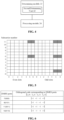
- FIG. 5 is a schematic diagram of time-frequency resources occupied by DMRS ⁇ 7,8,11,13 ⁇ ports in a physical resource block according to an embodiment of the present invention.
- Four DMRS ports occupy the same time-frequency resources by code division multiplexing.
- the DMRS port ⁇ 7,8,11,13 ⁇ occupies last two OFDM symbols of two slots in one subframe in time domain, and occupies subcarriers with sequence number ⁇ 11, 6, 1 ⁇ in the Physical Resource Block (PRB) in frequency domain.
- PRB Physical Resource Block
- the code division multiplexing is performed by the DMRS ports ⁇ 7,8,11,13 ⁇ on the four REs on the same subcarrier.
- FIG. 6 is orthogonal codes corresponding to the DMRS ⁇ 7,8,11,13 ⁇ ports.
- the receiving end obtains information on the range of the DMRS ports occupied by other MU-MIMO users (corresponding to the one or more second receiving ends) according to: enabling state of the joint encoding table, the number of layers corresponding to the PDSCH of the receiving end, the number of the codewords corresponding to the PDSCH of the receiving end and the DMRS ports of the receiving end.
- the joint encoding table 1 corresponds to, in a LTE Re12 version, a joint encoding table including the number of layers of the corresponding old 3 bits of the receiving ends, the DMRS ports of the receiving ends, and the scrambling code identification n scid of the DMRS of the receiving ends in a Downlink control information format 2C (DCI2C) and a Downlink control information format 2D (DCI2D), as shown in Table 1.
- DCI2C Downlink control information format 2C
- DCI2D Downlink control information format 2D
- the joint encoding table 2 corresponds to a joint encoding table including another number of layers, the DMRS ports, and the scrambling code identification n scid of the DMRS newly added in DCI2C, DCI2D, and other Downlink Control Information format (DCI) in a Rel-13 version, and an implementation of the joint encoding table 2 is shown in Table 2.
- the specific encoding mode of the joint encoding table 2 is only an example, but does not exclude other specific joint encoding modes.
- the joint encoding table 1 corresponds to the first DMRS port group
- the joint encoding table 2 corresponds to the third joint encoding table and the fourth joint encoding table.
- the correspondence relationship may be shown in Table 3, which is pre-determined by the transmitting end and the receiving end.
- the first DMRS port group can be configured for the joint encoding table 1 through RRC signaling
- the third DMRS port group and the fourth DMRS port group can be independently configured for the joint encoding table 2.
- Step 1 The first receiving end obtains the DMRS port group occupied by the one or more second receiving ends according to the currently-used joint encoding table, the number of layers corresponding to the PDSCH of the first receiving end, and the number of the codewords corresponding to the first receiving end.
- the DMRS port group occupied by the one or more second receiving ends is the first DMRS port group.
- the DMRS port group corresponding to the joint encoding table 1 described with reference to the Table 3 is a ⁇ 7,8 ⁇ port group.
- the DMRS port group occupied by the one or more second receiving ends is the first DMRS port group.
- the DMRS port group corresponding to the joint encoding table 1 described with reference to the Table 3 is the ⁇ 7,8 ⁇ port group.
- the DMRS port group occupied by the one or more second receiving ends is the third DMRS port group or the fourth DMRS port group.
- the third DMRS port group corresponding to the joint encoding table 2 described with reference to the Table 3 is the ⁇ 7,8 ⁇ port group
- the fourth DMRS port group corresponding to the joint encoding table 2 is a ⁇ 7,8,11,13 ⁇ port group.
- the number of the codewords corresponding to the PDSCH of the first receiving end is 2, the number of the layers corresponding to the PDSCH of the first receiving end is less than or equal to X22, and all DMRS ports of the first receiving end are a subset of the third DMRS port group or are a subset of the fourth DMRS port group, the DMRS port group occupied by the one or more second receiving ends is the third DMRS port group or the fourth DMRS port group.
- the third DMRS port group corresponding to the joint encoding table 2 described with reference to the Table 3 is the ⁇ 7,8 ⁇ port group
- the fourth DMRS port group corresponding to the joint encoding table 2 is the ⁇ 7,8,11,13 ⁇ port group.
- the DMRS port group occupied by the one or more second receiving ends is an empty set.
- X11 is the maximum number of layers which are possibly in an MU transmission mode in single codeword transmission in the joint encoding table 1
- X12 is the maximum number of layers which are possibly in the MU transmission mode in dual codewords transmission in the joint encoding table 1
- X21 is the maximum number of layers which are possibly in the MU transmission mode in the single codeword transmission in the joint encoding table 2
- X22 is the maximum number of layers which are possibly in the MU transmission mode in the dual codewords transmission in the joint encoding table 2.
- the joint encoding table 2 when the joint encoding table 2 is enabled (that is, the transmitting end indicates the first receiving end, and then according to the Table 2 and a value of a joint encoding domain, the number of layers of the PDSCH of the first receiving end, the DMRS ports of the first receiving end, and the scrambling code identification ID ( n scid ) of the DMRS ports of the first receiving end can be obtained), the number of the codewords of the first receiving end is 2, the joint encoding value is 0, the number of the layers is 2, and the DMRS ports of the first receiving end is ⁇ 7,8 ⁇ , so that the DMRS port group occupied by the one or more second receiving end is ⁇ 7,8 ⁇ or ⁇ 7,8,11,13 ⁇ .
- Step 2 The first receiving end determines the range of the DMRS port group occupied by the one or more second receiving ends according to the DMRS port group occupied by the one or more second receiving ends.
- the range of the DMRS ports occupied by the one or more second receiving ends includes one or two of the following cases.
- the ports in the DMRS port group which are different from the DMRS ports of the first receiving end are occupied, and in this case, the scrambling sequence of the ports occupied by the one or more second receiving ends and the scrambling sequence of the DMRS ports occupied by the first receiving end are the same, but the orthogonal codes of the ports occupied by the one or more second receiving ends and the orthogonal codes of the DMRS ports occupied by the first receiving end are different.
- the DMRS ports of the first receiving end are ⁇ 7,8 ⁇ , then the DMRS port group occupied by the one or more second receiving ends is ⁇ 7,8 ⁇ or ⁇ 7,8,11,13 ⁇ .
- the range of the DMRS ports occupied by the one or the second receiving ends includes one or two of the following cases.
- the DMRS port group ⁇ 7,8 ⁇ is abbreviated as a pseudo-orthogonal DMRS port group 1
- the DMRS port group ⁇ 7,8,11,13 ⁇ is abbreviated as a pseudo-orthogonal DMRS port group 2.
- the port ⁇ or ⁇ 11, 13 ⁇ is occupied by the one or more second receiving ends.
- the scrambling sequence of the ports occupied by the one or more second receiving ends and the scrambling sequence of the DMRS ports of the first receiving end are the same, but the orthogonal codes of the ports occupied by the one or more second receiving ends and the orthogonal codes of the DMRS ports of the first receiving end are different.
- the ⁇ ⁇ is abbreviated as the orthogonal DMRS port group 1
- the ⁇ 11, 13 ⁇ is abbreviated as the orthogonal DMRS port group 2.
- the range of the DMRS ports occupied by the one or more second receiving ends includes two DMRS port groups, that is, one of the pseudo-orthogonal DMRS port group 1 or the pseudo-orthogonal DMRS port group 2, and one of the orthogonal DMRS port group 1 or the orthogonal DMRS port group 2.
- Step 3 The first receiving end needs to assume that one or more second receiving ends may occupy part or all of the DMRS ports in one of the pseudo-orthogonal DMRS port group 1 and the pseudo-orthogonal DMRS port group 2.
- the first receiving end needs to further assume that there may be one or more second receiving ends occupying some or all of the DMRS ports in one of the orthogonal DMRS port group 1 and the orthogonal DMRS port group 2.
- the first receiving end needs to assume that the one or more second receiving ends may occupy some or all of the DMRS ports in the pseudo-orthogonal DMRS port group 1, and the first receiving end needs to further assume that the one or more second receiving ends may occupy some or all of the DMRS ports in the orthogonal DMRS port group 1.
- the Table 3 may be replaced with Table 4.
- the first DMRS port group corresponding to the joint encoding table 1 is ⁇ 7,8 ⁇ and the second DMRS port group corresponding to the joint encoding table 1 is ⁇ 7,8,11,13 ⁇
- the third DMRS port group corresponding to the joint encoding table 2 is ⁇ 7,8 ⁇
- the fourth DMRS port group corresponding to the joint encoding table 2 is ⁇ 7,8,11,13 ⁇ .
- the table 4 is pre-determined by the transmitting end and the receiving end.
- the first DMRS port group and second DMRS port group can be configured for the joint encoding table 1 through RRC signaling (corresponding to the fifth indication information and sixth indication information), respectively, and the third DMRS port group and the fourth DMRS port group can be configured independently for the joint encoding table 2.
- the first to fourth DMRS port groups may be the DMRS port groups different from ⁇ 7,8 ⁇ and ⁇ 7,8,11,13 ⁇ .
- the Table 3 may be replaced with Table 5.
- the first DMRS port group corresponding to the joint encoding table 1 is ⁇ 7,8 ⁇
- the fourth DMRS port group corresponding to the joint encoding table 2 is ⁇ 7,8 ⁇ .
- the table 4 is pre-determined by the transmitting end and the receiving end.
- the first DMRS port group can be configured for the joint encoding table 1 through RRC signaling (the fifth indication information and sixth indication information), respectively
- the third DMRS port group can be configured independently for the joint encoding table 2.
- the first DMRS port group and the third DMRS port group may be the DMRS port groups different from ⁇ 7,8 ⁇ and ⁇ 7,8,11,13 ⁇ .
- the first receiving end determines the DMRS port group occupied by the one or more second receiving ends according to the third indication information from the transmitting end, and the DMRS port group is one of the first DMRS port group and the second DMRS port group.
- the first receiving end determines the DMRS port group occupied by the one or more second receiving ends according to the fourth indication information from the transmitting end, and the DMRS port group is one of the third DMRS port group and the fourth DMRS port group.
- the first receiving end determines the range of the DMRS ports occupied by the one or more second receiving ends according to the usage state of the joint encoding table and the DMRS ports occupied by the first receiving end includes the following steps.
- the first receiving end determines the range of the DMRS ports occupied by the one or more second receiving ends according to the DMRS port group occupied by the one or more second receiving ends
- Step 1 The first receiving end obtains the DMRS port group occupied by the one or more second receiving ends according to the currently-used joint encoding table and the DMRS ports occupied by the first receiving end.
- the DMRS port group occupied by the one or more second receiving ends is the first DMRS port group ⁇ 7,8 ⁇ .
- the DMRS ports occupied by the first receiving end are a subset of the third DMRS port group ⁇ 7,8 ⁇ or are a subset of the fourth DMRS port group ⁇ 7,8,11,13 ⁇
- the DMRS port group occupied by one or more second receiving ends is the third DMRS port group or the fourth DMRS port group.
- the first DMRS port group and the third DMRS port group may be fixed to ⁇ 7,8 ⁇
- the fourth DMRS port group may be fixed to ⁇ 7,8,11,13 ⁇ .
- the first receiving end when the DMRS port group occupied by one or more second receiving ends is the first DMRS port group or the second DMRS port group, the first receiving end does not know the DMRS port group is which one of the two DMRS port groups, but only knows the DMRS port group is one of the two DMRS port groups. In this case, the first receiving end may determine, according to the third indication information from the transmitting end, that the DMRS port group occupied by the one or more second receiving ends is which one of the first DMRS port group and the second DMRS port group.
- the first receiving end does not know the DMRS port group is which one of the two DMRS port group, but only knows the DMRS port group is one of the two DMRS port groups. In this case, the first receiving end may determine, according to the fourth indication information from the transmitting end, that the DMRS port group occupied by the one or more second receiving ends is which one of the third DMRS port group and the fourth DMRS port group.
- Step 2 The first receiving end determines the range of the DMRS ports occupied by the one or more second receiving ends according to the DMRS port group occupied by the one or more second receiving ends.
- the range of the DMRS ports occupied by the one or more second receiving ends includes one or two of the following cases.
- the ports in the DMRS port group which are different from the DMRS ports of the first receiving end are occupied, and in this case, the scrambling sequence of the ports occupied by the one or more second receiving ends and the scrambling sequence of the DMRS ports occupied by the first receiving end are the same, but the orthogonal codes of the ports occupied by the one or more second receiving ends and the orthogonal codes of the DMRS ports occupied by the first receiving end are different.
- the DMRS ports of the first receiving end are ⁇ 7,8 ⁇
- the DMRS port group occupied by one or more second receiving end is ⁇ 7,8 ⁇ or ⁇ 7,8,11,13 ⁇ .
- the range of the DMRS ports occupied by the one or the second receiving ends includes one or two of the following cases.
- the DMRS port group ⁇ 7,8 ⁇ is abbreviated as a pseudo-orthogonal DMRS port group 1
- the DMRS port group ⁇ 7,8,11,13 ⁇ is abbreviated as a pseudo-orthogonal DMRS port group 2.
- the port group occupied by the one or more second receiving ends is ⁇ or ⁇ 11, 13 ⁇ .
- the scrambling sequence of the ports occupied by the one or more second receiving ends and the scrambling sequence of the DMRS ports of the first receiving end are the same, but the orthogonal codes of the ports occupied by the one or more second receiving ends and the orthogonal codes of the DMRS ports of the first receiving end are different.
- the ⁇ is abbreviated as the orthogonal DMRS port group 1
- the ⁇ 11, 13 ⁇ is abbreviated as the orthogonal DMRS port group 2.
- the range of the DMRS ports occupied by the one or more second receiving ends includes two DMRS port groups, that is, one of the pseudo-orthogonal DMRS port group 1 or the pseudo-orthogonal DMRS port group 2 and one of the orthogonal DMRS port group 1 or the orthogonal DMRS port group 2.
- Step 3 The first receiving end needs to assume that one or more second receiving ends may occupy part or all of the DMRS ports in one of the pseudo-orthogonal DMRS port group 1 and the pseudo-orthogonal DMRS port group 2.
- the first receiving end needs to further assume that there may be one or more second receiving ends occupying some or all of the DMRS ports in one of the orthogonal DMRS port group 1 and orthogonal DMRS port group 2.
- the first receiving end needs to assume that the one or more second receiving ends may occupy some or all of the DMRS ports in the pseudo-orthogonal DMRS port group 1, and the first receiving end needs to further assume that the one or more second receiving ends may occupy some or all of the DMRS ports in the orthogonal DMRS port group 1.
- the above modules can be implemented by software or hardware, and the latter can be implemented in the following manner that the above modules are all located in the same processor, or the above modules are respectively located in multiple processors, but the present invention is not limited to thereto.
- the embodiments of the present invention also provide a storage medium.
- the storage medium can be set to store program code for executing the following steps.
- the first receiving end determines a range of data demodulation reference signal DMRS ports occupied by one or more second receiving ends by using at least one of the following information: a usage state of a joint encoding table corresponding to a DMRS port group, the number of layers corresponding to a physical downlink shared channel (PDSCH) of the first receiving end, and the number of codewords corresponding to the PDSCH of the first receiving end.
- a usage state of a joint encoding table corresponding to a DMRS port group the number of layers corresponding to a physical downlink shared channel (PDSCH) of the first receiving end
- PDSCH physical downlink shared channel
- the first receiving end processes data according to the range of the DMRS ports occupied by the one or more second receiving ends.
- the above storage medium may include, but is not limited to, various storage medium for storing program code, such as a U disk, a Read-Only Memory (ROM), a Random Access Memory (RAM), a removable hard disk, a magnetic disk, a disc or optical disc.
- program code such as a U disk, a Read-Only Memory (ROM), a Random Access Memory (RAM), a removable hard disk, a magnetic disk, a disc or optical disc.
- the processor executes the foregoing steps S1 - S2 according to the program code stored in the storage medium.
- the effects of reducing the complexity of the blind detection of the OCC length of the receiving end and improving the channel estimation performance of the receiving end and the demodulation reception performance of the receiving end are achieved, while effectively saving the DCI overhead.
- modules or steps of the present application can be implemented by a general-purpose computing device, which may be concentrated on a single computing device or distributed over a network of multiple computing devices. Alternatively, they may be implemented with program code that is executable by the computing device so that they may be stored in a storage device and executed by a computing device, and in some cases, the steps shown or described may be performed in a different order other than this, or they may be separately made into individual integrated circuit modules, or multiple modules or steps in them are made into a single integrated circuit module. Thus, the present application is not limited to any specific combination of hardware and software.
- An embodiment of the present invention provides a data processing method and apparatus, so as to at least solve the problems in the prior art that blind detection of the OCC length is complex, channel estimation performance of the receiving end is low, and demodulation reception performance of the receiving end is low due to the case that the receiving end cannot confirm DMRS port occupation situations of other receiving ends.
- the method includes: a first receiving end determines a range of data demodulation reference signal (DMRS) ports occupied by one or more second receiving ends by using at least one of the following information: a usage state of a joint encoding table corresponding to a DMRS port group, the number of layers corresponding to a physical downlink shared channel (PDSCH) of the first receiving end, and the number of codewords corresponding to the PDSCH of the first receiving end; and the first receiving end processes data according to the range of the DMRS ports occupied by the one or more second receiving ends.
- DMRS data demodulation reference signal
Landscapes
- Engineering & Computer Science (AREA)
- Signal Processing (AREA)
- Computer Networks & Wireless Communication (AREA)
- Power Engineering (AREA)
- Quality & Reliability (AREA)
- Mobile Radio Communication Systems (AREA)
Claims (15)
- Procédé de traitement de données, comprenant :la détermination (S102), par un premier terminal, d'une plage de ports de signal de référence de démodulation de données, DMRS, occupés par au moins un deuxième terminal conformément à une table de codage conjointe sélectionnée parmi plusieurs tables de codage conjointes, et d'un nombre de mots de code correspondant à un canal physique partagé de liaison descendante, PDSCH, du premier terminal ; etle traitement (S104), par le premier terminal, de données du premier terminal en fonction de la plage de ports DMRS occupés par ledit au moins un deuxième terminal ;où ledit au moins un deuxième terminal et le premier terminal sont des terminaux entrées multiples/sorties multiples multiutilisateurs, MU-MIMO, chacune des multiples tables de codage conjointes correspondant à un ou plusieurs groupes DMRS comprenant les ports DMRS occupés par ledit au moins un deuxième terminal, chacune des multiples tables conjointes étant une table comprenant une correspondance entre une valeur indiquée par une information de commande de liaison descendante, DCI, et le nombre de couches correspondant au PDSCH du premier terminal, et un port DMRS du PDSCH du premier terminal.
- Procédé selon la revendication 1, où
la détermination, par le premier terminal, de la plage du groupe de ports DMRS occupés par ledit au moins un deuxième terminal comprend :
la détermination, par le premier terminal, de la plage des ports DMRS occupés par ledit au moins un deuxième terminal en fonction des ports DMRS occupés par ledit au moins un deuxième terminal, où,
si la table de codage conjointe sélectionnée est :une table de codage conjointe 1 utilisée par le premier terminal, le nombre de mots de code correspondant au PDSCH du premier terminal est 1, et le nombre de couches correspondant au PDSCH du premier terminal est inférieur ou égal à X11, le groupe de ports DMRS occupés par ledit au moins un deuxième terminal est soit le premier groupe de ports DMRS, soit le deuxième groupe de ports DMRS ;une table de codage conjointe 1 utilisée par le premier terminal, le nombre de mots de code correspondant au PDSCH du premier terminal est de 2, et le nombre de couches correspondant au PDSCH du premier terminal est inférieur ou égal à X12, le groupe de ports DMRS occupés par ledit au moins un deuxième terminal est soit le premier groupe de ports DMRS, soit le deuxième groupe de ports DMRS ;une table de codage conjointe 2 utilisée par le premier terminal, le nombre de mots de code correspondant au PDSCH du premier terminal est 1, et le nombre de couches correspondant au PDSCH du premier terminal est inférieur ou égal à X21, le groupe de ports DMRS occupés par ledit au moins un deuxième terminal est soit un troisième groupe de ports DMRS, soit un quatrième groupe de ports DMRS ;une table de codage conjointe 2 utilisée par le premier terminal, le nombre de mots codés correspondant au PDSCH du premier terminal est de 2, le nombre de couches correspondant au PDSCH du premier terminal est inférieur ou égal à X22, et tous les ports DMRS du premier terminal sont un sous-ensemble du troisième groupe de ports DMRS et sont un sous-ensemble du quatrième groupe de ports DMRS, le groupe de ports DMRS occupés par ledit au moins un deuxième terminal est soit le troisième groupe de ports DMRS, soit le quatrième groupe de ports DMRS ;dans les autres cas, le groupe de ports DMRS occupés par ledit au moins un deuxième terminal est un ensemble vide ;où X11, X12, X21 et X22 sont tous des entiers positifs ; X11, X12, le premier groupe de ports DMRS et le deuxième groupe de ports DMRS sont tous déterminés conformément à la table de codage conjointe 1, et X21, X22, le troisième groupe de ports DMRS et le quatrième groupe de ports DMRS sont tous déterminés selon la table de codage conjointe 2 ; et où la table de codage conjointe 1 et la table de codage conjointe 2 sont deux tables de codage conjointes différentes, et la table de codage conjointe est une table comprenant au moins deux des éléments suivants : le nombre de couches correspondant au PDSCH du premier terminal, un port DMRS occupé par le premier terminal, et une identification nscid de code de brouillage du port DMRS occupé par le premier terminal, et où une table actuellement utilisée est déterminée par le premier terminal conformément à une première information d'indication provenant de l'extrémité de transmission,où la table de codage conjointe 1 est définie comme suit :Un seul mot de code : Deux mots de code : Mot de code 0 activé, Mot de code 0 activé, Mot de code 1 désactivé Mot de code 1 activé Valeur Message Valeur Message 0 1 couche, port 7, nSCID=0 0 2 couches, ports 7-8, nSCID=0 1 1 couche, port 7, nSCID=1 1 2 couches, ports 7-8, nSCID=1 2 1 couche, port 8, nSCID=0 2 3 couches, ports 7-9 3 1 couche, port 8, nSCID=1 3 4 couches, ports 7-10 4 2 couches, ports 7-8 4 5 couches, ports 7-11 5 3 couches, ports 7-9 5 6 couches, ports 7-12 6 4 couches, ports 7-10 6 7 couches, ports 7-13 7 Réservé 7 8 couches, ports 7-14 la table de codage conjointe 2 est définie comme suit :Un seul mot de code : Deux mots de code : Mot de code 0 activé, Mot de code 0 activé, Mot de code 1 désactivé Mot de code 1 activé Valeur Message Valeur Message 0 1 couche, port 7, nSCID=0 0 2 couches, ports 7∼8, nSCID=0 1 1 couche, port 7, nSCID=1 1 2 couches, ports7∼8, nSCID=1 2 1 couche, port 8, nSCID=0 2 3 couches, ports 7-9 3 1 couche, port 8, nSCID=1 3 4 couches, ports 7-10 4 2 couches, ports 7-8 4 5 couches, ports 7-11 5 3 couches, ports 7-9 5 6 couches, ports 7-12 6 1 couche, port 11, nSCID=0 6 2 couches, ports {11,13}, nSCID=0 7 1 couche, port 13, nSCID=0 7 2 couches, ports {11,13}, nSCID=1 - Procédé selon la revendication 1, où
la détermination, par le premier terminal, de la plage des ports DMRS occupés par ledit au moins un deuxième terminal en fonction de l'état d'utilisation de la table de codage conjointe et du port DMRS occupé par le premier terminal. - Procédé selon la revendication 3, où
la détermination, par le premier terminal, de la plage des ports DMRS occupés par ledit au moins un deuxième terminal en fonction de l'état d'utilisation de la table de codage conjointe et du port DMRS occupé par le premier terminal comprend :
la détermination, par le premier terminal, de la plage des ports DMRS occupés par ledit au moins un deuxième terminal en fonction du groupe de ports DMRS occupés par ledit au moins un deuxième terminal, où,
si la table de codage conjointe sélectionnée est :une table de codage conjointe 1 utilisée par le premier terminal, et le port DMRS occupé par le premier terminal est un sous-ensemble d'un premier groupe de ports DMRS ou est un sous-ensemble d'un deuxième groupe de ports DMRS, le groupe de ports DMRS occupés par ledit au moins un deuxième terminal est soit le premier groupe de ports DMRS, soit le deuxième groupe de ports DMRS ;une table de codage conjointe 2 utilisée par le premier terminal, et le port DMRS occupé par le premier terminal est un sous-ensemble d'un troisième groupe de ports DMRS ou est un sous-ensemble d'un quatrième groupe de ports DMRS, le groupe de ports DMRS occupés par ledit au moins un deuxième terminal est soit le troisième groupe de ports DMRS, soit le quatrième groupe de ports DMRS ;où le premier groupe de ports DMRS et le deuxième groupe de ports DMRS sont déterminés conformément à la table de codage conj ointe 1, et le troisième groupe de ports DMRS et le quatrième groupe de ports DMRS sont déterminés conformément à la table de codage conjointe 2 ; où la table de codage conjointe 1 et la table de codage conjointe 2 sont deux tables de codage conjointes différentes, et la table de codage conjointe est une table comprenant au moins deux des éléments suivants : le nombre de couches correspondant au PDSCH du premier terminal, le port DMRS occupé par le premier terminal, et une identification nscid de code de brouillage DMRS du port DMRS occupé par le premier terminal, et où une table actuellement utilisée est déterminée par le premier terminal conformément à une deuxième information d'indication provenant de l'extrémité de transmission,où la table de codage conjointe 1 est définie comme suit :Un seul mot de code : Deux mots de code : Mot de code 0 activé, Mot de code 0 activé, Mot de code 1 désactivé Mot de code 1 activé Valeur Message Valeur Message 0 1 couche, port 7, nSCID=0 0 2 couches, ports 7-8, nSCID=0 1 1 couche, port 7, nSCID=1 1 2 couches, ports 7-8, nSCID=1 2 1 couche, port 8, nSCID=0 2 3 couches, ports 7-9 3 1 couche, port 8, nSCID=1 3 4 couches, ports 7-10 4 2 couches, ports 7-8 4 5 couches, ports 7-11 5 3 couches, ports 7-9 5 6 couches, ports 7-12 6 4 couches, ports 7-10 6 7 couches, ports 7-13 7 Réservé 7 8 couches, ports 7-14 la table de codage conjointe 2 est définie comme suit :Un seul mot de code : Deux mots de code : Mot de code 0 activé, Mot de code 0 activé, Mot de code 1 désactivé Mot de code 1 activé Valeur Message Valeur Message 0 1 couche, port 7, nSCID=0 0 2 couches, ports 7∼8, nSCID=0 1 1 couche, port 7, nSCID=1 1 2 couches, ports7∼8, nSCID=1 2 1 couche, port 8, nSCID=0 2 3 couches, ports 7-9 3 1 couche, port 8, nSCID=1 3 4 couches, ports 7-10 4 2 couches, ports 7-8 4 5 couches, ports 7-11 5 3 couches, ports 7-9 5 6 couches, ports 7-12 6 1 couche, port 11, nSCID=0 6 2 couches, ports {11,13}, nSCID=0 7 1 couche, port 13, nSCID=0 7 2 couches, ports {11,13}, nSCID=1 - Procédé selon l'une des revendications 2 à 4, où,si le groupe de ports DMRS occupés par ledit au moins un deuxième terminal est soit le premier groupe de ports DMRS, soit le deuxième groupe de ports DMRS, le groupe de ports DMRS occupés par ledit au moins un deuxième terminal est déterminé par le premier terminal conformément à une troisième information d'indication provenant de l'extrémité de transmission ; et/ou,si le groupe de ports DMRS occupés par ledit au moins un deuxième terminal est soit le troisième groupe de ports DMRS, soit le quatrième groupe de ports DMRS, le groupe de ports DMRS occupés par ledit au moins un deuxième terminal est déterminé par le premier terminal conformément à la quatrième information d'indication provenant de l'extrémité de transmission.
- Procédé selon la revendication 2 ou la revendication 4, comprenant en outre au moins l'une des configurations suivantes :configuration du premier groupe de ports DMRS et du deuxième groupe de ports DMRS correspondant à la table de codage conjointe 1 conformément à la cinquième information d'indication provenant de l'extrémité de transmission ; ou,configuration du troisième groupe de ports DMRS et du quatrième groupe de ports DMRS correspondant à la table de codage conjointe 2 conformément à la sixième information d'indication provenant de l'extrémité de transmission.
- Procédé selon la revendication 2 ou la revendication 4, où
la détermination, par le premier terminal, de la plage des ports DMRS occupés par ledit au moins un deuxième terminal en fonction du groupe de ports DMRS occupés par ledit au moins un deuxième terminal, comprend au moins l'une des déterminations suivantes :détermination que tous les ports du groupe de ports DMRS occupés par ledit au moins un deuxième terminal sont la plage des ports DMRS occupés par ledit au moins un deuxième terminal, les paramètres d'initialisation d'une séquence de brouillage des ports DMRS occupés par ledit au moins un deuxième terminal et les paramètres d'initialisation d'une séquence de brouillage du port DMRS occupé par le premier terminal remplissant les conditions suivantes : n scid,2 = 1 - n scid,1,


oudétermination que des ports du groupe de ports DMRS occupés par ledit au moins un deuxième terminal et différents du port DMRS occupé par le premier terminal sont la plage des ports DMRS occupés par ledit au moins un deuxième terminal, la séquence de brouillage des ports DMRS occupés par ledit au moins un deuxième terminal et la séquence de brouillage du port DMRS occupé par le premier terminal étant identiques, les codes orthogonaux des ports DMRS occupés par ledit au moins un deuxième terminal et les codes orthogonaux du port DMRS occupé par le premier terminal étant toutefois différents. - Dispositif de traitement de données appliqué à un premier terminal, comprenant :un module de détermination (22), configuré pour déterminer une plage de ports DMRS occupés par au moins un deuxième terminal conformément à une table de codage conjointe sélectionnée parmi plusieurs tables de codage conjointes, et un nombre de mots de code correspondant à un canal physique partagé de liaison descendante, PDSCH, du premier terminal ; etun module de traitement (24), configuré pour traiter les données du premier terminal en fonction de la plage des ports DMRS occupés par ledit au moins un deuxième terminal ;où ledit au moins un deuxième terminal et le premier terminal sont des terminaux MU-MIMO,où chacune des multiples tables de codage conjointes correspond à un ou plusieurs groupes DMRS comprenant les ports DMRS occupés par ledit au moins un deuxième terminal, chacune des multiples tables conjointes étant une table comprenant une correspondance entre une valeur indiquée par une information de commande de liaison descendante, DCI, et le nombre de couches correspondant au PDSCH du premier terminal, et un port DMRS du PDSCH du premier terminal.
- Dispositif selon la revendication 8, où
le module de détermination (22) comprend :
une première unité de détermination (32), configurée pour déterminer la plage des ports DMRS occupés par ledit au moins un deuxième terminal en fonction des ports DMRS occupés par ledit au moins un deuxième terminal, où,
si la table de codage conjointe sélectionnée est :une table de codage conjointe 1 utilisée par le premier terminal, le nombre de mots de code correspondant au PDSCH du premier terminal est 1, et le nombre de couches correspondant au PDSCH du premier terminal est inférieur ou égal à X11, le groupe de ports DMRS occupés par ledit au moins un deuxième terminal est soit un premier groupe de ports DMRS, soit un deuxième groupe de ports DMRS ;une table de codage conjointe 1 utilisée par le premier terminal, le nombre de mots de code correspondant au PDSCH du premier terminal est 2, et le nombre de couches correspondant au PDSCH du premier terminal est inférieur ou égal à X12, le groupe de ports DMRS occupés par ledit au moins un deuxième terminal est soit le premier groupe de ports DMRS, soit le deuxième groupe de ports DMRS ;une table de codage conjointe 2 utilisée par le premier terminal, le nombre de mots de code correspondant au PDSCH du premier terminal est 1, et le nombre de couches correspondant au PDSCH du premier terminal est inférieur ou égal à X21, le groupe de ports DMRS occupés par ledit au moins un deuxième terminal est soit un troisième groupe de ports DMRS, soit un quatrième groupe de ports DMRS ;une table de codage conjointe 2 utilisée par le premier terminal, le nombre de mots de code correspondant au PDSCH du premier terminal est 2, le nombre de couches correspondant au PDSCH du premier terminal est inférieur ou égal à X22, et tous les ports DMRS du premier terminal sont un sous-ensemble du troisième groupe de ports DMRS ou un sous-ensemble du quatrième groupe de ports DMRS, le groupe de ports DMRS occupés par ledit au moins un deuxième terminal est soit le troisième groupe de ports DMRS, soit le quatrième groupe de ports DMRS ;dans les autres cas, le groupe de ports DMRS occupés par ledit au moins un deuxième terminal est un ensemble vide ;où X11, X12, X21 et X22 sont tous des entiers positifs ; X11, X12, le premier groupe de ports DMRS et le deuxième groupe de ports DMRS sont tous déterminés conformément à la table de codage conjointe 1, et X21, X22, le troisième groupe de ports DMRS et le quatrième groupe de ports DMRS sont tous déterminés selon la table de codage conjointe 2 ; et où la table de codage conjointe 1 et la table de codage conjointe 2 sont deux tables de codage conjointes différentes, et la table de codage conjointe est une table comprenant au moins deux des éléments suivants : le nombre de couches correspondant au PDSCH du premier terminal, un port DMRS occupé par le premier terminal, et une identification nscid de code de brouillage DMRS du port DMRS occupé par le premier terminal, et une table actuellement utilisée est déterminée par le premier terminal conformément à une première information d'indication provenant de l'extrémité de transmission,où la table de codage conjointe 1 est définie comme suit :Un seul mot de code : Deux mots de code : Mot de code 0 activé, Mot de code 0 activé, Mot de code 1 désactivé Mot de code 1 activé Valeur Message Valeur Message 0 1 couche, port 7, nSCID=0 0 2 couches, ports 7-8, nSCID=0 1 1 couche, port 7, nSCID=1 1 2 couches, ports 7-8, nSCID=1 2 1 couche, port 8, nSCID=0 2 3 couches, ports 7-9 3 1 couche, port 8, nSCID=1 3 4 couches, ports 7-10 4 2 couches, ports 7-8 4 5 couches, ports 7-11 5 3 couches, ports 7-9 5 6 couches, ports 7-12 6 4 couches, ports 7-10 6 7 couches, ports 7-13 7 Réservé 7 8 couches, ports 7-14 la table de codage conjointe 2 est définie comme suit :Un seul mot de code : Deux mots de code : Mot de code 0 activé, Mot de code 0 activé, Mot de code 1 désactivé Mot de code 1 activé Valeur Message Valeur Message 0 1 couche, port 7, nSCID=0 0 2 couches, ports 7∼8, nSCID=0 1 1 couche, port 7, nSCID=1 1 2 couches, ports7∼8, nSCID=1 2 1 couche, port 8, nSCID=0 2 3 couches, ports 7-9 3 1 couche, port 8, nSCID=1 3 4 couches, ports 7-10 4 2 couches, ports 7-8 4 5 couches, ports 7-11 5 3 couches, ports 7-9 5 6 couches, ports 7-12 6 1 couche, port 11, nSCID=0 6 2 couches, ports {11,13}, nSCID=0 7 1 couche, port 13, nSCID=0 7 2 couches, ports {11,13}, nSCID=1 - Dispositif selon la revendication 8, où
une deuxième unité de détermination (42), configurée pour déterminer la plage des ports DMRS occupés par ledit au moins un deuxième terminal en fonction de l'état d'utilisation de la table de codage conjointe et du port DMRS occupé par le premier terminal. - Dispositif selon la revendication 10, où la deuxième unité de détermination (42) est configurée pour déterminer la plage des ports DMRS occupés par ledit au moins un deuxième terminal de la manière suivante :
détermination de la plage des ports DMRS occupés par ledit au moins un deuxième terminal en fonction du groupe de ports DMRS occupés par ledit au moins un deuxième terminal, où,
si la table de codage conjointe sélectionnée est :une table de codage conjointe 1 utilisée par le premier terminal, et le port DMRS occupé par le premier terminal est un sous-ensemble d'un premier groupe de ports DMRS ou est un sous-ensemble d'un deuxième groupe de ports DMRS, le groupe de ports DMRS occupés par ledit au moins un deuxième terminal est soit le premier groupe de ports DMRS, soit le deuxième groupe de ports DMRS ;une table de codage conjointe 2 utilisée par le premier terminal, et le port DMRS occupé par le premier terminal est un sous-ensemble d'un troisième groupe de ports DMRS ou est un sous-ensemble d'un quatrième groupe de ports DMRS, le groupe de ports DMRS occupés par ledit au moins un deuxième terminal est soit le troisième groupe de ports DMRS, soit le quatrième groupe de ports DMRS ;le premier groupe de ports DMRS et le deuxième groupe de ports DMRS étant déterminés conformément à la table de codage conjointe 1, et le troisième groupe de ports DMRS et le quatrième groupe de ports DMRS étant déterminés conformément à la table de codage conjointe 2 ; la table de codage conjointe 1 et la table de codage conjointe 2 étant deux tables de codage conjointes différentes, et la table de codage conjointe étant une table comprenant au moins deux des éléments suivants : le nombre de couches correspondant au PDSCH du premier terminal, le port DMRS occupé par le premier terminal, et une identification nscid de code de brouillage DMRS du port DMRS occupé par le premier terminal, et où une table actuellement utilisée est déterminée par le premier terminal conformément à la deuxième information d'indication provenant de l'extrémité d'émission,où la table de codage conjointe 1 est définie comme suit :Un seul mot de code : Deux mots de code : Mot de code 0 activé, Mot de code 0 activé, Mot de code 1 désactivé Mot de code 1 activé Valeur Message Valeur Message 0 1 couche, port 7, nSCID=0 0 2 couches, ports 7-8, nSCID=0 1 1 couche, port 7, nSCID=1 1 2 couches, ports 7-8, nSCID=1 2 1 couche, port 8, nSCID=0 2 3 couches, ports 7-9 3 1 couche, port 8, nSCID=1 3 4 couches, ports 7-10 4 2 couches, ports 7-8 4 5 couches, ports 7-11 5 3 couches, ports 7-9 5 6 couches, ports 7-12 6 4 couches, ports 7-10 6 7 couches, ports 7-13 7 Réservé 7 8 couches, ports 7-14 la table de codage conjointe 2 est définie comme suit :Un seul mot de code : Deux mots de code : Mot de code 0 activé, Mot de code 0 activé, Mot de code 1 désactivé Mot de code 1 activé Valeur Message Valeur Message 0 1 couche, port 7, nSCID=0 0 2 couches, ports 7∼8, nSCID=0 1 1 couche, port 7, nSCID=1 1 2 couches, ports7∼8, nSCID=1 2 1 couche, port 8, nSCID=0 2 3 couches, ports 7-9 3 1 couche, port 8, nSCID=1 3 4 couches, ports 7-10 4 2 couches, ports 7-8 4 5 couches, ports 7-11 5 3 couches, ports 7-9 5 6 couches, ports 7-12 6 1 couche, port 11, nSCID=0 6 2 couches, ports {11,13}, nSCID=0 7 1 couche, port 13, nSCID=0 7 2 couches, ports {11,13}, nSCID=1 - Dispositif selon l'une des revendications 9 à 11, où,si le groupe de ports DMRS occupés par ledit au moins un deuxième terminal est soit le premier groupe de ports DMRS, soit le deuxième groupe de ports DMRS, le premier terminal détermine le groupe de ports DMRS occupés par ledit au moins un deuxième terminal conformément à la troisième information d'indication provenant de l'extrémité de transmission ; et,si le groupe de ports DMRS occupés par ledit au moins un deuxième terminal est soit le troisième groupe de ports DMRS, soit le quatrième groupe de ports DMRS, le premier terminal détermine le groupe de ports DMRS occupés par ledit au moins un deuxième terminal conformément à la quatrième information d'indication provenant de l'extrémité de transmission.
- Dispositif selon la revendication 9 ou la revendication 11, oùle premier groupe de ports DMRS et le deuxième groupe de ports DMRS correspondant à la table de codage conjointe 1 sont configurés conformément à la cinquième information d'indication provenant de l'extrémité de transmission ; et/ou,le troisième groupe de ports DMRS et le quatrième groupe de ports DMRS correspondant à la table de codage conjointe 2 sont configurés conformément à la sixième information d'indication provenant de l'extrémité de transmission.
- Dispositif selon la revendication 9 ou la revendication 11, où
la première unité de détermination (32) et la deuxième unité de détermination (42), dans lesquelles le premier terminal détermine la plage des ports DMRS occupés par ledit au moins un deuxième terminal en fonction du groupe de ports DMRS occupés par ledit au moins un deuxième terminal, sont en outre configurées chacune pour au moins une des déterminations suivantes :détermination que tous les ports du groupe de ports DMRS occupés par ledit au moins un deuxième terminal sont la plage des ports DMRS occupés par ledit au moins un deuxième terminal, les paramètres d'initialisation d'une séquence de brouillage des ports DMRS occupés par ledit au moins un deuxième terminal et les paramètres d'initialisation d'une séquence de brouillage du port DMRS occupé par le premier terminal remplissant les conditions suivantes : n scid,2 = 1 - n scid,1,


oudétermination que des ports du groupe de ports DMRS occupés par ledit au moins un deuxième terminal et différents du port DMRS occupé par le premier terminal sont la plage des ports DMRS occupés par ledit au moins un deuxième terminal, la séquence de brouillage des ports DMRS occupés par ledit au moins un deuxième terminal et la séquence de brouillage du port DMRS occupé par le premier terminal étant identiques, les codes orthogonaux des ports DMRS occupés par ledit au moins un deuxième terminal et les codes orthogonaux du port DMRS occupé par le premier terminal étant toutefois différents. - Support d'enregistrement lisible par ordinateur comprenant des instructions dont l'exécution par un ordinateur entraîne ledit ordinateur à mettre en oeuvre les étapes suivantes :détermination d'une plage de ports DMRS occupés par au moins un deuxième terminal conformément à une table de codage conjointe sélectionnée parmi plusieurs tables de codage conjointes, et d'un nombre de mots de code correspondant à un canal physique partagé de liaison descendante, PDSCH, du premier terminal ; ettraitement des données du premier terminal en fonction de la plage des ports DMRS occupés par ledit au moins un deuxième terminal ;où ledit au moins un deuxième terminal et le premier terminal sont des terminaux MU-MIMO, etoù chacune des multiples tables de codage conjointes correspond à un ou plusieurs groupes DMRS comprenant les ports DMRS occupés par ledit au moins un deuxième terminal, chacune des multiples tables conjointes étant une table comprenant une correspondance entre une valeur indiquée par une DCI et le nombre de couches correspondant au PDSCH du premier terminal, et un port DMRS du PDSCH du premier terminal.
Applications Claiming Priority (2)
| Application Number | Priority Date | Filing Date | Title |
|---|---|---|---|
| CN201510752412.5A CN106685580B (zh) | 2015-11-06 | 2015-11-06 | 数据处理方法及装置 |
| PCT/CN2016/095726 WO2017076102A1 (fr) | 2015-11-06 | 2016-08-17 | Procédé et appareil de traitement de données |
Publications (3)
| Publication Number | Publication Date |
|---|---|
| EP3373674A1 EP3373674A1 (fr) | 2018-09-12 |
| EP3373674A4 EP3373674A4 (fr) | 2019-07-10 |
| EP3373674B1 true EP3373674B1 (fr) | 2024-11-06 |
Family
ID=58661522
Family Applications (1)
| Application Number | Title | Priority Date | Filing Date |
|---|---|---|---|
| EP16861371.9A Active EP3373674B1 (fr) | 2015-11-06 | 2016-08-17 | Procédé et appareil de traitement de données |
Country Status (6)
| Country | Link |
|---|---|
| US (1) | US10784938B2 (fr) |
| EP (1) | EP3373674B1 (fr) |
| CN (1) | CN106685580B (fr) |
| ES (1) | ES2992804T3 (fr) |
| FI (1) | FI3373674T3 (fr) |
| WO (1) | WO2017076102A1 (fr) |
Families Citing this family (5)
| Publication number | Priority date | Publication date | Assignee | Title |
|---|---|---|---|---|
| US10419181B2 (en) | 2017-03-31 | 2019-09-17 | Futurewei Technologies, Inc. | System and method for demodulation reference signal overhead reduction |
| WO2018184169A1 (fr) | 2017-04-06 | 2018-10-11 | Qualcomm Incorporated | Indication de chargement de port d'utilisateur multiple |
| CN109391413B (zh) * | 2017-08-10 | 2022-05-10 | 华为技术有限公司 | 信息传输的方法和通信装置 |
| CN109391571B (zh) * | 2017-08-11 | 2020-12-04 | 华为技术有限公司 | 相位噪声估计方法及设备 |
| CN110855330B (zh) * | 2018-08-20 | 2022-05-03 | 大唐移动通信设备有限公司 | 一种传输方法及装置 |
Citations (1)
| Publication number | Priority date | Publication date | Assignee | Title |
|---|---|---|---|---|
| US20150263796A1 (en) * | 2014-03-14 | 2015-09-17 | Samsung Electronics Co., Ltd. | Channel state information for reporting an advanced wireless communications system |
Family Cites Families (10)
| Publication number | Priority date | Publication date | Assignee | Title |
|---|---|---|---|---|
| WO2011011566A2 (fr) * | 2009-07-24 | 2011-01-27 | Interdigital Patent Holdings, Inc. | Procédé et dispositif permettant dobtenir des informations dindex de port de signal de référence de démodulation |
| CN102122984B (zh) * | 2010-01-11 | 2015-07-15 | 株式会社Ntt都科摩 | 多用户多输入多输出mu-mimo传输方法、无线通信系统以及基站 |
| CN102340463B (zh) * | 2010-07-26 | 2014-07-30 | 华为技术有限公司 | 一种信道估计方法、装置和系统 |
| KR101577518B1 (ko) * | 2011-06-22 | 2015-12-14 | 엘지전자 주식회사 | 무선 통신 시스템에서 참조 신호 포트를 할당하는 방법 및 장치 |
| WO2013002544A2 (fr) * | 2011-06-27 | 2013-01-03 | 엘지전자 주식회사 | Procédé et dispositif pour attribution de canal de commande de liaison descendante dans un système de communication sans fil |
| US9019924B2 (en) * | 2012-04-04 | 2015-04-28 | Samsung Electronics Co., Ltd. | High-order multiple-user multiple-input multiple-output operation for wireless communication systems |
| CN103581869B (zh) | 2012-08-03 | 2018-11-09 | 中兴通讯股份有限公司 | 控制信息处理方法及装置 |
| CN103684676B (zh) * | 2012-09-26 | 2018-05-15 | 中兴通讯股份有限公司 | 天线端口位置关系的通知和确定方法、系统及装置 |
| CN103841644B (zh) * | 2012-11-22 | 2018-04-17 | 电信科学技术研究院 | 一种传输解调参考信号的方法、设备及系统 |
| US10367551B2 (en) * | 2015-01-29 | 2019-07-30 | Intel Corporation | Precoding resource block group bundling enhancement for full dimension multi-in-multi-output |
-
2015
- 2015-11-06 CN CN201510752412.5A patent/CN106685580B/zh active Active
-
2016
- 2016-08-17 EP EP16861371.9A patent/EP3373674B1/fr active Active
- 2016-08-17 US US15/774,088 patent/US10784938B2/en active Active
- 2016-08-17 FI FIEP16861371.9T patent/FI3373674T3/fi active
- 2016-08-17 WO PCT/CN2016/095726 patent/WO2017076102A1/fr not_active Ceased
- 2016-08-17 ES ES16861371T patent/ES2992804T3/es active Active
Patent Citations (1)
| Publication number | Priority date | Publication date | Assignee | Title |
|---|---|---|---|---|
| US20150263796A1 (en) * | 2014-03-14 | 2015-09-17 | Samsung Electronics Co., Ltd. | Channel state information for reporting an advanced wireless communications system |
Also Published As
| Publication number | Publication date |
|---|---|
| CN106685580B (zh) | 2020-03-03 |
| EP3373674A4 (fr) | 2019-07-10 |
| EP3373674A1 (fr) | 2018-09-12 |
| ES2992804T3 (en) | 2024-12-18 |
| FI3373674T3 (fi) | 2025-01-22 |
| US10784938B2 (en) | 2020-09-22 |
| CN106685580A (zh) | 2017-05-17 |
| US20180316406A1 (en) | 2018-11-01 |
| WO2017076102A1 (fr) | 2017-05-11 |
Similar Documents
| Publication | Publication Date | Title |
|---|---|---|
| EP3606242B1 (fr) | Procédé et appareil de transmission de données | |
| EP4246867B1 (fr) | Procédé d'indication d'informations de configuration de signal de référence, station de base et terminal | |
| EP3570508B1 (fr) | Procédé et appareil de traitement de signal de référence de suivi de phase | |
| JP6803890B2 (ja) | 制御チャネルを受信および送信する方法、ユーザ機器ならびに基地局 | |
| US20220386288A1 (en) | Method for indicating preemption in communication system | |
| EP2887750B1 (fr) | Procédé et système de transmission de canal partagé de liaison descendante physique | |
| JP6522776B2 (ja) | デバイス・トゥ・デバイス(d2d)通信方法及び装置 | |
| EP3849126B1 (fr) | Procédé et appareil d'envoi de signal de référence de suivi de phase | |
| EP3396886B1 (fr) | Procédé et appareil de transmission d'un signal pilote | |
| EP3598707B1 (fr) | Procédé de transmission de données, dispositif réseau et dispositif terminal | |
| EP3567820B9 (fr) | Procédé d'indication de ressources, dispositif de réseau et dispositif terminal | |
| EP2487825B1 (fr) | Procédé et dispositif de génération d'un signal de référence dans un système de communication mobile cellulaire | |
| US20130010586A1 (en) | Method and apparatus for resource mapping and code division multiplexing | |
| EP3588831A1 (fr) | Procédé d'indication de ressource, dispositif terminal, et dispositif de réseau | |
| EP3926864A1 (fr) | Procédé et dispositif de transmission de données de liaison montante | |
| EP3373674B1 (fr) | Procédé et appareil de traitement de données | |
| EP4213424A1 (fr) | Procédé et dispositif d'émission de signal | |
| EP2890034A1 (fr) | Dispositif et procédé de traitement d'informations de commande de liaison descendante | |
| EP2892295A1 (fr) | Procédé de transmission d'information de commande en liaison descendante, dispositif côté réseau et équipement d'utilisateur | |
| EP2575284A2 (fr) | Procédé et appareil de transmission et de réception de signal dans un système d'antennes réparties | |
| EP4213454A1 (fr) | Procédé et appareil de mappage de signaux de référence | |
| US20110021229A1 (en) | method for communicating in mobile system | |
| EP3637906B1 (fr) | Procédé et appareil d'attribution de ressources | |
| EP3642982B1 (fr) | Appareil et procédé de codage et de décodage de canal dans un système de communication ou de diffusion | |
| KR102883456B1 (ko) | 직교 주파수 분할 다중 변조 시스템에서 피크 대 평균 전력 비를 감소시키는 방법 및 장치 |
Legal Events
| Date | Code | Title | Description |
|---|---|---|---|
| STAA | Information on the status of an ep patent application or granted ep patent |
Free format text: STATUS: THE INTERNATIONAL PUBLICATION HAS BEEN MADE |
|
| PUAI | Public reference made under article 153(3) epc to a published international application that has entered the european phase |
Free format text: ORIGINAL CODE: 0009012 |
|
| STAA | Information on the status of an ep patent application or granted ep patent |
Free format text: STATUS: REQUEST FOR EXAMINATION WAS MADE |
|
| 17P | Request for examination filed |
Effective date: 20180605 |
|
| AK | Designated contracting states |
Kind code of ref document: A1 Designated state(s): AL AT BE BG CH CY CZ DE DK EE ES FI FR GB GR HR HU IE IS IT LI LT LU LV MC MK MT NL NO PL PT RO RS SE SI SK SM TR |
|
| AX | Request for extension of the european patent |
Extension state: BA ME |
|
| DAV | Request for validation of the european patent (deleted) | ||
| DAX | Request for extension of the european patent (deleted) | ||
| A4 | Supplementary search report drawn up and despatched |
Effective date: 20190606 |
|
| RIC1 | Information provided on ipc code assigned before grant |
Ipc: H04L 5/00 20060101ALI20190531BHEP Ipc: H04W 72/04 20090101AFI20190531BHEP |
|
| STAA | Information on the status of an ep patent application or granted ep patent |
Free format text: STATUS: EXAMINATION IS IN PROGRESS |
|
| 17Q | First examination report despatched |
Effective date: 20201223 |
|
| GRAP | Despatch of communication of intention to grant a patent |
Free format text: ORIGINAL CODE: EPIDOSNIGR1 |
|
| STAA | Information on the status of an ep patent application or granted ep patent |
Free format text: STATUS: GRANT OF PATENT IS INTENDED |
|
| INTG | Intention to grant announced |
Effective date: 20240823 |
|
| GRAS | Grant fee paid |
Free format text: ORIGINAL CODE: EPIDOSNIGR3 |
|
| GRAA | (expected) grant |
Free format text: ORIGINAL CODE: 0009210 |
|
| STAA | Information on the status of an ep patent application or granted ep patent |
Free format text: STATUS: THE PATENT HAS BEEN GRANTED |
|
| AK | Designated contracting states |
Kind code of ref document: B1 Designated state(s): AL AT BE BG CH CY CZ DE DK EE ES FI FR GB GR HR HU IE IS IT LI LT LU LV MC MK MT NL NO PL PT RO RS SE SI SK SM TR |
|
| REG | Reference to a national code |
Ref country code: GB Ref legal event code: FG4D |
|
| REG | Reference to a national code |
Ref country code: CH Ref legal event code: EP |
|
| REG | Reference to a national code |
Ref country code: DE Ref legal event code: R096 Ref document number: 602016090164 Country of ref document: DE |
|
| REG | Reference to a national code |
Ref country code: IE Ref legal event code: FG4D |
|
| REG | Reference to a national code |
Ref country code: NL Ref legal event code: FP |
|
| REG | Reference to a national code |
Ref country code: ES Ref legal event code: FG2A Ref document number: 2992804 Country of ref document: ES Kind code of ref document: T3 Effective date: 20241218 |
|
| REG | Reference to a national code |
Ref country code: FI Ref legal event code: FGE |
|
| REG | Reference to a national code |
Ref country code: SE Ref legal event code: TRGR |
|
| REG | Reference to a national code |
Ref country code: LT Ref legal event code: MG9D |
|
| PG25 | Lapsed in a contracting state [announced via postgrant information from national office to epo] |
Ref country code: HR Free format text: LAPSE BECAUSE OF FAILURE TO SUBMIT A TRANSLATION OF THE DESCRIPTION OR TO PAY THE FEE WITHIN THE PRESCRIBED TIME-LIMIT Effective date: 20241106 Ref country code: IS Free format text: LAPSE BECAUSE OF FAILURE TO SUBMIT A TRANSLATION OF THE DESCRIPTION OR TO PAY THE FEE WITHIN THE PRESCRIBED TIME-LIMIT Effective date: 20250306 Ref country code: PT Free format text: LAPSE BECAUSE OF FAILURE TO SUBMIT A TRANSLATION OF THE DESCRIPTION OR TO PAY THE FEE WITHIN THE PRESCRIBED TIME-LIMIT Effective date: 20250306 |
|
| REG | Reference to a national code |
Ref country code: AT Ref legal event code: MK05 Ref document number: 1740777 Country of ref document: AT Kind code of ref document: T Effective date: 20241106 |
|
| PG25 | Lapsed in a contracting state [announced via postgrant information from national office to epo] |
Ref country code: BG Free format text: LAPSE BECAUSE OF FAILURE TO SUBMIT A TRANSLATION OF THE DESCRIPTION OR TO PAY THE FEE WITHIN THE PRESCRIBED TIME-LIMIT Effective date: 20241106 |
|
| P01 | Opt-out of the competence of the unified patent court (upc) registered |
Free format text: CASE NUMBER: APP_12639/2025 Effective date: 20250314 |
|
| PG25 | Lapsed in a contracting state [announced via postgrant information from national office to epo] |
Ref country code: NO Free format text: LAPSE BECAUSE OF FAILURE TO SUBMIT A TRANSLATION OF THE DESCRIPTION OR TO PAY THE FEE WITHIN THE PRESCRIBED TIME-LIMIT Effective date: 20250206 |
|
| PG25 | Lapsed in a contracting state [announced via postgrant information from national office to epo] |
Ref country code: LV Free format text: LAPSE BECAUSE OF FAILURE TO SUBMIT A TRANSLATION OF THE DESCRIPTION OR TO PAY THE FEE WITHIN THE PRESCRIBED TIME-LIMIT Effective date: 20241106 Ref country code: GR Free format text: LAPSE BECAUSE OF FAILURE TO SUBMIT A TRANSLATION OF THE DESCRIPTION OR TO PAY THE FEE WITHIN THE PRESCRIBED TIME-LIMIT Effective date: 20250207 Ref country code: AT Free format text: LAPSE BECAUSE OF FAILURE TO SUBMIT A TRANSLATION OF THE DESCRIPTION OR TO PAY THE FEE WITHIN THE PRESCRIBED TIME-LIMIT Effective date: 20241106 |
|
| PG25 | Lapsed in a contracting state [announced via postgrant information from national office to epo] |
Ref country code: PL Free format text: LAPSE BECAUSE OF FAILURE TO SUBMIT A TRANSLATION OF THE DESCRIPTION OR TO PAY THE FEE WITHIN THE PRESCRIBED TIME-LIMIT Effective date: 20241106 |
|
| PG25 | Lapsed in a contracting state [announced via postgrant information from national office to epo] |
Ref country code: RS Free format text: LAPSE BECAUSE OF FAILURE TO SUBMIT A TRANSLATION OF THE DESCRIPTION OR TO PAY THE FEE WITHIN THE PRESCRIBED TIME-LIMIT Effective date: 20250206 |
|
| PG25 | Lapsed in a contracting state [announced via postgrant information from national office to epo] |
Ref country code: SM Free format text: LAPSE BECAUSE OF FAILURE TO SUBMIT A TRANSLATION OF THE DESCRIPTION OR TO PAY THE FEE WITHIN THE PRESCRIBED TIME-LIMIT Effective date: 20241106 |
|
| PG25 | Lapsed in a contracting state [announced via postgrant information from national office to epo] |
Ref country code: DK Free format text: LAPSE BECAUSE OF FAILURE TO SUBMIT A TRANSLATION OF THE DESCRIPTION OR TO PAY THE FEE WITHIN THE PRESCRIBED TIME-LIMIT Effective date: 20241106 |
|
| PGFP | Annual fee paid to national office [announced via postgrant information from national office to epo] |
Ref country code: GB Payment date: 20250626 Year of fee payment: 10 |
|
| PGFP | Annual fee paid to national office [announced via postgrant information from national office to epo] |
Ref country code: NL Payment date: 20250613 Year of fee payment: 10 |
|
| PG25 | Lapsed in a contracting state [announced via postgrant information from national office to epo] |
Ref country code: EE Free format text: LAPSE BECAUSE OF FAILURE TO SUBMIT A TRANSLATION OF THE DESCRIPTION OR TO PAY THE FEE WITHIN THE PRESCRIBED TIME-LIMIT Effective date: 20241106 |
|
| PGFP | Annual fee paid to national office [announced via postgrant information from national office to epo] |
Ref country code: FR Payment date: 20250610 Year of fee payment: 10 |
|
| PG25 | Lapsed in a contracting state [announced via postgrant information from national office to epo] |
Ref country code: RO Free format text: LAPSE BECAUSE OF FAILURE TO SUBMIT A TRANSLATION OF THE DESCRIPTION OR TO PAY THE FEE WITHIN THE PRESCRIBED TIME-LIMIT Effective date: 20241106 |
|
| PG25 | Lapsed in a contracting state [announced via postgrant information from national office to epo] |
Ref country code: SK Free format text: LAPSE BECAUSE OF FAILURE TO SUBMIT A TRANSLATION OF THE DESCRIPTION OR TO PAY THE FEE WITHIN THE PRESCRIBED TIME-LIMIT Effective date: 20241106 |
|
| PG25 | Lapsed in a contracting state [announced via postgrant information from national office to epo] |
Ref country code: CZ Free format text: LAPSE BECAUSE OF FAILURE TO SUBMIT A TRANSLATION OF THE DESCRIPTION OR TO PAY THE FEE WITHIN THE PRESCRIBED TIME-LIMIT Effective date: 20241106 |
|
| PGFP | Annual fee paid to national office [announced via postgrant information from national office to epo] |
Ref country code: SE Payment date: 20250610 Year of fee payment: 10 |
|
| REG | Reference to a national code |
Ref country code: DE Ref legal event code: R097 Ref document number: 602016090164 Country of ref document: DE |
|
| PLBE | No opposition filed within time limit |
Free format text: ORIGINAL CODE: 0009261 |
|
| STAA | Information on the status of an ep patent application or granted ep patent |
Free format text: STATUS: NO OPPOSITION FILED WITHIN TIME LIMIT |
|
| PGFP | Annual fee paid to national office [announced via postgrant information from national office to epo] |
Ref country code: ES Payment date: 20250905 Year of fee payment: 10 Ref country code: FI Payment date: 20250814 Year of fee payment: 10 |
|
| PGFP | Annual fee paid to national office [announced via postgrant information from national office to epo] |
Ref country code: DE Payment date: 20250624 Year of fee payment: 10 |
|
| 26N | No opposition filed |
Effective date: 20250807 |
|
| PGFP | Annual fee paid to national office [announced via postgrant information from national office to epo] |
Ref country code: IT Payment date: 20250722 Year of fee payment: 10 |
|
| REG | Reference to a national code |
Ref country code: CH Ref legal event code: H13 Free format text: ST27 STATUS EVENT CODE: U-0-0-H10-H13 (AS PROVIDED BY THE NATIONAL OFFICE) Effective date: 20260324 |
|
| PG25 | Lapsed in a contracting state [announced via postgrant information from national office to epo] |
Ref country code: MC Free format text: LAPSE BECAUSE OF FAILURE TO SUBMIT A TRANSLATION OF THE DESCRIPTION OR TO PAY THE FEE WITHIN THE PRESCRIBED TIME-LIMIT Effective date: 20241106 |
|
| PG25 | Lapsed in a contracting state [announced via postgrant information from national office to epo] |
Ref country code: LU Free format text: LAPSE BECAUSE OF NON-PAYMENT OF DUE FEES Effective date: 20250817 |