EP3373673B1 - Verfahren und vorrichtung zur übertragung von referenzsignalen sowie verfahren und vorrichtung zum empfang von referenzsignalen - Google Patents
Verfahren und vorrichtung zur übertragung von referenzsignalen sowie verfahren und vorrichtung zum empfang von referenzsignalen Download PDFInfo
- Publication number
- EP3373673B1 EP3373673B1 EP16861178.8A EP16861178A EP3373673B1 EP 3373673 B1 EP3373673 B1 EP 3373673B1 EP 16861178 A EP16861178 A EP 16861178A EP 3373673 B1 EP3373673 B1 EP 3373673B1
- Authority
- EP
- European Patent Office
- Prior art keywords
- reference signal
- index
- subcarrier
- symbols
- tti
- Prior art date
- Legal status (The legal status is an assumption and is not a legal conclusion. Google has not performed a legal analysis and makes no representation as to the accuracy of the status listed.)
- Active
Links
Images


Classifications
-
- H—ELECTRICITY
- H04—ELECTRIC COMMUNICATION TECHNIQUE
- H04L—TRANSMISSION OF DIGITAL INFORMATION, e.g. TELEGRAPHIC COMMUNICATION
- H04L5/00—Arrangements affording multiple use of the transmission path
- H04L5/003—Arrangements for allocating sub-channels of the transmission path
- H04L5/0048—Allocation of pilot signals, i.e. of signals known to the receiver
-
- H—ELECTRICITY
- H04—ELECTRIC COMMUNICATION TECHNIQUE
- H04L—TRANSMISSION OF DIGITAL INFORMATION, e.g. TELEGRAPHIC COMMUNICATION
- H04L5/00—Arrangements affording multiple use of the transmission path
- H04L5/0001—Arrangements for dividing the transmission path
- H04L5/0014—Three-dimensional division
- H04L5/0023—Time-frequency-space
-
- H—ELECTRICITY
- H04—ELECTRIC COMMUNICATION TECHNIQUE
- H04L—TRANSMISSION OF DIGITAL INFORMATION, e.g. TELEGRAPHIC COMMUNICATION
- H04L5/00—Arrangements affording multiple use of the transmission path
- H04L5/0001—Arrangements for dividing the transmission path
- H04L5/0003—Two-dimensional division
- H04L5/0005—Time-frequency
- H04L5/0007—Time-frequency the frequencies being orthogonal, e.g. OFDM(A) or DMT
- H04L5/001—Time-frequency the frequencies being orthogonal, e.g. OFDM(A) or DMT the frequencies being arranged in component carriers
-
- H—ELECTRICITY
- H04—ELECTRIC COMMUNICATION TECHNIQUE
- H04L—TRANSMISSION OF DIGITAL INFORMATION, e.g. TELEGRAPHIC COMMUNICATION
- H04L5/00—Arrangements affording multiple use of the transmission path
- H04L5/003—Arrangements for allocating sub-channels of the transmission path
- H04L5/0048—Allocation of pilot signals, i.e. of signals known to the receiver
- H04L5/005—Allocation of pilot signals, i.e. of signals known to the receiver of common pilots, i.e. pilots destined for multiple users or terminals
-
- H—ELECTRICITY
- H04—ELECTRIC COMMUNICATION TECHNIQUE
- H04L—TRANSMISSION OF DIGITAL INFORMATION, e.g. TELEGRAPHIC COMMUNICATION
- H04L5/00—Arrangements affording multiple use of the transmission path
- H04L5/003—Arrangements for allocating sub-channels of the transmission path
- H04L5/0048—Allocation of pilot signals, i.e. of signals known to the receiver
- H04L5/0051—Allocation of pilot signals, i.e. of signals known to the receiver of dedicated pilots, i.e. pilots destined for a single user or terminal
-
- H—ELECTRICITY
- H04—ELECTRIC COMMUNICATION TECHNIQUE
- H04L—TRANSMISSION OF DIGITAL INFORMATION, e.g. TELEGRAPHIC COMMUNICATION
- H04L5/00—Arrangements affording multiple use of the transmission path
- H04L5/003—Arrangements for allocating sub-channels of the transmission path
- H04L5/0053—Allocation of signalling, i.e. of overhead other than pilot signals
-
- H—ELECTRICITY
- H04—ELECTRIC COMMUNICATION TECHNIQUE
- H04W—WIRELESS COMMUNICATION NETWORKS
- H04W72/00—Local resource management
- H04W72/04—Wireless resource allocation
- H04W72/044—Wireless resource allocation based on the type of the allocated resource
- H04W72/0446—Resources in time domain, e.g. slots or frames
-
- H—ELECTRICITY
- H04—ELECTRIC COMMUNICATION TECHNIQUE
- H04W—WIRELESS COMMUNICATION NETWORKS
- H04W72/00—Local resource management
- H04W72/50—Allocation or scheduling criteria for wireless resources
- H04W72/53—Allocation or scheduling criteria for wireless resources based on regulatory allocation policies
Definitions
- the present disclosure relates to the field of communications, and in particular to a method and device for sending and receiving a reference signal.
- a 5th-Generation (5G) technology for mobile communications is to support a new change in a demand by supporting a higher rate of Gigabits per second (Gbps), a massive amount of connections, of around one million connections per square kilometer (1M/Km 2 ), an ultralow delay of about one millisecond (1ms), higher reliability, energy efficiency enhanced by a factor of 100, etc., as compared to a 4th-Generation (4G) technology.
- Gbps gigabits per second
- M/Km 2 massive amount of connections
- an ultralow delay of about one millisecond (1ms)
- 4G 4th-Generation
- an ultralow delay may have a direct impact on development of a delay-limited service such as an Internet of Vehicles, industrial automation, remote control, a smart grid, etc. Research on 5G delay lowering is under way.
- a focus of the delay lowering research is to lower a Transmission Time Interval (TTI for short), desirably from 1ms at the time being to 0.5ms, or even a duration of 1 ⁇ 2 Orthogonal Frequency Division Multiplexing (OFDM) symbols, to lower a minimal scheduling time by a factor of two, so as to lower a delay of a single transmission by a factor of two without changing a structure of a frame.
- TTI Transmission Time Interval
- OFDM Orthogonal Frequency Division Multiplexing
- DMRS De Modulation Reference Signal
- UE User Equipment
- 3GPP draft R2-154740 titled “Study of shorter TTI for latency reduction” by Ericsson , discloses dynamic scheduling of short TTIs to reduce processing time and latency for uplink transmissions, where it is pointed out that DL DMRS positions need to be redesigned when TTI length is reduced below one slot, number of DL DMRS resource elements per minimum scheduling unit and the RS power impacts channel estimation performance, and DMRS overhead may be reduced by not sending DMRS in every sTTI when one UE is scheduled multiple times within a legacy subframe.
- a method performed by a base station, a method performed by a user equipment, a base station and a user equipment are defined in independent claims 1, 7, 8 and 9 respectively.
- FIG.1 is a flowchart of a method for sending a reference signal according to an example herein. As shown in FIG.1 , the flow contains steps as follows.
- step S102 a location of a time-frequency resource for sending a reference signal in a Transmission Time Interval (TTI) is determined according to a preset mode.
- TTI Transmission Time Interval
- step S104 the reference signal is sent according to the location of the time-frequency resource.
- a location of a time-frequency resource for sending a reference signal in a TTI is determined according to a preset mode.
- the reference signal is sent according to the location of the time-frequency resource. Accordingly, a location of the DMRS may be altered, lowering a processing delay for UE, avoiding a major processing delay for UE caused by a DMRS being located further back or lagging behind in related art.
- the location of the time-frequency resource for sending the reference signal in the TTI may be determined according to the preset mode as follows.
- a subcarrier corresponding to the time-frequency resource may be preset. That is, the reference signal may correspond to a preset subcarrier.
- the reference signal may correspond to one or more symbols meeting a first preset condition in the TTI on the subcarrier.
- the first preset condition may include at least one mode as follows.
- the one or more symbols may be determined according to at least one of a port of an antenna sending a Cell-specific Reference Signal (CRS) or an identification of a cell.
- CRS Cell-specific Reference Signal
- an index n of the one or more symbols may be no less than m.
- the m may be an integer no less than zero.
- the m may be a number of symbols occupied by a Physical Downlink Control Channel (PDCCH).
- the m may be a preset number of symbols.
- the index of the one or more symbols may be an index of a symbol in a time slot.
- CP Cyclic Prefix
- the reference signal may correspond to the subcarrier with an index k ⁇ ⁇ 0, 1, 5, 6, 10, 11 ⁇ in a Physical Resource Block (PRB).
- PRB Physical Resource Block
- the p may be the port of the antenna sending the CRS.
- the reference signal may correspond to the index n ⁇ ⁇ 0, 1, 2, 3, 4, 5, 6 ⁇ on the subcarrier with the index k ⁇ ⁇ 1, 5, 10, 11 ⁇ corresponding to the reference signal.
- the reference signal may correspond to the index n ⁇ ⁇ 1, 2, 3, 5, 6 ⁇ on the subcarrier with the index k ⁇ ⁇ 0, 6 ⁇ corresponding to the reference signal.
- the reference signal may correspond to the index n ⁇ ⁇ 0, 1, 2, 3, 4, 5, 6 ⁇ on the subcarrier with the index k ⁇ ⁇ 1, 5, 10, 11 ⁇ corresponding to the reference signal.
- the reference signal may correspond to the index n ⁇ ⁇ 2, 3, 5, 6 ⁇ on the subcarrier with the index k ⁇ ⁇ 0, 6 ⁇ corresponding to the reference signal.
- the CRS may be sent at the port 0 of the antenna, or at the ports 0 and 1 of the antenna.
- the CRS may be sent at the ports 0, 1, 2, and 3 of the antenna.
- a port number of the antenna for sending the CRS mentioned below may have a similar explanation.
- n ID cell mod 3 1.
- the p may be the port of the antenna sending the CRS.
- the reference signal may correspond to the index n ⁇ ⁇ 0, 1, 2, 3, 4, 5, 6 ⁇ on the subcarrier with the index k ⁇ ⁇ 0, 5, 6, 10, 11 ⁇ corresponding to the reference signal.
- the reference signal may correspond to the index n ⁇ ⁇ 1, 2, 3, 5, 6 ⁇ on the subcarrier with the index k ⁇ ⁇ 1 ⁇ corresponding to the reference signal.
- the reference signal may correspond to the index n ⁇ ⁇ 0, 1, 2, 3, 4, 5, 6 ⁇ on the subcarrier with the index k ⁇ ⁇ 0, 5, 6, 11 ⁇ corresponding to the reference signal.
- the reference signal may correspond to the index n ⁇ ⁇ 1, 2, 3, 5, 6 ⁇ on the subcarrier with the index k ⁇ ⁇ 1, 10 ⁇ corresponding to the reference signal.
- the reference signal may correspond to the index n ⁇ ⁇ 0, 1, 2, 3, 4, 5, 6 ⁇ on the subcarrier with the index k ⁇ ⁇ 0, 5, 6, 11 ⁇ corresponding to the reference signal.
- the reference signal may correspond to the index n ⁇ ⁇ 2, 3, 5, 6 ⁇ on the subcarrier with the index k ⁇ ⁇ 1, 10 ⁇ corresponding to the reference signal.
- n ID cell mod 3 2.
- the p may be the port of the antenna sending the CRS.
- the reference signal may correspond to the index n ⁇ ⁇ 0, 1, 2, 3, 4, 5, 6 ⁇ on the subcarrier with the index k ⁇ ⁇ 0, 1, 5, 6, 10, 11 ⁇ corresponding to the reference signal.
- the reference signal may correspond to the index n ⁇ ⁇ 0, 1, 2, 3, 4, 5, 6 ⁇ on the subcarrier with the index k ⁇ ⁇ 0, 1, 6, 10 ⁇ corresponding to the reference signal.
- the reference signal may correspond to the index n ⁇ ⁇ 1, 2, 3, 5, 6 ⁇ on the subcarrier with the index k ⁇ ⁇ 5, 11 ⁇ corresponding to the reference signal.
- the reference signal may correspond to the index n ⁇ ⁇ 0, 1, 2, 3, 4, 5, 6 ⁇ on the subcarrier with the index k ⁇ ⁇ 0, 1, 6, 10 ⁇ corresponding to the reference signal.
- the reference signal may correspond to the index n ⁇ ⁇ 2, 3, 5, 6 ⁇ on the subcarrier with the index k ⁇ ⁇ 5, 11 ⁇ corresponding to the reference signal.
- Subcarriers in a PRB may be given indices 0 to 11 in ascending frequencies.
- the reference signal may correspond to the subcarrier with an index k ⁇ ⁇ 1, 4, 7, 10 ⁇ in a PRB.
- the subcarrier with the index k ⁇ ⁇ 1, 4, 7, 10 ⁇ may correspond to the index n ⁇ ⁇ 0, 1, 2, 3, 4, 5 ⁇ .
- n ID cell mod 3 1.
- the p may be the port of the antenna sending the CRS.
- the reference signal may correspond to the index n ⁇ ⁇ 1, 2, 4, 5 ⁇ on the subcarrier with the index k ⁇ ⁇ 1, 7 ⁇ corresponding to the reference signal.
- the reference signal may correspond to the index n ⁇ ⁇ 0, 1, 2, 3, 4, 5 ⁇ on the subcarrier with the index k ⁇ ⁇ 4, 10 ⁇ corresponding to the reference signal.
- the reference signal may correspond to the index n ⁇ ⁇ 1, 2, 4, 5 ⁇ on the subcarrier with the index k ⁇ ⁇ 1, 4, 7, 10 ⁇ corresponding to the reference signal.
- the reference signal may correspond to the index n ⁇ ⁇ 2, 4, 5 ⁇ on the subcarrier with the index k ⁇ ⁇ 1, 4, 7, 10 ⁇ corresponding to the reference signal.
- Subcarriers in a PRB may be given indices 0 to 11 in ascending frequencies.
- the reference signal may correspond to the subcarrier with an index k ⁇ ⁇ 2, 5, 8, 11 ⁇ in a PRB.
- the one or more symbols on the subcarrier may be determined according to at least one of the port of the antenna sending the CRS or the identification of the cell in at least one mode as follows.
- the reference signal may correspond to the index n ⁇ ⁇ 0, 1, 2, 3, 4, 5 ⁇ on the subcarrier with the index k ⁇ ⁇ 2, 5, 8, 11 ⁇ corresponding to the reference signal.
- n ID cell mod 3 2.
- the p may be the port of the antenna sending the CRS.
- the reference signal may correspond to the index n ⁇ ⁇ 1, 2, 4, 5 ⁇ on the subcarrier with the index k ⁇ ⁇ 2, 8 ⁇ corresponding to the reference signal.
- the reference signal may correspond to the index n ⁇ ⁇ 0, 1, 2, 3, 4, 5 ⁇ on the subcarrier with the index k ⁇ ⁇ 4, 10 ⁇ corresponding to the reference signal.
- the reference signal may correspond to the index n ⁇ ⁇ 1, 2, 4, 5 ⁇ on the subcarrier with the index k ⁇ ⁇ 2, 5, 8, 11 ⁇ corresponding to the reference signal.
- the reference signal may correspond to the index n ⁇ ⁇ 2, 4, 5 ⁇ on the subcarrier with the index k ⁇ ⁇ 2, 5, 8, 11 ⁇ corresponding to the reference signal.
- Subcarriers in a PRB may be given indices 0 to 11 in ascending frequencies.
- the reference signal may correspond to one or more symbols with minimal indices meeting the first preset condition in the TTI.
- the location of the time-frequency resource for sending the reference signal in the TTI may be determined according to the preset mode as follows.
- the reference signal may correspond to one or more symbols meeting a second preset condition in the TTI.
- the reference signal may correspond to a subcarrier on the one or more symbols.
- the subcarrier may be determined according to at least one of a port of an antenna sending a CRS or an identification of a cell.
- the second preset condition may include at least one of the following.
- the one or more symbols may be determined according to at least one of the port of the antenna sending the CRS or the identification of the cell.
- An index n of the one or more symbols may be no less than m.
- the m may be an integer no less than zero.
- the m may be a number of symbols occupied by a PDCCH.
- the m may be a preset number of symbols. If the reference signal corresponds to the subcarrier with an index k ⁇ ⁇ 2, 5, 8, 11 ⁇ , then the n ⁇ ⁇ 0, 1, 2, 3, 4, 5, 6 ⁇ for a normal CP. The n ⁇ ⁇ 0, 1, 2, 3, 4, 5, 6 ⁇ for an extended CP.
- the location of the one or more symbols in the frequency domain may be determined according to at least one of the port of the antenna sending the CRS or the identification of the cell in at least one mode as follows.
- n ID cell mod 3 0.
- the p may be the port of the antenna sending the CRS.
- the reference signal may correspond to the subcarrier with an index k ⁇ ⁇ 1, 2, 3, 4, 5, 7, 8, 9, 10, 11 ⁇ .
- the reference signal may correspond to the subcarrier with the index k ⁇ ⁇ 1, 2, 4, 5, 7, 8, 10, 11 ⁇ .
- n ID cell mod 3 1.
- the p may be the port of the antenna sending the CRS.
- the reference signal may correspond to the subcarrier with the index k ⁇ ⁇ 0, 2, 3, 4, 5, 6, 8, 9, 10, 11 ⁇ .
- the reference signal may correspond to the subcarrier with the index k ⁇ ⁇ 0, 2, 3, 5, 6, 8, 9, 11 ⁇ .
- n ID cell mod 3 2.
- the p may be the port of the antenna sending the CRS.
- the reference signal may correspond to the subcarrier with the index k ⁇ ⁇ 0, 1, 3, 4, 5, 6, 7, 9, 10, 11 ⁇ .
- the reference signal may correspond to the subcarrier with the index k ⁇ ⁇ 0, 1, 3, 4, 6, 7, 9, 10 ⁇ .
- the reference signal may correspond to one or more symbols with minimal indices meeting the second preset condition in the TTI.
- a TTI may be adjacent to one or more symbols in a neighbor TTI.
- the one or more symbols in the neighbor TTI may contain the reference signal.
- the time-frequency resource may correspond to a symbol with an index n ⁇ ⁇ 2, 3, 5, 6 ⁇ for a normal CP.
- the time-frequency resource may correspond to the symbol with the index n ⁇ ⁇ 2, 4, 5 ⁇ for an extended CP.
- the reference signal may correspond to one or more symbols with minimal indices.
- the time-frequency resource corresponds to a symbol with an index n ⁇ ⁇ 2, 3 ⁇ .
- the time-frequency resource corresponds to a subcarrier with an index k ⁇ ⁇ 0, 1, 5, 6, 10, 11 ⁇ in a PRB.
- Symbols in the TTI are given indices 0, 1, 2, 3, 4, 5, and 6.
- Subcarriers in a PRB are given indices 0 to 11 in ascending frequencies.
- frequency resource allocation in the TTI may be done at a granularity of 12xy subcarriers.
- the y may be an integer greater than 1.
- the reference signal may occupy 1, 2, 3, or 4 of 12 Resource Elements (RE) contained in a PRB on a symbol containing the reference signal.
- the reference signal may occupy REs that are consecutive in the frequency domain.
- An aforementioned example herein may apply to a Base Station (BS).
- An example herein illustrated below may apply to User Equipment (UE) receiving the reference signal.
- BS Base Station
- UE User Equipment
- a method for receiving a reference signal contains the step(s) as follows.
- UE receives a reference signal sent by a BS.
- a location of a time-frequency resource for sending the reference signal in a TTI is determined according to a preset mode.
- the UE may receive the reference signal sent by the BS according to the location of the time-frequency resource.
- the BS may determine the location of the time-frequency resource for sending the reference signal in the TTI according to the preset mode.
- the reference signal may correspond to a preset subcarrier.
- the reference signal may correspond to one or more symbols meeting a first preset condition in the TTI on the subcarrier.
- the first preset condition may include at least one mode as follows.
- the one or more symbols may be determined according to at least one of a port of an antenna sending a Cell-specific Reference Signal (CRS) or an identification of a cell.
- CRS Cell-specific Reference Signal
- an index n of the one or more symbols may be no less than m.
- the m may be an integer no less than zero.
- the m may be a number of symbols occupied by a Physical Downlink Control Channel (PDCCH).
- the m may be a preset number of symbols.
- the index of the one or more symbols may be an index of a symbol in a time slot.
- CP Cyclic Prefix
- the reference signal may correspond to the subcarrier with an index k ⁇ ⁇ 0, 1, 5, 6, 10, 11 ⁇ .
- the p may be the port of the antenna sending the CRS.
- the reference signal may correspond to the index n ⁇ ⁇ 0, 1, 2, 3, 4, 5, 6 ⁇ on the subcarrier with the index k ⁇ ⁇ 1, 5, 10, 11 ⁇ corresponding to the reference signal.
- the reference signal may correspond to the index n ⁇ ⁇ 1, 2, 3, 5, 6 ⁇ on the subcarrier with the index k ⁇ ⁇ 0, 6 ⁇ corresponding to the reference signal.
- the reference signal may correspond to the index n ⁇ ⁇ 0, 1, 2, 3, 4, 5, 6 ⁇ on the subcarrier with the index k ⁇ ⁇ 1, 5, 10, 11 ⁇ corresponding to the reference signal.
- the reference signal may correspond to the index n ⁇ ⁇ 2, 3, 5, 6 ⁇ on the subcarrier with the index k ⁇ ⁇ 0, 6 ⁇ corresponding to the reference signal.
- the CRS may be sent at the port 0 of the antenna, or at the ports 0 and 1 of the antenna.
- the CRS may be sent at the ports 0, 1, 2, and 3 of the antenna.
- a port number of the antenna for sending the CRS mentioned below may have a similar explanation.
- n ID cell mod 3 1.
- the p may be the port of the antenna sending the CRS.
- the reference signal may correspond to the index n ⁇ ⁇ 0, 1, 2, 3, 4, 5, 6 ⁇ on the subcarrier with the index k ⁇ ⁇ 0, 5, 6, 10, 11 ⁇ corresponding to the reference signal.
- the reference signal may correspond to the index n ⁇ ⁇ 1, 2, 3, 5, 6 ⁇ on the subcarrier with the index k ⁇ ⁇ 1 ⁇ corresponding to the reference signal.
- the reference signal may correspond to the index n ⁇ ⁇ 0, 1, 2, 3, 4, 5, 6 ⁇ on the subcarrier with the index k ⁇ ⁇ 0, 5, 6, 11 ⁇ corresponding to the reference signal.
- the reference signal may correspond to the index n ⁇ ⁇ 1, 2, 3, 5, 6 ⁇ on the subcarrier with the index k ⁇ ⁇ 1, 10 ⁇ corresponding to the reference signal.
- the reference signal may correspond to the index n ⁇ ⁇ 0, 1, 2, 3, 4, 5, 6 ⁇ on the subcarrier with the index k ⁇ ⁇ 0, 5, 6, 11 ⁇ corresponding to the reference signal.
- the reference signal may correspond to the index n ⁇ ⁇ 2, 3, 5, 6 ⁇ on the subcarrier with the index k ⁇ ⁇ 1, 10 ⁇ corresponding to the reference signal.
- n ID cell mod 3 2.
- the p may be the port of the antenna sending the CRS.
- the reference signal may correspond to the index n ⁇ ⁇ 0, 1, 2, 3, 4, 5, 6 ⁇ on the subcarrier with the index k ⁇ ⁇ 0, 1, 5, 6, 10, 11 ⁇ corresponding to the reference signal.
- the reference signal may correspond to the index n ⁇ ⁇ 0, 1, 2, 3, 4, 5, 6 ⁇ on the subcarrier with the index k ⁇ ⁇ 0, 1, 6, 10 ⁇ corresponding to the reference signal.
- the reference signal may correspond to the index n ⁇ ⁇ 1, 2, 3, 5, 6 ⁇ on the subcarrier with the index k ⁇ ⁇ 5, 11 ⁇ corresponding to the reference signal.
- the reference signal may correspond to the index n ⁇ ⁇ 0, 1, 2, 3, 4, 5, 6 ⁇ on the subcarrier with the index k ⁇ ⁇ 0, 1, 6, 10 ⁇ corresponding to the reference signal.
- the reference signal may correspond to the index n ⁇ ⁇ 2, 3, 5, 6 ⁇ on the subcarrier with the index k ⁇ ⁇ 5, 11 ⁇ corresponding to the reference signal.
- the reference signal may correspond to the subcarrier with an index k ⁇ ⁇ 1, 4, 7, 10 ⁇ .
- the subcarrier with the index k ⁇ ⁇ 1, 4, 7, 10 ⁇ may correspond to the index n ⁇ ⁇ 0, 1, 2, 3, 4, 5 ⁇ .
- n ID cell mod 3 1.
- the p may be the port of the antenna sending the CRS.
- the reference signal may correspond to the index n ⁇ ⁇ 1, 2, 4, 5 ⁇ on the subcarrier with the index k ⁇ ⁇ 1, 7 ⁇ corresponding to the reference signal.
- the reference signal may correspond to the index n ⁇ ⁇ 0, 1, 2, 3, 4, 5 ⁇ on the subcarrier with the index k ⁇ ⁇ 4, 10 ⁇ corresponding to the reference signal.
- the reference signal may correspond to the index n ⁇ ⁇ 1, 2, 4, 5 ⁇ on the subcarrier with the index k ⁇ ⁇ 1, 4, 7, 10 ⁇ corresponding to the reference signal.
- the reference signal may correspond to the index n ⁇ ⁇ 2, 4, 5 ⁇ on the subcarrier with the index k ⁇ ⁇ 1, 4, 7, 10 ⁇ corresponding to the reference signal.
- the reference signal may correspond to the subcarrier with an index k ⁇ ⁇ 2, 5, 8, 11 ⁇ .
- the one or more symbols on the subcarrier may be determined according to at least one of the port of the antenna sending the CRS or the identification of the cell in at least one mode as follows.
- the reference signal may correspond to the index n ⁇ ⁇ 0, 1, 2, 3, 4, 5 ⁇ on the subcarrier with the index k ⁇ ⁇ 2, 5, 8, 11 ⁇ corresponding to the reference signal.
- n ID cell mod 3 2.
- the p may be the port of the antenna sending the CRS.
- the reference signal may correspond to the index n ⁇ ⁇ 1, 2, 4, 5 ⁇ on the subcarrier with the index k ⁇ ⁇ 2, 8 ⁇ corresponding to the reference signal.
- the reference signal may correspond to the index n ⁇ ⁇ 0, 1, 2, 3, 4, 5 ⁇ on the subcarrier with the index k ⁇ ⁇ 4, 10 ⁇ corresponding to the reference signal.
- the reference signal may correspond to the index n ⁇ ⁇ 1, 2, 4, 5 ⁇ on the subcarrier with the index k ⁇ ⁇ 2, 5, 8, 11 ⁇ corresponding to the reference signal.
- the reference signal may correspond to the index n ⁇ ⁇ 2, 4, 5 ⁇ on the subcarrier with the index k ⁇ ⁇ 2, 5, 8, 11 ⁇ corresponding to the reference signal.
- the reference signal may correspond to one or more symbols with minimal indices meeting the first preset condition in the TTI.
- the location of the time-frequency resource for sending the reference signal in the TTI may be determined according to the preset mode as follows.
- the reference signal may correspond to one or more symbols meeting a second preset condition in the TTI.
- the reference signal may correspond to a subcarrier on the one or more symbols.
- the subcarrier may be determined according to at least one of a port of an antenna sending a CRS or an identification of a cell.
- the second preset condition may include at least one of the following.
- the one or more symbols may be determined according to at least one of the port of the antenna sending the CRS or the identification of the cell.
- An index n of the one or more symbols may be no less than m.
- the m may be an integer no less than zero.
- the m may be a number of symbols occupied by a PDCCH.
- the m may be a preset number of symbols. If the reference signal corresponds to the subcarrier with an index k ⁇ ⁇ 2, 5, 8, 11 ⁇ , then the n ⁇ ⁇ 0, 1, 2, 3, 4, 5, 6 ⁇ for a normal CP. The n ⁇ ⁇ 0, 1, 2, 3, 4, 5, 6 ⁇ for an extended CP.
- the location of the one or more symbols in the frequency domain may be determined according to at least one of the port of the antenna sending the CRS or the identification of the cell in at least one mode as follows.
- n ID cell mod 3 0.
- the p may be the port of the antenna sending the CRS.
- the reference signal may correspond to the subcarrier with an index k ⁇ ⁇ 1, 2, 3, 4, 5, 7, 8, 9, 10, 11 ⁇ .
- the reference signal may correspond to the subcarrier with the index k ⁇ ⁇ 1, 2, 4, 5, 7, 8, 10, 11 ⁇ .
- n ID cell mod 3 1.
- the p may be the port of the antenna sending the CRS.
- the reference signal may correspond to the subcarrier with the index k ⁇ ⁇ 0, 2, 3, 4, 5, 6, 8, 9, 10, 11 ⁇ .
- the reference signal may correspond to the subcarrier with the index k ⁇ ⁇ 0, 2, 3, 5, 6, 8, 9, 11 ⁇ .
- n ID cell mod 3 2.
- the p may be the port of the antenna sending the CRS.
- the reference signal may correspond to the subcarrier with the index k ⁇ ⁇ 0, 1, 3, 4, 5, 6, 7, 9, 10, 11 ⁇ .
- the reference signal may correspond to the subcarrier with the index k ⁇ ⁇ 0, 1, 3, 4, 6, 7, 9, 10 ⁇ .
- the reference signal may correspond to one or more symbols with minimal indices meeting the second preset condition in the TTI.
- a TTI may be adjacent to one or more symbols in a neighbor TTI.
- the one or more symbols in the neighbor TTI may contain the reference signal.
- the time-frequency resource may correspond to a symbol with an index n ⁇ ⁇ 2, 3, 5, 6 ⁇ for a normal CP.
- the time-frequency resource may correspond to the symbol with the index n ⁇ ⁇ 2, 4, 5 ⁇ for an extended CP.
- the reference signal may correspond to one or more symbols with minimal indices.
- frequency resource allocation in the TTI may be done at a granularity of 12xy subcarriers.
- the y may be an integer greater than 1.
- the reference signal may occupy 1, 2, 3, or 4 of 12 Resource Elements (RE) contained in a PRB on a symbol containing the reference signal.
- the reference signal may occupy REs that are consecutive in the frequency domain.
- examples herein can be implemented by hardware, or often better, by software plus a necessary general hardware platform.
- the software product may be stored in a volatile or nonvolatile memory medium, such as a Read Only Memory (ROM), a Random Access Memory (RAM), a magnetic disk, a CD, and/or the like, that includes a number of instructions that allow terminal equipment, such as a mobile phone, a computer, a server, a network device, etc., to execute the method according to an example herein.
- ROM Read Only Memory
- RAM Random Access Memory
- CD Compact Disc
- terminal equipment such as a mobile phone, a computer, a server, a network device, etc.
- a device for sending a reference signal according to an example herein is provided.
- the device is arranged for implementing an example as described above, which will not be repeated.
- a term "module" may refer to a combination of software and /or hardware capable of implementing a preset function.
- the device described in an example below may be implemented by software, hardware, a combination of software and hardware, etc.
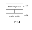
- FIG.2 is a diagram of a structure of a device for sending a reference signal according to an example herein.
- the device contains a determining module 22 arranged for determining, according to a preset mode, a location of a time-frequency resource for sending a reference signal in a Transmission Time Interval (TTI); and a sending module 24 coupled to the determining module 22 and arranged for sending the reference signal according to the location of the time-frequency resource.
- TTI Transmission Time Interval
- the location of the time-frequency resource for sending the reference signal in the TTI may be determined according to the preset mode as follows.
- a subcarrier corresponding to the time-frequency resource may be preset. That is, the reference signal may correspond to a preset subcarrier.
- the reference signal may correspond to one or more symbols meeting a first preset condition in the TTI on the subcarrier.
- the first preset condition may include at least one mode as follows.
- the one or more symbols may be determined according to at least one of a port of an antenna sending a Cell-specific Reference Signal (CRS) or an identification of a cell.
- CRS Cell-specific Reference Signal
- an index n of the one or more symbols may be no less than m.
- the m may be an integer no less than zero.
- the m may be a number of symbols occupied by a Physical Downlink Control Channel (PDCCH).
- the m may be a preset number of symbols.
- the index of the one or more symbols may be an index of a symbol in a time slot.
- CP Cyclic Prefix
- the reference signal may correspond to the subcarrier with an index k ⁇ ⁇ 0, 1, 5, 6, 10, 11 ⁇ .
- the p may be the port of the antenna sending the CRS.
- the reference signal may correspond to the index n ⁇ ⁇ 0, 1, 2, 3, 4, 5, 6 ⁇ on the subcarrier with the index k ⁇ ⁇ 1, 5, 10, 11 ⁇ corresponding to the reference signal.
- the reference signal may correspond to the index n ⁇ ⁇ 1, 2, 3, 5, 6 ⁇ on the subcarrier with the index k ⁇ ⁇ 0, 6 ⁇ corresponding to the reference signal.
- the reference signal may correspond to the index n ⁇ ⁇ 0, 1, 2, 3, 4, 5, 6 ⁇ on the subcarrier with the index k ⁇ ⁇ 1, 5, 10, 11 ⁇ corresponding to the reference signal.
- the reference signal may correspond to the index n ⁇ ⁇ 2, 3, 5, 6 ⁇ on the subcarrier with the index k ⁇ ⁇ 0, 6 ⁇ corresponding to the reference signal.
- the CRS may be sent at the port 0 of the antenna, or at the ports 0 and 1 of the antenna.
- the CRS may be sent at the ports 0, 1, 2, and 3 of the antenna.
- a port number of the antenna for sending the CRS mentioned below may have a similar explanation.
- n ID cell mod 3 1.
- the p may be the port of the antenna sending the CRS.
- the reference signal may correspond to the index n ⁇ ⁇ 0, 1, 2, 3, 4, 5, 6 ⁇ on the subcarrier with the index k ⁇ ⁇ 0, 5, 6, 10, 11 ⁇ corresponding to the reference signal.
- the reference signal may correspond to the index n ⁇ ⁇ 1, 2, 3, 5, 6 ⁇ on the subcarrier with the index k ⁇ ⁇ 1 ⁇ corresponding to the reference signal.
- the reference signal may correspond to the index n ⁇ ⁇ 0, 1, 2, 3, 4, 5, 6 ⁇ on the subcarrier with the index k ⁇ ⁇ 0, 5, 6, 11 ⁇ corresponding to the reference signal.
- the reference signal may correspond to the index n ⁇ ⁇ 1, 2, 3, 5, 6 ⁇ on the subcarrier with the index k ⁇ ⁇ 1, 10 ⁇ corresponding to the reference signal.
- the reference signal may correspond to the index n ⁇ ⁇ 0, 1, 2, 3, 4, 5, 6 ⁇ on the subcarrier with the index k ⁇ ⁇ 0, 5, 6, 11 ⁇ corresponding to the reference signal.
- the reference signal may correspond to the index n ⁇ ⁇ 2, 3, 5, 6 ⁇ on the subcarrier with the index k ⁇ ⁇ 1, 10 ⁇ corresponding to the reference signal.
- n ID cell mod 3 2.
- the p may be the port of the antenna sending the CRS.
- the reference signal may correspond to the index n ⁇ ⁇ 0, 1, 2, 3, 4, 5, 6 ⁇ on the subcarrier with the index k ⁇ ⁇ 0, 1, 5, 6, 10, 11 ⁇ corresponding to the reference signal.
- the reference signal may correspond to the index n ⁇ ⁇ 0, 1, 2, 3, 4, 5, 6 ⁇ on the subcarrier with the index k ⁇ ⁇ 0, 1, 6, 10 ⁇ corresponding to the reference signal.
- the reference signal may correspond to the index n ⁇ ⁇ 1, 2, 3, 5, 6 ⁇ on the subcarrier with the index k ⁇ ⁇ 5, 11 ⁇ corresponding to the reference signal.
- the reference signal may correspond to the index n ⁇ ⁇ 0, 1, 2, 3, 4, 5, 6 ⁇ on the subcarrier with the index k ⁇ ⁇ 0, 1, 6, 10 ⁇ corresponding to the reference signal.
- the reference signal may correspond to the index n ⁇ ⁇ 2, 3, 5, 6 ⁇ on the subcarrier with the index k ⁇ ⁇ 5, 11 ⁇ corresponding to the reference signal.
- the reference signal may correspond to the subcarrier with an index k ⁇ ⁇ 1, 4, 7, 10 ⁇ .
- the subcarrier with the index k ⁇ ⁇ 1, 4, 7, 10 ⁇ may correspond to the index n ⁇ ⁇ 0, 1, 2, 3, 4, 5 ⁇ .
- n ID cell mod 3 1.
- the p may be the port of the antenna sending the CRS.
- the reference signal may correspond to the index n ⁇ ⁇ 1, 2, 4, 5 ⁇ on the subcarrier with the index k ⁇ ⁇ 1, 7 ⁇ corresponding to the reference signal.
- the reference signal may correspond to the index n ⁇ ⁇ 0, 1, 2, 3, 4, 5 ⁇ on the subcarrier with the index k ⁇ ⁇ 4, 10 ⁇ corresponding to the reference signal.
- the reference signal may correspond to the index n ⁇ ⁇ 1, 2, 4, 5 ⁇ on the subcarrier with the index k ⁇ ⁇ 1, 4, 7, 10 ⁇ corresponding to the reference signal.
- the reference signal may correspond to the index n ⁇ ⁇ 2, 4, 5 ⁇ on the subcarrier with the index k ⁇ ⁇ 1, 4, 7, 10 ⁇ corresponding to the reference signal.
- the reference signal may correspond to the subcarrier with an index k ⁇ ⁇ 2, 5, 8, 11 ⁇ .
- the one or more symbols on the subcarrier may be determined according to at least one of the port of the antenna sending the CRS or the identification of the cell in at least one mode as follows.
- the reference signal may correspond to the index n ⁇ ⁇ 0, 1, 2, 3, 4, 5 ⁇ on the subcarrier with the index k ⁇ ⁇ 2, 5, 8, 11 ⁇ corresponding to the reference signal.
- n ID cell mod 3 2.
- the p may be the port of the antenna sending the CRS.
- the reference signal may correspond to the index n ⁇ ⁇ 1, 2, 4, 5 ⁇ on the subcarrier with the index k ⁇ ⁇ 2, 8 ⁇ corresponding to the reference signal.
- the reference signal may correspond to the index n ⁇ ⁇ 0, 1, 2, 3, 4, 5 ⁇ on the subcarrier with the index k ⁇ ⁇ 4, 10 ⁇ corresponding to the reference signal.
- the reference signal may correspond to the index n ⁇ ⁇ 1, 2, 4, 5 ⁇ on the subcarrier with the index k ⁇ ⁇ 2, 5, 8, 11 ⁇ corresponding to the reference signal.
- the reference signal may correspond to the index n ⁇ ⁇ 2, 4, 5 ⁇ on the subcarrier with the index k ⁇ ⁇ 2, 5, 8, 11 ⁇ corresponding to the reference signal.
- the reference signal may correspond to one or more symbols with minimal indices meeting the first preset condition in the TTI.
- the location of the time-frequency resource for sending the reference signal in the TTI may be determined according to the preset mode as follows.
- the reference signal may correspond to one or more symbols meeting a second preset condition in the TTI.
- the reference signal may correspond to a subcarrier on the one or more symbols.
- the subcarrier may be determined according to at least one of a port of an antenna sending a CRS or an identification of a cell.
- the second preset condition may include at least one of the following.
- the one or more symbols may be determined according to at least one of the port of the antenna sending the CRS or the identification of the cell.
- An index n of the one or more symbols may be no less than m.
- the m may be an integer no less than zero.
- the m may be a number of symbols occupied by a PDCCH.
- the m may be a preset number of symbols. If the reference signal corresponds to the subcarrier with an index k ⁇ ⁇ 2, 5, 8, 11 ⁇ , then the n ⁇ ⁇ 0, 1, 2, 3, 4, 5, 6 ⁇ for a normal CP. The n ⁇ ⁇ 0, 1, 2, 3, 4, 5, 6 ⁇ for an extended CP.
- the location of the one or more symbols in the frequency domain may be determined according to at least one of the port of the antenna sending the CRS or the identification of the cell in at least one mode as follows.
- n ID cell mod 3 0.
- the p may be the port of the antenna sending the CRS.
- the reference signal may correspond to the subcarrier with an index k ⁇ ⁇ 1, 2, 3, 4, 5, 7, 8, 9, 10, 11 ⁇ .
- the reference signal may correspond to the subcarrier with the index k ⁇ ⁇ 1, 2, 4, 5, 7, 8, 10, 11 ⁇ .
- n ID cell mod 3 1.
- the p may be the port of the antenna sending the CRS.
- the reference signal may correspond to the subcarrier with the index k ⁇ ⁇ 0, 2, 3, 4, 5, 6, 8, 9, 10, 11 ⁇ .
- the reference signal may correspond to the subcarrier with the index k ⁇ ⁇ 0, 2, 3, 5, 6, 8, 9, 11 ⁇ .
- n ID cell mod 3 2.
- the p may be the port of the antenna sending the CRS.
- the reference signal may correspond to the subcarrier with the index k ⁇ ⁇ 0, 1, 3, 4, 5, 6, 7, 9, 10, 11 ⁇ .
- the reference signal may correspond to the subcarrier with the index k ⁇ ⁇ 0, 1, 3, 4, 6, 7, 9, 10 ⁇ .
- the reference signal may correspond to one or more symbols with minimal indices meeting the second preset condition in the TTI.
- a TTI may be adjacent to one or more symbols in a neighbor TTI.
- the one or more symbols in the neighbor TTI may contain the reference signal.
- the time-frequency resource may correspond to a symbol with an index n ⁇ ⁇ 2, 3, 5, 6 ⁇ for a normal CP.
- the time-frequency resource may correspond to the symbol with the index n ⁇ ⁇ 2, 4, 5 ⁇ for an extended CP.
- the reference signal may correspond to one or more symbols with minimal indices.
- frequency resource allocation in the TTI may be done at a granularity of 12xy subcarriers.
- the y may be an integer greater than 1.
- the reference signal may occupy 1, 2, 3, or 4 of 12 Resource Elements (RE) contained in a PRB on a symbol containing the reference signal.
- the reference signal may occupy REs that are consecutive in the frequency domain.
- An aforementioned example herein may apply to a Base Station (BS).
- An example herein illustrated below may apply to User Equipment (UE) receiving the reference signal.
- BS Base Station
- UE User Equipment
- a device for receiving a reference signal applies to User Equipment (UE).
- the device contains a receiving module arranged for receiving a reference signal sent by a Base Station (BS).
- BS Base Station
- a location of a time-frequency resource for sending the reference signal in a Transmission Time Interval (TTI) is determined according to a preset mode.
- TTI Transmission Time Interval
- the receiving module may be arranged for receiving the reference signal sent by the BS according to the location of the time-frequency resource.
- the BS may determine the location of the time-frequency resource for sending the reference signal in the TTI according to the preset mode.
- the reference signal may correspond to a preset subcarrier.
- the reference signal may correspond to one or more symbols meeting a first preset condition in the TTI on the subcarrier.
- the first preset condition may include at least one mode as follows.
- the one or more symbols may be determined according to at least one of a port of an antenna sending a Cell-specific Reference Signal (CRS) or an identification of a cell.
- CRS Cell-specific Reference Signal
- an index n of the one or more symbols may be no less than m.
- the m may be an integer no less than zero.
- the m may be a number of symbols occupied by a Physical Downlink Control Channel (PDCCH).
- the m may be a preset number of symbols.
- the index of the one or more symbols may be an index of a symbol in a time slot.
- CP Cyclic Prefix
- the reference signal may correspond to the subcarrier with an index k ⁇ ⁇ 0, 1, 5, 6, 10, 11 ⁇ .
- the p may be the port of the antenna sending the CRS.
- the reference signal may correspond to the index n ⁇ ⁇ 0, 1, 2, 3, 4, 5, 6 ⁇ on the subcarrier with the index k ⁇ ⁇ 1, 5, 10, 11 ⁇ corresponding to the reference signal.
- the reference signal may correspond to the index n ⁇ ⁇ 1, 2, 3, 5, 6 ⁇ on the subcarrier with the index k ⁇ ⁇ 0, 6 ⁇ corresponding to the reference signal.
- the reference signal may correspond to the index n ⁇ ⁇ 0, 1, 2, 3, 4, 5, 6 ⁇ on the subcarrier with the index k ⁇ ⁇ 1, 5, 10, 11 ⁇ corresponding to the reference signal.
- the reference signal may correspond to the index n ⁇ ⁇ 2, 3, 5, 6 ⁇ on the subcarrier with the index k ⁇ ⁇ 0, 6 ⁇ corresponding to the reference signal.
- the CRS may be sent at the port 0 of the antenna, or at the ports 0 and 1 of the antenna.
- the CRS may be sent at the ports 0, 1, 2, and 3 of the antenna.
- a port number of the antenna for sending the CRS mentioned below may have a similar explanation.
- n ID cell mod 3 1.
- the p may be the port of the antenna sending the CRS.
- the reference signal may correspond to the index n ⁇ ⁇ 0, 1, 2, 3, 4, 5, 6 ⁇ on the subcarrier with the index k ⁇ ⁇ 0, 5, 6, 10, 11 ⁇ corresponding to the reference signal.
- the reference signal may correspond to the index n ⁇ ⁇ 1, 2, 3, 5, 6 ⁇ on the subcarrier with the index k ⁇ ⁇ 1 ⁇ corresponding to the reference signal.
- the reference signal may correspond to the index n ⁇ ⁇ 0, 1, 2, 3, 4, 5, 6 ⁇ on the subcarrier with the index k ⁇ ⁇ 0, 5, 6, 11 ⁇ corresponding to the reference signal.
- the reference signal may correspond to the index n ⁇ ⁇ 1, 2, 3, 5, 6 ⁇ on the subcarrier with the index k ⁇ ⁇ 1, 10 ⁇ corresponding to the reference signal.
- the reference signal may correspond to the index n ⁇ ⁇ 0, 1, 2, 3, 4, 5, 6 ⁇ on the subcarrier with the index k ⁇ ⁇ 0, 5, 6, 11 ⁇ corresponding to the reference signal.
- the reference signal may correspond to the index n ⁇ ⁇ 2, 3, 5, 6 ⁇ on the subcarrier with the index k ⁇ ⁇ 1, 10 ⁇ corresponding to the reference signal.
- n ID cell mod 3 2.
- the p may be the port of the antenna sending the CRS.
- the reference signal may correspond to the index n ⁇ ⁇ 0, 1, 2, 3, 4, 5, 6 ⁇ on the subcarrier with the index k ⁇ ⁇ 0, 1, 5, 6, 10, 11 ⁇ corresponding to the reference signal.
- the reference signal may correspond to the index n ⁇ ⁇ 0, 1, 2, 3, 4, 5, 6 ⁇ on the subcarrier with the index k ⁇ ⁇ 0, 1, 6, 10 ⁇ corresponding to the reference signal.
- the reference signal may correspond to the index n ⁇ ⁇ 1, 2, 3, 5, 6 ⁇ on the subcarrier with the index k ⁇ ⁇ 5, 11 ⁇ corresponding to the reference signal.
- the reference signal may correspond to the index n ⁇ ⁇ 0, 1, 2, 3, 4, 5, 6 ⁇ on the subcarrier with the index k ⁇ ⁇ 0, 1, 6, 10 ⁇ corresponding to the reference signal.
- the reference signal may correspond to the index n ⁇ ⁇ 2, 3, 5, 6 ⁇ on the subcarrier with the index k ⁇ ⁇ 5, 11 ⁇ corresponding to the reference signal.
- the reference signal may correspond to the subcarrier with an index k ⁇ ⁇ 1, 4, 7, 10 ⁇ .
- the subcarrier with the index k ⁇ ⁇ 1, 4, 7, 10 ⁇ may correspond to the index n ⁇ ⁇ 0, 1, 2, 3, 4, 5 ⁇ .
- n ID cell mod 3 1.
- the p may be the port of the antenna sending the CRS.
- the reference signal may correspond to the index n ⁇ ⁇ 1, 2, 4, 5 ⁇ on the subcarrier with the index k ⁇ ⁇ 1, 7 ⁇ corresponding to the reference signal.
- the reference signal may correspond to the index n ⁇ ⁇ 0, 1, 2, 3, 4, 5 ⁇ on the subcarrier with the index k ⁇ ⁇ 4, 10 ⁇ corresponding to the reference signal.
- the reference signal may correspond to the index n ⁇ ⁇ 1, 2, 4, 5 ⁇ on the subcarrier with the index k ⁇ ⁇ 1, 4, 7, 10 ⁇ corresponding to the reference signal.
- the reference signal may correspond to the index n ⁇ ⁇ 2, 4, 5 ⁇ on the subcarrier with the index k ⁇ ⁇ 1, 4, 7, 10 ⁇ corresponding to the reference signal.
- the reference signal may correspond to the subcarrier with an index k ⁇ ⁇ 2, 5, 8, 11 ⁇ .
- the one or more symbols on the subcarrier may be determined according to at least one of the port of the antenna sending the CRS or the identification of the cell in at least one mode as follows.
- the reference signal may correspond to the index n ⁇ ⁇ 0, 1, 2, 3, 4, 5 ⁇ on the subcarrier with the index k ⁇ ⁇ 2, 5, 8, 11 ⁇ corresponding to the reference signal.
- n ID cell mod 3 2.
- the p may be the port of the antenna sending the CRS.
- the reference signal may correspond to the index n ⁇ ⁇ 1, 2, 4, 5 ⁇ on the subcarrier with the index k ⁇ ⁇ 2, 8 ⁇ corresponding to the reference signal.
- the reference signal may correspond to the index n ⁇ ⁇ 0, 1, 2, 3, 4, 5 ⁇ on the subcarrier with the index k ⁇ ⁇ 4, 10 ⁇ corresponding to the reference signal.
- the reference signal may correspond to the index n ⁇ ⁇ 1, 2, 4, 5 ⁇ on the subcarrier with the index k ⁇ ⁇ 2, 5, 8, 11 ⁇ corresponding to the reference signal.
- the reference signal may correspond to the index n ⁇ ⁇ 2, 4, 5 ⁇ on the subcarrier with the index k ⁇ ⁇ 2, 5, 8, 11 ⁇ corresponding to the reference signal.
- the reference signal may correspond to one or more symbols with minimal indices meeting the first preset condition in the TTI.
- the location of the time-frequency resource for sending the reference signal in the TTI may be determined according to the preset mode as follows.
- the reference signal may correspond to one or more symbols meeting a second preset condition in the TTI.
- the reference signal may correspond to a subcarrier on the one or more symbols.
- the subcarrier may be determined according to at least one of a port of an antenna sending a CRS or an identification of a cell.
- the second preset condition may include at least one of the following.
- the one or more symbols may be determined according to at least one of the port of the antenna sending the CRS or the identification of the cell.
- An index n of the one or more symbols may be no less than m.
- the m may be an integer no less than zero.
- the m may be a number of symbols occupied by a PDCCH.
- the m may be a preset number of symbols. If the reference signal corresponds to the subcarrier with an index k ⁇ ⁇ 2, 5, 8, 11 ⁇ , then the n ⁇ ⁇ 0, 1, 2, 3, 4, 5, 6 ⁇ for a normal CP. The n ⁇ ⁇ 0, 1, 2, 3, 4, 5, 6 ⁇ for an extended CP.
- the location of the one or more symbols in the frequency domain may be determined according to at least one of the port of the antenna sending the CRS or the identification of the cell in at least one mode as follows.
- n ID cell mod 3 0.
- the p may be the port of the antenna sending the CRS.
- the reference signal may correspond to the subcarrier with an index k ⁇ ⁇ 1, 2, 3, 4, 5, 7, 8, 9, 10, 11 ⁇ .
- the reference signal may correspond to the subcarrier with the index k ⁇ ⁇ 1, 2, 4, 5, 7, 8, 10, 11 ⁇ .
- n ID cell mod 3 1.
- the p may be the port of the antenna sending the CRS.
- the reference signal may correspond to the subcarrier with the index k ⁇ ⁇ 0, 2, 3, 4, 5, 6, 8, 9, 10, 11 ⁇ .
- the reference signal may correspond to the subcarrier with the index k ⁇ ⁇ 0, 2, 3, 5, 6, 8, 9, 11 ⁇ .
- n ID cell mod 3 2.
- the p may be the port of the antenna sending the CRS.
- the reference signal may correspond to the subcarrier with the index k ⁇ ⁇ 0, 1, 3, 4, 5, 6, 7, 9, 10, 11 ⁇ .
- the reference signal may correspond to the subcarrier with the index k ⁇ ⁇ 0, 1, 3, 4, 6, 7, 9, 10 ⁇ .
- the reference signal may correspond to one or more symbols with minimal indices meeting the second preset condition in the TTI.
- a TTI may be adjacent to one or more symbols in a neighbor TTI.
- the one or more symbols in the neighbor TTI may contain the reference signal.
- the time-frequency resource may correspond to a symbol with an index n ⁇ ⁇ 2, 3, 5, 6 ⁇ for a normal CP.
- the time-frequency resource may correspond to the symbol with the index n ⁇ ⁇ 2, 4, 5 ⁇ for an extended CP.
- the reference signal may correspond to one or more symbols with minimal indices.
- frequency resource allocation in the TTI may be done at a granularity of 12xy subcarriers.
- the y may be an integer greater than 1.
- the reference signal may occupy 1, 2, 3, or 4 of 12 Resource Elements (RE) contained in a PRB on a symbol containing the reference signal.
- the reference signal may occupy REs that are consecutive in the frequency domain.
- the present discloser is exemplified below according to an example herein.
- a design for a DMRS for a TTI of 0.5ms is provided.
- the design may apply beyond a DMRS as needed.
- An existing mode of the DMRS may lag behind in a short TTI, which is against lowering a processing delay of/for UE.
- the location of the DMRS may be moved forward. As the DMRS is UE specific, changing the location of the DMRS will not impact legacy UE. By advancing the location of the DMRS, UE is allowed to assess and decode a channel in time.
- the location of the DMRS may be advanced given that the advanced location of the DMRS is not in conflict with the location of a CRS.
- the present discloser is exemplified below respectively with an odd time slot and an even time slot.
- An odd time slot may refer to a second time slot in an existing Long Term Evolution (LTE) subframe.
- LTE Long Term Evolution
- the location of the DMRS may not be in conflict with the location of a CRS.
- the location of the DMRS may be determined in at least one mode as follows. In a mode that follows, for a normal CP, there may be 7 OFDM symbols in a time slot, with integer indices 0 to 6 in chronological order, respectively. For an extended CP, there may be 6 OFDM symbols in a time slot, with integer indices 0 to 5 in chronological order, respectively. Subcarriers in a PRB may be given indices 0 to 11 in ascending frequencies.
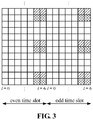
- FIG.3 is a diagram of a location of a time-frequency resource for sending an existing DMRS under a normal Cyclic Prefix (CP) according to an example herein.
- CP Cyclic Prefix
- an RE with diagonals may be a time-frequency resource corresponding to ports 7, 8, 11, and 13 of an antenna.
- An RE with a grid may be a time-frequency resource corresponding to ports 9, 10, 12, and 14 of the antenna.
- FIG.4 is a diagram of the location after a translation of the existing DMRS in a time domain according to an example herein.
- a darkened RE may be a time-frequency resource corresponding to a CRS.
- the CRS may be sent at a port 4 of the antenna.
- the location of the time-frequency resource of the CRS is determined according to an identification (ID) of a cell
- the location of the frequency resource of the DMRS may be determined according to the ID of the cell as well.
- the "mod" may refer to a modulus operator.
- the location of the time-frequency resource of the DMRS may be determined according to a maximal port number of the antenna. As shown in FIG.2 , no matter what the real port number of the antenna for the CRS is, the location of the time resource of the DMRS may be determined according to the port 4 of the antenna for the CRS.
- the location of the time-frequency resource of the DMRS may be determined according to the real port number of the antenna for the CRS.
- FIG.5 is a diagram of a location of a time-frequency resource for sending a DMRS according to an example herein, when the real port number of the antenna for the CRS is 2.
- the CP may be normal.
- the DMRS may occupy a preset number of symbols, which is not limited to 2 as in existing LTE. Different subcarriers may correspond to different numbers of symbols. For example, one subcarrier may correspond to 1 symbol, and another subcarrier may correspond to 2 symbols. However, on each subcarrier, the DMRS may always occupy one or more symbols with minimal indices beyond symbols occupied by the CRS.
- the above may be expressed below using mathematical formulas.
- the DMRS may correspond to the subcarrier with an index k ⁇ ⁇ 0, 1, 5, 6, 10, 11 ⁇ for the normal CP.
- the p may be the port of the antenna sending the CRS.
- the DMRS may correspond to the subcarrier with the index k ⁇ ⁇ 1, 5, 10, 11 ⁇ , which may bear no CRS.
- the DMRS may correspond to the index n ⁇ ⁇ 0, 1, 2, 3, 4, 5, 6 ⁇ on the subcarrier.
- the two symbols with minimal indices 0 and 1 may be taken for the DMRS.
- the DMRS may correspond to the subcarrier with the index k ⁇ 0, 6 ⁇ .
- the first symbol on the subcarrier may bear the CRS, and may not transmit DMRS.
- the DMRS may correspond to the index n ⁇ ⁇ 1, 2, 3, 5, 6 ⁇ on the subcarrier.
- the two symbols with minimal indices 1 and 2 may be taken for the DMRS.
- the DMRS may correspond to the subcarrier with the index k ⁇ ⁇ 1, 5, 10, 11 ⁇ .
- the e subcarrier may bear no CRS.
- the DMRS may correspond to the index n ⁇ ⁇ 0, 1, 2, 3, 4, 5, 6 ⁇ on the subcarrier.
- the two symbols with minimal indices 0 and 1 may be taken for the DMRS.
- the DMRS may correspond to the subcarrier with the index k ⁇ ⁇ 0, 6 ⁇ .
- the first two symbols on the subcarrier may bear the CRS, and may not transmit DMRS.
- the DMRS may correspond to the index n ⁇ ⁇ 2, 3, 5, 6 ⁇ on the subcarrier.
- the two symbols with minimal indices 2 and 3 may be taken for the DMRS.
- n ID cell mod 3 1.
- the p may be the port of the antenna sending the CRS.
- the DMRS may correspond to the index n ⁇ ⁇ 0, 1, 2, 3, 4, 5, 6 ⁇ on the subcarrier with the index k ⁇ ⁇ 0, 5, 6, 10, 11 ⁇ corresponding to the DMRS.
- the DMRS may correspond to the index n ⁇ ⁇ 1, 2, 3, 5, 6 ⁇ on the subcarrier with the index k ⁇ ⁇ 1 ⁇ corresponding to the DMRS.
- the DMRS may correspond to the index n ⁇ ⁇ 0, 1, 2, 3, 4, 5, 6 ⁇ on the subcarrier with the index k ⁇ ⁇ 0, 5, 6, 11 ⁇ corresponding to the DMRS.
- the DMRS may correspond to the index n ⁇ ⁇ 1, 2, 3, 5, 6 ⁇ on the subcarrier with the index k ⁇ ⁇ 1, 10 ⁇ corresponding to the DMRS.
- the DMRS may correspond to the index n ⁇ ⁇ 0, 1, 2, 3, 4, 5, 6 ⁇ on the subcarrier with the index k ⁇ ⁇ 0, 5, 6, 11 ⁇ corresponding to the DMRS.
- the DMRS may correspond to the index n ⁇ ⁇ 2, 3, 5, 6 ⁇ on the subcarrier with the index k ⁇ ⁇ 1, 10 ⁇ corresponding to the DMRS.
- n ID cell mod 3 2.
- the p may be the port of the antenna sending the CRS.
- the DMRS may correspond to the index n ⁇ ⁇ 0, 1, 2, 3, 4, 5, 6 ⁇ on the subcarrier with the index k ⁇ ⁇ 0, 1, 5, 6, 10, 11 ⁇ corresponding to the DMRS.
- the DMRS may correspond to the index n ⁇ ⁇ 0, 1, 2, 3, 4, 5, 6 ⁇ on the subcarrier with the index k ⁇ ⁇ 0, 1, 6, 10 ⁇ corresponding to the DMRS.
- the DMRS may correspond to the index n ⁇ ⁇ 1, 2, 3, 5, 6 ⁇ on the subcarrier with the index k ⁇ ⁇ 5, 11 ⁇ corresponding to the DMRS.
- the DMRS may correspond to the index n ⁇ ⁇ 0, 1, 2, 3, 4, 5, 6 ⁇ on the subcarrier with the index k ⁇ ⁇ 0, 1, 6, 10 ⁇ corresponding to the DMRS.
- the DMRS may correspond to the index n ⁇ ⁇ 2, 3, 5, 6 ⁇ on the subcarrier with the index k ⁇ ⁇ 5, 11 ⁇ corresponding to the DMRS.
- the DMRS may correspond to the subcarrier with an index k ⁇ ⁇ 1, 4, 7, 10 ⁇ .
- the subcarrier with the index k ⁇ ⁇ 1, 4, 7, 10 ⁇ may correspond to the index n ⁇ ⁇ 0, 1, 2,3,4,5 ⁇ .
- n ID cell mod 3 1.
- the p may be the port of the antenna sending the CRS.
- the DMRS may correspond to the index n ⁇ ⁇ 1, 2, 4, 5 ⁇ on the subcarrier with the index k ⁇ ⁇ 1, 7 ⁇ corresponding to the DMRS.
- the DMRS may correspond to the index n ⁇ ⁇ 0, 1, 2, 3, 4, 5 ⁇ on the subcarrier with the index k ⁇ ⁇ 4, 10 ⁇ corresponding to the DMRS.
- the DMRS may correspond to the index n ⁇ ⁇ 1, 2, 4, 5 ⁇ on the subcarrier with the index k ⁇ ⁇ 1, 4, 7, 10 ⁇ corresponding to the DMRS.
- the DMRS may correspond to the index n ⁇ ⁇ 2, 4, 5 ⁇ on the subcarrier with the index k ⁇ ⁇ 1, 4, 7, 10 ⁇ corresponding to the DMRS.
- the DMRS may correspond to the subcarrier with an index k ⁇ ⁇ 2, 5, 8, 11 ⁇ .
- the one or more symbols on the subcarrier may be determined according to at least one of the port of the antenna sending the CRS or the identification of the cell in at least one mode as follows.
- the DMRS may correspond to the index n ⁇ ⁇ 0, 1, 2, 3, 4, 5 ⁇ on the subcarrier with the index k ⁇ ⁇ 2, 5, 8, 11 ⁇ corresponding to the DMRS.
- n ID cell mod 3 2.
- the p may be the port of the antenna sending the CRS.
- the DMRS may correspond to the index n ⁇ ⁇ 1, 2, 4, 5 ⁇ on the subcarrier with the index k ⁇ ⁇ 2, 8 ⁇ corresponding to the DMRS.
- the DMRS may correspond to the index n ⁇ ⁇ 0, 1, 2, 3, 4, 5 ⁇ on the subcarrier with the index k ⁇ ⁇ 4, 10 ⁇ corresponding to the DMRS.
- the DMRS may correspond to the index n ⁇ ⁇ 1, 2, 4, 5 ⁇ on the subcarrier with the index k ⁇ ⁇ 2, 5, 8, 11 ⁇ corresponding to the DMRS.
- the DMRS may correspond to the index n ⁇ ⁇ 2, 4, 5 ⁇ on the subcarrier with the index k ⁇ ⁇ 1, 4, 7, 10 ⁇ corresponding to the DMRS.
- the location of the DMRS in the frequency domain may be preset, without being limited to the location of the DMRS in the frequency domain in existing LTE.
- the DMRS may be located at subcarrier index 2 in the frequency domain.
- subcarrier index 2 may bear no CRS. Then, the DMRS may occupy the time resource of symbols 0 and 1.
- the location of the DMRS in the frequency domain may remain the same as that in related art.
- the DMRS may be moved in the time domain onto a symbol bearing no CRS.
- the location of the time-frequency resource of the DMRS may be determined according to a maximal port number of the antenna. Alternatively, the location of the time-frequency resource of the DMRS may be determined according to the real port number of the antenna for the CRS.
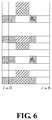
- FIG.6 is a diagram of a DMRS being moved in the time domain onto a symbol bearing no Cell-specific Reference Signal (CRS), with a location of the DMRS in a frequency domain remaining the same as that in related art according to an example herein.
- CRS Cell-specific Reference Signal
- the DMRS may occupy a preset location in the frequency domain, which is not limited to the location of the DMRS in the frequency domain as in existing LTE.
- the DMRS may occupy a preset number of symbols, which is not limited to 2 as in existing LTE. Different subcarriers may correspond to different numbers of symbols. For example, one subcarrier may correspond to 1 symbol, and another subcarrier may correspond to 2 symbols. However, a DMRS-bearing symbol may bear no CRS.
- FIG.7 is a diagram of moving a DMRS in related art onto two foremost symbols, and placing the DMRS at a location beyond that of a CRS in the frequency domain according to an example herein.
- a mode 3 when the port number of the antenna for the CRS is 4, the two foremost symbols may be occupied by the CRS. Accordingly, an RE occupied by (or bearing) the CRS may not be available/selected.
- ID identification
- the location of the frequency resource of the DMRS may be determined according to the ID of the cell as well.
- the above may be expressed below using mathematical formulas, which may apply to both the normal CP and the extended CP.
- the p may be the port of the antenna sending the CRS.
- the DMRS may correspond to the subcarrier with an index k ⁇ ⁇ 1, 2, 3, 4, 5, 7, 8, 9, 10, 11 ⁇ .
- the DMRS may correspond to the subcarrier with the index k ⁇ ⁇ 1, 2, 4, 5, 7, 8, 10, 11 ⁇ .
- n ID cell mod 3 1.
- the p may be the port of the antenna sending the CRS.
- the DMRS may correspond to the subcarrier with the index k ⁇ ⁇ 0, 2, 3, 4, 5, 6, 8, 9, 10, 11 ⁇ .
- the DMRS may correspond to the subcarrier with the index k ⁇ ⁇ 0, 2, 3, 5, 6, 8, 9, 11 ⁇ .
- n ID cell mod 3 2.
- the p may be the port of the antenna sending the CRS.
- the DMRS may correspond to the subcarrier with the index k ⁇ ⁇ 0, 1, 3, 4, 5, 6, 7, 9, 10, 11 ⁇ .
- the DMRS may correspond to the subcarrier with the index k ⁇ ⁇ 0, 1, 3, 4, 6, 7, 9, 10 ⁇ .
- the DMRS may occupy a preset number of symbols, which is not limited to 2 as in existing LTE. Different subcarriers may correspond to different numbers of symbols. For example, one subcarrier may correspond to 1 symbol, and another subcarrier may correspond to 2 symbols. However, on each subcarrier, the DMRS may always occupy one or more symbols with minimal indices in the TTI.
- An even time slot may refer to a first time slot in an existing LTE subframe.
- a starting location of the DMRS may further depend on a PDCCH zone.
- the DMRS may not be located on a symbol bearing a PDCCH.
- the DMRS may occupy a preset number of symbols, such as a maximal number of symbols bearing the PDCCH.
- the DMRS may not be located on the maximal number of symbols bearing the PDCCH.
- a maximal number of 3 symbols may bear the PDCCH.
- the DMRS may occupy a 4th symbol and a symbol thereafter.
- the DMRS may be designed according to a number of symbols that actually bear the PDCCH. For example, 1 symbol may actually bear the PDCCH. Accordingly, the DMRS may occupy a 2nd symbol and a symbol thereafter.
- the location of the DMRS in the frequency domain may remain the same as that in related art.
- the DMRS may be located, in the time domain, on a symbol with a minimal index beyond an RE bearing the CRS and beyond a symbol bearing the PDCCH or a preset number of symbols.
- a number of symbols bearing the PDCCH may be the maximal number of symbols bearing the PDCCH.
- the number of symbols bearing the PDCCH may be the number of symbols that actually bear the PDCCH.
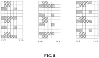
- FIG.8 is a diagram of a location in the time domain being a symbol with a minimal index beyond a Resource Element (RE) bearing a CRS and beyond a symbol bearing a Physical Downlink Control Channel (PDCCH) or a preset number of symbols according to an example herein.
- the CRS may be sent at the port 4 of the antenna.
- a number of 1 symbol may bear the PDCCH.
- the DMRS may be located on a symbol beyond the symbol that actually bears the PDCCH.
- the location of the time-frequency resource of the DMRS may be determined according to a maximal port number of the antenna. Alternatively, the location of the time-frequency resource of the DMRS may be determined according to the real port number of the antenna for the CRS.
- the location of the DMRS in the frequency domain may remain the same as that in related art.
- the DMRS may be moved in the time domain onto a symbol bearing no CRS, beyond a symbol bearing the PDCCH or a preset number of symbols.
- a number of symbols bearing the PDCCH may be the maximal number of symbols bearing the PDCCH.
- the number of symbols bearing the PDCCH may be the number of symbols that actually bear the PDCCH.
- the location of the time-frequency resource of the DMRS may be determined according to a maximal port number of the antenna. Alternatively, the location of the time-frequency resource of the DMRS may be determined according to the real port number of the antenna for the CRS.
- the DMRS in related art may be moved onto two foremost symbols, beyond a symbol bearing the PDCCH or a preset number of symbols, with a changed location of the DMRS in the frequency domain.
- a number of symbols bearing the PDCCH may be the maximal number of symbols bearing the PDCCH.
- the number of symbols bearing the PDCCH may be the number of symbols that actually bear the PDCCH.
- the location of the time-frequency resource of the CRS is determined according to an identification (ID) of a cell
- ID identification
- the location of the frequency resource of the DMRS may be determined according to the ID of the cell as well.
- DMRS configuration in the odd time slot and in the even time slot may be identical.
- the DMRS configuration in both the odd time slot and the even time slot may be determined according to a mode of the even time slot.
- a DMRS design for a TTI of 3 or 4 symbols may be provided.
- FIG.9 is a diagram of a definition of a Transmission Time Interval (TTI) according to an example herein.
- TTI Transmission Time Interval
- the method according to an example herein may apply, but is not limited to, the definition of the TTI.
- the DMRS may be located in a TTI 1 and a TTI 3.
- the location of the time-frequency resource occupied by the DMRS may be determined in a mode similar to the three modes in Example 1, as shown in FIG.9 .
- symbols with indices 3, 4, and 5 may be occupied in both the TTI 1 and the TTI 3.
- the DMRS may occupy two foremost symbols in a TTI in the time domain.
- the DMRS may occupy a carrier bearing no CRS in the frequency domain.
- the TTI 1 may differ from the TTI 3 in that the TTI 1 may depend on the number of symbols bearing the PDCCH.
- the DMRS may have to be located on a symbol beyond the symbol bearing the PDCCH in the time domain, similar to the case with the even time slot.
- FIG.9 gives an example of the DMRS with a mode similar to the mode 3 according to an example herein.
- demodulation may be done using the CRS.
- demodulation may be done using the DMRS, or using the CRS of the TTI 0 and the TTI 2, respectively.
- the DMRS may be placed in a location in the TTI 1 that differs from that in the TTI 3.
- each TTI contains a reference signal for demodulation.
- Application may go beyond an example herein.
- Each TTI may contain a DMRS.
- the location of the DMRS may be determined according to the three modes in Example 1.
- a DMRS design for a TTI of 2 or 3 symbols may be provided.
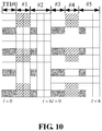
- FIG.10 is a diagram of a definition of a TTI according to an example herein.
- a time slot may be divided into 3 TTIs.
- the TTIs in FIG.10 may have a number of symbols of 2, 2, 3.
- the TTIs in FIG.10 may have a number of symbols of 3, 2, 2.
- the TTIs in FIG.10 may have a number of symbols of 2,3, 2.
- the method according to an example herein may apply, but is not limited to, the definition of the TTI.
- the CRS may be sent at a port 4 of the antenna. Assume that the PDCCH occupies but two foremost symbols.
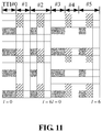
- FIG.11 is a diagram of a definition of a TTI according to an example herein.
- the DMRS may be located in the TTI 1 and the TTI 4. For the TTIs 0, 2, 3, and 5, demodulation may be done using the CRS. For the TTIs 1 and 4, demodulation may be done using the DMRS. In FIG.11 , the DMRS may be located in the TTIs 1, 2, 4, and 5. For the TTIs 0 and 3, demodulation may be done using the CRS. For the TTIs 1, 2, 4, and 5, demodulation may be done using the CRS /DMRS.
- Each TTI may contain a DMRS.
- the location of the DMRS may be determined according to the three modes in Example 1.
- a DMRS design for a TTI of 1 symbol may be provided.
- FIG.12 is a diagram of a design of a DMRS according to an example herein. As shown in FIG.12 , symbols 0, 1, 4, 7, 8, and 11 may bear the CRS. Demodulation may be done using the CRS.
- Symbols 3, 6, 10, and 13 may bear the DMRS.
- Demodulation may be done using the DMRS.
- Symbols2, 5, 9, and 12 may bear neither the CRS nor the DMRS. Demodulation may be done using the CRS of a previous symbol.
- Each TTI may contain a DMRS.
- the location of the DMRS may be determined according to the three modes in Example 1.
- Evolved NodeB For a Channel-State Information reference signal (CSI-RS) sent over a full bandwidth with a location that possibly conflicts with the location of the time-frequency resource of the DMRS, an eNB may avoid scheduling UE using demodulation with the DMRS. Alternatively, the eNB may puncture a conflicting RE to remove the DMRS or the CSI-RS.
- CSI-RS Channel-State Information reference signal
- the DMRS may be sent to UE on a PRB beyond a bandwidth of a Positioning Reference Signal (PRS).
- PRS Positioning Reference Signal
- the eNB may puncture a conflicting RE to remove the DMRS or the PRS.
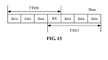
- FIG.13 is a diagram of a definition of a TTI according to an example herein. As shown in FIG.13 , a time slot in the uplink may be divided into two TTIs 0 and 1. A symbol in one of the TTIs 0 and 1 may be adjacent to the other TTI. The DMRS for both TTIs may be located on the symbol.
- SC-FDMA Single-Carrier Frequency-Division Multiple Access
- Two UE DMRSs in the TTIs 0 and 1 may be made orthogonal to each other by predefinition or configuration, avoiding interference between the DMRSs in the two TTIs.
- n cs n DMRS 1 + n DMRS 2 + n PRS n s mode 12 , where the n DMRS 2 may be a cyclic shift indicated in Downlink Control Information (DCI).
- DCI Downlink Control Information
- the DMRS in the two TTIs may be made orthogonal to each other.
- a Physical Uplink Shared Channel (PUSCH) of UE scheduled in the neighbor TTIs 0 and 1 may have to occupy an identical resource.
- PUSCH Physical Uplink Shared Channel
- Placing the DMRS at the end of the TTI 0 may impact a processing delay. Given a relatively large processing capacity of the eNB, the impact may be ignored.
- FIG.13 may apply to the normal CP.
- the time slot in the uplink may be divided into two TTIs 0 and 1.
- the TTI 0 may contain the 3 foremost symbols.
- the TTI 1 may contain the last 4 symbols.
- the TTI 0 may contain the 4 foremost symbols.
- the TTI 1 may contain the last 3 symbols.
- the DMRS may be sent on the center symbol in the time slot.
- a granularity for frequency resource allocation for UE may increase.
- the k may be an integer greater than 1.
- the k may take on a value of 1, 2, 3, 4, 5, etc.
- a granularity for frequency resource allocation may be 24 subcarriers. That is, resources of multiples of 24 subcarriers in the frequency domain and 0.5ms in the time domain may be allocated to UE.
- the granularity for frequency resource allocation may vary over time. For example, for a system with a TTI of 0.5ms, a granularity for frequency resource allocation in the odd time slot may be 12 subcarriers. A granularity for frequency resource allocation in the even time slot may be 24 subcarriers. Alternatively, the granularity for frequency resource allocation may depend on the size of the TTI. For example, in case of a TTI of 3 or 4 symbols as in Example 2, the granularity for frequency resource allocation may be 4x12 subcarriers for a TTI of 3 symbols. The granularity for frequency resource allocation may be 3x12 subcarriers for a TTI of 4 symbols.
- UE may be configured with the granularity for frequency resource allocation by the eNB.
- 12 RE contained in a PRB may contain an RS density in the frequency domain same as that in related art. That is, 3 or 4 REs may be used for RS transmission. The density may be less. For example, 1 or 2 REs out of the 12 RE may be used for RS transmission.
- inter-UE DMRS multiplexing by spectrum spreading in the time domain may no longer apply. Instead, spectrum spreading may be down in the frequency domain.
- the RS density in the frequency domain may be 2 or 4. 2 or 4 consecutive REs in the frequency domain may be occupied.
- Spectrum spreading for DMRSs of different UE may be done (i.e., performed) among 2 or 4 REs in the frequency domain.
- An RS may have to occupy an RE bearing no existing CSI-RS, to avoid a conflict with an existing CSI-RS.
- the DMRS sent to UE using demodulation with the CRS may share the port of the CRS, further increasing a density at a port of the CRS, such as in case of a high rate or a poor channel.
- a computer-readable storage medium may have stored therein instructions that when executed by a processor, cause the processor to perform steps as follows.
- step S1 a location of a time-frequency resource for sending a reference signal in a Transmission Time Interval (TTI) is determined according to a preset mode.
- TTI Transmission Time Interval
- step S2 the reference signal is sent according to the location of the time-frequency resource.
- modules or steps in examples herein may be realized using a universal computing device, and may be integrated in a single computing device or distributed in a network formed by multiple computing devices.
- they may be realized using computing device executable program codes, and thus may be stored in a storage device and executed by a computing device.
- the steps may be executed in an order different from that illustrated or described here, or may each be made into an Integrated Circuit module.
- Multiple modules or steps herein may be realized by being made into a single Integrated Circuit module.
- an example herein is not limited to a specific combination of hardware and software.
- a location of a time-frequency resource for sending the reference signal in a TTI is determined according to a preset mode.
- the reference signal is sent according to the location of the time-frequency resource. Accordingly, a location of the DMRS may be altered, lowering a processing delay for UE, avoiding a major processing delay for UE caused by a DMRS being located further back or lagging behind in related art.
Landscapes
- Engineering & Computer Science (AREA)
- Signal Processing (AREA)
- Computer Networks & Wireless Communication (AREA)
- Mobile Radio Communication Systems (AREA)
Claims (9)
- Verfahren zum Senden eines Referenzsignals, das von einer Basisstation, BS, durchgeführt wird, umfassend :Ermitteln (S102), durch die BS, gemäß einem voreingestellten Modus, einer Stelle einer Zeit-Frequenz-Ressource, die zum Senden des Referenzsignals in einem Übertragungszeitintervall, TTI, zugewiesen ist ; undSenden (S104), durch die BS, an eine Benutzerausrüstung, UE, des Referenzsignals gemäß der Stelle der Zeit-Frequenz-Ressource,wobei für das TTI einer Dauer eines Zeitschlitzes, für einen normalen zyklischen Präfix, CP, die Zeit-Frequenz-Ressource einem Symbol mit einem Index n ∈ {2, 3} entspricht und ein Subträger mit einem Index k ∈ {0, 1, 5, 6, 10, 11} in einem physischen Ressourcenblock, PRB, entspricht,wobei Symbolen in dem TTI Indizes 0, 1, 2, 3, 4, 5 und 6 gegeben werden,wobei Subträgern in dem PRB Indizes 0 bis 11 in aufsteigenden Frequenzen gegeben werden.
- Verfahren nach Anspruch 1,wobei das Referenzsignal den Subträger belegt, der vorgegeben ist,wobei das Referenzsignal ein oder mehrere Symbole belegt, die eine erste vorgegebene Bedingung in dem TTI auf dem Subträger erfüllt,wobei die erste vorgegebene Bedingung mindestens eines des Folgenden umfasst:das eine oder die mehreren Symbole werden gemäß dem mindestens einen eines Anschlusses einer Antenne, die ein zellspezifisches Referenzsignal, CRS, oder eine Kennung einer Zelle sendet, ermittelt; oderder Index n des einen oder der mehreren Symbole ist nicht kleiner als eine Ganzzahl m, die nicht kleiner als null ist, wobei das m eine Zahl von Symbolen, die von einem physischen Abwärtsstreckensteuerungskanal, PDCCH, belegt werden, oder eine vorgegebene Zahl von Symbolen ist, wobei der Index des einen oder der mehreren Symbole der Index eines Symbols in dem Zeitschlitz ist, wobei das n ∈ {0, 1, 2, 3, 4, 5, 6} für den normalen CP, das n ∈ {0, 1, 2, 3, 4, 5] für einen erweiterten CP.
- Verfahren nach Anspruch 2,wobei das Referenzsignal den Subträger mit dem Index k ∈ {0, 1, 5, 6, 10, 11} in dem PRB belegt,wobei das eine oder die mehreren Symbole auf dem Subträger gemäß mindestens einem des Anschlusses der Antenne, die das CRS sendet, oder der Kennung der Zelle zumindest in Antwort auf Folgendes ermittelt werden :für

 für p=0 oder p=0 und p=1, wobei p der Anschluss der Antenne ist, die das CRS sendet, Ermitteln, dass das Referenzsignal das Symbol mit dem Index n ∈ {0, 1, 2, 3, 4, 5, 6} auf dem Subträger mit dem Index k ∈ {1, 5, 10, 11} belegt, der von dem Referenzsignal belegt wird ; Ermitteln, dass das Referenzsignal das Symbol mit dem Index n ∈ {1, 2, 3, 5, 6} auf dem Subträger mit dem Index k ∈ {0, 6} belegt, der von dem Referenzsignal belegt wird ;für p=0, p=1, p=2 und p=3, wobei p der Anschluss der Antenne ist, die das CRS sendet, Ermitteln, dass das Referenzsignal das Symbol mit dem Index n ∈ {0, 1, 2, 3, 4, 5, 6} auf dem Subträger mit dem Index k ∈ {1, 5, 10, 11} belegt, der von dem Referenzsignal belegt wird ; Ermitteln, dass das Referenzsignal das Symbol mit dem Index n ∈ {2, 3, 5, 6} auf dem Subträger mit dem Index k ∈ {0, 6} belegt, der von dem Referenzsignal belegt wird ;oder für
 für p=0, wobei p der Anschluss der Antenne ist, die das CRS sendet, Ermitteln, dass das Referenzsignal das Symbol mit dem Index n ∈ {0, 1, 2, 3, 4, 5, 6} auf dem Subträger mit dem Index k ∈ {0, 5, 6, 10, 11} belegt, der von dem Referenzsignal belegt wird; Ermitteln, dass das Referenzsignal das Symbol mit dem Index n ∈ {1, 2, 3, 5, 6} auf dem Subträger mit dem Index k ∈ {1} belegt, der von dem Referenzsignal belegt wird ;für p=0 und p=1, wobei p der Anschluss der Antenne ist, die das CRS sendet, Ermitteln, dass das Referenzsignal das Symbol mit dem Index n ∈ {0, 1, 2, 3, 4, 5, 6} auf dem Subträger mit dem Index k ∈ {0, 5, 6, 11} belegt, der von dem Referenzsignal belegt wird ; Ermitteln, dass das Referenzsignal das Symbol mit dem Index n ∈ {1, 2, 3, 5, 6} auf dem Subträger mit dem Index k ∈ {1, 10} belegt, der von dem Referenzsignal belegt wird ;für p=0, p=1, p=2 und p=3, wobei p der Anschluss der Antenne ist, die das CRS sendet, Ermitteln, dass das Referenzsignal das Symbol mit dem Index n ∈ {0, 1, 2, 3, 4, 5, 6} auf dem Subträger mit dem Index k ∈ {0, 5, 6, 11} belegt, der von dem Referenzsignal belegt wird ; Ermitteln, dass das Referenzsignal das Symbol mit dem Index n ∈ {2, 3, 5, 6} auf dem Subträger mit dem Index k ∈ {1, 10} belegt, der von dem Referenzsignal belegt wird ;oder für
 für p=0, wobei p der Anschluss der Antenne ist, die das CRS sendet, Ermitteln, dass das Referenzsignal das Symbol mit dem Index n ∈ {0, 1, 2, 3, 4, 5, 6} auf dem Subträger mit dem Index k ∈ {0, 1, 5, 6, 10, 11} belegt, der von dem Referenzsignal belegt wird ;für p=0 und p=1, wobei p der Anschluss der Antenne ist, die das CRS sendet, Ermitteln, dass das Referenzsignal das Symbol mit dem Index n ∈ {0, 1, 2, 3, 4, 5, 6} auf dem Subträger mit dem Index k ∈ {0, 1, 6, 10} belegt, der von dem Referenzsignal belegt wird ; Ermitteln, dass das Referenzsignal das Symbol mit dem Index n ∈ {1, 2, 3, 5, 6} auf dem Subträger mit dem Index k ∈ {5, 11} belegt, der von dem Referenzsignal belegt wird ;für p=0, p=1, p=2 und p=3, wobei p der Anschluss der Antenne ist, die das CRS sendet, Ermitteln, dass das Referenzsignal das Symbol mit dem Index n ∈ {0, 1, 2, 3, 4, 5, 6} auf dem Subträger mit dem Index k ∈ {0, 1, 6, 10} belegt, der von dem Referenzsignal belegt wird ; Ermitteln, dass das Referenzsignal das Symbol mit dem Index n ∈ {2, 3, 5, 6} auf dem Subträger mit dem Index k ∈ {5, 11} belegt, der von dem Referenzsignal belegt wird,und/oder wobei das Referenzsignal ein oder mehrere Symbole mit minimalen Indizes belegt, die die erste vorgegebene Bedingung in dem TTI erfüllen.
 - Verfahren nach Anspruch 1, wobei in dem TTI die Zeit-Frequenz-Ressource dem Symbol mit dem Index n ∈ {2, 4, 5} für einen erweiterten CP entspricht.
- Verfahren nach Anspruch 4, wobei das Referenzsignal ein oder mehrere Symbole mit minimalen Indizes in dem TTI belegt.
- Verfahren nach Anspruch 1, wobei Frequenz-Ressourcen-Zuweisung in dem TTI bei einer Granularität von 12xy Subträgern erfolgt, wobei y eine Ganzzahl größer als 1 ist.
- Verfahren zum Empfangen eines Referenzsignals, das von einer Benutzerausrüstung, UE, durchgeführt wird, wobei das Verfahren umfasst:Empfangen, durch die UE, des Referenzsignals, das von einer Basisstation, BS, gesendet wird,wobei eine Stelle einer Zeit-Frequenz-Ressource, die zum Senden des Referenzsignals in einem Übertragungszeitintervall, TTI, zugewiesen ist, gemäß einem vorgegebenen Modus ermittelt wird,wobei für das TTI von einer Dauer eines Zeitschlitzes, für einen normalen zyklischen Präfix, CP, die Zeit-Frequenz-Ressource einem Symbol mit einem Index n ∈ {2, 3} und einem Subträger mit einem Index k ∈ {0, 1, 5, 6, 10, 11} in einem physischen Ressourcenblock, PRB, entspricht,wobei Symbolen in dem TTI Indizes 0, 1, 2, 3, 4, 5 und 6 gegeben werden,wobei Subträgern in dem PRB Indizes 0 bis 11 in aufsteigenden Frequenzen gegeben werden.
- Basisstations-, BS, -vorrichtung zum Senden eines Referenzsignals, wobei die Vorrichtung umfasst:ein Ermittlungsmodul (22), das zum Ermitteln, gemäß einem vorgegebenen Modus, einer Stelle einer Zeit-Frequenz-Ressource, die zum Senden des Referenzsignals in einem Übertragungszeitintervall, TTI, zugewiesen ist, eingerichtet ist ; undein Sendemodul (24), das zum Senden des Referenzsignals an eine Benutzerausrüstungs-, UE, -vorrichtung gemäß der Stelle der Zeit-Frequenz-Ressource eingerichtet ist,wobei für das TTI eine Dauer eines Zeitschlitzes für einen normalen zyklischen Präfix, CP, die Zeit-Frequenz-Ressource einem Symbol mit einem Index n ∈ {2, 3} und einem Subträger mit einem Index k ∈ {0, 1, 5, 6, 10, 11} in einem physischen Ressourcenblock, PRB, entspricht,wobei Symbolen in dem TTI Indizes 0, 1, 2, 3, 4, 5 und 6 gegeben werden,wobei Subträgern in dem PRB Indizes 0 bis 11 in aufsteigenden Frequenzen gegeben werden.
- Benutzerausrüstungs-, UE, -vorrichtung zum Empfangen eines Referenzsignals, wobei die Vorrichtung umfasst:ein Empfangsmodul, das zum Empfangen des Referenzsignals eingerichtet ist, das von einer Basisstation, BS, gesendet wird,wobei eine Stelle einer Zeit-Frequenz-Ressource, die zum Senden des Referenzsignals in einem Übertragungszeitintervall, TTI, zugewiesen ist, gemäß einem vorgegebenen Modus ermittelt wird,wobei für das TTI einer Dauer eines Zeitschlitzes für einen normalen zyklischen Präfix, CP, die Zeit-Frequenz-Ressource einem Symbol mit einem Index n ∈ {2, 3} und einem Subträger mit einem Index k ∈ {0, 1, 5, 6, 10, 11} in einem physischen Ressourcenblock, PRB, entspricht,wobei Symbolen in dem TTI Indizes 0, 1, 2, 3, 4, 5 und 6 gegeben werden,wobei Subträger in dem PRB Indizes 0 bis 11 in aufsteigenden Frequenzen gegeben werden.
Priority Applications (1)
| Application Number | Priority Date | Filing Date | Title |
|---|---|---|---|
| EP21195704.8A EP3996446B1 (de) | 2015-11-03 | 2016-11-03 | Verfahren und vorrichtung zur übertragung von referenzsignalen sowie verfahren und vorrichtung zum empfang von referenzsignalen |
Applications Claiming Priority (3)
| Application Number | Priority Date | Filing Date | Title |
|---|---|---|---|
| CN201510738019 | 2015-11-03 | ||
| CN201510754859.6A CN106656446B (zh) | 2015-11-03 | 2015-11-06 | 参考信号的发送方法及装置、接收方法及装置 |
| PCT/CN2016/000599 WO2017075905A1 (zh) | 2015-11-03 | 2016-11-03 | 参考信号的发送方法及装置、接收方法及装置 |
Related Child Applications (2)
| Application Number | Title | Priority Date | Filing Date |
|---|---|---|---|
| EP21195704.8A Division EP3996446B1 (de) | 2015-11-03 | 2016-11-03 | Verfahren und vorrichtung zur übertragung von referenzsignalen sowie verfahren und vorrichtung zum empfang von referenzsignalen |
| EP21195704.8A Division-Into EP3996446B1 (de) | 2015-11-03 | 2016-11-03 | Verfahren und vorrichtung zur übertragung von referenzsignalen sowie verfahren und vorrichtung zum empfang von referenzsignalen |
Publications (3)
| Publication Number | Publication Date |
|---|---|
| EP3373673A1 EP3373673A1 (de) | 2018-09-12 |
| EP3373673A4 EP3373673A4 (de) | 2018-11-21 |
| EP3373673B1 true EP3373673B1 (de) | 2021-11-24 |
Family
ID=58850833
Family Applications (1)
| Application Number | Title | Priority Date | Filing Date |
|---|---|---|---|
| EP16861178.8A Active EP3373673B1 (de) | 2015-11-03 | 2016-11-03 | Verfahren und vorrichtung zur übertragung von referenzsignalen sowie verfahren und vorrichtung zum empfang von referenzsignalen |
Country Status (3)
| Country | Link |
|---|---|
| US (1) | US10749645B2 (de) |
| EP (1) | EP3373673B1 (de) |
| CN (1) | CN106656446B (de) |
Families Citing this family (18)
| Publication number | Priority date | Publication date | Assignee | Title |
|---|---|---|---|---|
| CN109274472B (zh) * | 2017-07-17 | 2024-05-14 | 华为技术有限公司 | 数据传输方法、网络设备和终端设备 |
| CN109392122B (zh) * | 2017-08-10 | 2023-05-12 | 华为技术有限公司 | 数据传输方法、终端和基站 |
| CN109391416B (zh) * | 2017-08-11 | 2024-12-27 | 中兴通讯股份有限公司 | 一种解调参考信号的配置方法和装置 |
| CN109412765B (zh) * | 2017-08-18 | 2020-11-17 | 维沃移动通信有限公司 | 一种参考信号的传输方法及传输设备 |
| WO2019050359A1 (ko) * | 2017-09-11 | 2019-03-14 | 엘지전자 주식회사 | 무선 통신 시스템에서 csi-rs와 dmrs 간 충돌을 핸들링하기 위한 방법 및 이를 위한 장치 |
| CN107666452B (zh) * | 2017-09-15 | 2020-09-25 | 电子科技大学 | Lte-v2x系统的解调参考信号的模式设置方法 |
| CN109600855B (zh) * | 2017-09-30 | 2021-05-18 | 华为技术有限公司 | 时频资源配置方法及设备 |
| CN109756316A (zh) * | 2017-11-06 | 2019-05-14 | 中兴通讯股份有限公司 | 索引获取方法及装置 |
| GB201719569D0 (en) * | 2017-11-24 | 2018-01-10 | Samsung Electronics Co Ltd | Resource element offsetting in a telecommunication system |
| EP3725000A1 (de) * | 2018-01-23 | 2020-10-21 | Huawei Technologies Co., Ltd. | Sende- und empfangsvorrichtungen für v2v-kommunikation |
| CN110166212B (zh) * | 2018-02-13 | 2021-04-13 | 展讯通信(上海)有限公司 | 参考信号的发送及接收方法、基站、终端、存储介质及系统 |
| CN110831175B (zh) | 2018-08-09 | 2020-12-04 | 北京紫光展锐通信技术有限公司 | 下行定位参考信号时频图样确定方法及装置、存储介质、基站 |
| CN112615703B (zh) * | 2018-09-14 | 2022-04-22 | 华为技术有限公司 | 一种信息发送、接收方法、设备及装置 |
| WO2020167081A1 (ko) * | 2019-02-15 | 2020-08-20 | 삼성전자 주식회사 | 밀리미터파 무선 통신 시스템에서 기준 신호 송수신 방법 및 장치 |
| US11444680B2 (en) | 2019-07-18 | 2022-09-13 | Qualcomm Incorporated | Beam switching in a high radio frequency spectrum band |
| CN115632750A (zh) | 2019-12-17 | 2023-01-20 | 大唐移动通信设备有限公司 | 一种直通链路定位参考信号的发送、接收方法及终端 |
| CN113055136B (zh) | 2019-12-26 | 2022-08-30 | 大唐移动通信设备有限公司 | 一种定位参考信号的传输资源的配置、接收方法及终端 |
| CN116781220A (zh) * | 2022-03-11 | 2023-09-19 | 北京紫光展锐通信技术有限公司 | 信道监听方法及相关产品 |
Family Cites Families (15)
| Publication number | Priority date | Publication date | Assignee | Title |
|---|---|---|---|---|
| EP1601157B1 (de) | 1999-08-06 | 2020-01-15 | Godo Kaisha IP Bridge 1 | Datensende- und -empfangsgerät und verfahren |
| CN100536453C (zh) | 2004-11-08 | 2009-09-02 | 中兴通讯股份有限公司 | Ofdm系统中自适应导频插入的方法 |
| CN101330356A (zh) * | 2007-06-20 | 2008-12-24 | 北京三星通信技术研究有限公司 | 无线通信系统中传输广播信息的设备和方法 |
| US20100195748A1 (en) * | 2009-02-02 | 2010-08-05 | Samsung Electronics Co., Ltd. | Method and system for reference signal pattern design in resource blocks |
| CN101778068B (zh) * | 2009-12-25 | 2014-01-01 | 中兴通讯股份有限公司 | 定位参考信号频域位置确定方法及装置 |
| US8682389B2 (en) * | 2010-05-03 | 2014-03-25 | Telefonaktiebolaget Lm Ericsson (Publ) | Methods and apparatus for positioning measurement in multi-antenna transmission systems |
| EP2442507B1 (de) | 2010-10-15 | 2017-02-15 | Sequans Communications | Verfahren zur Kanalschätzung unter Verwendung eines verbesserten Erwartungsmaximierungs- (EM-)Algorithmus |
| US8971381B2 (en) | 2011-01-10 | 2015-03-03 | Lg Electronics Inc. | Method and device for transmitting/receiving downlink reference signal in wireless communication system |
| CN102685890B (zh) | 2011-03-08 | 2017-11-14 | 中兴通讯股份有限公司 | 一种导频的发送方法及系统 |
| CN103428777B (zh) * | 2012-05-25 | 2018-03-27 | 中兴通讯股份有限公司 | 参考信号处理方法及装置 |
| EP2822343B1 (de) * | 2012-07-30 | 2018-03-14 | Huawei Technologies Co., Ltd. | Verfahren zum koordinieren von interferenzen in einem lte-system |
| EP2706713A1 (de) * | 2012-09-10 | 2014-03-12 | Alcatel-Lucent | Mehrträgersymbole mit varierenden Kodierungsraten |
| CN103944665B (zh) | 2013-01-18 | 2018-08-21 | 中兴通讯股份有限公司 | 上行解调参考信号的发送方法、装置和系统 |
| WO2014186960A1 (zh) * | 2013-05-22 | 2014-11-27 | 华为技术有限公司 | 无线传输的方法、网络设备和用户设备 |
| CN104753641B (zh) * | 2015-03-23 | 2018-04-27 | 重庆邮电大学 | 一种lte系统pbch信道的快速解析方法和系统 |
-
2015
- 2015-11-06 CN CN201510754859.6A patent/CN106656446B/zh active Active
-
2016
- 2016-11-03 EP EP16861178.8A patent/EP3373673B1/de active Active
- 2016-11-03 US US15/773,264 patent/US10749645B2/en active Active
Also Published As
| Publication number | Publication date |
|---|---|
| CN106656446A (zh) | 2017-05-10 |
| EP3373673A4 (de) | 2018-11-21 |
| CN106656446B (zh) | 2020-06-26 |
| EP3373673A1 (de) | 2018-09-12 |
| US20180331799A1 (en) | 2018-11-15 |
| US10749645B2 (en) | 2020-08-18 |
Similar Documents
| Publication | Publication Date | Title |
|---|---|---|
| EP3373673B1 (de) | Verfahren und vorrichtung zur übertragung von referenzsignalen sowie verfahren und vorrichtung zum empfang von referenzsignalen | |
| EP2945454B1 (de) | Verfahren und vorrichtungen zum senden von steuerinformationen und zum empfangen von steuerinformationen | |
| US10644850B2 (en) | Method and apparatus for uplink signal transmission | |
| EP3346789B1 (de) | Basisstation und verfahren zum betreiben einer basisstation | |
| CN105898872B (zh) | 一种上行传输方法及装置 | |
| US9544171B2 (en) | Zero insertion for ISI free OFDM reception | |
| US12003448B2 (en) | Method and device for wireless communication | |
| US9398581B2 (en) | Method and device for transmitting downlink control information | |
| CN113826347B (zh) | 用于覆盖范围受限场景的pdcch结构 | |
| EP4236223A2 (de) | Systeme und verfahren für system mit mehreren physikalischen strukturen | |
| CN108123738B (zh) | 一种用于动态调度的ue、基站中的方法和设备 | |
| EP3796728B1 (de) | Ressourcenkonfigurationsverfahren, netzwerkvorrichtung und endgerät | |
| EP3477883B1 (de) | Verfahren und vorrichtung zur konfigurierung und erfassung von übertragungsparametern einer physikalischen schicht | |
| EP3567819B1 (de) | Verfahren, vorrichtung und system zur verwendung in der drahtlosen kommunikation | |
| US20200162215A1 (en) | Pilot signals | |
| CN107864479A (zh) | 一种被用于免授予的ue、基站中的方法和设备 | |
| WO2024087531A9 (en) | Method and apparatus for multi-cell scheduling enhancement | |
| EP3996446B1 (de) | Verfahren und vorrichtung zur übertragung von referenzsignalen sowie verfahren und vorrichtung zum empfang von referenzsignalen | |
| US10680783B2 (en) | Method and apparatus for transmitting uplink control signal | |
| US20180368129A1 (en) | Data processing method based on radio access technology, and transmission node | |
| WO2022056844A1 (en) | Method and apparatus for multiple transmissions scheduled by one dci format | |
| EP3713134A1 (de) | Pucch-übertragungsverfahren, endgerät und netzwerkseitige vorrichtung | |
| KR102836745B1 (ko) | 통신 시스템에서 무선 신호 송수신 방법 및 장치 | |
| EP3665824A1 (de) | Spezielle unterrahmennutzung für nb-iot-übertragung im tdd-modus | |
| Arora | Performance evaluation of downlink non contiguous carrier aggregation in LTE-A |
Legal Events
| Date | Code | Title | Description |
|---|---|---|---|
| STAA | Information on the status of an ep patent application or granted ep patent |
Free format text: STATUS: THE INTERNATIONAL PUBLICATION HAS BEEN MADE |
|
| PUAI | Public reference made under article 153(3) epc to a published international application that has entered the european phase |
Free format text: ORIGINAL CODE: 0009012 |
|
| STAA | Information on the status of an ep patent application or granted ep patent |
Free format text: STATUS: REQUEST FOR EXAMINATION WAS MADE |
|
| 17P | Request for examination filed |
Effective date: 20180531 |
|
| AK | Designated contracting states |
Kind code of ref document: A1 Designated state(s): AL AT BE BG CH CY CZ DE DK EE ES FI FR GB GR HR HU IE IS IT LI LT LU LV MC MK MT NL NO PL PT RO RS SE SI SK SM TR |
|
| AX | Request for extension of the european patent |
Extension state: BA ME |
|
| A4 | Supplementary search report drawn up and despatched |
Effective date: 20181018 |
|
| RIC1 | Information provided on ipc code assigned before grant |
Ipc: H04W 72/04 20090101AFI20181012BHEP Ipc: H04L 5/00 20060101ALI20181012BHEP |
|
| DAV | Request for validation of the european patent (deleted) | ||
| DAX | Request for extension of the european patent (deleted) | ||
| GRAP | Despatch of communication of intention to grant a patent |
Free format text: ORIGINAL CODE: EPIDOSNIGR1 |
|
| STAA | Information on the status of an ep patent application or granted ep patent |
Free format text: STATUS: GRANT OF PATENT IS INTENDED |
|
| INTG | Intention to grant announced |
Effective date: 20210531 |
|
| GRAS | Grant fee paid |
Free format text: ORIGINAL CODE: EPIDOSNIGR3 |
|
| GRAA | (expected) grant |
Free format text: ORIGINAL CODE: 0009210 |
|
| STAA | Information on the status of an ep patent application or granted ep patent |
Free format text: STATUS: THE PATENT HAS BEEN GRANTED |
|
| AK | Designated contracting states |
Kind code of ref document: B1 Designated state(s): AL AT BE BG CH CY CZ DE DK EE ES FI FR GB GR HR HU IE IS IT LI LT LU LV MC MK MT NL NO PL PT RO RS SE SI SK SM TR |
|
| REG | Reference to a national code |
Ref country code: GB Ref legal event code: FG4D |
|
| REG | Reference to a national code |
Ref country code: AT Ref legal event code: REF Ref document number: 1450842 Country of ref document: AT Kind code of ref document: T Effective date: 20211215 |
|
| REG | Reference to a national code |
Ref country code: DE Ref legal event code: R096 Ref document number: 602016066665 Country of ref document: DE |
|
| REG | Reference to a national code |
Ref country code: IE Ref legal event code: FG4D |
|
| REG | Reference to a national code |
Ref country code: LT Ref legal event code: MG9D |
|
| REG | Reference to a national code |
Ref country code: NL Ref legal event code: MP Effective date: 20211124 |
|
| REG | Reference to a national code |
Ref country code: AT Ref legal event code: MK05 Ref document number: 1450842 Country of ref document: AT Kind code of ref document: T Effective date: 20211124 |
|
| PG25 | Lapsed in a contracting state [announced via postgrant information from national office to epo] |
Ref country code: RS Free format text: LAPSE BECAUSE OF FAILURE TO SUBMIT A TRANSLATION OF THE DESCRIPTION OR TO PAY THE FEE WITHIN THE PRESCRIBED TIME-LIMIT Effective date: 20211124 Ref country code: LT Free format text: LAPSE BECAUSE OF FAILURE TO SUBMIT A TRANSLATION OF THE DESCRIPTION OR TO PAY THE FEE WITHIN THE PRESCRIBED TIME-LIMIT Effective date: 20211124 Ref country code: FI Free format text: LAPSE BECAUSE OF FAILURE TO SUBMIT A TRANSLATION OF THE DESCRIPTION OR TO PAY THE FEE WITHIN THE PRESCRIBED TIME-LIMIT Effective date: 20211124 Ref country code: BG Free format text: LAPSE BECAUSE OF FAILURE TO SUBMIT A TRANSLATION OF THE DESCRIPTION OR TO PAY THE FEE WITHIN THE PRESCRIBED TIME-LIMIT Effective date: 20220224 Ref country code: AT Free format text: LAPSE BECAUSE OF FAILURE TO SUBMIT A TRANSLATION OF THE DESCRIPTION OR TO PAY THE FEE WITHIN THE PRESCRIBED TIME-LIMIT Effective date: 20211124 |
|
| PG25 | Lapsed in a contracting state [announced via postgrant information from national office to epo] |
Ref country code: IS Free format text: LAPSE BECAUSE OF FAILURE TO SUBMIT A TRANSLATION OF THE DESCRIPTION OR TO PAY THE FEE WITHIN THE PRESCRIBED TIME-LIMIT Effective date: 20220324 Ref country code: SE Free format text: LAPSE BECAUSE OF FAILURE TO SUBMIT A TRANSLATION OF THE DESCRIPTION OR TO PAY THE FEE WITHIN THE PRESCRIBED TIME-LIMIT Effective date: 20211124 Ref country code: PT Free format text: LAPSE BECAUSE OF FAILURE TO SUBMIT A TRANSLATION OF THE DESCRIPTION OR TO PAY THE FEE WITHIN THE PRESCRIBED TIME-LIMIT Effective date: 20220324 Ref country code: PL Free format text: LAPSE BECAUSE OF FAILURE TO SUBMIT A TRANSLATION OF THE DESCRIPTION OR TO PAY THE FEE WITHIN THE PRESCRIBED TIME-LIMIT Effective date: 20211124 Ref country code: NO Free format text: LAPSE BECAUSE OF FAILURE TO SUBMIT A TRANSLATION OF THE DESCRIPTION OR TO PAY THE FEE WITHIN THE PRESCRIBED TIME-LIMIT Effective date: 20220224 Ref country code: NL Free format text: LAPSE BECAUSE OF FAILURE TO SUBMIT A TRANSLATION OF THE DESCRIPTION OR TO PAY THE FEE WITHIN THE PRESCRIBED TIME-LIMIT Effective date: 20211124 Ref country code: LV Free format text: LAPSE BECAUSE OF FAILURE TO SUBMIT A TRANSLATION OF THE DESCRIPTION OR TO PAY THE FEE WITHIN THE PRESCRIBED TIME-LIMIT Effective date: 20211124 Ref country code: HR Free format text: LAPSE BECAUSE OF FAILURE TO SUBMIT A TRANSLATION OF THE DESCRIPTION OR TO PAY THE FEE WITHIN THE PRESCRIBED TIME-LIMIT Effective date: 20211124 Ref country code: GR Free format text: LAPSE BECAUSE OF FAILURE TO SUBMIT A TRANSLATION OF THE DESCRIPTION OR TO PAY THE FEE WITHIN THE PRESCRIBED TIME-LIMIT Effective date: 20220225 Ref country code: ES Free format text: LAPSE BECAUSE OF FAILURE TO SUBMIT A TRANSLATION OF THE DESCRIPTION OR TO PAY THE FEE WITHIN THE PRESCRIBED TIME-LIMIT Effective date: 20211124 |
|
| PG25 | Lapsed in a contracting state [announced via postgrant information from national office to epo] |
Ref country code: SM Free format text: LAPSE BECAUSE OF FAILURE TO SUBMIT A TRANSLATION OF THE DESCRIPTION OR TO PAY THE FEE WITHIN THE PRESCRIBED TIME-LIMIT Effective date: 20211124 Ref country code: SK Free format text: LAPSE BECAUSE OF FAILURE TO SUBMIT A TRANSLATION OF THE DESCRIPTION OR TO PAY THE FEE WITHIN THE PRESCRIBED TIME-LIMIT Effective date: 20211124 Ref country code: RO Free format text: LAPSE BECAUSE OF FAILURE TO SUBMIT A TRANSLATION OF THE DESCRIPTION OR TO PAY THE FEE WITHIN THE PRESCRIBED TIME-LIMIT Effective date: 20211124 Ref country code: EE Free format text: LAPSE BECAUSE OF FAILURE TO SUBMIT A TRANSLATION OF THE DESCRIPTION OR TO PAY THE FEE WITHIN THE PRESCRIBED TIME-LIMIT Effective date: 20211124 Ref country code: DK Free format text: LAPSE BECAUSE OF FAILURE TO SUBMIT A TRANSLATION OF THE DESCRIPTION OR TO PAY THE FEE WITHIN THE PRESCRIBED TIME-LIMIT Effective date: 20211124 Ref country code: CZ Free format text: LAPSE BECAUSE OF FAILURE TO SUBMIT A TRANSLATION OF THE DESCRIPTION OR TO PAY THE FEE WITHIN THE PRESCRIBED TIME-LIMIT Effective date: 20211124 |
|
| REG | Reference to a national code |
Ref country code: DE Ref legal event code: R097 Ref document number: 602016066665 Country of ref document: DE |
|
| PLBE | No opposition filed within time limit |
Free format text: ORIGINAL CODE: 0009261 |
|
| STAA | Information on the status of an ep patent application or granted ep patent |
Free format text: STATUS: NO OPPOSITION FILED WITHIN TIME LIMIT |
|
| PG25 | Lapsed in a contracting state [announced via postgrant information from national office to epo] |
Ref country code: AL Free format text: LAPSE BECAUSE OF FAILURE TO SUBMIT A TRANSLATION OF THE DESCRIPTION OR TO PAY THE FEE WITHIN THE PRESCRIBED TIME-LIMIT Effective date: 20211124 |
|
| 26N | No opposition filed |
Effective date: 20220825 |
|
| PG25 | Lapsed in a contracting state [announced via postgrant information from national office to epo] |
Ref country code: SI Free format text: LAPSE BECAUSE OF FAILURE TO SUBMIT A TRANSLATION OF THE DESCRIPTION OR TO PAY THE FEE WITHIN THE PRESCRIBED TIME-LIMIT Effective date: 20211124 |
|
| REG | Reference to a national code |
Ref country code: LU Ref legal event code: PD Owner name: ADVANCED STANDARD COMMUNICATION LLC; US Free format text: FORMER OWNER: ZTE CORPORATION Effective date: 20230412 |
|
| REG | Reference to a national code |
Ref country code: BE Ref legal event code: PD Owner name: ADVANCED STANDARD COMMUNICATION LLC; US Free format text: DETAILS ASSIGNMENT: CHANGE OF OWNER(S), ASSIGNMENT; FORMER OWNER NAME: ZTE CORPORATION Effective date: 20230418 |
|
| PG25 | Lapsed in a contracting state [announced via postgrant information from national office to epo] |
Ref country code: IT Free format text: LAPSE BECAUSE OF FAILURE TO SUBMIT A TRANSLATION OF THE DESCRIPTION OR TO PAY THE FEE WITHIN THE PRESCRIBED TIME-LIMIT Effective date: 20211124 |
|
| PG25 | Lapsed in a contracting state [announced via postgrant information from national office to epo] |
Ref country code: HU Free format text: LAPSE BECAUSE OF FAILURE TO SUBMIT A TRANSLATION OF THE DESCRIPTION OR TO PAY THE FEE WITHIN THE PRESCRIBED TIME-LIMIT; INVALID AB INITIO Effective date: 20161103 |
|
| PG25 | Lapsed in a contracting state [announced via postgrant information from national office to epo] |
Ref country code: CY Free format text: LAPSE BECAUSE OF FAILURE TO SUBMIT A TRANSLATION OF THE DESCRIPTION OR TO PAY THE FEE WITHIN THE PRESCRIBED TIME-LIMIT Effective date: 20211124 |
|
| PG25 | Lapsed in a contracting state [announced via postgrant information from national office to epo] |
Ref country code: MK Free format text: LAPSE BECAUSE OF FAILURE TO SUBMIT A TRANSLATION OF THE DESCRIPTION OR TO PAY THE FEE WITHIN THE PRESCRIBED TIME-LIMIT Effective date: 20211124 |
|
| PG25 | Lapsed in a contracting state [announced via postgrant information from national office to epo] |
Ref country code: MT Free format text: LAPSE BECAUSE OF FAILURE TO SUBMIT A TRANSLATION OF THE DESCRIPTION OR TO PAY THE FEE WITHIN THE PRESCRIBED TIME-LIMIT Effective date: 20211124 |
|
| REG | Reference to a national code |
Ref country code: CH Ref legal event code: U11 Free format text: ST27 STATUS EVENT CODE: U-0-0-U10-U11 (AS PROVIDED BY THE NATIONAL OFFICE) Effective date: 20251201 |
|
| REG | Reference to a national code |
Ref country code: DE Ref legal event code: R081 Ref document number: 602016066665 Country of ref document: DE Owner name: ADVANCED STANDARD COMMUNICATION LLC (N.D.GES.D, US Free format text: FORMER OWNER: ZTE CORPORATION, SHENZHEN, GUANGDONG, CN |
|
| PG25 | Lapsed in a contracting state [announced via postgrant information from national office to epo] |
Ref country code: TR Free format text: LAPSE BECAUSE OF FAILURE TO SUBMIT A TRANSLATION OF THE DESCRIPTION OR TO PAY THE FEE WITHIN THE PRESCRIBED TIME-LIMIT Effective date: 20211124 |
|
| PGFP | Annual fee paid to national office [announced via postgrant information from national office to epo] |
Ref country code: LU Payment date: 20251118 Year of fee payment: 10 |
|
| PGFP | Annual fee paid to national office [announced via postgrant information from national office to epo] |
Ref country code: DE Payment date: 20251118 Year of fee payment: 10 |
|
| PGFP | Annual fee paid to national office [announced via postgrant information from national office to epo] |
Ref country code: GB Payment date: 20251125 Year of fee payment: 10 |
|
| PGFP | Annual fee paid to national office [announced via postgrant information from national office to epo] |
Ref country code: MC Payment date: 20251118 Year of fee payment: 10 |
|
| PGFP | Annual fee paid to national office [announced via postgrant information from national office to epo] |
Ref country code: FR Payment date: 20251125 Year of fee payment: 10 |
|
| PGFP | Annual fee paid to national office [announced via postgrant information from national office to epo] |
Ref country code: BE Payment date: 20251119 Year of fee payment: 10 |
|
| PGFP | Annual fee paid to national office [announced via postgrant information from national office to epo] |
Ref country code: CH Payment date: 20251201 Year of fee payment: 10 |
|
| PGFP | Annual fee paid to national office [announced via postgrant information from national office to epo] |
Ref country code: IE Payment date: 20251120 Year of fee payment: 10 |
|
| REG | Reference to a national code |
Ref country code: DE Ref legal event code: R008 Ref document number: 602016066665 Country of ref document: DE Ref country code: DE Ref legal event code: R039 Ref document number: 602016066665 Country of ref document: DE |