EP3373564A1 - Mobile terminal, receiver for a mobile terminal, receiver and camera assembly for a mobile terminal - Google Patents
Mobile terminal, receiver for a mobile terminal, receiver and camera assembly for a mobile terminal Download PDFInfo
- Publication number
- EP3373564A1 EP3373564A1 EP18150952.2A EP18150952A EP3373564A1 EP 3373564 A1 EP3373564 A1 EP 3373564A1 EP 18150952 A EP18150952 A EP 18150952A EP 3373564 A1 EP3373564 A1 EP 3373564A1
- Authority
- EP
- European Patent Office
- Prior art keywords
- receiver
- mobile terminal
- aperture
- camera
- magnetically conductive
- Prior art date
- Legal status (The legal status is an assumption and is not a legal conclusion. Google has not performed a legal analysis and makes no representation as to the accuracy of the status listed.)
- Granted
Links
Images



Classifications
-
- H—ELECTRICITY
- H04—ELECTRIC COMMUNICATION TECHNIQUE
- H04M—TELEPHONIC COMMUNICATION
- H04M1/00—Substation equipment, e.g. for use by subscribers
- H04M1/02—Constructional features of telephone sets
- H04M1/0202—Portable telephone sets, e.g. cordless phones, mobile phones or bar type handsets
- H04M1/026—Details of the structure or mounting of specific components
-
- H—ELECTRICITY
- H04—ELECTRIC COMMUNICATION TECHNIQUE
- H04M—TELEPHONIC COMMUNICATION
- H04M1/00—Substation equipment, e.g. for use by subscribers
- H04M1/02—Constructional features of telephone sets
- H04M1/0202—Portable telephone sets, e.g. cordless phones, mobile phones or bar type handsets
- H04M1/026—Details of the structure or mounting of specific components
- H04M1/0266—Details of the structure or mounting of specific components for a display module assembly
-
- H—ELECTRICITY
- H04—ELECTRIC COMMUNICATION TECHNIQUE
- H04M—TELEPHONIC COMMUNICATION
- H04M1/00—Substation equipment, e.g. for use by subscribers
- H04M1/02—Constructional features of telephone sets
- H04M1/0202—Portable telephone sets, e.g. cordless phones, mobile phones or bar type handsets
- H04M1/026—Details of the structure or mounting of specific components
- H04M1/0264—Details of the structure or mounting of specific components for a camera module assembly
-
- H—ELECTRICITY
- H04—ELECTRIC COMMUNICATION TECHNIQUE
- H04M—TELEPHONIC COMMUNICATION
- H04M1/00—Substation equipment, e.g. for use by subscribers
- H04M1/02—Constructional features of telephone sets
- H04M1/03—Constructional features of telephone transmitters or receivers, e.g. telephone hand-sets
-
- H—ELECTRICITY
- H04—ELECTRIC COMMUNICATION TECHNIQUE
- H04N—PICTORIAL COMMUNICATION, e.g. TELEVISION
- H04N23/00—Cameras or camera modules comprising electronic image sensors; Control thereof
- H04N23/57—Mechanical or electrical details of cameras or camera modules specially adapted for being embedded in other devices
-
- H—ELECTRICITY
- H04—ELECTRIC COMMUNICATION TECHNIQUE
- H04R—LOUDSPEAKERS, MICROPHONES, GRAMOPHONE PICK-UPS OR LIKE ACOUSTIC ELECTROMECHANICAL TRANSDUCERS; ELECTRIC HEARING AIDS; PUBLIC ADDRESS SYSTEMS
- H04R9/00—Transducers of moving-coil, moving-strip, or moving-wire type
- H04R9/06—Loudspeakers
-
- G—PHYSICS
- G02—OPTICS
- G02B—OPTICAL ELEMENTS, SYSTEMS OR APPARATUS
- G02B5/00—Optical elements other than lenses
- G02B5/005—Diaphragms
-
- H—ELECTRICITY
- H04—ELECTRIC COMMUNICATION TECHNIQUE
- H04R—LOUDSPEAKERS, MICROPHONES, GRAMOPHONE PICK-UPS OR LIKE ACOUSTIC ELECTROMECHANICAL TRANSDUCERS; ELECTRIC HEARING AIDS; PUBLIC ADDRESS SYSTEMS
- H04R2499/00—Aspects covered by H04R or H04S not otherwise provided for in their subgroups
- H04R2499/10—General applications
- H04R2499/11—Transducers incorporated or for use in hand-held devices, e.g. mobile phones, PDA's, camera's
Definitions
- the present disclosure relates to a field of communication technology, and particularly to a mobile terminal, a receiver for a mobile terminal, and a receiver and camera assembly for a mobile terminal.
- a receiver is mounted in the mobile terminal.
- An aperture is provided in a top of the receiver, and the receiver sends a sound wave outwardly through the aperture, so as to allow the mobile terminal to transmit a sound signal to a user.
- a camera is also mounted in the mobile terminal, and the camera has an aperture at a top as well, so as to enable the camera to acquire an external image through the aperture.
- Embodiments of the present disclosure provide a mobile terminal, which can improve a ratio of a display area to a screen of the mobile terminal.
- Embodiments of the present disclosure provide a mobile terminal, including a housing, a display screen, a camera and a receiver, in which: the display screen is mounted to the housing and has a first aperture; the camera is mounted in the housing and is aligned with the first aperture; the phone is mounted between the display screen and the camera and transmits a sound signal through the first aperture; the receiver has a light signal passage, and the camera acquires an external light signal through the light signal passage and the first aperture.
- Embodiments of the present disclosure further provide a receiver configured to be mounted in a mobile terminal, including a vibration section and a magnetic circuit section, the vibration section including a transparent diaphragm, a through hole being formed in the magnetic circuit section, the transparent diaphragm and the through hole forming a light signal passage.
- Embodiments of the present disclosure further provide a receiver and camera assembly configured to be mounted in a mobile terminal, including a receiver, a camera, the receiver having a light signal passage, the camera being aligned with the light signal passage.
- the camera is disposed below the phone along the thickness direction of the mobile terminal, it is unnecessary to provide independent holes for the camera and the phone in the display screen.
- occupation of the holes in the display screen relative to the display area is reduced, and the ratio of the display area to the screen of the mobile terminal is increased.
- the terms “mounted”, “connected”, “joined”, “fixed” and the like are used broadly, and may be, for example, fixed connections, detachable connections, or integral connections; may also be mechanical or electrical connections; may also be direct connections or indirect connections via intervening structures; may also be inner communications of two elements.
- the above terms can be understood by those skilled in the art according to specific situations.
- a structure in which a first feature is “on” a second feature may include an embodiment in which the first feature directly contacts the second feature, and may also include an embodiment in which an additional feature is formed between the first feature and the second feature so that the first feature does not directly contact the second feature, unless otherwise specified.
- a first feature "on”, “above”, or “on top of” a second feature may include an embodiment in which the first feature is right “on”, “above” or “on top of” the second feature, and may also include an embodiment in which the first feature is not right “on", “above” or “on top of” the second feature, or just means that the first feature has a sea level elevation larger than the sea level elevation of the second feature.
- first feature "beneath”, “below” or “on bottom of” a second feature may include an embodiment in which the first feature is right “beneath”, “below” or “on bottom of” the second feature, and may also include an embodiment in which the first feature is not right “beneath”, “below” or “on bottom of” the second feature, or just means that the first feature has a sea level elevation smaller than the sea level elevation of the second feature.
- a mobile terminal 100 includes a cover plate 10, a display screen 20, a circuit board 30, a battery 40 and a housing 50.
- the cover plate 10 is mounted to the display screen 20 so as to cover the display screen 20.
- the cover plate 10 has a first through hole 101 and a second through hole 102.
- the first through hole 101 and the second through hole 102 are disposed at two ends of the cover plate 10 respectively.
- the first through hole 101 can be configured to enable a receiver in the mobile terminal 100 to transmit a sound signal outwardly through the first through hole.
- the second through hole 102 can be configured to enable a fingerprint unit in the mobile terminal 100 to acquire use finger information through the second through hole.
- the first through hole 101 can be disposed at a top middle of the cover plate 10
- the second through hole 102 can be disposed at a bottom middle of the cover plate 10.
- the cover plate 10 can be a transparent glass cover plate.
- the cover plate 10 can be a glass cover plate made of a material such as sapphire.
- the display screen 20 is mounted to the housing 50 so as to form a display surface of the mobile terminal 100.
- the display screen 20 includes a display area 201 and a non-display area 202.
- the display area 201 is configured to display information like image and text.
- the non-display area 202 does not display information.
- the non-display area 202 can be provided with a functional assembly such as the fingerprint unit and a touch circuit.
- the display area 201 is provided with a third through hole 203.
- the third through hole 203 is aligned with the first through hole 101 in the cover plate 10.
- the third through hole 203 can be configured so that the camera in the mobile terminal 100 can acquire an external image signal through the third through hole, a proximity sensor in the mobile terminal 100 can emit and receive a signal through the third through hole, and the receiver in the mobile terminal 100 can transmit the sound signal outwardly through the third through hole.
- the non-display area 202 is provided with a fourth through hole 204.
- the fourth through hole 204 is aligned with the second through hole 102 in the cover plate 10.
- the fourth through hole 204 can be configured so that the fingerprint unit in the mobile terminal 100 can acquire the user fingerprint information through the fourth through hole.
- the third through hole 203 can be disposed at a top middle of the display area 201, and the fourth through hole 204 can be disposed at a bottom middle of the non-display area 202.
- the circuit board 30 is mounted in the housing 50.
- the circuit board 30 can be a main board of the mobile terminal 100 and functional assemblies such as the camera, the proximity sensor, and the receiver can be integrated in the circuit board 30. Meanwhile, the display screen 20 can be electrically connected to the circuit board 30.
- the camera 31 can be integrated in the circuit board 30.
- the camera 31 includes a base 311 and a camera lens 312.
- the camera lens 312 is mounted to the base 311.
- a contour of the base 311 can be rectangular, circular or in other shapes.
- a contour size of the base 311 is larger than a contour size of the camera lens 312, so that a step 310 can be formed at a mounting face of the camera lens 312 and the base 311.
- a step surface of the step 310 faces the display screen 20 in the mobile terminal 100.
- the sensor assembly 32 is mounted to the step 310.
- the sensor assembly 32 includes a signal emitter 321 and a signal receiver 322.
- the signal emitter 321 and the signal receiver 322 can compose the proximity sensor.
- the signal emitter 321 and the signal receiver 322 are electrically connected to the circuit board 30.
- the signal emitter 321 is configured to emit a signal
- the signal receiver 322 is configured to receive a reflected signal formed by reflecting the emitted signal by an external object.
- the mobile terminal 100 can judge a distance state between the mobile terminal 100 and the external object according to strength of the reflected signal so as to control a display state of the display screen 20.
- the above-mentioned signal can be a light signal such as an infrared ray, a laser and the like, and can also be other types of signals.
- the signal emitter 321 and the signal receiver 322 can be disposed at different sides of the camera lens 312 along a width direction of the mobile terminal 100.
- the signal emitter 321 and the signal receiver 322 can also be disposed at different sides of the camera lens 312 along a length direction of the mobile terminal 100.
- the camera 31 is formed with the step 310 and hence the sensor assembly 32 can be mounted on the step 310, it is unnecessary to provide an independent aperture for the sensor assembly 32 in the mobile terminal 100.
- occupation of the sensor assembly 32 on the display area in the screen of the mobile terminal 100 is reduced, that is, a ratio of the display area to the screen is increased.
- the sensor assembly 32 further includes an ambient light sensor 323.
- the ambient light sensor 323 is disposed around the camera lens 312 and mounted on the step 310.
- the ambient light sensor 323 is also electrically connected to the circuit board 30.
- the ambient light sensor 323 is configured to receive an ambient light signal.
- the mobile terminal 100 can also adjust brightness of the display screen 20 according to strength of the ambient light signal.
- the receiver 33 can be integrated in the circuit board 30.
- the receiver 33 can be comprised of a vibration section 33-1, a magnetic circuit section 33-2 and a supporting section 33-3.
- the supporting section 33-3 is formed as a casing of the receiver 33.
- the magnetic circuit section 33-2 is mounted in the casing so as to form a magnetic circuit.
- the vibration section 33-1 is mounted above the magnetic circuit section 33-2 and produces sound through vibration.
- the vibration section 33-1 includes a diaphragm 331 and a voice coil 332.
- the voice coil 332 is disposed at a side of the diaphragm 331 and connected with the diaphragm 331.
- the connection between the voice coil 332 and the diaphragm 331 can be realized by a plurality of methods.
- the voice coil 332 can be connected with the diaphragm 331 in an adhesive method.
- the diaphragm 331 can be a transparent diaphragm so as to allow a light signal to pass through.
- a shape of the diaphragm 331 matches a shape of the receiver 33.
- the shape of the diaphragm 331 can be circular.
- the diaphragm 331 can be an elastic diaphragm and can vibrate up and down along a thickness direction of the diaphragm. When the diaphragm 331 vibrates, air at two sides of the diaphragm vibrates therewith so as to produce sound.
- the voice coil 332 is formed by winding a conductive wire upon an insulation frame, the wire having an insulating outer layer.
- the conductive wire on the voice coil 332 is configured to be connected to an audio-frequency circuit inside the mobile terminal 100.
- the magnetic circuit section 33-2 includes a permanent magnet 333, a magnetically conductive sheet 334 and a magnetically conductive plate 335.
- the magnetically conductive sheet 334 can be disposed at a side (N pole) of the permanent magnet 333, and the magnetically conductive plate 335 is disposed at the other side (S pole) of the permanent magnet 333.
- the magnetically conductive sheet 334 and the magnetically conductive plate 335 are configured to conduct a magnetic induction line emitted by the permanent magnet 333 so as to form a closed magnetic circuit.
- the magnetic induction line emitted by the N pole of the permanent magnet 333 passes through the magnetically conductive sheet 334, then passes through the magnetically conductive plate 335, and finally enters the S pole of the permanent magnet 333, so as to form a closed loop circuit.
- the magnetically conductive sheet 334 can be an iron sheet, and the magnetically conductive plate 335 can be a thin iron plate.
- the shapes of the magnetically conductive sheet 334 and the magnetically conductive plate 335 can be square, rectangular, or circular.
- the magnetically conductive sheet 334, the permanent magnet 333, and the magnetically conductive plate 335 can be fastened in the adhesive manner.
- the permanent magnet 333 has an aperture 330
- the magnetically conductive sheet 334 is provided with an aperture 340
- the magnetically conductive plate 335 has an aperture 350.
- the aperture 340 and the aperture 350 are both aligned with the aperture 330.
- the transparent diaphragm 331, the aperture 340, the aperture 330 and the aperture 350 together form a light signal passage so as to allow the light signal to pass through.
- the permanent magnet 333 is a nanometer permanent magnet. That is, permanent magnetic material particles are uniformly coated with a layer of soft magnetic material by nanotechnology, or the permanent magnetic material and the soft magnetic material are combined together by a chemical process such as a replacement reaction, so as to obtain permanent magnetic nanoparticles. Then, the nanometer permanent magnet is manufactured by techniques such as high-pressure molding or high-temperature sintering. The nanometer permanent magnet has higher magnetic induction intensity inside relative to an ordinary Nd-Fe-B permanent magnet. Thus, with the same volume of the permanent magnet, the receiver adopting the nanometer permanent magnet has a higher sound pressure level.
- the magnetically conductive plate 335 is U-shaped.
- the permanent magnet 333 and the magnetically conductive sheet 334 are disposed at a bottom of the U shape of the magnetically conductive plate 335.
- Extension portions at two sides of the magnetically conductive plate 335 extend upwards to two sides of the permanent magnet 333 and the magnetically conductive sheet 334.
- a gap is formed between each of the side extension portions of the magnetically conductive plate 335 and the corresponding side of two sides of the permanent magnet 333 and the magnetically conductive sheet 334, and the voice coil 332 is disposed in the gap.
- the supporting section 33-3 includes a support 336 and a protection cover 337.
- the support 336 is formed in an annular shape.
- a peripheral protrusion is provided at a periphery of an end of the support 336.
- the protection cover 337 is formed in an annular shape.
- An aperture can be provided in a center of the protection cover 337, so that the sound produced by the diaphragm 331 can be transmitted outwardly.
- a section of the protection cover 337 exhibits a reversed L shape.
- a periphery of the protection cover 337 is provided with a peripheral recess. With the peripheral protrusion of the support 336 fitted with the peripheral recess of the protection cover 337, the protection cover 337 is mounted to the support 336.
- the diaphragm 331 is mounted to the support 336 by means of a mounting portion at an edge of the diaphragm. The mounting portion at the edge of the diaphragm 331 can be mounted to the support 336 in the adhesive method
- the support 336 is made of nanomaterial.
- the protection cover 337 can also be made of nanomaterial. Both of the support 336 and the protection cover 337 can be integrally formed by the nanomaterial through injection molding.
- the support 336 and the protection cover 337 made of nanomaterial have higher strength, which can improve mechanical reliability of the receiver 33.
- the camera 31 and the receiver 33 are both mounted to the circuit board 30.
- the camera 31 is aligned with the light signal passage 34 of the receiver 33.
- the sensor assembly 32 can be mounted on the step of the camera 31. Meanwhile, a sensor assembly 32 is electrically connected to the circuit board 30.
- the sensor assembly 32 includes the signal emitter 321 and the signal receiver 322.
- the signal emitter 321 and the signal receiver 322 can be disposed at two sides of the camera lens of the camera 31 respectively.
- the battery 40 is mounted inside the housing 50 and configured to provide electrical energy for the mobile terminal 100.
- the housing 50 is configured to form an external contour of the mobile terminal 100.
- the housing 50 can be made of plastic or metal.
- the housing 50 can be formed integrally.
- Fig. 9 is a section view of the mobile terminal illustrated in Fig. 1 taken along P-P direction.
- the cover plate 10 is mounted to the housing 50.
- the cover plate 10 has an aperture 110.
- the display screen 20 is also mouthed to the housing 50.
- the display screen 20 has an aperture 210 (namely the above-mentioned third through hole 203, there is no strict difference between terms "aperture” and "through hole” in the descriptions).
- the cover plate 10 covers the display screen 20.
- the aperture 210 is aligned with the aperture 110.
- the circuit board 30 is mounted in the housing 50.
- the camera 31 and the receiver 33 are mounted to the circuit board 30.
- the receiver 33 is disposed between the camera 31 and the display screen 20.
- the receiver 33 is aligned with the aperture 210 and the aperture 110 so that the receiver 33 can transmit the sound signal outwardly through the aperture 210 and the aperture 110.
- the receiver 33 has the light signal passage 34.
- the camera 31 is aligned with the light signal passage 34 so that the camera 31 can acquire the light signal from the outside through the light signal passage 34, the aperture 210 and the aperture 110.
- the camera 31 As the camera 31 is disposed below the receiver 33 along the thickness direction of the mobile terminal 100, it is unnecessary to provide independent apertures for the camera 31 and the receiver 33 in the display screen 20. Thus, occupation of the apertures in the display screen 20 relative to the display area is reduced, and the ratio of the display area to the screen of the mobile terminal 100 is increased.
- the sensor assembly 32 can be mounted to the circuit board 30.
- the sensor assembly 32 is aligned with the light signal passage 34 in the receiver 33 so as to allow the sensor assembly 32 to receive and/or emit signals through the light signal passage 34, the aperture 210 and the aperture 110.
- the sensor assembly 32 includes the signal emitter 321 and the signal receiver 322.
- the signal emitter 321 and the signal receiver 322 can be disposed at two sides of the camera 31 respectively.
- the sensor assembly 32 can further include the ambient light sensor.
- the ambient light sensor can be disposed around the camera 31.
- the camera 31 is formed with the step 310.
- the step surface of the step 310 faces the display screen 20, and the sensor assembly 32 can be disposed on the step 310.
- the sensor assembly 32 includes the signal emitter 321 and the signal receiver 322.
- the signal emitter 321 and the signal receiver 322 can be disposed at two sides of the camera lens of the camera 31 respectively.
- the sensor assembly 32 can further include the ambient light sensor.
- the ambient light sensor can be disposed on the step 310 and around the camera lens of the camera 31.
- a receiver and camera assembly configured to be mounted in a mobile terminal is provided in embodiments of the present disclosure, including a receiver 33, a camera 31.
- the receiver 33 has a light signal passage 34, and the camera 31 is aligned with the light signal passage 34.
- the receiver 33 and the camera 31 can be integrated.
- the receiver 33 and the camera 31 can be mounted to a mounting plate 35.
- the mounting plate 35 can be configured to be connected to a circuit board of the mobile terminal.
Landscapes
- Engineering & Computer Science (AREA)
- Signal Processing (AREA)
- Physics & Mathematics (AREA)
- Acoustics & Sound (AREA)
- Multimedia (AREA)
- Telephone Set Structure (AREA)
- Studio Devices (AREA)
- Electroluminescent Light Sources (AREA)
Abstract
Description
- The present disclosure relates to a field of communication technology, and particularly to a mobile terminal, a receiver for a mobile terminal, and a receiver and camera assembly for a mobile terminal.
- In a conventional mobile terminal (such as a smartphone), a receiver is mounted in the mobile terminal. An aperture is provided in a top of the receiver, and the receiver sends a sound wave outwardly through the aperture, so as to allow the mobile terminal to transmit a sound signal to a user.
- On the other hand, a camera is also mounted in the mobile terminal, and the camera has an aperture at a top as well, so as to enable the camera to acquire an external image through the aperture.
- However, in this kind of design solution, it is required to provide a plurality of apertures in a screen, so as to realize functions of the receiver and the camera. The plurality of the apertures needs to occupy a large area of the screen of the mobile terminal, which causes a low ratio of a display area to the screen.
- Embodiments of the present disclosure provide a mobile terminal, which can improve a ratio of a display area to a screen of the mobile terminal.
- Embodiments of the present disclosure provide a mobile terminal, including a housing, a display screen, a camera and a receiver, in which: the display screen is mounted to the housing and has a first aperture; the camera is mounted in the housing and is aligned with the first aperture; the phone is mounted between the display screen and the camera and transmits a sound signal through the first aperture; the receiver has a light signal passage, and the camera acquires an external light signal through the light signal passage and the first aperture.
- Embodiments of the present disclosure further provide a receiver configured to be mounted in a mobile terminal, including a vibration section and a magnetic circuit section, the vibration section including a transparent diaphragm, a through hole being formed in the magnetic circuit section, the transparent diaphragm and the through hole forming a light signal passage.
- Embodiments of the present disclosure further provide a receiver and camera assembly configured to be mounted in a mobile terminal, including a receiver, a camera, the receiver having a light signal passage, the camera being aligned with the light signal passage.
- In the mobile terminal provided in the present embodiment, as the camera is disposed below the phone along the thickness direction of the mobile terminal, it is unnecessary to provide independent holes for the camera and the phone in the display screen. Thus, occupation of the holes in the display screen relative to the display area is reduced, and the ratio of the display area to the screen of the mobile terminal is increased.
- To describe the technical solutions in the embodiments of the present disclosure more clearly, the accompanying drawings required for describing the embodiments are briefly introduced in the following. Apparently, the accompanying drawings in the following description illustrate merely some embodiments of the present disclosure, and those ordinarily skilled in the art can also derive other drawings from these accompanying drawings without creative efforts.
-
Fig. 1 is a schematic view of a mobile terminal provided in an embodiment of the present disclosure. -
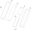
Fig. 2 is an exploded view of a mobile terminal provided in an embodiment of the present disclosure. -
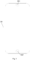
Fig. 3 is a schematic view of a cover plate provided in an embodiment of the present disclosure. -
Fig. 4 is a schematic view of a display screen provided in an embodiment of the present disclosure. -
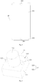
Fig. 5 is a first schematic view of a camera provided in an embodiment of the present disclosure. -
Fig. 6 is a second schematic view of a camera provided in an embodiment of the present disclosure. -
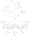
Fig. 7 is a sectional view of a receiver provided in an embodiment of the present disclosure. -
Fig. 8 is a schematic view where a receiver, a camera and a sensor assembly are mounted to a circuit board in an embodiment of the present disclosure. -
Fig. 9 is a first sectional view of the mobile terminal inFig. 1 taken along P-P direction. -
Fig. 10 is a second sectional view of the mobile terminal inFig. 1 taken along P-P direction. -
Fig. 11 is a third sectional view of the mobile terminal inFig. 1 taken along P-P direction. -
Fig. 12 is a schematic view of a receiver and camera assembly provided in an embodiment of the present disclosure. - The technical solutions of the embodiments of the present disclosure are clearly and completely described below with reference to the accompanying drawings in the embodiments of the present disclosure. Apparently, the described embodiments are only a part instead all of the embodiments of the present disclosure. All of the other embodiments derived by those ordinarily skilled in the art without creative effort based on the embodiments in the present disclosure belong to a protection scope of the present disclosure.
- In the specification, it is to be understood that terms such as "central", "longitudinal", "lateral", "length", "width", "thickness", "upper", "lower", "front", "rear", "left", "right", "vertical", "horizontal", "top", "bottom", "inner", "outer", "clockwise" and "counterclockwise", should be construed to refer to the orientation as then described or as shown in the drawings under discussion. These relative terms are for convenience of description and do not require that the present disclosure be constructed or operated in a particular orientation. In addition, terms such as "first" and "second" are used herein for purposes of description and are not intended to indicate or imply relative importance or significance. Thus, features limited by "first" and "second" are intended to indicate or imply including one or more than one these features. In the description of the present disclosure, the term "a plurality of" means two or more than two, unless specified otherwise.
- In the present disclosure, unless specified or limited otherwise, the terms "mounted", "connected", "joined", "fixed" and the like are used broadly, and may be, for example, fixed connections, detachable connections, or integral connections; may also be mechanical or electrical connections; may also be direct connections or indirect connections via intervening structures; may also be inner communications of two elements. The above terms can be understood by those skilled in the art according to specific situations.
- In the description of the present disclosure, a structure in which a first feature is "on" a second feature may include an embodiment in which the first feature directly contacts the second feature, and may also include an embodiment in which an additional feature is formed between the first feature and the second feature so that the first feature does not directly contact the second feature, unless otherwise specified. Furthermore, a first feature "on", "above", or "on top of" a second feature may include an embodiment in which the first feature is right "on", "above" or "on top of" the second feature, and may also include an embodiment in which the first feature is not right "on", "above" or "on top of" the second feature, or just means that the first feature has a sea level elevation larger than the sea level elevation of the second feature. While first feature "beneath", "below" or "on bottom of" a second feature may include an embodiment in which the first feature is right "beneath", "below" or "on bottom of" the second feature, and may also include an embodiment in which the first feature is not right "beneath", "below" or "on bottom of" the second feature, or just means that the first feature has a sea level elevation smaller than the sea level elevation of the second feature.
- The following disclosure provides many different embodiments or examples to realize different structures of the present disclosure. To simplify the disclosure of the present disclosure, components and configurations in particular examples are elaborated. Of course, they are illustrative, and are not intended to limit the present disclosure. Moreover, reference numbers and/or letters may be repeated in different examples of the present disclosure for the purpose of simplicity and clarity, which shall not be constructed to indicate the relationships among various embodiments and/or configurations. In addition, the present disclosure provides examples of various specific processes and materials, but applicability of other processes and/or utilization of other materials are conceivable for those skilled in the art.
- Referring to
Figs. 1 and2 , amobile terminal 100 includes acover plate 10, adisplay screen 20, acircuit board 30, abattery 40 and ahousing 50. - The
cover plate 10 is mounted to thedisplay screen 20 so as to cover thedisplay screen 20. Referring toFig. 3 , thecover plate 10 has a first throughhole 101 and a second throughhole 102. The first throughhole 101 and the second throughhole 102 are disposed at two ends of thecover plate 10 respectively. The first throughhole 101 can be configured to enable a receiver in themobile terminal 100 to transmit a sound signal outwardly through the first through hole. The second throughhole 102 can be configured to enable a fingerprint unit in themobile terminal 100 to acquire use finger information through the second through hole. - In some embodiments, the first through
hole 101 can be disposed at a top middle of thecover plate 10, and the second throughhole 102 can be disposed at a bottom middle of thecover plate 10. - The
cover plate 10 can be a transparent glass cover plate. In some embodiments, thecover plate 10 can be a glass cover plate made of a material such as sapphire. - The
display screen 20 is mounted to thehousing 50 so as to form a display surface of themobile terminal 100. Referring toFig. 4 , thedisplay screen 20 includes adisplay area 201 and anon-display area 202. Thedisplay area 201 is configured to display information like image and text. Thenon-display area 202 does not display information. Thenon-display area 202 can be provided with a functional assembly such as the fingerprint unit and a touch circuit. - The
display area 201 is provided with a third throughhole 203. The third throughhole 203 is aligned with the first throughhole 101 in thecover plate 10. The third throughhole 203 can be configured so that the camera in themobile terminal 100 can acquire an external image signal through the third through hole, a proximity sensor in themobile terminal 100 can emit and receive a signal through the third through hole, and the receiver in themobile terminal 100 can transmit the sound signal outwardly through the third through hole. - The
non-display area 202 is provided with a fourth throughhole 204. The fourth throughhole 204 is aligned with the second throughhole 102 in thecover plate 10. The fourth throughhole 204 can be configured so that the fingerprint unit in themobile terminal 100 can acquire the user fingerprint information through the fourth through hole. - In some embodiments, the third through
hole 203 can be disposed at a top middle of thedisplay area 201, and the fourth throughhole 204 can be disposed at a bottom middle of thenon-display area 202. - The
circuit board 30 is mounted in thehousing 50. Thecircuit board 30 can be a main board of themobile terminal 100 and functional assemblies such as the camera, the proximity sensor, and the receiver can be integrated in thecircuit board 30. Meanwhile, thedisplay screen 20 can be electrically connected to thecircuit board 30. - Referring to
Fig. 5 , thecamera 31 can be integrated in thecircuit board 30. Thecamera 31 includes abase 311 and acamera lens 312. Thecamera lens 312 is mounted to thebase 311. A contour of the base 311 can be rectangular, circular or in other shapes. A contour size of thebase 311 is larger than a contour size of thecamera lens 312, so that astep 310 can be formed at a mounting face of thecamera lens 312 and thebase 311. A step surface of thestep 310 faces thedisplay screen 20 in themobile terminal 100. - The
sensor assembly 32 is mounted to thestep 310. Thesensor assembly 32 includes asignal emitter 321 and asignal receiver 322. Thesignal emitter 321 and thesignal receiver 322 can compose the proximity sensor. Thesignal emitter 321 and thesignal receiver 322 are electrically connected to thecircuit board 30. - The
signal emitter 321 is configured to emit a signal, and thesignal receiver 322 is configured to receive a reflected signal formed by reflecting the emitted signal by an external object. Themobile terminal 100 can judge a distance state between themobile terminal 100 and the external object according to strength of the reflected signal so as to control a display state of thedisplay screen 20. - The above-mentioned signal can be a light signal such as an infrared ray, a laser and the like, and can also be other types of signals.
- The
signal emitter 321 and thesignal receiver 322 can be disposed at different sides of thecamera lens 312 along a width direction of themobile terminal 100. Thesignal emitter 321 and thesignal receiver 322 can also be disposed at different sides of thecamera lens 312 along a length direction of themobile terminal 100. - As the
camera 31 is formed with thestep 310 and hence thesensor assembly 32 can be mounted on thestep 310, it is unnecessary to provide an independent aperture for thesensor assembly 32 in themobile terminal 100. Thus, occupation of thesensor assembly 32 on the display area in the screen of themobile terminal 100 is reduced, that is, a ratio of the display area to the screen is increased. - Referring to
Fig. 6 , thesensor assembly 32 further includes an ambientlight sensor 323. The ambientlight sensor 323 is disposed around thecamera lens 312 and mounted on thestep 310. The ambientlight sensor 323 is also electrically connected to thecircuit board 30. The ambientlight sensor 323 is configured to receive an ambient light signal. Themobile terminal 100 can also adjust brightness of thedisplay screen 20 according to strength of the ambient light signal. - Referring to
Fig. 7 , thereceiver 33 can be integrated in thecircuit board 30. Thereceiver 33 can be comprised of a vibration section 33-1, a magnetic circuit section 33-2 and a supporting section 33-3. The supporting section 33-3 is formed as a casing of thereceiver 33. The magnetic circuit section 33-2 is mounted in the casing so as to form a magnetic circuit. The vibration section 33-1 is mounted above the magnetic circuit section 33-2 and produces sound through vibration. - The vibration section 33-1 includes a
diaphragm 331 and avoice coil 332. Thevoice coil 332 is disposed at a side of thediaphragm 331 and connected with thediaphragm 331. The connection between thevoice coil 332 and thediaphragm 331 can be realized by a plurality of methods. For example, thevoice coil 332 can be connected with thediaphragm 331 in an adhesive method. - The
diaphragm 331 can be a transparent diaphragm so as to allow a light signal to pass through. A shape of thediaphragm 331 matches a shape of thereceiver 33. The shape of thediaphragm 331 can be circular. - The
diaphragm 331 can be an elastic diaphragm and can vibrate up and down along a thickness direction of the diaphragm. When thediaphragm 331 vibrates, air at two sides of the diaphragm vibrates therewith so as to produce sound. - The
voice coil 332 is formed by winding a conductive wire upon an insulation frame, the wire having an insulating outer layer. The conductive wire on thevoice coil 332 is configured to be connected to an audio-frequency circuit inside themobile terminal 100. - The magnetic circuit section 33-2 includes a
permanent magnet 333, a magneticallyconductive sheet 334 and a magneticallyconductive plate 335. The magneticallyconductive sheet 334 can be disposed at a side (N pole) of thepermanent magnet 333, and the magneticallyconductive plate 335 is disposed at the other side (S pole) of thepermanent magnet 333. The magneticallyconductive sheet 334 and the magneticallyconductive plate 335 are configured to conduct a magnetic induction line emitted by thepermanent magnet 333 so as to form a closed magnetic circuit. The magnetic induction line emitted by the N pole of thepermanent magnet 333 passes through the magneticallyconductive sheet 334, then passes through the magneticallyconductive plate 335, and finally enters the S pole of thepermanent magnet 333, so as to form a closed loop circuit. The magneticallyconductive sheet 334 can be an iron sheet, and the magneticallyconductive plate 335 can be a thin iron plate. The shapes of the magneticallyconductive sheet 334 and the magneticallyconductive plate 335 can be square, rectangular, or circular. The magneticallyconductive sheet 334, thepermanent magnet 333, and the magneticallyconductive plate 335 can be fastened in the adhesive manner. - The
permanent magnet 333 has anaperture 330, the magneticallyconductive sheet 334 is provided with anaperture 340, and the magneticallyconductive plate 335 has anaperture 350. Theaperture 340 and theaperture 350 are both aligned with theaperture 330. - The
transparent diaphragm 331, theaperture 340, theaperture 330 and theaperture 350 together form a light signal passage so as to allow the light signal to pass through. - In some embodiments, the
permanent magnet 333 is a nanometer permanent magnet. That is, permanent magnetic material particles are uniformly coated with a layer of soft magnetic material by nanotechnology, or the permanent magnetic material and the soft magnetic material are combined together by a chemical process such as a replacement reaction, so as to obtain permanent magnetic nanoparticles. Then, the nanometer permanent magnet is manufactured by techniques such as high-pressure molding or high-temperature sintering. The nanometer permanent magnet has higher magnetic induction intensity inside relative to an ordinary Nd-Fe-B permanent magnet. Thus, with the same volume of the permanent magnet, the receiver adopting the nanometer permanent magnet has a higher sound pressure level. - In some embodiments, the magnetically
conductive plate 335 is U-shaped. Thepermanent magnet 333 and the magneticallyconductive sheet 334 are disposed at a bottom of the U shape of the magneticallyconductive plate 335. Extension portions at two sides of the magneticallyconductive plate 335 extend upwards to two sides of thepermanent magnet 333 and the magneticallyconductive sheet 334. A gap is formed between each of the side extension portions of the magneticallyconductive plate 335 and the corresponding side of two sides of thepermanent magnet 333 and the magneticallyconductive sheet 334, and thevoice coil 332 is disposed in the gap. - The supporting section 33-3 includes a
support 336 and aprotection cover 337. Thesupport 336 is formed in an annular shape. A peripheral protrusion is provided at a periphery of an end of thesupport 336. Theprotection cover 337 is formed in an annular shape. An aperture can be provided in a center of theprotection cover 337, so that the sound produced by thediaphragm 331 can be transmitted outwardly. A section of theprotection cover 337 exhibits a reversed L shape. A periphery of theprotection cover 337 is provided with a peripheral recess. With the peripheral protrusion of thesupport 336 fitted with the peripheral recess of theprotection cover 337, theprotection cover 337 is mounted to thesupport 336. Thediaphragm 331 is mounted to thesupport 336 by means of a mounting portion at an edge of the diaphragm. The mounting portion at the edge of thediaphragm 331 can be mounted to thesupport 336 in the adhesive method. - In some embodiments, the
support 336 is made of nanomaterial. Theprotection cover 337 can also be made of nanomaterial. Both of thesupport 336 and theprotection cover 337 can be integrally formed by the nanomaterial through injection molding. Thesupport 336 and theprotection cover 337 made of nanomaterial have higher strength, which can improve mechanical reliability of thereceiver 33. - Referring to
Fig. 8 , in themobile terminal 100, thecamera 31 and thereceiver 33 are both mounted to thecircuit board 30. Thecamera 31 is aligned with thelight signal passage 34 of thereceiver 33. Thesensor assembly 32 can be mounted on the step of thecamera 31. Meanwhile, asensor assembly 32 is electrically connected to thecircuit board 30. Thesensor assembly 32 includes thesignal emitter 321 and thesignal receiver 322. Thesignal emitter 321 and thesignal receiver 322 can be disposed at two sides of the camera lens of thecamera 31 respectively. - Reference is still made to
Figs. 1 and2 . - The
battery 40 is mounted inside thehousing 50 and configured to provide electrical energy for themobile terminal 100. - The
housing 50 is configured to form an external contour of themobile terminal 100. Thehousing 50 can be made of plastic or metal. Thehousing 50 can be formed integrally. - Referring to
Fig. 9, Fig. 9 is a section view of the mobile terminal illustrated inFig. 1 taken along P-P direction. Thecover plate 10 is mounted to thehousing 50. Thecover plate 10 has anaperture 110. Thedisplay screen 20 is also mouthed to thehousing 50. Thedisplay screen 20 has an aperture 210 (namely the above-mentioned third throughhole 203, there is no strict difference between terms "aperture" and "through hole" in the descriptions). Thecover plate 10 covers thedisplay screen 20. Theaperture 210 is aligned with theaperture 110. Thecircuit board 30 is mounted in thehousing 50. - The
camera 31 and thereceiver 33 are mounted to thecircuit board 30. Thereceiver 33 is disposed between thecamera 31 and thedisplay screen 20. Thereceiver 33 is aligned with theaperture 210 and theaperture 110 so that thereceiver 33 can transmit the sound signal outwardly through theaperture 210 and theaperture 110. Thereceiver 33 has thelight signal passage 34. Thecamera 31 is aligned with thelight signal passage 34 so that thecamera 31 can acquire the light signal from the outside through thelight signal passage 34, theaperture 210 and theaperture 110. - As the
camera 31 is disposed below thereceiver 33 along the thickness direction of themobile terminal 100, it is unnecessary to provide independent apertures for thecamera 31 and thereceiver 33 in thedisplay screen 20. Thus, occupation of the apertures in thedisplay screen 20 relative to the display area is reduced, and the ratio of the display area to the screen of themobile terminal 100 is increased. - In some embodiments, as illustrated in
Fig. 10 , thesensor assembly 32 can be mounted to thecircuit board 30. Thesensor assembly 32 is aligned with thelight signal passage 34 in thereceiver 33 so as to allow thesensor assembly 32 to receive and/or emit signals through thelight signal passage 34, theaperture 210 and theaperture 110. Thesensor assembly 32 includes thesignal emitter 321 and thesignal receiver 322. Thesignal emitter 321 and thesignal receiver 322 can be disposed at two sides of thecamera 31 respectively. - In some embodiments, the
sensor assembly 32 can further include the ambient light sensor. The ambient light sensor can be disposed around thecamera 31. - In some embodiments, as illustrated in
Fig. 11 , thecamera 31 is formed with thestep 310. The step surface of thestep 310 faces thedisplay screen 20, and thesensor assembly 32 can be disposed on thestep 310. Thesensor assembly 32 includes thesignal emitter 321 and thesignal receiver 322. Thesignal emitter 321 and thesignal receiver 322 can be disposed at two sides of the camera lens of thecamera 31 respectively. - In some embodiments, the
sensor assembly 32 can further include the ambient light sensor. The ambient light sensor can be disposed on thestep 310 and around the camera lens of thecamera 31. - As illustrated in
Fig. 12 , a receiver and camera assembly configured to be mounted in a mobile terminal is provided in embodiments of the present disclosure, including areceiver 33, acamera 31. Thereceiver 33 has alight signal passage 34, and thecamera 31 is aligned with thelight signal passage 34. Thereceiver 33 and thecamera 31 can be integrated. Specifically, thereceiver 33 and thecamera 31 can be mounted to a mountingplate 35. The mountingplate 35 can be configured to be connected to a circuit board of the mobile terminal. - The mobile terminal provided by the embodiment of the present disclosure is described in detail above, and specific examples are used herein to describe the principle and embodiments of the present disclosure. The description of the foregoing embodiments is merely intended to help understand the present disclosure. Meanwhile, those skilled in the art can make modifications to the specific embodiments and application scope according to the idea of the present disclosure. To sum up, the contents of the description should not be construed as limiting the present disclosure.
Claims (14)
Applications Claiming Priority (1)
| Application Number | Priority Date | Filing Date | Title |
|---|---|---|---|
| CN201710132219.0A CN106936954B (en) | 2017-03-07 | 2017-03-07 | Mobile terminal |
Publications (2)
| Publication Number | Publication Date |
|---|---|
| EP3373564A1 true EP3373564A1 (en) | 2018-09-12 |
| EP3373564B1 EP3373564B1 (en) | 2020-02-26 |
Family
ID=59423458
Family Applications (1)
| Application Number | Title | Priority Date | Filing Date |
|---|---|---|---|
| EP18150952.2A Active EP3373564B1 (en) | 2017-03-07 | 2018-01-10 | Mobile terminal, receiver for a mobile terminal, receiver and camera assembly for a mobile terminal |
Country Status (9)
| Country | Link |
|---|---|
| US (2) | US10291756B2 (en) |
| EP (1) | EP3373564B1 (en) |
| JP (1) | JP6783393B2 (en) |
| CN (2) | CN106936954B (en) |
| AU (1) | AU2018229784B2 (en) |
| ES (1) | ES2790250T3 (en) |
| SG (1) | SG11201906191TA (en) |
| TW (1) | TWI658719B (en) |
| WO (1) | WO2018161720A1 (en) |
Cited By (4)
| Publication number | Priority date | Publication date | Assignee | Title |
|---|---|---|---|---|
| CN109302569A (en) * | 2018-09-27 | 2019-02-01 | 维沃移动通信有限公司 | Image imaging method and device for mobile terminal |
| EP3480852A3 (en) * | 2017-11-03 | 2019-07-17 | Shih-Hsien Tseng | Pixel unit, pixel array, multimedia device and manufacturing methods thereof |
| US10930631B2 (en) | 2017-11-03 | 2021-02-23 | Shih-Hsien Tseng | Display apparatus, pixel array and manufacturing method thereof |
| US20220191352A1 (en) * | 2020-12-16 | 2022-06-16 | Samsung Electronics Co., Ltd. | Electronic device |
Families Citing this family (50)
| Publication number | Priority date | Publication date | Assignee | Title |
|---|---|---|---|---|
| CN106657485B (en) | 2017-03-07 | 2020-05-12 | Oppo广东移动通信有限公司 | mobile terminal |
| CN106936954B (en) | 2017-03-07 | 2020-05-12 | Oppo广东移动通信有限公司 | Mobile terminal |
| KR102167928B1 (en) * | 2017-03-14 | 2020-10-20 | 엘지전자 주식회사 | Mobile terminal |
| CN107247356A (en) * | 2017-07-31 | 2017-10-13 | 广东欧珀移动通信有限公司 | Display panel and electronic equipment |
| US20190037063A1 (en) * | 2017-07-31 | 2019-01-31 | Guangdong Oppo Mobile Telecommunications Corp., Ltd. | Display panel and electronic device |
| CN107562122B (en) * | 2017-08-11 | 2019-04-30 | Oppo广东移动通信有限公司 | Display assembly and terminal |
| CN107331314A (en) | 2017-08-23 | 2017-11-07 | 京东方科技集团股份有限公司 | a display device |
| CN107479238A (en) * | 2017-08-31 | 2017-12-15 | 广东欧珀移动通信有限公司 | Array substrate, self-capacitive touch display panel and electronic equipment |
| CN114363441B (en) * | 2017-09-30 | 2025-08-22 | 华为技术有限公司 | Terminal device and sound output device |
| CN107786696B (en) * | 2017-12-13 | 2024-06-18 | 京东方科技集团股份有限公司 | Display screen and mobile terminal |
| CN109936646A (en) * | 2017-12-15 | 2019-06-25 | 广东欧珀移动通信有限公司 | Electronic equipment |
| US10917506B2 (en) | 2018-02-05 | 2021-02-09 | Guangdong Oppo Mobile Telecommunications Corp., Ltd. | Terminal display assembly and mobile terminal |
| US10620665B2 (en) | 2018-02-05 | 2020-04-14 | Guangdong Oppo Mobile Telecommunications Corp., Lt | Terminal display assembly and mobile terminal |
| EP3547019B1 (en) | 2018-03-30 | 2021-10-27 | Guangdong Oppo Mobile Telecommunications Corp., Ltd. | Display assembly and mobile terminal |
| EP3547074B1 (en) | 2018-03-30 | 2021-03-10 | Guangdong Oppo Mobile Telecommunications Corp., Ltd. | Display screen, terminal display screen assembly, and mobile terminal |
| US10623542B2 (en) | 2018-03-30 | 2020-04-14 | Guangdong Oppo Mobile Telecommunications Corp., Ltd. | Display assembly and mobile terminal |
| WO2019184579A1 (en) | 2018-03-30 | 2019-10-03 | Guangdong Oppo Mobile Telecommunications Corp. , Ltd. | Display screen, terminal display screen assembly, and mobile terminal |
| CN108769300B (en) * | 2018-04-20 | 2020-04-17 | 珠海市魅族科技有限公司 | Terminal device |
| CN208433994U (en) | 2018-04-26 | 2019-01-25 | Oppo广东移动通信有限公司 | Terminal display assembly and mobile terminal |
| CN208401902U (en) | 2018-04-26 | 2019-01-18 | Oppo广东移动通信有限公司 | terminal display screen component and mobile terminal |
| CN208158661U (en) | 2018-04-26 | 2018-11-27 | Oppo广东移动通信有限公司 | terminal display screen component and mobile terminal |
| US11402669B2 (en) | 2018-04-27 | 2022-08-02 | Apple Inc. | Housing surface with tactile friction features |
| CN108777727B (en) * | 2018-05-29 | 2020-05-29 | 维沃移动通信有限公司 | A circuit control method and mobile terminal |
| CN108769328B (en) * | 2018-05-29 | 2020-02-11 | 维沃移动通信有限公司 | Combined device of receiver and camera and mobile terminal |
| CN108769312B (en) * | 2018-05-29 | 2021-01-08 | 维沃移动通信有限公司 | Mobile terminal's apron structure and mobile terminal |
| US10694010B2 (en) * | 2018-07-06 | 2020-06-23 | Apple Inc. | Cover sheet and incorporated lens for a camera of an electronic device |
| EP3820122B1 (en) * | 2018-07-16 | 2022-02-02 | Guangdong Oppo Mobile Telecommunications Corp., Ltd. | Electronic device |
| CN208795975U (en) * | 2018-07-18 | 2019-04-26 | 深圳市宝明科技股份有限公司 | A kind of backlight with through-hole |
| US11112827B2 (en) | 2018-07-20 | 2021-09-07 | Apple Inc. | Electronic device with glass housing member |
| CN110798549B (en) * | 2018-08-01 | 2021-04-27 | Oppo广东移动通信有限公司 | Electronic device |
| CN110798563A (en) * | 2018-08-01 | 2020-02-14 | Oppo广东移动通信有限公司 | Display panel assembly and electronic device having the same |
| CN111262966B (en) * | 2018-11-30 | 2021-08-31 | 北京小米移动软件有限公司 | Electronic equipment |
| US11691912B2 (en) | 2018-12-18 | 2023-07-04 | Apple Inc. | Chemically strengthened and textured glass housing member |
| KR102600941B1 (en) * | 2019-02-01 | 2023-11-13 | 삼성전자주식회사 | Electronic device including display |
| US11199929B2 (en) | 2019-03-21 | 2021-12-14 | Apple Inc. | Antireflective treatment for textured enclosure components |
| KR102771506B1 (en) * | 2019-04-12 | 2025-02-21 | 삼성디스플레이 주식회사 | Display device |
| CN110166600B (en) * | 2019-05-27 | 2020-12-04 | Oppo广东移动通信有限公司 | Electronic device and control method thereof |
| US11372137B2 (en) | 2019-05-29 | 2022-06-28 | Apple Inc. | Textured cover assemblies for display applications |
| US11192823B2 (en) | 2019-06-05 | 2021-12-07 | Apple Inc. | Electronic devices including laser-textured glass cover members |
| US10827635B1 (en) | 2019-06-05 | 2020-11-03 | Apple Inc. | Electronic device enclosure having a textured glass component |
| US11109500B2 (en) | 2019-06-05 | 2021-08-31 | Apple Inc. | Textured glass component for an electronic device enclosure |
| WO2021000196A1 (en) * | 2019-06-30 | 2021-01-07 | 瑞声声学科技(深圳)有限公司 | Antenna module for use in folding screen terminal and terminal |
| CN110312020A (en) * | 2019-07-19 | 2019-10-08 | 西安易朴通讯技术有限公司 | A kind of terminal |
| CN110650225A (en) * | 2019-09-17 | 2020-01-03 | 歌尔科技有限公司 | Acoustic and electronic equipment |
| CN111225305B (en) * | 2020-01-15 | 2022-01-07 | Oppo广东移动通信有限公司 | Electronic device |
| KR102798635B1 (en) * | 2020-02-11 | 2025-04-21 | 삼성디스플레이 주식회사 | Convertivble-type electronic apparatus |
| US11897809B2 (en) | 2020-09-02 | 2024-02-13 | Apple Inc. | Electronic devices with textured glass and glass ceramic components |
| CN112968984B (en) * | 2021-01-29 | 2022-09-23 | 华为技术有限公司 | Terminal device |
| CN113114826A (en) * | 2021-05-21 | 2021-07-13 | 维沃移动通信有限公司 | Electronic equipment |
| TWI832085B (en) * | 2021-09-07 | 2024-02-11 | 群邁通訊股份有限公司 | Mobile device |
Citations (3)
| Publication number | Priority date | Publication date | Assignee | Title |
|---|---|---|---|---|
| US20100165182A1 (en) * | 2006-08-08 | 2010-07-01 | Nxp, B.V. | Combination device of speaker and camera optical system |
| US20130094126A1 (en) * | 2011-10-14 | 2013-04-18 | Benjamin M. Rappoport | Electronic Devices Having Displays with Openings |
| CN106453726A (en) * | 2016-12-06 | 2017-02-22 | 广东欧珀移动通信有限公司 | Sensor component and terminal |
Family Cites Families (36)
| Publication number | Priority date | Publication date | Assignee | Title |
|---|---|---|---|---|
| US7388619B2 (en) * | 2003-12-11 | 2008-06-17 | Sony Ericsson Mobile Communications Ab | Mobile device with a combination camera and loudspeaker |
| JP4411059B2 (en) * | 2003-12-12 | 2010-02-10 | キヤノン株式会社 | Display device with camera, communication device, and communication system |
| JP4585409B2 (en) | 2005-08-24 | 2010-11-24 | 株式会社東芝 | Small camera module |
| KR20070104010A (en) * | 2006-04-21 | 2007-10-25 | 엘지이노텍 주식회사 | Camera module and portable terminal having same |
| TWI411910B (en) | 2008-05-29 | 2013-10-11 | Htc Corp | Handheld device and its power saving method |
| KR20090125547A (en) | 2008-06-02 | 2009-12-07 | (주)나노지피 | Camera device for wireless communication terminal with auto focusing |
| US8456586B2 (en) * | 2009-06-11 | 2013-06-04 | Apple Inc. | Portable computer display structures |
| US8913738B2 (en) | 2009-06-30 | 2014-12-16 | Nokia Corporation | Apparatus with wideband earpiece response |
| KR101711830B1 (en) | 2010-06-03 | 2017-03-03 | 엘지전자 주식회사 | Mobile terminal |
| JP2013239788A (en) * | 2012-05-11 | 2013-11-28 | Sharp Corp | Portable terminal |
| CN103841222A (en) | 2012-11-20 | 2014-06-04 | 安谷通信技术(深圳)有限公司 | Mobile phone with full-screen display function |
| JP2014183396A (en) * | 2013-03-18 | 2014-09-29 | Sharp Corp | Image pickup device and electronic apparatus |
| US9165444B2 (en) | 2013-07-26 | 2015-10-20 | SkyBell Technologies, Inc. | Light socket cameras |
| KR102168200B1 (en) * | 2013-09-17 | 2020-10-20 | 삼성전자주식회사 | Electronic device without front case frame |
| KR102107114B1 (en) | 2013-10-30 | 2020-05-06 | 엘지전자 주식회사 | Mobile terminal |
| CN104793695A (en) | 2014-01-17 | 2015-07-22 | 宏碁股份有限公司 | Hand-held electronic device |
| CN203666511U (en) | 2014-01-23 | 2014-06-25 | 金陵科技学院 | Automobile side view camera device |
| CN204119279U (en) * | 2014-06-18 | 2015-01-21 | 锤子科技(北京)有限公司 | A kind of mobile terminal |
| CN104539833A (en) * | 2015-01-07 | 2015-04-22 | 京东方科技集团股份有限公司 | Electronic equipment |
| CN204334759U (en) | 2015-01-24 | 2015-05-13 | 江苏金成光电科技有限公司 | A kind of band light sensation mobile phone camera |
| CN104601763A (en) | 2015-02-25 | 2015-05-06 | 胡伟 | Cellphone |
| CN104950419B (en) | 2015-07-06 | 2017-09-29 | 南昌欧菲光电技术有限公司 | Camera module |
| US9807211B2 (en) * | 2015-07-19 | 2017-10-31 | Otter Products, Llc | Protective modular case for electronic device |
| CN205610701U (en) * | 2016-04-07 | 2016-09-28 | 广东欧珀移动通信有限公司 | mobile terminal |
| CN205453887U (en) * | 2016-04-09 | 2016-08-10 | 兰州交通大学 | Seizure camera that accuracy is high |
| CN105791651B (en) | 2016-04-14 | 2019-11-12 | 唐小川 | Camera module and picture pick-up device with flash lamp |
| CN205647713U (en) | 2016-05-04 | 2016-10-12 | 江阴新晟电子有限公司 | Take iris recognition function's two megapixel cell -phone camera modules |
| CN205726042U (en) | 2016-06-02 | 2016-11-23 | 奉化波导软件有限公司 | Camera structure and there is the mobile terminal of this camera structure |
| CN105991807A (en) * | 2016-06-16 | 2016-10-05 | 珠海市魅族科技有限公司 | Receiver equipment used for mobile terminal and mobile terminal |
| CN106331235A (en) | 2016-09-12 | 2017-01-11 | 努比亚技术有限公司 | Mobile terminal main board, mobile terminal main board setting method, and mobile terminal |
| CN106371187A (en) | 2016-10-28 | 2017-02-01 | 圆融健康科技(深圳)有限公司 | Camera lens cone, camera module and mobile phone |
| CN106453722A (en) * | 2016-11-30 | 2017-02-22 | 努比亚技术有限公司 | Telephone receiver device and mobile terminal |
| CN106453725B (en) * | 2016-12-06 | 2023-04-07 | Oppo广东移动通信有限公司 | Terminal device |
| CN106453724A (en) * | 2016-12-06 | 2017-02-22 | 广东欧珀移动通信有限公司 | Panel, sensor assembly and mobile terminal |
| CN106936954B (en) * | 2017-03-07 | 2020-05-12 | Oppo广东移动通信有限公司 | Mobile terminal |
| CN106657485B (en) | 2017-03-07 | 2020-05-12 | Oppo广东移动通信有限公司 | mobile terminal |
-
2017
- 2017-03-07 CN CN201710132219.0A patent/CN106936954B/en not_active Expired - Fee Related
- 2017-03-07 CN CN202010266205.XA patent/CN111447309B/en not_active Expired - Fee Related
- 2017-12-15 TW TW106144061A patent/TWI658719B/en active
-
2018
- 2018-01-09 SG SG11201906191TA patent/SG11201906191TA/en unknown
- 2018-01-09 AU AU2018229784A patent/AU2018229784B2/en not_active Ceased
- 2018-01-09 WO PCT/CN2018/071962 patent/WO2018161720A1/en not_active Ceased
- 2018-01-09 JP JP2019534886A patent/JP6783393B2/en not_active Expired - Fee Related
- 2018-01-10 US US15/867,256 patent/US10291756B2/en active Active
- 2018-01-10 EP EP18150952.2A patent/EP3373564B1/en active Active
- 2018-01-10 ES ES18150952T patent/ES2790250T3/en active Active
-
2019
- 2019-04-02 US US16/373,613 patent/US10834245B2/en not_active Expired - Fee Related
Patent Citations (3)
| Publication number | Priority date | Publication date | Assignee | Title |
|---|---|---|---|---|
| US20100165182A1 (en) * | 2006-08-08 | 2010-07-01 | Nxp, B.V. | Combination device of speaker and camera optical system |
| US20130094126A1 (en) * | 2011-10-14 | 2013-04-18 | Benjamin M. Rappoport | Electronic Devices Having Displays with Openings |
| CN106453726A (en) * | 2016-12-06 | 2017-02-22 | 广东欧珀移动通信有限公司 | Sensor component and terminal |
Cited By (7)
| Publication number | Priority date | Publication date | Assignee | Title |
|---|---|---|---|---|
| EP3480852A3 (en) * | 2017-11-03 | 2019-07-17 | Shih-Hsien Tseng | Pixel unit, pixel array, multimedia device and manufacturing methods thereof |
| US10847500B2 (en) | 2017-11-03 | 2020-11-24 | Shih-Hsien Tseng | Pixel unit, pixel array, multimedia device and manufacturing method thereof |
| US10930631B2 (en) | 2017-11-03 | 2021-02-23 | Shih-Hsien Tseng | Display apparatus, pixel array and manufacturing method thereof |
| US11056469B2 (en) | 2017-11-03 | 2021-07-06 | Shih-Hsien Tseng | Multimedia device having a pixel array and method for manufacturing the multimedia device |
| CN109302569A (en) * | 2018-09-27 | 2019-02-01 | 维沃移动通信有限公司 | Image imaging method and device for mobile terminal |
| US20220191352A1 (en) * | 2020-12-16 | 2022-06-16 | Samsung Electronics Co., Ltd. | Electronic device |
| US11895379B2 (en) * | 2020-12-16 | 2024-02-06 | Samsung Electronics Co., Ltd | Electronic device |
Also Published As
| Publication number | Publication date |
|---|---|
| JP6783393B2 (en) | 2020-11-11 |
| ES2790250T3 (en) | 2020-10-27 |
| CN111447309A (en) | 2020-07-24 |
| SG11201906191TA (en) | 2019-08-27 |
| US10291756B2 (en) | 2019-05-14 |
| TWI658719B (en) | 2019-05-01 |
| US10834245B2 (en) | 2020-11-10 |
| CN106936954B (en) | 2020-05-12 |
| US20190230204A1 (en) | 2019-07-25 |
| TW201834436A (en) | 2018-09-16 |
| JP2020503767A (en) | 2020-01-30 |
| EP3373564B1 (en) | 2020-02-26 |
| US20180262602A1 (en) | 2018-09-13 |
| AU2018229784A1 (en) | 2019-07-18 |
| CN111447309B (en) | 2022-04-29 |
| WO2018161720A1 (en) | 2018-09-13 |
| AU2018229784B2 (en) | 2020-07-16 |
| CN106936954A (en) | 2017-07-07 |
Similar Documents
| Publication | Publication Date | Title |
|---|---|---|
| US10291756B2 (en) | Mobile terminal, receiver for a mobile terminal, receiver and camera assembly for a mobile terminal | |
| CN106657485B (en) | mobile terminal | |
| CN106303858B (en) | A kind of loudspeaker and terminal device | |
| KR102788285B1 (en) | Electronic device including speaker unit | |
| CN114363778B (en) | Sound producing device and electronic equipment | |
| US11302861B2 (en) | Hybrid actuator having a flexible printed circuit board for applying an electric current to a piezoelectric element and a coil inside a housing of the hybrid actuator | |
| CN107547997B (en) | Circuit board assemblies and electronic equipment | |
| CN117641208A (en) | Sound producing device and electronic equipment | |
| JP2009278214A (en) | Electroacoustic transducer | |
| US20130287244A1 (en) | Loudspeaker with reinforced frame | |
| US10244326B2 (en) | Miniature sounder | |
| CN114513728B (en) | Electronic equipment | |
| CN114501249B (en) | Sound producing device and electronic equipment | |
| CN114501251B (en) | Sound producing device and electronic equipment | |
| CN107404696A (en) | A kind of assembly method of vibrating mechanism, receiver and receiver | |
| KR20240123720A (en) | Electronic device including speaker module | |
| HK1236704A1 (en) | Mobile terminal | |
| HK1236704A (en) | Mobile terminal | |
| US20200059730A1 (en) | Speaker | |
| HK1236704B (en) | Mobile terminal | |
| CN114501250B (en) | Electronic equipment | |
| KR102127981B1 (en) | Vibration motor | |
| CN207075064U (en) | Loudspeaker enclosure | |
| JP2005080044A (en) | Flat board loudspeaker unit and electric apparatus with the unit |
Legal Events
| Date | Code | Title | Description |
|---|---|---|---|
| PUAI | Public reference made under article 153(3) epc to a published international application that has entered the european phase |
Free format text: ORIGINAL CODE: 0009012 |
|
| STAA | Information on the status of an ep patent application or granted ep patent |
Free format text: STATUS: REQUEST FOR EXAMINATION WAS MADE |
|
| 17P | Request for examination filed |
Effective date: 20180723 |
|
| AK | Designated contracting states |
Kind code of ref document: A1 Designated state(s): AL AT BE BG CH CY CZ DE DK EE ES FI FR GB GR HR HU IE IS IT LI LT LU LV MC MK MT NL NO PL PT RO RS SE SI SK SM TR |
|
| AX | Request for extension of the european patent |
Extension state: BA ME |
|
| STAA | Information on the status of an ep patent application or granted ep patent |
Free format text: STATUS: EXAMINATION IS IN PROGRESS |
|
| 17Q | First examination report despatched |
Effective date: 20181115 |
|
| GRAP | Despatch of communication of intention to grant a patent |
Free format text: ORIGINAL CODE: EPIDOSNIGR1 |
|
| STAA | Information on the status of an ep patent application or granted ep patent |
Free format text: STATUS: GRANT OF PATENT IS INTENDED |
|
| INTG | Intention to grant announced |
Effective date: 20191031 |
|
| RAP1 | Party data changed (applicant data changed or rights of an application transferred) |
Owner name: GUANGDONG OPPO MOBILE TELECOMMUNICATIONS CORP., LT |
|
| GRAS | Grant fee paid |
Free format text: ORIGINAL CODE: EPIDOSNIGR3 |
|
| GRAA | (expected) grant |
Free format text: ORIGINAL CODE: 0009210 |
|
| STAA | Information on the status of an ep patent application or granted ep patent |
Free format text: STATUS: THE PATENT HAS BEEN GRANTED |
|
| AK | Designated contracting states |
Kind code of ref document: B1 Designated state(s): AL AT BE BG CH CY CZ DE DK EE ES FI FR GB GR HR HU IE IS IT LI LT LU LV MC MK MT NL NO PL PT RO RS SE SI SK SM TR |
|
| REG | Reference to a national code |
Ref country code: GB Ref legal event code: FG4D |
|
| REG | Reference to a national code |
Ref country code: CH Ref legal event code: EP |
|
| REG | Reference to a national code |
Ref country code: AT Ref legal event code: REF Ref document number: 1239067 Country of ref document: AT Kind code of ref document: T Effective date: 20200315 |
|
| REG | Reference to a national code |
Ref country code: IE Ref legal event code: FG4D |
|
| REG | Reference to a national code |
Ref country code: DE Ref legal event code: R096 Ref document number: 602018002572 Country of ref document: DE |
|
| REG | Reference to a national code |
Ref country code: NL Ref legal event code: FP |
|
| PG25 | Lapsed in a contracting state [announced via postgrant information from national office to epo] |
Ref country code: NO Free format text: LAPSE BECAUSE OF FAILURE TO SUBMIT A TRANSLATION OF THE DESCRIPTION OR TO PAY THE FEE WITHIN THE PRESCRIBED TIME-LIMIT Effective date: 20200526 Ref country code: FI Free format text: LAPSE BECAUSE OF FAILURE TO SUBMIT A TRANSLATION OF THE DESCRIPTION OR TO PAY THE FEE WITHIN THE PRESCRIBED TIME-LIMIT Effective date: 20200226 Ref country code: RS Free format text: LAPSE BECAUSE OF FAILURE TO SUBMIT A TRANSLATION OF THE DESCRIPTION OR TO PAY THE FEE WITHIN THE PRESCRIBED TIME-LIMIT Effective date: 20200226 |
|
| REG | Reference to a national code |
Ref country code: LT Ref legal event code: MG4D |
|
| PG25 | Lapsed in a contracting state [announced via postgrant information from national office to epo] |
Ref country code: HR Free format text: LAPSE BECAUSE OF FAILURE TO SUBMIT A TRANSLATION OF THE DESCRIPTION OR TO PAY THE FEE WITHIN THE PRESCRIBED TIME-LIMIT Effective date: 20200226 Ref country code: GR Free format text: LAPSE BECAUSE OF FAILURE TO SUBMIT A TRANSLATION OF THE DESCRIPTION OR TO PAY THE FEE WITHIN THE PRESCRIBED TIME-LIMIT Effective date: 20200527 Ref country code: IS Free format text: LAPSE BECAUSE OF FAILURE TO SUBMIT A TRANSLATION OF THE DESCRIPTION OR TO PAY THE FEE WITHIN THE PRESCRIBED TIME-LIMIT Effective date: 20200626 Ref country code: BG Free format text: LAPSE BECAUSE OF FAILURE TO SUBMIT A TRANSLATION OF THE DESCRIPTION OR TO PAY THE FEE WITHIN THE PRESCRIBED TIME-LIMIT Effective date: 20200526 Ref country code: LV Free format text: LAPSE BECAUSE OF FAILURE TO SUBMIT A TRANSLATION OF THE DESCRIPTION OR TO PAY THE FEE WITHIN THE PRESCRIBED TIME-LIMIT Effective date: 20200226 Ref country code: SE Free format text: LAPSE BECAUSE OF FAILURE TO SUBMIT A TRANSLATION OF THE DESCRIPTION OR TO PAY THE FEE WITHIN THE PRESCRIBED TIME-LIMIT Effective date: 20200226 |
|
| REG | Reference to a national code |
Ref country code: ES Ref legal event code: FG2A Ref document number: 2790250 Country of ref document: ES Kind code of ref document: T3 Effective date: 20201027 |
|
| PG25 | Lapsed in a contracting state [announced via postgrant information from national office to epo] |
Ref country code: LT Free format text: LAPSE BECAUSE OF FAILURE TO SUBMIT A TRANSLATION OF THE DESCRIPTION OR TO PAY THE FEE WITHIN THE PRESCRIBED TIME-LIMIT Effective date: 20200226 Ref country code: PT Free format text: LAPSE BECAUSE OF FAILURE TO SUBMIT A TRANSLATION OF THE DESCRIPTION OR TO PAY THE FEE WITHIN THE PRESCRIBED TIME-LIMIT Effective date: 20200719 Ref country code: RO Free format text: LAPSE BECAUSE OF FAILURE TO SUBMIT A TRANSLATION OF THE DESCRIPTION OR TO PAY THE FEE WITHIN THE PRESCRIBED TIME-LIMIT Effective date: 20200226 Ref country code: CZ Free format text: LAPSE BECAUSE OF FAILURE TO SUBMIT A TRANSLATION OF THE DESCRIPTION OR TO PAY THE FEE WITHIN THE PRESCRIBED TIME-LIMIT Effective date: 20200226 Ref country code: DK Free format text: LAPSE BECAUSE OF FAILURE TO SUBMIT A TRANSLATION OF THE DESCRIPTION OR TO PAY THE FEE WITHIN THE PRESCRIBED TIME-LIMIT Effective date: 20200226 Ref country code: SM Free format text: LAPSE BECAUSE OF FAILURE TO SUBMIT A TRANSLATION OF THE DESCRIPTION OR TO PAY THE FEE WITHIN THE PRESCRIBED TIME-LIMIT Effective date: 20200226 Ref country code: EE Free format text: LAPSE BECAUSE OF FAILURE TO SUBMIT A TRANSLATION OF THE DESCRIPTION OR TO PAY THE FEE WITHIN THE PRESCRIBED TIME-LIMIT Effective date: 20200226 Ref country code: SK Free format text: LAPSE BECAUSE OF FAILURE TO SUBMIT A TRANSLATION OF THE DESCRIPTION OR TO PAY THE FEE WITHIN THE PRESCRIBED TIME-LIMIT Effective date: 20200226 |
|
| REG | Reference to a national code |
Ref country code: AT Ref legal event code: MK05 Ref document number: 1239067 Country of ref document: AT Kind code of ref document: T Effective date: 20200226 |
|
| REG | Reference to a national code |
Ref country code: DE Ref legal event code: R097 Ref document number: 602018002572 Country of ref document: DE |
|
| PLBE | No opposition filed within time limit |
Free format text: ORIGINAL CODE: 0009261 |
|
| STAA | Information on the status of an ep patent application or granted ep patent |
Free format text: STATUS: NO OPPOSITION FILED WITHIN TIME LIMIT |
|
| PG25 | Lapsed in a contracting state [announced via postgrant information from national office to epo] |
Ref country code: AT Free format text: LAPSE BECAUSE OF FAILURE TO SUBMIT A TRANSLATION OF THE DESCRIPTION OR TO PAY THE FEE WITHIN THE PRESCRIBED TIME-LIMIT Effective date: 20200226 |
|
| 26N | No opposition filed |
Effective date: 20201127 |
|
| PG25 | Lapsed in a contracting state [announced via postgrant information from national office to epo] |
Ref country code: PL Free format text: LAPSE BECAUSE OF FAILURE TO SUBMIT A TRANSLATION OF THE DESCRIPTION OR TO PAY THE FEE WITHIN THE PRESCRIBED TIME-LIMIT Effective date: 20200226 Ref country code: SI Free format text: LAPSE BECAUSE OF FAILURE TO SUBMIT A TRANSLATION OF THE DESCRIPTION OR TO PAY THE FEE WITHIN THE PRESCRIBED TIME-LIMIT Effective date: 20200226 |
|
| PG25 | Lapsed in a contracting state [announced via postgrant information from national office to epo] |
Ref country code: MC Free format text: LAPSE BECAUSE OF FAILURE TO SUBMIT A TRANSLATION OF THE DESCRIPTION OR TO PAY THE FEE WITHIN THE PRESCRIBED TIME-LIMIT Effective date: 20200226 |
|
| REG | Reference to a national code |
Ref country code: CH Ref legal event code: PL |
|
| PG25 | Lapsed in a contracting state [announced via postgrant information from national office to epo] |
Ref country code: LU Free format text: LAPSE BECAUSE OF NON-PAYMENT OF DUE FEES Effective date: 20210110 |
|
| REG | Reference to a national code |
Ref country code: BE Ref legal event code: MM Effective date: 20210131 |
|
| PG25 | Lapsed in a contracting state [announced via postgrant information from national office to epo] |
Ref country code: LI Free format text: LAPSE BECAUSE OF NON-PAYMENT OF DUE FEES Effective date: 20210131 Ref country code: CH Free format text: LAPSE BECAUSE OF NON-PAYMENT OF DUE FEES Effective date: 20210131 |
|
| PG25 | Lapsed in a contracting state [announced via postgrant information from national office to epo] |
Ref country code: IE Free format text: LAPSE BECAUSE OF NON-PAYMENT OF DUE FEES Effective date: 20210110 |
|
| PG25 | Lapsed in a contracting state [announced via postgrant information from national office to epo] |
Ref country code: BE Free format text: LAPSE BECAUSE OF NON-PAYMENT OF DUE FEES Effective date: 20210131 |
|
| P01 | Opt-out of the competence of the unified patent court (upc) registered |
Effective date: 20230412 |
|
| PG25 | Lapsed in a contracting state [announced via postgrant information from national office to epo] |
Ref country code: CY Free format text: LAPSE BECAUSE OF FAILURE TO SUBMIT A TRANSLATION OF THE DESCRIPTION OR TO PAY THE FEE WITHIN THE PRESCRIBED TIME-LIMIT Effective date: 20200226 |
|
| PG25 | Lapsed in a contracting state [announced via postgrant information from national office to epo] |
Ref country code: HU Free format text: LAPSE BECAUSE OF FAILURE TO SUBMIT A TRANSLATION OF THE DESCRIPTION OR TO PAY THE FEE WITHIN THE PRESCRIBED TIME-LIMIT; INVALID AB INITIO Effective date: 20180110 |
|
| PGFP | Annual fee paid to national office [announced via postgrant information from national office to epo] |
Ref country code: ES Payment date: 20240216 Year of fee payment: 7 |
|
| PG25 | Lapsed in a contracting state [announced via postgrant information from national office to epo] |
Ref country code: MK Free format text: LAPSE BECAUSE OF FAILURE TO SUBMIT A TRANSLATION OF THE DESCRIPTION OR TO PAY THE FEE WITHIN THE PRESCRIBED TIME-LIMIT Effective date: 20200226 |
|
| PGFP | Annual fee paid to national office [announced via postgrant information from national office to epo] |
Ref country code: IT Payment date: 20240131 Year of fee payment: 7 Ref country code: FR Payment date: 20240118 Year of fee payment: 7 |
|
| PG25 | Lapsed in a contracting state [announced via postgrant information from national office to epo] |
Ref country code: MT Free format text: LAPSE BECAUSE OF FAILURE TO SUBMIT A TRANSLATION OF THE DESCRIPTION OR TO PAY THE FEE WITHIN THE PRESCRIBED TIME-LIMIT Effective date: 20200226 |
|
| PG25 | Lapsed in a contracting state [announced via postgrant information from national office to epo] |
Ref country code: FR Free format text: LAPSE BECAUSE OF NON-PAYMENT OF DUE FEES Effective date: 20250131 |
|
| PG25 | Lapsed in a contracting state [announced via postgrant information from national office to epo] |
Ref country code: TR Free format text: LAPSE BECAUSE OF FAILURE TO SUBMIT A TRANSLATION OF THE DESCRIPTION OR TO PAY THE FEE WITHIN THE PRESCRIBED TIME-LIMIT Effective date: 20200226 |
|
| PGFP | Annual fee paid to national office [announced via postgrant information from national office to epo] |
Ref country code: GB Payment date: 20251204 Year of fee payment: 9 |
|
| PG25 | Lapsed in a contracting state [announced via postgrant information from national office to epo] |
Ref country code: IT Free format text: LAPSE BECAUSE OF NON-PAYMENT OF DUE FEES Effective date: 20250110 |
|
| PGFP | Annual fee paid to national office [announced via postgrant information from national office to epo] |
Ref country code: NL Payment date: 20251215 Year of fee payment: 9 |
|
| REG | Reference to a national code |
Ref country code: ES Ref legal event code: FD2A Effective date: 20260227 |
|
| PG25 | Lapsed in a contracting state [announced via postgrant information from national office to epo] |
Ref country code: ES Free format text: LAPSE BECAUSE OF NON-PAYMENT OF DUE FEES Effective date: 20250111 |
|
| PGFP | Annual fee paid to national office [announced via postgrant information from national office to epo] |
Ref country code: DE Payment date: 20251203 Year of fee payment: 9 |