EP3373467B1 - Verfahren zur anzeige von csi-rs, basisstation und benutzergerät - Google Patents
Verfahren zur anzeige von csi-rs, basisstation und benutzergerät Download PDFInfo
- Publication number
- EP3373467B1 EP3373467B1 EP16861396.6A EP16861396A EP3373467B1 EP 3373467 B1 EP3373467 B1 EP 3373467B1 EP 16861396 A EP16861396 A EP 16861396A EP 3373467 B1 EP3373467 B1 EP 3373467B1
- Authority
- EP
- European Patent Office
- Prior art keywords
- csi
- pattern
- 3gpp
- field
- mod
- Prior art date
- Legal status (The legal status is an assumption and is not a legal conclusion. Google has not performed a legal analysis and makes no representation as to the accuracy of the status listed.)
- Active
Links
- 238000000034 method Methods 0.000 title claims description 32
- 230000011664 signaling Effects 0.000 claims description 110
- 238000005516 engineering process Methods 0.000 description 17
- 238000010586 diagram Methods 0.000 description 13
- 238000004891 communication Methods 0.000 description 12
- 238000013461 design Methods 0.000 description 11
- 230000005540 biological transmission Effects 0.000 description 10
- 238000012986 modification Methods 0.000 description 10
- 230000004048 modification Effects 0.000 description 10
- 238000012545 processing Methods 0.000 description 10
- 238000004590 computer program Methods 0.000 description 7
- 125000004122 cyclic group Chemical group 0.000 description 6
- 238000004364 calculation method Methods 0.000 description 4
- 230000002123 temporal effect Effects 0.000 description 4
- 230000006870 function Effects 0.000 description 3
- 230000007774 longterm Effects 0.000 description 2
- 101150014328 RAN2 gene Proteins 0.000 description 1
- 239000003086 colorant Substances 0.000 description 1
- 230000001419 dependent effect Effects 0.000 description 1
- 238000011161 development Methods 0.000 description 1
- 230000000694 effects Effects 0.000 description 1
- 238000013507 mapping Methods 0.000 description 1
- 230000003287 optical effect Effects 0.000 description 1
- 238000011160 research Methods 0.000 description 1
- 238000001228 spectrum Methods 0.000 description 1
Images


Classifications
-
- H—ELECTRICITY
- H04—ELECTRIC COMMUNICATION TECHNIQUE
- H04L—TRANSMISSION OF DIGITAL INFORMATION, e.g. TELEGRAPHIC COMMUNICATION
- H04L41/00—Arrangements for maintenance, administration or management of data switching networks, e.g. of packet switching networks
- H04L41/08—Configuration management of networks or network elements
- H04L41/0803—Configuration setting
-
- H—ELECTRICITY
- H04—ELECTRIC COMMUNICATION TECHNIQUE
- H04B—TRANSMISSION
- H04B7/00—Radio transmission systems, i.e. using radiation field
- H04B7/02—Diversity systems; Multi-antenna system, i.e. transmission or reception using multiple antennas
- H04B7/04—Diversity systems; Multi-antenna system, i.e. transmission or reception using multiple antennas using two or more spaced independent antennas
- H04B7/06—Diversity systems; Multi-antenna system, i.e. transmission or reception using multiple antennas using two or more spaced independent antennas at the transmitting station
- H04B7/0613—Diversity systems; Multi-antenna system, i.e. transmission or reception using multiple antennas using two or more spaced independent antennas at the transmitting station using simultaneous transmission
- H04B7/0615—Diversity systems; Multi-antenna system, i.e. transmission or reception using multiple antennas using two or more spaced independent antennas at the transmitting station using simultaneous transmission of weighted versions of same signal
- H04B7/0619—Diversity systems; Multi-antenna system, i.e. transmission or reception using multiple antennas using two or more spaced independent antennas at the transmitting station using simultaneous transmission of weighted versions of same signal using feedback from receiving side
- H04B7/0621—Feedback content
- H04B7/0626—Channel coefficients, e.g. channel state information [CSI]
-
- H—ELECTRICITY
- H04—ELECTRIC COMMUNICATION TECHNIQUE
- H04B—TRANSMISSION
- H04B7/00—Radio transmission systems, i.e. using radiation field
- H04B7/02—Diversity systems; Multi-antenna system, i.e. transmission or reception using multiple antennas
- H04B7/04—Diversity systems; Multi-antenna system, i.e. transmission or reception using multiple antennas using two or more spaced independent antennas
- H04B7/06—Diversity systems; Multi-antenna system, i.e. transmission or reception using multiple antennas using two or more spaced independent antennas at the transmitting station
- H04B7/0613—Diversity systems; Multi-antenna system, i.e. transmission or reception using multiple antennas using two or more spaced independent antennas at the transmitting station using simultaneous transmission
- H04B7/0615—Diversity systems; Multi-antenna system, i.e. transmission or reception using multiple antennas using two or more spaced independent antennas at the transmitting station using simultaneous transmission of weighted versions of same signal
- H04B7/0619—Diversity systems; Multi-antenna system, i.e. transmission or reception using multiple antennas using two or more spaced independent antennas at the transmitting station using simultaneous transmission of weighted versions of same signal using feedback from receiving side
- H04B7/0621—Feedback content
- H04B7/0632—Channel quality parameters, e.g. channel quality indicator [CQI]
-
- H—ELECTRICITY
- H04—ELECTRIC COMMUNICATION TECHNIQUE
- H04L—TRANSMISSION OF DIGITAL INFORMATION, e.g. TELEGRAPHIC COMMUNICATION
- H04L5/00—Arrangements affording multiple use of the transmission path
-
- H—ELECTRICITY
- H04—ELECTRIC COMMUNICATION TECHNIQUE
- H04L—TRANSMISSION OF DIGITAL INFORMATION, e.g. TELEGRAPHIC COMMUNICATION
- H04L5/00—Arrangements affording multiple use of the transmission path
- H04L5/003—Arrangements for allocating sub-channels of the transmission path
-
- H—ELECTRICITY
- H04—ELECTRIC COMMUNICATION TECHNIQUE
- H04L—TRANSMISSION OF DIGITAL INFORMATION, e.g. TELEGRAPHIC COMMUNICATION
- H04L5/00—Arrangements affording multiple use of the transmission path
- H04L5/003—Arrangements for allocating sub-channels of the transmission path
- H04L5/0048—Allocation of pilot signals, i.e. of signals known to the receiver
-
- H—ELECTRICITY
- H04—ELECTRIC COMMUNICATION TECHNIQUE
- H04W—WIRELESS COMMUNICATION NETWORKS
- H04W76/00—Connection management
- H04W76/20—Manipulation of established connections
- H04W76/27—Transitions between radio resource control [RRC] states
-
- H—ELECTRICITY
- H04—ELECTRIC COMMUNICATION TECHNIQUE
- H04W—WIRELESS COMMUNICATION NETWORKS
- H04W88/00—Devices specially adapted for wireless communication networks, e.g. terminals, base stations or access point devices
- H04W88/02—Terminal devices
-
- H—ELECTRICITY
- H04—ELECTRIC COMMUNICATION TECHNIQUE
- H04W—WIRELESS COMMUNICATION NETWORKS
- H04W88/00—Devices specially adapted for wireless communication networks, e.g. terminals, base stations or access point devices
- H04W88/08—Access point devices
Definitions
- the present disclosure relates to the field of wireless communications, and particularly to a Channel State Information-Reference Signal (CSI-RS) indication method, a base station and User Equipment (UE).
- CSI-RS Channel State Information-Reference Signal
- UE User Equipment
- a related communication system for example, a Long Term Evolution (LTE) system, a Worldwide Interoperability for Microwave Access (WiMax) system, a Wireless Local Area Networks (WLAN) system using an 802.11n standard
- LTE Long Term Evolution
- WiMax Worldwide Interoperability for Microwave Access
- WLAN Wireless Local Area Networks
- 802.11n 802.11n standard
- 2D 2nd-Dimensional
- MIMO Multiple-Input Multiple-Output
- a user equipment (UE) for time division duplex (TDD) communication through a wireless communication channel has a receiver to receive a channel state information reference signal (CSI-RS) subframe configuration value, a CSI-RS configuration value, and a CSI-RS; and circuitry to determine a subframe index corresponding to a temporal position of a special subframe including the CSI-RS; determine a CSI-RS pattern of one or more orthogonal frequency division modulation (OFDM) resource elements carrying the CSI-RS, the pattern being from among a group of CSI-RS patterns that include OFDM resource elements in OFDM symbols corresponding to a physical downlink control channel (PDCCH) region of a legacy LTE wireless communication channel; control the receiver to receive the special subframe carrying the CSI-RS during the temporal position and at the one or more OFDM resource elements of the CSI-RS pattern; and measure the wireless communication channel
- CSI-RS channel state information reference signal
- OFDM orthogonal frequency division modulation
- US Patent Application Publication US20150280878A1 discloses a method of transmitting CSI-RS (channel state information-reference signal) configuration, which is transmitted by a base station in a wireless communication system, and an apparatus therefor. Specifically, the method includes the steps of composing an information element configuring a first CSI (channel state information) subframe set and a second CSI subframe set and transmitting the CSI-RS configuration including at least one or more ZP-CSI-RS configurations (zero power CSI-RS configuration).
- the CSI-RS configuration includes a first ZP-CSI-RS configuration for a first user equipment to which the information element is not set and a second user equipment to which the information element is set and a second ZP-CSI-RS configuration for the second user equipment only.
- US Patent Application Publication US20120155414A1 discloses a wireless communication system, and more particularly, to a method and apparatus for transmitting a downlink reference signal in a wireless communication system that supports multiple antennas.
- a method for transmitting channel state information-reference signals (CSI-RS) for two or more antenna ports comprises the steps of: mapping the CSI-RSs for the two or more antenna ports in predetermined patterns on a data region of a downlink subframe: an transmitting the downlink subframe mapped with the CSI-RSs for the two or more antenna ports, wherein the predetermined patterns are defined as patterns differing by a cell, and the different patterns may be defined as the predetermined patterns being shifted in a temporal range, frequency range, or a temporal range and a frequency range.
- CSI-RS channel state information-reference signals
- 3GPP TSG RAN WG1 MEETING #82 discloses potential CSI-RS enhancements schemes for non-precoded CSI-RS and following proposal being made.
- Proposal 1 constructing existing CSI-RS ports should be prioritized for pattern design of 12 or 16-port CSI-RS.
- Proposal 2 12 or 16-port CSI-RS should be located within one PRB pair.
- Proposal 3 for special subframe configuration #1, 2, 3, 4, 6, 7, 8 (DwPTS contains 9-12 OFDM symbols), CSI-RS can be transmitted in DwPTS.
- European Patent Application EP3373498 A1 discloses a method of receiving a channel state information-reference signal (CSI-RS) of a user equipment (UE) in a wireless communication system, including receiving CSI-RS resource information about a CSI-RS resource location having the CSI-RS mapped thereto, from a base station and receiving the CSI-RS through a CSI-RS resource at a location determined based on the CSI-RS resource information, wherein the CSI-RS resource information includes an index value indicating a location of a CSI-RS resource element where the CSI-RS is transmitted, a period and offset information of a subframe where the CSI-RS is transmitted, and information on a number of antenna ports where the CSI-RS is transmitted, wherein when the index value indicates locations of different CSI-RS resource elements by types of the subframe where the CSI-RS is transmitted and the CSI-RS is set to be transmitted alternately through a normal subframe and a special subframe within one wireless frame,
- embodiments of the disclosure provide a CSI-RS indication method, a base station and UE.
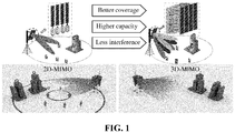
- an antenna architecture is as follows: multiple array elements are adopted in a vertical dimension, that is, N antennae are adopted, so that a higher antenna gain is obtained; and each antenna array element in the vertical dimension adopts a fixed weight to ensure that a required beam pattern is obtained in the vertical dimension. Therefore, under such a condition, it is impossible to use a precoding solution in the vertical dimension in the MIMO technology.
- weighting factors of different antenna array elements in the vertical dimension may be controlled to form different beams.
- the beams in the vertical dimension may be effectively distinguished, thereby providing multiple-user multiplexing in the vertical dimension and increasing a system capacity, as shown in FIG. 1 .
- a conventional LTE system supports a design of maximally 8 antennae, and 3D MIMO extends an antenna channel number, and supports a 3D antenna form with a channel number of 16, 32, 64, 128 and the like.
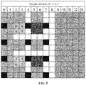
- FIG. 2 is a related CSI-RS pattern in an 8-port CSI-RS indication
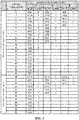
- FIG. 3 is a related configuration parameter indication table.
- 3GPP 3rd Generation Partnership Project
- an overhead of a CSI-RS configuration parameter is an RE in a PRB of a port.
- FDD Frequency Division Duplexing
- DwPTS Time Division Duplexing
- Table 1 shows a configuration of a special slot. From Table 1, it can be seen that #1, 2, 3, 4, 6, 7 and 8 are configured for the special slot (a DwPTS includes 9 ⁇ 12 OFDM symbols), so that a CSI-RS may be transmitted in the DwPTS. While in another special slot configuration, the DwPTS includes a small number of OFDM symbols, so that supporting transmission of the CSI-RS is not suggested.
- a 16-port design may adopt a combination of 2 8-port designs, and a 12-port design may adopt a combined form of 3 4-port designs or an 8+4 design.
- UE when CSI-RS configuration parameter information is acquired, UE acquires a sending period of a CSI-RS and an offset of a subframe where it is located through subframeConfig-r10 in an Information Element (IE)-CSI-RS-Config in TS36.331, and then acquires a specific CSI-RS pattern through resourceConfigu-r10. Or the UE acquires the sending period of the CSI-RS and the offset of the subframe where it is located through subframeconfig-r11 in an IE-CSI-RS-ConfigNZP, and then acquires the specific CSI-RS pattern through resourceConfig-r11.
- IE Information Element
- the UE acquires the sending period of the CSI-RS and the offset of the subframe where it is located through subframeconfig-r11 in an IE-CSI-RS-ConfigZP, and then acquires the specific CSI-RS pattern through resourceConfigList-r11. Or the UE acquires the sending period of the CSI-RS and the offset of the subframe where it is located through subframeConfig-r12 in CSI-IM-Config, and then acquires the specific CSI-RS pattern through resourceConfig-r12.
- the solution not only involves standard modification to a Radio Access Network 1 (RAN1), but also requires modification to a standard protocol of a RAN2, so that the standard is greatly modified, that is, the related RRC signaling is required to be modified more. Therefore, a signaling overhead is increased.
- RAN1 Radio Access Network 1
- RAN2 Radio Access Network 2
- a base station when a CSI-RS is transmitted through a DwPTS, a base station generates RRC signaling that indicates a CSI-RS resource configuration, and sends the RRC signaling to UE, where, when the RRC signaling that indicates the CSI-RS resource configuration is generated, a first field in the RRC signaling is configured to indicate a special slot, and a second field in the RRC signaling is configured to indicate a CSI-RS pattern in the special slot; and the UE receives the RRC signaling, acquires the first field in the RRC signaling, and when the first field is determined to indicate the special slot and the UE meets a preset condition, the CSI-RS pattern in the special slot is determined according to the CSI-RS pattern indicated by the second field in the RRC signaling, the first field indicating a CSI-RS subframe configuration and the second field indicating the CSI-RS configuration.
- the embodiments provide a CSI-RS indication method, which is applied to a base station. As shown in FIG. 6 , the method includes the following steps.
- CSI-RS configuration parameters are allocated to UE.
- RRC signaling that indicates a CSI-RS resource configuration is generated according to information about the CSI-RS configuration parameters allocated to the UE, and the RRC signaling is sent to the UE.
- a first field in the RRC signaling is configured to indicate a special slot
- a second field in the RRC signaling is configured to indicate a CSI-RS pattern in the special slot
- the configured special slot is configured to notify the UE meeting a preset condition to acquire the CSI-RS pattern indicated by the second field.
- the first field indicates a CSI-RS subframe configuration
- the second field indicates a CSI-RS configuration
- the first field and the second field may adopt related fields in the 3GPP R12 standard.
- values of the first field and the second field may also be different, specifically as follows:
- the preset condition refers to that the UE is new UE, rather than conventional UE (legacy UE).
- the conventional UE refers to UE meeting the 3GPP R12 (namely meeting the 3GPP R12 standard) and versions before the 3GPP R12; and correspondingly, the new UE refers to UE meeting the 3GPP R13 (meeting the 3GPP R13 standard).
- the operation that the second field in the RRC signaling is configured to indicate the CSI-RS pattern in the special slot specifically includes that:
- the 20 1-port or 2-port CSI-RS configuration parameters include the following parameters: k' is 9, l' is 2 and ns mod 2 is 0; k is 8, l' is 2 and ns mod 2 is 0; k is 3, l' is 2 and n s mod 2 is 0; k' is 2, l' is 2 and n s mod 2 is 0; k is 11, l' is 5 and n s mod 2 is 0; k is 10, l' is 5 and n s mod 2 is 0; k is 7, l' is 5 and n s mod 2 is 0; k' is 6, l' is 5 and n s mod 2 is 0; k is 5, l' is 5 and n s mod 2 is 0; k is 4, l' is 5 and n s mod 2 is 0; k' is 1, l' is 5 and n s mod 2 is 0; k' is 0, l' is 5 and n
- the 10 4-port CSI-RS configuration parameters include the following parameters: k' is 9, l' is 2 and ns mod 2 is 0; k is 8, l' is 2 and ns mod 2 is 0; k' is 11, l' is 5 and n s mod 2 is 0; k is 10, l' is 5 and n s mod 2 is 0; k' is 7, l' is 5 and n s mod 2 is 0; k is 6, l' is 5 and n s mod 2 is 0; k' is 5, l' is 5 and n s mod 2 is 0; k' is 8, l' is 5 and n s mod 2 is 0; k' is 9, l' is 2 and n s mod 2 is 1; and k' is 8, l' is 2 and n s mod 2 is 1.
- the 5 8-port CSI-RS configuration parameters include the following parameters: k' is 9, l' is 2 and ns mod 2 is 0; k is 11, l' is 5 and ns mod 2 is 0; k' is 7, l' is 5 and n s mod 2 is 0; k' is 9, l' is 5 and n s mod 2 is 0; and k' is 9, l' is 2 and n s mod 2 is 1.
- a location of an RE occupied by the CSI-RS in a PRB pair is represented by (k, l'), k represents a row where the RE is located, l' represents a column where the RE is located, ns represents a slot number, each subframe includes two slots, and mod represents remainder calculation.
- a base station side selects the CSI-RS pattern in FIG. 4 or FIG. 5 for CSI-RS transmission according to a configuration of the special slot, k' being numbered to be 0 ⁇ 11 from bottom to top respectively and numbers of l' being 0 ⁇ 6.
- Table 2 CSI reference signal configuration Number of CSI reference signals configured 1 or 2 4 8 ( k' , l' ) n s mod 2 ( k' , l' ) n s mod 2 ( k' , l ') n s mod 2 CSI-RS in DwPTS 0 (9,2) 0 (9,2) 0 (9,2) 0 1 (8,2) 0 (8,2) 0 (11,5) 0 2 (3,2) 0 (11,5) 0 (7,5) 0 3 (2,2) 0 (10,5) 0 4 (11,5) 0 (7,5) 0 5 (10,5) 0 (6,5) 0 6 (7,5) 0 7 (6,5) 0 8 (5,5) 0 9 (4,5) 0 10 (1,5) 0 11 (0,5) 0 12 (9,5) 0 (9,5) 0 (9,5) 0 9,5) 0 13 (8,5) 0 (8,5) 0 (8,5) 0
- the second field is resourceConfig-r12, resourceConfig-r11 or resourceConfig-rlO
- the second field has a value up to 20; and when the second field is resourceConfigList-r11, resourceConfigList-r11 has a value up to 10, and may indicate multiple 4-port and 8-port CSI-RS configuration parameters.
- the CSI-RS configuration corresponding to 1 or 2 antenna ports is not included.
- a certain offset (3 or 4 symbols) is added to the related CSI-RS pattern (for example, the CSI-RS patterns shown in FIG. 2 and FIG. 3 ) to acquire the CSI-RS pattern in the special slot.
- the operation that the second field in the RRC signaling is configured to indicate the CSI-RS pattern in the special slot specifically includes that:
- l' DwPTS represents l' in the CSI-RS pattern in the special slot
- (n s mod2) DwPTS represents ns mod 2 in the CSI-RS pattern in the special slot
- l' represents l' in the default CSI-RS pattern
- ns mod 2 represents ns mod 2 in the default CSI-RS pattern.
- the default CSI-RS pattern refers to a CSI-RS pattern (as shown in FIG. 2 and FIG. 3 ) in the related standard (the 3GPP R12 standard).
- an OFDM symbol offset manner may also be adopted for representation.
- the operation that the second field in the RRC signaling is configured to indicate the CSI-RS pattern in the special slot specifically includes that:
- the embodiments further provide a CSI-RS indication method, which is applied to UE. As shown in FIG. 7 , the method includes the following steps.
- a CSI-RS pattern in the special slot is determined according to a CSI-RS pattern indicated by a second field in the RRC signaling.
- the first field indicates a CSI-RS subframe configuration
- the second field indicates a CSI-RS configuration
- values of the first field and the second field may also be different, specifically as follows:
- the preset condition refers to that the UE is new UE, rather than conventional UE (legacy UE).
- the conventional UE refers to UE meeting the 3GPP R12 (namely meeting the 3GPP R12 standard) and versions before the 3GPP R12; and correspondingly, the new UE refers to UE meeting the 3GPP R13 (meeting the 3GPP R13 standard).
- the operation that the CSI-RS pattern in the special slot is determined according to the CSI-RS pattern indicated by the second field in the RRC signaling specifically includes that:
- the 20 1-port or 2-port CSI-RS configuration parameters include the following parameters: k' is 9, l' is 2 and ns mod 2 is 0; k is 8, l' is 2 and ns mod 2 is 0; k is 3, l' is 2 and n s mod 2 is 0; k' is 2, l' is 2 and n s mod 2 is 0; k is 11, l' is 5 and n s mod 2 is 0; k is 10, l' is 5 and n s mod 2 is 0; k is 7, l' is 5 and n s mod 2 is 0; k' is 6, l' is 5 and n s mod 2 is 0; k is 5, l' is 5 and n s mod 2 is 0; k is 4, l' is 5 and n s mod 2 is 0; k' is 1, l' is 5 and n s mod 2 is 0; k' is 0, l' is 5 and n
- the 10 4-port CSI-RS configuration parameters include the following parameters: k' is 9, l' is 2 and ns mod 2 is 0; k is 8, l' is 2 and ns mod 2 is 0; k' is 11, l' is 5 and n s mod 2 is 0; k is 10, l' is 5 and n s mod 2 is 0; k' is 7, l' is 5 and n s mod 2 is 0; k is 6, l' is 5 and n s mod 2 is 0; k' is 5, l' is 5 and n s mod 2 is 0; k' is 8, l' is 5 and n s mod 2 is 0; k' is 9, l' is 2 and n s mod 2 is 1; and k' is 8, l' is 2 and n s mod 2 is 1.
- the 5 8-port CSI-RS configuration parameters include the following parameters: k' is 9, l' is 2 and ns mod 2 is 0; k is 11, l' is 5 and ns mod 2 is 0; k' is 7, l' is 5 and n s mod 2 is 0; k' is 9, l' is 5 and n s mod 2 is 0; and k' is 9, l' is 2 and n s mod 2 is 1.
- a location of an RE occupied by the CSI-RS in a PRB pair is represented by (k, l'), k represents a row where the RE is located, l' represents a column where the RE is located, ns represents a slot number, each subframe includes two slots, and mod represents remainder calculation.
- k' is numbered to be 0 ⁇ 11 from bottom to top respectively and numbers of l' are 0 ⁇ 6.
- the CSI-RS configuration parameter indication table shown in Table 2 is formed.
- the second field is resourceConfig-r12, resourceConfig-r11 or resourceConfig-rlO
- the second field has a value up to 20
- resourceConfigList-r11 resourceConfigList-r11 has a value up to 10
- the CSI-RS configuration corresponding to 1 or 2 antenna ports is not included.
- a certain offset (3 or 4 symbols) is added to the related CSI-RS pattern (for example, the CSI-RS patterns shown in FIG. 2 and FIG. 3 ) to acquire the CSI-RS pattern in the special slot.
- the operation that the CSI-RS pattern in the special slot is determined according to the CSI-RS pattern indicated by the second field in the RRC signaling specifically includes that:
- l' DwPTS represents l' in the CSI-RS pattern in the special slot
- (n s mod2) DwPTS represents ns mod 2 in the CSI-RS pattern in the special slot
- l' represents l' in the default CSI-RS pattern
- ns mod 2 represents ns mod 2 in the default CSI-RS pattern.
- the default CSI-RS pattern refers to a CSI-RS pattern (as shown in FIG. 2 and FIG. 3 ) in the related standard (the 3GPP R12 standard).
- an OFDM symbol offset manner may also be adopted for representation.
- the embodiments further provide a CSI-RS indication method. As shown in FIG. 8 , the method includes the following steps.
- a base station when a CSI-RS is transmitted through a DwPTS, a base station allocates CSI-RS configuration parameters to UE, generates RRC signaling that indicates a CSI-RS resource configuration according to information about the CSI-RS configuration parameters allocated to the UE, and sends the RRC signaling to the UE.
- a subframeconfig-r11 field in the RRC signaling is configured to indicate a special slot
- a resourceConfig-r11 field in the RRC signaling is configured to indicate a CSI-RS pattern in the special slot.
- the UE receives the RRC signaling, acquires the subframeconfig-r11 field in the RRC signaling, and when a configuration of the subframeconfig-r11 field is determined to be the special slot and the UE meets a preset condition, determines the CSI-RS pattern in the special slot according to the CSI-RS pattern indicated by the resourceConfig-r11 field in the RRC signaling.
- the first field indicates a CSI-RS subframe configuration
- the second field indicates a CSI-RS configuration
- the base station when the CSI-RS is transmitted through the DwPTS, the base station generates the RRC signaling that indicates the CSI-RS resource configuration, and sends the RRC signaling to the UE, where, when the RRC signaling that indicates the CSI-RS resource configuration is generated, the subframeconfig-r11 field in the RRC signaling is configured to indicate the special slot, and the resourceConfig-r11 field in the RRC signaling is configured to indicate the CSI-RS pattern in the special slot; and the UE receives the RRC signaling, acquires the first field in the RRC signaling, and when the first field is determined to indicate the special slot and the UE meets the preset condition, determines the CSI-RS pattern in the special slot according to the CSI-RS pattern indicated by the second field in the RRC signaling, the first field indicating the CSI-RS subframe configuration and the second field indicating the CSI-RS configuration.
- the configuration information may be described in three forms of a new table, a formula and an offset, the 36331 standard is not modified, and the new UE utilizes the related RRC signaling for re-reading. Therefore, the related RRC signaling is not required to be modified, and a signaling overhead is greatly reduced.
- the embodiments provide a base station.
- the base station includes: a generation unit 91 and a sending unit 92, where the generation unit 91 is configured to generate RRC signaling that indicates a CSI-RS resource configuration according to information about CSI-RS configuration parameters allocated to UE; and the sending unit 92 is configured to send the RRC signaling to the UE, where, when the RRC signaling that indicates the CSI-RS resource configuration is generated, the generation unit 91 configures a first field in the RRC signaling to indicate a special slot and configures a second field in the RRC signaling to indicate a CSI-RS pattern in the special slot; and the configured special slot is configured to notify the UE meeting a preset condition to acquire the CSI-RS pattern indicated by the second field.
- the base station further includes an allocation unit, configured to, when a CSI-RS is transmitted through a DwPTS, allocate the CSI-RS configuration parameters to the UE; and correspondingly, the generation unit 91 is configured to generate the RRC signaling that indicates the CSI-RS resource configuration according to the information about the CSI-RS configuration parameters allocated to the UE.
- the first field and the second field may adopt related fields in the 3GPP R12 standard.
- values of the first field and the second field may also be different, specifically as follows:
- the preset condition refers to that the UE is new UE, rather than conventional UE (legacy UE).
- the conventional UE refers to UE meeting the 3GPP R12 (namely meeting the 3GPP R12 standard) and versions before the 3GPP R12; and correspondingly, the new UE refers to UE meeting the 3GPP R13 (meeting the 3GPP R13 standard).
- the generation unit 91 is specifically configured to configure the second field to be a serial number corresponding to the CSI-RS pattern in the special slot in the CSI-RS configuration parameter table; and the CSI-RS configuration parameter indication table includes 20 1-port CSI-RS configuration parameters, 20 2-port CSI-RS configuration parameters, 10 4-port CSI-RS configuration parameters and 5 8-port CSI-RS configuration parameters, where the 20 1-port CSI-RS configuration parameters are the same as the 20 2-port CSI-RS configuration parameters.
- the 20 1-port or 2-port CSI-RS configuration parameters include the following parameters: k' is 9, l' is 2 and ns mod 2 is 0; k is 8, l' is 2 and ns mod 2 is 0; k is 3, l' is 2 and n s mod 2 is 0; k' is 2, l' is 2 and n s mod 2 is 0; k is 11, l' is 5 and n s mod 2 is 0; k is 10, l' is 5 and n s mod 2 is 0; k is 7, l' is 5 and n s mod 2 is 0; k' is 6, l' is 5 and n s mod 2 is 0; k is 5, l' is 5 and n s mod 2 is 0; k is 4, l' is 5 and n s mod 2 is 0; k' is 1, l' is 5 and n s mod 2 is 0; k' is 0, l' is 5 and n
- the 10 4-port CSI-RS configuration parameters include the following parameters: k' is 9, l' is 2 and ns mod 2 is 0; k is 8, l' is 2 and ns mod 2 is 0; k' is 11, l' is 5 and n s mod 2 is 0; k is 10, l' is 5 and n s mod 2 is 0; k' is 7, l' is 5 and n s mod 2 is 0; k is 6, l' is 5 and n s mod 2 is 0; k' is 5, l' is 5 and n s mod 2 is 0; k' is 8, l' is 5 and n s mod 2 is 0; k' is 9, l' is 2 and n s mod 2 is 1; and k' is 8, l' is 2 and n s mod 2 is 1.
- the 5 8-port CSI-RS configuration parameters include the following parameters: k' is 9, l' is 2 and ns mod 2 is 0; k is 11, l' is 5 and ns mod 2 is 0; k' is 7, l' is 5 and n s mod 2 is 0; k' is 9, l' is 5 and n s mod 2 is 0; and k' is 9, l' is 2 and n s mod 2 is 1.
- a location of an RE occupied by the CSI-RS in a PRBpair is represented by (k, l'), k represents a row where the RE is located, l' represents a column where the RE is located, ns represents a slot number, each subframe includes two slots, and mod represents remainder calculation.
- k' is numbered to be 0 ⁇ 11 from bottom to top respectively and numbers of l' are 0 ⁇ 6.
- the second field is resourceConfig-r12, resourceConfig-r11 or resourceConfig-rlO
- the second field has a value up to 20; and when the second field is resourceConfigList-r11, resourceConfigList-r11 has a value up to 10, and may indicate multiple 4-port and 8-port CSI-RS configuration parameters.
- the CSI-RS configuration corresponding to 1 or 2 antenna ports is not included.
- a certain offset (3 or 4 symbols) is added to the related CSI-RS pattern (for example, the CSI-RS patterns shown in FIG. 2 and FIG. 3 ) to acquire the CSI-RS pattern in the special slot.
- the generation unit 91 is specifically configured to configure the second field to indicate a corresponding relationship between a default CSI-RS pattern and a CSI-RS pattern in the special slot, the corresponding relationship including a corresponding relationship between l' and n s mod 2, where, when l' in the default CSI-RS pattern is more than 3, l' in the CSI-RS pattern in the special slot is a difference between l' in the default CSI-RS pattern and 3; when l' in the default CSI-RS pattern is less than or equal to 3, l' in the CSI-RS pattern in the special slot is a remainder obtained through dividing, by 7, a sum of l' in the default CSI-RS pattern and 10, i.e.
- l' DwPTS represents l' in the CSI-RS pattern in the special slot
- (n s mod2) DwPTS represents ns mod 2 in the CSI-RS pattern in the special slot
- l' represents l' in the default CSI-RS pattern
- ns mod 2 represents ns mod 2 in the default CSI-RS pattern.
- the default CSI-RS pattern refers to a CSI-RS pattern (as shown in FIG. 2 and FIG. 3 ) in the related standard (the 3GPP R12 standard).
- an OFDM symbol offset manner may also be adopted for representation.
- the generation unit 91 is specifically configured to generate a CSI-RS configuration in the special slot according to an offset of the CSI-RS pattern in the special slot from the default CSI-RS pattern, where, when l' in the default CSI-RS pattern is more than 3, the CSI-RS pattern in the special slot is obtained by shifting the default CSI-RS pattern leftwards by 3 OFDM symbols; when l' in the default CSI-RS pattern is less than or equal to 3, the CSI-RS pattern in the special slot is obtained by shifting l' in the default CSI-RS pattern leftwards by 4 OFDM symbols; and the location of the RE occupied by the CSI-RS in the PRB pair is represented by (k', l'), k' represents the line where the RE is located, each row is a subcarrier, l' represents the column where the RE is located, and each column is an OFDM symbol.
- the allocation unit and the generation unit 91 may be implemented by a Central Processing Unit (CPU), Micro Control Unit (MCU), Digital Signal Processor (DSP) or Field Programmable Gate Array (FPGA) in the base station; and the sending unit 92 may be implemented in a transmitter in the base station.
- CPU Central Processing Unit
- MCU Micro Control Unit
- DSP Digital Signal Processor
- FPGA Field Programmable Gate Array
- the embodiments further provide UE.
- the UE includes: a receiving unit 101, a first acquisition unit 102 and a second acquisition unit 103, where the receiving unit 101 is configured to, when a CSI-RS is transmitted through a DwPTS, receive RRC signaling that indicates a CSI-RS resource configuration; the first acquisition unit 102 is configured to acquire a first field in the RRC signaling; and the second acquisition unit 103 is configured to, when the first field is determined to indicate a special slot and the UE meets a preset condition, determine a CSI-RS pattern in the special slot according to a CSI-RS pattern indicated by a second field in the RRC signaling.
- the first field indicates a CSI-RS subframe configuration
- the second field indicates a CSI-RS configuration
- values of the first field and the second field may also be different, specifically as follows:
- the preset condition refers to that the UE is new UE, rather than conventional UE (legacy UE).
- the conventional UE refers to UE meeting the 3GPP R12 (namely meeting the 3GPP R12 standard) and versions before the 3GPP R12; and correspondingly, the new UE refers to UE meeting the 3GPP R13 (meeting the 3GPP R13 standard).
- the second acquisition unit 103 is specifically configured to acquire, in a CSI-RS configuration parameter indication table, a serial number corresponding to the CSI-RS pattern in the special slot indicated by the second field, and determine the CSI-RS pattern in the special slot according to an acquired number of CSI-RS ports and the serial number, the CSI-RS configuration parameter indication table including 20 1-port CSI-RS configuration parameters, 20 2-port CSI-RS configuration parameters, 10 4-port CSI-RS configuration parameters and 5 8-port CSI-RS configuration parameters, where the 20 1-port CSI-RS configuration parameters are the same as the 20 2-port CSI-RS configuration parameters.
- the 20 1-port or 2-port CSI-RS configuration parameters include the following parameters: k' is 9, l' is 2 and ns mod 2 is 0; k is 8, l' is 2 and ns mod 2 is 0; k is 3, l' is 2 and n s mod 2 is 0; k' is 2, l' is 2 and n s mod 2 is 0; k is 11, l' is 5 and n s mod 2 is 0; k is 10, l' is 5 and n s mod 2 is 0; k is 7, l' is 5 and n s mod 2 is 0; k' is 6, l' is 5 and n s mod 2 is 0; k is 5, l' is 5 and n s mod 2 is 0; k is 4, l' is 5 and n s mod 2 is 0; k' is 1, l' is 5 and n s mod 2 is 0; k' is 0, l' is 5 and n
- the 10 4-port CSI-RS configuration parameters include the following parameters: k' is 9, l' is 2 and ns mod 2 is 0; k is 8, l' is 2 and ns mod 2 is 0; k' is 11, l' is 5 and n s mod 2 is 0; k is 10, l' is 5 and n s mod 2 is 0; k' is 7, l' is 5 and n s mod 2 is 0; k is 6, l' is 5 and n s mod 2 is 0; k' is 5, l' is 5 and n s mod 2 is 0; k' is 8, l' is 5 and n s mod 2 is 0; k' is 9, l' is 2 and n s mod 2 is 1; and k' is 8, l' is 2 and n s mod 2 is 1.
- the 5 8-port CSI-RS configuration parameters include the following parameters: k' is 9, l' is 2 and ns mod 2 is 0; k is 11, l' is 5 and ns mod 2 is 0; k' is 7, l' is 5 and n s mod 2 is 0; k' is 9, l' is 5 and n s mod 2 is 0; and k' is 9, l' is 2 and n s mod 2 is 1.
- a location of an RE occupied by the CSI-RS in a PRBpair is represented by (k, l'), k represents a row where the RE is located, l' represents a column where the RE is located, ns represents a slot number, each subframe includes two slots, and mod represents remainder calculation.
- k' is numbered to be 0 ⁇ 11 from bottom to top respectively and numbers of l' are 0 ⁇ 6.
- the second field is resourceConfig-r12, resourceConfig-r11 or resourceConfig-rlO
- the second field has a value up to 20; and when the second field is resourceConfigList-r11, resourceConfigList-r11 has a value up to 10, and may indicate multiple 4-port and 8-port CSI-RS configuration parameters.
- the CSI-RS configuration corresponding to 1 or 2 antenna ports is not included.
- a certain offset (3 or 4 symbols) is added to the related CSI-RS pattern (for example, the CSI-RS patterns shown in FIG. 2 and FIG. 3 ) to acquire the CSI-RS pattern in the special slot.
- the second acquisition unit 103 is specifically configured to:
- l' Dw PTS represents l' in the CSI-RS pattern in the special slot
- (n s mod2) DwPTS represents ns mod 2 in the CSI-RS pattern in the special slot
- l' represents l' in the default CSI-RS pattern
- ns mod 2 represents ns mod 2 in the default CSI-RS pattern.
- the default CSI-RS pattern refers to a CSI-RS pattern (as shown in FIG. 2 and FIG. 3 ) in the related standard (the 3GPP R12 standard).
- an OFDM symbol offset manner may also be adopted for representation.
- the second acquisition unit 103 is specifically configured to acquire a CSI-RS configuration in the special slot indicated by the second field, where the CSI-RS configuration in the special slot is generated according to an offset of the CSI-RS pattern in the special slot from the default CSI-RS pattern, and determine the CSI-RS pattern in the special slot is determined according to the configuration and the default CSI-RS pattern, where, when l' in the default CSI-RS pattern is more than 3, the CSI-RS pattern in the special slot is obtained by shifting the default CSI-RS pattern leftwards by 3 OFDM symbols; when l' in the default CSI-RS pattern is less than or equal to 3, the CSI-RS pattern in the special slot is obtained by shifting l' in the default CSI-RS pattern leftwards by 4 OFDM symbols; and the location of the RE occupied by the CSI-RS in the PRB pair is represented by (k, l'), k represents the row where the RE is located, each row is a subcarrier, l' represents the column where
- the receiving unit 101 may be implemented by a receiver in the UE; and the first acquisition unit 102 and the second acquisition unit 103 may be implemented by a CPU, MCU, DSP or FPGA in the UE.
- the examples further provide a CSI-RS indication system.
- the system includes: a base station 111 and UE 112, where the base station 111 is configured to, when a CSI-RS is transmitted through a DwPTS, generate RRC signaling that indicates a CSI-RS resource configuration, and send the RRC signaling to the UE 112, where, when the RRC signaling that indicates the CSI-RS resource configuration is generated, a first field in the RRC signaling is configured to indicate a special slot, and a second field in the RRC signaling is configured to indicate a CSI-RS pattern in the special slot; and the UE 112 is configured to receive the RRC signaling, acquire the first field in the RRC signaling, and when the first field is determined to indicate the special slot and the UE meets a preset condition, determine the CSI-RS pattern in the special slot according to the CSI-RS pattern indicated by the second field in the RRC signaling.
- the first field indicates a CSI-RS subframe configuration
- the second field indicates a CSI-RS configuration
- the base station when the CSI-RS is transmitted through the DwPTS, the base station generates the RRC signaling that indicates the CSI-RS resource configuration, and sends the RRC signaling to the UE, where, when the RRC signaling that indicates the CSI-RS resource configuration is generated, the first field in the RRC signaling is configured to indicate the special slot, and the second field in the RRC signaling is configured to indicate the CSI-RS pattern in the special slot; and the UE receives the RRC signaling, acquires the first field in the RRC signaling, and when the first field is determined to indicate the special slot and the UE meets the preset condition, determines the CSI-RS pattern in the special slot according to the CSI-RS pattern indicated by the second field in the RRC signaling, the first field indicating the CSI-RS subframe configuration and the second field indicating the CSI-RS configuration.
- the configuration information may be described in three forms of a new table, a formula and an offset, the 36331 standard is not modified, and the new UE utilizes the related RRC signaling for re-reading. Therefore, the related RRC signaling is not required to be modified, and a signaling overhead is greatly reduced.
- the example of the disclosure may be provided as a method, a system or a computer program product. Therefore, the disclosure may adopt a form of hardware example, software example and combined software and hardware example. Moreover, the disclosure may adopt a form of computer program product implemented on one or more computer-available storage media (including, but not limited to, a disk memory and an optical memory) including computer-available program codes.
- a computer-available storage media including, but not limited to, a disk memory and an optical memory
- each flow and/or block in the flowcharts and/or the block diagrams and combinations of the flows and/or blocks in the flowcharts and/or the block diagrams may be implemented by computer program instructions.
- These computer program instructions may be provided for a universal computer, a dedicated computer, an embedded processor or a processor of other programmable data processing equipment to generate a machine, so that a device for realizing a function specified in one flow or more flows in the flowcharts and/or one block or more blocks in the block diagrams is generated by the instructions executed through the computer or the processor of the other programmable data processing equipment.
- These computer program instructions may also be stored in a computer-readable memory capable of guiding the computer or the other programmable data processing equipment to work in a specific manner, so that a product including an instruction device may be generated by the instructions stored in the computer-readable memory, the instruction device realizing the function specified in one flow or many flows in the flowcharts and/or one block or many blocks in the block diagrams.
- These computer program instructions may further be loaded onto the computer or the other programmable data processing equipment, so that a series of operating steps are executed on the computer or the other programmable data processing equipment to generate processing implemented by the computer, and steps for realizing the function specified in one flow or many flows in the flowcharts and/or one block or many blocks in the block diagrams are provided by the instructions executed on the computer or the other programmable data processing equipment.
Landscapes
- Engineering & Computer Science (AREA)
- Signal Processing (AREA)
- Computer Networks & Wireless Communication (AREA)
- Mobile Radio Communication Systems (AREA)
Claims (6)
- Verfahren zur Anzeige eines Kanalzustandsinformation-Referenzsignals (CSI-RS), das auf eine Basisstation angewendet wird, wobei das Verfahren umfasst:wenn ein CSI-RS durch einen Abwärtsverbindungs-Pilotzeitslot (DwPTS) übertragen wird, Erzeugen einer Funkressourcensteuerungs-, (RRC)-Signalisierung, die eine CSI-RS-Ressourcenkonfiguration anzeigt; und Senden der RRC-Signalisierung an ein Benutzergerät (UE),wobei Erzeugen der RRC-Signalisierung, die die CSI-RS-Ressourcenkonfiguration anzeigt, umfasst: Konfigurieren eines ersten Felds in der RRC-Signalisierung, um einen besonderen Slot anzuzeigen, und Konfigurieren eines zweiten Felds in der RRC-Signalisierung, um eine CSI-RS-Struktur in dem besonderen Slot anzuzeigen; wobei der besondere Slot konfiguriert ist, um das UE, das einen 3GPP R13 Standard erfüllt, zu benachrichtigen, um die CSI-RS-Struktur, die von dem zweiten Feld angezeigt wird, zu beziehen; undwobei das erste Feld eine CSI-RS-Teilrahmenkonfiguration anzeigt und das zweite Feld eine CSI-RS-Konfiguration anzeigt; undwobei Konfigurieren des zweiten Felds in der RRC-Signalisierung zum Anzeigen der CSI-RS-Struktur in dem besonderen Slot umfasst:Konfigurieren des zweiten Felds zum Anzeigen einer entsprechenden Beziehung zwischen einer 3GPP R12 CSI-RS-Struktur und der CSI-RS-Struktur in dem besonderen Slot, wobei die entsprechende Beziehung eine entsprechende Beziehung zwischen l' und ns mod 2 umfasst; wobei,wenn I' in der 3GPP R12 CSI-RS-Struktur größer als 3 ist, I' in der CSI-RS-Struktur in dem besonderen Slot eine Differenz zwischen I' in der 3GPP R12 CSI-RS-Struktur und 3 ist;wenn I' in der 3GPP R12 CSI-RS-Struktur kleiner oder gleich 3 ist, I' in der CSI-RS-Struktur in dem besonderen Slot ein Rest ist, der durch Dividieren einer Summe von l' in der 3GPP R12 CSI-RS-Struktur und 10 durch 7 erhalten wird;wenn I' in der 3GPP R12 CSI-RS-Struktur größer als 3 ist und ns mod 2 in der 3GPP R12 CSI-RS-Struktur gleich 1 ist, ns mod 2 in der CSI-RS-Struktur in dem besonderen Slot 1 ist;außer wenn I' in der 3GPP R12 CSI-RS-Struktur größer als 3 ist und ns mod 2 in der 3GPP R12 CSI-RS-Struktur gleich 1 ist, ns mod 2 in der CSI-RS-Struktur in dem besonderen Slot 0 ist; unddie Stelle eines Ressourcenelements (RE), die von dem CSI-RS in einem physischen Ressourcenblock-, (PRB)-Paar besetzt ist, durch (k', l') dargestellt ist, wobei k' eine Reihe repräsentiert, wo das RE liegt, I' eine Spalte repräsentiert, wo das RE liegt und ns eine Slot-Zahl repräsentiert.
- Verfahren nach Anspruch 1, wobei das erste Feld subframeConfig-r12 ist und das zweite Feld resourceConfig-r12 ist;
oder das erste Feld subframeConfig-r11 ist und das zweite Feld ressourceConfigList-r11 oder ressourceConfigList-r11 ist;
oder das erste Feld subframeConfig-r10 ist und das zweite Feld resourceConfig-r10 ist. - Verfahren zur Anzeige eines Kanalzustandsinformation-Referenzsignals (CSI-RS), das auf ein Benutzergerät (UE) angewendet wird, wobei das Verfahren umfasst:wenn ein CSI-RS durch einen Abwärtsverbindungs-Pilotzeitslot (DwPTS) übertragen wird, Empfangen von Funkressourcensteuerungs-, (RRC)-Signalisierung, die eine CSI-RS-Ressourcenkonfiguration anzeigt;Beziehen eines ersten Felds in der RRC-Signalisierung; undwenn das erste Feld bestimmt ist, einen besonderen Slot anzuzeigen, und die UE einen 3GPP R13 Standard erfüllt, Bestimmen einer CSI-RS-Struktur in dem besonderen Slot gemäß einer CSI-RS-Struktur, die von einem zweiten Feld in der RRC-Signalisierung angezeigt wird,wobei das erste Feld eine CSI-RS-Teilrahmenkonfiguration anzeigt und das zweite Feld eine CSI-RS-Konfiguration anzeigt; undwobei Bestimmen der CSI-RS-Struktur in dem besonderen Slot gemäß der CSI-RS-Struktur, die von dem zweiten Feld in der RRC-Signalisierung angezeigt wird, umfasst:Beziehen einer entsprechenden Beziehung, die von dem zweiten Feld angezeigt wird, zwischen einer 3GPP R12 CSI-RS-Struktur und der CSI-RS-Struktur in dem besonderen Slot, wobei die entsprechende Beziehung eine entsprechende Beziehung zwischen l' und ns mod 2 umfasst; undBestimmen der CSI-RS-Struktur in dem besonderen Slot gemäß der entsprechenden Beziehung und der 3GPP R12 CSI-RS-Struktur, wobeiBestimmen der CSI-RS-Struktur in dem besonderen Slot gemäß der entsprechenden Beziehung und der 3GPP R12 CSI-RS-Struktur umfasst:wenn l' in der 3GPP R12 CSI-RS-Struktur größer als 3 ist, Berechnen einer Differenz zwischen I' in der 3GPP R12 CSI-RS-Struktur und 3, um I' in der CSI-RS-Struktur in dem besonderen Slot zu erhalten;wenn I' in der 3GPP R12 CSI-RS-Struktur kleiner oder gleich 3 ist, Bestimmen von I' in der CSI-RS-Struktur in dem besonderen Slot, ein Rest zu sein, der durch Dividieren einer Summe von I' in der 3GPP R12 CSI-RS-Struktur und 10 durch 7 erhalten wird;wenn I' in der 3GPP R12 CSI-RS-Struktur größer als 3 ist und ns mod 2 in der 3GPP R12 CSI-RS-Struktur gleich 1 ist, Bestimmen von ns mod 2 in der CSI-RS-Struktur in dem besonderen Slot, 1 zu sein; undaußer wenn I' in der 3GPP R12 CSI-RS-Struktur größer als 3 ist und ns mod 2 in der 3GPP R12 CSI-RS-Struktur gleich 1 ist, Bestimmen von ns mod 2 in der CSI-RS-Struktur in dem besonderen Slot, 0 zu sein,die Stelle eines Ressourcenelements (RE), die von dem CSI-RS in einem physischen Ressourcenblock-, (PRB)-Paar besetzt ist, durch (k', l') repräsentiert ist, wobei k' eine Reihe anzeigt, wo das RE liegt, I' eine Spalte anzeigt, wo das RE liegt und ns eine Slot-Zahl anzeigt.
- Verfahren nach Anspruch 3, wobei das erste Feld subframeConfig-r12 ist und das zweite Feld resourceConfig-r12 ist;
oder das erste Feld subframeConfig-r11 ist und das zweite Feld resourceConfig-r11 oder resourceConfigList-r11 ist;
oder das erste Feld subframeConfig-r10 ist und das zweite Feld resourceConfig-r10 ist. - Basisstation, umfassend eine Erzeugungseinheit und eine Sendeeinheit, wobei
die Erzeugungseinheit konfiguriert ist, um wenn ein Kanalzustandsinformationsreferenzsignal (CSI-RS) durch einen Abwärtsverbindungs-Pilotzeitslot (DwPTS) übertragen wird, eine Funkressourcensteuerungs-, (RRC)-Signalisierung zu erzeugen, die eine CSI-RS-Ressourcenkonfiguration anzeigt; und
die Sendeeinheit konfiguriert ist, um die RRC-Signalisierung an ein Benutzergerät (UE) zu senden, wobei
wenn die RRC-Signalisierung, die die CSI-RS-Ressourcenkonfiguration anzeigt, erzeugt wird, die Erzeugungseinheit ein erstes Feld in der RRC-Signalisierung konfiguriert, um einen besonderen Slot anzuzeigen, und ein zweites Feld in der RRC-Signalisierung konfiguriert, um eine CSI-RS-Struktur in dem besonderen Slot anzuzeigen; wobei der konfigurierte besondere Slot konfiguriert ist, um das UE, das einen 3GPP R13 Standard erfüllt, zu benachrichtigen, um die CSI-RS-Struktur zu beziehen, die von dem zweiten Feld angezeigt wird; und
das erste Feld eine CSI-RS-Teilrahmenkonfiguration anzeigt und das zweite Feld eine CSI-RS-Konfiguration anzeigt;
wobei die Erzeugungseinheit konfiguriert ist, das zweite Feld zu konfigurieren, um eine entsprechende Beziehung zwischen einer 3GPP R12 CSI-RS-Struktur und der CSI-RS-Struktur in dem besonderen Slot anzuzeigen, wobei die entsprechende Beziehung eine entsprechende Beziehung zwischen l' und ns mod 2 umfasst, wobei
wenn I' in der 3GPP R12 CSI-RS-Struktur größer als 3 ist, I' in der CSI-RS-Struktur in dem besonderen Slot eine Differenz zwischen I' in der 3GPP R12 CSI-RS-Struktur und 3 ist;
wenn I' in der 3GPP R12 CSI-RS-Struktur kleiner oder gleich 3 ist, I' in der CSI-RS-Struktur in dem besonderen Slot ein Rest ist, der durch Dividieren einer Summe von l' in der 3GPP R12 CSI-RS-Struktur und 10 durch 7 erhalten wird;
wenn l' in der 3GPP R12 CSI-RS-Struktur größer als 3 ist und ns mod 2 in der 3GPP R12 CSI-RS-Struktur gleich 1 ist, ns mod 2 in der CSI-RS-Struktur in dem besonderen Slot 1 ist;
außer wenn l' in der 3GPP R12 CSI-RS-Struktur größer als 3 ist und ns mod 2 in der 3GPP R12 CSI-RS-Struktur gleich 1 ist, ns mod 2 in der CSI-RS-Struktur in dem besonderen Slot 0 ist; und
eine Stelle eines Ressourcenelements (RE), die von dem CSI-RS in einem physischen Ressourcenblock-, (PRB)-Paar besetzt ist, durch (k', l') repräsentiert ist, wobei k' eine Reihe repräsentiert, wo das RE liegt, l' eine Spalte repräsentiert, wo das RE liegt und ns eine Slot-Zahl repräsentiert. - Benutzergerät (UE), umfassend: eine Empfangseinheit, eine erste Bezugseinheit und eine zweite Bezugseinheit, wobei
die Empfangseinheit konfiguriert ist, um wenn ein Kanalzustandsinformationsreferenzsignal (CSI-RS) durch einen Abwärtsverbindungs-Pilotzeitslot (DwPTS) übertragen wird, Funkressourcensteuerungs-, (RRC)-Signalisierung zu empfangen, die eine CSI-RS-Ressourcenkonfiguration anzeigt;
die erste Bezugseinheit konfiguriert ist, um ein erstes Feld in der RRC-Signalisierung zu beziehen; und
die zweite Bezugseinheit konfiguriert ist, um wenn das erste Feld bestimmt ist, einen besonderen Slot anzuzeigen, und das UE einen 3GPP R13 Standard erfüllt, eine CSI-RS-Struktur in dem besonderen Slot gemäß einer CSI-RS-Struktur zu bestimmen, die von einem zweiten Feld in der RRC-Signalisierung angezeigt wird,
das erste Feld eine CSI-RS-Teilrahmenkonfiguration anzeigt und das zweite Feld eine CSI-RS-Konfiguration anzeigt;
wobei die zweite Bezugseinheit konfiguriert ist zum:Beziehen einer entsprechenden Beziehung, die von dem zweiten Feld angezeigt wird, zwischen einer 3GPP R12 CSI-RS-Struktur und der CSI-RS-Struktur in dem besonderen Slot, wobei die entsprechende Beziehung eine entsprechende Beziehung zwischen l' und ns mod 2 umfasst und Bestimmen der CSI-Struktur in dem besonderen Slot gemäß der entsprechenden Beziehung und der 3GPP R12 CSI-RS-Struktur, wobeiBestimmen der CSI-RS-Struktur in dem besonderen Slot gemäß der entsprechenden Beziehung und der 3GPP R12 CSI-RS-Struktur umfasst:wenn l' in der 3GPP R12 CSI-RS-Struktur größer als 3 ist, Berechnen einer Differenz zwischen l' in der 3GPP R12 CSI-RS-Struktur und 3, um l' in der CSI-RS-Struktur in dem besonderen Slot zu erhalten;wenn l' in der 3GPP R12 CSI-RS-Struktur kleiner oder gleich 3 ist, Bestimmen von l' in der CSI-RS-Struktur in dem besonderen Slot, ein Rest zu sein, der durch Dividieren einer Summe von l' in der 3GPP R12 CSI-RS-Struktur und 10 durch 7 erhalten wird;wenn l' in der 3GPP R12 CSI-RS-Struktur größer als 3 ist und ns mod 2 in der 3GPP R12 CSI-RS-Struktur gleich 1 ist, Bestimmen von ns mod 2 in der CSI-RS-Struktur in dem besonderen Slot, 1 zu sein; undaußer wenn l' in der 3GPP R12 CSI-RS-Struktur größer als 3 ist und ns mod 2 in der 3GPP R12 CSI-RS-Struktur gleich 1 ist, Bestimmen von ns mod 2 in der CSI-RS-Struktur in dem besonderen Slot, 0 zu sein,eine Stelle eines Ressourcenelements (RE), das von dem CSI-RS in einem physischen Ressourcenblock-, (PRB)-Paar besetzt ist, durch (k', l') repräsentiert ist, wobei k' eine Reihe anzeigt, wo das RE liegt, l' eine Spalte anzeigt, wo das RE liegt und ns eine Slot-Zahl anzeigt.
Applications Claiming Priority (2)
| Application Number | Priority Date | Filing Date | Title |
|---|---|---|---|
| CN201510746859.1A CN106685500B (zh) | 2015-11-05 | 2015-11-05 | 一种csi-rs指示方法、基站及用户设备 |
| PCT/CN2016/098806 WO2017076128A1 (zh) | 2015-11-05 | 2016-09-13 | 一种csi-rs指示方法、基站及用户设备 |
Publications (3)
| Publication Number | Publication Date |
|---|---|
| EP3373467A1 EP3373467A1 (de) | 2018-09-12 |
| EP3373467A4 EP3373467A4 (de) | 2019-07-24 |
| EP3373467B1 true EP3373467B1 (de) | 2021-01-27 |
Family
ID=58661602
Family Applications (1)
| Application Number | Title | Priority Date | Filing Date |
|---|---|---|---|
| EP16861396.6A Active EP3373467B1 (de) | 2015-11-05 | 2016-09-13 | Verfahren zur anzeige von csi-rs, basisstation und benutzergerät |
Country Status (4)
| Country | Link |
|---|---|
| US (1) | US10581671B2 (de) |
| EP (1) | EP3373467B1 (de) |
| CN (1) | CN106685500B (de) |
| WO (1) | WO2017076128A1 (de) |
Families Citing this family (2)
| Publication number | Priority date | Publication date | Assignee | Title |
|---|---|---|---|---|
| CN110391882B (zh) | 2018-04-16 | 2022-04-05 | 中兴通讯股份有限公司 | 一种信号传输方法和装置 |
| CN110636538B (zh) * | 2018-06-22 | 2021-07-20 | 维沃移动通信有限公司 | 波束测量方法、网络侧设备、终端设备及存储介质 |
Citations (1)
| Publication number | Priority date | Publication date | Assignee | Title |
|---|---|---|---|---|
| EP3373498A1 (de) * | 2015-11-03 | 2018-09-12 | LG Electronics Inc. | Verfahren zum senden/empfangen von kanalstatusinformationsreferenzsignalen in einem drahtloskommunikationssystem und vorrichtung dafür |
Family Cites Families (25)
| Publication number | Priority date | Publication date | Assignee | Title |
|---|---|---|---|---|
| WO2011034340A2 (ko) * | 2009-09-15 | 2011-03-24 | 엘지전자 주식회사 | 다중 안테나를 지원하는 무선 통신 시스템에서 하향링크 참조신호를 전송하는 방법 및 장치 |
| KR101790505B1 (ko) * | 2010-06-01 | 2017-11-21 | 주식회사 골드피크이노베이션즈 | 서브프레임 구성에 따른 채널상태정보-기준신호 할당 장치 및 방법 |
| KR101443650B1 (ko) | 2012-06-15 | 2014-09-23 | 엘지전자 주식회사 | 채널 상태 정보를 전송하는 방법 및 사용자기기와 채널 상태 정보를 수신하는 방법 및 기지국 |
| EP3726769A1 (de) * | 2012-07-02 | 2020-10-21 | LG Electronics Inc. | Verfahren und vorrichtung zur übertragung von kanalstatusinformationen in drahtlosen kommunikationssystemen |
| US9106386B2 (en) * | 2012-08-03 | 2015-08-11 | Intel Corporation | Reference signal configuration for coordinated multipoint |
| EP2892275B1 (de) | 2012-08-30 | 2020-02-19 | LG Electronics Inc. -1- | Verfahren und vorrichtung zur kanalmessung in einem drahtlosen kommunikationssystem |
| JP6426106B2 (ja) | 2012-12-17 | 2018-11-21 | エルジー エレクトロニクス インコーポレイティド | 下りリンク信号受信方法及びユーザ機器、並びに下りリンク信号送信方法及び基地局 |
| WO2014113095A1 (en) | 2013-01-17 | 2014-07-24 | Intel Corporation | Dynamic configuration of uplink (ul) and downlink (dl) frame resources for a time division duplex (tdd) transmission |
| EP2946491A4 (de) | 2013-01-17 | 2016-09-14 | Intel Ip Corp | Verfahren, vorrichtung und system zur trägerverwaltung in einem drahtlosen kommunikationssystem |
| US9686677B2 (en) | 2013-01-17 | 2017-06-20 | Intel IP Corporation | Techniques for deploying small cells as secondary cells for user equipment |
| WO2014113072A1 (en) | 2013-01-17 | 2014-07-24 | Intel IP Corporation | Centralized partitioning of user devices in a heterogeneous wireless network |
| WO2014113078A1 (en) | 2013-01-17 | 2014-07-24 | Intel IP Corporation | Mapping special subframes in a wireless communication network |
| WO2014113073A1 (en) | 2013-01-17 | 2014-07-24 | Intel IP Corporation | Device-to-device discovery with direct radio signals |
| CN104995855B (zh) * | 2013-01-17 | 2018-10-19 | 英特尔Ip公司 | 长期演进无线网络中的时分双工系统的信道状态信息参考信号模式 |
| WO2014113171A1 (en) | 2013-01-17 | 2014-07-24 | Intel IP Corporation | Channel quality indication for fallback transmission mode over new carrier type |
| US9313802B2 (en) | 2013-01-17 | 2016-04-12 | Intel IP Corporation | Communication of security key information |
| EP2946590B1 (de) | 2013-01-17 | 2020-12-30 | Apple Inc. | Verfahren, vorrichtung und system zur handhabung von vorrichtungsinterner koexistenzinterferenz in einem drahtlosen netzwerk |
| US9525538B2 (en) | 2013-01-17 | 2016-12-20 | Intel IP Corporation | Apparatus, system and method of communicating non-cellular access network information over a cellular network |
| WO2014113084A1 (en) | 2013-01-17 | 2014-07-24 | Intel IP Corporation | Systems and methods for efficient traffic offload without service disruption |
| EP2946606A4 (de) | 2013-01-17 | 2016-12-21 | Intel Ip Corp | Entdeckungssignal in clusterbasierte kleiner zelle |
| CN105009478B (zh) | 2013-01-17 | 2018-05-25 | 英特尔Ip公司 | 用于扩展不连续接收的技术和系统 |
| US9532213B2 (en) | 2013-01-17 | 2016-12-27 | Intel IP Corporation | Lawful interception for device-to-device (D2D) communication |
| CN105009511B (zh) | 2013-01-17 | 2020-07-03 | 苹果公司 | 一种可用于充当呈现实体的用户设备和一种呈现服务器 |
| US10419174B2 (en) * | 2014-03-30 | 2019-09-17 | Lg Electronics Inc. | Method for configuring an interference measurement resource in a wireless communication system, and apparatus for thereof |
| US10206132B2 (en) * | 2014-05-27 | 2019-02-12 | Lg Electronics Inc. | Method and apparatus for performing measurement using discovery reference signal (DRS) in wireless communication system |
-
2015
- 2015-11-05 CN CN201510746859.1A patent/CN106685500B/zh active Active
-
2016
- 2016-09-13 US US15/773,567 patent/US10581671B2/en active Active
- 2016-09-13 EP EP16861396.6A patent/EP3373467B1/de active Active
- 2016-09-13 WO PCT/CN2016/098806 patent/WO2017076128A1/zh active Application Filing
Patent Citations (1)
| Publication number | Priority date | Publication date | Assignee | Title |
|---|---|---|---|---|
| EP3373498A1 (de) * | 2015-11-03 | 2018-09-12 | LG Electronics Inc. | Verfahren zum senden/empfangen von kanalstatusinformationsreferenzsignalen in einem drahtloskommunikationssystem und vorrichtung dafür |
Also Published As
| Publication number | Publication date |
|---|---|
| CN106685500A (zh) | 2017-05-17 |
| WO2017076128A1 (zh) | 2017-05-11 |
| US10581671B2 (en) | 2020-03-03 |
| US20180324039A1 (en) | 2018-11-08 |
| EP3373467A1 (de) | 2018-09-12 |
| CN106685500B (zh) | 2019-11-12 |
| EP3373467A4 (de) | 2019-07-24 |
Similar Documents
| Publication | Publication Date | Title |
|---|---|---|
| US11128510B2 (en) | Data transmission method, user equipment, and network side device | |
| US10863367B2 (en) | Reference signal sequence configuration method and network device | |
| EP3391555B1 (de) | Schema zum konfigurieren eines referenzsignals und von kommunikationskanalstatusinformationen in einem drahtloskommunikationssystem mit mehreren antennenports | |
| CN110249574B (zh) | 在无线通信系统中测量并报告信道状态信息的方法及其装置 | |
| CN109075847B (zh) | 用于无线通信的用户设备和方法 | |
| EP2940885B1 (de) | Übertragungsverfahren mit mehreren antennen, endgerät und basisstation | |
| EP3046357B1 (de) | Verfahren und basisstation zur konfiguration von kanalstatusinformationsreferenzsignalen | |
| EP3462694B1 (de) | Unterrahmenkonfigurationsverfahren und zugehörige vorrichtungen | |
| KR101643226B1 (ko) | 제어 정보를 전송하는 방법 및 장치 | |
| AU2017308688A1 (en) | Data sending method, signaling sending method, apparatus, and system | |
| KR20170020285A (ko) | 무선 통신 시스템에서 통신 방법 및 장치 | |
| WO2015154283A1 (zh) | 一种报告信道状态信息的方法、用户设备和基站 | |
| CA3055797C (en) | Method and apparatus for transmitting reference signal, and method and apparatus for receiving reference signal | |
| JP6771582B2 (ja) | 低複雑性マルチ設定csiレポート | |
| WO2014129858A1 (ko) | 무선 통신 시스템에서 3-차원 빔포밍을 위한 채널 상태 정보를 보고하는 방법 및 이를 위한 장치 | |
| KR102150371B1 (ko) | 무선 통신 시스템에서 단말의 d2d 동작 방법 및 상기 방법을 이용하는 단말 | |
| US20190037563A1 (en) | Method And System For Transmitting Information About Transmission Mode, Network Device, And Terminal Device | |
| WO2013085336A1 (ko) | 무선 통신 시스템에서 하향링크 제어 채널 송수신 방법 및 장치 | |
| KR20200067864A (ko) | 비-프리코더 매트릭스 표시자(pmi) 채널 상태 정보(csi) 피드백을 위한 포트 인덱스 신호전송에 관한 방법 및 장치 | |
| EP4213424A1 (de) | Signalübertragungsverfahren und -vorrichtung | |
| EP4072058B1 (de) | Auf cdm8 basierende csi-rs-designs für mimo | |
| EP3373467B1 (de) | Verfahren zur anzeige von csi-rs, basisstation und benutzergerät | |
| KR20190068611A (ko) | 다운링크 제어 채널들과 비주기적인 채널 상태 정보-기준 신호들 사이의 충돌 회피 | |
| EP3457600B1 (de) | Datenübertragungsverfahren, kanalschätzungsverfahren und vorrichtung | |
| KR102480843B1 (ko) | 하향링크 참조 신호를 전송하는 방법 및 장치 |
Legal Events
| Date | Code | Title | Description |
|---|---|---|---|
| STAA | Information on the status of an ep patent application or granted ep patent |
Free format text: STATUS: THE INTERNATIONAL PUBLICATION HAS BEEN MADE |
|
| PUAI | Public reference made under article 153(3) epc to a published international application that has entered the european phase |
Free format text: ORIGINAL CODE: 0009012 |
|
| STAA | Information on the status of an ep patent application or granted ep patent |
Free format text: STATUS: REQUEST FOR EXAMINATION WAS MADE |
|
| 17P | Request for examination filed |
Effective date: 20180604 |
|
| AK | Designated contracting states |
Kind code of ref document: A1 Designated state(s): AL AT BE BG CH CY CZ DE DK EE ES FI FR GB GR HR HU IE IS IT LI LT LU LV MC MK MT NL NO PL PT RO RS SE SI SK SM TR |
|
| AX | Request for extension of the european patent |
Extension state: BA ME |
|
| DAV | Request for validation of the european patent (deleted) | ||
| DAX | Request for extension of the european patent (deleted) | ||
| RIC1 | Information provided on ipc code assigned before grant |
Ipc: H04B 7/06 20060101AFI20190612BHEP Ipc: H04L 5/00 20060101ALI20190612BHEP |
|
| A4 | Supplementary search report drawn up and despatched |
Effective date: 20190621 |
|
| STAA | Information on the status of an ep patent application or granted ep patent |
Free format text: STATUS: EXAMINATION IS IN PROGRESS |
|
| 17Q | First examination report despatched |
Effective date: 20200407 |
|
| GRAP | Despatch of communication of intention to grant a patent |
Free format text: ORIGINAL CODE: EPIDOSNIGR1 |
|
| STAA | Information on the status of an ep patent application or granted ep patent |
Free format text: STATUS: GRANT OF PATENT IS INTENDED |
|
| INTG | Intention to grant announced |
Effective date: 20201111 |
|
| GRAS | Grant fee paid |
Free format text: ORIGINAL CODE: EPIDOSNIGR3 |
|
| GRAA | (expected) grant |
Free format text: ORIGINAL CODE: 0009210 |
|
| STAA | Information on the status of an ep patent application or granted ep patent |
Free format text: STATUS: THE PATENT HAS BEEN GRANTED |
|
| AK | Designated contracting states |
Kind code of ref document: B1 Designated state(s): AL AT BE BG CH CY CZ DE DK EE ES FI FR GB GR HR HU IE IS IT LI LT LU LV MC MK MT NL NO PL PT RO RS SE SI SK SM TR |
|
| REG | Reference to a national code |
Ref country code: GB Ref legal event code: FG4D |
|
| REG | Reference to a national code |
Ref country code: CH Ref legal event code: EP |
|
| REG | Reference to a national code |
Ref country code: AT Ref legal event code: REF Ref document number: 1359266 Country of ref document: AT Kind code of ref document: T Effective date: 20210215 |
|
| REG | Reference to a national code |
Ref country code: IE Ref legal event code: FG4D |
|
| REG | Reference to a national code |
Ref country code: DE Ref legal event code: R096 Ref document number: 602016052216 Country of ref document: DE |
|
| REG | Reference to a national code |
Ref country code: NL Ref legal event code: MP Effective date: 20210127 |
|
| REG | Reference to a national code |
Ref country code: LT Ref legal event code: MG9D |
|
| REG | Reference to a national code |
Ref country code: AT Ref legal event code: MK05 Ref document number: 1359266 Country of ref document: AT Kind code of ref document: T Effective date: 20210127 |
|
| PG25 | Lapsed in a contracting state [announced via postgrant information from national office to epo] |
Ref country code: BG Free format text: LAPSE BECAUSE OF FAILURE TO SUBMIT A TRANSLATION OF THE DESCRIPTION OR TO PAY THE FEE WITHIN THE PRESCRIBED TIME-LIMIT Effective date: 20210427 Ref country code: LT Free format text: LAPSE BECAUSE OF FAILURE TO SUBMIT A TRANSLATION OF THE DESCRIPTION OR TO PAY THE FEE WITHIN THE PRESCRIBED TIME-LIMIT Effective date: 20210127 Ref country code: FI Free format text: LAPSE BECAUSE OF FAILURE TO SUBMIT A TRANSLATION OF THE DESCRIPTION OR TO PAY THE FEE WITHIN THE PRESCRIBED TIME-LIMIT Effective date: 20210127 Ref country code: HR Free format text: LAPSE BECAUSE OF FAILURE TO SUBMIT A TRANSLATION OF THE DESCRIPTION OR TO PAY THE FEE WITHIN THE PRESCRIBED TIME-LIMIT Effective date: 20210127 Ref country code: GR Free format text: LAPSE BECAUSE OF FAILURE TO SUBMIT A TRANSLATION OF THE DESCRIPTION OR TO PAY THE FEE WITHIN THE PRESCRIBED TIME-LIMIT Effective date: 20210428 Ref country code: PT Free format text: LAPSE BECAUSE OF FAILURE TO SUBMIT A TRANSLATION OF THE DESCRIPTION OR TO PAY THE FEE WITHIN THE PRESCRIBED TIME-LIMIT Effective date: 20210527 Ref country code: NO Free format text: LAPSE BECAUSE OF FAILURE TO SUBMIT A TRANSLATION OF THE DESCRIPTION OR TO PAY THE FEE WITHIN THE PRESCRIBED TIME-LIMIT Effective date: 20210427 |
|
| PG25 | Lapsed in a contracting state [announced via postgrant information from national office to epo] |
Ref country code: SE Free format text: LAPSE BECAUSE OF FAILURE TO SUBMIT A TRANSLATION OF THE DESCRIPTION OR TO PAY THE FEE WITHIN THE PRESCRIBED TIME-LIMIT Effective date: 20210127 Ref country code: RS Free format text: LAPSE BECAUSE OF FAILURE TO SUBMIT A TRANSLATION OF THE DESCRIPTION OR TO PAY THE FEE WITHIN THE PRESCRIBED TIME-LIMIT Effective date: 20210127 Ref country code: LV Free format text: LAPSE BECAUSE OF FAILURE TO SUBMIT A TRANSLATION OF THE DESCRIPTION OR TO PAY THE FEE WITHIN THE PRESCRIBED TIME-LIMIT Effective date: 20210127 Ref country code: PL Free format text: LAPSE BECAUSE OF FAILURE TO SUBMIT A TRANSLATION OF THE DESCRIPTION OR TO PAY THE FEE WITHIN THE PRESCRIBED TIME-LIMIT Effective date: 20210127 Ref country code: AT Free format text: LAPSE BECAUSE OF FAILURE TO SUBMIT A TRANSLATION OF THE DESCRIPTION OR TO PAY THE FEE WITHIN THE PRESCRIBED TIME-LIMIT Effective date: 20210127 |
|
| PG25 | Lapsed in a contracting state [announced via postgrant information from national office to epo] |
Ref country code: IS Free format text: LAPSE BECAUSE OF FAILURE TO SUBMIT A TRANSLATION OF THE DESCRIPTION OR TO PAY THE FEE WITHIN THE PRESCRIBED TIME-LIMIT Effective date: 20210527 |
|
| REG | Reference to a national code |
Ref country code: DE Ref legal event code: R097 Ref document number: 602016052216 Country of ref document: DE |
|
| PG25 | Lapsed in a contracting state [announced via postgrant information from national office to epo] |
Ref country code: CZ Free format text: LAPSE BECAUSE OF FAILURE TO SUBMIT A TRANSLATION OF THE DESCRIPTION OR TO PAY THE FEE WITHIN THE PRESCRIBED TIME-LIMIT Effective date: 20210127 Ref country code: EE Free format text: LAPSE BECAUSE OF FAILURE TO SUBMIT A TRANSLATION OF THE DESCRIPTION OR TO PAY THE FEE WITHIN THE PRESCRIBED TIME-LIMIT Effective date: 20210127 Ref country code: SM Free format text: LAPSE BECAUSE OF FAILURE TO SUBMIT A TRANSLATION OF THE DESCRIPTION OR TO PAY THE FEE WITHIN THE PRESCRIBED TIME-LIMIT Effective date: 20210127 |
|
| PG25 | Lapsed in a contracting state [announced via postgrant information from national office to epo] |
Ref country code: DK Free format text: LAPSE BECAUSE OF FAILURE TO SUBMIT A TRANSLATION OF THE DESCRIPTION OR TO PAY THE FEE WITHIN THE PRESCRIBED TIME-LIMIT Effective date: 20210127 Ref country code: RO Free format text: LAPSE BECAUSE OF FAILURE TO SUBMIT A TRANSLATION OF THE DESCRIPTION OR TO PAY THE FEE WITHIN THE PRESCRIBED TIME-LIMIT Effective date: 20210127 Ref country code: SK Free format text: LAPSE BECAUSE OF FAILURE TO SUBMIT A TRANSLATION OF THE DESCRIPTION OR TO PAY THE FEE WITHIN THE PRESCRIBED TIME-LIMIT Effective date: 20210127 |
|
| PLBE | No opposition filed within time limit |
Free format text: ORIGINAL CODE: 0009261 |
|
| STAA | Information on the status of an ep patent application or granted ep patent |
Free format text: STATUS: NO OPPOSITION FILED WITHIN TIME LIMIT |
|
| 26N | No opposition filed |
Effective date: 20211028 |
|
| PG25 | Lapsed in a contracting state [announced via postgrant information from national office to epo] |
Ref country code: AL Free format text: LAPSE BECAUSE OF FAILURE TO SUBMIT A TRANSLATION OF THE DESCRIPTION OR TO PAY THE FEE WITHIN THE PRESCRIBED TIME-LIMIT Effective date: 20210127 Ref country code: ES Free format text: LAPSE BECAUSE OF FAILURE TO SUBMIT A TRANSLATION OF THE DESCRIPTION OR TO PAY THE FEE WITHIN THE PRESCRIBED TIME-LIMIT Effective date: 20210127 |
|
| PG25 | Lapsed in a contracting state [announced via postgrant information from national office to epo] |
Ref country code: SI Free format text: LAPSE BECAUSE OF FAILURE TO SUBMIT A TRANSLATION OF THE DESCRIPTION OR TO PAY THE FEE WITHIN THE PRESCRIBED TIME-LIMIT Effective date: 20210127 |
|
| PG25 | Lapsed in a contracting state [announced via postgrant information from national office to epo] |
Ref country code: IT Free format text: LAPSE BECAUSE OF FAILURE TO SUBMIT A TRANSLATION OF THE DESCRIPTION OR TO PAY THE FEE WITHIN THE PRESCRIBED TIME-LIMIT Effective date: 20210127 |
|
| REG | Reference to a national code |
Ref country code: CH Ref legal event code: PL |
|
| REG | Reference to a national code |
Ref country code: BE Ref legal event code: MM Effective date: 20210930 |
|
| PG25 | Lapsed in a contracting state [announced via postgrant information from national office to epo] |
Ref country code: IS Free format text: LAPSE BECAUSE OF FAILURE TO SUBMIT A TRANSLATION OF THE DESCRIPTION OR TO PAY THE FEE WITHIN THE PRESCRIBED TIME-LIMIT Effective date: 20210527 Ref country code: MC Free format text: LAPSE BECAUSE OF FAILURE TO SUBMIT A TRANSLATION OF THE DESCRIPTION OR TO PAY THE FEE WITHIN THE PRESCRIBED TIME-LIMIT Effective date: 20210127 |
|
| PG25 | Lapsed in a contracting state [announced via postgrant information from national office to epo] |
Ref country code: LU Free format text: LAPSE BECAUSE OF NON-PAYMENT OF DUE FEES Effective date: 20210913 Ref country code: IE Free format text: LAPSE BECAUSE OF NON-PAYMENT OF DUE FEES Effective date: 20210913 Ref country code: BE Free format text: LAPSE BECAUSE OF NON-PAYMENT OF DUE FEES Effective date: 20210930 |
|
| PG25 | Lapsed in a contracting state [announced via postgrant information from national office to epo] |
Ref country code: LI Free format text: LAPSE BECAUSE OF NON-PAYMENT OF DUE FEES Effective date: 20210930 Ref country code: CH Free format text: LAPSE BECAUSE OF NON-PAYMENT OF DUE FEES Effective date: 20210930 |
|
| PG25 | Lapsed in a contracting state [announced via postgrant information from national office to epo] |
Ref country code: NL Free format text: LAPSE BECAUSE OF NON-PAYMENT OF DUE FEES Effective date: 20210127 Ref country code: CY Free format text: LAPSE BECAUSE OF FAILURE TO SUBMIT A TRANSLATION OF THE DESCRIPTION OR TO PAY THE FEE WITHIN THE PRESCRIBED TIME-LIMIT Effective date: 20210127 |
|
| PG25 | Lapsed in a contracting state [announced via postgrant information from national office to epo] |
Ref country code: HU Free format text: LAPSE BECAUSE OF FAILURE TO SUBMIT A TRANSLATION OF THE DESCRIPTION OR TO PAY THE FEE WITHIN THE PRESCRIBED TIME-LIMIT; INVALID AB INITIO Effective date: 20160913 |
|
| PGFP | Annual fee paid to national office [announced via postgrant information from national office to epo] |
Ref country code: GB Payment date: 20230810 Year of fee payment: 8 |
|
| PGFP | Annual fee paid to national office [announced via postgrant information from national office to epo] |
Ref country code: FR Payment date: 20230808 Year of fee payment: 8 Ref country code: DE Payment date: 20230808 Year of fee payment: 8 |
|
| PG25 | Lapsed in a contracting state [announced via postgrant information from national office to epo] |
Ref country code: MK Free format text: LAPSE BECAUSE OF FAILURE TO SUBMIT A TRANSLATION OF THE DESCRIPTION OR TO PAY THE FEE WITHIN THE PRESCRIBED TIME-LIMIT Effective date: 20210127 |