EP3373427A1 - Machine électrique tournante à configuration améliorée - Google Patents
Machine électrique tournante à configuration améliorée Download PDFInfo
- Publication number
- EP3373427A1 EP3373427A1 EP18158654.6A EP18158654A EP3373427A1 EP 3373427 A1 EP3373427 A1 EP 3373427A1 EP 18158654 A EP18158654 A EP 18158654A EP 3373427 A1 EP3373427 A1 EP 3373427A1
- Authority
- EP
- European Patent Office
- Prior art keywords
- machine according
- electric machine
- rotary electric
- stator
- rotor
- Prior art date
- Legal status (The legal status is an assumption and is not a legal conclusion. Google has not performed a legal analysis and makes no representation as to the accuracy of the status listed.)
- Withdrawn
Links
- 230000004323 axial length Effects 0.000 claims abstract description 16
- 238000004804 winding Methods 0.000 claims abstract description 12
- 230000008878 coupling Effects 0.000 claims abstract description 4
- 238000010168 coupling process Methods 0.000 claims abstract description 4
- 238000005859 coupling reaction Methods 0.000 claims abstract description 4
- 230000014759 maintenance of location Effects 0.000 claims description 3
- 238000007747 plating Methods 0.000 claims description 3
- 208000031968 Cadaver Diseases 0.000 description 9
- 230000004907 flux Effects 0.000 description 5
- 239000003507 refrigerant Substances 0.000 description 3
- 239000012530 fluid Substances 0.000 description 2
- 239000012212 insulator Substances 0.000 description 2
- 238000003475 lamination Methods 0.000 description 2
- 230000005291 magnetic effect Effects 0.000 description 2
- 239000012528 membrane Substances 0.000 description 2
- RYGMFSIKBFXOCR-UHFFFAOYSA-N Copper Chemical compound [Cu] RYGMFSIKBFXOCR-UHFFFAOYSA-N 0.000 description 1
- 229910052782 aluminium Inorganic materials 0.000 description 1
- XAGFODPZIPBFFR-UHFFFAOYSA-N aluminium Chemical compound [Al] XAGFODPZIPBFFR-UHFFFAOYSA-N 0.000 description 1
- 230000006835 compression Effects 0.000 description 1
- 238000007906 compression Methods 0.000 description 1
- 239000004020 conductor Substances 0.000 description 1
- 229910052802 copper Inorganic materials 0.000 description 1
- 239000010949 copper Substances 0.000 description 1
- 210000003298 dental enamel Anatomy 0.000 description 1
- 239000012777 electrically insulating material Substances 0.000 description 1
- 230000005294 ferromagnetic effect Effects 0.000 description 1
- 238000011065 in-situ storage Methods 0.000 description 1
- 229910052751 metal Inorganic materials 0.000 description 1
- 239000002184 metal Substances 0.000 description 1
- 238000005086 pumping Methods 0.000 description 1
- 229910052761 rare earth metal Inorganic materials 0.000 description 1
- 150000002910 rare earth metals Chemical class 0.000 description 1
- 229910000859 α-Fe Inorganic materials 0.000 description 1
Images

Classifications
-
- H—ELECTRICITY
- H02—GENERATION; CONVERSION OR DISTRIBUTION OF ELECTRIC POWER
- H02K—DYNAMO-ELECTRIC MACHINES
- H02K3/00—Details of windings
- H02K3/04—Windings characterised by the conductor shape, form or construction, e.g. with bar conductors
- H02K3/28—Layout of windings or of connections between windings
-
- H—ELECTRICITY
- H02—GENERATION; CONVERSION OR DISTRIBUTION OF ELECTRIC POWER
- H02K—DYNAMO-ELECTRIC MACHINES
- H02K1/00—Details of the magnetic circuit
- H02K1/06—Details of the magnetic circuit characterised by the shape, form or construction
- H02K1/12—Stationary parts of the magnetic circuit
- H02K1/14—Stator cores with salient poles
- H02K1/146—Stator cores with salient poles consisting of a generally annular yoke with salient poles
-
- H—ELECTRICITY
- H02—GENERATION; CONVERSION OR DISTRIBUTION OF ELECTRIC POWER
- H02K—DYNAMO-ELECTRIC MACHINES
- H02K1/00—Details of the magnetic circuit
- H02K1/06—Details of the magnetic circuit characterised by the shape, form or construction
- H02K1/12—Stationary parts of the magnetic circuit
- H02K1/16—Stator cores with slots for windings
-
- H—ELECTRICITY
- H02—GENERATION; CONVERSION OR DISTRIBUTION OF ELECTRIC POWER
- H02K—DYNAMO-ELECTRIC MACHINES
- H02K1/00—Details of the magnetic circuit
- H02K1/06—Details of the magnetic circuit characterised by the shape, form or construction
- H02K1/22—Rotating parts of the magnetic circuit
- H02K1/27—Rotor cores with permanent magnets
- H02K1/2706—Inner rotors
-
- H—ELECTRICITY
- H02—GENERATION; CONVERSION OR DISTRIBUTION OF ELECTRIC POWER
- H02K—DYNAMO-ELECTRIC MACHINES
- H02K1/00—Details of the magnetic circuit
- H02K1/06—Details of the magnetic circuit characterised by the shape, form or construction
- H02K1/22—Rotating parts of the magnetic circuit
- H02K1/27—Rotor cores with permanent magnets
- H02K1/2706—Inner rotors
- H02K1/272—Inner rotors the magnetisation axis of the magnets being perpendicular to the rotor axis
- H02K1/274—Inner rotors the magnetisation axis of the magnets being perpendicular to the rotor axis the rotor consisting of two or more circumferentially positioned magnets
- H02K1/2746—Inner rotors the magnetisation axis of the magnets being perpendicular to the rotor axis the rotor consisting of two or more circumferentially positioned magnets the rotor consisting of magnets arranged with the same polarity, e.g. consequent pole type
-
- H—ELECTRICITY
- H02—GENERATION; CONVERSION OR DISTRIBUTION OF ELECTRIC POWER
- H02K—DYNAMO-ELECTRIC MACHINES
- H02K1/00—Details of the magnetic circuit
- H02K1/06—Details of the magnetic circuit characterised by the shape, form or construction
- H02K1/22—Rotating parts of the magnetic circuit
- H02K1/27—Rotor cores with permanent magnets
- H02K1/2706—Inner rotors
- H02K1/272—Inner rotors the magnetisation axis of the magnets being perpendicular to the rotor axis
- H02K1/274—Inner rotors the magnetisation axis of the magnets being perpendicular to the rotor axis the rotor consisting of two or more circumferentially positioned magnets
- H02K1/2753—Inner rotors the magnetisation axis of the magnets being perpendicular to the rotor axis the rotor consisting of two or more circumferentially positioned magnets the rotor consisting of magnets or groups of magnets arranged with alternating polarity
- H02K1/276—Magnets embedded in the magnetic core, e.g. interior permanent magnets [IPM]
- H02K1/2766—Magnets embedded in the magnetic core, e.g. interior permanent magnets [IPM] having a flux concentration effect
- H02K1/2773—Magnets embedded in the magnetic core, e.g. interior permanent magnets [IPM] having a flux concentration effect consisting of tangentially magnetized radial magnets
-
- H—ELECTRICITY
- H02—GENERATION; CONVERSION OR DISTRIBUTION OF ELECTRIC POWER
- H02K—DYNAMO-ELECTRIC MACHINES
- H02K1/00—Details of the magnetic circuit
- H02K1/06—Details of the magnetic circuit characterised by the shape, form or construction
- H02K1/22—Rotating parts of the magnetic circuit
- H02K1/28—Means for mounting or fastening rotating magnetic parts on to, or to, the rotor structures
-
- H—ELECTRICITY
- H02—GENERATION; CONVERSION OR DISTRIBUTION OF ELECTRIC POWER
- H02K—DYNAMO-ELECTRIC MACHINES
- H02K21/00—Synchronous motors having permanent magnets; Synchronous generators having permanent magnets
- H02K21/12—Synchronous motors having permanent magnets; Synchronous generators having permanent magnets with stationary armatures and rotating magnets
- H02K21/14—Synchronous motors having permanent magnets; Synchronous generators having permanent magnets with stationary armatures and rotating magnets with magnets rotating within the armatures
- H02K21/16—Synchronous motors having permanent magnets; Synchronous generators having permanent magnets with stationary armatures and rotating magnets with magnets rotating within the armatures having annular armature cores with salient poles
-
- H—ELECTRICITY
- H02—GENERATION; CONVERSION OR DISTRIBUTION OF ELECTRIC POWER
- H02K—DYNAMO-ELECTRIC MACHINES
- H02K3/00—Details of windings
- H02K3/04—Windings characterised by the conductor shape, form or construction, e.g. with bar conductors
- H02K3/12—Windings characterised by the conductor shape, form or construction, e.g. with bar conductors arranged in slots
-
- H—ELECTRICITY
- H02—GENERATION; CONVERSION OR DISTRIBUTION OF ELECTRIC POWER
- H02K—DYNAMO-ELECTRIC MACHINES
- H02K2213/00—Specific aspects, not otherwise provided for and not covered by codes H02K2201/00 - H02K2211/00
- H02K2213/03—Machines characterised by numerical values, ranges, mathematical expressions or similar information
Definitions
- the present invention relates to a rotating electrical machine with improved configuration.
- the invention finds a particularly advantageous application in the field of rotating electrical machines, such as an alternator or an electric motor.
- the invention can be used advantageously with a refrigerant compressor air conditioner for a motor vehicle.
- the rotor of the electric machine comprises a body formed by a stack of sheets of sheet metal held in pack form by means of a suitable fastening system.
- the rotor comprises poles formed for example by permanent magnets located in housings formed in the magnetic mass of the rotor. Alternatively, in a configuration called "salient" poles, the poles are formed by coils wound around rotor arms.
- the stator comprises a body made of laminated sheets to reduce the eddy currents.
- the body has an annular wall, called a cylinder head, and teeth coming from the inner periphery of the annular wall.
- the stator teeth distributed on the yoke extend towards the inside of the stator towards the rotor.
- An air gap exists between the free end of the teeth, defining the inner periphery of the stator body, and the outer periphery of the rotor.
- the teeth define with the breech notches open towards the inside and intended to receive a winding for forming a polyphase stator for example of the three-phase type.
- This winding may for example consist of a set of insulated coils electrically of the stator body each wrapped around a corresponding tooth. A so-called concentrated winding is thus obtained.
- the invention aims to improve the existing configuration of such an electric machine.
- series-triangle it is meant that the coils of each phase are connected in series with each other and that the sets of the coils of the phases are coupled in a triangle.
- the invention thus makes it possible to obtain an optimum compromise between the efficiency and the bulk of the rotating electrical machine.
- the invention also makes it possible to reduce the weight of the machine and to minimize the level of noise while facilitating the realization of the winding operations.
- the connection between the winding and the connector of the power module is also facilitated by minimizing the number of phase wires to be connected.
- the stator body has an outer diameter of 94 mm plus or minus 20%.
- the axial length of the stator body is of the order of 20 mm plus or minus 20%.
- a number of turns of each coil is of the order of 32 plus or minus 20%.
- a stator yoke thickness is of the order of 4.5 mm plus or minus 20%.
- a wire diameter of each coil is of the order 0.8 mm plus or minus 20%.
- the rotor comprises 10 poles.
- a recess is formed between the two arms of the same tooth.
- At least one tooth comprises a fixing hole adapted to receive a fixing member and in that a gap between an edge of the fixing hole and an edge of the corresponding recess is constant.
- the rotor comprises means for radial retention of the permanent magnets.
- the radial retaining means consist of lips extending on either side of the rotor teeth.
- said electric machine comprises members for plating permanent magnets to the corresponding lips.
- each veneer member is positioned in a corresponding housing between the hub and the corresponding permanent magnet.
- said rotating electrical machine is configured to operate at a voltage below 350 volts.
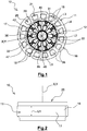
- the figure 1 represents a rotating electrical machine 10 having a polyphase stator 11 surrounding an X-axis rotor 12 to be mounted on a shaft (not shown).
- the stator 11 is intended to be carried by a housing (not shown) configured to rotate the shaft via ball bearings and / or needle as visible for example in the document EP1865200 supra.
- This rotary electrical machine 10 may belong to a compressor used for the refrigerant compression of the air conditioner of a motor vehicle. Alternatively, the machine 10 can operate in alternator mode.
- the rotating electrical machine 10 is advantageously configured to operate at a voltage below 350 volts.
- the stator 11 has a Y axis to be confused with the X axis of the rotor 12 when the machine 10 is in an assembled state.
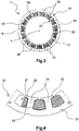
- the stator 11 comprises a body 16 in the form of a packet of laminated sheets having at its outer periphery an annular wall 17, called a yoke, and teeth 18 coming from the inner periphery of the yoke 17, as shown on FIG. the figure 4 .
- These teeth 18 are uniformly distributed circumferentially and extend inward towards the rotor 12, such as a permanent magnet rotor described in more detail below.
- the teeth 18 delimit two by two notches 21, two successive notches 21 being thus separated by a tooth 18. These teeth 18 each have at their free end two flanges 22 extending circumferentially on either side of the tooth 18. The free ends of the teeth 18 delimit, in known manner, an air gap with the outer periphery of the rotor 12 of the rotating electrical machine 10.
- the stator 11 further comprises a three-phase winding having a plurality of coils 26 for forming the different poles of the stator 11.
- Each coil 26 is formed by a plurality of turns surrounding a corresponding tooth 18.
- the coils 26 are made so that one and the same notch 21 receives two half-coils. This gives a winding 25 said type concentrated.
- This winding operation 25 may for example be performed using a centrally hollow needle to allow passage of one or more son in parallel forming the coil 26. This needle moves circumferentially, axially, and radially relative to the stator 11.
- the coil 25 can be realized in situ, that is to say directly around the teeth 18 of the stator 11.
- the coil 25 may be formed on teeth 18 reported which are then fixed on the yoke of the stator 11 via a suitable connection system.
- the stator 11 is equipped with notch insulators 29 taking for example the form of a thin membrane, made of an electrically insulating material and heat conductor. This thin membrane is folded, so that each notch insulator 29 is interposed between a coil 26 and the inner walls of the notches 21 of the stator 11.
- the coils Ui used to form the U phase of the machine As illustrated on the figure 5 , among the coils 26, the coils Ui used to form the U phase of the machine, the coils Vi used to form the phase V of the machine, and the coils Wi used to form the phase W of the machine, i ranging from 1 to N.
- N is in this case 5 but could alternatively have a higher or lower value while remaining at least equal to two.
- Tj corresponds to a tooth 18 of the stator 11 with j ranging from 1 to 15 for a 15-tooth stator.
- the coils are associated alternately with the different phases of the stator 11.
- U, V, W the coil of the tooth T1 is associated with the phase W
- the coil of the tooth T2 is associated with the phase V
- the coil of the tooth T3 is associated with the phase U, and so on.
- the coils 26 of each phase U, V, W are electrically connected in series.
- the U1, U2, U3, U4, U5 coils of the U phase are electrically connected in series.
- the coils V1, V2, V3, V4, V5 of the phase V are electrically connected in series.
- the W1, W2, W3, W4, W5 coils of the W phase are electrically connected in series.
- the phases U, V, W of the machine 10 are advantageously coupled in a triangle.
- the EU input of the phase U is connected with the output SW of the phase W.
- the input EW of the phase W is connected with the output SV of the phase V.
- the input EV of the phase V is connected with the SU output of phase U.
- the product of the number of turns Ns of each coil 26, the axial length L1 of the stator body 16 expressed in millimeters, and the internal diameter L2 of the stator body 16 expressed in millimeters, or the product NsxL1XL2, is between 38998 and 39142.
- the number of turns Ns is between 23 and 37
- the axial length L1 of the stator body 16 is between 17mm and 27mm
- the internal diameter L2 of the stator body 16 is between 62mm and 67mm.
- the curves C1 and C2 respectively corresponding to the length L1 and the yield R are represented in figure 6 . It is observed that the values of the first line do not correspond to an acceptable configuration because they do not make it possible to respect the criterion of compactness (L1 greater than 27mm). In addition, the values in lines 7 and 8 do not allow the imposed performance criterion to be met (R less than 89%).
- the stator body 16 has an external diameter L3 of 94 mm plus or minus 20%.
- the axial length L1 of the stator body 16 is of the order of 20 mm plus or minus 20%.
- the number of turns Ns of each coil 26 is of the order of 32 plus or minus 20%.
- a thickness of the yoke 17 of the stator 11 is of the order of 4.5 mm plus or minus 20%.
- the wire diameter of each coil 26 is of the order 0.8 mm plus or minus 20%.
- the rotor 12 of X axis comprises a body 31 formed by a laminated sheet of pack consisting of an axial stack of ferromagnetic sheets.
- the rotor body 31 comprises a hub 32 mounted on the shaft of the machine and teeth 35 extending radially relative to the hub 32.
- Housing 36 is located between the teeth 35.
- Each housing 36 is delimited by two teeth 35 consecutive, so that there is a circumferential alternation between the teeth 35 and the housings 36.
- At least one permanent magnet 39 is positioned in each housing 36.
- a single magnet 39 positioned within a corresponding housing 36, or two magnets 39 or even more than two magnets per housing 36. stacked axially on each other.
- the magnets 39 extend radially with respect to the X axis of the rotor 12. This results in a rotor configuration 12 with a flux concentration, the lateral faces facing two consecutive magnets 39 being of the same polarity.
- Magnets 39 are preferably rare earth.
- the magnets 39 are made of ferrite according to the applications and the desired power of the rotating electrical machine 10.
- the rotor 12 comprises ten housings 36 and therefore ten poles.
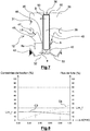
- each tooth 35 comprises two arms 42 of connection to the hub 32, as is clearly visible on the figure 7 .
- Each arm 42 forms a portion of a housing edge 36 of a corresponding magnet 39.
- Each arm 42 comprises a covering portion with a magnet 39 corresponding to the portion of the arm 42 opposite the magnet 39 having a radial length Hu and a thickness e measured in a direction orthoradial with respect to the axis X.
- the ratio between the radial length Hu and the thickness e of an arm 42 is between 1.8 divided by the field B. of the corresponding magnet 39 and 2.16 divided by the field B of the corresponding magnet 39.
- the thickness e of an arm 42 is between 0.3mm and 0.8mm in order to respect the limit at break of the sheet package Lim_r and the maximum permissible leakage flow Lim_f.
- a recess 45 is formed between the two arms 42 of the same corresponding tooth 35.
- the tooth 35 comprises a flared portion 46 extending in the extension of each arm 42 forming a face of the recess 45. This face forms an angle A with a face of the arm 42 forming another face of the recess 45 corresponding to at least 150 °.
- the rotor 12 has an external diameter L4 of between 60 mm and 70 mm and an internal diameter L5 of between 15 and 20 mm (cf. figure 1 ).
- the thickness of each arm 42 is between 0.4 and 0.6 mm, and is preferably of the order of 0.5 mm.
- the length of the useful cover Hu is between 0.7mm and 4.2mm.
- each tooth 35 further comprises a fixing hole 47 adapted to receive a fixing member, such as a rivet, for holding together the laminations of the rotor 12.
- a fixing member such as a rivet
- a gap L6 measured in a plane perpendicular to the X axis between an edge of the fixing hole 47 and an edge of the corresponding recess 45 is constant.
- some teeth 35 of the rotor 12 have a fixing hole 47 but not all.
- lips 50 are implanted on the side of the free end of each tooth 35. These lips 50 extend on either side of each tooth 35. These lips 50 thus constitute means of radial retention of the magnets 39 Alternatively, the housings 36 for the magnets 39 may be closed at their outer periphery.
- Placing members 53 such as flat springs, ensure the plating of the magnets 39 to the corresponding lips 50, as illustrated by FIG. figure 7 .
- Each veneer member 53 is positioned in a corresponding recess 36 between the hub 32 and the corresponding magnet 39.
Landscapes
- Engineering & Computer Science (AREA)
- Power Engineering (AREA)
- Iron Core Of Rotating Electric Machines (AREA)
Abstract
Description
- La présente invention porte sur une machine électrique tournante à configuration améliorée. L'invention trouve une application particulièrement avantageuse dans le domaine des machines électriques tournantes, telles qu'un alternateur ou un moteur électrique. L'invention pourra être utilisée avantageusement avec un compresseur de fluide réfrigérant de climatiseur pour véhicule automobile.
- On connaît des machines électriques comportant un stator et un rotor solidaire d'un arbre assurant la mise en mouvement d'un compresseur à spirale, celle-ci étant désignée sous le nom de "scroll" en anglais. Un tel système comporte deux spirales coopérant entre elles pour pomper et comprimer le fluide réfrigérant. En général, une des spirales est fixe, alors que l'autre se déplace excentriquement sans tourner, de manière à pomper puis emprisonner et comprimer des poches de fluide entre les spires. Un tel système est par exemple décrit dans le document
EP1865200 . - Le rotor de la machine électrique comporte un corps formé par un empilage de feuilles de tôles maintenues sous forme de paquet au moyen d'un système de fixation adapté. Le rotor comporte des pôles formés par exemple par des aimants permanents situés dans des logements ménagés dans la masse magnétique du rotor. Alternativement, dans une configuration dite à pôles "saillants", les pôles sont formés par des bobines enroulées autour de bras du rotor.
- Par ailleurs, le stator comporte un corps réalisé en tôles feuilletées pour diminuer les courants de Foucault. Le corps comporte une paroi annulaire, appelée culasse, et des dents issues de la périphérie interne de la paroi annulaire. Les dents du stator réparties sur la culasse s'étendent vers l'intérieur du stator en direction du rotor. Un entrefer existe entre l'extrémité libre des dents, définissant la périphérie interne du corps du stator, et la périphérie externe du rotor. Les dents définissent avec la culasse des encoches ouvertes vers l'intérieur et destinées à recevoir un bobinage pour formation d'un stator polyphasé par exemple du type triphasé. Ce bobinage pourra par exemple consister en un ensemble de bobines isolées électriquement du corps du stator enroulées chacune autour d'une dent correspondante. On obtient ainsi un bobinage dit de type concentré.
- L'invention vise à améliorer la configuration existante d'une telle machine électrique.
- A cet effet, l'invention a pour objet une machine électrique tournante comprenant:
- un rotor comportant des aimants permanents,
- un stator comportant:
- un corps muni de 15 dents, ledit corps ayant une longueur axiale et un diamètre interne, et
- un bobinage triphasé comportant une pluralité de bobines, chaque bobine formée par une pluralité de spires entourant une dent correspondante,
- le couplage des bobines est du type triangle-série, et
- le produit du nombre de spires de chaque bobine, de la longueur axiale du corps de stator exprimée en millimètres, et du diamètre interne du corps de stator exprimé en millimètres est compris entre 38998 et 39142,
- le nombre de spires étant compris entre 23 et 37, la longueur axiale du corps de stator étant comprise entre 17mm et 27mm, et le diamètre interne du corps de stator étant compris entre 62mm et 67mm.
- Par triangle-série, on entend le fait que les bobines de chaque phase sont montées en série les unes par rapport aux autres et que les ensembles des bobines des phases sont couplés en triangle.
- L'invention permet ainsi d'obtenir un compromis optimum entre le rendement et l'encombrement de la machine électrique tournante. L'invention permet en outre de réduire le poids de la machine et de minimiser le niveau de bruit tout en facilitant la réalisation des opérations de bobinage. On facilite également la connexion entre le bobinage et le connecteur du module de puissance en minimisant le nombre de fils de phase à connecter.
- Selon une réalisation, le corps de stator présente un diamètre externe de 94mm plus ou moins 20%.
- Selon une réalisation, la longueur axiale du corps de stator est de l'ordre de 20mm plus ou moins 20%.
- Selon une réalisation, un nombre de spires de chaque bobine est de l'ordre de 32 plus ou moins 20%.
- Selon une réalisation, une épaisseur de culasse du stator est de l'ordre de 4.5mm plus ou moins 20%.
- Selon une réalisation, un diamètre de fil de chaque bobine est de l'ordre 0.8mm plus ou moins 20%.
- Selon une réalisation, le rotor comprend 10 pôles.
- Selon une réalisation, le rotor comprend:
- un corps comprenant des dents et des logements entre les dents,
- au moins un aimant permanent positionné dans chaque logement,
- le corps comportant en outre un moyeu destiné à être monté sur un arbre,
- chaque dent comportant au moins deux bras de liaison au moyeu, chaque bras formant une portion d'un bord d'un logement d'un aimant permanent correspondant.
- Selon une réalisation, un évidement est formé entre les deux bras d'une même dent.
- Selon une réalisation, au moins une dent comprend un trou de fixation apte à recevoir un organe de fixation et en ce qu'un écart entre un bord du trou de fixation et un bord de l'évidement correspondant est constant.
- Selon une réalisation, le rotor comporte des moyens de retenue radiale des aimants permanents.
- Selon une réalisation, les moyens de retenue radiale sont constitués par des lèvres s'étendant de part et d'autre des dents du rotor.
- Selon une réalisation, ladite machine électrique comporte des organes de plaquage des aimants permanents vers les lèvres correspondantes.
- Selon une réalisation, chaque organe de placage est positionné dans un logement correspondant entre le moyeu et l'aimant permanent correspondant.
- Selon une réalisation, ladite machine électrique tournante est configurée pour fonctionner à une tension inférieure à 350 Volts.
- L'invention sera mieux comprise à la lecture de la description qui suit et à l'examen des figures qui l'accompagnent. Ces figures ne sont données qu'à titre illustratif mais nullement limitatif de l'invention.
- La
figure 1 est une vue en coupe transversale d'une machine électrique tournante selon la présente invention; - La
figure 2 est une vue de côté de la machine électrique tournante selon la présente invention; - La
figure 3 est une vue de dessus du stator de la machine électrique tournante selon la présente invention; - La
figure 4 est une vue en coupe partielle du stator de la machine électrique tournante selon la présente invention; - La
figure 5 est une représentation schématique du couplage en triangle des phases de la machine électrique tournante selon la présente invention; - La
figure 6 est une représentation graphique de l'évolution des paramètres de rendement et de longueur axiale du corps de stator de la machine électrique en fonction du nombre de spires pour chaque bobine; - La
figure 7 est une vue détaillée illustrant la zone de recouvrement entre un aimant et des bras de liaison du rotor de la machine électrique tournante selon la présente invention; - La
figure 8 est une représentation de l'évolution du flux de fuite passant par le bras du rotor et des contraintes mécaniques appliquées sur le paquet de tôles du rotor en fonction de l'épaisseur d'un bras de liaison du rotor. - Les éléments identiques, similaires, ou analogues conservent la même référence d'une figure à l'autre.
- La
figure 1 représente une machine électrique tournante 10 comportant un stator 11 polyphasé entourant un rotor 12 d'axe X destiné à être monté sur un arbre (non représenté). Le stator 11 est destiné à être porté par un carter (non représenté) configuré pour porter à rotation l'arbre via des roulements à billes et/ou à aiguilles comme visible par exemple dans le documentEP1865200 précité. Cette machine électrique tournante 10 pourra appartenir à un compresseur utilisé pour la compression de fluide réfrigérant de climatiseur de véhicule automobile. En variante, la machine 10 pourra fonctionner en mode alternateur. De préférence, la machine électrique tournante 10 est avantageusement configurée pour fonctionner à une tension inférieure à 350 Volts. - Comme on peut le voir sur la
figure 3 , le stator 11 présente un axe Y destiné à être confondu avec l'axe X du rotor 12 lorsque la machine 10 est dans un état assemblé. Le stator 11 comporte un corps 16 sous la forme d'un paquet de tôles feuilletées présentant à sa périphérie externe une paroi annulaire 17, appelé culasse, et des dents 18 issues de la périphérie interne de la culasse 17, tel que cela est représenté sur lafigure 4 . Ces dents 18 sont réparties circonférentiellement de manière régulière et s'étendent vers l'intérieur en direction du rotor 12, tel qu'un rotor à aimants permanents décrit plus en détails ci-après. - Les dents 18 délimitent deux à deux des encoches 21, deux encoches 21 successives étant ainsi séparées par une dent 18. Ces dents 18 présentent chacune à leur extrémité libre deux rebords 22 s'étendant circonférentiellement de part et d'autre de la dent 18. Les extrémités libres des dents 18 délimitent, de manière connue, un entrefer avec la périphérie externe du rotor 12 de la machine électrique tournante 10.
- Le stator 11 comporte en outre un bobinage 25 triphasé comportant une pluralité de bobines 26 pour former les différents pôles du stator 11. Chaque bobine 26 est formée par une pluralité de spires entourant une dent 18 correspondante. Les bobines 26 sont réalisées en sorte qu'une même encoche 21 reçoit deux demi-bobines. On obtient ainsi un bobinage 25 dit de type concentré.
- Les fils des bobines 26, tels que des fils en cuivre ou en aluminium recouverts d'une couche électriquement isolante, comme par exemple de l'émail, sont enroulés chacun autour d'une dent 18. Cette opération de bobinage 25 pourra par exemple être effectuée à l'aide d'une aiguille centralement creuse pour permettre un passage d'un ou plusieurs fils en parallèles formant la bobine 26. Cette aiguille se déplace circonférentiellement, axialement, et radialement par rapport au stator 11. Le bobinage 25 pourra être réalisé in situ, c'est-à-dire directement autour des dents 18 du stator 11. Alternativement, le bobinage 25 pourra être réalisé sur des dents 18 rapportées qui sont ensuite fixées sur la culasse du stator 11 via un système de liaison adapté.
- De préférence, le stator 11 est équipé d'isolants d'encoche 29 prenant par exemple la forme d'une membrane fine, réalisée dans un matériau électriquement isolant et conducteur de chaleur. Cette membrane fine est pliée, en sorte que chaque isolant d'encoche 29 est intercalé entre une bobine 26 et les parois internes des encoches 21 du stator 11.
- Comme cela est illustré sur la
figure 5 , on distingue parmi les bobines 26, les bobines Ui utilisées pour former la phase U de la machine, les bobines Vi utilisées pour former la phase V de la machine, ainsi que les bobines Wi utilisées pour former la phase W de la machine, pour i allant de 1 à N. N vaut en l'occurrence 5 mais pourrait en variante avoir une valeur supérieure ou inférieure tout en restant au moins égale à deux. - Plus précisément, Tj correspond à une dent 18 du stator 11 avec j allant de 1 à 15 pour un stator à 15 dents. Les bobines sont associées alternativement aux différentes phases du stator 11. Ainsi, pour un système à trois phases U, V, W, la bobine de la dent T1 est associée à la phase W, la bobine de la dent T2 est associée à la phase V, la bobine de la dent T3 est associée à la phase U, et ainsi de suite. On retrouve ainsi les bobines 26 associées à une même phase toutes les K dents, K étant le nombre de phases ici égal à trois.
- En outre, les bobines 26 de chaque phase U, V, W sont branchées électriquement en série. Ainsi, les bobines U1, U2, U3, U4, U5 de la phase U sont branchées électriquement en série. Les bobines V1, V2, V3, V4, V5 de la phase V sont branchées électriquement en série. Et les bobines W1, W2, W3, W4, W5 de la phase W sont branchées électriquement en série.
- Les phases U, V, W de la machine 10 sont avantageusement couplées en triangle. Ainsi, l'entrée EU de la phase U est connectée avec la sortie SW de la phase W. L'entrée EW de la phase W est connectée avec la sortie SV de la phase V. L'entrée EV de la phase V est connectée avec la sortie SU de la phase U.
- Afin d'augmenter le rendement de la machine 10, il est nécessaire de réduire sa résistance en augmentant la section bobinable, ainsi que le nombre de spires Ns de chaque bobine 26 et la longueur axiale L1 du corps de stator 16 (cf.
figure 2 ). A iso-taux de remplissage, la réduction du nombre de spires Ns correspond à une augmentation du diamètre de fil. Par ailleurs, pour améliorer la compacité de la machine 10, il est nécessaire de réduire la longueur L1 du corps de stator 16 tout en conservant le même couple. A cet effet, il est nécessaire d'augmenter le nombre de spires Ns. - Afin d'optimiser le compromis entre le rendement et la compacité en ayant un rendement supérieur ou égal à 89% et une longueur axiale L1 du corps de stator 16 inférieure ou égale à 27mm, le produit du nombre de spires Ns de chaque bobine 26, de la longueur axiale L1 du corps de stator 16 exprimée en millimètres, et du diamètre interne L2 du corps de stator 16 exprimé en millimètres, soit le produit NsxL1XL2, est compris entre 38998 et 39142.
- De préférence, le nombre de spires Ns est compris entre 23 et 37, la longueur axiale L1 du corps de stator 16 est comprise entre 17mm et 27mm, et le diamètre interne L2 du corps de stator 16 est compris entre 62mm et 67mm.
- Le tableau ci-dessous présente des exemples de valeurs pour un diamètre interne L2 du corps de stator 16 valant 62mm:
Numéro de ligne Nombre de spires Ns Longueur L1 Rendement R 1 22 28,7 92,9% 2 25 25,2 92,2% 3 28 22,5 91,5% 4 31 20,3 90,7% 5 34 18,5 89,9% 6 37 17,0 89,1% 7 40 15,8 88,2% 8 43 14,7 87,3% - Les courbes C1 et C2 correspondant respectivement à la longueur L1 et au rendement R sont représentées en
figure 6 . On observe que les valeurs de la première ligne ne correspondent pas à une configuration acceptable car elles ne permettent pas de respecter le critère de compacité (L1 supérieur à 27mm). Par ailleurs, les valeurs des lignes 7 et 8 ne permettent pas de respecter le critère de rendement imposé (R inférieur à 89%). - Le tableau ci-dessous présente des exemples de valeurs pour un diamètre interne L2 du corps de stator 16 valant 67mm:
Numéro de ligne Nombre de spires Ns Longueur L1 Rendement R 1 17 34,3 93,4% 2 20 29,2 92,6% 3 23 25,4 91,7% 4 26 22,4 90,8% 5 29 20,1 89,8% 6 32 18,2 88,8% 7 35 16,7 87,7% 8 38 15,4 86,6% - On observe que les valeurs des lignes 1 et 2 ne correspondent pas à des configurations acceptables, car elles ne permettent pas de respecter le critère de compacité (L1 supérieur à 27mm). Par ailleurs, les valeurs des lignes 6, 7, et 8 ne permettent pas de respecter le critère de rendement (R inférieur à 89%).
- Dans un exemple de réalisation particulier, le corps de stator 16 présente un diamètre externe L3 de 94mm plus ou moins 20%. La longueur axiale L1 du corps de stator 16 est de l'ordre de 20mm plus ou moins 20%. Le nombre de spires Ns de chaque bobine 26 est de l'ordre de 32 plus ou moins 20%. Une épaisseur de la culasse 17 du stator 11 est de l'ordre de 4.5mm plus ou moins 20%. Le diamètre de fil de chaque bobine 26 est de l'ordre 0.8mm plus ou moins 20%.
- Par ailleurs, comme cela est visible sur les
figures 1 et7 , le rotor 12 d'axe X comporte un corps 31 formé par un paquet de tôle feuilletée constitué par un empilement axial de tôles ferromagnétiques. Le corps de rotor 31 comprend un moyeu 32 monté sur l'arbre de la machine et des dents 35 s'étendant radialement par rapport au moyeu 32. Des logements 36 sont situés entre les dents 35. Chaque logement 36 est délimité par deux dents 35 consécutives, de sorte qu'il existe une alternance circonférentielle entre les dents 35 et les logements 36. - Au moins un aimant permanent 39 est positionné dans chaque logement 36. Ainsi, il sera possible d'utiliser un aimant 39 unique positionné à l'intérieur d'un logement 36 correspondant, ou deux aimants 39 ou même plus de deux aimants par logement 36 empilés axialement les uns sur les autres.
- Les aimants 39 s'étendent radialement par rapport à l'axe X du rotor 12. On obtient ainsi une configuration de rotor 12 à concentration de flux, les faces latérales en vis-à-vis de deux aimants 39 consécutifs étant de même polarité. Les aimants 39 sont de préférence en terre rare. En variante, les aimants 39 sont en ferrite selon les applications et la puissance recherchée de la machine électrique tournante 10. En l'occurrence, le rotor 12 comporte dix logements 36 et donc dix pôles.
- Par ailleurs, chaque dent 35 comporte deux bras 42 de liaison au moyeu 32, tel que cela est bien visible sur la
figure 7 . Chaque bras 42 forme une portion d'un bord de logement 36 d'un aimant 39 correspondant. Chaque bras 42 comprend une partie de recouvrement avec un aimant 39 correspondant à la partie du bras 42 en vis-à-vis de l'aimant 39 ayant une longueur radiale Hu et une épaisseur e mesurée suivant une direction orthoradiale par rapport à l'axe X. - De préférence, afin d'obtenir un compromis optimum entre les performances magnétiques et la rigidité mécanique du rotor 12, le rapport entre la longueur radiale Hu et l'épaisseur e d'un bras 42 est compris entre 1,8 divisé par le champ B de l'aimant 39 correspondant et 2,16 divisé par le champ B de l'aimant 39 correspondant.
- Sur la
figure 8 où les courbes C3 et C4 représentent respectivement l'évolution des contraintes mécaniques appliquées sur le paquet de tôles du rotor et l'évolution du flux de fuite, l'épaisseur e d'un bras 42 est comprise entre 0.3mm et 0.8mm afin de respecter la limite à la rupture du paquet de tôle Lim_r et le flux de fuite maximum admissible Lim_f. - En outre, un évidement 45 est formé entre les deux bras 42 d'une même dent 35 correspondante. La dent 35 comprend une portion évasée 46 s'étendant dans le prolongement de chaque bras 42 formant une face de l'évidement 45. Cette face forme un angle A avec une face du bras 42 formant une autre face de l'évidement 45 correspondant d'au moins 150°.
- Dans un exemple de réalisation, le rotor 12 présente un diamètre externe L4 compris entre 60mm et 70mm et un diamètre interne L5 comprise entre 15 et 20mm (cf.
figure 1 ). L'épaisseur de chaque bras 42 est comprise entre 0,4 et 0.6mm, et vaut de préférence de l'ordre de 0.5mm. La longueur du recouvrement utile Hu est comprise entre 0.7mm et 4.2mm. - Dans l'exemple représenté sur les
figures 1 et7 , chaque dent 35 comprend en outre un trou de fixation 47 apte à recevoir un organe de fixation, tel qu'un rivet, pour maintenir ensemble les tôles du rotor 12. Afin d'optimiser le passage du flux dans la dent 35, un écart L6 mesuré dans un plan perpendiculaire à l'axe X entre un bord du trou de fixation 47 et un bord de l'évidement 45 correspondant est constant. En variante, certaines dents 35 du rotor 12 comportent un trou de fixation 47 mais pas toutes. - En outre, des lèvres 50 sont implantées du côté de l'extrémité libre de chaque dent 35. Ces lèvres 50 s'étendent de part et d'autre de chaque dent 35. Ces lèvres 50 constituent ainsi des moyens de retenue radiale des aimants 39. En variante, les logements 36 pour les aimants 39 pourront être fermés à leur périphérie externe.
- Des organes de plaquage 53, tel que des ressorts plats, assurent le plaquage des aimants 39 vers les lèvres 50 correspondantes, tel que cela est illustré par la
figure 7 . Chaque organe de placage 53 est positionné dans un logement 36 correspondant entre le moyeu 32 et l'aimant 39 correspondant. - Bien entendu, la description qui précède a été donnée à titre d'exemple uniquement et ne limite pas le domaine de l'invention dont on ne sortirait pas en remplaçant les différents éléments par tous autres équivalents.
- En outre, les différentes caractéristiques, variantes, et/ou formes de réalisation de la présente invention peuvent être associées les unes avec les autres selon diverses combinaisons, dans la mesure où elles ne sont pas incompatibles ou exclusives les unes des autres.
Claims (15)
- Machine électrique tournante (10) comprenant:- un rotor (12) comportant des aimants permanents (39),- un stator (11) comportant:caractérisée en ce que- un corps (16) muni de 15 dents (18), ledit corps (16) ayant une longueur axiale (L1) et un diamètre interne (L2), et- un bobinage (25) triphasé comportant une pluralité de bobines (26), chaque bobine (26) formée par une pluralité de spires entourant une dent (18) correspondante,- le couplage des bobines (26) est du type triangle-série, et- le produit du nombre de spires (Ns) de chaque bobine (26), de la longueur axiale (L1) du corps de stator (16) exprimée en millimètres, et du diamètre interne (L2) du corps de stator (16) exprimé en millimètres est compris entre 38998 et 39142,- le nombre de spires (Ns) étant compris entre 23 et 37, la longueur axiale (L1) du corps de stator (16) étant comprise entre 17mm et 27mm, et le diamètre interne (L2) du corps de stator (16) étant compris entre 62mm et 67mm.
- Machine électrique tournante selon la revendication 1, caractérisée en ce que le corps de stator (16) présente un diamètre externe (L3) de 94mm plus ou moins 20%.
- Machine électrique tournante selon la revendication 1 ou 2, caractérisée en ce que la longueur axiale (L1) du corps de stator (16) est de l'ordre de 20mm plus ou moins 20%.
- Machine électrique tournante selon l'une quelconque des revendications 1 à 3, caractérisée en ce qu'un nombre de spires (Ns) de chaque bobine (26) est de l'ordre de 32 plus ou moins 20%.
- Machine électrique tournante selon l'une quelconque des revendications 1 à 4, caractérisée en ce qu'une épaisseur de culasse du stator (11) est de l'ordre de 4.5mm plus ou moins 20%.
- Machine électrique tournante selon l'une quelconque des revendications 1 à 5, caractérisée en ce qu'un diamètre de fil de chaque bobine (26) est de l'ordre 0.8mm plus ou moins 20%.
- Machine électrique tournante selon l'une quelconque des revendications 1 à 6, caractérisée en ce que le rotor (12) comprend 10 pôles.
- Machine électrique tournante selon l'une quelconque des revendications 1 à 7, caractérisée en ce que le rotor (12) comprend:- un corps (31) comprenant des dents (35) et des logements (36) entre les dents (35),- au moins un aimant permanent (39) positionné dans chaque logement (36),- le corps (31) comportant en outre un moyeu (32) destiné à être monté sur un arbre,- chaque dent comportant au moins deux bras (42) de liaison au moyeu (32), chaque bras (42) formant une portion d'un bord d'un logement (36) d'un aimant permanent (39) correspondant.
- Machine électrique tournante selon la revendication 8, caractérisée en ce qu'un évidement (45) est formé entre les deux bras (42) d'une même dent.
- Machine électrique tournante selon la revendication 9, caractérisée en ce qu'au moins une dent (35) comprend un trou de fixation (47) apte à recevoir un organe de fixation et en ce qu'un écart (L6) entre un bord du trou de fixation (47) et un bord de l'évidement (45) correspondant est constant.
- Machine électrique tournante selon l'une quelconque des revendications 8 à 10, caractérisée en ce que le rotor (12) comporte des moyens de retenue radiale des aimants permanents (39).
- Machine électrique tournante selon la revendication 11, caractérisée en ce que les moyens de retenue radiale sont constitués par des lèvres (50) s'étendant de part et d'autre des dents (35) du rotor (12).
- Machine électrique tournante selon l'une quelconque des revendications 8 à 12, caractérisée en ce qu'elle comporte des organes de plaquage (53) des aimants permanents (39) vers les lèvres (50) correspondantes.
- Machine électrique tournante selon l'une quelconque des revendications 8 à 13, caractérisée en ce que chaque organe de placage (53) est positionné dans un logement (36) correspondant entre le moyeu (32) et l'aimant permanent (39) correspondant.
- Machine électrique tournante selon l'une quelconque des revendications 1 à 14, caractérisée en ce qu'elle est configurée pour fonctionner à une tension inférieure à 350 Volts.
Applications Claiming Priority (1)
| Application Number | Priority Date | Filing Date | Title |
|---|---|---|---|
| FR1751528A FR3063399B1 (fr) | 2017-02-27 | 2017-02-27 | Machine electrique tournante a configuration amelioree |
Publications (1)
| Publication Number | Publication Date |
|---|---|
| EP3373427A1 true EP3373427A1 (fr) | 2018-09-12 |
Family
ID=59520972
Family Applications (1)
| Application Number | Title | Priority Date | Filing Date |
|---|---|---|---|
| EP18158654.6A Withdrawn EP3373427A1 (fr) | 2017-02-27 | 2018-02-26 | Machine électrique tournante à configuration améliorée |
Country Status (4)
| Country | Link |
|---|---|
| US (1) | US20180248434A1 (fr) |
| EP (1) | EP3373427A1 (fr) |
| CN (1) | CN108512332A (fr) |
| FR (1) | FR3063399B1 (fr) |
Cited By (1)
| Publication number | Priority date | Publication date | Assignee | Title |
|---|---|---|---|---|
| FR3094585A1 (fr) * | 2019-03-25 | 2020-10-02 | Valeo Japan Co. Ltd. | Elément isolant de tête de bobine d’un stator de machine électrique tournante, stator et machine électrique tournante correspondants. |
Families Citing this family (3)
| Publication number | Priority date | Publication date | Assignee | Title |
|---|---|---|---|---|
| JP2020054128A (ja) * | 2018-09-27 | 2020-04-02 | 日本電産株式会社 | ロータ、およびモータ |
| CN118659554A (zh) * | 2024-06-13 | 2024-09-17 | 东南大学 | 一种不对称模块化辐条式永磁电机转子 |
| CN120999951B (zh) * | 2025-10-16 | 2025-12-30 | 广东美芝制冷设备有限公司 | 定子组件、永磁同步电机、压缩机和制冷设备 |
Citations (3)
| Publication number | Priority date | Publication date | Assignee | Title |
|---|---|---|---|---|
| EP2372874A2 (fr) * | 2010-03-31 | 2011-10-05 | Valeo Equipements Electriques Moteur | Machine électrique tournante synchrone à aimants permanents et concentration de flux |
| WO2013060960A2 (fr) * | 2011-10-27 | 2013-05-02 | Valeo Equipements Electriques Moteur | Rotor de machine electrique tournante et machine electrique tournante comprenant un rotor |
| WO2014174200A2 (fr) * | 2013-04-23 | 2014-10-30 | Valeo Equipements Electriques Moteur | Élément isolant muni de crochets de maintien de fils de bobinage d'un stator de machine électrique et stator correspondant |
Family Cites Families (4)
| Publication number | Priority date | Publication date | Assignee | Title |
|---|---|---|---|---|
| CN2531572Y (zh) * | 2002-03-21 | 2003-01-15 | 戴国骏 | 电动自行车永磁无刷直流电机 |
| FR2861225B1 (fr) * | 2003-09-05 | 2011-03-11 | Valeo Equip Electr Moteur | Machine electrique tournante polyphasee telle qu'un alternateur ou alterno-demarreur, notamment pour vehicule automobile |
| CN2767036Y (zh) * | 2004-07-27 | 2006-03-29 | 上海申富电机有限公司 | 大功率小型直流弧焊和交流单相同步发电两用机 |
| CN201541189U (zh) * | 2009-09-29 | 2010-08-04 | 泉州泉风电机有限公司 | 单相电容运转异步电机 |
-
2017
- 2017-02-27 FR FR1751528A patent/FR3063399B1/fr not_active Expired - Fee Related
-
2018
- 2018-02-23 US US15/903,552 patent/US20180248434A1/en not_active Abandoned
- 2018-02-26 EP EP18158654.6A patent/EP3373427A1/fr not_active Withdrawn
- 2018-02-27 CN CN201810163817.9A patent/CN108512332A/zh active Pending
Patent Citations (3)
| Publication number | Priority date | Publication date | Assignee | Title |
|---|---|---|---|---|
| EP2372874A2 (fr) * | 2010-03-31 | 2011-10-05 | Valeo Equipements Electriques Moteur | Machine électrique tournante synchrone à aimants permanents et concentration de flux |
| WO2013060960A2 (fr) * | 2011-10-27 | 2013-05-02 | Valeo Equipements Electriques Moteur | Rotor de machine electrique tournante et machine electrique tournante comprenant un rotor |
| WO2014174200A2 (fr) * | 2013-04-23 | 2014-10-30 | Valeo Equipements Electriques Moteur | Élément isolant muni de crochets de maintien de fils de bobinage d'un stator de machine électrique et stator correspondant |
Cited By (2)
| Publication number | Priority date | Publication date | Assignee | Title |
|---|---|---|---|---|
| FR3094585A1 (fr) * | 2019-03-25 | 2020-10-02 | Valeo Japan Co. Ltd. | Elément isolant de tête de bobine d’un stator de machine électrique tournante, stator et machine électrique tournante correspondants. |
| EP3949085A4 (fr) * | 2019-03-25 | 2023-06-07 | Valeo Japan Co., Ltd. | Élément d'isolation pour têtes de bobines d'un stator d'une machine électrique tournante, et stator et machine électrique tournante correspondants |
Also Published As
| Publication number | Publication date |
|---|---|
| CN108512332A (zh) | 2018-09-07 |
| FR3063399B1 (fr) | 2019-06-07 |
| FR3063399A1 (fr) | 2018-08-31 |
| US20180248434A1 (en) | 2018-08-30 |
Similar Documents
| Publication | Publication Date | Title |
|---|---|---|
| WO2004082100A2 (fr) | Machine electrique tournante comportant un stator et deux rotors | |
| FR3063399B1 (fr) | Machine electrique tournante a configuration amelioree | |
| FR3084536A1 (fr) | Rotor de machine electrique avec poles asymetriques | |
| FR2995171A1 (fr) | Flasque de rotor de machine electrique tournante comportant des pales internes de ventilation et rotor de machine electrique associe | |
| EP2209192A1 (fr) | Machine électrique tournante, en particulier pour un démarreur de véhicule automobile | |
| WO2014174200A2 (fr) | Élément isolant muni de crochets de maintien de fils de bobinage d'un stator de machine électrique et stator correspondant | |
| EP1661230A1 (fr) | Machine electrique tournante polyphasee telle qu'un alternateur ou alterno-demarreur, notamment pour vehicule automobile | |
| EP3811505B1 (fr) | Machine électrique tournante ayant une configuration de rotor réduisant les ondulations de couple | |
| FR3054745A1 (fr) | Machine electrique tournante munie d'un interconnecteur a crochets d'ecrouissage | |
| EP3223393B1 (fr) | Machine electrique tournante ayant un ratio de dimensions minimisant les ondulations de couple | |
| EP3580834A1 (fr) | Rotor de machine électrique tournante a configuration améliorée | |
| FR3051295A1 (fr) | Machine electrique tournante a puissance augmentee | |
| EP2078332A1 (fr) | Rotor a griffes muni d'elements ferromagnetiques interpolaires de largeur optimisee et machine tournante equipee d'un tel rotor | |
| WO2017093635A1 (fr) | Rotor a griffes de machine electrique tournante muni d'au moins un chanfrein realise dans un bord de fuite d'une griffe | |
| FR3061370A1 (fr) | Ensemble electromagnetique a structure polyphasee | |
| FR2801142A1 (fr) | Tole de machine tournante electrique a elements rapportes | |
| WO2015145008A1 (fr) | Machine électrique tournante a couplage de phases optimise et procédé de réalisation de bobinage correspondant | |
| FR3054744A1 (fr) | Machine electrique tournante munie d'un interconnecteur auto-denudant | |
| FR3037450A1 (fr) | Machine electrique a commutation de flux a simple excitation | |
| FR2802724A1 (fr) | Stator a dents convexes | |
| FR3059847A1 (fr) | Machine electrique tournante ayant un faible bruit acoustique d'origine electromagnetique | |
| FR2809240A1 (fr) | Machine electrique homopolaire et procede de fabrication d'une telle machine | |
| WO2018042124A1 (fr) | Rotor de machine electrique tournante muni d'au moins une portion deformable pour le remplissage d'une cavité | |
| WO2017093640A1 (fr) | Rotor a griffes de machine electrique tournante muni d'au moins un chanfrein realise dans une griffe | |
| WO2017093634A1 (fr) | Rotor a griffes de machine electrique tournante a performances magnetiques ameliorees |
Legal Events
| Date | Code | Title | Description |
|---|---|---|---|
| PUAI | Public reference made under article 153(3) epc to a published international application that has entered the european phase |
Free format text: ORIGINAL CODE: 0009012 |
|
| STAA | Information on the status of an ep patent application or granted ep patent |
Free format text: STATUS: REQUEST FOR EXAMINATION WAS MADE |
|
| 17P | Request for examination filed |
Effective date: 20180226 |
|
| AK | Designated contracting states |
Kind code of ref document: A1 Designated state(s): AL AT BE BG CH CY CZ DE DK EE ES FI FR GB GR HR HU IE IS IT LI LT LU LV MC MK MT NL NO PL PT RO RS SE SI SK SM TR |
|
| AX | Request for extension of the european patent |
Extension state: BA ME |
|
| GRAP | Despatch of communication of intention to grant a patent |
Free format text: ORIGINAL CODE: EPIDOSNIGR1 |
|
| STAA | Information on the status of an ep patent application or granted ep patent |
Free format text: STATUS: GRANT OF PATENT IS INTENDED |
|
| INTG | Intention to grant announced |
Effective date: 20201028 |
|
| STAA | Information on the status of an ep patent application or granted ep patent |
Free format text: STATUS: THE APPLICATION IS DEEMED TO BE WITHDRAWN |
|
| 18D | Application deemed to be withdrawn |
Effective date: 20210310 |