EP3373135A1 - Information processing device, communication system, and information processing method - Google Patents
Information processing device, communication system, and information processing method Download PDFInfo
- Publication number
- EP3373135A1 EP3373135A1 EP16861969.0A EP16861969A EP3373135A1 EP 3373135 A1 EP3373135 A1 EP 3373135A1 EP 16861969 A EP16861969 A EP 16861969A EP 3373135 A1 EP3373135 A1 EP 3373135A1
- Authority
- EP
- European Patent Office
- Prior art keywords
- processing apparatus
- information processing
- unit
- setup
- information
- Prior art date
- Legal status (The legal status is an assumption and is not a legal conclusion. Google has not performed a legal analysis and makes no representation as to the accuracy of the status listed.)
- Withdrawn
Links
Images











Classifications
-
- G—PHYSICS
- G06—COMPUTING OR CALCULATING; COUNTING
- G06F—ELECTRIC DIGITAL DATA PROCESSING
- G06F8/00—Arrangements for software engineering
- G06F8/60—Software deployment
- G06F8/65—Updates
-
- G—PHYSICS
- G06—COMPUTING OR CALCULATING; COUNTING
- G06F—ELECTRIC DIGITAL DATA PROCESSING
- G06F3/00—Input arrangements for transferring data to be processed into a form capable of being handled by the computer; Output arrangements for transferring data from processing unit to output unit, e.g. interface arrangements
- G06F3/01—Input arrangements or combined input and output arrangements for interaction between user and computer
- G06F3/048—Interaction techniques based on graphical user interfaces [GUI]
- G06F3/0487—Interaction techniques based on graphical user interfaces [GUI] using specific features provided by the input device, e.g. functions controlled by the rotation of a mouse with dual sensing arrangements, or of the nature of the input device, e.g. tap gestures based on pressure sensed by a digitiser
- G06F3/0488—Interaction techniques based on graphical user interfaces [GUI] using specific features provided by the input device, e.g. functions controlled by the rotation of a mouse with dual sensing arrangements, or of the nature of the input device, e.g. tap gestures based on pressure sensed by a digitiser using a touch-screen or digitiser, e.g. input of commands through traced gestures
- G06F3/04883—Interaction techniques based on graphical user interfaces [GUI] using specific features provided by the input device, e.g. functions controlled by the rotation of a mouse with dual sensing arrangements, or of the nature of the input device, e.g. tap gestures based on pressure sensed by a digitiser using a touch-screen or digitiser, e.g. input of commands through traced gestures for inputting data by handwriting, e.g. gesture or text
-
- G—PHYSICS
- G06—COMPUTING OR CALCULATING; COUNTING
- G06F—ELECTRIC DIGITAL DATA PROCESSING
- G06F3/00—Input arrangements for transferring data to be processed into a form capable of being handled by the computer; Output arrangements for transferring data from processing unit to output unit, e.g. interface arrangements
- G06F3/01—Input arrangements or combined input and output arrangements for interaction between user and computer
- G06F3/03—Arrangements for converting the position or the displacement of a member into a coded form
- G06F3/033—Pointing devices displaced or positioned by the user, e.g. mice, trackballs, pens or joysticks; Accessories therefor
- G06F3/0354—Pointing devices displaced or positioned by the user, e.g. mice, trackballs, pens or joysticks; Accessories therefor with detection of two-dimensional [2D] relative movements between the device, or an operating part thereof, and a plane or surface, e.g. 2D mice, trackballs, pens or pucks
- G06F3/03547—Touch pads, in which fingers can move on a surface
-
- G—PHYSICS
- G06—COMPUTING OR CALCULATING; COUNTING
- G06F—ELECTRIC DIGITAL DATA PROCESSING
- G06F3/00—Input arrangements for transferring data to be processed into a form capable of being handled by the computer; Output arrangements for transferring data from processing unit to output unit, e.g. interface arrangements
- G06F3/01—Input arrangements or combined input and output arrangements for interaction between user and computer
- G06F3/03—Arrangements for converting the position or the displacement of a member into a coded form
- G06F3/041—Digitisers, e.g. for touch screens or touch pads, characterised by the transducing means
- G06F3/042—Digitisers, e.g. for touch screens or touch pads, characterised by the transducing means by opto-electronic means
- G06F3/0421—Digitisers, e.g. for touch screens or touch pads, characterised by the transducing means by opto-electronic means by interrupting or reflecting a light beam, e.g. optical touch-screen
-
- G—PHYSICS
- G06—COMPUTING OR CALCULATING; COUNTING
- G06F—ELECTRIC DIGITAL DATA PROCESSING
- G06F3/00—Input arrangements for transferring data to be processed into a form capable of being handled by the computer; Output arrangements for transferring data from processing unit to output unit, e.g. interface arrangements
- G06F3/01—Input arrangements or combined input and output arrangements for interaction between user and computer
- G06F3/03—Arrangements for converting the position or the displacement of a member into a coded form
- G06F3/041—Digitisers, e.g. for touch screens or touch pads, characterised by the transducing means
- G06F3/042—Digitisers, e.g. for touch screens or touch pads, characterised by the transducing means by opto-electronic means
- G06F3/0425—Digitisers, e.g. for touch screens or touch pads, characterised by the transducing means by opto-electronic means using a single imaging device like a video camera for tracking the absolute position of a single or a plurality of objects with respect to an imaged reference surface, e.g. video camera imaging a display or a projection screen, a table or a wall surface, on which a computer generated image is displayed or projected
-
- G—PHYSICS
- G06—COMPUTING OR CALCULATING; COUNTING
- G06F—ELECTRIC DIGITAL DATA PROCESSING
- G06F3/00—Input arrangements for transferring data to be processed into a form capable of being handled by the computer; Output arrangements for transferring data from processing unit to output unit, e.g. interface arrangements
- G06F3/01—Input arrangements or combined input and output arrangements for interaction between user and computer
- G06F3/048—Interaction techniques based on graphical user interfaces [GUI]
- G06F3/0481—Interaction techniques based on graphical user interfaces [GUI] based on specific properties of the displayed interaction object or a metaphor-based environment, e.g. interaction with desktop elements like windows or icons, or assisted by a cursor's changing behaviour or appearance
- G06F3/0483—Interaction with page-structured environments, e.g. book metaphor
-
- G—PHYSICS
- G06—COMPUTING OR CALCULATING; COUNTING
- G06F—ELECTRIC DIGITAL DATA PROCESSING
- G06F8/00—Arrangements for software engineering
- G06F8/70—Software maintenance or management
- G06F8/71—Version control; Configuration management
-
- G—PHYSICS
- G06—COMPUTING OR CALCULATING; COUNTING
- G06F—ELECTRIC DIGITAL DATA PROCESSING
- G06F9/00—Arrangements for program control, e.g. control units
- G06F9/06—Arrangements for program control, e.g. control units using stored programs, i.e. using an internal store of processing equipment to receive or retain programs
- G06F9/44—Arrangements for executing specific programs
- G06F9/445—Program loading or initiating
- G06F9/44505—Configuring for program initiating, e.g. using registry, configuration files
-
- G—PHYSICS
- G06—COMPUTING OR CALCULATING; COUNTING
- G06F—ELECTRIC DIGITAL DATA PROCESSING
- G06F3/00—Input arrangements for transferring data to be processed into a form capable of being handled by the computer; Output arrangements for transferring data from processing unit to output unit, e.g. interface arrangements
- G06F3/14—Digital output to display device ; Cooperation and interconnection of the display device with other functional units
- G06F3/147—Digital output to display device ; Cooperation and interconnection of the display device with other functional units using display panels
Definitions
- the present invention relates to an information processing apparatus, a communication system, and a method for processing information.
- a known electronic whiteboard is formed such that a touch panel is installed on a large-sized flat panel display.
- This electronic whiteboard displays a screen playing a role of a whiteboard, captures trajectory of an electronic pen, a finger, or the like through the touch panel, and draws the trajectory on a screen as handwritten contents. Therefore, a user can use the screen like a whiteboard.
- the electronic whiteboard which can be coupled to a personal computer, it is possible to cause the electronic whiteboard to display a screen that is the same as the personal computer, draw handwritten contents on this screen, or operate the personal computer by the electronic whiteboard in accordance with information input from a touch panel.
- Patent Document 1 discloses a network synchronization system including a first apparatus and a second apparatus.
- the first apparatus includes a synchronization shared memory means.
- the second apparatus includes a setup information means storing personal setup information for each user and a synchronization control means updating the personal setup information stored by the setup information means for each user to be the newest personal setup information.
- the synchronization control means acquires common update information that is common to multiple information processing apparatuses and stored by the synchronization shared memory means.
- the software is subjected to be version upgrade in accordance with an addition, revision, or the like of a function by a maker. Then, an administrator or the like of the electronic whiteboard may obtain software subjected to version upgrade and install the obtained software onto the electronic whiteboard.
- setup contents related to the operation of the electronic whiteboard are different in accordance with different versions of the software.
- setup contents are different, it is not preferable to synchronize setups between multiple electronic whiteboards.
- burden for the administrator becomes heavy as the number of the electronic whiteboards increases.
- the version of the software is not considered when the second apparatus causes the first apparatus to synchronize the personal setup information.
- the object of the present invention is to provide the information processing apparatus, in which the version of the software is considered at a time of synchronizing the setup.
- the present invention includes an information processing apparatus providing a function by a program installed on the information processing apparatus and behaving based on setup information related to an operation including a communication information memory unit configured to store communication information for communicating with another information processing apparatus, a first determining unit configured to communicate with the another information processing apparatus using the communication information and determine whether a version of the program installed on the information processing apparatus matches a version of the pr installed on the another information processing apparatus, and a setup information acquiring unit configured to communicate with the another information processing apparatus using the communication information and acquire the setup information from the another information processing apparatus in a case where the first determining unit determines that the version of the software installed on the information processing apparatus matches the version of the software installed on the another information processing apparatus.
- FIG. 1A illustrates an example of a network structure of an image processing system of the embodiment.
- An image processing system 1 has a network structure of a tree structure.
- multiple electronic whiteboards form a hierarchical structure, in which stepwise layers are formed by the electronic whiteboard 2p of a parent apparatus, the electronic whiteboard 2c of a child apparatus, and the electronic whiteboard 2g of a grandchild apparatus.
- an electronic whiteboard 2 designates an arbitrary one from among the electronic whiteboards 2p, 2c, and 2g.
- the tree structure is one type of the hierarchical structure, and branching from a node (an electronic whiteboard 2) to another node (an electronic whiteboard 2) is repeated.
- the child apparatus-1 to child apparatus-3 start to communicate with the parent apparatus 2p.
- Setup information held by the parent apparatus 2p is acquired by the child apparatus-1, and the acquired setup information is set to the child apparatus-1 itself.
- the setup information is set to the child apparatuse-2 and the child apparatuse-3 themselves in a manner similar to the above.
- Grandchild apparatus-1 to grandchild apparatus-3 (reference symbols 2g) start communications with the child apparatus-1, acquires the setup information held by the child apparatus-1, and sets the acquired setup information to the grandchild apparatus-1.
- the setup information is set to the grandchild apparatuse-2 and the grandchild apparatuse-3 themselves in a manner similar to the above.
- FIG. 1B illustrates a comparative example compared with the network structure of this embodiment.
- the parent apparatus 2p sets the setup information to the child apparatus-1 to child apparatus-3
- the child apparatus-1 sets the setup information to the grandchild apparatus-1 to grandchild apparatus-3.
- the parent apparatus 2p is required to set the setup information to the child apparatus-1-3
- the child apparatus-1 is required to set the setup information to the grandchild apparatus-1 to grandchild apparatus-3. Therefore, a load on one electronic whiteboard 2 is heavy.
- the one electronic whiteboard 2 communicates with only the electronic whiteboard 2 immediately above the own electronic whiteboard 2. Therefore, it is possible to suppress a load on each electronic whiteboard 2 required at a time of synchronizing the setup information. Further, each electronic whiteboard 2 is not required to hold information related to update of the setup information of the electronic whiteboard 2 located immediately below the own electronic whiteboard 2. The meaning of the "electronic whiteboard immediately above” and the "electronic whiteboard immediately above” will be described in detail later.
- the electronic whiteboard 2 providing the setup information conducts a process of sending the setup information in response to the request from the electronic whiteboard 2 immediately below the own electronic whiteboard 2. Thus, this process is relatively low on the load.
- the electronic whiteboard 2 can have the multiple electronic whiteboards 2 (three in FIG. 2 ) immediately below the own electronic whiteboard 2. Said differently, it is not necessary to couple the electronic whiteboard 2 in series (daisy chain). With a relatively light load and within a relatively short time, the electronic whiteboard 2 can synchronize the setup information.
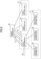
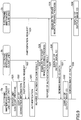
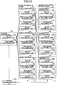
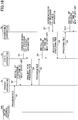
- FIG. 2 illustrates an example schematically explaining a process of considering a version of a program at a time of synchronizing setup information.
- the electronic whiteboard 2 checks whether the version of the program is the same as that of the other electronic whiteboard 2 located immediately above the electronic whiteboard 2.
- a procedure until the synchronization is briefly explained.
- the electronic whiteboard 2 is enabled to synchronize the setup information with the different setup information held by the other electronic whiteboard 2 located immediately above the electronic whiteboard 2 even if the different setup information has items different from items of the setup information because the versions of the programs are different. Further, the electronic whiteboard 2 having a version of the program from the version of the program of the other electronic whiteboard 2 located immediately above the electronic whiteboard 2 is enabled to synchronize the setup information after conducting version upgrade for the program of the electronic whiteboard 2.
- each electronic whiteboard 2 is enabled to synchronize not only the setup information but also the versions of the programs. Therefore, after the administrator conducts the version upgrade of the program of the parent apparatus, all electronic whiteboards 2 are enabled to conduct the version upgrade.
- Software is a procedure related to an operation of a computer and information processed by the computer.
- a program is one of what is called the software.
- the program is information designating a function to be implemented by the electronic whiteboard 2 using a language decodable by a computer.
- the program can be said to be function designation descripting information.
- the program may be specifically called an application program, firmware, an operating system (OS), or the like. However, the program is not limited to these.
- the software and the program may not be exactly differentiated. In the explanation of the embodiment, the term "program" may be used so as to include the software and the program for convenience.
- the setup information is information designating the content of setups related to operation of the electronic whiteboard 2.
- the setup information includes, for example, information indicating the content of the setup for the electronic whiteboard 2 to properly behave, information indicating the content of the setup to permit or limit the operation of the electronic whiteboard 2, information indicating the content of the setup of on/off of various functions, and information indicating the content of the setup for communicating with the Internet and another apparatus.
- the contents of the setup information are specifically described later with reference to FIGs. 16A and 16B .
- the network structure of the tree structure has at least three hierarchies.
- the network structure may have only two hierarchies. It is preferable that the network structure of the tree structure has at least three hierarchies.
- the network structure may include a branch of two or less hierarchy.
- the number of the electronic whiteboards 2 included in one hierarchy is not limited to three, and properly determined in consideration of the total number of the electronic whiteboards 2 and the depth of the hierarchies.
- a layer of the child apparatus-1 to child apparatus-3 is referred to as a child apparatus layer C
- a layer of the grandchild apparatus-1 to grandchild apparatus-3 is referred to as a grandchild apparatus layer G.
- the electronic whiteboard 2 directly at an upper position such as the parent apparatus 2p relative to the child apparatus-1 is referred to as an "immediately above electronic whiteboard 2”
- the electronic whiteboard 2 directly at a lower position such as the child apparatus-1 relative to the parent apparatus 2p is referred to as an "immediately below electronic whiteboard 2".
- the child apparatus-1 to child apparatus-3 and the grandchild apparatus-1 to grandchild apparatus-3, and electronic whiteboards at further lower positions relative to the parent apparatus 2p are referred to as a "relatively lower electronic whiteboard 2".
- the electronic whiteboards 2 of the child apparatus-1 and the parent apparatus 2p relative to the grandchild apparatus-1 are referred to as a "relatively upper electronic whiteboard 2".
- FIG. 3 illustrates an overall structure of the image processing system 1 of this embodiment.
- two electronic whiteboards 2a and 2b, electronic pens 4a and 4b attached thereto, and so on are illustrated.
- At least three electronic whiteboards, electronic pens attached thereto, and so on may be used in the image processing system 1 of this embodiment.
- the image processing system 1 includes multiple electronic whiteboards 2a and 2b, multiple electronic pens 4a and 4b, Universal Serial Bus (USB) memories 5a and 5b, notebook personal computer (PC) 6a and 6b, television (video) meeting terminals 7a and 7b, and a PC 8. Further, the electronic whiteboards 2a and 2b and the PC 8 are coupled through a communication network 9 so as to be communicable. Further, displays 3a and 3b are respectively provided with the multiple electronic whiteboards 2a and 2b.
- USB Universal Serial Bus
- the electronic whiteboard 2a can cause an image drawn by an event (touching the display 3a with the pen nib or the pen tail of the electronic pen 4a) to be displayed on the display 3a.
- the electronic whiteboard 2a can change an image displayed on a display 3a based on the event (gesture of enlargement, reduction, page turning, or the like) caused by the electronic pen 4a, a user's hand Ha, or the like.
- the USB memory 5a can be coupled to the electronic whiteboard 2a.
- the electronic whiteboard 2a is enabled to read an electronic file of Portable Document Format (PDF) from the USB memory 5a or record an electronic file in the USB memory 5a.
- PDF Portable Document Format
- the notebook PC 6a is coupled to the electronic whiteboard 2a through a cable 10a1 enabling communications using standards of DisplayPort ("DisplayPort” is a registered trademark), Digital Visual Interface (DVI), High-Definition Multimedia Interface (HDMI, "HDMI” is a registered trademark), and Video Graphics Array (VGA).
- DisplayPort is a registered trademark
- DVI Digital Visual Interface
- HDMI High-Definition Multimedia Interface
- VGA Video Graphics Array
- the electronic whiteboard 2a causes the event to occur by a touch on the display 3a, and sends event information indicative of the event to the notebook PC 6a in a manner similar to an event from an input apparatus such as a mouse and a keyboard.
- a teleconference (video conference) terminal 7a is coupled to the electronic whiteboard 2a through a cable 10a2 enabling the communications using the above standards.
- the notebook PC 6a and the teleconference terminal 7a may communicate with the electronic whiteboard 2a in conformity with various wireless communication protocols such as Bluetooth ("Bluetooth" is a registered trademark).
- the electronic whiteboard 2b having the display 3b, the electronic pen 4b, the USB memory 5b, the notebook PC 6b, the teleconference terminal 7b, a cable 10b1, and a cable 10b2 are used in a manner similar thereto. Further, the electronic whiteboard 2b can change the image displayed on the display 3b based on the event occurred by the user's hand Hb.
- an image drawn on the display 3a of the electronic whiteboard 2a at one location is displayed on the display 3b of the electronic whiteboard 2b at another location.
- an image drawn on the display 3b of the electronic whiteboard 2b at the other location is displayed on the display 3a of the electronic whiteboard 2a at the one location.
- an arbitrary electronic whiteboard from among multiple electronic whiteboards is referred to as the "electronic whiteboard 2".
- An arbitrary display from among multiple displays is referred to as a "display 3".
- An arbitrary electronic pen from among multiple electronic pens is referred to as an “electronic pen 4".
- An USB memory from among multiple USB memories is referred to as a "USB memory 5".
- An arbitrary notebook PC from among multiple notebook PCs is referred to as a "notebook PC 6”.
- An arbitrary teleconference terminal from among multiple teleconference terminals is referred to as a "teleconference terminal 7".
- An arbitrary hand from among multiple users' hands is referred to as a "hand H”.
- An arbitrary cable from among multiple cables is referred to as a "cable 10".
- the electronic whiteboard is described as an example of the image processing apparatus.
- the image processing apparatus is not limited to the electronic whiteboard.
- Other examples of the image processing apparatus are a digital signage, a telestrators, a remote image (screen image) diagnosing apparatus, and so on.
- the notebook PC 6 is Described next is the notebook PC 6 as an example of the information processing terminal.
- the information processing terminal is not limited to the notebook PC.
- Other examples of the information processing terminal are a desktop PC, a tablet PC, a Personal Digital Assistant (PDA), a digital video camera, a digital camera, a game machine, or the like, which can supply image frames.
- PDA Personal Digital Assistant
- the communication network 9 may be any one of the Internet, a local area network (LAN), a mobile phone communication network, and so on or a combination of a part or all of these.
- the USB memory is described as an example of a recording medium.
- the recording medium is not limited to the USB memory.
- Other examples of the recording medium are various recording mediums such as a secure digital (SD) card.
- SD secure digital
- FIG. 4 illustrates an example of the hardware structure of the electronic whiteboard.
- the electronic whiteboard 2 includes a central processing unit (CPU) 101 controlling entire operation of the electronic whiteboard 2, a read-only memory (ROM) storing a program used to drive the CPU 101, a random access memory (RAM) 103 used as an work area of the CPU 101, a solid state drive (SSD) 104 storing various data such as a program for the electronic whiteboard 2, a network controller 105 controlling communications with the communication network 9, and an external memory controller 106 controlling communications with the USB memory 5.
- CPU central processing unit
- ROM read-only memory
- RAM random access memory
- SSD solid state drive
- the electronic whiteboard 2 includes a capture device 111 for causing the display of the notebook PC 6 to display screen image information as a still image or a moving image, a Graphics Processing Unit (GPU) 112 exclusively handling graphics, and display controller 113 of controlling and managing a screen display so as to output on output image from the GPU 112 to the display 3 and the teleconference terminal 7.
- a capture device 111 for causing the display of the notebook PC 6 to display screen image information as a still image or a moving image
- a Graphics Processing Unit (GPU) 112 exclusively handling graphics
- display controller 113 of controlling and managing a screen display so as to output on output image from the GPU 112 to the display 3 and the teleconference terminal 7.
- the electronic whiteboard 2 includes a sensor controller 114 for controlling a process of a touch sensor 115, and the touch sensor for detecting a touch of the electronic pen 4 or the user's hand to the display 3.
- This touch sensor 115 performs an input of a coordinate and a detection of the coordinate by an infrared ray interrupting method. This method of performing the input of the coordinate and the detection of the coordinate are implemented by two light receiving and detecting apparatuses installed at both ends of the upper sides of the display 3.
- the two light receiving and detecting apparatuses emit multiple infrared rays in parallel with the display 3, the multiple infrared rays are reflected by a reflecting part provided in the periphery of the display 3, and the light receiving element receives the light returning through the same light path as the light path of the emitted infrared ray.
- the touch sensor 115 outputs identification (ID) of the infrared rays that are emitted by the two light receiving and detecting apparatuses and interrupted by an object, and the sensor controller 114 specifies a coordinate position where the object touches the electronic whiteboard. All IDs described below are examples of the identification information.
- the touch sensor 115 may not be limited to the sensor of the infrared ray cutting off touch panel.
- Other examples are various detecting means such as a touch panel of a capacitive sensing type that detect a change of electrostatic capacity to specify a touch position, a touch panel of a resistive film type that specifies the touch position using a voltage change in two facing resistive films, and a touch panel of an electromagnetic induction type that detects electromagnetic induction caused by a contact of a touching object and specifies the touch position.
- the electronic whiteboard 2 has an electronic pen controller 116.
- This electronic pen controller 116 communicates with the electronic pen 4 to determine whether there is a touch of a pen nib or a pen tail on the display 3.
- the electronic pen controller 116 may determine whether there is a touch of a part of the electronic pen 4 grasped by the user or another part of the electronic pen 4 in addition to the touch of the pen nib and the pen tail.
- the electronic whiteboard 2 has a bus line 120 such as an address bus and a data bus for electrically couple the CPU 101, the ROM 102, the RAM 103, the SSD 104, the network controller 105, the external memory controller 106, the capture device 111, the GPU 112, the sensor controller 114, and the electronic pen controller 116 as illustrated in FIG. 3 .
- a bus line 120 such as an address bus and a data bus for electrically couple the CPU 101, the ROM 102, the RAM 103, the SSD 104, the network controller 105, the external memory controller 106, the capture device 111, the GPU 112, the sensor controller 114, and the electronic pen controller 116 as illustrated in FIG. 3 .
- the program for the electronic whiteboard 2 may be recorded in a recording medium such as a CD-ROM readable by a computer and distributed.
- FIG. 5 is an example of a functional block diagram of the electronic whiteboard 2.
- the electronic whiteboard 2 implements various functional structures illustrated in FIG. 5 using the hardware structure illustrated in FIG. 4 and the program.
- the electronic whiteboard 2 may be a "hosting apparatus” firstly starting a remote sharing process and also a "participating apparatus" participating later in a remote sharing process, which has already been started.
- the electronic whiteboard 2 roughly has both of a client unit 20 and a server unit 90.
- the client unit 20 and the server unit 90 are functions implemented in the casing of the single electronic whiteboard 2.
- the client unit 20 and the server unit 90 are implemented by this electronic whiteboard 2.
- the electronic whiteboard 2 is the participating apparatus, the client unit 20 is implemented by this electronic whiteboard 2.
- the server unit 90 is not implemented by the electronic whiteboard 2.
- the client unit 20 of the electronic whiteboard 2a communicates with the client unit 20 of the client unit 20 of the electronic whiteboard 2a communicates with the client unit 20 of the other electronic whiteboard 2b through the server unit 90 implemented inside the electronic whiteboard 2a.
- Electronic whiteboard 2b through the server unit 90 implemented inside the electronic whiteboard 2a.
- the client unit 20 of the electronic whiteboard 2b communicates with the client unit 20 of the other electronic whiteboard 2a through the server unit 90 implemented inside the other electronic whiteboard 2a.
- the client unit 20 includes a screen image acquiring unit 21, a coordinate detecting unit 22, an automatic adjusting unit 23, a touch detecting unit 24, an event sorting unit 25, an operation processing unit 26, a gesture processing unit 27, a screen image superposing unit 28, an image processing unit 30, and a communication controlling unit 60.
- the screen image acquiring unit 21 acquires an output image from a screen image outputting apparatus coupled to the cable 10.
- the screen image acquiring unit 21 analyzes this image signal, derives image information such as the resolution of an image frame being a display image of the screen image outputting apparatus generated by the image signal and the frequency of update of the image frame, and outputs the image information to the image acquiring unit 31.
- the coordinate detecting unit 22 detects a coordinate position of an event (operation that the user's hand touches the display or the like) caused by the user on the display 3.
- the coordinate detecting unit 22 also detects an area that the user's hand touches the display 3.
- the coordinate detecting unit 22 for detecting the coordinate by an optical sensor type adjusts a parameter at a time of processing the image of a sensor camera so that the automatic adjusting unit 23 is activated at a time of activating (or at a time of restarting) the electronic whiteboard 2 and the coordinate detecting unit 22 can output an appropriate value.
- the touch detecting unit 24 detects an event (operation of pushing the pen nib or the pen tail of the electronic pen 4 against the display to cause the pen nib or the pen tail to touch the event.
- the event sorting unit 25 sorts the coordinate position of the event detected by the coordinate detecting unit 22 and a detection result detected by the touch detecting unit 24 into various events such as a stroke draw, a user interface (UI) operation, and a gesture operation.
- the "stroke draw” is an event in which the user causes the electronic pen 4 to touch the display 3, the electronic pen 4 is moved while the electronic pen 4 touches the display 3, and the electronic pen 4 is moved away from the display 3, in a case where a stroke image (B) (described below and illustrated in FIG. 8 ) is displayed on the display 3.
- a stroke image (B) (described below and illustrated in FIG. 8 )
- alphabetical letters "S", "T", or the like are drawn on the display using the stroke draw.
- This "stroke draw” includes not only the event of drawing the image but also an event of deleting the already drawn image and an event of editing the drawn image.
- the "UI operation” is an event in which the user touches a predetermined position with the electronic pen 4 or the user's hand H in a case where an UI image (A) (described below and illustrated in FIG. 8 ) is displayed on the display 3.
- an UI image A (described below and illustrated in FIG. 8 ) is displayed on the display 3.
- this UI operation for example, the color, the width, or the like of a line drawn by the electronic pen 4 is set.
- the "gesture operation” is an event that the user's hand H touches or moves on the display 3 in a case where the stroke image (B) illustrated in FIG. 8 and described later is displayed on the display 3.
- this gesture operation for example, when the user moves the user's hand H while the user's hand H touches the display 3, the user can enlarge or reduce the image, change a display area, and change the opened page.
- the operation processing unit 26 executes various operations in accordance with elements of the UI on which the event is performed based on the event determined to be the UI operation by the event sorting unit.
- the elements of this UI are, for example, a button, a list, a check box, a text box, and so on.
- the gesture processing unit 27 executes an operation corresponding to what determined by the event sorting unit to be the gesture operation.
- the screen image superposing unit 28 causes an image superposed by the display superposing unit 36 described later to be displayed on the display unit 29.
- the display unit 29 performs a display function implemented by the display 3.
- the screen image superposing unit 28 displays a screen image received from a screen image outputting apparatus (a notebook PC 6 and so on) and additionally another screen image received from another screen image outputting apparatus (a teleconference terminal 7 and so on) using a so-called picture-in-picture function. Further, the screen image superposing unit 28 can perform a changeover where a screen image displayed in a part of the display unit 29 using the picture-in-picture function is caused to be displayed on the entire display unit 29.
- the image processing unit 30 performs a superposing process of superposing various image layers illustrated in FIG. 8 .
- This image processing unit 30 includes an image acquiring unit 31, a stroke processing unit 32, a UI image generating unit 33, a background generating unit 34, a layout administering unit 35, a display superposing unit 36, a page processing unit 37, a file processing unit 40, a page data memory unit 300, and a remote license administering table 310.
- the image acquiring unit 31 acquires various frames as images from screen images acquired by the screen image acquiring unit 21.
- the image acquiring unit 31 outputs data of the images to the page processing unit 37. These images correspond to output images (C) from the screen image outputting apparatus (the notebook PC 6 or the like) illustrated in FIG. 8 .
- the stroke processing unit 32 draws images, deletes the drawn images, and edits the drawn images based on an event related to the stroke draw allocated by the event sorting unit 25.
- An image obtained by this stroke draw corresponds to the stroke image (B) illustrated in FIG. 8 .
- Results of drawing, deleting, and editing the image based on this stroke draw are stored in an operation data memory unit 840.
- the UI image generating unit 33 generates an UI image previously set in the electronic whiteboard 2. This UI image corresponds to an UI image (A) illustrated in FIG.8 .
- the background generating unit 34 receives media data from among page data read by the page processing unit 37 from the page data memory unit 300. The background generating unit 34 outputs the received media data to the display superposing unit 36. Further, the image obtained by the media data corresponds to a background image (D) illustrated in FIG. 8 .
- the pattern of the background image (D) is a solid color, a grid display, or the like.
- the layout administering unit 35 administers layout information indicative of layouts of the images output from the image acquiring unit 31, the stroke processing unit 32, the UI image generating unit 33 (or the background generating unit 34) to the display superposing unit 36. With this, the layout administering unit 35 can instruct the display superposing unit 36 to display the output image at which position inside the UI image (A) and the background image (D) or not to display.
- the display superposing unit 36 performs layout of images output from the image acquiring unit 31, the stroke processing unit 32, and the UI image generating unit 33 (the background generating unit 34) based on the layout information output from the layout administering unit 35.
- the page processing unit 37 combines data of the stroke image (B) with data of the output image (C) into one page data and stores the one page data in the page data memory unit 300.
- the data of the stroke image (B) forms a part of page data as stroke array data (each stroke data) indicated by a stroke array data ID in Table 1 described below.
- the data of the output image (C) is media data identified by a media data ID in Table 1 and forms a part of the page data. This media data is read out of the page data memory unit 300 and then handled as data of the background image (D).
- the page processing unit 37 sends the media data of the once stored page data to the display superposing unit 36 through the background generating unit 34 to make the screen image superposing unit 28 display the background image (D) on the display 30 again. Further, the page processing unit 37 returns the stroke array data (each stroke data) of the page data to the stroke processing unit 32 to enable the stroke to be re-edited. Further, the page processing unit 37 can delete or copy the page data.
- the page processing unit 37 stores the page data in the page data memory unit 300, the data of the output image (C) displayed on the display 3 is once stored in the page data memory unit 300, and thereafter read from the page data memory unit 300 as the media data indicating the background image (D). Then, the page processing unit 37 outputs the stroke data indicating the stroke image (B) from among the page data read from the page data memory unit 300 to the stroke processing unit 32. The page processing unit 37 outputs the media data, which are included in the page data memory unit 300 and indicates the background image (D), to the background generating unit 34.
- the display superposing unit 36 superposes the output image (C) from the image acquiring unit 31, the stroke image (B) from the stroke processing unit 32, the UI image (A) from the UI image generating unit 33, and the background image (D) from the background generating unit 34 in accordance with the layout designated by the layout administering unit 35.
- the UI image (A), the stroke image (B), the output image (C), and the background image (D) superpose, in an order of enabling the user to see the images even though the images overlap.
- the display superposing unit 36 switches between the images (C) and (D) illustrated in FIG. 8 , and exclusively superposes the switched image on the images (A) and (B).
- the display superposing unit 36 performs a process of enlarging the display, a process of reducing the display, and a process of moving the display area.
- the page data memory unit 300 stores page data illustrated in Table 1.
- Table 1 PAGE DATA ID START TIME END TIME STROKE PLACEMENT DATA ID MEDIA DATA ID p001 20130610102434 20130610102802 st001 m001 p002 20130610102815 20130610103225 st002 m002 p003 20130610103545 20130610104233 st003 m003 ⁇ ⁇ ⁇ ⁇ ⁇ ⁇
- Table 1 schematically presents page data.
- the page data include data (stroke array data (stroke data) and media data) for one page displayed on the display 3. Because types of parameter included in the page data are great in number, the contents of the page data are separately described in Tables 1 to 4.
- the page data includes a page data ID for identifying an arbitrary one page, a starting time for indicating a time of starting display of this page, an ending time for indicating a time when overwrite of a page content is stopped to be overwritten by the stroke, the gesture, or the like, a stroke array data ID for identifying stroke array data generated by the electronic pen 4 or the user's hand H.
- the stroke array data is data used to display the stroke image (B) illustrated in FIG. 8 on the display 3.
- the media data is data used to display the background image (D) illustrated in FIG. 8 on the display 3.
- the stroke array data has detailed information as presented in Table 2.
- Table 2 schematically presents one stroke data from among multiple stroke array data stOOl, st002, st003, or the like.
- the one stroke data includes multiple stroke data.
- the one stroke data a stroke data ID for identifying this stroke data, the starting time for indicating a time of starting drawing of one stroke, the ending time for indicating a time of ending the drawing of the one stroke, the color of the stroke, the width of the stroke, a coordinate placement data ID for identifying coordinate placement data that indicate placement of pass points of the stroke.
- [Table 3] X-COORDINATE VALUE Y-COORDINATE VALUE DIFFERENCE TIME WRITING PRESSURE 10 10 100 255 12 10 200 255 14 12 300 255 ⁇ ⁇ ⁇ ⁇
- This coordinate placement data has detailed information as presented in FIG. 3 .
- Table 3 schematically present one coordinate placement data from among multiple coordinate placement data cOOl, c002, c003, or the like.
- the one coordinate placement data includes data of the multiple pass points.
- the data of the one pass point includes various information such as a one point (X-coordinate value and Y-coordinate value) on the display, a difference time (ms) from the starting time when the stroke passes over this one point, writing pressure in the electronic pen 4 at this one.
- a group of multiple pass points indicated by the one coordinate placement data is presented as the coordinate placement data of the coordinate placement data ID of cOOl presented in Table 2.
- the coordinate placement data For example, in a case where a user draws an alphabetical letter "S" using the electronic pen 4, the alphabetical letter "S” is written with one writing brush (traversable). However, because the multiple pass points are passed over until the alphabetical letter "S" is completely written, the coordinate placement data have information of multiple pass points.
- media data in the page data presented in Table 1 has detailed information as presented in Table 4.
- Table 4 MEDIA DATA ID DATA TYPE RECODED TIME X-COORDINATE VALUE Y-COORDINATE VALUE WIDTH HEIGHT DATA m001 IMAGE 20130610103432 0 0 1920 1080 abc.jpg m002 IMAGE 20130610105402 277 156 1366 768 bcd.jpg m003 IMAGE 20130610105017 277 156 1366 768 cde.jpg ⁇ ⁇ ⁇ ⁇ ⁇ ⁇ ⁇ ⁇
- the media data includes the media data ID in the page data presented in Table 1, a data type of the media data, a recoded time when the page data from the page processing unit 37 are stored in the page data memory unit 300, the position (an X-coordinate value, a Y-coordinate value) of an image displayed on the display 3 by the page data, and the size (the width, the height) of the image, and data indicating the content of the media data.
- These media data ID, the data type, the recoded time, the X-coordinate value, the Y-coordinate value, the width, the height, and the data are mutually associated.
- the remote license administering table 310 administers license data necessary to perform the remote sharing process.
- a product ID of the electronic whiteboard 2 a license ID used for the authentication and an expiration data of the license are mutually associated and administered.
- PRODUCT ID LICENSE ID EXPIRATION DATE 1001 12345678abcdefgh 2012/12/31 1001 4321dcba8765hgfe - ⁇ ⁇ ⁇
- FIG. 6 is an example of a functional block diagram of the file processing unit.
- the file processing unit 40 includes a recovery processing unit 41, a file inputting unit 42a, a file outputting unit 42b, a file converting unit 43, a file sending unit 44, an address book inputting unit 45, a backup processing unit 46, a backup output unit 47, a setup administering unit 48, a setup file input unit 49a, a setup file output unit 49b, and an address book inputting unit 50.
- the file processing unit 40 includes an address book administering table 410, a backup data memory unit 420, a setup file memory unit 430, and a connection destination administering table 440.
- the recovery processing unit 41 detects an abnormal end and recovers the page data which has not been stored. For example, in a case where the electronic whiteboard 2 normally ends, the page data are recorded in the USB 5 as a PDF file through the file processing unit 40. However, in the case where the electronic whiteboard 2 abnormally ends, the page data are recorded in the page data memory unit 300. Therefore, when the power source is turned on again, the recovery processing unit 41 recovers the page data by reading the page data from the page data memory unit 300 to recover the page data.
- the file inputting unit 42a reads a PDF file from the USB memory 5, and stores the pages as page data in the page data memory unit 300.
- the file converting unit 43 converts the page data stored in the page data memory unit 300 to a file of a PDF format.
- the file outputting unit 42b records the PDF file output by the file converting unit 43 in the USB memory 5.
- the file sending unit 44 attaches a PDF file created by the file converting unit 43 to an electric mail and sends the electric mail.
- the sending destination of the file is determined as follows.
- the display superposing unit 36 displays the contents of the address book administering table 410 on the display 3.
- the user selects a destination by operating an input apparatus such as a touch panel.
- the file sending unit 44 receives the selection of the destination.
- the sending destination of the file is determined.
- Table 6 the name of the destination and the mail address of the electronic mail of the destination are mutually associated and administered in the address book administering table 410.
- the sending destination of the file may be determined as follows.
- the file sending unit 44 receives the input of the mail address as the address. As described above, the sending destination of the file is determined.
- the address book inputting unit 45 reads a view file of electronic mail addresses from the USB memory 5, and administers the view file of the electronic mail addresses in the address book administering table 410.
- the backup processing unit 46 stores the file output by the file outputting unit 42b or the file sent by the file sending unit 44 in the backup data memory unit 420. In a case where the user does not conduct a backup setup, the backup is not processed.
- the backed up file is stored in the PDF format as presented in Table 7. [Table 7] iwb_20130610104423.pdf iwb_20130625152245.pdf iwb_20130628113418.pdf ⁇
- the backup output unit 47 stores the backed up file in the USB memory 5. At the time of storing the backed up file, a passcode is input when the user operates an input device such as a touch panel.
- the setup administering unit 48 administers by storing or reading various setup information of the electronic whiteboard 2 in or out the setup file memory unit 430.
- the various setup information is, for example, a network setup, a setup of date and hour, a setup of land area ad language, a setup of mail server, a setup of address book, a setup of connection destination list, and a setup of backup.
- the network setup is, for example, a setup of the IP address of the electronic whiteboard 2, a setup of net mask, a setup of default gateway, or a domain name system (DNS). Setup information is described further below.
- the setup file output unit 49b causes various setup information of the electronic whiteboard 2 to be stored in the SB memory 5 as the setup file.
- the security function prevents the user to see the contents of the setup file.
- the setup file input unit 49a reads the setup file stored in the USB memory 5 and reflects various setup information in various setups of the electronic whiteboard 2.
- the address book inputting unit 50 reads a view file of the connection destination IP address for a remote sharing process from the USB memory 5 and administers the view file of the connection destination IP address of the read remote sharing process using the connection destination administering table 440.
- An example of the connection destination administering table 440 is presented in Table 8. [Table 8] NAME IP ADDRESS MEETING ROOM 1 192.0.0.1 MEETING ROOM 2 192.0.0.2 - 192.0.0.3 ⁇ ⁇
- the connection destination administering table 440 is a table, in which the user of the electronic whiteboard 2 as a participating apparatus previously administers the IP address of the electronic whiteboard 2. By previously administering the IP address of the electronic whiteboard 2 as the hosting apparatus, it is possible for the user of the participating apparatus to reduce time and effort of inputting the IP address of the electronic whiteboard 2 as the hosting apparatus in a case where the electronic whiteboard 2 is a participating apparatus which is going to participate in the remote sharing process.
- the name of a location where the electronic whiteboard 2 usable as the hosting apparatus is installed and the IP address of the electronic whiteboard 2 as the hosting apparatus are mutually associated and administered.
- connection destination administering table 440 may not be present. However, in this case, it is necessary for the user of the participating apparatus to input the IP address of the hosting apparatus using the input device such as a touch panel in order to start a remote request start between the user and the hosting apparatus. Therefore, the user of the participating apparatus is to know the IP address of the hosting apparatus from the user of the hosting apparatus using telephone, electric mail, or the like.
- FIG. 7 is an example of a functional block diagram of the server unit 90 and the client unit 20.
- the communication controlling unit 60 controls communications with the other electronic whiteboard 2 through the communication network 9 and communications with the communication controlling unit 70 described later by the server unit 90. Therefore, the communication controlling unit 60 includes a remote start processing unit 61, a remote participation processing unit 62, a remote image receiving unit 63, a remote image sending unit 64, a remote operation receiving unit 65, a remote operation sending unit 66, and a participation location administering table 610.
- the remote start processing unit 61 requests the server unit 90 of the electronic whiteboard 2 including the remote start processing unit 61 to newly start the remote sharing process and receives a result for this request from the server unit 90.
- the remote start processing unit 61 refers to the remote license administering table 310.
- the remote start processing unit 61 can request to start the remote sharing process.
- the remote start processing unit 61 cannot request to start the remote sharing process.
- the participation location administering table 610 administers the electronic whiteboard 2 as a participating apparatus currently participating in the remote sharing process.
- An example of the participation location administering table 610 is presented in Table 9. [Table 9] NAME IP ADDRESS MEETING ROOM 1 192.0.0.1 MEETING ROOM 2 192.0.0.2 - 192.0.0.8 ⁇ ⁇
- this participation location administering table 610 the name of a location where the participating electronic whiteboard 2 is installed and the IP address of the electronic whiteboard 2 are mutually associated and administered.
- the remote participation processing unit 62 sends a participation request for requesting to participate in the remote sharing process through the communication network 9 to the remote connection request receiving unit 71 in the server unit 90 of the electronic whiteboard 2 as the hosting apparatus, which has already started the remote sharing process.
- the remote participation processing unit 62 refers to the remote license administering table 310.
- the remote participation processing unit 62 refers to the connection destination administering table 440 and acquires the IP address of the electronic whiteboard 2 performing the remote sharing process of a participation destination is conducted.
- the connection destination administering table may not be referred to by the remote participation processing unit 62. Then, the user may input by operating the input device such as a touch panel to input the IP address of the electronic whiteboard 2 performing the remote sharing process of the participation destination.
- the remote image receiving unit 63 sends an output image (C) sent from the screen image acquiring unit 21 through the image acquiring unit 31 to the server unit 90.
- the remote image sending unit 64 receives the image data of the screen image outputting apparatus connected to the other electronic whiteboard 2 from the server unit 90 and outputs the image data to the display superposing unit 36 to enable to perform the remote sharing process.
- the remote operation receiving unit 65 sends various operation data necessary for the remote sharing process to the server unit 90.
- Various operation data are, for example, addition of stroke, deletion of stroke, edit (enlargement, reduction, and movement) of stroke, storage of page data, generation of page data, copy of page data, deletion pf page data, switch of displayed page data, and so on.
- the remote operation sending unit 66 performs a remote sharing process of receiving the operation data input in the other electronic whiteboard 2 from the server unit 90, and outputting the received operation data to the image processing unit 30.
- the server unit 90 is provided in every electronic whiteboard 2, and any one of the electronic whiteboards can play a role as the server unit. Therefore, the server unit 90 has the communication controlling unit 70 and the data administering unit 80.
- the communication controlling unit 70 controls communications with the communication controlling unit 60 in the client unit 20 inside the electronic whiteboard 2 including the communication controlling unit 70 and communications through the communication network 9 with the communication controlling unit 60 in the client unit 20 inside the other electronic whiteboard 2 including the communication controlling unit 70.
- the data administering unit 80 administers the operation data, the image data, and so on.
- the communication controlling unit 70 includes a remote connection request receiving unit 71, a remote connection result sending unit 72, a remote image sending unit 73, a remote image receiving unit 74, a remote operation sending unit 75, and a remote operation receiving unit 76.
- the remote connection request receiving unit 71 receives a start request for requesting to start the remote sharing process from the remote start processing unit 61 and receives a participation request for participating in the remote sharing process from the remote participation processing unit 62.
- the remote connection request receiving unit 72 sends a result of the start request for requesting to start the remote sharing process to the remote start processing unit 61 and sends a result of the participation request for participating in the remote sharing process to the remote participation processing unit 62.
- the remote image sending unit 73 receives the image data (data of an output image (C)) from the remote image receiving unit 63 and sends the image data to the remote image processing unit 82.
- the remote image receiving unit 74 receives the image data from the remote image processing unit 82 and sends the received image data to the remote image sending unit 64.
- the remote operation sending unit 75 receives the operation data (data of stroke image (B)) from the remote operation receiving unit 65 and sends the received operation data to the remote operation processing unit 83 described later.
- the remote operation receiving unit 76 receives the operation data from the remote operation processing unit 83 and sends the received operation data to the remote operation sending unit 66.
- the data administering unit 80 includes a remote connection processing unit 81, a remote image processing unit 82, a remote operation processing unit 83, an operation combination processing unit 84, and a page processing unit 85. Further, the data administering unit 80 includes a passcode administering unit 810, a participation location administering table 820, an image data memory unit 830, an operation data memory unit 840, and a page data memory unit 850.
- the remote connection processing unit 81 starts the remote sharing process and ends the remote sharing process. Further, the remote connection processing unit 81 checks whether the license is present or whether the expiry date of the license does not elapse based on license information received by the remote connection request receiving unit 71 from the remote start processing unit 61 simultaneously with the start request of starting the remote sharing process or the license information received from the remote participation processing unit 62 simultaneously with the participation request of participating in the remote sharing process. Further, the remote connection processing unit 81 checks whether the participation requests from the other electronic whiteboards 2 as the clients units exceed a predetermined participation permissible number.
- the remote connection processing unit 81 determines whether the passcode sent when there is a participation request from the other remote sharing process to participate in the remote sharing process is the same as the passcode administered by the passcode administering unit 810. In a case where the passcode sent when there is the participation request from the other remote sharing process to participate in the remote sharing process is the same as the passcode administered by the passcode administering unit 810, the remote connection processing unit 81 permits to participate in the remote sharing process. This passcode is issued by the remote connection processing unit 81 at a time of newly start the remote sharing process and notified by a user of the electronic whiteboard 2 as a participating apparatus being about to participate in the remote sharing process using telephone, an electric mail, or the like.
- the participation is permitted when the user of the participating apparatus about to participate in the remote sharing process inputs the passcode using the input device such as a touch panel and sends a participation request.
- the input device such as a touch panel
- only a license state may be checked without checking the passcode.
- the remote connection processing unit 81 stores participation location information included in the participation request sent from the remote participation processing unit 62 of the participating apparatus in the participation location administering table 820.
- the remote connection processing unit 81 reads out remote location information stored in the participation location administering table 820 and sends the read remote location information to the remote connection result sending unit 72.
- the remote connection result sending unit 72 sends remote location information to the remote start processing unit 61 in the client unit 20.
- the remote start processing unit 61 stores the remote location information in the participation location administering table 610.
- the remote image processing unit 82 receives the image data (the output image (C)) from the screen image outputting apparatus (the notebook PC 6 or the like) coupled to the client unit (including the client unit of the electronic whiteboard 2 as the hosting apparatus) of the electronic whiteboards 2 during the remote sharing process and stores the image data in the image data memory unit 830.
- the remote image processing unit 82 further determines a display order of displaying the image data subjected to the remote sharing process in accordance with a time order of arriving at the server unknit 90 of the electronic whiteboard 2 of the hosting apparatus.
- the remote image processing unit 82 refers to the participation location administering table 820 and sends the image data to the client units 20 (including the client unit of the electronic whiteboard 2 as the hosting apparatus) participating in the remote sharing process) of all the electronic whiteboards 2 participating in the remote sharing process through the communication controlling unit 70 (the remote image receiving unit 74) in the order determined above.
- the remote operation processing unit 83 receives various operation data (the stroke image (B) or the like) such as the stroke image or the like drawn by the client unit (including the client unit of the electronic whiteboard 2 as the hosting apparatus) of the electronic whiteboards 2 during the remote sharing process and determines the display order of displaying the images subjected to the remote sharing process in accordance with the time order that the various operation data arrive at the server unit 90 of the electronic whiteboard 2 as the hosting apparatus.
- These various operation data are the same as the various operation data described above.
- the remote operation processing unit 83 refers to the participation location administering table 820 and sends the operation data to the client units 20 (including the client unit of the electronic whiteboard 2 as the hosting apparatus) of all electronic whiteboards 2 during the remote sharing process.
- the operation combination processing unit 84 combines operation data of each electronic whiteboard 2 output from the remote operation processing unit 83, stores operation data as a result of the combination in the operation data memory unit 840, and returns the operation data as the result of the combination to the remote operation processing unit 83.
- These operation data are sent from the remote operation receiving unit 76 to the client unit of the electronic whiteboard 2 as the hosting apparatus and the client unit of the electronic whiteboard 2 as the participating apparatus.
- each electronic whiteboard 2 displays an image related to the same operation data.
- Table 10 SEQ OPERATION NAME SENDING SOURCE IP ADDRESS: Port No. SENDING DESTINATION IP ADDRESS: Port No.
- OPERATION TYPE OPERATION TARGET (PAGE DATA ID/ STROKE DATA ID) DATA 1 ADD 192.0.0.1: 50001 192.0.0.1: 50000 STROKE p005 (STROKE DATA) 2 ADD 192.0.0.1: 50000 192.0.0.2: 50001 STROKE p005 (STROKE DATA) 3 UPDATE 192.0.0.2: 50001 192.0.0.1: 50000 STROKE s006 (50,40) 4 UPDATE 192.0.0.1: 50000 192.0.0.1: 50001 STROKE s006 (50,40) 5 DELETE 192.0.0.2: 50001 192.0.0.1: 50000 STROKE s007 - 6 DELETE 192.0.0.1: 50000 192.0.0.1: 50001 STROKE s007 - 7 ADD 192.0.0.1: 50001 192.0.0.1: 50000 PAGE - - 8 ADD 192.0.0.1: 50000 192.0.0.2: 50001 PAGE - - 9 ADD 19
- the operation data includes sequence (SEQ), an operation name of the operation data, the IP address of the electronic whiteboard 2 as the sending destination of the operation data, the port No. of the client unit (the server unit), an operation type of the operation data, an operation target of the operation data, and data indicative of the contents of the operation data, which are mutually associated.
- SEQ sequence
- the operation data SEQ "1” as a result of drawing the stroke by the client unit (Port No.:50001) of the electronic whiteboard 2 (IP address: 192.0.0.1) as the hosting apparatus, the operation data are sent to the server unit (Port No.: 50000) of the same electronic whiteboard 2 (IP address: 192.0.0.1).
- the operation type is "STROKE”
- the operation target is a page data ID "p005"
- the data indicating the contents of the operation data are the data (the stroke data) indicating the stroke.
- SEQ "2 it is indicated that the operation data are sent from the server unit (Port No.: 50000) of the electronic whiteboard 2 (IP address: 192.0.0.1) as the hosting apparatus to the client unit (Port No.: 50001) of the electronic whiteboard 2 (IP address: 192.0.0.2) as the participating apparatus.
- the operation combination processing unit 84 combines the operation data in the order of inputting the operation data into the operation combination processing unit 84, the stroke image (B) is displayed on the displays 3 of all electronic whiteboards 2 during the remote sharing process in the order of the stroke draw by the users of each electronic whiteboard 2 if the communication network 9 is not congested.
- the page processing unit 85 has a function similar to that of the page processing unit 37 in the image processing unit 30 of the client unit 20.
- the server unit 90 stores the page data presented in Tables 1 to 3 in the page data memory unit 850 in a manner similar to the client unit 20.
- the page data memory unit 850 has the same contents as the page data memory unit 300 of the image processing unit 30. Therefore, explanation of the page data memory unit 850 is omitted.
- FIGs. 9 and 10 are sequence diagrams illustrating processes in the electronic whiteboards 2.
- the electronic whiteboard 2a plays a role as the hosting apparatus (the server unit and the client unit) hosting a remote sharing process
- the electronic whiteboards 2b and 2c play a role as the participating apparatus (the client unit) participating in the remote sharing process.
- displays 3a, 3b, and 3c are coupled to the electronic whiteboards 2a, 2b, and 2c and to the notebook PCs 6a, 6b, and 6c.
- the electronic pens 4a, 4b, and 4c are respectively used in the electronic whiteboards 2a, 2b, and 2c.
- the client unit 20 of the electronic whiteboard 2a starts up. Then, when the user operates to activate the server unit 90 using the input device such as the touch panel, the remote start processing unit 61 of the client unit 20 outputs an instruction that the remote connection request receiving unit 71 of the server unit 90 starts the processing of the server unit 90. Therefore, in the electronic whiteboard 2a, not only the client unit 20 but also the server unit 90 can start various processes (step S21).
- the UI image generating unit 33 of the client unit 20 of the electronic whiteboard 2a generates connection information, with which the electronic whiteboard 2a establish a connection with the other electronic whiteboard 2, and displays the connection information, which is acquired by the screen image superposing unit 28 from the UI image generating unit 33 through the display superposing unit 36, on the display 3a (step S22).
- connection information includes the IP address of the hosting apparatus and the passcode generated for the remote sharing process of this time.
- the passcode stored in the passcode administering unit 810 is read by the remote connection processing unit 81 illustrated in FIG. 7 , and is sent in an order of the remote connection result sending unit 72 and the remote start processing unit 61. Further, the passcode is sent from the communication controlling unit 60 including the remote start processing unit 61 to the image processing unit 30 illustrated in FIG. 5 and finally input into the UI image generating unit 33.
- the connection information includes the passcode.
- the connection information is transferred by the user of the electronic whiteboard 2a to the users of the electronic whiteboards 2b and 2c by means of the telephone or the electronic mail.
- the electronic whiteboard 2b and 2c receives an input of the connection information n when the user operates the input device such as the touch panel. Then, the remote participation processing unit 62 of the client unit 20 of the electronic whiteboard 2 of the electronic whiteboards 2b and 2c send the passcode to the communication controlling unit 70 of the server unit 90 through the communication network 9 and conduct a participation request (steps S23 and S24). With this, the remote connection request receiving unit 71 of the communication controlling unit 70 receives participation requests (including the passcodes) from the electronic whiteboards 2b and 2c and outputs the passcodes to the remote connection processing unit 81.
- the remote connection processing unit 81 conducts authentication for the passcodes received from the electronic whiteboards 2b and 2c using the passcode administered by the passcode administering unit 810 (step S25).
- the remote connection result sending unit 72 reports the authentication result to the client units of the electronic whiteboards 2b and 2c (steps S26 and S27).
- the electronic whiteboard 2b or 2c is determined to be an authentic electronic whiteboard 2 by the authentication in step S25, communications of the remote sharing process between the electronic whiteboard 2a, which is the hosting apparatus, and the electronic whiteboard 2b or 2c being the participating apparatus are established. Then, the remote participation processing unit 62 of the client units 20 of the electronic whiteboards 2b and 2c enables to start the remote sharing processes with the other electronic whiteboards 2 (Steps S28 and S29) .
- the electronic whiteboard 2b displays an output image (C) on a display 3b (step S30).
- the image acquiring unit 31 of the electronic whiteboard 2b receives data of the output image (C) displayed by the notebook PC 6b through the screen image acquiring unit 21 and sends the received data to the display 3b through the display superposing unit 36 and the screen image superposing unit 28 to the display 3b to cause the display 3b to display the output image (C).
- the image processing unit 30 including the image acquiring unit 31 of the electronic whiteboard 2b sends the data of the output image (C) to the remote image receiving unit 63
- the communication controlling unit 60 including the remote image receiving unit 63 sends the data of the output image (C) to the communication controlling unit 70 of the electronic whiteboard 2a, which is the hosting apparatus, through the communication network 9 to the communication controlling unit 70 of the electronic whiteboard being the hosting apparatus (step S31).
- the remote image sending unit 73 of the electronic whiteboard 2a receives the data of the output image (C) and outputs the data to the remote image processing unit 82.
- the remote image processing unit 82 stores the data of the output image (C) in the image data memory unit 830.
- the electronic whiteboard 2a which is the hosting apparatus, displays the output image (C) on the display 3a (step S32).
- the remote image processing unit 82 of the electronic whiteboard 2a outputs the data of the output image (C) received from the remote image sending unit 73 to the remote image receiving unit 74.
- the remote image receiving unit 74 outputs the data of the output image (C) to the remote image sending unit 64 of the client unit 20.
- the remote image sending unit 64 outputs the data of the output image (C) to the display superposing unit 36.
- the display superposing unit 36 outputs the data of the output image (C) to the screen image superposing unit 28.
- the screen image superposing unit 28 outputs the data of the output image (C) to the display 3a. With this, the display 3a displays the output image (C).
- the remote image sending unit 64 of the electronic whiteboard 2c being the participating apparatus receives the data of the output image (C).
- the electronic whiteboard 2c displays the output image (C) on the display 3c (step S34).
- the remote image sending unit 64 of the electronic whiteboard 2c outputs the data of the output image (C) received in step S33 to the display superposing unit 36 of the electronic whiteboard 2c.
- the display superposing unit 36 outputs the data of the output image (C) to the screen image superposing unit 28.
- the screen image superposing unit 28 outputs the data of the output image (C) to the display 3c. With this, the display 3c displays the output image (C).
- the display superposing unit 36 In a case where data of the UI image (A) and the stroke image (B) are input in the screen image superposing unit 28 in addition to the data of the output image (C), the display superposing unit 36 generates a superposed image (A, B, and C).
- the screen image superposing unit 28 outputs data of the superposed image (A, B, and C) to the display 3c.
- the screen image superposing unit superposes the data of the screen image (E) for teleconference on the superposed image (A, B, and C) and outputs the further superposed image on the display 3c.
- the user draws the stroke image (B) on the electronic whiteboard 2b using the electronic pen 4b (Step S41).
- the display superposing unit 36 of the electronic whiteboard 2b superposes the stroke image (B) on the UI image (A) and the output image (C) as illustrated in FIG. 8 .
- the screen image superposing unit 28 causes the display 3b to display the superposed image (A, B, and C)(step S42).
- the stroke processing unit 32 of the electronic whiteboard 2b receives data of the stroke image (B) as the operation data from the coordinate detecting unit 22 and the touch detecting unit 24 through the event sorting unit 25 and sends the received data to the display superposing unit 36.
- the display superposing unit 36 can superpose the stroke image (B) on the UI image (A) and the output image (C), and the screen image superposing unit 28 can cause the display 3b of the electronic whiteboard 2(A, B, and C).
- the image processing unit 30 including stroke processing unit 32 of the electronic whiteboard 2b sends the data of the stroke image sends the data of the stroke image (B) to the remote operation receiving unit 65.
- the remote operation receiving unit 65 of the electronic whiteboard 2b sends the data of the stroke image (B) to the communication controlling unit 70 of the electronic whiteboard 2a, which is the hosting apparatus, through the communication network 9 (step S43).
- the remote image sending unit 75 of the electronic whiteboard 2a receives the data of the output image (C) and outputs the data to the remote image processing unit 83.
- the remote operation processing unit 83 outputs the data of the stroke image (B) to the operation combination processing unit 84.
- the data of the stroke image (B) drawn on the electronic whiteboard 2b are sequentially sent to the remote operation processing unit 83 of the electronic whiteboard 2a as the hosting apparatus every time the stroke images are drawn.
- These data of the stroke image (B) are data sent every stroke data ID presented in Table 2 or the like. Therefore, in a case where the user draws the alphabetical letter "T" using the electronic pen 4, two writing brushes are conducted. Therefore, the data of the stroke image (B) respectively represented by two stroke data IDs are sequentially sent.
- the electronic whiteboard 2a which is the hosting apparatus, displays the superposed image (A, B, and C) including the stroke image (B) indicated by the data of the stroke image (B), which is sent from the electronic whiteboard 2b to the display 3a (step S44).
- the operation combination processing unit 84 of the electronic whiteboard 2a combines data of multiple stroke images (B) sequentially sent through the remote operation processing unit 83, stores the combined data in the operation data memory unit 840, and returns the combined data to the remote operation processing unit 83.
- the remote operation processing unit 83 outputs data of the combined stroke image (B) received from the operation combination processing unit 84 to the remote operation receiving unit 76.
- the remote operation receiving unit 76 outputs the data of the combined stroke image (B) to the remote operation sending unit 66 of the electronic whiteboard 2a, which is the hosting apparatus,.
- the remote operation sending unit 66 outputs the data of the combined stroke image (B) to the display superposing unit 36 of the image processing unit 30.
- the display superposing unit 36 superposes the combined stroke image (B) on the UI image (A) and the output image (C).
- the screen image superposing unit 28 causes the superposed image (A, B, and C) superposed by the display superposing unit 36 to be displayed on the display 3a.
- the remote operation sending unit 66 of the electronic whiteboard 2c being the participating apparatus receives the data of the combined stroke image (B).
- the electronic whiteboard 2c displays the superposed image (A, B, and C) on the display 3c (step S46).
- the remote operation sending unit 66 of the electronic whiteboard 2c outputs the data of the combined stroke image (B) received in step S45 to the image processing unit 30 of the electronic whiteboard 2c.
- the display superposing unit 36 of the image processing unit 30 superposes the data of the UI image (A) and the output image (C) and the data of the combined stroke image (B) and outputs the data of the superposed image (A, B, and C) on the screen image superposing unit 28.
- the screen image superposing unit 28 outputs the data of the superposed image (A, B, and C) to the display 3c.
- the display 3c displays the superposed image (A, B, and C).
- a background image (D) may be displayed in place of the output image (C). Meanwhile, an exclusive relation between the output image (C) and the background image (D) may not be adopted, and both the output image (C) and the background image (D) may be simultaneously displayed on the display 3.
- FIG. 10 subsequently described is the process that the participation apparatus ends participation to the remote sharing process.
- the embodiment illustrated in FIG. 10 assumes a case where the electronic whiteboard 2c ends the participation.
- the remote participation processing unit 62 After the electronic whiteboard 2c receives an end request for ending participation by a user's operation of the input device such as the touch panel, the remote participation processing unit 62 performs an end request for ending the participation to the communication controlling unit 70 in the server unit 90 of the electronic whiteboard 2a as the hosting apparatus (step S47).
- the remote connection request receiving unit 71 of the communication controlling unit 70 receives the end request for ending the participation from the electronic whiteboard 2c and outputs the end request for ending the participation together with the IP address of the electronic whiteboard 2c to the remote connection processing unit 81.
- the remote connection processing unit 81 of the electronic whiteboard 2a deletes the IP address of the electronic whiteboard 2c and the name of the location, in which the electronic whiteboard 2c is installed, from the participation location administering table 820 based on the IP address sent from the remote connection request receiving unit 71 and outputs the IP address of the electronic whiteboard 2c and a report of this deletion to the remote connection result sending unit 72.
- the communication controlling unit 70 of the remote connection result sending unit 72 instructs the communication controlling unit 60 in the client unit 20 of the electronic whiteboard 2c through the communication network 9 (step S48).
- the remote participation processing unit 62 of the communication controlling unit 60 of the electronic whiteboard 2c shuts off communications of the remote sharing process to perform the end process of the participation. As a result, the participation of the electronic whiteboard 2c ends (step S49).
- the electronic whiteboard 2 determines whether the version of a program of the electronic whiteboard 2 is the same as the version of a program of another electronic whiteboard 2 immediately above the electronic whiteboard 2. If the versions of the programs are not the same, a program file is acquired to conduct a version upgrade process of the program. As described above, the other electronic whiteboards 2, immediately above which the electronic whiteboard 2 is present, repeat version upgrade processes. Thus, all electronic whiteboards 2 included in the network structure can conduct version upgrades.
- the other electronic whiteboard 2 acquires the setup information from the immediately above electronic whiteboard 2. After the other electronic whiteboards 2, immediately above which the immediately above electronic whiteboard 2 is present, repeat this process, all electronic whiteboards included in the network structure can mutually synchronize the setup information.
- FIG. 11 illustrates an example of the network structure of the image processing system 1.
- the electronic whiteboards 2 are mutually coupled through the communication network 9.
- the network structure illustrated in FIG. 11 is provided to explain a hierarchical structure related to a version upgrade process of the program and a synchronization process of the setup information.
- One electronic whiteboard 2 can communicate the image data or the like with the electronic whiteboard 2 other than the immediately above electronic whiteboard 2.
- the version upgrade process of the program and the synchronization process of the setup information are performed in the network structure of the tree structure as illustrated in FIG.11 .
- Two electronic whiteboards 2 mutually having a relation of "immediately above” and “immediately below” may be coupled by a USB cable or the like instead of the communication network 9.
- Two electronic whiteboards 2 mutually having a relation of "immediately above” and “immediately below” may be coupled using wired or wireless.
- a setup administrator PC 500 illustrated in FIG. 11 is operated by a setup administrator who sets the setup information to the electronic whiteboard 2 and administers the electronic whiteboard 2.
- the setup administrator is a person in a company, in which the electronic whiteboard 2 is installed, or the like.
- a service engineer of the electronic whiteboard 2 may be a setup administrator.
- the setup administrator operates a setup administrator PC 500 to set a program of a new version and the setup information described below to the parent apparatus 2p.
- a program of a new version and setup information are set to the parent apparatus 2p
- the parent apparatus 2p and all electronic whiteboards 2 in a child apparatus layer C and a grandchild apparatus layer G mutually synchronize to make the version of the program same, and the same setup information is set to all the electronic whiteboards 2 in the child apparatus layer C and the grandchild apparatus layer G.
- the program may be subjected to version upgrade or version downgrade.
- the description is given on a premise that the program of the new version is set.
- Browser software is operated in the setup administrator PC 500 so that the browser software communicates with the parent apparatus 2p to acquire screen information described using Hypertext Markup Language (HTML) or JavaScript ("JavaScript" is a registered trademark) from the parent apparatus 2p.
- the setup administrator PC 500 displays "setup information setup screen” described below on the display.
- the setup administrator inputs the setup information into the setup administrator PC 500 using the setup information setup screen displayed on the display and the input setup information can be set to the parent apparatus 2p.
- the parent apparatus 2p may access the server delivering the program to acquire the program of the new version. Similarly, regarding the setup information, the setup administrator sets the setup information to the server. The parent apparatus 2p may acquire the setup information from the server.
- the setup administrator operates the setup administrator PC 500 to set communication information described later to electronic whiteboards 2 respectively in the child apparatus layer C and the grandchild apparatus layer G.
- the communication information is provided so that the electronic whiteboard 2 communicates with the immediately above electronic whiteboard 2.
- the setup administrator PC 500 displays "setup information setup screen" described below on the display.
- the setup administrator uses the communication information setup screen to set the communication information enabling the electronic whiteboard 2 to communicate with the immediately above electronic whiteboard 2.
- FIG. 12 illustrates an example of schematic functions being operated in the parent apparatus 2p, child apparatuses 2c, and grandchild apparatuses 2g.
- the program providing unit 170 is operated in the parent apparatus 2p.
- the program administering unit 160 and the program providing unit170 are operated in a child apparatus-1.
- the program administering unit 160 is operated in the electronic whiteboard 2 in the child apparatus layer C.
- the program providing unit 17 is operated in the electronic whiteboard 2 of the child apparatus layer C.
- the above relation is applicable to a relation between the grandchild apparatus layer G and a great-grandchild apparatus layer (not illustrated).
- the program providing unit 170 of the electronic whiteboard 2 serves the program of the new version to the immediately below electronic whiteboard 2 upon request from the immediately below electronic whiteboard 2.
- the program administering unit 160 of the electronic whiteboard 2 determines whether the version of the program of the electronic whiteboard 2 is the same as the version of the program of the immediately above electronic whiteboard 2. In a case where, these versions differ, the program is acquired from the immediately above electronic whiteboard 2 and a version upgrade is conducted.
- the setup providing unit 150 behaves. In the child apparatus-1, the setup providing unit 150 and the setup acquiring unit 180 behave. Further, in a case where the electronic whiteboard 2 in the child apparatus layer C acquires the setup information from the parent apparatus 2p, the setup acquiring unit 180 of the electronic whiteboard 2 in the child apparatus layer C is operated. In a case where the electronic whiteboard 2 of the child apparatus layer C is requested to send the setup information from the electronic whiteboard 2 in the grandchild apparatus layer G, the setup providing unit 150 of the electronic whiteboard 2 of the child apparatus layer C is operated.
- the above relation is applicable to a relation between the grandchild apparatus layer G and a great-grandchild apparatus layer (not illustrated).
- FIG. 13 is an example of the hardware structure of the setup administrator PC 500.
- the setup administrator PC 500 includes a CPU 201, a ROM 202, a RAM 203, and an auxiliary memory device 204. Further, the setup administrator PC 500 includes an input unit 205, a display interface (I/F) 206, and a communication I/F. Various portions of the setup administrator PC 500 are mutually coupled through a bus 208. Therefore, the setup administrator PC 500 has a function as an information processing apparatus.
- the CPU 201 executes various programs and OSs stored in the auxiliary memory device 204.
- ROM 202 is a non-volatile memory.
- the ROM 202 stores a program, data, or the like necessary for processing by the CPU 201.
- the RAM 203 is a main memory device such as a Dynamic Random Access Memory (DRAM) and a Static Random Access Memory (SRAM).
- DRAM Dynamic Random Access Memory
- SRAM Static Random Access Memory
- the auxiliary memory device 204 stores various programs executed by the CPU 201 and various information used at a time when the various programs are executed by the CPU 201.
- the auxiliary memory device 204 is a non-volatile memory such as a Hard Disk Drive (HDD) and a SSD.
- HDD Hard Disk Drive
- the input unit 205 is an interface for the operator of inputting various instructions to the setup administrator PC 500.
- the input unit 205 is a keyboard, a mouse, a touch panel, a voice-input device, or the like.
- the display I/F 206 displays various information held in the setup administrator PC 500 in a form of a cursor, a menu, a window, a character, an image, or the like on the display 210 upon a request from the CPU 201.
- the display I/F is, for example, a graphic tip or a display I/F.
- the communication I/F 207 is a network I/F communicating with the electronic whiteboard 2 through the network.
- FIG. 14 is an example of a detailed functional block diagram of the program providing unit 170 and the program administering unit 160. Between two electronic whiteboards, being the immediately above electronic whiteboard and the immediately below electronic whiteboard, the program administering unit 160 of the immediately above electronic whiteboard 2 and the program providing unit 170 of the immediately below electronic whiteboard 2 are not illustrated for convenience of explanation.
- the program providing unit 170 includes a communication unit 171, a program information providing unit 172, and a memory readout unit 179. These functional units are functions or means implemented by controlling any one of structural elements illustrated in FIG. 4 using the CPU 101 when the CPU 101 executes a program (i.e., program already installed) stored in the SSD 104 illustrated in FIG. 4 .
- a program i.e., program already installed
- the program providing unit 170 can access the memory unit 2000 configured by at least one of the SSD 104, the ROM 102, and the RAM 103.
- the memory unit 2000 stores an installed version 2004 and a program file 2005.
- the installed version 2004 is information indicating the version of the program currently installed in the electronic whiteboard 2.
- the program file 2005 is a file in which the program is stored.
- the program file 2005 ordinarily has a mode in which multiple components (for example, called a "module") are stored in one folder or multiple components are stored in a hierarchical way.
- the program file 2005 may be compressed or in an executable format.
- the version of the program is described in one of the multiple components of the program file 2005 in a mode of the text data.
- the electronic whiteboard 2 can read the version held by the program file 2005.
- the following case is assumed as a case where the program file 2005 is stored in the memory unit 2000. Said differently, this case is a case where the setup administrator causes the memory unit 2000 to store the program file 2005, a case where the program file 2005 is downloaded in the memory unit from the server delivering the program, and a case where the program file 2005 is sent from the immediately above electronic whiteboard 2.
- the version of the program held by the program file 2005 may differ from the installed version 2004.
- the version of the program included in the program file 2005 and the installed version 2004 are the same.
- the communication unit 171 is implemented by the CPU 101, the network controller 105, or the like illustrated in FIG. 4 and sends or receives various information with the immediately below electronic whiteboard 2.
- the program information providing unit 172 communicates with the immediately below electronic whiteboard 2 through the communication unit 171
- the description of "through the communication unit 171" may be omitted.
- the program information providing unit 172 When the program information providing unit 172 receives an inquiry of the version of the installed program from the immediately below electronic whiteboard 2, the program information providing unit 172 reads the installed version 2004 from the memory unit 2000 and sends the read installed version to the electronic whiteboard 2. Further, when the program file 2005 is requested from the immediately below electronic whiteboard 2 to the program information providing unit 172, the program file 2005 is read out of the memory readout unit 179 through the memory unit 2000 and is sent to the immediately below electronic whiteboard 2.
- the memory readout unit 179 reads various information stored in the memory unit 2000 or causes the various information to be stored in the memory unit 2000. In the following explanation, even if the memory readout unit 179 reads various information from the memory unit 2000 and causes the various information to be stored in the memory unit 2000, the description of "through the memory readout unit 179" may be omitted.
- the program administering unit 160 includes a communication unit 161, a version checking unit 162, a program installing unit 163, an immediately above version determining unit 164, a program acquiring unit 165, and a memory readout unit 169. These functional units are functions or means implemented by controlling any one of structural elements illustrated in FIG. 4 using the CPU 101 when the CPU 101 executes the program stored in the SSD 104 illustrated in FIG. 4 .
- the program administering unit 160 can access the memory unit 5000 configured by at least one of the SSD 104, the ROM 102, and the RAM 103 illustrated in FIG. 4 .
- the memory unit 5000 stores an installed version 5004 and a program file 5005 and further a communication information memory unit 5002 is structured.
- the installed version 5004 and the program file 5005 are the same as the installed version 2004 and the program file 2005 in the immediately above electronic whiteboard 2.
- the program file 5005 of the memory unit 5000 is a program file 2005 sent from the immediately above electronic whiteboard 2. Information stored in the communication information memory unit 5002 is described later with reference to Table 14 or the like.
- the communication unit 161 is implemented by the CPU 101, the network controller 105, or the like illustrated in FIG. 4 and sends or receives various information with the immediately above electronic whiteboard 2.
- the description of "through the communication unit 161" may be omitted.
- the version checking unit 162 compares the version of the program included in the program file 5005 stored in the memory unit 5000 with the installed version 5004. In a case where the version of the program included in the program file 5005 stored in the memory unit 5000 differs from the installed version 5004, the version checking unit 162 determines that the program of the program file 5005 needs to be installed. Only in a case where the version of the program included in the program file 5005 is newer than the installed version 5004, the version checking unit 162 may determine that the program of the program file 5005 needs to be installed.
- the program installing unit 163 installs the program of the program file 5005 on the electronic whiteboard 2 in a case where the version checking unit 162 determines that the program of the program file 5005 needs to be installed.
- the immediately above version determining unit 164 acquires the version (the installed version 2004) of the program installed on the immediately above electronic whiteboard 2 from the immediately above electronic whiteboard 2. The immediately above version determining unit 164 determines whether the acquired installed version 2004 is the same as the version (the installed version 5004) of the program installed in the electronic whiteboard 2. By this determination, it is possible to determine whether the immediately above electronic whiteboard 2 and the setup information can synchronize. In a case where the immediately above version determining unit 164 determines that the acquired installed version 2004 is the same as the installed version 5004, the immediately above version determining unit 164 permits the setup requesting unit 183 (described later) the synchronization between the immediately above electronic whiteboard 2 and the setup information.
- the program acquiring unit 165 acquires the program file 2005 from the immediately above electronic whiteboard 2 and causes the memory unit 5000 to store as the program file 5005. In the case where the program file 5005 is stored in the memory unit 5000, the above acquired program file 2005 is overwritten as the new program file 5005 over the already stored the program file 5005.
- the memory readout unit 169 reads various information stored in the memory unit 5000 or causes the various information to be stored in the memory unit 5000. In the following explanation, even if the memory readout unit 169 reads various information from the memory unit 5000 and causes the various information to be stored in the memory unit 5000, the description of "through the memory readout unit 169" may be omitted.
- FIG. 15 is an example of a detailed functional block diagram of the setup acquiring unit 180 and the setup providing unit 150.
- the immediately below electronic whiteboard whether 2 has the setup providing unit 150.
- the setup providing unit 150 is omitted from the illustration for convenience of explanation.
- the immediately above electronic whiteboard 2 has the setup acquiring unit 180.
- the setup acquiring unit 180 is omitted from the illustration for convenience of explanation.
- the setup providing unit 150 includes a communication unit 151, a setup receiving unit 152, a MD generating unit 153, an information providing unit 154, and a memory readout unit 155. These functional units are functions or means implemented by controlling any one of structural elements illustrated in FIG. 4 using the CPU 101 when the CPU 101 executes the program stored in the SSD 104 illustrated in FIG. 4 .
- the setup providing unit 150 can access the memory unit 2000 configured by at least one of the SSD 104, the ROM 102, and the RAM 103 illustrated in FIG. 4 .
- the memory unit 2000 includes a setup information memory unit 2001, an authentication information memory unit 2002, and a memory unit 2003. Described first is information stored in the memory unit 2000.
- the memory unit 2000 illustrated in FIG. 15 may be the same as the memory unit 2000 illustrated in FIG. 14 . However, the memory units may be different.
- the setup information memory unit 2001 may be the same as the setup file memory unit 430 illustrated in FIG. 6 . [Table 11] PASSCODE * * * * * * * * * * * * * * * * * * * * * * * * * * * * * * * * * * * * * * * * * * * * * * * * * * * * * * * * * * * * * * * * * * * * * * * * * * * * * * * * * * * * * * * * * * * * * * * * * * * * *
- Table 11 presents an example of authentication information stored in the authentication information memory unit 2002.
- a passcode is included as the authentication information.
- the electronic whiteboard 2 authenticates the immediately below electronic whiteboard 2 by determining whether the passcode sent by the immediately below electronic whiteboard 2 matches the passcode stored in the authentication information memory unit 2002.
- the authentication method may be an authentication method for authenticating using an electronic certificate without using the passcode.
- [Table 12] SETUP INFORMATION TYPE SETUP INFORMATION SETUP DATE AND HOUR FILE NAME FOR MAIN BODY OPERATION 2015/03/01 14:15:32 set-valid
- Table 12 presents an example of information related to setup information stored in the setup information memory unit 2001.
- the information related to the setup information is a setup information type, a setup information setup date and hour, and a file name.
- the setup information whose setup information type illustrated in Table 12 is "for main body operation" is currently effective setup information.
- the setup date and hour is a date and hour when the setup information is set to the electronic whiteboard 2.
- the file name is a file name of a file in which the setup information is stored.
- the information related to the setup information is stored in the setup information memory unit 2001 as a part of the setup information. [Table 13] SETUP INFORMATION TYPE HASH VALUE FOR MAIN BODY OPERATION ...
- Table 13 presents an example of a hash value (message digest) stored in the MD memory unit 2003.
- the MD memory unit 2003 stores the message digest "for main body operation".
- a hash value is ordinarily used as the message digest.
- the message digest may be other information having a property of changing when the setup information slightly changes.
- the electronic whiteboard 2 generates a hash value from the setup information when the setup information is set up and causes the generated hash value to be stored in the MD memory unit 2003.
- the hash value is used for the immediately below electronic whiteboard 2 to determine whether synchronization of the setup information is necessary.
- the communication unit 151 of the setup providing unit 150 is implemented by the CPU 101, the network controller 105, or the like illustrated in FIG. 4 and sends or receives various information with the immediately below electronic whiteboard 2 and setup administrator PC 500.
- the communication unit 151 sends the screen information of "setup information setup screen" to the setup administrator PC 500 and sends the setup information to the immediately below electronic whiteboard 2.
- a communication protocol used by the communication unit 151 may be is Hypertext Transfer Protocol (HTTP), HTTP/2, or SPDY (pronounced as SPeeDy). However, the communication protocol may be any.
- HTTP Hypertext Transfer Protocol
- HTTP/2 Hypertext Transfer Protocol/2
- SPDY pronounced as SPeeDy
- the communication protocol may be any.
- the setup providing unit 150 communicates with the setup acquiring unit 180 by the communication unit 151
- the description of "through the communication unit 151" may be omitted.
- the setup receiving unit 152 is implemented by the CPU 101 or the like illustrated in FIG. 4 so as to function as a Web server and a Web application.
- the setup receiving unit 152 generates screen information of "setup information setup screen" sent to the setup administrator PC 500 using HTML or JavaScript ("JavaScript" is the registered trademark).
- the MD generating unit 153 is implemented by the CPU 101 or the like illustrated in FIG. 4 .
- the MD generating unit 153 generates the message digest from the setup information and causes the generated message digest to be stored in the MD memory unit 2003 through the memory readout unit 155.
- the information providing unit 154 is implemented by the CPU 101 or the like illustrated in FIG. 4 .
- the information providing unit 154 provides the setup information to the immediately below electronic whiteboard 2 upon a request from the immediately below electronic whiteboard 2.
- the memory readout unit 155 is implemented by the CPU 101, the SSD 104, the RAM 103, or the like illustrated in FIG. 4 .
- the memory readout unit 155 causes the memory unit 2000 to store the various information and reads out the various information from the memory unit 2000.
- the setup providing unit 150 causes the memory unit 2000 to store the various information and reads out the various information from the memory unit 2000, the description of "through the memory readout unit 155" may be omitted.
- the setup acquiring unit 180 includes a communication unit 181, a setup receiving unit 182, a setup requesting unit 183, a MD comparing unit 184, and a memory readout unit 185, information acquiring unit 186, a MD generating unit 187, and an error code displaying unit 188.
- These functional units are functions or means implemented by controlling any one of structural elements illustrated in FIG. 4 using the CPU 101 when the CPU 101 executes the program stored in the SSD 104 illustrated in FIG. 4 .
- the setup acquiring unit 180 can access the memory unit 5000 configured by at least one of the SSD 104, the ROM 102, and the RAM 103 illustrated in FIG. 4 .
- the memory unit 5000 includes a setup information memory unit 5001, a communication information memory unit 5002, and a MD memory unit 5003.
- the setup information stored in the setup information memory unit 5001 and the message digest (the hash value) stored in the MD memory unit 5003 are respectively the same as the setup information and the message digest in the immediately above electronic whiteboard 2.
- the memory unit 5000 illustrated in FIG. 15 may be the same as the memory unit 5000 illustrated in FIG. 14 . However, the memory units may be different. [Table 14] IP ADDRESS (ELECTRONIC WHITEBOARD OF UPPER LAYER) 192.168.1.1 PASSWORD (ELECTRONIC WHITEBOARD OF UPPER LAYER) * * * * * * * * * * * * * * * * * * * * * * * * * * * * * * * * * * * *
- Table 14 presents an example of authentication information stored in the authentication information memory unit 5002.
- the communication information is information with which the electronic whiteboard 2 having the communication information memory unit 5002 communicates with the immediately above electronic whiteboard 2.
- the IP address and the password are stored as the communication information.
- the setup administrator operates the setup administrator PC 500 to set the communication information the electronic whiteboard 2 (except for the electronic whiteboard 2 being the parent apparatus 2p).
- the setup administrator assumes the network structure of the tree structure having multi stages (at least three stages) as illustrated in FIG. 11 and sets the IP address and the password of the immediately above electronic whiteboard 2 relative to the electronic apparatus 2.
- the illustrated communication information is only an example and the communication information may include a port number or the like.
- the communication unit 181 is implemented by the CPU 101, the network controller 105, or the like illustrated in FIG. 4 and sends or receives various information with the immediately above electronic whiteboard 2 and the setup administrator PC 500.
- the communication unit 181 sends the screen information of "communication information setup screen" to the setup administrator PC 500 and receives the setup information from the immediately above electronic whiteboard 2.
- a communication protocol used by the communication unit 181 may be HTTP, HTTP/2, SPDY, or the like. However, the communication protocol may be any.
- the setup acquiring unit 180 communicates with the setup providing unit 150 by the communication unit 181
- the description of "through the communication unit 181" may be omitted.
- the setup receiving unit 182 is implemented by the CPU 101 or the like illustrated in FIG. 4 so as to function as a Web server and a Web application.
- the setup receiving unit 182 generates screen information of "communication information setup screen" sent to the setup administrator PC 500 using HTML or JavaScript ("JavaScript" is the registered trademark).
- the setup requesting unit 183 is implemented by the CPU 101 or the like illustrated in FIG. 4 .
- the immediately above version determining unit 164 determines that the immediately above electronic whiteboard 2 has the same version of the program, a process of synchronizing the setup information with the immediately above electronic whiteboard 2.
- the timing when the synchronization is started is set as a synchronization timing described later with reference to Table 15. Further, after the setup requesting unit 183 starts the communications, the setup requesting unit 183 acquires the hash value from the immediately above electronic whiteboard 2.
- the MD comparing unit 184 is implemented by the CPU 101 or the like illustrated in FIG. 4 .
- the MD comparing unit 184 compares the hash value stored in the MD memory unit 5003 with the hash value acquired from the immediately above electronic whiteboard 2.
- the information acquiring unit 186 is implemented by the CPU 101 or the like illustrated in FIG. 4 .
- the setup information is acquired from the immediately above electronic whiteboard 2.
- the information acquiring unit 186 caused the acquired setup information to be stored in the setup information memory unit 5001 of the memory unit 5000 through the memory readout unit 185.
- the MD generating unit 187 is implemented by the CPU 101 or the like illustrated in FIG. 4 .
- the MD generating unit 187 generates the message digest from the setup information in a case where the setup information memory unit 5001 of the memory unit 5000 stores the setup information for operating the main body.
- the MD generating unit 187 causes the generated message digest to be stored in the MD memory unit 5003 through the memory readout unit 185.
- the error code displaying unit 188 is implemented by the CPU 101 or the like illustrated in FIG. 4 .
- the error code displaying unit 188 causes an error code or the like related to the synchronization process to be displayed on the display 3 or the setup administrator PC 500.
- the memory readout unit 185 is implemented by the CPU 101, the SSD 104, the RAM 103, or the like illustrated in FIG. 4 .
- the memory readout unit 155 causes the memory unit 5000 to store the various information and reads out the various information from the memory unit 5000.
- the setup acquiring unit 180 causes the memory unit 5000 to store the various information and reads out the various information from the memory unit 5000, the description of "through the memory readout unit 185" may be omitted.
- the setup administrator PC 500 includes a communication unit 221, an operation receiving unit 222, a display controlling unit 223, and a memory readout unit 229. These functional units are functions or means implemented by controlling any one of structural elements illustrated in FIG. 13 using the CPU 201 when the CPU 201 executes a browser software 7001 stored in the auxiliary memory device 204.
- the setup administrator PC 500 can access the memory unit 7000 configured by at least one of the auxiliary memory device 204, the ROM 202, and the RAM 203 illustrated in FIG. 13 .
- the browser software 7001 is stored in the memory unit 7000.
- An application having a communications function similar to that of the browser software 7001 may be stored in the memory unit 7000.
- the communication unit 221 is implemented by the CPU 201, the communication I/F 207, or the like illustrated in FIG. 13 and sends or receives various information with the electronic whiteboard 2.
- the communication unit 221 sends the setup information or the communication information input by the setup administrator to the electronic whiteboard 2.
- the setup administrator uses the setup administrator PC 500 to set the setup information to the parent apparatus 2p from among the electronic whiteboards 2.
- the parent apparatus 2p and all the electronic whiteboards 2 in the child apparatus layer C and the grandchild apparatus layer G mutually synchronize to set the same setup information to all the electronic whiteboards 2 in the child apparatus layer C and the grandchild apparatus layer G.
- the operation receiving unit 222 is implemented by the CPU 201, the input unit illustrated in FIG. 13 and receives various operations by the setup administrator. Specifically, the operation receiving unit 222 receives an input of the setup information, the communication information, or the like.
- the display controlling unit 223 is implemented by the CPU 201, the display I/F 206, or the like illustrated in FIG. 13 and causes the display 210 to display the setup information setup screen or the communication information setup screen. Specifically, the display controlling unit 223 comprehends screen information sent from the electronic whiteboard 2 and described by HTML, JavaScript (JavaScript is the registered trademark), or the like and displays these screens.
- the memory readout unit 229 is implemented by the CPU 201, the ROM 202, the RAM 203, or the like illustrated in FIG. 13 .
- the memory readout unit 229 causes the memory unit 7000 to store the various information and reads out the various information from the memory unit 7000.
- FIG. 16A presents an example of a setup information setup screen 501 displayed on a display 210 of the setup administrator PC 500.
- the setup information setup screen 501 displays a system setup button 502, a security setup button 503, a network setup button 504, and a date and hour setup button 505. Numbers "1 to 4" are item numbers.
- the setup administrator pushes each button to perform detailed setup. Described next is the setup information set by each button.
- the setup administrator can set a location name, an automatic shutout time, an automatic restart time, an automatic standby time, a setup related to the synchronization, or the like.
- the setup administrator can set a domain of a mail address which a user can input or a domain of the mail address of which a user's input is limited (when the both are set up, an input table domain becomes effective), prohibition of a direct input of the mail address, the minimum digit number of the password, a timing of generating the password, a limit of displaying the password, or the like.
- the "timing of generating password” is a timing of generating the password (a startup time), a time of generating the password, or the like in a case where the electronic whiteboard 2 automatically generates the password. Said differently, the electronic whiteboard 2 can automatically generate the password, and the setup administrator can arbitrarily set the password.
- the setup administrator can set setups for an IP address, a subnet mask, a default gateway, and DNS.
- the setup administrator can set a time zone, an existence of synchronization with a time server, or the like.
- the setup administrator can set the synchronization timing by pushing down the system setup button 502 and setting "at a time of automatic restart".
- An arbitrary time can be set as the synchronization timing.
- the synchronization timing is included in the setup information and shared between the electronic whiteboards 2. Therefore, the electronic whiteboards 2 can acquire the setup information from the immediately above electronic whiteboard 2.
- FIG. 16A illustrates an example of setup information.
- the setup administrator can set many other items. Principally, information which can be set on the setup information setup screen 501 is included in the setup information. However, the information not being preferably synchronized is omitted from the synchronization as an exception.
- the network setup includes the IP address or the subnet mask. However, if the IP address is synchronized, all the electronic whiteboard 2 holds the same IP address. Therefore, the IP address is omitted from the target of the synchronization. Because the subnet mask may not be the same in all electronic whiteboards 2, the subnet mask is omitted from the target of the synchronization.
- the setup administrator PC 500 receives a setup content set by the setup administrator and sends the received setup content to the electronic whiteboard 2 displaying the setup information setup screen 501.
- the setup providing unit 150 of the electronic whiteboard 2 causes the setup information memory unit 2001 to store the setup information in the setup information memory unit 2001 based on the sent setup content.
- the setup administrator uses the setup administrator PC 500 to set the setup information to the parent apparatus 2p from among the electronic whiteboards 2. Therefore, in this case, the electronic whiteboard 2 means the parent apparatus 2p (the immediately above electronic whiteboard 2 in FIG. 15 ).
- the setup receiving unit 152 of the immediately above electronic whiteboard 2 (namely, the parent apparatus 2p) can receive a setup from the setup administrator on the display 3 of the electronic whiteboard 2 instead of the setup information setup screen 501 displayed on the setup administrator PC 500 as illustrated in FIG. 16A .
- FIG. 16B presents an example of a setup information setup screen 601 displayed on the display of the setup administrator PC.
- the system setup screen 601 is displayed when the system setup button 502 illustrated in FIG. 16A is pushed down.
- the system setup screen 601 displays a message of "synchronizing apparatus setup" together with the check box 602.
- the setup administrator makes the check box 602 ON (Said differently, pushing down the check box 602 to enter a check mark into the check box 602, hereinbelow the same) in a case where the setup information is synchronized in the electronic whiteboard 2 with the immediately above electronic whiteboard 2.
- the parent apparatus 2p After the setup administrator makes the check box 602 of the parent apparatus 2p (the immediately above electronic whiteboard 2 in FIG. 15 ) ON using the system setup screen 601, the parent apparatus 2p can provide the setup information to the child apparatus 2c.
- the setup administrator can set "synchronization item” 6021 and "synchronization timing” 6022.
- the “synchronization item” 6021 the item numbers of FIG. 16A are displayed so as to be individually selectable.
- “synchronization timing” 6022 columns of inputting "at a time of restart”, “at a time of power-off”, and the time are displayed so as to be selectable.
- the setup of the check box 602 is reflected in the item of "synchronization” in Table 15 described later.
- the setup of "synchronization item” 6021 is reflected in the item of “synchronization item” so as to be the same.
- the setup of "synchronization timing” 6022 is reflected in the item of "synchronization timing” so as to be the same.
- the system setup screen 601 displays a message of "automatic version-up" together with the check box 607.
- the setup administrator acquires the program file from the immediately above electronic whiteboard 2 to the electronic whiteboard 2 and conducts the version upgrade
- the setup administrator sets the check box 607 to ON.
- the setup administrator can set the check box to be OFF.
- the setup administrator can set the check box 608 of "version-up permission display".
- the setup administrator sets the check box 607 to be ON, since the check box 608 is ON, the electronic whiteboard 2 causes the dialogue (described later) illustrated in FIG. 21 to be displayed on the display 3 before the version upgrade of the program. With this, it is possible to check whether the user is to conduct the version upgrade before the version upgrade.
- the setup administrator pushes down an OK button 620.
- the setup administrator pushes down an OK button 621.
- the setup administrator PC 500 receives a setup content set by the setup administrator and sends the received setup content to the electronic whiteboard 2 displaying the setup information setup screen 601.
- the setup providing unit 150 of the electronic whiteboard 2 causes the setup information memory unit 2001 to store the setup information in the setup information memory unit 2001 based on the sent setup content.
- the setup administrator uses the setup administrator PC 500 to set the setup information to the parent apparatus 2p from among the electronic whiteboards 2. Therefore, in this case, the electronic whiteboard 2 means the parent apparatus 2p (the immediately above electronic whiteboard 2 in FIG. 15 ).
- the setup receiving unit 152 of the immediately above electronic whiteboard 2 (namely, the parent apparatus 2p) can receive a setup from the setup administrator on the display 3 of the electronic whiteboard 2 instead of the system setup screen 601 displayed on the setup administrator PC 500 as illustrated in FIG. 16B .
- Table 15 schematically presents an example (a specific example of the setup information along with Table 12) of the content of the setup information set by the setup administrator.
- items and contents are included for each item number as the setup information.
- the setup information of the "system setup” includes items of "synchronization”, “synchronization timing”, and "synchronization item”, as setup items related to the synchronization of the setup information.
- As the item of the "synchronization item” the number of the item to synchronize is set from among several items held by the setup information.
- the item of the "synchronization timing” is "at a time of restart", “at a time of power-off", a predetermined time (for example, every day 4 o'clock), or the like.
- items of "automatic version upgrade” and “version-up permission display” are included.
- the items of the “version upgrade” are ON in a case where the version upgrade is automatically conducted or OFF in a case where the version upgrade is not conducted.
- ON is set in a case where the dialogue described below with reference to FIG. 21 is displayed, and OFF is set in a case where the dialogue is not displayed.
- the system setup screen 601 illustrated in FIG. 16B is provided to set up the setup information related to the synchronization and the setup information related to the version upgrade of the program from among items of setup information for system setup settable by the setup administrator when the setup administrator pushes the system setup button 502 illustrated in FIG. 16A and presented in Table 15.
- a system setup screen for setting items of the setup information of the system setup settable by the setup administrator other than the above items can be prepared by pushing down the system setup button 502.
- the items other than the above items are, for example, a location name, an automatic shutout time, an automatic restart time, and an automatic standby time are set in a system setup screen in a next page of the system.
- FIG. 17 presents an example of a communication information setup screen 701 displayed on the display of the setup administrator PC 500.
- An IP address input column 702 and a password input column 703 are displayed on the communication information setup screen 701.
- the setup administrator inputs the IP address of the immediately above electronic whiteboard 2 immediately above from the electronic whiteboard displaying the communication information setup screen 701 in the IP address input column 702.
- the setup administrator inputs the password in the password input column 703.
- the setup administrator pushes down an OK button 704.
- the setup administrator pushes down a cancel button 705.
- the setup administrator PC 500 receives the input communication information and sends the received communication information to the electronic whiteboard 2 displaying the system setup screen 601.
- the setup receiving unit 182 of the electronic whiteboard 2 receiving the communication information causes the communication information memory unit 5002 to store the communication information based on the received setup content.
- the setup receiving unit 182 of the electronic whiteboard 2 can receive the setup from the setup administrator2 on a communication information setup screen 701 displayed on the display 3 of the electronic whiteboard 2 instead of the communication information setup screen 701 displayed on the display of setup administrator PC 500.
- FIG. 18 is an example of a sequence diagram illustrating a procedure that an image processing system 1 synchronizes a program of a new version.
- an arbitrary child apparatus 2c in the child apparatus layer C and an arbitrary grandchild apparatus 2g in the grandchild apparatus layer G basically process.
- step S1 the setup administrator operates the setup administrator PC 500 and sets the program file 2005 of a new version to the parent apparatus 2p.
- the USB memory storing the program file 2005 may be installed in the parent apparatus 2p by the setup administrator so that the program file 2005 is copied to the memory unit 2000.
- the parent apparatus 2p may download the program file 2005 from a server delivering the program.
- step S2 the parent apparatus 2p causes the program file 2005 to store in the memory unit 2000.
- the program of the program file 2005 is installed in the parent apparatus 2p itself.
- the versions of the programs of the parent apparatus 2p and the child apparatus 2c may differ.
- the setup administrator can forcibly install the program of the program file 2005 in the parent apparatus 2p.
- step S3 the "immediately above version determining unit" 164 of the child apparatus 2c checks the version of the program of the parent apparatus 2p is activated. Said differently, it is determined whether the version of the program installed in the parent apparatus 2p (the installed version 2004) is the same as the version of the program installed in the parent apparatus 2c (the installed version 5004.
- FIG. 18 assumes a case where the determination result is a case where "the program versions differ".
- step S4 the program acquiring unit 165 of the child apparatus 2c requests the parent apparatus 2p to send the program file 2005. At that time, the child apparatus 2c sends the password stored in the communication information memory unit 5002 to the parent apparatus 2p so as to log in.
- step S5 the program information providing unit 172 of the parent apparatus 2p sends the program file 2005 stored in the memory unit 2000 to the child apparatus 2c.
- step S6 the program acquiring unit 165 of the child apparatus 2c causes the program file 2005 acquired from the parent apparatus 2p as the program file 5005 in the memory unit 5000.
- the program installing unit 163 installs the program of the program file 5005 into the child apparatus 2c.
- the versions of the programs may differ between the child apparatus 2c and the grandchild apparatus 2g.
- the grandchild apparatus 2g can conduct the version upgrade in a manner similar to the above.
- steps S7 to S10 may be similar to the above steps S3 to S6.
- FIG. 19 is an example of a flowchart illustrating a procedure that the electronic whiteboard 2 other than the parent apparatus is subjected to the version upgrade.
- the process illustrated in FIG. 19 starts by the activation of the electronic whiteboard 2.
- This activation may be a restart, in which an automatic restart time is set by pushing down the system setup button 502, or activation by the user.
- the version checking unit 162 of the electronic whiteboard 2 determines whether the version of the program installed in the electronic whiteboard 2 is the same as the version of the program in the program file 5005 stored in the memory unit 5000 (S51).
- the version of the program installed in the electronic whiteboard 2 itself is the "installed version" 5004 stored in the memory unit 5000.
- step S51 determines whether the determination result in step S51 is NO. Therefore, the program installing unit 163 determines whether the dialogue illustrated in FIG. 21 is displayed (S52). Said differently, it is determined whether the checkbox 608 is checked in the setup screen illustrated in FIG. 16B .
- step S52 determines whether the determination result in step S52 is NO, the dialogue illustrated in FIG. 21 is not displayed and the program of the program file 5005 is installed (S54).
- the program installing unit 163 causes the dialogue illustrated in FIG. 21 to be displayed and determines whether an operation of pushing down a button 803 of "update" is received (S30). Specifically, the event sorting unit 25 determines that a coordinate detected by the coordinate detecting unit 22 is the UI operation while the dialogue illustrated in FIG. 21 is displayed. The operation processing unit 26 can receive the operation of pushing down the button 803 of "update” from the user based on the coordinate subjected to the UI operation.
- the electronic whiteboard 2 When the dialogue is displayed and the user does not operate at all, the electronic whiteboard 2 becomes in a standby state after a passage of a standby time or is shut down after a passage of a shutdown time.
- step S53 the program is not installed. Therefore, the electronic whiteboard 2 causes other inactivated functions to activate (an activation process continues). Thereafter, the process transits to the process illustrated in FIG. 20 .
- step S53 The determination result in step S53 is YES, the program installing unit 163 of the electronic whiteboard 2 installs the program using the program file 5005 stored in the memory unit 5000 (S54).
- step S55 may not be performed.
- step S56 the electronic whiteboard 2 restarts (S56). This restart is to replace the file which is not replaced in a manner similar to the ordinary computer. By the restart, the process returns to step S51. After the restart, YES is determined in step S51.
- step S51 the determination result in step S51 is YES
- the electronic whiteboard 2 generates a thread for the download process of the program (S57). This thread describes a procedure of downloading the program. By previously generating the thread, the electronic whiteboard 2 repeatedly executes the thread until the program is downloaded.
- FIG. 20 is an example of a flowchart illustrating a process performed by the electronic whiteboard 2 after the electronic whiteboard is activated. The process illustrated in FIG. 20 is executed after a function requiring this process is activated after the process illustrated in FIG. 19 .
- the "immediately above version determining unit" 164 of the electronic whiteboard 2 determines whether the version of the program of the electronic whiteboard 2 itself is the same as the immediately above electronic whiteboard 2 (S110). Said differently, the immediately above version determining unit 164 uses the communication information stored in the communication information memory unit 5002 to communicate with the immediately above electronic whiteboard 2 and acquire the "installed version 2004" from the immediately above electronic whiteboard 2. The immediately above version determining unit 164 determines whether the acquired "installed version" 2004 of the immediately above electronic whiteboard 2 is the same as the "installed version" 5004 of the electronic whiteboard 2 having the immediately above version determining unit 164.
- the setup information may be acquired from the immediately above electronic whiteboard 2. Therefore, the setup acquiring unit 180 of the electronic whiteboard 2 synchronizes the setup information (S160). The synchronization of the setup information is described later in detail with reference to FIG. 22 .
- the electronic whiteboard 2 shuts down (S170). In a case where there is a setup which becomes effective from among the setup information only after the restart, the setup becomes effective by this shutdown.
- step S110 determines whether the versions of the programs do not match.
- the versions of the programs are required to match before the synchronization of the setup information. Therefore, the program acquiring unit 165 executes the thread of the download process of the program generated in step S57 illustrated in FIG. 19 (S120).
- the program acquiring unit 165 determines whether the program file can be downloaded from the immediately above electronic whiteboard 2 (S130).
- the conditions determined in step S130 are, for example, as follows.
- the reason why the condition (i) is determined is that the program file is not acquired by the electronic whiteboard 2 if the immediately above electronic whiteboard 2 does not hold the program file 2005.
- the reason why the condition (ii) is determined is that the program file is not acquired by the electronic whiteboard 2 if the immediately above electronic whiteboard 2 is set so as not to provide the setup information.
- the reason why the condition (iii) is determined is that the program file is not acquired by the electronic whiteboard 2 if the immediately above electronic whiteboard 2 is set so as not to serve the program file 2005.
- the conditions (ii) and (iii) may be omitted. If only the condition (i) is satisfied, the program acquiring unit 165 can determine that the program file can be downloaded from the immediately above electronic whiteboard 2.
- the program acquiring unit 165 periodically repeats the determination in step S130.
- the electronic whiteboard 2 can download the program file from the immediately above electronic whiteboard 2 when the electronic whiteboard 2 is enabled to download the program file.
- a time interval of periodically repeating the determination may not be fixed. For example, the determination is repeated at a time interval of several minutes to one hour, or the like. Further, the determination may not be repeated at an accurate interval or may be repeated at an irregular interval.
- the program acquiring unit 165 downloads program file 2005 from the immediately above electronic whiteboard 2 (S140).
- the downloaded program file 2005 is stored as the program file 5005 in the memory unit 5000.
- the program file 5005 is installed on the electronic whiteboard 2 having the memory unit 5000 at the next activation.
- the setup information can be synchronized.
- the electronic whiteboard 2 downloads the program file 5005 from the immediately above electronic whiteboard 2 so as to be installed on the electronic whiteboard 2 itself.
- the electronic whiteboard 2 can synchronize the setup information in relation to the immediately above electronic whiteboard 2 because the version of the program installed between the electronic whiteboard 2 and the immediately above electronic whiteboard 2.
- FIG. 21 illustrates an example of the dialogue 801 displayed on the display 3 of the electronic whiteboard 2 in a case where the checkbox 608 on the system setup screen 601 is ON.
- the dialogue 801 displays a description 802 of "A new program is available. Is it requested to update the program?", a button 803 of "update”, and a button 804 of "not update”.
- step S53 illustrated in FIG. 19 the electronic whiteboard 2 provides the program with the version upgrade.
- step S53 illustrated in FIG. 19 the electronic whiteboard 2 does not provide the program with the version upgrade.
- FIG. 22 is an example of a sequence diagram illustrating a procedure that the image processing system 1 synchronizes setup information.
- an arbitrary child apparatus 2c in the child apparatus layer C and an arbitrary grandchild apparatus 2g in the grandchild apparatus layer G basically process.
- step S201 the setup administrator operates the "setup information setup screen" to set the setup information to the parent apparatus 2p as described above with reference to FIGs 16A and 16B .
- step S202 the setup receiving unit 152 of the parent apparatus 2p receives the setup information set in step S201 and causes the setup information memory unit 2001 to store as the setup information for a main body operation.
- the setup receiving unit 152 of the parent apparatus 2p updates a setup date and hour.
- step S203 the MD generating unit 153 of the parent apparatus 2p generates a message digest (a hash value) from the setup information for the main body operation and causes the generated message digest to be stored in the MD memory unit 2003. With this, the parent apparatus 2p can send the message digest (the hash value) to the child apparatus 2c.
- a message digest a hash value
- step S204 the setup requesting unit 183 of the child apparatus 2c detects a timing when the setup information is synchronized because the electronic whiteboard 2 is restarted, the child apparatus communicates with the parent apparatus 2p having the IP address stored in the communication information memory unit 5002, sends the password to the, and logs in the parent apparatus 2p.
- the setup requesting unit 183 requests the parent apparatus 2p for the hash value.
- the parent apparatus 2p and the child apparatus 2c are mutually operated in a synchronization procedure mutually matched.
- this synchronization procedure is referred to as a protocol.
- the protocol has the version.
- the child apparatus 2c preferably conducts the process using a protocol of the same version as that of the parent apparatus 2p. According to the above description, in a case where the version of the protocol and the password match, the hash value is sent from the parent apparatus 2p to the child apparatus 2c. In the process of step S204, it is assumed that the version of the protocol and the password match.
- the child apparatus 2c cannot acquire the hash value from the parent apparatus 2p.
- the setup requesting unit 183 of the child apparatus 2c records an error. Details will be described with reference to FIG. 23 .
- step S205 the communication unit 151 of the parent apparatus 2p sends the message digest (the hash value) stored in the MD memory unit 2003 to the child apparatus 2c.
- step S206 the setup requesting unit 183 of the child apparatus 2c receives the message digest (the hash value) sent from the parent apparatus 2p, and the MD comparing unit 184 compares the hash value of the parent apparatus 2p with the hash value stored in the MD memory unit 5003.
- a communication load can be made lower in a case where the hash values are compared than in a case where the entire setup information is compared.
- the unmatching of the two hash values indicate that the setup information for the main body operation of the parent apparatus 2p is updated (the setup information of the parent apparatus 2p is newer than that of the child apparatus 2c).
- the serial numbers of the setup information may be compared.
- the parent apparatus 2p or the setup administrator attaches the serial number to the setup information, and the child apparatus 2c synchronizes the serial number at a time of synchronizing the setup information.
- the child apparatus 2c can determine that the setup information of the parent apparatus 2p is updated.
- the setup information itself may be compared instead of the hash value. In this case, if the setup information is mutually different, the child apparatus 2c uses the setup information of the parent apparatus 2p as is to update the setup information of the child apparatus 2c.
- the parent apparatus 2p may acquire the hash value of the child apparatus 2c and compare the hash value of the child apparatus 2c with the hash value of the parent apparatus 2p. In ths case, the load on the parent apparatus 2p increases. However, the comparison of the hash value doesn't cause a heavy load, the parent apparatus 2p may compare the hash value.
- the information acquiring unit 186 of the child apparatus 2c requests the parent apparatus 2p to send the setup information. If the hash values match, the child apparatus 2c does not require the setup information. Therefore, it is possible to prevent the loads on the parent apparatus 2p and the child apparatus 2c from increasing.
- step S208 the communication unit 151 of the parent apparatus 2p sends the setup information for the main body operation read from the setup information memory unit 2001 to the child apparatus 2c.
- step S209 the communication unit 181 of the child apparatus 2c receives the setup information from the parent apparatus 2p.
- the information acquiring unit 186 causes the setup information received from the parent apparatus to be stored as the setup information for the main body operation in the setup information memory unit 5001. Further, the information acquiring unit 186 updates a setup date and hour.
- the child apparatus 2c copies the setup information from memory unit 5000 to the setup information memory unit 2001 so that the child apparatus 2c can send the setup information to the grandchild apparatus 2g.
- the child apparatus 2c may send the setup information of the setup information memory unit 5001 to the grandchild apparatus 2g.
- the setup information memory unit 5001 is made the same as that of the setup file memory unit 430.
- step S210 the MD generating unit 187 of the child apparatus 2c generates a message digest (a hash value) from the setup information acquired from the parent apparatus 2p and causes the generated message digest to be stored in the MD memory unit 5003.
- the child apparatus 2c can send the message digest (the hash value) to the grandchild apparatus 2g.
- the message digest is copied from the MD memory unit 5003 to the MD memory unit 2003 so that the child apparatus 2c can send the message digest to the grandchild apparatus 2g.
- the message digest of the MD memory unit 5003 may be sent to the grandchild apparatus 2g. In this case, the above copy may not be conducted.
- the setup information is synchronized between the parent apparatus 2p and the child apparatus 2c.
- the setup requesting unit 183 of the grandchild apparatus 2g detects the timing when the setup information is synchronized
- the grandchild apparatus 2g executes the same process as that in the child process as in steps S11 to S17.
- the immediately below electronic whiteboard 2 conducts a process of updating the setup information of the electronic whiteboard 2 itself. Therefore, the load can be reduced than a case where the immediately above electronic whiteboard 2 sets the setup information to the multiple immediately below electronic whiteboards 2.
- the timing when the grandchild apparatus 2g acquires the setup information delays by one cycle from that in the child apparatus 2c. This is because when the grandchild apparatus 2g is activated the child apparatus 2c is synchronizing the setup information, the hash values match, and therefore the grandchild apparatus 2g determines that the synchronization is unnecessary. Therefore, if the timing of the synchronization is once a day (restart of the electronic whiteboard 2 is once a day), the timing when the grandchild 2g acquires the setup information delays one day in comparison with the child apparatus 2c. However, because the synchronization is with the delayed timing, the electronic whiteboards 2 are not required to conduct the synchronization of the setup information for the electronic whiteboard 2 itself and the transmission of the setup information to the immediately below electronic whiteboard 2 at the same timing. Therefore, a heavier load is apt to be suppressed. If such a delay is unpreferable, the setup administrator may set the number of the automatic restarts to be multiple times a day, or the user and the setup administrator may manually restart to appropriately shorten the delay
- FIG. 23 is an example of a flowchart illustrating a procedure that the electronic whiteboard 2 updates the setup information.
- the process in step S204 illustrated in FIG. 22 is described.
- the setup requesting unit 183 of the child apparatus 2c requests the parent apparatus 2p for the hash value (step S310).
- the communication unit 151 of the parent apparatus 2p sends the hash value or an error code in response to the content of the error to the child apparatus 2c. Therefore, the child apparatus 2c can acquire the hash value or the error code.
- the setup requesting unit 183 of the child apparatus 2c determines whether the hash value is acquired (step S320).
- the information acquiring unit 186 of the child apparatus 2c acquires the setup information as described above (step S330).
- the setup requesting unit 183 of the child apparatus 2c records the error code in the memory unit 5000 (step S340).
- the error code includes the following types.
- the setup requesting unit 183 of the child apparatus 2c records the error code of 402 indicative of no response in a case where the parent apparatus 2p does not respond (because of power off or the like).
- the error code displaying unit 188 can display the error code on the display 3 of the electronic whiteboard 2 or the setup administrator PC 500.
- FIG. 24A illustrates an example of the "setup information setup screen" 501 displayed on the display of the setup administrator PC 500 in a case where the error code is recorded in step S340 illustrated in FIG. 23 .
- the description with reference to FIG. 24A mainly describes a difference from FIG. 16A .
- the error code displaying unit 188 causes a setup date and hour 506 and a synchronization state 507 stored in a setup information memory unit 5001 to be displayed on the setup information setup screen 501. Because a synchronization state is displayed as an error, the setup administrator can understand that the synchronization is conducted. Further, because the error code (the content of the error) is displayed as the synchronization state, the reason why the synchronization is conducted can be understood.
- FIG. 24B illustrates an example of the error code displayed on the display of the electronic whiteboard 2.
- a tool icon column 511 such as "handwriting”, “eraser”, and so on
- a page tool column 512 for switching the pages, and so on are displayed.
- the error code displaying unit 188 of the electronic whiteboard 2 displays a setup date and hour 506 and a synchronization state 507 stored in the setup information memory unit 5001 on, for example, the upper right of the display 3.
- the timing of displaying the error code is several seconds after activating the electronic whiteboard 2. Therefore, the user is scarcely prevented from using the electronic whiteboard 2. Because the user reports the display of the error code to the setup administrator, the setup administrator understands that the synchronization has not been conducted and looks in the reason why the synchronization has not been conducted.
- each electronic whiteboard 2 repeats the synchronization of the setup information of all electronic whiteboards to make the setup information of all electronic whiteboards synchronize.
- the setup administrator may set setup information in the electronic whiteboard 2 at the summit of the tree structure (said differently, the parent apparatus 2p) and the setup information in a relatively lower electronic whiteboard 2 relatively lower than the parent apparatus 2p.
- the setup information is synchronized by a lower electronic whiteboard 2 positioned lower than the electronic whiteboard 2, to which the setup administrator sets the setup information.
- At least two parent apparatuses 2p may be present in a hierarchy of the parent apparatus 2p. In this case, the setup administrator sets the setup information to each of the two parent apparatuses 2p.
- the synchronization process has been described using the setup information of the electronic whiteboard 2.
- the present invention may be applied to the synchronization process of the setup information updated by an apparatus other than the electronic whiteboard 2.
- the present invention is applicable to a projector, an image forming apparatus (a copier, a printer, a scanner, a Multi Function Peripheral (MFP), a teleconference terminal, or the like.
- MFP Multi Function Peripheral
- the setup information is not limited to the above information.
- a print setup in a case where printing is conducted by a printer coupled to the electronic whiteboard 2 (presence of print authentication, password, presence of encryption, or the like) a setup of a land area and a language
- a setup related to management of registration (memory) data a setup related to limitation to reading or writing the information held by the electronic whiteboard 2, a setup of color profile, and the user information
- the user information (a user name, a mail address, a destination address when the electronic whiteboard 2 sends a mail) may be included in the setup information.
- the processes of the electronic whiteboard 2 are divided into processing units in response to a main function in order to facilitate understanding of the processes by the electronic whiteboard 2.
- the present invention is not limited to a way of dividing into the processing units or names of the processing units.
- the processes of the electronic whiteboard 2 can be further divided into more processing units.
- the processes of the electronic whiteboard 2 can be divided so as to include further more processes.
- At least one of the memory units included in the memory units 2000 and 5000 illustrated in FIGs. 14 and 15 may be present in the network.
- the communication information memory unit 5002 is an example of the communication information memory unit.
- the communication unit 161 and the immediately above version determining unit 164 are examples of the first determining unit.
- the communication unit 181 and the information acquiring unit 186 are examples of the setup information acquiring unit.
- the program acquiring unit 165 is an example of the software acquiring unit.
- the memory unit 5000 is an example of a file memory unit.
- the program installing unit 163 is an example of the installing unit.
- the version checking unit 162 is an example of a second determining unit.
- the dialogue 801 is an example of a screen of receiving an instruction of installation.
- the setup requesting unit 183 is an example of a message digest acquiring unit.
- the MD generating unit 187 is an example of the generating unit, and the MD comparing unit 184 is an example of the third determining unit.
- the setup administrator PC 500 is an example of the external apparatus.
- the image processing system 1 is an example of the information processing system.
- the immediately above electronic whiteboard 2 is an example of another information processing apparatus.
- the immediately below electronic whiteboard 2 is an example of "further another information processing apparatus".
- a method for processing the information performed by the image processing system 1 is an example of the method for processing information.
- the error code displaying unit 188 is an example of the display processing unit.
- the display 3 is an example of a display device.
- the setup information memory unit 5001 and the setup information memory unit 2001 are examples of the setup information memory unit.
- the program information providing unit 172 is an example of the software providing unit.
- the information providing unit 154 is an example of a providing unit.
- Patent Document 1 Patent Number 4942686
Landscapes
- Engineering & Computer Science (AREA)
- Theoretical Computer Science (AREA)
- General Engineering & Computer Science (AREA)
- Software Systems (AREA)
- Physics & Mathematics (AREA)
- General Physics & Mathematics (AREA)
- Human Computer Interaction (AREA)
- Computer Security & Cryptography (AREA)
- Multimedia (AREA)
- Information Transfer Between Computers (AREA)
- Stored Programmes (AREA)
- Facsimiles In General (AREA)
Abstract
Description
- The present invention relates to an information processing apparatus, a communication system, and a method for processing information.
- A known electronic whiteboard is formed such that a touch panel is installed on a large-sized flat panel display. This electronic whiteboard displays a screen playing a role of a whiteboard, captures trajectory of an electronic pen, a finger, or the like through the touch panel, and draws the trajectory on a screen as handwritten contents. Therefore, a user can use the screen like a whiteboard. Further, in the electronic whiteboard, which can be coupled to a personal computer, it is possible to cause the electronic whiteboard to display a screen that is the same as the personal computer, draw handwritten contents on this screen, or operate the personal computer by the electronic whiteboard in accordance with information input from a touch panel.
- There is a conventional technique of efficiently providing an identical setup to multiple apparatuses (for example, please refer to Patent Document 1).
Patent Document 1 discloses a network synchronization system including a first apparatus and a second apparatus. The first apparatus includes a synchronization shared memory means. The second apparatus includes a setup information means storing personal setup information for each user and a synchronization control means updating the personal setup information stored by the setup information means for each user to be the newest personal setup information. The synchronization control means acquires common update information that is common to multiple information processing apparatuses and stored by the synchronization shared memory means. - In the electronic whiteboard, software implementing various functions operates. The software is subjected to be version upgrade in accordance with an addition, revision, or the like of a function by a maker. Then, an administrator or the like of the electronic whiteboard may obtain software subjected to version upgrade and install the obtained software onto the electronic whiteboard.
- Here, there may occur different situations, in which setup contents related to the operation of the electronic whiteboard are different in accordance with different versions of the software. In a case where setup contents are different, it is not preferable to synchronize setups between multiple electronic whiteboards. In a case where the administrator conducts the version upgrade for all software in order to synchronize the setups, burden for the administrator becomes heavy as the number of the electronic whiteboards increases. In the above conventional technique, there is a problem such that the version of the software is not considered when the second apparatus causes the first apparatus to synchronize the personal setup information.
- Regarding the above problems, the object of the present invention is to provide the information processing apparatus, in which the version of the software is considered at a time of synchronizing the setup.
- In consideration of the above object, the present invention includes an information processing apparatus providing a function by a program installed on the information processing apparatus and behaving based on setup information related to an operation including a communication information memory unit configured to store communication information for communicating with another information processing apparatus, a first determining unit configured to communicate with the another information processing apparatus using the communication information and determine whether a version of the program installed on the information processing apparatus matches a version of the pr installed on the another information processing apparatus, and a setup information acquiring unit configured to communicate with the another information processing apparatus using the communication information and acquire the setup information from the another information processing apparatus in a case where the first determining unit determines that the version of the software installed on the information processing apparatus matches the version of the software installed on the another information processing apparatus.
- It is possible to provide an information processing apparatus which can consider the version of the software at the time of synchronizing the setups.
-
-
FIG. 1A illustrates an example of a network structure of an image processing system. -
FIG. 1B illustrates a comparative example of a network structure of an image processing system. -
FIG. 2 illustrates an example schematically explaining a process of considering a version of a program at a time of synchronizing setup information. -
FIG. 3 illustrates an example of an overall structure of the image processing system. -
FIG. 4 illustrates an example of a hardware structure of an electronic whiteboard. -
FIG. 5 is an example of a functional block diagram of the electronic whiteboard. -
FIG. 6 is an example of a functional block diagram of a file processing unit. -
FIG. 7 is an example of a functional block diagram of a server unit and a client unit. -
FIG. 8 illustrates an example of structures of image layers. -
FIG. 9 is an example of a sequence diagram illustrating processes in the electronic whiteboards. -
FIG. 10 is an example of the sequence diagram illustrating processes in the electronic whiteboards. -
FIG. 11 illustrates an example of a network structure of the image processing system. -
FIG. 12 illustrates an example of schematic functions implemented in a parent apparatus, child apparatuses, and grandchild apparatuses. -
FIG. 13 is an example of the hardware structure of a setup administrator PC. -
FIG. 14 is an example of a detailed functional block diagram of a program providing unit and a program administering unit. -
FIG. 15 is an example of a detailed functional block diagram of a setup acquiring unit and a setup providing unit. -
FIG. 16A illustrates an example of a setup information setup screen. -
FIG. 16B illustrates an example of a system setup screen. -
FIG. 17 illustrates an example of a communication information setup screen. -
FIG. 18 is an example of a sequence diagram illustrating a procedure that an image processing system synchronizes a program of a new version. -
FIG. 19 is an example of a flowchart illustrating a procedure that an electronic whiteboard other than the parent apparatus is subjected to a version upgrade. -
FIG. 20 is an example of a flowchart illustrating a process performed by the electronic whiteboard after the electronic whiteboard is activated. -
FIG. 21 illustrates an example of a dialogue displayed on a display. -
FIG. 22 is an example of a sequence diagram illustrating a procedure that the image processing system synchronizes setup information. -
FIG. 23 is an example of a flowchart illustrating a procedure that the electronic whiteboard updates the setup information. -
FIG. 24A illustrates an example of the setup information setup screen, on which an error code is displayed. -
FIG. 24B illustrates an example of an error code displayed on the electronic whiteboard. - Hereinafter, an embodiment of the present invention is explained with reference to drawings.
-
FIG. 1A illustrates an example of a network structure of an image processing system of the embodiment. Animage processing system 1 has a network structure of a tree structure. Said differently, multiple electronic whiteboards form a hierarchical structure, in which stepwise layers are formed by theelectronic whiteboard 2p of a parent apparatus, theelectronic whiteboard 2c of a child apparatus, and theelectronic whiteboard 2g of a grandchild apparatus. Referring toFIGs. 1A and1B , anelectronic whiteboard 2 designates an arbitrary one from among theelectronic whiteboards - Within this embodiment, the child apparatus-1 to child apparatus-3 (
reference symbols 2c) start to communicate with theparent apparatus 2p. Setup information held by theparent apparatus 2p is acquired by the child apparatus-1, and the acquired setup information is set to the child apparatus-1 itself. The setup information is set to the child apparatuse-2 and the child apparatuse-3 themselves in a manner similar to the above. Grandchild apparatus-1 to grandchild apparatus-3 (reference symbols 2g) start communications with the child apparatus-1, acquires the setup information held by the child apparatus-1, and sets the acquired setup information to the grandchild apparatus-1. The setup information is set to the grandchild apparatuse-2 and the grandchild apparatuse-3 themselves in a manner similar to the above. -
FIG. 1B illustrates a comparative example compared with the network structure of this embodiment. Referring toFIG. 1B , theparent apparatus 2p sets the setup information to the child apparatus-1 to child apparatus-3, and the child apparatus-1 sets the setup information to the grandchild apparatus-1 to grandchild apparatus-3. With this structure, theparent apparatus 2p is required to set the setup information to the child apparatus-1-3, and the child apparatus-1 is required to set the setup information to the grandchild apparatus-1 to grandchild apparatus-3. Therefore, a load on oneelectronic whiteboard 2 is heavy. - Meanwhile, in the synchronization method of this embodiment illustrated in
FIG. 1A , the oneelectronic whiteboard 2 communicates with only theelectronic whiteboard 2 immediately above the ownelectronic whiteboard 2. Therefore, it is possible to suppress a load on eachelectronic whiteboard 2 required at a time of synchronizing the setup information. Further, eachelectronic whiteboard 2 is not required to hold information related to update of the setup information of theelectronic whiteboard 2 located immediately below the ownelectronic whiteboard 2. The meaning of the "electronic whiteboard immediately above" and the "electronic whiteboard immediately above" will be described in detail later. Theelectronic whiteboard 2 providing the setup information conducts a process of sending the setup information in response to the request from theelectronic whiteboard 2 immediately below the ownelectronic whiteboard 2. Thus, this process is relatively low on the load. Therefore, theelectronic whiteboard 2 can have the multiple electronic whiteboards 2 (three inFIG. 2 ) immediately below the ownelectronic whiteboard 2. Said differently, it is not necessary to couple theelectronic whiteboard 2 in series (daisy chain). With a relatively light load and within a relatively short time, theelectronic whiteboard 2 can synchronize the setup information. -
FIG. 2 illustrates an example schematically explaining a process of considering a version of a program at a time of synchronizing setup information. Within this embodiment, theelectronic whiteboard 2 checks whether the version of the program is the same as that of the otherelectronic whiteboard 2 located immediately above theelectronic whiteboard 2. Hereinafter, a procedure until the synchronization is briefly explained. - (1) Within this embodiment, the
electronic whiteboard 2 checks whether the version of the program is the same as that of the otherelectronic whiteboard 2 located immediately above theelectronic whiteboard 2. - (2) In a case where the version is different, the
electronic whiteboard 2 downloads the file of the program from the otherelectronic whiteboard 2 located immediately above theelectronic whiteboard 2. - (3) The
electronic whiteboard 2 installs the new program (or conducts version upgrade). - (4) If the versions are the same or the versions become the same after the install, the
electronic whiteboard 2 causes the setup information to be synchronized. - Therefore, the
electronic whiteboard 2 is enabled to synchronize the setup information with the different setup information held by the otherelectronic whiteboard 2 located immediately above theelectronic whiteboard 2 even if the different setup information has items different from items of the setup information because the versions of the programs are different. Further, theelectronic whiteboard 2 having a version of the program from the version of the program of the otherelectronic whiteboard 2 located immediately above theelectronic whiteboard 2 is enabled to synchronize the setup information after conducting version upgrade for the program of theelectronic whiteboard 2. - Further, within this embodiment, each
electronic whiteboard 2 is enabled to synchronize not only the setup information but also the versions of the programs. Therefore, after the administrator conducts the version upgrade of the program of the parent apparatus, allelectronic whiteboards 2 are enabled to conduct the version upgrade. - Software is a procedure related to an operation of a computer and information processed by the computer. A program is one of what is called the software. The program is information designating a function to be implemented by the
electronic whiteboard 2 using a language decodable by a computer. The program can be said to be function designation descripting information. The program may be specifically called an application program, firmware, an operating system (OS), or the like. However, the program is not limited to these. The software and the program may not be exactly differentiated. In the explanation of the embodiment, the term "program" may be used so as to include the software and the program for convenience. - There may be a case where multiple programs such as the OS and the application program operate in one
electronic whiteboard 2. Within this embodiment, all programs may be subjected to version upgrade without differentiating the multiple programs, or a part of the programs may be subjected to the version upgrade. - Further, the setup information is information designating the content of setups related to operation of the
electronic whiteboard 2. The setup information includes, for example, information indicating the content of the setup for theelectronic whiteboard 2 to properly behave, information indicating the content of the setup to permit or limit the operation of theelectronic whiteboard 2, information indicating the content of the setup of on/off of various functions, and information indicating the content of the setup for communicating with the Internet and another apparatus. The contents of the setup information are specifically described later with reference toFIGs. 16A and16B . - It is preferable that the network structure of the tree structure has at least three hierarchies. However, the network structure may have only two hierarchies. It is preferable that the network structure of the tree structure has at least three hierarchies. However, the network structure may include a branch of two or less hierarchy. Further, the number of the
electronic whiteboards 2 included in one hierarchy is not limited to three, and properly determined in consideration of the total number of theelectronic whiteboards 2 and the depth of the hierarchies. - Hereinbelow, for convenience of explanation, a layer of the child apparatus-1 to child apparatus-3 is referred to as a child apparatus layer C, and a layer of the grandchild apparatus-1 to grandchild apparatus-3 is referred to as a grandchild apparatus layer G. Further, the
electronic whiteboard 2 directly at an upper position such as theparent apparatus 2p relative to the child apparatus-1 is referred to as an "immediately aboveelectronic whiteboard 2", and theelectronic whiteboard 2 directly at a lower position such as the child apparatus-1 relative to theparent apparatus 2p is referred to as an "immediately belowelectronic whiteboard 2". - Furthermore, for example, the child apparatus-1 to child apparatus-3 and the grandchild apparatus-1 to grandchild apparatus-3, and electronic whiteboards at further lower positions relative to the
parent apparatus 2p are referred to as a "relatively lowerelectronic whiteboard 2". For example, theelectronic whiteboards 2 of the child apparatus-1 and theparent apparatus 2p relative to the grandchild apparatus-1 are referred to as a "relatively upperelectronic whiteboard 2". -
FIG. 3 illustrates an overall structure of theimage processing system 1 of this embodiment. Referring toFIG. 3 , for simplified explanation, twoelectronic whiteboards electronic pens image processing system 1 of this embodiment. - As illustrated in
FIG. 3 , theimage processing system 1 includes multipleelectronic whiteboards electronic pens memories meeting terminals PC 8. Further, theelectronic whiteboards PC 8 are coupled through acommunication network 9 so as to be communicable. Further, displays 3a and 3b are respectively provided with the multipleelectronic whiteboards - Further, the
electronic whiteboard 2a can cause an image drawn by an event (touching thedisplay 3a with the pen nib or the pen tail of theelectronic pen 4a) to be displayed on thedisplay 3a. Theelectronic whiteboard 2a can change an image displayed on adisplay 3a based on the event (gesture of enlargement, reduction, page turning, or the like) caused by theelectronic pen 4a, a user's hand Ha, or the like. - Further, the
USB memory 5a can be coupled to theelectronic whiteboard 2a. Theelectronic whiteboard 2a is enabled to read an electronic file of Portable Document Format (PDF) from theUSB memory 5a or record an electronic file in theUSB memory 5a. Further, thenotebook PC 6a is coupled to theelectronic whiteboard 2a through a cable 10a1 enabling communications using standards of DisplayPort ("DisplayPort" is a registered trademark), Digital Visual Interface (DVI), High-Definition Multimedia Interface (HDMI, "HDMI" is a registered trademark), and Video Graphics Array (VGA). Then, theelectronic whiteboard 2a causes the event to occur by a touch on thedisplay 3a, and sends event information indicative of the event to thenotebook PC 6a in a manner similar to an event from an input apparatus such as a mouse and a keyboard. In a manner similar thereto, a teleconference (video conference) terminal 7a is coupled to theelectronic whiteboard 2a through a cable 10a2 enabling the communications using the above standards. Thenotebook PC 6a and theteleconference terminal 7a may communicate with theelectronic whiteboard 2a in conformity with various wireless communication protocols such as Bluetooth ("Bluetooth" is a registered trademark). - Meanwhile, at another location where the
electronic whiteboard 2b is installed, theelectronic whiteboard 2b having thedisplay 3b, theelectronic pen 4b, theUSB memory 5b, thenotebook PC 6b, theteleconference terminal 7b, a cable 10b1, and a cable 10b2 are used in a manner similar thereto. Further, theelectronic whiteboard 2b can change the image displayed on thedisplay 3b based on the event occurred by the user's hand Hb. - With this, an image drawn on the
display 3a of theelectronic whiteboard 2a at one location is displayed on thedisplay 3b of theelectronic whiteboard 2b at another location. On the contrary, an image drawn on thedisplay 3b of theelectronic whiteboard 2b at the other location is displayed on thedisplay 3a of theelectronic whiteboard 2a at the one location. As described above, because a remote sharing process of sharing the same image as that in a remote location in theimage processing system 1, theimage processing system 1 is very useful for a meeting with the remote location. - Hereinafter, an arbitrary electronic whiteboard from among multiple electronic whiteboards is referred to as the "
electronic whiteboard 2". An arbitrary display from among multiple displays is referred to as a "display 3". An arbitrary electronic pen from among multiple electronic pens is referred to as an "electronic pen 4". An USB memory from among multiple USB memories is referred to as a "USB memory 5". An arbitrary notebook PC from among multiple notebook PCs is referred to as a "notebook PC 6". An arbitrary teleconference terminal from among multiple teleconference terminals is referred to as a "teleconference terminal 7". An arbitrary hand from among multiple users' hands is referred to as a "hand H". An arbitrary cable from among multiple cables is referred to as a "cable 10". - Further, within this embodiment, the electronic whiteboard is described as an example of the image processing apparatus. However, the image processing apparatus is not limited to the electronic whiteboard. Other examples of the image processing apparatus are a digital signage, a telestrators, a remote image (screen image) diagnosing apparatus, and so on. Described next is the
notebook PC 6 as an example of the information processing terminal. However, the information processing terminal is not limited to the notebook PC. Other examples of the information processing terminal are a desktop PC, a tablet PC, a Personal Digital Assistant (PDA), a digital video camera, a digital camera, a game machine, or the like, which can supply image frames. Further, thecommunication network 9 may be any one of the Internet, a local area network (LAN), a mobile phone communication network, and so on or a combination of a part or all of these. Furthermore, within this embodiment, the USB memory is described as an example of a recording medium. However, the recording medium is not limited to the USB memory. Other examples of the recording medium are various recording mediums such as a secure digital (SD) card. - Subsequently, referring to
FIG. 4 , a hardware structure of theelectronic whiteboard 2 of this embodiment is described.FIG. 4 illustrates an example of the hardware structure of the electronic whiteboard. - Referring to
FIG. 4 , theelectronic whiteboard 2 includes a central processing unit (CPU) 101 controlling entire operation of theelectronic whiteboard 2, a read-only memory (ROM) storing a program used to drive theCPU 101, a random access memory (RAM) 103 used as an work area of theCPU 101, a solid state drive (SSD) 104 storing various data such as a program for theelectronic whiteboard 2, anetwork controller 105 controlling communications with thecommunication network 9, and anexternal memory controller 106 controlling communications with theUSB memory 5. - Further, the
electronic whiteboard 2 includes acapture device 111 for causing the display of thenotebook PC 6 to display screen image information as a still image or a moving image, a Graphics Processing Unit (GPU) 112 exclusively handling graphics, anddisplay controller 113 of controlling and managing a screen display so as to output on output image from theGPU 112 to thedisplay 3 and theteleconference terminal 7. - Further, the
electronic whiteboard 2 includes asensor controller 114 for controlling a process of atouch sensor 115, and the touch sensor for detecting a touch of theelectronic pen 4 or the user's hand to thedisplay 3. Thistouch sensor 115 performs an input of a coordinate and a detection of the coordinate by an infrared ray interrupting method. This method of performing the input of the coordinate and the detection of the coordinate are implemented by two light receiving and detecting apparatuses installed at both ends of the upper sides of thedisplay 3. The two light receiving and detecting apparatuses emit multiple infrared rays in parallel with thedisplay 3, the multiple infrared rays are reflected by a reflecting part provided in the periphery of thedisplay 3, and the light receiving element receives the light returning through the same light path as the light path of the emitted infrared ray. Thetouch sensor 115 outputs identification (ID) of the infrared rays that are emitted by the two light receiving and detecting apparatuses and interrupted by an object, and thesensor controller 114 specifies a coordinate position where the object touches the electronic whiteboard. All IDs described below are examples of the identification information. - The
touch sensor 115 may not be limited to the sensor of the infrared ray cutting off touch panel. Other examples are various detecting means such as a touch panel of a capacitive sensing type that detect a change of electrostatic capacity to specify a touch position, a touch panel of a resistive film type that specifies the touch position using a voltage change in two facing resistive films, and a touch panel of an electromagnetic induction type that detects electromagnetic induction caused by a contact of a touching object and specifies the touch position. - Further, the
electronic whiteboard 2 has anelectronic pen controller 116. Thiselectronic pen controller 116 communicates with theelectronic pen 4 to determine whether there is a touch of a pen nib or a pen tail on thedisplay 3. Theelectronic pen controller 116 may determine whether there is a touch of a part of theelectronic pen 4 grasped by the user or another part of theelectronic pen 4 in addition to the touch of the pen nib and the pen tail. - Further, the
electronic whiteboard 2 has abus line 120 such as an address bus and a data bus for electrically couple theCPU 101, theROM 102, theRAM 103, theSSD 104, thenetwork controller 105, theexternal memory controller 106, thecapture device 111, theGPU 112, thesensor controller 114, and theelectronic pen controller 116 as illustrated inFIG. 3 . - The program for the
electronic whiteboard 2 may be recorded in a recording medium such as a CD-ROM readable by a computer and distributed. - Referring to
FIGs. 5-8 , described next is a functional structure of theelectronic whiteboard 2. At first, referring toFIG. 5 , an overall functional structure of theelectronic whiteboard 2 is described.FIG. 5 is an example of a functional block diagram of theelectronic whiteboard 2. - The
electronic whiteboard 2 implements various functional structures illustrated inFIG. 5 using the hardware structure illustrated inFIG. 4 and the program. Theelectronic whiteboard 2 may be a "hosting apparatus" firstly starting a remote sharing process and also a "participating apparatus" participating later in a remote sharing process, which has already been started. Theelectronic whiteboard 2 roughly has both of aclient unit 20 and aserver unit 90. Theclient unit 20 and theserver unit 90 are functions implemented in the casing of the singleelectronic whiteboard 2. When theelectronic whiteboard 2 is a hosting apparatus, theclient unit 20 and theserver unit 90 are implemented by thiselectronic whiteboard 2. When theelectronic whiteboard 2 is the participating apparatus, theclient unit 20 is implemented by thiselectronic whiteboard 2. However, theserver unit 90 is not implemented by theelectronic whiteboard 2. For example, referring toFIG. 3 , in a case where theelectronic whiteboard 2a is the hosting apparatus and the otherelectronic whiteboard 2b is the participating apparatus, theclient unit 20 of theelectronic whiteboard 2a communicates with theclient unit 20 of theclient unit 20 of theelectronic whiteboard 2a communicates with theclient unit 20 of the otherelectronic whiteboard 2b through theserver unit 90 implemented inside theelectronic whiteboard 2a.Electronic whiteboard 2b through theserver unit 90 implemented inside theelectronic whiteboard 2a. Meanwhile, theclient unit 20 of theelectronic whiteboard 2b communicates with theclient unit 20 of the otherelectronic whiteboard 2a through theserver unit 90 implemented inside the otherelectronic whiteboard 2a. - Referring to
FIGs. 5-7 , described next is the functional structure of theclient unit 20. Theclient unit 20 includes a screenimage acquiring unit 21, a coordinate detectingunit 22, anautomatic adjusting unit 23, atouch detecting unit 24, anevent sorting unit 25, anoperation processing unit 26, agesture processing unit 27, a screenimage superposing unit 28, animage processing unit 30, and acommunication controlling unit 60. - Among these, the screen
image acquiring unit 21 acquires an output image from a screen image outputting apparatus coupled to thecable 10. When the screenimage acquiring unit 21 receives an image signal from the screen image outputting apparatus, the screenimage acquiring unit 21 analyzes this image signal, derives image information such as the resolution of an image frame being a display image of the screen image outputting apparatus generated by the image signal and the frequency of update of the image frame, and outputs the image information to theimage acquiring unit 31. - The coordinate detecting
unit 22 detects a coordinate position of an event (operation that the user's hand touches the display or the like) caused by the user on thedisplay 3. The coordinate detectingunit 22 also detects an area that the user's hand touches thedisplay 3. - The coordinate detecting
unit 22 for detecting the coordinate by an optical sensor type adjusts a parameter at a time of processing the image of a sensor camera so that theautomatic adjusting unit 23 is activated at a time of activating (or at a time of restarting) theelectronic whiteboard 2 and the coordinate detectingunit 22 can output an appropriate value. - The
touch detecting unit 24 detects an event (operation of pushing the pen nib or the pen tail of theelectronic pen 4 against the display to cause the pen nib or the pen tail to touch the event. - The
event sorting unit 25 sorts the coordinate position of the event detected by the coordinate detectingunit 22 and a detection result detected by thetouch detecting unit 24 into various events such as a stroke draw, a user interface (UI) operation, and a gesture operation. Here, the "stroke draw" is an event in which the user causes theelectronic pen 4 to touch thedisplay 3, theelectronic pen 4 is moved while theelectronic pen 4 touches thedisplay 3, and theelectronic pen 4 is moved away from thedisplay 3, in a case where a stroke image (B) (described below and illustrated inFIG. 8 ) is displayed on thedisplay 3. For example, alphabetical letters "S", "T", or the like are drawn on the display using the stroke draw. This "stroke draw" includes not only the event of drawing the image but also an event of deleting the already drawn image and an event of editing the drawn image. - The "UI operation" is an event in which the user touches a predetermined position with the
electronic pen 4 or the user's hand H in a case where an UI image (A) (described below and illustrated inFIG. 8 ) is displayed on thedisplay 3. With this UI operation, for example, the color, the width, or the like of a line drawn by theelectronic pen 4 is set. - The "gesture operation" is an event that the user's hand H touches or moves on the
display 3 in a case where the stroke image (B) illustrated inFIG. 8 and described later is displayed on thedisplay 3. With this gesture operation, for example, when the user moves the user's hand H while the user's hand H touches thedisplay 3, the user can enlarge or reduce the image, change a display area, and change the opened page. - The
operation processing unit 26 executes various operations in accordance with elements of the UI on which the event is performed based on the event determined to be the UI operation by the event sorting unit. The elements of this UI are, for example, a button, a list, a check box, a text box, and so on. Thegesture processing unit 27 executes an operation corresponding to what determined by the event sorting unit to be the gesture operation. - The screen
image superposing unit 28 causes an image superposed by thedisplay superposing unit 36 described later to be displayed on thedisplay unit 29. Thedisplay unit 29 performs a display function implemented by thedisplay 3. The screenimage superposing unit 28 displays a screen image received from a screen image outputting apparatus (anotebook PC 6 and so on) and additionally another screen image received from another screen image outputting apparatus (ateleconference terminal 7 and so on) using a so-called picture-in-picture function. Further, the screenimage superposing unit 28 can perform a changeover where a screen image displayed in a part of thedisplay unit 29 using the picture-in-picture function is caused to be displayed on theentire display unit 29. - The
image processing unit 30 performs a superposing process of superposing various image layers illustrated inFIG. 8 . Thisimage processing unit 30 includes animage acquiring unit 31, astroke processing unit 32, a UIimage generating unit 33, abackground generating unit 34, alayout administering unit 35, adisplay superposing unit 36, apage processing unit 37, afile processing unit 40, a pagedata memory unit 300, and a remote license administering table 310. - The
image acquiring unit 31 acquires various frames as images from screen images acquired by the screenimage acquiring unit 21. Theimage acquiring unit 31 outputs data of the images to thepage processing unit 37. These images correspond to output images (C) from the screen image outputting apparatus (thenotebook PC 6 or the like) illustrated inFIG. 8 . - The
stroke processing unit 32 draws images, deletes the drawn images, and edits the drawn images based on an event related to the stroke draw allocated by theevent sorting unit 25. An image obtained by this stroke draw corresponds to the stroke image (B) illustrated inFIG. 8 . Results of drawing, deleting, and editing the image based on this stroke draw are stored in an operationdata memory unit 840. - The UI
image generating unit 33 generates an UI image previously set in theelectronic whiteboard 2. This UI image corresponds to an UI image (A) illustrated inFIG.8 . Thebackground generating unit 34 receives media data from among page data read by thepage processing unit 37 from the pagedata memory unit 300. Thebackground generating unit 34 outputs the received media data to thedisplay superposing unit 36. Further, the image obtained by the media data corresponds to a background image (D) illustrated inFIG. 8 . The pattern of the background image (D) is a solid color, a grid display, or the like. - The
layout administering unit 35 administers layout information indicative of layouts of the images output from theimage acquiring unit 31, thestroke processing unit 32, the UI image generating unit 33 (or the background generating unit 34) to thedisplay superposing unit 36. With this, thelayout administering unit 35 can instruct thedisplay superposing unit 36 to display the output image at which position inside the UI image (A) and the background image (D) or not to display. - The
display superposing unit 36 performs layout of images output from theimage acquiring unit 31, thestroke processing unit 32, and the UI image generating unit 33 (the background generating unit 34) based on the layout information output from thelayout administering unit 35. - The
page processing unit 37 combines data of the stroke image (B) with data of the output image (C) into one page data and stores the one page data in the pagedata memory unit 300. The data of the stroke image (B) forms a part of page data as stroke array data (each stroke data) indicated by a stroke array data ID in Table 1 described below. The data of the output image (C) is media data identified by a media data ID in Table 1 and forms a part of the page data. This media data is read out of the pagedata memory unit 300 and then handled as data of the background image (D). - The
page processing unit 37 sends the media data of the once stored page data to thedisplay superposing unit 36 through thebackground generating unit 34 to make the screenimage superposing unit 28 display the background image (D) on thedisplay 30 again. Further, thepage processing unit 37 returns the stroke array data (each stroke data) of the page data to thestroke processing unit 32 to enable the stroke to be re-edited. Further, thepage processing unit 37 can delete or copy the page data. - Said differently, at a time when the
page processing unit 37 stores the page data in the pagedata memory unit 300, the data of the output image (C) displayed on thedisplay 3 is once stored in the pagedata memory unit 300, and thereafter read from the pagedata memory unit 300 as the media data indicating the background image (D). Then, thepage processing unit 37 outputs the stroke data indicating the stroke image (B) from among the page data read from the pagedata memory unit 300 to the stroke processing unit 32.Thepage processing unit 37 outputs the media data, which are included in the pagedata memory unit 300 and indicates the background image (D), to thebackground generating unit 34. - The
display superposing unit 36 superposes the output image (C) from theimage acquiring unit 31, the stroke image (B) from thestroke processing unit 32, the UI image (A) from the UIimage generating unit 33, and the background image (D) from thebackground generating unit 34 in accordance with the layout designated by thelayout administering unit 35. As a result, as illustrated inFIG. 8 , it is possible to obtain a layer structure, in which the UI image (A), the stroke image (B), the output image (C), and the background image (D) superpose, in an order of enabling the user to see the images even though the images overlap. - Further, it is possible that the
display superposing unit 36 switches between the images (C) and (D) illustrated inFIG. 8 , and exclusively superposes the switched image on the images (A) and (B). For example, there may be a case where the cable between theelectronic whiteboard 2 and the screen image outputting apparatus (thenotebook PC 6 or the like) is discoupled while the images (A), (B), and (C) are displayed. In this case, thelayout administering unit 35 instructs to remove the image (C) from the superposition target and display the image (D). In this case, thedisplay superposing unit 36 performs a process of enlarging the display, a process of reducing the display, and a process of moving the display area. - The page
data memory unit 300 stores page data illustrated in Table 1.[Table 1] PAGE DATA ID START TIME END TIME STROKE PLACEMENT DATA ID MEDIA DATA ID p001 20130610102434 20130610102802 st001 m001 p002 20130610102815 20130610103225 st002 m002 p003 20130610103545 20130610104233 st003 m003 ⋮ ⋮ ⋮ ⋮ ⋮ - Table 1 schematically presents page data. The page data include data (stroke array data (stroke data) and media data) for one page displayed on the
display 3. Because types of parameter included in the page data are great in number, the contents of the page data are separately described in Tables 1 to 4. - As presented in Table 1, the page data includes a page data ID for identifying an arbitrary one page, a starting time for indicating a time of starting display of this page, an ending time for indicating a time when overwrite of a page content is stopped to be overwritten by the stroke, the gesture, or the like, a stroke array data ID for identifying stroke array data generated by the
electronic pen 4 or the user's hand H. These page data ID, the starting time, the ending time, the stroke array data ID, and the media data ID are mutually associated and stored. The stroke array data is data used to display the stroke image (B) illustrated inFIG. 8 on thedisplay 3. The media data is data used to display the background image (D) illustrated inFIG. 8 on thedisplay 3. - In this page data, for example, in a case where the user draws the alphabetical letter "S" using the
electronic pen 4, the alphabetical letter "S" can be written with one writing brush (traversable). Therefore, the stroke data of the alphabetical letter "S" can be identified by one stroke data ID. On the other hand, in a case where the user draws the alphabetical letter "T" using theelectronic pen 4, the alphabetical letter "T" can be written with two writing brushes. Therefore, the one alphabetical letter "T" is identified by two stroke data IDs.[Table 2] STROKE DATA ID START TIME END TIME COLOR WIDTH COORDINATE PLACEMENT DATA ID s001 20130610102502 20130610102505 ff0000 2 c001 s002 20130610102612 20130610102615 000fF0 3 c002 s003 20130610102704 20130610102712 0 1 c003 ⋮ ⋮ ⋮ ⋮ ⋮ ⋮ - The stroke array data has detailed information as presented in Table 2. Table 2 schematically presents one stroke data from among multiple stroke array data stOOl, st002, st003, or the like. As described above, the one stroke data includes multiple stroke data. The one stroke data a stroke data ID for identifying this stroke data, the starting time for indicating a time of starting drawing of one stroke, the ending time for indicating a time of ending the drawing of the one stroke, the color of the stroke, the width of the stroke, a coordinate placement data ID for identifying coordinate placement data that indicate placement of pass points of the stroke.
[Table 3] X-COORDINATE VALUE Y-COORDINATE VALUE DIFFERENCE TIME WRITING PRESSURE 10 10 100 255 12 10 200 255 14 12 300 255 ⋮ ⋮ ⋮ ⋮ - This coordinate placement data has detailed information as presented in
FIG. 3 . Table 3 schematically present one coordinate placement data from among multiple coordinate placement data cOOl, c002, c003, or the like. As presented in Table 3, the one coordinate placement data includes data of the multiple pass points. Then, the data of the one pass point includes various information such as a one point (X-coordinate value and Y-coordinate value) on the display, a difference time (ms) from the starting time when the stroke passes over this one point, writing pressure in theelectronic pen 4 at this one. Said differently, a group of multiple pass points indicated by the one coordinate placement data (for example, coordinate placement data of a coordinate placement data ID of cOOl) is presented as the coordinate placement data of the coordinate placement data ID of cOOl presented in Table 2. For example, in a case where a user draws an alphabetical letter "S" using theelectronic pen 4, the alphabetical letter "S" is written with one writing brush (traversable). However, because the multiple pass points are passed over until the alphabetical letter "S" is completely written, the coordinate placement data have information of multiple pass points. - Further, media data in the page data presented in Table 1 has detailed information as presented in Table 4.
[Table 4] MEDIA DATA ID DATA TYPE RECODED TIME X-COORDINATE VALUE Y-COORDINATE VALUE WIDTH HEIGHT DATA m001 IMAGE 20130610103432 0 0 1920 1080 abc.jpg m002 IMAGE 20130610105402 277 156 1366 768 bcd.jpg m003 IMAGE 20130610105017 277 156 1366 768 cde.jpg ⋮ ⋮ ⋮ ⋮ ⋮ ⋮ ⋮ ⋮ - Table 4 schematically presents media data. As presented in Table 4, the media data includes the media data ID in the page data presented in Table 1, a data type of the media data, a recoded time when the page data from the
page processing unit 37 are stored in the pagedata memory unit 300, the position (an X-coordinate value, a Y-coordinate value) of an image displayed on thedisplay 3 by the page data, and the size (the width, the height) of the image, and data indicating the content of the media data. These media data ID, the data type, the recoded time, the X-coordinate value, the Y-coordinate value, the width, the height, and the data are mutually associated. Among these, the position (the X-coordinate value, the Y-coordinate value) of the image displayed on thedisplay 3 by the page data indicates the position of the left upper end of the image displayed by the page data in a case where the coordinate of the left upper end of thedisplay 3 is represented by (the X-coordinate value, the Y-coordinate value)=(0, 0). - Referring back to
FIG. 5 , the description is continued. The remote license administering table 310 administers license data necessary to perform the remote sharing process. In this remote license administering table 310, as presented in Table 5, a product ID of theelectronic whiteboard 2, a license ID used for the authentication and an expiration data of the license are mutually associated and administered.[Table 5] PRODUCT ID LICENSE ID EXPIRATION DATE 1001 12345678abcdefgh 2012/12/31 1001 4321dcba8765hgfe - ⋮ ⋮ ⋮ - Subsequently, referring to
FIG. 6 , the functional structure of thefile processing unit 40 illustrated inFIG. 5 is explained.FIG. 6 is an example of a functional block diagram of the file processing unit. Thefile processing unit 40 includes arecovery processing unit 41, afile inputting unit 42a, afile outputting unit 42b, afile converting unit 43, afile sending unit 44, an addressbook inputting unit 45, abackup processing unit 46, abackup output unit 47, asetup administering unit 48, a setupfile input unit 49a, a setupfile output unit 49b, and an addressbook inputting unit 50. Further, thefile processing unit 40 includes an address book administering table 410, a backupdata memory unit 420, a setupfile memory unit 430, and a connection destination administering table 440. - After the
electronic whiteboard 2 abnormally ends, therecovery processing unit 41 detects an abnormal end and recovers the page data which has not been stored. For example, in a case where theelectronic whiteboard 2 normally ends, the page data are recorded in theUSB 5 as a PDF file through thefile processing unit 40. However, in the case where theelectronic whiteboard 2 abnormally ends, the page data are recorded in the pagedata memory unit 300. Therefore, when the power source is turned on again, therecovery processing unit 41 recovers the page data by reading the page data from the pagedata memory unit 300 to recover the page data. - The
file inputting unit 42a reads a PDF file from theUSB memory 5, and stores the pages as page data in the pagedata memory unit 300. Thefile converting unit 43 converts the page data stored in the pagedata memory unit 300 to a file of a PDF format. - The
file outputting unit 42b records the PDF file output by thefile converting unit 43 in theUSB memory 5. - The
file sending unit 44 attaches a PDF file created by thefile converting unit 43 to an electric mail and sends the electric mail. The sending destination of the file is determined as follows. Thedisplay superposing unit 36 displays the contents of the address book administering table 410 on thedisplay 3. The user selects a destination by operating an input apparatus such as a touch panel. Then, thefile sending unit 44 receives the selection of the destination. As described above, the sending destination of the file is determined. As presented in Table 6, the name of the destination and the mail address of the electronic mail of the destination are mutually associated and administered in the address book administering table 410.[Table 6] NAME MAIL ADDRESS TARO taro@alpha.co.jp HANAKO hanako@beta.co.jp - jiro@gamma.co.jp ⋮ ⋮ - The sending destination of the file may be determined as follows. When the user inputs a mail address as an address by operating an input apparatus such as a touch panel, the
file sending unit 44 receives the input of the mail address as the address. As described above, the sending destination of the file is determined. - The address
book inputting unit 45 reads a view file of electronic mail addresses from theUSB memory 5, and administers the view file of the electronic mail addresses in the address book administering table 410. - The
backup processing unit 46 stores the file output by thefile outputting unit 42b or the file sent by thefile sending unit 44 in the backupdata memory unit 420. In a case where the user does not conduct a backup setup, the backup is not processed. The backed up file is stored in the PDF format as presented in Table 7.[Table 7] iwb_20130610104423.pdf iwb_20130625152245.pdf iwb_20130628113418.pdf ⋮ - The
backup output unit 47 stores the backed up file in theUSB memory 5. At the time of storing the backed up file, a passcode is input when the user operates an input device such as a touch panel. - The
setup administering unit 48 administers by storing or reading various setup information of theelectronic whiteboard 2 in or out the setupfile memory unit 430. The various setup information is, for example, a network setup, a setup of date and hour, a setup of land area ad language, a setup of mail server, a setup of address book, a setup of connection destination list, and a setup of backup. The network setup is, for example, a setup of the IP address of theelectronic whiteboard 2, a setup of net mask, a setup of default gateway, or a domain name system (DNS). Setup information is described further below. - The setup
file output unit 49b causes various setup information of theelectronic whiteboard 2 to be stored in theSB memory 5 as the setup file. The security function prevents the user to see the contents of the setup file. - The setup
file input unit 49a reads the setup file stored in theUSB memory 5 and reflects various setup information in various setups of theelectronic whiteboard 2. - The address
book inputting unit 50 reads a view file of the connection destination IP address for a remote sharing process from theUSB memory 5 and administers the view file of the connection destination IP address of the read remote sharing process using the connection destination administering table 440. An example of the connection destination administering table 440 is presented in Table 8.[Table 8] NAME IP ADDRESS MEETING ROOM 1 192.0.0.1 MEETING ROOM 2192.0.0.2 - 192.0.0.3 ⋮ ⋮ - The connection destination administering table 440 is a table, in which the user of the
electronic whiteboard 2 as a participating apparatus previously administers the IP address of theelectronic whiteboard 2. By previously administering the IP address of theelectronic whiteboard 2 as the hosting apparatus, it is possible for the user of the participating apparatus to reduce time and effort of inputting the IP address of theelectronic whiteboard 2 as the hosting apparatus in a case where theelectronic whiteboard 2 is a participating apparatus which is going to participate in the remote sharing process. In this connection destination administering table 440, the name of a location where theelectronic whiteboard 2 usable as the hosting apparatus is installed and the IP address of theelectronic whiteboard 2 as the hosting apparatus are mutually associated and administered. - The connection destination administering table 440 may not be present. However, in this case, it is necessary for the user of the participating apparatus to input the IP address of the hosting apparatus using the input device such as a touch panel in order to start a remote request start between the user and the hosting apparatus. Therefore, the user of the participating apparatus is to know the IP address of the hosting apparatus from the user of the hosting apparatus using telephone, electric mail, or the like.
- Next, referring to
FIG. 7 , the functional structure of thecommunication controlling unit 60 is described.FIG. 7 is an example of a functional block diagram of theserver unit 90 and theclient unit 20. Thecommunication controlling unit 60 controls communications with the otherelectronic whiteboard 2 through thecommunication network 9 and communications with thecommunication controlling unit 70 described later by theserver unit 90. Therefore, thecommunication controlling unit 60 includes a remotestart processing unit 61, a remoteparticipation processing unit 62, a remoteimage receiving unit 63, a remoteimage sending unit 64, a remoteoperation receiving unit 65, a remoteoperation sending unit 66, and a participation location administering table 610. - Among these, the remote
start processing unit 61 requests theserver unit 90 of theelectronic whiteboard 2 including the remotestart processing unit 61 to newly start the remote sharing process and receives a result for this request from theserver unit 90. In this case, the remotestart processing unit 61 refers to the remote license administering table 310. As a result, in a case where the license information (a product ID, a license ID, and a product ID) is administered by the remote license administering table 310, the remotestart processing unit 61 can request to start the remote sharing process. On the other hand, in a case where the license information is not administered in the license administering table 310, the remotestart processing unit 61 cannot request to start the remote sharing process. - In a case where the
electronic whiteboard 2 is the hosting apparatus, the participation location administering table 610 administers theelectronic whiteboard 2 as a participating apparatus currently participating in the remote sharing process. An example of the participation location administering table 610 is presented in Table 9.[Table 9] NAME IP ADDRESS MEETING ROOM 1 192.0.0.1 MEETING ROOM 2192.0.0.2 - 192.0.0.8 ⋮ ⋮ - In this participation location administering table 610, the name of a location where the participating
electronic whiteboard 2 is installed and the IP address of theelectronic whiteboard 2 are mutually associated and administered. - The remote
participation processing unit 62 sends a participation request for requesting to participate in the remote sharing process through thecommunication network 9 to the remote connectionrequest receiving unit 71 in theserver unit 90 of theelectronic whiteboard 2 as the hosting apparatus, which has already started the remote sharing process. In this case, the remoteparticipation processing unit 62 refers to the remote license administering table 310. Further, in a case where the user participates in the remote sharing process which has been already started, the remoteparticipation processing unit 62 refers to the connection destination administering table 440 and acquires the IP address of theelectronic whiteboard 2 performing the remote sharing process of a participation destination is conducted. The connection destination administering table may not be referred to by the remoteparticipation processing unit 62. Then, the user may input by operating the input device such as a touch panel to input the IP address of theelectronic whiteboard 2 performing the remote sharing process of the participation destination. - The remote
image receiving unit 63 sends an output image (C) sent from the screenimage acquiring unit 21 through theimage acquiring unit 31 to theserver unit 90. - The remote
image sending unit 64 receives the image data of the screen image outputting apparatus connected to the otherelectronic whiteboard 2 from theserver unit 90 and outputs the image data to thedisplay superposing unit 36 to enable to perform the remote sharing process. - The remote
operation receiving unit 65 sends various operation data necessary for the remote sharing process to theserver unit 90. Various operation data are, for example, addition of stroke, deletion of stroke, edit (enlargement, reduction, and movement) of stroke, storage of page data, generation of page data, copy of page data, deletion pf page data, switch of displayed page data, and so on. The remoteoperation sending unit 66 performs a remote sharing process of receiving the operation data input in the otherelectronic whiteboard 2 from theserver unit 90, and outputting the received operation data to theimage processing unit 30. - Next, referring to
FIG. 7 , the functional structure of theserver unit 90 is described. Theserver unit 90 is provided in everyelectronic whiteboard 2, and any one of the electronic whiteboards can play a role as the server unit. Therefore, theserver unit 90 has thecommunication controlling unit 70 and thedata administering unit 80. - Next, referring to
FIG. 7 , the functional structure of thecommunication controlling unit 70 is described. - The
communication controlling unit 70 controls communications with thecommunication controlling unit 60 in theclient unit 20 inside theelectronic whiteboard 2 including thecommunication controlling unit 70 and communications through thecommunication network 9 with thecommunication controlling unit 60 in theclient unit 20 inside the otherelectronic whiteboard 2 including thecommunication controlling unit 70. Thedata administering unit 80 administers the operation data, the image data, and so on. - More specifically, the
communication controlling unit 70 includes a remote connectionrequest receiving unit 71, a remote connectionresult sending unit 72, a remoteimage sending unit 73, a remoteimage receiving unit 74, a remoteoperation sending unit 75, and a remoteoperation receiving unit 76. - Among these, the remote connection
request receiving unit 71 receives a start request for requesting to start the remote sharing process from the remotestart processing unit 61 and receives a participation request for participating in the remote sharing process from the remoteparticipation processing unit 62. The remote connectionrequest receiving unit 72 sends a result of the start request for requesting to start the remote sharing process to the remotestart processing unit 61 and sends a result of the participation request for participating in the remote sharing process to the remoteparticipation processing unit 62. - The remote
image sending unit 73 receives the image data (data of an output image (C)) from the remoteimage receiving unit 63 and sends the image data to the remoteimage processing unit 82. The remoteimage receiving unit 74 receives the image data from the remoteimage processing unit 82 and sends the received image data to the remoteimage sending unit 64. - The remote
operation sending unit 75 receives the operation data (data of stroke image (B)) from the remoteoperation receiving unit 65 and sends the received operation data to the remoteoperation processing unit 83 described later. The remoteoperation receiving unit 76 receives the operation data from the remoteoperation processing unit 83 and sends the received operation data to the remoteoperation sending unit 66. - Next, referring to
FIG. 7 , the functional structure of thedata administering unit 80 is described. Thedata administering unit 80 includes a remoteconnection processing unit 81, a remoteimage processing unit 82, a remoteoperation processing unit 83, an operationcombination processing unit 84, and apage processing unit 85. Further, thedata administering unit 80 includes apasscode administering unit 810, a participation location administering table 820, an imagedata memory unit 830, an operationdata memory unit 840, and a pagedata memory unit 850. - In this, the remote
connection processing unit 81 starts the remote sharing process and ends the remote sharing process. Further, the remoteconnection processing unit 81 checks whether the license is present or whether the expiry date of the license does not elapse based on license information received by the remote connectionrequest receiving unit 71 from the remotestart processing unit 61 simultaneously with the start request of starting the remote sharing process or the license information received from the remoteparticipation processing unit 62 simultaneously with the participation request of participating in the remote sharing process. Further, the remoteconnection processing unit 81 checks whether the participation requests from the otherelectronic whiteboards 2 as the clients units exceed a predetermined participation permissible number. - Further, the remote
connection processing unit 81 determines whether the passcode sent when there is a participation request from the other remote sharing process to participate in the remote sharing process is the same as the passcode administered by thepasscode administering unit 810. In a case where the passcode sent when there is the participation request from the other remote sharing process to participate in the remote sharing process is the same as the passcode administered by thepasscode administering unit 810, the remoteconnection processing unit 81 permits to participate in the remote sharing process. This passcode is issued by the remoteconnection processing unit 81 at a time of newly start the remote sharing process and notified by a user of theelectronic whiteboard 2 as a participating apparatus being about to participate in the remote sharing process using telephone, an electric mail, or the like. Then, the participation is permitted when the user of the participating apparatus about to participate in the remote sharing process inputs the passcode using the input device such as a touch panel and sends a participation request. In a case where priority is given to usability for the user rather than to security, only a license state may be checked without checking the passcode. - In a case where the
electronic whiteboard 2 is the hosting apparatus, the remoteconnection processing unit 81 stores participation location information included in the participation request sent from the remoteparticipation processing unit 62 of the participating apparatus in the participation location administering table 820. The remoteconnection processing unit 81 reads out remote location information stored in the participation location administering table 820 and sends the read remote location information to the remote connectionresult sending unit 72. The remote connectionresult sending unit 72 sends remote location information to the remotestart processing unit 61 in theclient unit 20. The remotestart processing unit 61 stores the remote location information in the participation location administering table 610. With this, in the hosting apparatus, the remote location information is administered both in theclient unit 20 and theserver unit 90. - The remote
image processing unit 82 receives the image data (the output image (C)) from the screen image outputting apparatus (thenotebook PC 6 or the like) coupled to the client unit (including the client unit of theelectronic whiteboard 2 as the hosting apparatus) of theelectronic whiteboards 2 during the remote sharing process and stores the image data in the imagedata memory unit 830. The remoteimage processing unit 82 further determines a display order of displaying the image data subjected to the remote sharing process in accordance with a time order of arriving at theserver unknit 90 of theelectronic whiteboard 2 of the hosting apparatus. Further, the remoteimage processing unit 82 refers to the participation location administering table 820 and sends the image data to the client units 20 (including the client unit of theelectronic whiteboard 2 as the hosting apparatus) participating in the remote sharing process) of all theelectronic whiteboards 2 participating in the remote sharing process through the communication controlling unit 70 (the remote image receiving unit 74) in the order determined above. - The remote
operation processing unit 83 receives various operation data (the stroke image (B) or the like) such as the stroke image or the like drawn by the client unit (including the client unit of theelectronic whiteboard 2 as the hosting apparatus) of theelectronic whiteboards 2 during the remote sharing process and determines the display order of displaying the images subjected to the remote sharing process in accordance with the time order that the various operation data arrive at theserver unit 90 of theelectronic whiteboard 2 as the hosting apparatus. These various operation data are the same as the various operation data described above. Further, the remoteoperation processing unit 83 refers to the participation location administering table 820 and sends the operation data to the client units 20 (including the client unit of theelectronic whiteboard 2 as the hosting apparatus) of allelectronic whiteboards 2 during the remote sharing process. - The operation
combination processing unit 84 combines operation data of eachelectronic whiteboard 2 output from the remoteoperation processing unit 83, stores operation data as a result of the combination in the operationdata memory unit 840, and returns the operation data as the result of the combination to the remoteoperation processing unit 83. These operation data are sent from the remoteoperation receiving unit 76 to the client unit of theelectronic whiteboard 2 as the hosting apparatus and the client unit of theelectronic whiteboard 2 as the participating apparatus. As a result, eachelectronic whiteboard 2 displays an image related to the same operation data. An example of the operation data is presented in Table 10.[Table 10] SEQ OPERATION NAME SENDING SOURCE IP ADDRESS: Port No. SENDING DESTINATION IP ADDRESS: Port No. OPERATION TYPE OPERATION TARGET (PAGE DATA ID/ STROKE DATA ID) DATA 1 ADD 192.0.0.1: 50001 192.0.0.1: 50000 STROKE p005 (STROKE DATA) 2 ADD 192.0.0.1: 50000 192.0.0.2: 50001 STROKE p005 (STROKE DATA) 3 UPDATE 192.0.0.2: 50001 192.0.0.1: 50000 STROKE s006 (50,40) 4 UPDATE 192.0.0.1: 50000 192.0.0.1: 50001 STROKE s006 (50,40) 5 DELETE 192.0.0.2: 50001 192.0.0.1: 50000 STROKE s007 - 6 DELETE 192.0.0.1: 50000 192.0.0.1: 50001 STROKE s007 - 7 ADD 192.0.0.1: 50001 192.0.0.1: 50000 PAGE - - 8 ADD 192.0.0.1: 50000 192.0.0.2: 50001 PAGE - - 9 ADD 192.0.0.2: 50001 192.0.0.1: 50000 IMAGE p006 aaa.jpg 10 ADD 192.0.0.1: 50000 192.0.0.1: 50001 IMAGE p006 aaa.jpg ⋮ ⋮ ⋮ ⋮ ⋮ ⋮ ⋮ - As presented in Table 10, the operation data includes sequence (SEQ), an operation name of the operation data, the IP address of the
electronic whiteboard 2 as the sending destination of the operation data, the port No. of the client unit (the server unit), an operation type of the operation data, an operation target of the operation data, and data indicative of the contents of the operation data, which are mutually associated. For example, regarding the operation data SEQ "1", as a result of drawing the stroke by the client unit (Port No.:50001) of the electronic whiteboard 2 (IP address: 192.0.0.1) as the hosting apparatus, the operation data are sent to the server unit (Port No.: 50000) of the same electronic whiteboard 2 (IP address: 192.0.0.1). In this case, the operation type is "STROKE", the operation target is a page data ID "p005", and the data indicating the contents of the operation data are the data (the stroke data) indicating the stroke. Regarding the operation data SEQ "2", it is indicated that the operation data are sent from the server unit (Port No.: 50000) of the electronic whiteboard 2 (IP address: 192.0.0.1) as the hosting apparatus to the client unit (Port No.: 50001) of the electronic whiteboard 2 (IP address: 192.0.0.2) as the participating apparatus. - Because the operation
combination processing unit 84 combines the operation data in the order of inputting the operation data into the operationcombination processing unit 84, the stroke image (B) is displayed on thedisplays 3 of allelectronic whiteboards 2 during the remote sharing process in the order of the stroke draw by the users of eachelectronic whiteboard 2 if thecommunication network 9 is not congested. - The
page processing unit 85 has a function similar to that of thepage processing unit 37 in theimage processing unit 30 of theclient unit 20. Theserver unit 90 stores the page data presented in Tables 1 to 3 in the pagedata memory unit 850 in a manner similar to theclient unit 20. Here, the pagedata memory unit 850 has the same contents as the pagedata memory unit 300 of theimage processing unit 30. Therefore, explanation of the pagedata memory unit 850 is omitted. - Referring to
FIGs. 9 and10 , subsequently described is processing or operation in this embodiment.FIGs. 9 and10 are sequence diagrams illustrating processes in theelectronic whiteboards 2. In this embodiment illustrated inFIGs. 9 and10 , theelectronic whiteboard 2a plays a role as the hosting apparatus (the server unit and the client unit) hosting a remote sharing process, theelectronic whiteboards displays electronic whiteboards notebook PCs electronic pens electronic whiteboards - Referring to
FIG. 9 , described is a process that theelectronic whiteboards - When the user turns on a power switch of the
electronic whiteboard 2a, theclient unit 20 of theelectronic whiteboard 2a starts up. Then, when the user operates to activate theserver unit 90 using the input device such as the touch panel, the remotestart processing unit 61 of theclient unit 20 outputs an instruction that the remote connectionrequest receiving unit 71 of theserver unit 90 starts the processing of theserver unit 90. Therefore, in theelectronic whiteboard 2a, not only theclient unit 20 but also theserver unit 90 can start various processes (step S21). - Next, the UI
image generating unit 33 of theclient unit 20 of theelectronic whiteboard 2a generates connection information, with which theelectronic whiteboard 2a establish a connection with the otherelectronic whiteboard 2, and displays the connection information, which is acquired by the screenimage superposing unit 28 from the UIimage generating unit 33 through thedisplay superposing unit 36, on thedisplay 3a (step S22). - This connection information includes the IP address of the hosting apparatus and the passcode generated for the remote sharing process of this time. In this case, the passcode stored in the
passcode administering unit 810 is read by the remoteconnection processing unit 81 illustrated inFIG. 7 , and is sent in an order of the remote connectionresult sending unit 72 and the remotestart processing unit 61. Further, the passcode is sent from thecommunication controlling unit 60 including the remotestart processing unit 61 to theimage processing unit 30 illustrated inFIG. 5 and finally input into the UIimage generating unit 33. With this, the connection information includes the passcode. The connection information is transferred by the user of theelectronic whiteboard 2a to the users of theelectronic whiteboards - Next, the
electronic whiteboard participation processing unit 62 of theclient unit 20 of theelectronic whiteboard 2 of theelectronic whiteboards communication controlling unit 70 of theserver unit 90 through thecommunication network 9 and conduct a participation request (steps S23 and S24). With this, the remote connectionrequest receiving unit 71 of thecommunication controlling unit 70 receives participation requests (including the passcodes) from theelectronic whiteboards connection processing unit 81. - Next, the remote
connection processing unit 81 conducts authentication for the passcodes received from theelectronic whiteboards - The remote connection
result sending unit 72 reports the authentication result to the client units of theelectronic whiteboards - In a case where the
electronic whiteboard electronic whiteboard 2 by the authentication in step S25, communications of the remote sharing process between theelectronic whiteboard 2a, which is the hosting apparatus, and theelectronic whiteboard participation processing unit 62 of theclient units 20 of theelectronic whiteboards - Referring to
FIG. 9 , subsequently described is a process of causing the output image (C) to be displayed in the remote sharing process. - At first, the
electronic whiteboard 2b displays an output image (C) on adisplay 3b (step S30). Specifically, theimage acquiring unit 31 of theelectronic whiteboard 2b receives data of the output image (C) displayed by thenotebook PC 6b through the screenimage acquiring unit 21 and sends the received data to thedisplay 3b through thedisplay superposing unit 36 and the screenimage superposing unit 28 to thedisplay 3b to cause thedisplay 3b to display the output image (C). - Next, the
image processing unit 30 including theimage acquiring unit 31 of theelectronic whiteboard 2b sends the data of the output image (C) to the remoteimage receiving unit 63, thecommunication controlling unit 60 including the remoteimage receiving unit 63 sends the data of the output image (C) to thecommunication controlling unit 70 of theelectronic whiteboard 2a, which is the hosting apparatus, through thecommunication network 9 to thecommunication controlling unit 70 of the electronic whiteboard being the hosting apparatus (step S31). With this, the remoteimage sending unit 73 of theelectronic whiteboard 2a receives the data of the output image (C) and outputs the data to the remoteimage processing unit 82. As a result, the remoteimage processing unit 82 stores the data of the output image (C) in the imagedata memory unit 830. - Next, the
electronic whiteboard 2a, which is the hosting apparatus, displays the output image (C) on thedisplay 3a (step S32). Specifically, the remoteimage processing unit 82 of theelectronic whiteboard 2a outputs the data of the output image (C) received from the remoteimage sending unit 73 to the remoteimage receiving unit 74. The remoteimage receiving unit 74 outputs the data of the output image (C) to the remoteimage sending unit 64 of theclient unit 20. The remoteimage sending unit 64 outputs the data of the output image (C) to thedisplay superposing unit 36. Thedisplay superposing unit 36 outputs the data of the output image (C) to the screenimage superposing unit 28. The screenimage superposing unit 28 outputs the data of the output image (C) to thedisplay 3a. With this, thedisplay 3a displays the output image (C). - Next, the
communication controlling unit 70 including the remoteimage receiving unit 74 in theserver unit 90 of theelectronic whiteboard 2a, which is the hosting apparatus, sends the data of the output image (C) to thecommunication controlling unit 60 of theelectronic whiteboard 2c other than theelectronic whiteboard 2b being the sending source of the data of the output image (C) through the communication network 9 (step S33).
With this, the remoteimage sending unit 64 of theelectronic whiteboard 2c being the participating apparatus receives the data of the output image (C). - Next, the
electronic whiteboard 2c displays the output image (C) on the display 3c (step S34). Specifically, the remoteimage sending unit 64 of theelectronic whiteboard 2c outputs the data of the output image (C) received in step S33 to thedisplay superposing unit 36 of theelectronic whiteboard 2c. Thedisplay superposing unit 36 outputs the data of the output image (C) to the screenimage superposing unit 28. The screenimage superposing unit 28 outputs the data of the output image (C) to the display 3c. With this, the display 3c displays the output image (C). - In a case where data of the UI image (A) and the stroke image (B) are input in the screen
image superposing unit 28 in addition to the data of the output image (C), thedisplay superposing unit 36 generates a superposed image (A, B, and C). The screenimage superposing unit 28 outputs data of the superposed image (A, B, and C) to the display 3c. Further, in a case where the data of screen image (E) for teleconference are sent from theteleconference terminal 7 to the screenimage superposing unit 28, the screen image superposing unit superposes the data of the screen image (E) for teleconference on the superposed image (A, B, and C) and outputs the further superposed image on the display 3c. - Referring to
FIG. 10 , subsequently described is a process of causing the superposed image to be displayed in the remote sharing process. - At first, the user draws the stroke image (B) on the
electronic whiteboard 2b using theelectronic pen 4b (Step S41). - Next, the
display superposing unit 36 of theelectronic whiteboard 2b superposes the stroke image (B) on the UI image (A) and the output image (C) as illustrated inFIG. 8 . The screenimage superposing unit 28 causes thedisplay 3b to display the superposed image (A, B, and C)(step S42). Specifically, thestroke processing unit 32 of theelectronic whiteboard 2b receives data of the stroke image (B) as the operation data from the coordinate detectingunit 22 and thetouch detecting unit 24 through theevent sorting unit 25 and sends the received data to thedisplay superposing unit 36. With this, thedisplay superposing unit 36 can superpose the stroke image (B) on the UI image (A) and the output image (C), and the screenimage superposing unit 28 can cause thedisplay 3b of the electronic whiteboard 2(A, B, and C). - Next, the
image processing unit 30 includingstroke processing unit 32 of theelectronic whiteboard 2b sends the data of the stroke image sends the data of the stroke image (B) to the remoteoperation receiving unit 65. Then, the remoteoperation receiving unit 65 of theelectronic whiteboard 2b sends the data of the stroke image (B) to thecommunication controlling unit 70 of theelectronic whiteboard 2a, which is the hosting apparatus, through the communication network 9 (step S43). - With this, the remote
image sending unit 75 of theelectronic whiteboard 2a receives the data of the output image (C) and outputs the data to the remoteimage processing unit 83. As a result, the remoteoperation processing unit 83 outputs the data of the stroke image (B) to the operationcombination processing unit 84. As described above, the data of the stroke image (B) drawn on theelectronic whiteboard 2b are sequentially sent to the remoteoperation processing unit 83 of theelectronic whiteboard 2a as the hosting apparatus every time the stroke images are drawn. These data of the stroke image (B) are data sent every stroke data ID presented in Table 2 or the like. Therefore, in a case where the user draws the alphabetical letter "T" using theelectronic pen 4, two writing brushes are conducted. Therefore, the data of the stroke image (B) respectively represented by two stroke data IDs are sequentially sent. - Next, the
electronic whiteboard 2a, which is the hosting apparatus, displays the superposed image (A, B, and C) including the stroke image (B) indicated by the data of the stroke image (B), which is sent from theelectronic whiteboard 2b to thedisplay 3a (step S44). Specifically, the operationcombination processing unit 84 of theelectronic whiteboard 2a combines data of multiple stroke images (B) sequentially sent through the remoteoperation processing unit 83, stores the combined data in the operationdata memory unit 840, and returns the combined data to the remoteoperation processing unit 83. With this, the remoteoperation processing unit 83 outputs data of the combined stroke image (B) received from the operationcombination processing unit 84 to the remoteoperation receiving unit 76. The remoteoperation receiving unit 76 outputs the data of the combined stroke image (B) to the remoteoperation sending unit 66 of theelectronic whiteboard 2a, which is the hosting apparatus,. The remoteoperation sending unit 66 outputs the data of the combined stroke image (B) to thedisplay superposing unit 36 of theimage processing unit 30. Thedisplay superposing unit 36 superposes the combined stroke image (B) on the UI image (A) and the output image (C). Finally, the screenimage superposing unit 28 causes the superposed image (A, B, and C) superposed by thedisplay superposing unit 36 to be displayed on thedisplay 3a. - Next, the
communication controlling unit 70 including the remoteoperation receiving unit 76 in theserver unit 90 of theelectronic whiteboard 2a, which is the hosting apparatus, sends the data of the combined stroke image (B) to thecommunication controlling unit 60 of theelectronic whiteboard 2c other than theelectronic whiteboard 2b being the sending source of the data of the stroke image (B) through the communication network 9 (step S45). With this, the remoteoperation sending unit 66 of theelectronic whiteboard 2c being the participating apparatus receives the data of the combined stroke image (B). - Next, the
electronic whiteboard 2c displays the superposed image (A, B, and C) on the display 3c (step S46). Specifically, the remoteoperation sending unit 66 of theelectronic whiteboard 2c outputs the data of the combined stroke image (B) received in step S45 to theimage processing unit 30 of theelectronic whiteboard 2c. Thedisplay superposing unit 36 of theimage processing unit 30 superposes the data of the UI image (A) and the output image (C) and the data of the combined stroke image (B) and outputs the data of the superposed image (A, B, and C) on the screenimage superposing unit 28. The screenimage superposing unit 28 outputs the data of the superposed image (A, B, and C) to the display 3c. The display 3c displays the superposed image (A, B, and C). - Although the output image (C) is displayed on the
display 3 in this process, a background image (D) may be displayed in place of the output image (C). Meanwhile, an exclusive relation between the output image (C) and the background image (D) may not be adopted, and both the output image (C) and the background image (D) may be simultaneously displayed on thedisplay 3. - Referring to
FIG. 10 , subsequently described is the process that the participation apparatus ends participation to the remote sharing process. The embodiment illustrated inFIG. 10 assumes a case where theelectronic whiteboard 2c ends the participation. - After the
electronic whiteboard 2c receives an end request for ending participation by a user's operation of the input device such as the touch panel, the remoteparticipation processing unit 62 performs an end request for ending the participation to thecommunication controlling unit 70 in theserver unit 90 of theelectronic whiteboard 2a as the hosting apparatus (step S47). The remote connectionrequest receiving unit 71 of thecommunication controlling unit 70 receives the end request for ending the participation from theelectronic whiteboard 2c and outputs the end request for ending the participation together with the IP address of theelectronic whiteboard 2c to the remoteconnection processing unit 81. The remoteconnection processing unit 81 of theelectronic whiteboard 2a deletes the IP address of theelectronic whiteboard 2c and the name of the location, in which theelectronic whiteboard 2c is installed, from the participation location administering table 820 based on the IP address sent from the remote connectionrequest receiving unit 71 and outputs the IP address of theelectronic whiteboard 2c and a report of this deletion to the remote connectionresult sending unit 72. - Next, the
communication controlling unit 70 of the remote connectionresult sending unit 72 instructs thecommunication controlling unit 60 in theclient unit 20 of theelectronic whiteboard 2c through the communication network 9 (step S48). The remoteparticipation processing unit 62 of thecommunication controlling unit 60 of theelectronic whiteboard 2c shuts off communications of the remote sharing process to perform the end process of the participation. As a result, the participation of theelectronic whiteboard 2c ends (step S49). - Within the first embodiment, in a network structure of a tree structure, the
electronic whiteboard 2 determines whether the version of a program of theelectronic whiteboard 2 is the same as the version of a program of anotherelectronic whiteboard 2 immediately above theelectronic whiteboard 2. If the versions of the programs are not the same, a program file is acquired to conduct a version upgrade process of the program. As described above, the otherelectronic whiteboards 2, immediately above which theelectronic whiteboard 2 is present, repeat version upgrade processes. Thus, allelectronic whiteboards 2 included in the network structure can conduct version upgrades. - In the case where the version of the program of the immediately above
electronic whiteboard 2 matches the version of the program of the otherelectronic whiteboard 2, the otherelectronic whiteboard 2 acquires the setup information from the immediately aboveelectronic whiteboard 2. After the otherelectronic whiteboards 2, immediately above which the immediately aboveelectronic whiteboard 2 is present, repeat this process, all electronic whiteboards included in the network structure can mutually synchronize the setup information. -
FIG. 11 illustrates an example of the network structure of theimage processing system 1. Theelectronic whiteboards 2 are mutually coupled through thecommunication network 9. The network structure illustrated inFIG. 11 is provided to explain a hierarchical structure related to a version upgrade process of the program and a synchronization process of the setup information. Oneelectronic whiteboard 2 can communicate the image data or the like with theelectronic whiteboard 2 other than the immediately aboveelectronic whiteboard 2. However, the version upgrade process of the program and the synchronization process of the setup information are performed in the network structure of the tree structure as illustrated inFIG.11 . - Two
electronic whiteboards 2 mutually having a relation of "immediately above" and "immediately below" may be coupled by a USB cable or the like instead of thecommunication network 9. Twoelectronic whiteboards 2 mutually having a relation of "immediately above" and "immediately below" may be coupled using wired or wireless. - A
setup administrator PC 500 illustrated inFIG. 11 is operated by a setup administrator who sets the setup information to theelectronic whiteboard 2 and administers theelectronic whiteboard 2. The setup administrator is a person in a company, in which theelectronic whiteboard 2 is installed, or the like. However, a service engineer of theelectronic whiteboard 2 may be a setup administrator. - The setup administrator operates a
setup administrator PC 500 to set a program of a new version and the setup information described below to theparent apparatus 2p. When a program of a new version and setup information are set to theparent apparatus 2p, theparent apparatus 2p and allelectronic whiteboards 2 in a child apparatus layer C and a grandchild apparatus layer G mutually synchronize to make the version of the program same, and the same setup information is set to all theelectronic whiteboards 2 in the child apparatus layer C and the grandchild apparatus layer G. The program may be subjected to version upgrade or version downgrade. Hereinafter, the description is given on a premise that the program of the new version is set. - Browser software is operated in the
setup administrator PC 500 so that the browser software communicates with theparent apparatus 2p to acquire screen information described using Hypertext Markup Language (HTML) or JavaScript ("JavaScript" is a registered trademark) from theparent apparatus 2p. Thesetup administrator PC 500 displays "setup information setup screen" described below on the display. The setup administrator inputs the setup information into thesetup administrator PC 500 using the setup information setup screen displayed on the display and the input setup information can be set to theparent apparatus 2p. - Further, the
parent apparatus 2p may access the server delivering the program to acquire the program of the new version. Similarly, regarding the setup information, the setup administrator sets the setup information to the server. Theparent apparatus 2p may acquire the setup information from the server. - Further, the setup administrator operates the
setup administrator PC 500 to set communication information described later toelectronic whiteboards 2 respectively in the child apparatus layer C and the grandchild apparatus layer G. The communication information is provided so that theelectronic whiteboard 2 communicates with the immediately aboveelectronic whiteboard 2. Thesetup administrator PC 500 displays "setup information setup screen" described below on the display. The setup administrator uses the communication information setup screen to set the communication information enabling theelectronic whiteboard 2 to communicate with the immediately aboveelectronic whiteboard 2. -
FIG. 12 illustrates an example of schematic functions being operated in theparent apparatus 2p,child apparatuses 2c, andgrandchild apparatuses 2g. Theprogram providing unit 170 is operated in theparent apparatus 2p. Theprogram administering unit 160 and the program providing unit170 are operated in a child apparatus-1. In a case where theelectronic whiteboard 2 in the child apparatus layer C acquires a program of a new version from theparent apparatus 2p, theprogram administering unit 160 is operated in theelectronic whiteboard 2 in the child apparatus layer C. In a case where the program of the new version is requested from theelectronic whiteboard 2 in the grandchild apparatus layer G, the program providing unit 17 is operated in theelectronic whiteboard 2 of the child apparatus layer C. The above relation is applicable to a relation between the grandchild apparatus layer G and a great-grandchild apparatus layer (not illustrated). - The
program providing unit 170 of theelectronic whiteboard 2 serves the program of the new version to the immediately belowelectronic whiteboard 2 upon request from the immediately belowelectronic whiteboard 2. Theprogram administering unit 160 of theelectronic whiteboard 2 determines whether the version of the program of theelectronic whiteboard 2 is the same as the version of the program of the immediately aboveelectronic whiteboard 2. In a case where, these versions differ, the program is acquired from the immediately aboveelectronic whiteboard 2 and a version upgrade is conducted. - Further, in the
parent apparatus 2p, thesetup providing unit 150 behaves. In the child apparatus-1, thesetup providing unit 150 and thesetup acquiring unit 180 behave. Further, in a case where theelectronic whiteboard 2 in the child apparatus layer C acquires the setup information from theparent apparatus 2p, thesetup acquiring unit 180 of theelectronic whiteboard 2 in the child apparatus layer C is operated. In a case where theelectronic whiteboard 2 of the child apparatus layer C is requested to send the setup information from theelectronic whiteboard 2 in the grandchild apparatus layer G, thesetup providing unit 150 of theelectronic whiteboard 2 of the child apparatus layer C is operated. The above relation is applicable to a relation between the grandchild apparatus layer G and a great-grandchild apparatus layer (not illustrated). -
FIG. 13 is an example of the hardware structure of thesetup administrator PC 500. Thesetup administrator PC 500 includes aCPU 201, aROM 202, aRAM 203, and anauxiliary memory device 204. Further, thesetup administrator PC 500 includes aninput unit 205, a display interface (I/F) 206, and a communication I/F. Various portions of thesetup administrator PC 500 are mutually coupled through a bus 208. Therefore, thesetup administrator PC 500 has a function as an information processing apparatus. - The
CPU 201 executes various programs and OSs stored in theauxiliary memory device 204.ROM 202 is a non-volatile memory. TheROM 202 stores a program, data, or the like necessary for processing by theCPU 201. - The
RAM 203 is a main memory device such as a Dynamic Random Access Memory (DRAM) and a Static Random Access Memory (SRAM). At a time when the various programs stored in theauxiliary memory device 204 are executed by theCPU 201, the various programs are written in theRAM 203 and theRAM 203 becomes a working area of theCPU 201. - The
auxiliary memory device 204 stores various programs executed by theCPU 201 and various information used at a time when the various programs are executed by theCPU 201. Theauxiliary memory device 204 is a non-volatile memory such as a Hard Disk Drive (HDD) and a SSD. - The
input unit 205 is an interface for the operator of inputting various instructions to thesetup administrator PC 500. For example, theinput unit 205 is a keyboard, a mouse, a touch panel, a voice-input device, or the like. The display I/F 206 displays various information held in thesetup administrator PC 500 in a form of a cursor, a menu, a window, a character, an image, or the like on thedisplay 210 upon a request from theCPU 201. The display I/F is, for example, a graphic tip or a display I/F. - The communication I/
F 207 is a network I/F communicating with theelectronic whiteboard 2 through the network. -
FIG. 14 FIG. 14 is an example of a detailed functional block diagram of theprogram providing unit 170 and theprogram administering unit 160. Between two electronic whiteboards, being the immediately above electronic whiteboard and the immediately below electronic whiteboard, theprogram administering unit 160 of the immediately aboveelectronic whiteboard 2 and theprogram providing unit 170 of the immediately belowelectronic whiteboard 2 are not illustrated for convenience of explanation. - The
program providing unit 170 includes acommunication unit 171, a programinformation providing unit 172, and amemory readout unit 179. These functional units are functions or means implemented by controlling any one of structural elements illustrated inFIG. 4 using theCPU 101 when theCPU 101 executes a program (i.e., program already installed) stored in theSSD 104 illustrated inFIG. 4 . - Further, the
program providing unit 170 can access thememory unit 2000 configured by at least one of theSSD 104, theROM 102, and theRAM 103. Thememory unit 2000 stores an installedversion 2004 and aprogram file 2005. The installedversion 2004 is information indicating the version of the program currently installed in theelectronic whiteboard 2. Theprogram file 2005 is a file in which the program is stored. Theprogram file 2005 ordinarily has a mode in which multiple components (for example, called a "module") are stored in one folder or multiple components are stored in a hierarchical way. Theprogram file 2005 may be compressed or in an executable format. The version of the program is described in one of the multiple components of theprogram file 2005 in a mode of the text data. Theelectronic whiteboard 2 can read the version held by theprogram file 2005. - The following case is assumed as a case where the
program file 2005 is stored in thememory unit 2000. Said differently, this case is a case where the setup administrator causes thememory unit 2000 to store theprogram file 2005, a case where theprogram file 2005 is downloaded in the memory unit from the server delivering the program, and a case where theprogram file 2005 is sent from the immediately aboveelectronic whiteboard 2. - The version of the program held by the
program file 2005 may differ from the installedversion 2004. In a case where the program is installed on theelectronic whiteboard 2 using theprogram file 2005, the version of the program included in theprogram file 2005 and the installedversion 2004 are the same. On the other hand, immediately after the setup administrator, the server delivering the program, or the [Function of Program Providing Unit 170). - The
communication unit 171 is implemented by theCPU 101, thenetwork controller 105, or the like illustrated inFIG. 4 and sends or receives various information with the immediately belowelectronic whiteboard 2. In the following explanation, in a case where the programinformation providing unit 172 communicates with the immediately belowelectronic whiteboard 2 through thecommunication unit 171, the description of "through thecommunication unit 171" may be omitted. - When the program
information providing unit 172 receives an inquiry of the version of the installed program from the immediately belowelectronic whiteboard 2, the programinformation providing unit 172 reads the installedversion 2004 from thememory unit 2000 and sends the read installed version to theelectronic whiteboard 2. Further, when theprogram file 2005 is requested from the immediately belowelectronic whiteboard 2 to the programinformation providing unit 172, theprogram file 2005 is read out of thememory readout unit 179 through thememory unit 2000 and is sent to the immediately belowelectronic whiteboard 2. - The
memory readout unit 179 reads various information stored in thememory unit 2000 or causes the various information to be stored in thememory unit 2000. In the following explanation, even if thememory readout unit 179 reads various information from thememory unit 2000 and causes the various information to be stored in thememory unit 2000, the description of "through thememory readout unit 179" may be omitted. - The
program administering unit 160 includes acommunication unit 161, aversion checking unit 162, aprogram installing unit 163, an immediately aboveversion determining unit 164, aprogram acquiring unit 165, and amemory readout unit 169. These functional units are functions or means implemented by controlling any one of structural elements illustrated inFIG. 4 using theCPU 101 when theCPU 101 executes the program stored in theSSD 104 illustrated inFIG. 4 . - Further, the
program administering unit 160 can access thememory unit 5000 configured by at least one of theSSD 104, theROM 102, and theRAM 103 illustrated inFIG. 4 . Thememory unit 5000 stores an installedversion 5004 and aprogram file 5005 and further a communicationinformation memory unit 5002 is structured. The installedversion 5004 and theprogram file 5005 are the same as the installedversion 2004 and theprogram file 2005 in the immediately aboveelectronic whiteboard 2. Theprogram file 5005 of thememory unit 5000 is aprogram file 2005 sent from the immediately aboveelectronic whiteboard 2. Information stored in the communicationinformation memory unit 5002 is described later with reference to Table 14 or the like. - The
communication unit 161 is implemented by theCPU 101, thenetwork controller 105, or the like illustrated inFIG. 4 and sends or receives various information with the immediately aboveelectronic whiteboard 2. In the following description, in a case where theelectronic whiteboard 2 communicates with the immediately aboveelectronic whiteboard 2 using thecommunication unit 161, the description of "through thecommunication unit 161" may be omitted. - The
version checking unit 162 compares the version of the program included in theprogram file 5005 stored in thememory unit 5000 with the installedversion 5004. In a case where the version of the program included in theprogram file 5005 stored in thememory unit 5000 differs from the installedversion 5004, theversion checking unit 162 determines that the program of theprogram file 5005 needs to be installed. Only in a case where the version of the program included in theprogram file 5005 is newer than the installedversion 5004, theversion checking unit 162 may determine that the program of theprogram file 5005 needs to be installed. - The
program installing unit 163 installs the program of theprogram file 5005 on theelectronic whiteboard 2 in a case where theversion checking unit 162 determines that the program of theprogram file 5005 needs to be installed. - The immediately above
version determining unit 164 acquires the version (the installed version 2004) of the program installed on the immediately aboveelectronic whiteboard 2 from the immediately aboveelectronic whiteboard 2. The immediately aboveversion determining unit 164 determines whether the acquired installedversion 2004 is the same as the version (the installed version 5004) of the program installed in theelectronic whiteboard 2. By this determination, it is possible to determine whether the immediately aboveelectronic whiteboard 2 and the setup information can synchronize. In a case where the immediately aboveversion determining unit 164 determines that the acquired installedversion 2004 is the same as the installedversion 5004, the immediately aboveversion determining unit 164 permits the setup requesting unit 183 (described later) the synchronization between the immediately aboveelectronic whiteboard 2 and the setup information. - The
program acquiring unit 165 acquires theprogram file 2005 from the immediately aboveelectronic whiteboard 2 and causes thememory unit 5000 to store as theprogram file 5005. In the case where theprogram file 5005 is stored in thememory unit 5000, the above acquiredprogram file 2005 is overwritten as thenew program file 5005 over the already stored theprogram file 5005. - The
memory readout unit 169 reads various information stored in thememory unit 5000 or causes the various information to be stored in thememory unit 5000. In the following explanation, even if thememory readout unit 169 reads various information from thememory unit 5000 and causes the various information to be stored in thememory unit 5000, the description of "through thememory readout unit 169" may be omitted. -
FIG. 15 is an example of a detailed functional block diagram of thesetup acquiring unit 180 and thesetup providing unit 150. Among the twoelectronic whiteboards 2 in a relation between immediately above and immediately below, the immediately below electronic whiteboard whether 2 has thesetup providing unit 150. However, thesetup providing unit 150 is omitted from the illustration for convenience of explanation. Further, the immediately aboveelectronic whiteboard 2 has thesetup acquiring unit 180. However, thesetup acquiring unit 180 is omitted from the illustration for convenience of explanation. - The
setup providing unit 150 includes acommunication unit 151, asetup receiving unit 152, aMD generating unit 153, aninformation providing unit 154, and amemory readout unit 155. These functional units are functions or means implemented by controlling any one of structural elements illustrated inFIG. 4 using theCPU 101 when theCPU 101 executes the program stored in theSSD 104 illustrated inFIG. 4 . - Further, the
setup providing unit 150 can access thememory unit 2000 configured by at least one of theSSD 104, theROM 102, and theRAM 103 illustrated inFIG. 4 . Thememory unit 2000 includes a setupinformation memory unit 2001, an authenticationinformation memory unit 2002, and amemory unit 2003. Described first is information stored in thememory unit 2000. Thememory unit 2000 illustrated inFIG. 15 may be the same as thememory unit 2000 illustrated inFIG. 14 . However, the memory units may be different. The setupinformation memory unit 2001 may be the same as the setupfile memory unit 430 illustrated inFIG. 6 .[Table 11] PASSCODE * * * * * * * - Table 11 presents an example of authentication information stored in the authentication
information memory unit 2002. In the example of Table 11, a passcode is included as the authentication information. Theelectronic whiteboard 2 authenticates the immediately belowelectronic whiteboard 2 by determining whether the passcode sent by the immediately belowelectronic whiteboard 2 matches the passcode stored in the authenticationinformation memory unit 2002. The authentication method may be an authentication method for authenticating using an electronic certificate without using the passcode.[Table 12] SETUP INFORMATION TYPE SETUP INFORMATION SETUP DATE AND HOUR FILE NAME FOR MAIN BODY OPERATION 2015/03/01 14:15:32 set-valid - Table 12 presents an example of information related to setup information stored in the setup
information memory unit 2001. In the example of Table 12, the information related to the setup information is a setup information type, a setup information setup date and hour, and a file name. The setup information whose setup information type illustrated in Table 12 is "for main body operation" is currently effective setup information. The setup date and hour is a date and hour when the setup information is set to theelectronic whiteboard 2. The file name is a file name of a file in which the setup information is stored. The information related to the setup information is stored in the setupinformation memory unit 2001 as a part of the setup information.[Table 13] SETUP INFORMATION TYPE HASH VALUE FOR MAIN BODY OPERATION ... - Table 13 presents an example of a hash value (message digest) stored in the
MD memory unit 2003. TheMD memory unit 2003 stores the message digest "for main body operation". A hash value is ordinarily used as the message digest. However, the message digest may be other information having a property of changing when the setup information slightly changes. Theelectronic whiteboard 2 generates a hash value from the setup information when the setup information is set up and causes the generated hash value to be stored in theMD memory unit 2003. The hash value is used for the immediately belowelectronic whiteboard 2 to determine whether synchronization of the setup information is necessary. - The
communication unit 151 of thesetup providing unit 150 is implemented by theCPU 101, thenetwork controller 105, or the like illustrated inFIG. 4 and sends or receives various information with the immediately belowelectronic whiteboard 2 andsetup administrator PC 500.
For example, thecommunication unit 151 sends the screen information of "setup information setup screen" to thesetup administrator PC 500 and sends the setup information to the immediately belowelectronic whiteboard 2. A communication protocol used by thecommunication unit 151 may be is Hypertext Transfer Protocol (HTTP), HTTP/2, or SPDY (pronounced as SPeeDy). However, the communication protocol may be any. Hereinbelow, in a case where thesetup providing unit 150 communicates with thesetup acquiring unit 180 by thecommunication unit 151, the description of "through thecommunication unit 151" may be omitted. - The
setup receiving unit 152 is implemented by theCPU 101 or the like illustrated inFIG. 4 so as to function as a Web server and a Web application. Thesetup receiving unit 152 generates screen information of "setup information setup screen" sent to thesetup administrator PC 500 using HTML or JavaScript ("JavaScript" is the registered trademark). - The
MD generating unit 153 is implemented by theCPU 101 or the like illustrated inFIG. 4 . TheMD generating unit 153 generates the message digest from the setup information and causes the generated message digest to be stored in theMD memory unit 2003 through thememory readout unit 155. - The
information providing unit 154 is implemented by theCPU 101 or the like illustrated inFIG. 4 . Theinformation providing unit 154 provides the setup information to the immediately belowelectronic whiteboard 2 upon a request from the immediately belowelectronic whiteboard 2. - The
memory readout unit 155 is implemented by theCPU 101, theSSD 104, theRAM 103, or the like illustrated inFIG. 4 . Thememory readout unit 155 causes thememory unit 2000 to store the various information and reads out the various information from thememory unit 2000. In the following description, even in a case where thesetup providing unit 150 causes thememory unit 2000 to store the various information and reads out the various information from thememory unit 2000, the description of "through thememory readout unit 155" may be omitted. - The
setup acquiring unit 180 includes acommunication unit 181, asetup receiving unit 182, asetup requesting unit 183, aMD comparing unit 184, and amemory readout unit 185,information acquiring unit 186, aMD generating unit 187, and an errorcode displaying unit 188. These functional units are functions or means implemented by controlling any one of structural elements illustrated inFIG. 4 using theCPU 101 when theCPU 101 executes the program stored in theSSD 104 illustrated inFIG. 4 . - Further, the
setup acquiring unit 180 can access thememory unit 5000 configured by at least one of theSSD 104, theROM 102, and theRAM 103 illustrated inFIG. 4 . Thememory unit 5000 includes a setupinformation memory unit 5001, a communicationinformation memory unit 5002, and aMD memory unit 5003. The setup information stored in the setupinformation memory unit 5001 and the message digest (the hash value) stored in theMD memory unit 5003 are respectively the same as the setup information and the message digest in the immediately aboveelectronic whiteboard 2. Thememory unit 5000 illustrated inFIG. 15 may be the same as thememory unit 5000 illustrated inFIG. 14 . However, the memory units may be different.[Table 14] IP ADDRESS (ELECTRONIC WHITEBOARD OF UPPER LAYER) 192.168.1.1 PASSWORD (ELECTRONIC WHITEBOARD OF UPPER LAYER) * * * * * * * - Table 14 presents an example of authentication information stored in the authentication
information memory unit 5002. The communication information is information with which theelectronic whiteboard 2 having the communicationinformation memory unit 5002 communicates with the immediately aboveelectronic whiteboard 2. Within this embodiment, the IP address and the password are stored as the communication information. As described later with reference toFIGs. 16A and16B , the setup administrator operates thesetup administrator PC 500 to set the communication information the electronic whiteboard 2 (except for theelectronic whiteboard 2 being theparent apparatus 2p). The setup administrator assumes the network structure of the tree structure having multi stages (at least three stages) as illustrated inFIG. 11 and sets the IP address and the password of the immediately aboveelectronic whiteboard 2 relative to theelectronic apparatus 2. The illustrated communication information is only an example and the communication information may include a port number or the like. - The
communication unit 181 is implemented by theCPU 101, thenetwork controller 105, or the like illustrated inFIG. 4 and sends or receives various information with the immediately aboveelectronic whiteboard 2 and thesetup administrator PC 500. For example, thecommunication unit 181 sends the screen information of "communication information setup screen" to thesetup administrator PC 500 and receives the setup information from the immediately aboveelectronic whiteboard 2. A communication protocol used by thecommunication unit 181 may be HTTP, HTTP/2, SPDY, or the like. However, the communication protocol may be any. Hereinbelow, in a case where thesetup acquiring unit 180 communicates with thesetup providing unit 150 by thecommunication unit 181, the description of "through thecommunication unit 181" may be omitted. - The
setup receiving unit 182 is implemented by theCPU 101 or the like illustrated inFIG. 4 so as to function as a Web server and a Web application. Thesetup receiving unit 182 generates screen information of "communication information setup screen" sent to thesetup administrator PC 500 using HTML or JavaScript ("JavaScript" is the registered trademark). - The
setup requesting unit 183 is implemented by theCPU 101 or the like illustrated inFIG. 4 . When the immediately aboveversion determining unit 164 determines that the immediately aboveelectronic whiteboard 2 has the same version of the program, a process of synchronizing the setup information with the immediately aboveelectronic whiteboard 2. The timing when the synchronization is started is set as a synchronization timing described later with reference to Table 15. Further, after thesetup requesting unit 183 starts the communications, thesetup requesting unit 183 acquires the hash value from the immediately aboveelectronic whiteboard 2. - The
MD comparing unit 184 is implemented by theCPU 101 or the like illustrated inFIG. 4 . TheMD comparing unit 184 compares the hash value stored in theMD memory unit 5003 with the hash value acquired from the immediately aboveelectronic whiteboard 2. - The
information acquiring unit 186 is implemented by theCPU 101 or the like illustrated inFIG. 4 . In a case where the hash values are different as a result of the comparison by theMD comparing unit 184, the setup information is acquired from the immediately aboveelectronic whiteboard 2. Theinformation acquiring unit 186 caused the acquired setup information to be stored in the setupinformation memory unit 5001 of thememory unit 5000 through thememory readout unit 185. - The
MD generating unit 187 is implemented by theCPU 101 or the like illustrated inFIG. 4 . TheMD generating unit 187 generates the message digest from the setup information in a case where the setupinformation memory unit 5001 of thememory unit 5000 stores the setup information for operating the main body. TheMD generating unit 187 causes the generated message digest to be stored in theMD memory unit 5003 through thememory readout unit 185. - The error
code displaying unit 188 is implemented by theCPU 101 or the like illustrated inFIG. 4 . The errorcode displaying unit 188 causes an error code or the like related to the synchronization process to be displayed on thedisplay 3 or thesetup administrator PC 500. - The
memory readout unit 185 is implemented by theCPU 101, theSSD 104, theRAM 103, or the like illustrated inFIG. 4 . Thememory readout unit 155 causes thememory unit 5000 to store the various information and reads out the various information from thememory unit 5000. In the following description, even in a case where thesetup acquiring unit 180 causes thememory unit 5000 to store the various information and reads out the various information from thememory unit 5000, the description of "through thememory readout unit 185" may be omitted. - The
setup administrator PC 500 includes acommunication unit 221, anoperation receiving unit 222, adisplay controlling unit 223, and a memory readout unit 229. These functional units are functions or means implemented by controlling any one of structural elements illustrated inFIG. 13 using theCPU 201 when theCPU 201 executes abrowser software 7001 stored in theauxiliary memory device 204. - Further, the
setup administrator PC 500 can access thememory unit 7000 configured by at least one of theauxiliary memory device 204, theROM 202, and theRAM 203 illustrated inFIG. 13 . Thebrowser software 7001 is stored in thememory unit 7000. An application having a communications function similar to that of thebrowser software 7001 may be stored in thememory unit 7000. - The
communication unit 221 is implemented by theCPU 201, the communication I/F 207, or the like illustrated inFIG. 13 and sends or receives various information with theelectronic whiteboard 2. For example, thecommunication unit 221 sends the setup information or the communication information input by the setup administrator to theelectronic whiteboard 2. As described above, the setup administrator uses thesetup administrator PC 500 to set the setup information to theparent apparatus 2p from among theelectronic whiteboards 2. As a result, theparent apparatus 2p and all theelectronic whiteboards 2 in the child apparatus layer C and the grandchild apparatus layer G mutually synchronize to set the same setup information to all theelectronic whiteboards 2 in the child apparatus layer C and the grandchild apparatus layer G. - The
operation receiving unit 222 is implemented by theCPU 201, the input unit illustrated inFIG. 13 and receives various operations by the setup administrator. Specifically, theoperation receiving unit 222 receives an input of the setup information, the communication information, or the like. - The
display controlling unit 223 is implemented by theCPU 201, the display I/F 206, or the like illustrated inFIG. 13 and causes thedisplay 210 to display the setup information setup screen or the communication information setup screen. Specifically, thedisplay controlling unit 223 comprehends screen information sent from theelectronic whiteboard 2 and described by HTML, JavaScript (JavaScript is the registered trademark), or the like and displays these screens. - The memory readout unit 229 is implemented by the
CPU 201, theROM 202, theRAM 203, or the like illustrated inFIG. 13 . The memory readout unit 229 causes thememory unit 7000 to store the various information and reads out the various information from thememory unit 7000. -
FIG. 16A presents an example of a setupinformation setup screen 501 displayed on adisplay 210 of thesetup administrator PC 500. The setupinformation setup screen 501 displays asystem setup button 502, asecurity setup button 503, anetwork setup button 504, and a date andhour setup button 505. Numbers "1 to 4" are item numbers. The setup administrator pushes each button to perform detailed setup. Described next is the setup information set by each button. - By pushing down the
system setup button 502, the setup administrator can set a location name, an automatic shutout time, an automatic restart time, an automatic standby time, a setup related to the synchronization, or the like. - By pushing down the
security setup button 503, the setup administrator can set a domain of a mail address which a user can input or a domain of the mail address of which a user's input is limited (when the both are set up, an input table domain becomes effective), prohibition of a direct input of the mail address, the minimum digit number of the password, a timing of generating the password, a limit of displaying the password, or the like. Specifically, the "timing of generating password" is a timing of generating the password (a startup time), a time of generating the password, or the like in a case where theelectronic whiteboard 2 automatically generates the password. Said differently, theelectronic whiteboard 2 can automatically generate the password, and the setup administrator can arbitrarily set the password. - The setup administrator can set setups for an IP address, a subnet mask, a default gateway, and DNS.
- By pushing down the "date and hour setup"
button 505, the setup administrator can set a time zone, an existence of synchronization with a time server, or the like. - In a case where the "synchronization timing" set on a
system setup screen 601 illustrated inFIG. 16B is "at a time of restart" of theelectronic whiteboard 2, the setup administrator can set the synchronization timing by pushing down thesystem setup button 502 and setting "at a time of automatic restart". An arbitrary time can be set as the synchronization timing. The synchronization timing is included in the setup information and shared between theelectronic whiteboards 2. Therefore, theelectronic whiteboards 2 can acquire the setup information from the immediately aboveelectronic whiteboard 2. -
FIG. 16A illustrates an example of setup information. The setup administrator can set many other items. Principally, information which can be set on the setupinformation setup screen 501 is included in the setup information. However, the information not being preferably synchronized is omitted from the synchronization as an exception. For example, the network setup includes the IP address or the subnet mask. However, if the IP address is synchronized, all theelectronic whiteboard 2 holds the same IP address. Therefore, the IP address is omitted from the target of the synchronization. Because the subnet mask may not be the same in allelectronic whiteboards 2, the subnet mask is omitted from the target of the synchronization. - The
setup administrator PC 500 receives a setup content set by the setup administrator and sends the received setup content to theelectronic whiteboard 2 displaying the setupinformation setup screen 501. Thesetup providing unit 150 of theelectronic whiteboard 2 causes the setupinformation memory unit 2001 to store the setup information in the setupinformation memory unit 2001 based on the sent setup content. As described above, the setup administrator uses thesetup administrator PC 500 to set the setup information to theparent apparatus 2p from among theelectronic whiteboards 2. Therefore, in this case, theelectronic whiteboard 2 means theparent apparatus 2p (the immediately aboveelectronic whiteboard 2 inFIG. 15 ). - In
FIG. 15 , thesetup receiving unit 152 of the immediately above electronic whiteboard 2 (namely, theparent apparatus 2p) can receive a setup from the setup administrator on thedisplay 3 of theelectronic whiteboard 2 instead of the setupinformation setup screen 501 displayed on thesetup administrator PC 500 as illustrated inFIG. 16A . -
FIG. 16B presents an example of a setupinformation setup screen 601 displayed on the display of the setup administrator PC. Thesystem setup screen 601 is displayed when thesystem setup button 502 illustrated inFIG. 16A is pushed down. Thesystem setup screen 601 displays a message of "synchronizing apparatus setup" together with thecheck box 602. The setup administrator makes thecheck box 602 ON (Said differently, pushing down thecheck box 602 to enter a check mark into thecheck box 602, hereinbelow the same) in a case where the setup information is synchronized in theelectronic whiteboard 2 with the immediately aboveelectronic whiteboard 2. - After the setup administrator makes the
check box 602 of theparent apparatus 2p (the immediately aboveelectronic whiteboard 2 inFIG. 15 ) ON using thesystem setup screen 601, theparent apparatus 2p can provide the setup information to thechild apparatus 2c. - When the
check box 602 is ON, the setup administrator can set "synchronization item" 6021 and "synchronization timing" 6022. As the "synchronization item" 6021, the item numbers ofFIG. 16A are displayed so as to be individually selectable. As "synchronization timing" 6022, columns of inputting "at a time of restart", "at a time of power-off", and the time are displayed so as to be selectable. - The setup of the
check box 602 is reflected in the item of "synchronization" in Table 15 described later. The setup of "synchronization item" 6021 is reflected in the item of "synchronization item" so as to be the same. The setup of "synchronization timing" 6022 is reflected in the item of "synchronization timing" so as to be the same. - The
system setup screen 601 displays a message of "automatic version-up" together with thecheck box 607. In a case where the setup administrator acquires the program file from the immediately aboveelectronic whiteboard 2 to theelectronic whiteboard 2 and conducts the version upgrade, the setup administrator sets thecheck box 607 to ON. As described above, there is a case where the program is subjected to the version upgrade in order to synchronize the setup information. However, there may be a case where the user does not wish the version upgrade of the program. In this case, the setup administrator can set the check box to be OFF. - After the
check box 607 becomes ON, the setup administrator can set thecheck box 608 of "version-up permission display". In a case where the setup administrator sets thecheck box 607 to be ON, since thecheck box 608 is ON, theelectronic whiteboard 2 causes the dialogue (described later) illustrated inFIG. 21 to be displayed on thedisplay 3 before the version upgrade of the program. With this, it is possible to check whether the user is to conduct the version upgrade before the version upgrade. - After the setup administrator makes the
check box 608 of theparent apparatus 2p (the immediately aboveelectronic whiteboard 2 inFIG. 15 ) ON using thesystem setup screen 601, it becomes possible for theparent apparatus 2p not to provide theprogram file 2005 to thechild apparatus 2c. - In a case where the system setup is set to the
electronic whiteboard 2, the setup administrator pushes down anOK button 620. In a case where the system setup is set to theelectronic whiteboard 2, the setup administrator pushes down anOK button 621. Thesetup administrator PC 500 receives a setup content set by the setup administrator and sends the received setup content to theelectronic whiteboard 2 displaying the setupinformation setup screen 601. Thesetup providing unit 150 of theelectronic whiteboard 2 causes the setupinformation memory unit 2001 to store the setup information in the setupinformation memory unit 2001 based on the sent setup content. As described above, the setup administrator uses thesetup administrator PC 500 to set the setup information to theparent apparatus 2p from among theelectronic whiteboards 2. Therefore, in this case, theelectronic whiteboard 2 means theparent apparatus 2p (the immediately aboveelectronic whiteboard 2 inFIG. 15 ). - In
FIG. 15 , thesetup receiving unit 152 of the immediately above electronic whiteboard 2 (namely, theparent apparatus 2p) can receive a setup from the setup administrator on thedisplay 3 of theelectronic whiteboard 2 instead of thesystem setup screen 601 displayed on thesetup administrator PC 500 as illustrated inFIG. 16B .[Table 15] ITEM NUMBER ITEM CONTENTS 1 SYSTEM SETUP LOCATION NAME: OO SALES OFFICE AUTOMATIC SHUTOUT TIME: ONE HOUR AUTOMATIC RESTART TIME: 4:00 AM AUTOMATIC STANDBY TIME: 20 MINUTES SYNCHRONIZATION: ON SYNCHRONIZATION TIMING: AT A TIME OF RESTART SYNCHRONIZATION ITEM: ITEM NUMBER AUTOMATIC VERSION UPGRADE: ON DISPLAY OF PERMITTING VERSION UPGRADE: ON 2 SECURITY SETUP INPUT ADMITTED DOMAIN: aaa.co.jp INPUT LIMITED DOMAIN: bbb.co.jp PROHIBITION OF INPUTTING MAIL ADDRESS: ON MINIMUM DIGIT NUMBER OF PASSWORD: 4 A TIMING OF GENERATING PASSWORD: THE FIRST DAY OF EVERY MONTH LIMIT OF DISPLAYING PASSWORD: OFF 3 NETWORK SETUP IP ADDRESS: 192.168.2.1 SUBNET MASK: 255.255.255.0 DEFAULT GATEWAY: 192.168.2.0 DNS: 192.168.2.0 4 DATE AND HOUR TIME ZONE: UTC + 9 SYNCHRONIZATION WITH TIME SERVER: ON - Table 15 schematically presents an example (a specific example of the setup information along with Table 12) of the content of the setup information set by the setup administrator. In the example of Table 15, items and contents are included for each item number as the setup information.
- The setup information of the "system setup" includes items of "synchronization", "synchronization timing", and "synchronization item", as setup items related to the synchronization of the setup information. As the item of the "synchronization", ON in a case where a synchronization process is conducted and OFF in a case where the synchronization process is not conducted. As the item of the "synchronization timing", timing when the
electronic whiteboard 2 synchronizes is set. As the item of the "synchronization item", the number of the item to synchronize is set from among several items held by the setup information. The item of the "synchronization timing" is "at a time of restart", "at a time of power-off", a predetermined time (for example, everyday 4 o'clock), or the like. - Further, as the setup item related to the version upgrade of the program, items of "automatic version upgrade" and "version-up permission display" are included. The items of the "version upgrade" are ON in a case where the version upgrade is automatically conducted or OFF in a case where the version upgrade is not conducted. As the items of the "version-up permission display", ON is set in a case where the dialogue described below with reference to
FIG. 21 is displayed, and OFF is set in a case where the dialogue is not displayed. - The
system setup screen 601 illustrated inFIG. 16B is provided to set up the setup information related to the synchronization and the setup information related to the version upgrade of the program from among items of setup information for system setup settable by the setup administrator when the setup administrator pushes thesystem setup button 502 illustrated inFIG. 16A and presented in Table 15. A system setup screen for setting items of the setup information of the system setup settable by the setup administrator other than the above items can be prepared by pushing down thesystem setup button 502. The items other than the above items are, for example, a location name, an automatic shutout time, an automatic restart time, and an automatic standby time are set in a system setup screen in a next page of the system. -
FIG. 17 presents an example of a communicationinformation setup screen 701 displayed on the display of thesetup administrator PC 500. An IPaddress input column 702 and apassword input column 703 are displayed on the communicationinformation setup screen 701. The setup administrator inputs the IP address of the immediately aboveelectronic whiteboard 2 immediately above from the electronic whiteboard displaying the communicationinformation setup screen 701 in the IPaddress input column 702. In a manner similar thereto, the setup administrator inputs the password in thepassword input column 703. - In a case where the input communication information is set to the
electronic whiteboard 2, the setup administrator pushes down anOK button 704. In a case where the communication information is not set to theelectronic whiteboard 2, the setup administrator pushes down a cancelbutton 705. In a case where theOK button 704 is pushed down, thesetup administrator PC 500 receives the input communication information and sends the received communication information to theelectronic whiteboard 2 displaying thesystem setup screen 601. Thesetup receiving unit 182 of theelectronic whiteboard 2 receiving the communication information causes the communicationinformation memory unit 5002 to store the communication information based on the received setup content. - The
setup receiving unit 182 of theelectronic whiteboard 2 can receive the setup from the setup administrator2 on a communicationinformation setup screen 701 displayed on thedisplay 3 of theelectronic whiteboard 2 instead of the communicationinformation setup screen 701 displayed on the display ofsetup administrator PC 500. -
FIG. 18 is an example of a sequence diagram illustrating a procedure that animage processing system 1 synchronizes a program of a new version. Referring toFIG. 18 , anarbitrary child apparatus 2c in the child apparatus layer C and anarbitrary grandchild apparatus 2g in the grandchild apparatus layer G basically process. - In step S1, the setup administrator operates the
setup administrator PC 500 and sets theprogram file 2005 of a new version to theparent apparatus 2p. The USB memory storing theprogram file 2005 may be installed in theparent apparatus 2p by the setup administrator so that theprogram file 2005 is copied to thememory unit 2000. Alternatively, theparent apparatus 2p may download theprogram file 2005 from a server delivering the program. - Next, in step S2, the
parent apparatus 2p causes theprogram file 2005 to store in thememory unit 2000. At a next activation, the program of theprogram file 2005 is installed in theparent apparatus 2p itself. After theparent apparatus 2p installs the program of theprogram file 2005, the versions of the programs of theparent apparatus 2p and thechild apparatus 2c may differ. The setup administrator can forcibly install the program of theprogram file 2005 in theparent apparatus 2p. - Next, in step S3, the "immediately above version determining unit" 164 of the
child apparatus 2c checks the version of the program of theparent apparatus 2p is activated. Said differently, it is determined whether the version of the program installed in theparent apparatus 2p (the installed version 2004) is the same as the version of the program installed in theparent apparatus 2c (the installedversion 5004.FIG. 18 assumes a case where the determination result is a case where "the program versions differ". - Next, in step S4, the
program acquiring unit 165 of thechild apparatus 2c requests theparent apparatus 2p to send theprogram file 2005. At that time, thechild apparatus 2c sends the password stored in the communicationinformation memory unit 5002 to theparent apparatus 2p so as to log in. - Next, in step S5, the program
information providing unit 172 of theparent apparatus 2p sends theprogram file 2005 stored in thememory unit 2000 to thechild apparatus 2c. - Next, in step S6, the
program acquiring unit 165 of thechild apparatus 2c causes theprogram file 2005 acquired from theparent apparatus 2p as theprogram file 5005 in thememory unit 5000. At the next activation, theprogram installing unit 163 installs the program of theprogram file 5005 into thechild apparatus 2c. After the program is installed, the versions of the programs may differ between thechild apparatus 2c and thegrandchild apparatus 2g. Thegrandchild apparatus 2g can conduct the version upgrade in a manner similar to the above. - Therefore, the subsequent processes of steps S7 to S10 may be similar to the above steps S3 to S6.
-
FIG. 19 is an example of a flowchart illustrating a procedure that theelectronic whiteboard 2 other than the parent apparatus is subjected to the version upgrade. The process illustrated inFIG. 19 starts by the activation of theelectronic whiteboard 2. This activation may be a restart, in which an automatic restart time is set by pushing down thesystem setup button 502, or activation by the user. - At first, the
version checking unit 162 of theelectronic whiteboard 2 determines whether the version of the program installed in theelectronic whiteboard 2 is the same as the version of the program in theprogram file 5005 stored in the memory unit 5000 (S51). The version of the program installed in theelectronic whiteboard 2 itself is the "installed version" 5004 stored in thememory unit 5000. - In a case where the determination result in step S51 is NO, the version upgrade is required. Therefore, the
program installing unit 163 determines whether the dialogue illustrated inFIG. 21 is displayed (S52). Said differently, it is determined whether thecheckbox 608 is checked in the setup screen illustrated inFIG. 16B . - In a case where the determination result in step S52 is NO, the dialogue illustrated in
FIG. 21 is not displayed and the program of theprogram file 5005 is installed (S54). - In a case where the determination result in step S52 is YES, the
program installing unit 163 causes the dialogue illustrated inFIG. 21 to be displayed and determines whether an operation of pushing down abutton 803 of "update" is received (S30). Specifically, theevent sorting unit 25 determines that a coordinate detected by the coordinate detectingunit 22 is the UI operation while the dialogue illustrated inFIG. 21 is displayed. Theoperation processing unit 26 can receive the operation of pushing down thebutton 803 of "update" from the user based on the coordinate subjected to the UI operation. - When the dialogue is displayed and the user does not operate at all, the
electronic whiteboard 2 becomes in a standby state after a passage of a standby time or is shut down after a passage of a shutdown time. - In a case where the determination result in step S53 is NO, the program is not installed. Therefore, the
electronic whiteboard 2 causes other inactivated functions to activate (an activation process continues). Thereafter, the process transits to the process illustrated inFIG. 20 . - The determination result in step S53 is YES, the
program installing unit 163 of theelectronic whiteboard 2 installs the program using theprogram file 5005 stored in the memory unit 5000 (S54). - Subsequently, the
program file 5005 is copied from thememory unit 5000 to thememory unit 2000 so that theprogram file 5005 can be provided to the immediately below electronic whiteboard 2 (S55). Meanwhile, theprogram file 5005 of thememory unit 5000 can be served to the immediately belowelectronic whiteboard 2. In this case, step S55 may not be performed. - After the program is installed, the
electronic whiteboard 2 restarts (S56). This restart is to replace the file which is not replaced in a manner similar to the ordinary computer. By the restart, the process returns to step S51. After the restart, YES is determined in step S51. - In a case where the determination result in step S51 is YES, the
electronic whiteboard 2 generates a thread for the download process of the program (S57). This thread describes a procedure of downloading the program. By previously generating the thread, theelectronic whiteboard 2 repeatedly executes the thread until the program is downloaded. - Subsequently, a process of downloading the program and a process of synchronizing the setup information are described with reference to
FIG. 20. FIG. 20 is an example of a flowchart illustrating a process performed by theelectronic whiteboard 2 after the electronic whiteboard is activated. The process illustrated inFIG. 20 is executed after a function requiring this process is activated after the process illustrated inFIG. 19 . - The "immediately above version determining unit" 164 of the
electronic whiteboard 2 determines whether the version of the program of theelectronic whiteboard 2 itself is the same as the immediately above electronic whiteboard 2 (S110). Said differently, the immediately aboveversion determining unit 164 uses the communication information stored in the communicationinformation memory unit 5002 to communicate with the immediately aboveelectronic whiteboard 2 and acquire the "installedversion 2004" from the immediately aboveelectronic whiteboard 2. The immediately aboveversion determining unit 164 determines whether the acquired "installed version" 2004 of the immediately aboveelectronic whiteboard 2 is the same as the "installed version" 5004 of theelectronic whiteboard 2 having the immediately aboveversion determining unit 164. - In a case where the determination result is YES (a case where versions of the programs match), the setup information may be acquired from the immediately above
electronic whiteboard 2. Therefore, thesetup acquiring unit 180 of theelectronic whiteboard 2 synchronizes the setup information (S160). The synchronization of the setup information is described later in detail with reference toFIG. 22 . - In a case where the setup information is synchronized, the
electronic whiteboard 2 shuts down (S170). In a case where there is a setup which becomes effective from among the setup information only after the restart, the setup becomes effective by this shutdown. - In a case where the determination result of step S110 is NO (said differently, the versions of the programs do not match), the versions of the programs are required to match before the synchronization of the setup information. Therefore, the
program acquiring unit 165 executes the thread of the download process of the program generated in step S57 illustrated inFIG. 19 (S120). - At first, the
program acquiring unit 165 determines whether the program file can be downloaded from the immediately above electronic whiteboard 2 (S130). The conditions determined in step S130 are, for example, as follows. - (i) The immediately above
electronic whiteboard 2 holds theprogram file 2005. - (ii) The immediately above
electronic whiteboard 2 makes a synchronization setup effective. - (iii) The immediately above
electronic whiteboard 2 makes an update setup of the program effective. - The reason why the condition (i) is determined is that the program file is not acquired by the
electronic whiteboard 2 if the immediately aboveelectronic whiteboard 2 does not hold theprogram file 2005. The reason why the condition (ii) is determined is that the program file is not acquired by theelectronic whiteboard 2 if the immediately aboveelectronic whiteboard 2 is set so as not to provide the setup information. The reason why the condition (iii) is determined is that the program file is not acquired by theelectronic whiteboard 2 if the immediately aboveelectronic whiteboard 2 is set so as not to serve theprogram file 2005. The conditions (ii) and (iii) may be omitted. If only the condition (i) is satisfied, theprogram acquiring unit 165 can determine that the program file can be downloaded from the immediately aboveelectronic whiteboard 2. - In a case where the determination result in step S130 is NO, the
program acquiring unit 165 periodically repeats the determination in step S130. With this, without increasing the loads on the twoelectronic whiteboards 2 in a mutual relation of immediately above and immediately below, theelectronic whiteboard 2 can download the program file from the immediately aboveelectronic whiteboard 2 when theelectronic whiteboard 2 is enabled to download the program file. A time interval of periodically repeating the determination may not be fixed. For example, the determination is repeated at a time interval of several minutes to one hour, or the like. Further, the determination may not be repeated at an accurate interval or may be repeated at an irregular interval. - In a case where the determination result in step S130 is YES, the
program acquiring unit 165downloads program file 2005 from the immediately above electronic whiteboard 2 (S140). The downloadedprogram file 2005 is stored as theprogram file 5005 in thememory unit 5000. Theprogram file 5005 is installed on theelectronic whiteboard 2 having thememory unit 5000 at the next activation. - As described above, in a case where the "installed version" 5004 of the
electronic whiteboard 2 is the same as the "installed version" 2004 of the immediately aboveelectronic whiteboard 2, the setup information can be synchronized. In a case where the "installed version" of theelectronic whiteboard 2 differs from the "installed version" 2004 of the immediately aboveelectronic whiteboard 2, theelectronic whiteboard 2 downloads theprogram file 5005 from the immediately aboveelectronic whiteboard 2 so as to be installed on theelectronic whiteboard 2 itself. With this, theelectronic whiteboard 2 can synchronize the setup information in relation to the immediately aboveelectronic whiteboard 2 because the version of the program installed between theelectronic whiteboard 2 and the immediately aboveelectronic whiteboard 2. -
FIG. 21 illustrates an example of thedialogue 801 displayed on thedisplay 3 of theelectronic whiteboard 2 in a case where thecheckbox 608 on thesystem setup screen 601 is ON. Thedialogue 801 displays adescription 802 of "A new program is available. Is it requested to update the program?", abutton 803 of "update", and abutton 804 of "not update". - When the user pushes down the
button 803 of "update", it is determined YES in step S53 illustrated inFIG. 19 , theelectronic whiteboard 2 provides the program with the version upgrade. When the user pushes down thebutton 804 of "not update", it is determined NO in step S53 illustrated inFIG. 19 , theelectronic whiteboard 2 does not provide the program with the version upgrade. - Next, a synchronization procedure of setup information is described.
FIG. 22 is an example of a sequence diagram illustrating a procedure that theimage processing system 1 synchronizes setup information. Referring toFIG. 22 , anarbitrary child apparatus 2c in the child apparatus layer C and anarbitrary grandchild apparatus 2g in the grandchild apparatus layer G basically process. - At first, in step S201, the setup administrator operates the "setup information setup screen" to set the setup information to the
parent apparatus 2p as described above with reference toFIGs 16A and16B . - Next, in step S202, the
setup receiving unit 152 of theparent apparatus 2p receives the setup information set in step S201 and causes the setupinformation memory unit 2001 to store as the setup information for a main body operation. Thesetup receiving unit 152 of theparent apparatus 2p updates a setup date and hour. - Next, in step S203, the
MD generating unit 153 of theparent apparatus 2p generates a message digest (a hash value) from the setup information for the main body operation and causes the generated message digest to be stored in theMD memory unit 2003. With this, theparent apparatus 2p can send the message digest (the hash value) to thechild apparatus 2c. - Next, in step S204, the
setup requesting unit 183 of thechild apparatus 2c detects a timing when the setup information is synchronized because theelectronic whiteboard 2 is restarted, the child apparatus communicates with theparent apparatus 2p having the IP address stored in the communicationinformation memory unit 5002, sends the password to the, and logs in theparent apparatus 2p. In a case where the login is successful, thesetup requesting unit 183 requests theparent apparatus 2p for the hash value. - The
parent apparatus 2p and thechild apparatus 2c are mutually operated in a synchronization procedure mutually matched. Hereinafter, this synchronization procedure is referred to as a protocol. The protocol has the version. Thechild apparatus 2c preferably conducts the process using a protocol of the same version as that of theparent apparatus 2p. According to the above description, in a case where the version of the protocol and the password match, the hash value is sent from theparent apparatus 2p to thechild apparatus 2c. In the process of step S204, it is assumed that the version of the protocol and the password match. - In a case where the
parent apparatus 2p is power off or has any trouble, thechild apparatus 2c cannot acquire the hash value from theparent apparatus 2p. As a result, in a case where thechild apparatus 2c cannot acquire the setup information from theparent apparatus 2p, thesetup requesting unit 183 of thechild apparatus 2c records an error. Details will be described with reference toFIG. 23 . - Next, in step S205, the
communication unit 151 of theparent apparatus 2p sends the message digest (the hash value) stored in theMD memory unit 2003 to thechild apparatus 2c. - Next, in step S206, the
setup requesting unit 183 of thechild apparatus 2c receives the message digest (the hash value) sent from theparent apparatus 2p, and theMD comparing unit 184 compares the hash value of theparent apparatus 2p with the hash value stored in theMD memory unit 5003. By comparing the instead of comparing, a communication load can be made lower in a case where the hash values are compared than in a case where the entire setup information is compared. Here, it is assumed that two hash values do not match. The unmatching of the two hash values indicate that the setup information for the main body operation of theparent apparatus 2p is updated (the setup information of theparent apparatus 2p is newer than that of thechild apparatus 2c). Instead of the hash value, for example, the serial numbers of the setup information may be compared. In this case, theparent apparatus 2p or the setup administrator attaches the serial number to the setup information, and thechild apparatus 2c synchronizes the serial number at a time of synchronizing the setup information. In a case where the serial numbers do not match, thechild apparatus 2c can determine that the setup information of theparent apparatus 2p is updated. Alternatively, the setup information itself may be compared instead of the hash value. In this case, if the setup information is mutually different, thechild apparatus 2c uses the setup information of theparent apparatus 2p as is to update the setup information of thechild apparatus 2c. - The
parent apparatus 2p may acquire the hash value of thechild apparatus 2c and compare the hash value of thechild apparatus 2c with the hash value of theparent apparatus 2p. In ths case, the load on theparent apparatus 2p increases. However, the comparison of the hash value doesn't cause a heavy load, theparent apparatus 2p may compare the hash value. - Next, in a case where the hash values do not match as the result of the comparison in step S207, the
information acquiring unit 186 of thechild apparatus 2c requests theparent apparatus 2p to send the setup information. If the hash values match, thechild apparatus 2c does not require the setup information. Therefore, it is possible to prevent the loads on theparent apparatus 2p and thechild apparatus 2c from increasing. - Next, in step S208, the
communication unit 151 of theparent apparatus 2p sends the setup information for the main body operation read from the setupinformation memory unit 2001 to thechild apparatus 2c. - Next, in step S209, the
communication unit 181 of thechild apparatus 2c receives the setup information from theparent apparatus 2p. Theinformation acquiring unit 186 causes the setup information received from the parent apparatus to be stored as the setup information for the main body operation in the setupinformation memory unit 5001. Further, theinformation acquiring unit 186 updates a setup date and hour. - Next, the
child apparatus 2c copies the setup information frommemory unit 5000 to the setupinformation memory unit 2001 so that thechild apparatus 2c can send the setup information to thegrandchild apparatus 2g. Thechild apparatus 2c may send the setup information of the setupinformation memory unit 5001 to thegrandchild apparatus 2g. In this case, the above copy needs not to be conducted. However, in this case, as for theelectronic whiteboards 2 other than theparent apparatus 2p, the setupinformation memory unit 5001 is made the same as that of the setupfile memory unit 430. - Next, in step S210, the
MD generating unit 187 of thechild apparatus 2c generates a message digest (a hash value) from the setup information acquired from theparent apparatus 2p and causes the generated message digest to be stored in theMD memory unit 5003. With this, thechild apparatus 2c can send the message digest (the hash value) to thegrandchild apparatus 2g. In this case, the message digest is copied from theMD memory unit 5003 to theMD memory unit 2003 so that thechild apparatus 2c can send the message digest to thegrandchild apparatus 2g. However, the message digest of theMD memory unit 5003 may be sent to thegrandchild apparatus 2g. In this case, the above copy may not be conducted. - As described in the above processes, the setup information is synchronized between the
parent apparatus 2p and thechild apparatus 2c. Next, after thesetup requesting unit 183 of thegrandchild apparatus 2g detects the timing when the setup information is synchronized, thegrandchild apparatus 2g executes the same process as that in the child process as in steps S11 to S17. - As described, from among two
electronic whiteboards 2 in the mutual relation of immediately above and immediately below, it is sufficient that the immediately belowelectronic whiteboard 2 conducts a process of updating the setup information of theelectronic whiteboard 2 itself. Therefore, the load can be reduced than a case where the immediately aboveelectronic whiteboard 2 sets the setup information to the multiple immediately belowelectronic whiteboards 2. - The timing when the
grandchild apparatus 2g acquires the setup information delays by one cycle from that in thechild apparatus 2c. This is because when thegrandchild apparatus 2g is activated thechild apparatus 2c is synchronizing the setup information, the hash values match, and therefore thegrandchild apparatus 2g determines that the synchronization is unnecessary. Therefore, if the timing of the synchronization is once a day (restart of theelectronic whiteboard 2 is once a day), the timing when thegrandchild 2g acquires the setup information delays one day in comparison with thechild apparatus 2c. However, because the synchronization is with the delayed timing, theelectronic whiteboards 2 are not required to conduct the synchronization of the setup information for theelectronic whiteboard 2 itself and the transmission of the setup information to the immediately belowelectronic whiteboard 2 at the same timing. Therefore, a heavier load is apt to be suppressed. If such a delay is unpreferable, the setup administrator may set the number of the automatic restarts to be multiple times a day, or the user and the setup administrator may manually restart to appropriately shorten the delay. -
FIG. 23 is an example of a flowchart illustrating a procedure that theelectronic whiteboard 2 updates the setup information. In the description of the process illustrated inFIG. 23 , the process in step S204 illustrated inFIG. 22 is described. - As described above, the
setup requesting unit 183 of thechild apparatus 2c requests theparent apparatus 2p for the hash value (step S310). In response to this request, thecommunication unit 151 of theparent apparatus 2p sends the hash value or an error code in response to the content of the error to thechild apparatus 2c. Therefore, thechild apparatus 2c can acquire the hash value or the error code. - The
setup requesting unit 183 of thechild apparatus 2c determines whether the hash value is acquired (step S320). - In a case where the hash value has been acquired (YES in step S320), the
information acquiring unit 186 of thechild apparatus 2c acquires the setup information as described above (step S330). - In a case where the hash value has not been acquired (NO in step S320), the
setup requesting unit 183 of thechild apparatus 2c records the error code in the memory unit 5000 (step S340). The error code includes the following types. - 400: the version of the protocol does not match
- 401: the password does not coincide
- The
setup requesting unit 183 of thechild apparatus 2c records the error code of 402 indicative of no response in a case where theparent apparatus 2p does not respond (because of power off or the like). With this, the errorcode displaying unit 188 can display the error code on thedisplay 3 of theelectronic whiteboard 2 or thesetup administrator PC 500. -
FIG. 24A illustrates an example of the "setup information setup screen" 501 displayed on the display of thesetup administrator PC 500 in a case where the error code is recorded in step S340 illustrated inFIG. 23 . The description with reference toFIG. 24A mainly describes a difference fromFIG. 16A . The errorcode displaying unit 188 causes a setup date andhour 506 and asynchronization state 507 stored in a setupinformation memory unit 5001 to be displayed on the setupinformation setup screen 501. Because a synchronization state is displayed as an error, the setup administrator can understand that the synchronization is conducted. Further, because the error code (the content of the error) is displayed as the synchronization state, the reason why the synchronization is conducted can be understood. -
FIG. 24B illustrates an example of the error code displayed on the display of theelectronic whiteboard 2. On thedisplay 3 of theelectronic whiteboard 2, atool icon column 511 such as "handwriting", "eraser", and so on, apage tool column 512 for switching the pages, and so on are displayed. The errorcode displaying unit 188 of theelectronic whiteboard 2 displays a setup date andhour 506 and asynchronization state 507 stored in the setupinformation memory unit 5001 on, for example, the upper right of thedisplay 3. - The timing of displaying the error code is several seconds after activating the
electronic whiteboard 2. Therefore, the user is scarcely prevented from using theelectronic whiteboard 2. Because the user reports the display of the error code to the setup administrator, the setup administrator understands that the synchronization has not been conducted and looks in the reason why the synchronization has not been conducted. - As described above, according to the
image processing system 1 of the embodiment, eachelectronic whiteboard 2 repeats the synchronization of the setup information of all electronic whiteboards to make the setup information of all electronic whiteboards synchronize. - The setup administrator may set setup information in the
electronic whiteboard 2 at the summit of the tree structure (said differently, theparent apparatus 2p) and the setup information in a relatively lowerelectronic whiteboard 2 relatively lower than theparent apparatus 2p. In this case, the setup information is synchronized by a lowerelectronic whiteboard 2 positioned lower than theelectronic whiteboard 2, to which the setup administrator sets the setup information. At least twoparent apparatuses 2p may be present in a hierarchy of theparent apparatus 2p. In this case, the setup administrator sets the setup information to each of the twoparent apparatuses 2p. - The best modes for practicing the present invention have been described using the embodiments in the above. However, the present invention is not limited to these embodiments, but various variations and modifications may be made without departing from the scope of the present invention.
- Within the embodiments, the synchronization process has been described using the setup information of the
electronic whiteboard 2. The present invention may be applied to the synchronization process of the setup information updated by an apparatus other than theelectronic whiteboard 2. For example, the present invention is applicable to a projector, an image forming apparatus (a copier, a printer, a scanner, a Multi Function Peripheral (MFP), a teleconference terminal, or the like. - Within the embodiment, the example of the synchronized setup information is described. However, the setup information is not limited to the above information. For example, a print setup in a case where printing is conducted by a printer coupled to the electronic whiteboard 2 (presence of print authentication, password, presence of encryption, or the like), a setup of a land area and a language, a setup related to management of registration (memory) data (a setup related to limitation to reading or writing the information held by the
electronic whiteboard 2, a setup of color profile, and the user information, the user information (a user name, a mail address, a destination address when theelectronic whiteboard 2 sends a mail) may be included in the setup information. Further, in a case where an apparatus other than theelectronic whiteboard 2 synchronizes the information, information peculiar to the apparatus may be synchronized.
In the structural example illustrated inFIGs. 14 and15 , the processes of theelectronic whiteboard 2 are divided into processing units in response to a main function in order to facilitate understanding of the processes by theelectronic whiteboard 2. However, the present invention is not limited to a way of dividing into the processing units or names of the processing units. The processes of theelectronic whiteboard 2 can be further divided into more processing units. Furthermore, the processes of theelectronic whiteboard 2 can be divided so as to include further more processes. - At least one of the memory units included in the
memory units FIGs. 14 and15 may be present in the network. - The communication
information memory unit 5002 is an example of the communication information memory unit. Thecommunication unit 161 and the immediately aboveversion determining unit 164 are examples of the first determining unit. Thecommunication unit 181 and theinformation acquiring unit 186 are examples of the setup information acquiring unit. Theprogram acquiring unit 165 is an example of the software acquiring unit. Thememory unit 5000 is an example of a file memory unit. Theprogram installing unit 163 is an example of the installing unit. Theversion checking unit 162 is an example of a second determining unit. Thedialogue 801 is an example of a screen of receiving an instruction of installation. Thesetup requesting unit 183 is an example of a message digest acquiring unit. TheMD generating unit 187 is an example of the generating unit, and theMD comparing unit 184 is an example of the third determining unit. Thesetup administrator PC 500 is an example of the external apparatus. Theimage processing system 1 is an example of the information processing system. The immediately aboveelectronic whiteboard 2 is an example of another information processing apparatus. The immediately belowelectronic whiteboard 2 is an example of "further another information processing apparatus". A method for processing the information performed by theimage processing system 1 is an example of the method for processing information. The errorcode displaying unit 188 is an example of the display processing unit. Thedisplay 3 is an example of a display device. The setupinformation memory unit 5001 and the setupinformation memory unit 2001 are examples of the setup information memory unit. The programinformation providing unit 172 is an example of the software providing unit. Theinformation providing unit 154 is an example of a providing unit. - All examples and conditional language recited herein are intended for pedagogical purposes to aid the reader in understanding the principles of the invention and the concepts contributed by the inventor to furthering the art, and are to be construed as being without limitation to such specifically recited examples and conditions, nor does the organization of such examples in the specification relate to a showing of the superiority or inferiority of the invention. For convenience of explanation, the apparatus of the embodiment of the present invention is explained using functional block diagrams. These apparatuses may be implemented by hardware, software, or a combination of these. Although the embodiments have been described in detail, it should be understood that various changes, substitutions, and alterations could be made thereto without departing from the spirit and scope of the invention.
- This application is based upon and claims the benefit of priority of the prior Japanese Patent Application No.
2015-216038, filed on November 2, 2015 -
- 1:
- image processing system
- 2:
- electronic whiteboard
- 3:
- display
- 4:
- electronic pen
- 20:
- client unit
- 90:
- server unit
- 150:
- setup providing unit
- 154:
- information providing unit
- 160:
- program administering unit
- 162:
- version checking unit
- 163:
- program installing unit
- 164:
- immediately above version determining unit
- 165:
- program acquiring unit
- 172:
- program information providing unit
- 180:
- setup acquiring unit
- 183:
- setup requesting unit
- 184:
- MD comparing unit
- 187:
- MD generating unit
- 500:
- setup administrator PC
- 801:
- dialogue
- 2000:
- memory unit
- 2001:
- setup information memory unit
- 5000:
- memory unit
- 5001:
- setup information memory unit
- 5002:
- communication information memory unit
- Patent Document 1: Patent Number
4942686
Claims (13)
- An information processing apparatus providing a function by software installed on the information processing apparatus and behaving based on setup information related to operation, the information processing apparatus comprising:a communication information memory unit configured to storecommunication information for communicating with another information processing apparatus;a first determining unit configured to communicate with the another information processing apparatus using the communication information and determine whether a version of the software installed on the information processing apparatus matches a version of the software installed on the another information processing apparatus; anda setup information acquiring unit configured to communicate with the another information processing apparatus using the communication information and acquire the setup information from the another information processing apparatus in a case where the first determining unit determines that the version of the software installed on the information processing apparatus matches the version of the software installed on the another information processing apparatus.
- The information processing apparatus according to Claim 1, the information processing apparatus further comprising:a software acquiring unit configured to acquire a file of the software from another information processing apparatus in a case where it is determined that the first determining unit determines that the version of the software installed on the information processing apparatus does not match the version of the software installed on the another information processing apparatus;a file storing unit configured to store the file acquired by the software acquiring unit; andan installing unit configured to install the software using the file stored in the file storing unit.
- The information processing apparatus according to Claim 2, the information processing apparatus further comprising:a second determining unit configured to determine whether a version of the file stored in the file storing unit matches the version of the software already installed on the information processing apparatus,wherein the installing unit installs the software onto the information processing apparatus using the file stored in the file storing unit in a case where the second determining unit determines that the version of the file stored in the file storing unit does not match the version of the software already installed on the information processing apparatus.
- The information processing apparatus according to Claim 3,
wherein the first determining unit determine whether the version of the software installed on the information processing apparatus matches the version of the software installed on the another information processing apparatus in a case the second determining unit determines that the version of the file stored in the file storing unit matches the version of the software already installed on the information processing apparatus. - The information processing apparatus according to Claim 2,
wherein the software acquiring unit acquires the file from the another information processing apparatus when a predetermined condition is satisfied, and
wherein it is repeated to determine whether the predetermined condition is satisfied with a time interval until the software acquiring unit is enabled to acquire the file from the another information processing apparatus. - The information processing apparatus according to Claim 2,
wherein the installing unit displays a screen for receiving whether the software is installed on the information processing apparatus on a display device before the software is installed on the information processing apparatus, and
wherein, in a case where the screen receives an input indicating that the software is installed on the information processing apparatus, the installing unit installs the software using the file stored in the file storing unit on the information processing apparatus. - The information processing apparatus according to Claim 2,
wherein the information processing apparatus is coupled to a further another information processing apparatus that is different from the another information processing apparatus,
wherein the information processing apparatus further comprising:
a software providing unit configured to provide the file stored in the file storing unit to the further another information processing apparatus in a case where the further another information processing apparatus determines that a version of the software installed in the further another information processing apparatus matches with the version of the software installed in the information processing apparatus. - The information processing apparatus according to Claim 1,
wherein the information processing apparatus is coupled to the another information processing apparatus receiving the setup and storing the setup information and a further another information processing apparatus, and
wherein the information processing apparatus further comprises:a setup information memory unit storing the setup information acquired by the setup information acquiring unit; anda providing unit providing the setup information stored in the setup information memory unit to the further another information processing apparatus in a case where the setup information is requested from the further another information processing apparatus. - The information processing apparatus according to Claim 8, the information processing apparatus further comprising:a third determining unit configured to acquire setup information related to the setup information from the another information processing apparatus and determine whether the setup information is updated,wherein the setup information acquiring unit acquires the setup information from the another information processing apparatus in a case where the third determining unit determines that the setup information is updated.
- The information processing apparatus according to Claim 9, the information processing apparatus further comprising:a message digest acquiring unit configured to acquire a message digest generated by the another information processing apparatus from the setup information; anda generating unit configured to generate the message digest from the setup information stored in the setup information memory unit,wherein the third determining unit compares the message digest acquired by the message digest acquiring unit with the message digest generated by the generating unit, andwherein, in a case where the third determining unit determines that these two message digests do not match, the setup information acquiring unit acquires the setup information from the another information processing apparatus.
- The information processing apparatus according to Claim 8,
wherein, in a case where the setup information is acquired from the another information processing apparatus, the setup information acquiring unit records a date and hour of acquiring the setup information,
wherein, in a case where the setup information is not acquired from the another information processing apparatus, the setup information acquiring unit records a reason why the setup information is not acquired, and
wherein the information processing apparatus further comprising:
a display processing unit configured to cause an external apparatus coupled to the information processing apparatus or a display device of the information processing apparatus to display the date and hour or the reason. - An information processing system, in which an information processing apparatus providing a function by software installed on the information processing apparatus and behaving based on setup information related to an operation communicates with another information processing apparatus,
wherein the information processing apparatus includes:a communication information memory unit configured to store communication information for communicating with the another information processing apparatus;a first determining unit configured to communicate with the another information processing apparatus using the communication information and determine whether a version of the software installed on the information processing apparatus matches a version of the software installed on the another information processing apparatus; anda setup information acquiring unit configured to communicate with the another information processing apparatus using the communication information and acquire the setup information from the another information processing apparatus in a case where the first determining unit determines that the version of the software installed on the information processing apparatus matches the version of the software installed on the another information processing apparatus. - A method for processing information implemented by an information processing apparatus providing a function by software installed on the information processing apparatus and behaving based on setup information related to an operation, the method comprising:communicating, by a first determining unit, with an another information processing apparatus using communication information for communicating with the another information processing apparatus;determining, by a first determining unit, whether a version of the software installed on the information processing apparatus matches a version of the software installed on the another information processing apparatus; andin a case where the first determining unit determines that the version of the software installed on the information processing apparatus matches the version of the software installed on the another information processing apparatus,communicating, by a setup information acquiring unit, with the another information processing apparatus using the communication information; andacquiring, by the setup information acquiring unit, the setup information from the another information processing apparatus.
Applications Claiming Priority (2)
| Application Number | Priority Date | Filing Date | Title |
|---|---|---|---|
| JP2015216038 | 2015-11-02 | ||
| PCT/JP2016/081627 WO2017077907A1 (en) | 2015-11-02 | 2016-10-25 | Information processing device, communication system, and information processing method |
Publications (2)
| Publication Number | Publication Date |
|---|---|
| EP3373135A1 true EP3373135A1 (en) | 2018-09-12 |
| EP3373135A4 EP3373135A4 (en) | 2019-05-22 |
Family
ID=58661964
Family Applications (1)
| Application Number | Title | Priority Date | Filing Date |
|---|---|---|---|
| EP16861969.0A Withdrawn EP3373135A4 (en) | 2015-11-02 | 2016-10-25 | Information processing device, communication system, and information processing method |
Country Status (5)
| Country | Link |
|---|---|
| US (1) | US10705724B2 (en) |
| EP (1) | EP3373135A4 (en) |
| JP (1) | JP6610674B2 (en) |
| CN (1) | CN108351774A (en) |
| WO (1) | WO2017077907A1 (en) |
Cited By (1)
| Publication number | Priority date | Publication date | Assignee | Title |
|---|---|---|---|---|
| EP3672234A1 (en) * | 2018-12-17 | 2020-06-24 | Yealink (Xiamen) Network Technology Co., Ltd. | Methods and systems for wireless transmission of auxiliary stream data based on video conference systems |
Families Citing this family (10)
| Publication number | Priority date | Publication date | Assignee | Title |
|---|---|---|---|---|
| JP6874405B2 (en) * | 2017-02-07 | 2021-05-19 | 株式会社リコー | Information processing equipment, programs, systems |
| JP6863162B2 (en) * | 2017-07-28 | 2021-04-21 | 株式会社リコー | Communication system, communication method, electronic device |
| JP7508766B2 (en) | 2018-10-15 | 2024-07-02 | 株式会社リコー | Input device, input method, program, input system |
| CN109408078B (en) * | 2018-11-01 | 2022-03-08 | 西北工业大学 | A method and device for updating a machine |
| US11132122B2 (en) | 2019-04-11 | 2021-09-28 | Ricoh Company, Ltd. | Handwriting input apparatus, handwriting input method, and non-transitory recording medium |
| US11551480B2 (en) | 2019-04-11 | 2023-01-10 | Ricoh Company, Ltd. | Handwriting input apparatus, handwriting input method, program, and input system |
| EP3825831A1 (en) | 2019-11-20 | 2021-05-26 | Ricoh Company, Ltd. | Display apparatus, display method, and program |
| JP7543788B2 (en) | 2020-08-31 | 2024-09-03 | 株式会社リコー | Display device, input method, and program |
| JP7367639B2 (en) | 2020-08-31 | 2023-10-24 | 株式会社リコー | Display device, display method, program |
| JP7552183B2 (en) | 2020-09-16 | 2024-09-18 | 株式会社リコー | Information processing device, program, and information processing system |
Family Cites Families (22)
| Publication number | Priority date | Publication date | Assignee | Title |
|---|---|---|---|---|
| BE756569A (en) | 1969-09-30 | 1971-03-01 | Siemens Ag | RECORDER ORDER, IN PARTICULAR FOR REMOTE METER-RECORDERS |
| JPS617942A (en) * | 1984-06-22 | 1986-01-14 | Nec Corp | Microprogram loading system |
| JPH1124934A (en) * | 1997-06-30 | 1999-01-29 | Hitachi Software Eng Co Ltd | Distribution management method for client program in client server system |
| JP4098504B2 (en) * | 2001-09-18 | 2008-06-11 | 富士通株式会社 | Network equipment |
| WO2003029971A1 (en) * | 2001-10-04 | 2003-04-10 | Accretive Technology Group, Inc. | Incentive system for distributing software over a computer network |
| JP4021407B2 (en) * | 2003-12-16 | 2007-12-12 | シャープ株式会社 | Information processing device |
| GB0427540D0 (en) * | 2004-12-15 | 2005-01-19 | Ibm | A system for maintaining data |
| US7880719B2 (en) * | 2006-03-23 | 2011-02-01 | International Business Machines Corporation | Recognition and capture of whiteboard markups in relation to a projected image |
| US20070245333A1 (en) * | 2006-03-27 | 2007-10-18 | Ferlitsch Andrew R | Methods and Systems for Managing Firmware |
| JP2009064177A (en) * | 2007-09-05 | 2009-03-26 | Ricoh Co Ltd | Image forming apparatus, information synchronization system, and information setting method |
| JP5206317B2 (en) * | 2008-03-18 | 2013-06-12 | 株式会社リコー | Network synchronization system and information processing apparatus |
| JP4942686B2 (en) | 2008-03-18 | 2012-05-30 | 株式会社リコー | Network synchronization system and information processing apparatus |
| JP2010157134A (en) * | 2008-12-27 | 2010-07-15 | Canon Inc | Apparatus, method and system for information processing |
| US9672022B2 (en) * | 2010-06-23 | 2017-06-06 | Microsoft Technology Licensing, Llc | Applications including multiple experience modules |
| WO2013052801A1 (en) * | 2011-10-05 | 2013-04-11 | Hartigen Solutions, Llc | Integrated software development and deployment architecture and high availability client-server systems generated using the architecture |
| US9047300B2 (en) * | 2012-05-24 | 2015-06-02 | Microsoft Technology Licensing, Llc | Techniques to manage universal file descriptor models for content files |
| JP2014056403A (en) * | 2012-09-12 | 2014-03-27 | Hitachi Kokusai Electric Inc | Substrate processing apparatus |
| US10126927B1 (en) * | 2013-03-15 | 2018-11-13 | Study Social, Inc. | Collaborative, social online education and whiteboard techniques |
| US9489114B2 (en) * | 2013-06-24 | 2016-11-08 | Microsoft Technology Licensing, Llc | Showing interactions as they occur on a whiteboard |
| JP5991333B2 (en) * | 2014-02-18 | 2016-09-14 | コニカミノルタ株式会社 | Information processing apparatus, setting value updating method and setting value updating program in the apparatus |
| US9723064B1 (en) * | 2014-09-02 | 2017-08-01 | Amazon Technologies, Inc. | Hybrid quorum policies for durable consensus in distributed systems |
| US10250600B2 (en) * | 2015-07-27 | 2019-04-02 | International Business Machines Corporation | Updating database drivers for client applications through a database server push |
-
2016
- 2016-10-25 EP EP16861969.0A patent/EP3373135A4/en not_active Withdrawn
- 2016-10-25 WO PCT/JP2016/081627 patent/WO2017077907A1/en not_active Ceased
- 2016-10-25 JP JP2017548717A patent/JP6610674B2/en not_active Expired - Fee Related
- 2016-10-25 CN CN201680062888.9A patent/CN108351774A/en not_active Withdrawn
-
2018
- 2018-04-18 US US15/955,841 patent/US10705724B2/en not_active Expired - Fee Related
Cited By (1)
| Publication number | Priority date | Publication date | Assignee | Title |
|---|---|---|---|---|
| EP3672234A1 (en) * | 2018-12-17 | 2020-06-24 | Yealink (Xiamen) Network Technology Co., Ltd. | Methods and systems for wireless transmission of auxiliary stream data based on video conference systems |
Also Published As
| Publication number | Publication date |
|---|---|
| CN108351774A (en) | 2018-07-31 |
| EP3373135A4 (en) | 2019-05-22 |
| WO2017077907A1 (en) | 2017-05-11 |
| JP6610674B2 (en) | 2019-12-04 |
| US20180232138A1 (en) | 2018-08-16 |
| US10705724B2 (en) | 2020-07-07 |
| JPWO2017077907A1 (en) | 2018-08-02 |
Similar Documents
| Publication | Publication Date | Title |
|---|---|---|
| US10705724B2 (en) | Information processing apparatus, communication system, and method for processing information | |
| JP6620494B2 (en) | Communication system, information processing apparatus, communication method, program | |
| EP3220579A1 (en) | Information processing apparatus, system and method of processing | |
| US10694066B2 (en) | Electronic whiteboard, program, and information processing method | |
| JP6402826B2 (en) | Information processing apparatus, image display method, and program | |
| JP6724358B2 (en) | Electronic blackboard, program, data display method, image processing system | |
| US9237246B2 (en) | Image processing apparatus, image processing system, image processing method, and computer-readable storage medium | |
| US20160379597A1 (en) | Terminal apparatus, screen recording method, program, and information processing system | |
| JP2015069284A (en) | Image processing apparatus | |
| JP6504256B2 (en) | Electronic blackboard, electronic blackboard image processing method, and recording medium recording electronic blackboard program | |
| JP2016139322A (en) | Image processing apparatus and electronic blackboard provided with the same | |
| CN113495708A (en) | Output device, output system, format information changing method, recording medium, and controller | |
| JP6740651B2 (en) | Information processing apparatus, system, information processing method, and program | |
| JP2017076207A (en) | Image processing apparatus and image processing system | |
| JP2012203889A (en) | Screen sharing method, screen sharing device, and program | |
| JP7851437B2 (en) | Server system and program to suppress inquiries about print proposals. | |
| JP2017091559A (en) | Apparatus and method | |
| JP7363064B2 (en) | Image processing device, method, and program | |
| JP7020317B2 (en) | Shared terminal, setting information synchronization method, program, setting information synchronization system | |
| JP2015056038A (en) | Image processing apparatus and program | |
| JP2015207031A (en) | Information processing system, information management method, information processing apparatus, and program |
Legal Events
| Date | Code | Title | Description |
|---|---|---|---|
| PUAI | Public reference made under article 153(3) epc to a published international application that has entered the european phase |
Free format text: ORIGINAL CODE: 0009012 |
|
| 17P | Request for examination filed |
Effective date: 20180425 |
|
| AK | Designated contracting states |
Kind code of ref document: A1 Designated state(s): AL AT BE BG CH CY CZ DE DK EE ES FI FR GB GR HR HU IE IS IT LI LT LU LV MC MK MT NL NO PL PT RO RS SE SI SK SM TR |
|
| AX | Request for extension of the european patent |
Extension state: BA ME |
|
| RIC1 | Information provided on ipc code assigned before grant |
Ipc: G06F 8/65 20180101AFI20181217BHEP Ipc: G06F 9/445 20180101ALI20181217BHEP |
|
| DAV | Request for validation of the european patent (deleted) | ||
| DAX | Request for extension of the european patent (deleted) | ||
| A4 | Supplementary search report drawn up and despatched |
Effective date: 20190425 |
|
| RIC1 | Information provided on ipc code assigned before grant |
Ipc: G06F 8/65 20180101AFI20190417BHEP Ipc: G06F 9/445 20180101ALI20190417BHEP |
|
| STAA | Information on the status of an ep patent application or granted ep patent |
Free format text: STATUS: THE APPLICATION HAS BEEN WITHDRAWN |
|
| 18W | Application withdrawn |
Effective date: 20201103 |