EP3372787A1 - Turbine blade, gas turbine, intermediate product of turbine blade, and method of manufacturing turbine blade - Google Patents
Turbine blade, gas turbine, intermediate product of turbine blade, and method of manufacturing turbine blade Download PDFInfo
- Publication number
- EP3372787A1 EP3372787A1 EP16862182.9A EP16862182A EP3372787A1 EP 3372787 A1 EP3372787 A1 EP 3372787A1 EP 16862182 A EP16862182 A EP 16862182A EP 3372787 A1 EP3372787 A1 EP 3372787A1
- Authority
- EP
- European Patent Office
- Prior art keywords
- passage
- blade body
- end portion
- blade
- turbine
- Prior art date
- Legal status (The legal status is an assumption and is not a legal conclusion. Google has not performed a legal analysis and makes no representation as to the accuracy of the status listed.)
- Granted
Links
Images



Classifications
-
- F—MECHANICAL ENGINEERING; LIGHTING; HEATING; WEAPONS; BLASTING
- F01—MACHINES OR ENGINES IN GENERAL; ENGINE PLANTS IN GENERAL; STEAM ENGINES
- F01D—NON-POSITIVE DISPLACEMENT MACHINES OR ENGINES, e.g. STEAM TURBINES
- F01D5/00—Blades; Blade-carrying members; Heating, heat-insulating, cooling or antivibration means on the blades or the members
- F01D5/12—Blades
- F01D5/14—Form or construction
- F01D5/18—Hollow blades, i.e. blades with cooling or heating channels or cavities; Heating, heat-insulating or cooling means on blades
- F01D5/187—Convection cooling
-
- F—MECHANICAL ENGINEERING; LIGHTING; HEATING; WEAPONS; BLASTING
- F01—MACHINES OR ENGINES IN GENERAL; ENGINE PLANTS IN GENERAL; STEAM ENGINES
- F01D—NON-POSITIVE DISPLACEMENT MACHINES OR ENGINES, e.g. STEAM TURBINES
- F01D5/00—Blades; Blade-carrying members; Heating, heat-insulating, cooling or antivibration means on the blades or the members
- F01D5/12—Blades
- F01D5/14—Form or construction
- F01D5/18—Hollow blades, i.e. blades with cooling or heating channels or cavities; Heating, heat-insulating or cooling means on blades
-
- F—MECHANICAL ENGINEERING; LIGHTING; HEATING; WEAPONS; BLASTING
- F01—MACHINES OR ENGINES IN GENERAL; ENGINE PLANTS IN GENERAL; STEAM ENGINES
- F01D—NON-POSITIVE DISPLACEMENT MACHINES OR ENGINES, e.g. STEAM TURBINES
- F01D5/00—Blades; Blade-carrying members; Heating, heat-insulating, cooling or antivibration means on the blades or the members
- F01D5/12—Blades
- F01D5/14—Form or construction
- F01D5/18—Hollow blades, i.e. blades with cooling or heating channels or cavities; Heating, heat-insulating or cooling means on blades
- F01D5/181—Blades having a closed internal cavity containing a cooling medium, e.g. sodium
-
- F—MECHANICAL ENGINEERING; LIGHTING; HEATING; WEAPONS; BLASTING
- F01—MACHINES OR ENGINES IN GENERAL; ENGINE PLANTS IN GENERAL; STEAM ENGINES
- F01D—NON-POSITIVE DISPLACEMENT MACHINES OR ENGINES, e.g. STEAM TURBINES
- F01D9/00—Stators
- F01D9/02—Nozzles; Nozzle boxes; Stator blades; Guide conduits, e.g. individual nozzles
-
- F—MECHANICAL ENGINEERING; LIGHTING; HEATING; WEAPONS; BLASTING
- F02—COMBUSTION ENGINES; HOT-GAS OR COMBUSTION-PRODUCT ENGINE PLANTS
- F02C—GAS-TURBINE PLANTS; AIR INTAKES FOR JET-PROPULSION PLANTS; CONTROLLING FUEL SUPPLY IN AIR-BREATHING JET-PROPULSION PLANTS
- F02C7/00—Features, components parts, details or accessories, not provided for in, or of interest apart form groups F02C1/00 - F02C6/00; Air intakes for jet-propulsion plants
-
- F—MECHANICAL ENGINEERING; LIGHTING; HEATING; WEAPONS; BLASTING
- F02—COMBUSTION ENGINES; HOT-GAS OR COMBUSTION-PRODUCT ENGINE PLANTS
- F02C—GAS-TURBINE PLANTS; AIR INTAKES FOR JET-PROPULSION PLANTS; CONTROLLING FUEL SUPPLY IN AIR-BREATHING JET-PROPULSION PLANTS
- F02C7/00—Features, components parts, details or accessories, not provided for in, or of interest apart form groups F02C1/00 - F02C6/00; Air intakes for jet-propulsion plants
- F02C7/12—Cooling of plants
- F02C7/16—Cooling of plants characterised by cooling medium
- F02C7/18—Cooling of plants characterised by cooling medium the medium being gaseous, e.g. air
-
- F—MECHANICAL ENGINEERING; LIGHTING; HEATING; WEAPONS; BLASTING
- F05—INDEXING SCHEMES RELATING TO ENGINES OR PUMPS IN VARIOUS SUBCLASSES OF CLASSES F01-F04
- F05D—INDEXING SCHEME FOR ASPECTS RELATING TO NON-POSITIVE-DISPLACEMENT MACHINES OR ENGINES, GAS-TURBINES OR JET-PROPULSION PLANTS
- F05D2230/00—Manufacture
- F05D2230/20—Manufacture essentially without removing material
- F05D2230/21—Manufacture essentially without removing material by casting
-
- F—MECHANICAL ENGINEERING; LIGHTING; HEATING; WEAPONS; BLASTING
- F05—INDEXING SCHEMES RELATING TO ENGINES OR PUMPS IN VARIOUS SUBCLASSES OF CLASSES F01-F04
- F05D—INDEXING SCHEME FOR ASPECTS RELATING TO NON-POSITIVE-DISPLACEMENT MACHINES OR ENGINES, GAS-TURBINES OR JET-PROPULSION PLANTS
- F05D2240/00—Components
- F05D2240/10—Stators
- F05D2240/12—Fluid guiding means, e.g. vanes
-
- F—MECHANICAL ENGINEERING; LIGHTING; HEATING; WEAPONS; BLASTING
- F05—INDEXING SCHEMES RELATING TO ENGINES OR PUMPS IN VARIOUS SUBCLASSES OF CLASSES F01-F04
- F05D—INDEXING SCHEME FOR ASPECTS RELATING TO NON-POSITIVE-DISPLACEMENT MACHINES OR ENGINES, GAS-TURBINES OR JET-PROPULSION PLANTS
- F05D2240/00—Components
- F05D2240/10—Stators
- F05D2240/12—Fluid guiding means, e.g. vanes
- F05D2240/122—Fluid guiding means, e.g. vanes related to the trailing edge of a stator vane
-
- F—MECHANICAL ENGINEERING; LIGHTING; HEATING; WEAPONS; BLASTING
- F05—INDEXING SCHEMES RELATING TO ENGINES OR PUMPS IN VARIOUS SUBCLASSES OF CLASSES F01-F04
- F05D—INDEXING SCHEME FOR ASPECTS RELATING TO NON-POSITIVE-DISPLACEMENT MACHINES OR ENGINES, GAS-TURBINES OR JET-PROPULSION PLANTS
- F05D2240/00—Components
- F05D2240/20—Rotors
- F05D2240/30—Characteristics of rotor blades, i.e. of any element transforming dynamic fluid energy to or from rotational energy and being attached to a rotor
- F05D2240/301—Cross-sectional characteristics
-
- F—MECHANICAL ENGINEERING; LIGHTING; HEATING; WEAPONS; BLASTING
- F05—INDEXING SCHEMES RELATING TO ENGINES OR PUMPS IN VARIOUS SUBCLASSES OF CLASSES F01-F04
- F05D—INDEXING SCHEME FOR ASPECTS RELATING TO NON-POSITIVE-DISPLACEMENT MACHINES OR ENGINES, GAS-TURBINES OR JET-PROPULSION PLANTS
- F05D2240/00—Components
- F05D2240/20—Rotors
- F05D2240/30—Characteristics of rotor blades, i.e. of any element transforming dynamic fluid energy to or from rotational energy and being attached to a rotor
- F05D2240/304—Characteristics of rotor blades, i.e. of any element transforming dynamic fluid energy to or from rotational energy and being attached to a rotor related to the trailing edge of a rotor blade
-
- F—MECHANICAL ENGINEERING; LIGHTING; HEATING; WEAPONS; BLASTING
- F05—INDEXING SCHEMES RELATING TO ENGINES OR PUMPS IN VARIOUS SUBCLASSES OF CLASSES F01-F04
- F05D—INDEXING SCHEME FOR ASPECTS RELATING TO NON-POSITIVE-DISPLACEMENT MACHINES OR ENGINES, GAS-TURBINES OR JET-PROPULSION PLANTS
- F05D2260/00—Function
- F05D2260/20—Heat transfer, e.g. cooling
- F05D2260/201—Heat transfer, e.g. cooling by impingement of a fluid
Definitions
- the present invention relates to a turbine blade used as a stator blade or a rotor blade in a gas turbine, a gas turbine in which this turbine blade is applied, an intermediate product for manufacturing the turbine blade, and a method of manufacturing a turbine blade for manufacturing the turbine blade.
- a typical gas turbine is configured from a compressor, a combustor, and a turbine. Air taken in through an air inlet is compressed by the compressor to produce high-temperature, high-pressure compressed air, to which fuel is supplied and the two are combusted in the combustor to obtain high-temperature, high-pressure combustion gas (operating fluid), which is used to drive the turbine, thereby driving a power generator coupled to the turbine.
- Air taken in through an air inlet is compressed by the compressor to produce high-temperature, high-pressure compressed air, to which fuel is supplied and the two are combusted in the combustor to obtain high-temperature, high-pressure combustion gas (operating fluid), which is used to drive the turbine, thereby driving a power generator coupled to the turbine.
- a stator blade is supported by an outer shroud at a first end portion in the longitudinal direction of the blade body, and is supported by an inner shroud at a second end portion. Cooling air introduced into the blade body from the outer shroud flows along the inner wall surfaces of the blade body to cool the inner wall surfaces of the blade body, and then is discharged to the outside from a cooling hole formed in the blade body and flows along the outer wall surfaces of the blade body to cool the outer wall surfaces of the blade body. Also, the cooling air introduced into the blade body flows along a cooling passage formed in the rear end portion of the blade body and is discharged to the outside, thereby cooling the rear end portion of the blade body.
- Patent Document 1 An example of a gas turbine in which such a stator blade cooling structure is applied is disclosed in Patent Document 1 described below.
- a plurality of cooling pins are disposed in a cooling passage formed in the rear end portion of the blade body, and a plurality of pedestals are arranged at the outlet of the cooling passage to form a nozzle shape.
- the cooling passage has a tapered shape in which the width becomes narrower toward the outlet.
- Patent Document 1 JP 2009-287511A
- the cooling passage of the blade body has a tapered shape that becomes narrower toward the outlet.
- highly accurate processing technology is required in order to properly set the width of the opening of the tip of the outlet, and this has the issue that the processing cost is increased.
- the present invention resolves the above-mentioned issue, and it is an object of the present invention to provide a turbine blade, a gas turbine, an intermediate product of a turbine blade, and a method of manufacturing a turbine blade that reduce the resistance of the cooling passage of the rear end portion of the blade and improve the cooling performance of the blade, as well as minimize the increase in manufacturing cost.
- a turbine blade according to the present invention to achieve the above object includes: a blade body having a hollow shape; a cavity provided in the interior of the blade body; and a cooling passage that is open from the cavity to a rear end portion of the blade body.
- the cooling passage includes a first passage provided on the cavity side and having a width that becomes narrower from the cavity side toward the rear end portion of the blade body, and a second passage provided on the rear end portion side of the blade body and having a width that is constant from the cavity side toward the rear end portion of the blade body.
- the flow rate of cooling air discharged to the outside from the cooling passage can be appropriately adjusted, and by providing the second passage in which the width is constant, continuously from the first passage, the passage resistance can be reduced and the cooling air flow rate can be reduced.
- the resistance can be reduced in the cooling passage at the rear end portion of the blade and the cooling performance of the blade can be improved, and also the increase in manufacturing cost can be minimized.
- a flow rate adjustment mechanism is provided in the second passage.
- the flow of the cooling air can be regulated by the flow rate adjustment mechanism so as to be appropriately discharged.
- the flow rate adjustment mechanism has a plurality of columns provided at predetermined intervals in the second passage of the blade body along a longitudinal direction.
- the flow rate adjustment mechanism is configured by providing the plurality of columns at predetermined intervals along the longitudinal direction of the second passage, and the structure can be thus simplified.
- the cooling passage includes a third passage that communicates with the second passage at a first end portion thereof and is open at the rear end portion of the blade body at a second end portion thereof, and that has a constant width from the cavity side toward the rear end portion of the blade body.
- the third passage having a constant width and communicating with the second passage so as to open at the rear end portion, the cooling air that has passed through the second passage can be appropriately discharged without pressure loss.
- a plurality of cooling holes that provide communication between the cavity and the exterior are provided in the blade body.
- the cooling air discharged to the exterior through the plurality of cooling holes from the cavity flows along the outer wall surfaces of the blade body, and cools the blade body with high efficiency.
- a partition plate having a plurality of through holes is provided in the cavity with a predetermined gap from an inner wall surface of the blade body.
- the cooling air from the cavity that has passed through the through holes of the partition plate flows along the inner wall surfaces of the blade body, and cools the blade body with high efficiency.
- a gas turbine according to the present invention includes a compressor that compresses air, a combustor that mixes compressed air compressed by the compressor with fuel and causes combustion, and a turbine that obtains rotational power by combustion gas generated by the combustor, and the above-described turbine stator blade is used as a stator blade of the turbine.
- the resistance can be reduced in the cooling passage at the rear end portion of the blade and the cooling performance of the blade can be increased, and also the increase in manufacturing cost can be minimized.
- An intermediate product of a turbine blade according to the present invention includes: a blade body having a hollow shape; a cavity provided in the interior of the blade body; and a cooling passage that is open from the cavity to a rear end portion of the blade body.
- the cooling passage includes a first passage provided on the cavity side and having a width that becomes narrower from the cavity side toward the rear end portion of the blade body; a second passage provided on the rear end portion side of the blade body and having a width that is constant from the cavity side toward the rear end portion of the blade body; a flow rate adjustment mechanism provided in the second passage; and a third passage that communicates with the second passage at a first end portion of the third passage and that is open at the rear end portion of the blade body at a second end portion of the third passage.
- the stator blade of the turbine can be easily manufactured by just finishing the intermediate product.
- the flow rate adjustment mechanism has a plurality of columns provided at predetermined intervals in the second passage of the blade body along a longitudinal direction.
- the flow rate adjustment mechanism is configured by providing the plurality of columns at predetermined intervals along the longitudinal direction of the second passage, and thus the structure can be simplified.
- a method of manufacturing a turbine blade according to the present invention includes producing the intermediate product of a turbine blade by casting; and cutting the rear end portion of the blade body in the cast intermediate product.
- the width of the third passage does not vary even in a case where the rear end portion of the blade body in the cast intermediate product is cut, and high cooling performance can be maintained by the second passage.
- the first passage having a decreasing width and the second passage that continues from the first passage and has a constant width are provided as the cooling passage. Therefore, the resistance can be reduced in the cooling passage at the rear end portion of the blade, the cooling performance of the blade can be improved, and also the increase in manufacturing cost can be minimized.
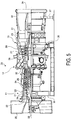
- FIG. 5 is a schematic configuration diagram illustrating a gas turbine according to the present embodiment.
- FIG. 6 is a schematic diagram illustrating main parts of a turbine according to the present embodiment.
- a gas turbine 10 is configured from a compressor 11, combustors 12, and a turbine 13.
- the gas turbine 10 is coaxially coupled to a generator not illustrated in the drawings, and is capable of generating power.
- the compressor 11 includes an air inlet port 20 for taking in air, an inlet guide vane (IGV) 22 disposed inside a compressor casing 21, a plurality of stator blades 23 and rotor blades 24 alternately disposed in the forward/backward direction (the axial direction of a rotor 32 described below) within the compressor casing 21, and an air bleed chamber 25 disposed on the outside of the compressor casing 21.
- the combustor 12 supplies fuel to compressed air compressed by the compressor 11, and ignites the mixture to allow for combustion.
- the turbine 13 includes a plurality of stator blades 27 and rotor blades 28 alternately disposed in the forward/backward direction (the axial direction of the rotor 32 described below) within a turbine casing 26.
- An exhaust chamber 30 is disposed downstream of the turbine casing 26 with an exhaust housing 29 disposed therebetween, and the exhaust chamber 30 includes an exhaust diffuser 31 connected to the turbine 13.
- the rotor (rotating shaft) 32 is positioned so as to pass through the centers of the compressor 11, the combustor 12, the turbine 13, and the exhaust chamber 30.
- the end of the rotor 32 closer to the compressor 11 is rotatably supported by a bearing portion 33, and the end of the rotor 32 closer to the exhaust chamber 30 is rotatably supported by a bearing portion 34.
- a plurality of discs on which the rotor blades 24 are mounted are anchored in layers to the rotor 32 in the compressor 11, a plurality of discs on which the rotor blades 28 are mounted are anchored in layers thereto in the turbine 13, and the end of the rotor 32 closer to the compressor 11 is connected to a drive shaft of a power generator not illustrated in the drawings.
- the compressor casing 21 of the compressor 11 is supported by a leg 35
- the turbine casing 26 of the turbine 13 is supported by a leg 36
- the exhaust chamber 30 is supported by a leg 37.
- air taken in through the air inlet port 20 of the compressor 11 passes through the inlet guide vane 22 and the plurality of stator blades 23 and rotor blades 24 and is compressed, and the air is converted to high-temperature, high-pressure compressed air.
- a predetermined fuel is supplied into the compressed air in the combustors 12 and combusted.
- High-temperature, high-pressure combustion gas which is the working fluid produced by the combustors 12, passes through the plurality of stator blades 27 and rotor blades 28 making up the turbine 13, thereby driving the rotation of the rotor 32 and, in turn, driving the power generator connected to the rotor 32.
- the combustion gas that has driven the turbine 13 is released to the atmosphere as exhaust gas.
- the turbine casing 26 with a cylindrical shape is provided with a combustion gas passage 40 with a ring shape through which combustion gas G flows.
- the plurality of stator blades 27 and rotor blades 28 are disposed in the combustion gas passage 40 at predetermined intervals in a circumferential direction, and are disposed alternately in the flow direction of the combustion gas G.
- an outer shroud 41 is fixed to a first end (the outside in the radial direction) of the stator blade 27, and an inner shroud 42 is fixed to a second end (the inside in the radial direction) of the stator blade 27.
- the outer shroud 41 is supported by the turbine casing 26.
- a platform 43 is fixed to a base end portion (the inside in the radial direction) of the rotor blade 28.
- the platform 43 is fixed to the rotor 32 via the disc, and the tip (the outside in the radial direction) extends to close to the inner wall surface of the turbine casing 26.
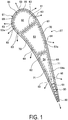
- FIG. 1 is a cross-sectional view illustrating a turbine stator blade according to the present embodiment
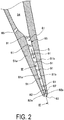
- FIG. 2 is a cross-sectional view of the rear end portion of a turbine blade
- FIG. 3 is a cross-sectional view illustrating a cooling passage of the turbine blade, taken along the line III-III in FIG. 2
- FIG. 4 is a cross-sectional view illustrating an outlet of the cooling passage in the turbine blade.
- the stator blade 27 includes a blade body 51, cavities 52, 53, 54, and a cooling passage 55, as illustrated in FIG. 1 .
- the blade body 51 has a hollow shape, and has a curved cross-sectional shape at the front end portion thereof that is on the upstream side (the top side in FIG. 1 ) in a flow direction of combustion gas, and has a tapered cross-sectional shape at the rear end portion thereof that is on the downstream side (the bottom side in FIG. 1 ) in the flow direction of the combustion gas.
- the interior of the blade body 51 is partitioned into the three cavities 52, 53, 54 by two partition walls 61, 62.
- a first cavity 52 is disposed at the front end portion side of the blade body 51
- a third cavity 54 is disposed at the rear end portion side of the blade body 51
- a second cavity 53 is disposed between the first cavity 52 and the third cavity 54.
- a plurality of cooling holes 63, 64, 65 that pass from the interior to the exterior of the blade body 51 are formed at predetermined locations corresponding to the cavities 52, 53, 52 respectively.
- Partition plates 66, 67, 68 are disposed on the inside of the blade body 51 corresponding to the cavities 52, 53, 54.
- the partition plates 66, 67, 68 have a tubular shape, and each end portion in a longitudinal direction is fixed to the blade body 51 or the shrouds 41, 42.
- Each of the partition plates 66, 67, 68 is disposed with a predetermined gap from the inner wall surface of the blade body 51, so that cooling spaces 52a, 53a, 54a are partitioned around the peripheries of the cavities 52, 53, 54.
- a plurality of through holes 69, 70, 71 are formed in the partition plates 66, 67, 68, so that the cooling spaces 52a, 53a, 54a communicate with the cavities 52, 53, 54 via the through holes 69, 70, 71.
- the cooling passage 55 opens from the third cavity 54 to the rear end portion of the blade body 51.
- the cooling passage 55 includes a first passage 81 and a second passage 82.
- the first passage 81 is provided on the third cavity 54 side, and a width of the first passage 81 becomes narrower from the third cavity 54 side toward the rear end portion of the blade body 51.
- the second passage 82 is provided on the rear end portion side of the blade body 51, and a width of the second passage 82 is constant from the third cavity 54 side toward the rear end portion of the blade body 51.
- a base end portion of the first passage 81 communicates with the third cavity 54, a tip portion of the first passage 81 extends toward the rear end portion of the blade body 51, and the width of the first passage 81 is configured to become narrower.
- the first passage 81 is a passage partitioned by a pressure-side wall portion 51a and a suction-side wall portion 51b forming the blade body 51, and is formed by opposing wall surfaces 81a, 81b. The width between the wall surfaces 81a, 81b becomes narrower toward the downstream side in the flow direction of cooling air S.
- a plurality of cooling pins 91 are provided at predetermined intervals in the first passage 81, to provide a pin fin cooling structure.
- Each of the cooling pins 91 is fixed so as to connect the wall surfaces 81a, 81b of the wall portions 51a, 51b of the blade body 51, and the cooling pins 91 are arranged so as to intersect with the flow direction of the cooling air S flowing through the first passage 81.
- the cooling pins 91 are disposed to form a staggered lattice in the first passage 81.
- the second passage 82 is provided with a flow rate adjustment mechanism, and the flow rate adjustment mechanism is configured by providing a plurality of columns at predetermined intervals along the longitudinal direction in the second passage 82.
- a base end portion of the second passage 82 communicates with the first passage 81
- a tip portion of the second passage 82 extends toward the rear end portion of the blade body 51
- the width of the second passage 82 is configured to be constant.
- the second passage 82 is a passage partitioned by the pressure-side wall portion 51a and the suction-side wall portion 51b forming the blade body 51, and is formed by opposing wall surfaces 82a, 82b.
- the wall surfaces 82a, 82b are parallel in the flow direction of the cooling air S, and the width therebetween is constant.
- the second passage 82 has a nozzle cooling structure that is formed by providing a plurality of pedestals 92 having a column shape at predetermined intervals along a longitudinal direction of the blade body 51 (the horizontal direction in FIG. 3 ). Each of the pedestals 92 is fixed so as to connect the wall surfaces 82a, 82b of the wall portions 51a, 51b of the blade body 51, and the pedestals 92 are arranged so as to intersect with the flow direction of the cooling air S flowing through the second passage 82.
- each of the pedestals 92 facing the adjacent pedestals 92 are flat surfaces along the flow direction of the cooling air S.
- the side surface of each of the pedestals 92 on the upstream side in the flow direction of the cooling air S has a semicircular shape that is convex toward the upstream side, and the side surface thereof on the downstream side in the flow direction of the cooling air S is a flat surface that is orthogonal to the flow direction of the cooling air S.
- side portions of each of the pedestals 92 are smoothly connected to the wall surfaces 82a, 82b in a circular arc shape so that there is no step.
- the cooling passage 55 includes a third passage 83.
- a base end portion of the third passage 83 communicates with the second passage 82, a tip portion of the third passage 83 is open at the rear end portion of the blade body 51, and the width of the third passage 83 is configured to be constant from the third cavity 54 side toward the rear end portion of the blade body 51.
- the third passage 83 is a passage partitioned by the pressure-side wall portion 51a and the suction-side wall portion 51b forming the blade body 51, and is formed by opposing wall surfaces 83a, 83b.
- the wall surfaces 83a, 83b are parallel in the flow direction of the cooling air S, and the width therebetween is constant.
- the first passage 81 is a passage of which the width becomes narrower from the third cavity 54 side toward the rear end portion of the blade body 51, and is provided in a region A.
- the second passage 82 is a passage of which the width is constant from the first passage 81 toward the rear end portion of the blade body 51, and is provided in a region B.
- the wall surfaces 81a, 81b of the first passage 81 are curved along the flow direction of the cooling air S, and the first passage 81 (wall surfaces 81a, 81b) and the second passage 82 (wall surfaces 82a, 82b) are connected without a step.
- the boundary between the first passage 81 (region A) and the second passage 82 (region B) is the point of contact between the wall surfaces 81a, 81b and the side surfaces of the pedestals 92 having the circular arc shape.
- the third passage 83 is a passage of which the width is constant from the second passage 82 toward the rear end portion of the blade body 51, and is provided in a region C.
- the wall surfaces 82a, 82b of the second passage 82 and the wall surfaces 83a, 83b of the third passage 83 are flat surfaces that are parallel along the flow direction of the cooling air S, and the second passage 82 (wall surfaces 82a, 82b) and the third passage 83 (wall surfaces 83a, 83b) are connected without a step.
- the boundary between the second passage 82 (region B) and the third passage 83 (region C) is the point of contact between the wall surfaces 83a, 83b and the side surfaces of the pedestals 92 having the circular arc shape.
- the stator blade 27 configured in this way is manufactured as a casting by a casting process, and a finishing treatment is performed on the outer surface by machining.
- an intermediate product having the blade body 51, the cavities 52, 53, 54, and the cooling passage 55 is manufactured using a mold and a core that are not illustrated in the drawings, and cutting is carried out on the rear end portion of the blade body 51 of the intermediate product produced. More specifically, a portion to be removed 100 is removed by a cutting process from the rear end portion of the blade body 51 in the intermediate product produced, as illustrated in FIG. 4 . As a result of this operation, a total length of the stator blade 27 is finished to the prescribed length.
- the width of the third passage 83 in the cooling passage 55 is constant in the flow direction of the cooling air S. Therefore, the thickness of the core for producing the cooling passage 55 does not become smaller, and, even in a case where there is variation in the length removed of the portion to be removed 100, there is no variation in the width of the third passage 83.
- cooling air (cooling medium) from a cooling passage that is not illustrated in the drawings is supplied to the stator blade 27 from the outer shroud 41
- the cooling air is introduced into each of the cavities 52, 53, 54 on the inside of the respective partition plates 66, 67, 68.
- the cooling air inside the cavities 52, 53, 54 next is injected through the large number of through holes 69, 70, 71 formed in the partition plates 66, 67, 68 into the cooling spaces 52a, 53a, 54a, where the cooling air flows along the inner wall surfaces of the blade body 51 and thereby performs impingement cooling thereon.
- the cooling air in the cooling spaces 52a, 53a, 54a is discharged through the large number of cooling holes 63, 64, 65 to the outside (the combustion gas passage 40).
- the cooling air flows along the outer wall surface of the blade body 51, thereby cooling the outer wall surface.
- a portion of the cooling air in the cooling space 54a cools the rear end portion of the blade body 51 by passing through the cooling passage 55 and being discharged from the rear end portion.
- the cooling air from the cooling space 54a flows through the first passage 81 that has a tapered shape, the flow rate of the cooling air is adjusted, and the cooling efficiency is increased as the cooling air flows in a curved manner while contacting the plurality of cooling pins 91.
- the turbine blade according to the present embodiment includes: the blade body 51 having a hollow shape; the cavities 52, 53, 54 provided in the interior of the blade body 51; and the cooling passage 55 that opens from the cavities 52, 53, 54 to the rear end portion of the blade body 51.
- the first passage 81 provided on the third cavity 54 side and having a width that becomes narrower from the third cavity 54 side toward the rear end portion of the blade body 51, and the second passage 82 provided on the rear end portion side of the blade body 51 and having a width that is constant from the third cavity 54 side toward the rear end portion of the blade body 51 are provided as the cooling passage 55.
- the flow rate of cooling air discharged to the outside from the cooling passage 55 can be appropriately adjusted, and by providing the second passage 82 in which the width is constant, continuously from the first passage 81, the passage resistance can be reduced and the cooling air flow rate can be reduced.
- the resistance can be reduced in the cooling passage 55 at the rear end portion of the blade body 51 and the cooling performance of the stator blade 27 can be improved, and also the increase in manufacturing cost can be minimized.
- the plurality of cooling pins 91 are provided in the first passage 81 at predetermined intervals, and the plurality of pedestals 92 are provided in the second passage 82 along the longitudinal direction of the blade body 51, at predetermined intervals. Therefore, by providing the plurality of cooling pins 91 in the first passage 82 and the plurality of pedestals 92 in the second passage 82, the cooling efficiency of the blade body 51 can be improved by the plurality of cooling pins 91, and the flow of the cooling air can be regulated by the plurality of pedestals 92 so as to be appropriately discharged.
- the flow rate of the cooling air flowing through the cooling passage 55 is reduced and the rear end portion of the blade body 51 can be cooled with high efficiency.
- the third passage 83 is provided as the cooling passage 55.
- the third passage 83 has the first end portion communicating with the second passage 82 and the second end portion being open at the rear end portion of the blade body 51, and has a constant width from the third cavity 54 side toward the rear end portion of the blade body 51. Therefore, by providing the third passage 83 having a constant width and communicating with the second passage 82 so as to open at the rear end portion, the cooling air that has passed through the second passage 82 can be appropriately discharged without pressure loss.
- the plurality of cooling holes 63, 64, 65 that provide communication between the cavities 52, 53, 54 and the exterior are provided in the blade body 51. Therefore, the cooling air discharged to the exterior through the plurality of cooling holes 63, 64, 65 from the cavities 52, 53, 54 flows along the outer wall surfaces of the blade body 51, and cools the blade body 51 with high efficiency.
- the partition plates 66, 67, 68 having the plurality of through holes 69, 70, 71 are provided in the cavities 52, 53, 54 with a predetermined gap from the inner wall surfaces of the blade body 51. Therefore, the cooling air from the cavities 52, 53, 54 that has passed through the through holes 69, 70, 71 of the partition plates 66, 67, 68 flows along the inner wall surfaces of the blade body 51, and cools the blade body 51 with high efficiency.
- the gas turbine according to the present embodiment includes the compressor 11 that compresses air, the combustors 12 that mix the compressed air compressed by the compressor 11 with fuel and cause combustion, and the turbine 13 that obtains the rotational power by the combustion gas generated by the combustors 12, and the stator blade 27 is used in the turbine 13. Therefore, the resistance can be reduced in the cooling passage 55 at the rear end portion of the blade body 51, the cooling performance of the stator blade 27 can be improved, and also the increase in manufacturing cost can be minimized.
- the intermediate product of a turbine blade according to the present embodiment includes, as the cooling passage 55 provided in the blade body 51: the first passage 81 whose width becomes narrower; the second passage 82 having a constant width; the plurality of pedestals 92 of the second passage 82; and the third passage 83 that communicates with the second passage 82 and that is open at the rear end portion of the blade body 51. Therefore, the stator blade 27 of the turbine 13 can be easily manufactured by just finishing the intermediate product.
- the method of manufacturing a turbine blade according to the present embodiment includes: producing the intermediate product of the stator blade 27 by casting; and cutting the rear end portion of the blade body 51 in the cast intermediate product. Therefore, the width of the third passage does not vary even if the rear end portion of the blade body 51 in the cast intermediate product is cut, and high cooling performance can be maintained by the second passage 82.
- the boundary between the first passage 81 (region A) and the second passage 82 (region B) in the present embodiment is the point of contact between the wall surfaces 81a, 81b and the side surfaces of the pedestals 92 having the circular arc shape, but the boundary may be on the third cavity 54 side of the point of contact.
- the second passage 82 may extend to the upstream side in the flow direction of the cooling air S.
- the third passage 83 having a constant width is provided as the cooling passage 55, but the width of the third passage may increase from the third cavity 54 side toward the rear end portion of the blade body 51.
- an outlet (nozzle) of the cooling air S is formed by disposing the plurality of pedestals 92 in the second passage 82 of the blade body 51, but a plurality of outlet holes may be disposed in parallel in the rear end portion of the blade body 51, and the first passage 81 and the second passage 82 may be formed on the inside of the outlet holes.
- the turbine blade according to the present invention is applied to the stator blades 27 of the turbine 13, but it may also be applied to the rotor blades 28.
Landscapes
- Engineering & Computer Science (AREA)
- Mechanical Engineering (AREA)
- General Engineering & Computer Science (AREA)
- Chemical & Material Sciences (AREA)
- Combustion & Propulsion (AREA)
- Turbine Rotor Nozzle Sealing (AREA)
Abstract
Description
- The present invention relates to a turbine blade used as a stator blade or a rotor blade in a gas turbine, a gas turbine in which this turbine blade is applied, an intermediate product for manufacturing the turbine blade, and a method of manufacturing a turbine blade for manufacturing the turbine blade.
- A typical gas turbine is configured from a compressor, a combustor, and a turbine. Air taken in through an air inlet is compressed by the compressor to produce high-temperature, high-pressure compressed air, to which fuel is supplied and the two are combusted in the combustor to obtain high-temperature, high-pressure combustion gas (operating fluid), which is used to drive the turbine, thereby driving a power generator coupled to the turbine.
- In a turbine configured in this way, for example, a stator blade is supported by an outer shroud at a first end portion in the longitudinal direction of the blade body, and is supported by an inner shroud at a second end portion. Cooling air introduced into the blade body from the outer shroud flows along the inner wall surfaces of the blade body to cool the inner wall surfaces of the blade body, and then is discharged to the outside from a cooling hole formed in the blade body and flows along the outer wall surfaces of the blade body to cool the outer wall surfaces of the blade body. Also, the cooling air introduced into the blade body flows along a cooling passage formed in the rear end portion of the blade body and is discharged to the outside, thereby cooling the rear end portion of the blade body.
- An example of a gas turbine in which such a stator blade cooling structure is applied is disclosed in Patent Document 1 described below. In the turbine stator blade disclosed in Patent Document 1, a plurality of cooling pins are disposed in a cooling passage formed in the rear end portion of the blade body, and a plurality of pedestals are arranged at the outlet of the cooling passage to form a nozzle shape. Also, the cooling passage has a tapered shape in which the width becomes narrower toward the outlet.
- Patent Document 1:
JP 2009-287511A - It is desirable to improve the cooling performance of the blade body of the stator blade, so it is desirable that the width of the cooling passage of the rear end portion is made narrower, and the coefficient of drag (Cd value) is made smaller. Therefore, in the related art, the cooling passage of the blade body has a tapered shape that becomes narrower toward the outlet. However, because the cooling passage of the blade body has a tapered shape, highly accurate processing technology is required in order to properly set the width of the opening of the tip of the outlet, and this has the issue that the processing cost is increased.
- The present invention resolves the above-mentioned issue, and it is an object of the present invention to provide a turbine blade, a gas turbine, an intermediate product of a turbine blade, and a method of manufacturing a turbine blade that reduce the resistance of the cooling passage of the rear end portion of the blade and improve the cooling performance of the blade, as well as minimize the increase in manufacturing cost.
- A turbine blade according to the present invention to achieve the above object includes: a blade body having a hollow shape; a cavity provided in the interior of the blade body; and a cooling passage that is open from the cavity to a rear end portion of the blade body. The cooling passage includes a first passage provided on the cavity side and having a width that becomes narrower from the cavity side toward the rear end portion of the blade body, and a second passage provided on the rear end portion side of the blade body and having a width that is constant from the cavity side toward the rear end portion of the blade body.
- Therefore, by providing the first passage in which the width becomes narrower as the cooling passage, the flow rate of cooling air discharged to the outside from the cooling passage can be appropriately adjusted, and by providing the second passage in which the width is constant, continuously from the first passage, the passage resistance can be reduced and the cooling air flow rate can be reduced. As a result, the resistance can be reduced in the cooling passage at the rear end portion of the blade and the cooling performance of the blade can be improved, and also the increase in manufacturing cost can be minimized.
- In the turbine blade according to the present invention, a flow rate adjustment mechanism is provided in the second passage.
- Therefore, by providing the flow rate adjustment mechanism in the second passage, the flow of the cooling air can be regulated by the flow rate adjustment mechanism so as to be appropriately discharged.
- In the turbine blade according to the present invention, the flow rate adjustment mechanism has a plurality of columns provided at predetermined intervals in the second passage of the blade body along a longitudinal direction.
- Therefore, the flow rate adjustment mechanism is configured by providing the plurality of columns at predetermined intervals along the longitudinal direction of the second passage, and the structure can be thus simplified.
- In the turbine blade according to the present invention, the cooling passage includes a third passage that communicates with the second passage at a first end portion thereof and is open at the rear end portion of the blade body at a second end portion thereof, and that has a constant width from the cavity side toward the rear end portion of the blade body.
- Therefore, by providing the third passage having a constant width and communicating with the second passage so as to open at the rear end portion, the cooling air that has passed through the second passage can be appropriately discharged without pressure loss.
- In the turbine blade according to the present invention, a plurality of cooling holes that provide communication between the cavity and the exterior are provided in the blade body.
- Therefore, the cooling air discharged to the exterior through the plurality of cooling holes from the cavity flows along the outer wall surfaces of the blade body, and cools the blade body with high efficiency.
- In the turbine blade according to the present invention, a partition plate having a plurality of through holes is provided in the cavity with a predetermined gap from an inner wall surface of the blade body.
- Therefore, the cooling air from the cavity that has passed through the through holes of the partition plate flows along the inner wall surfaces of the blade body, and cools the blade body with high efficiency.
- A gas turbine according to the present invention includes a compressor that compresses air, a combustor that mixes compressed air compressed by the compressor with fuel and causes combustion, and a turbine that obtains rotational power by combustion gas generated by the combustor, and the above-described turbine stator blade is used as a stator blade of the turbine.
- Therefore, the resistance can be reduced in the cooling passage at the rear end portion of the blade and the cooling performance of the blade can be increased, and also the increase in manufacturing cost can be minimized.
- An intermediate product of a turbine blade according to the present invention includes: a blade body having a hollow shape; a cavity provided in the interior of the blade body; and a cooling passage that is open from the cavity to a rear end portion of the blade body. The cooling passage includes a first passage provided on the cavity side and having a width that becomes narrower from the cavity side toward the rear end portion of the blade body; a second passage provided on the rear end portion side of the blade body and having a width that is constant from the cavity side toward the rear end portion of the blade body; a flow rate adjustment mechanism provided in the second passage; and a third passage that communicates with the second passage at a first end portion of the third passage and that is open at the rear end portion of the blade body at a second end portion of the third passage.
- Therefore, by providing the intermediate product having the second passage with a constant width as the cooling passage, the stator blade of the turbine can be easily manufactured by just finishing the intermediate product.
- In the intermediate product of a turbine blade according to the present invention, the flow rate adjustment mechanism has a plurality of columns provided at predetermined intervals in the second passage of the blade body along a longitudinal direction.
- Therefore, the flow rate adjustment mechanism is configured by providing the plurality of columns at predetermined intervals along the longitudinal direction of the second passage, and thus the structure can be simplified.
- A method of manufacturing a turbine blade according to the present invention includes producing the intermediate product of a turbine blade by casting; and cutting the rear end portion of the blade body in the cast intermediate product.
- Therefore, the width of the third passage does not vary even in a case where the rear end portion of the blade body in the cast intermediate product is cut, and high cooling performance can be maintained by the second passage.
- According to the turbine blade, gas turbine, intermediate product of a turbine blade, and method of manufacturing a turbine blade of the present invention, the first passage having a decreasing width and the second passage that continues from the first passage and has a constant width are provided as the cooling passage. Therefore, the resistance can be reduced in the cooling passage at the rear end portion of the blade, the cooling performance of the blade can be improved, and also the increase in manufacturing cost can be minimized.
-
-
FIG. 1 is a cross-sectional view illustrating a turbine stator blade according to the present embodiment. -
FIG. 2 is a cross-sectional view illustrating a rear end portion of a turbine blade. -
FIG. 3 is a cross-sectional view illustrating a cooling passage of the turbine blade, taken along the line III-III inFIG. 2 . -
FIG. 4 is a cross-sectional view illustrating an outlet of the cooling passage in the turbine blade. -
FIG. 5 is a schematic configuration diagram illustrating a gas turbine according to the present embodiment. -
FIG. 6 is a schematic diagram illustrating main parts of a turbine according to the present embodiment. - Preferred embodiments of a turbine blade, gas turbine, intermediate product of a turbine blade, and method of manufacturing a turbine blade according to the present invention are described in detail below with reference to the attached drawings. Note that the present invention is not limited by these embodiments, and, when there are a plurality of embodiments, includes combinations of those various embodiments.
-
FIG. 5 is a schematic configuration diagram illustrating a gas turbine according to the present embodiment.FIG. 6 is a schematic diagram illustrating main parts of a turbine according to the present embodiment. - As illustrated in
FIG. 5 , in the present embodiment, agas turbine 10 is configured from acompressor 11,combustors 12, and aturbine 13. Thegas turbine 10 is coaxially coupled to a generator not illustrated in the drawings, and is capable of generating power. - The
compressor 11 includes anair inlet port 20 for taking in air, an inlet guide vane (IGV) 22 disposed inside acompressor casing 21, a plurality ofstator blades 23 androtor blades 24 alternately disposed in the forward/backward direction (the axial direction of arotor 32 described below) within thecompressor casing 21, and an air bleedchamber 25 disposed on the outside of thecompressor casing 21. Thecombustor 12 supplies fuel to compressed air compressed by thecompressor 11, and ignites the mixture to allow for combustion. Theturbine 13 includes a plurality ofstator blades 27 androtor blades 28 alternately disposed in the forward/backward direction (the axial direction of therotor 32 described below) within aturbine casing 26. Anexhaust chamber 30 is disposed downstream of theturbine casing 26 with anexhaust housing 29 disposed therebetween, and theexhaust chamber 30 includes anexhaust diffuser 31 connected to theturbine 13. - The rotor (rotating shaft) 32 is positioned so as to pass through the centers of the
compressor 11, thecombustor 12, theturbine 13, and theexhaust chamber 30. The end of therotor 32 closer to thecompressor 11 is rotatably supported by abearing portion 33, and the end of therotor 32 closer to theexhaust chamber 30 is rotatably supported by abearing portion 34. A plurality of discs on which therotor blades 24 are mounted are anchored in layers to therotor 32 in thecompressor 11, a plurality of discs on which therotor blades 28 are mounted are anchored in layers thereto in theturbine 13, and the end of therotor 32 closer to thecompressor 11 is connected to a drive shaft of a power generator not illustrated in the drawings. - In the
gas turbine 10, thecompressor casing 21 of thecompressor 11 is supported by aleg 35, theturbine casing 26 of theturbine 13 is supported by aleg 36, and theexhaust chamber 30 is supported by aleg 37. - Accordingly, air taken in through the
air inlet port 20 of thecompressor 11 passes through theinlet guide vane 22 and the plurality ofstator blades 23 androtor blades 24 and is compressed, and the air is converted to high-temperature, high-pressure compressed air. A predetermined fuel is supplied into the compressed air in thecombustors 12 and combusted. High-temperature, high-pressure combustion gas, which is the working fluid produced by thecombustors 12, passes through the plurality ofstator blades 27 androtor blades 28 making up theturbine 13, thereby driving the rotation of therotor 32 and, in turn, driving the power generator connected to therotor 32. The combustion gas that has driven theturbine 13 is released to the atmosphere as exhaust gas. - As illustrated in
FIG. 6 , in theturbine 13 described above, theturbine casing 26 with a cylindrical shape is provided with acombustion gas passage 40 with a ring shape through which combustion gas G flows. The plurality ofstator blades 27 androtor blades 28 are disposed in thecombustion gas passage 40 at predetermined intervals in a circumferential direction, and are disposed alternately in the flow direction of the combustion gas G. In a longitudinal direction of the stator blade 27 (radial direction of the rotor 32), anouter shroud 41 is fixed to a first end (the outside in the radial direction) of thestator blade 27, and aninner shroud 42 is fixed to a second end (the inside in the radial direction) of thestator blade 27. Theouter shroud 41 is supported by theturbine casing 26. In a longitudinal direction of the rotor blade 28 (radial direction of the rotor 32), aplatform 43 is fixed to a base end portion (the inside in the radial direction) of therotor blade 28. Theplatform 43 is fixed to therotor 32 via the disc, and the tip (the outside in the radial direction) extends to close to the inner wall surface of theturbine casing 26. - The following is a detailed description of the
stator blade 27 that constitutes the turbine blade according to the present invention.FIG. 1 is a cross-sectional view illustrating a turbine stator blade according to the present embodiment;FIG. 2 is a cross-sectional view of the rear end portion of a turbine blade;FIG. 3 is a cross-sectional view illustrating a cooling passage of the turbine blade, taken along the line III-III inFIG. 2 ; andFIG. 4 is a cross-sectional view illustrating an outlet of the cooling passage in the turbine blade. - In the present embodiment, the
stator blade 27 includes ablade body 51,cavities cooling passage 55, as illustrated inFIG. 1 . - The
blade body 51 has a hollow shape, and has a curved cross-sectional shape at the front end portion thereof that is on the upstream side (the top side inFIG. 1 ) in a flow direction of combustion gas, and has a tapered cross-sectional shape at the rear end portion thereof that is on the downstream side (the bottom side inFIG. 1 ) in the flow direction of the combustion gas. The interior of theblade body 51 is partitioned into the threecavities partition walls first cavity 52 is disposed at the front end portion side of theblade body 51, athird cavity 54 is disposed at the rear end portion side of theblade body 51, and asecond cavity 53 is disposed between thefirst cavity 52 and thethird cavity 54. Also, a plurality of cooling holes 63, 64, 65 that pass from the interior to the exterior of theblade body 51 are formed at predetermined locations corresponding to thecavities -
Partition plates blade body 51 corresponding to thecavities partition plates blade body 51 or theshrouds partition plates blade body 51, so that coolingspaces cavities holes partition plates spaces cavities holes - The
cooling passage 55 opens from thethird cavity 54 to the rear end portion of theblade body 51. Thecooling passage 55 includes afirst passage 81 and asecond passage 82. Thefirst passage 81 is provided on thethird cavity 54 side, and a width of thefirst passage 81 becomes narrower from thethird cavity 54 side toward the rear end portion of theblade body 51. Thesecond passage 82 is provided on the rear end portion side of theblade body 51, and a width of thesecond passage 82 is constant from thethird cavity 54 side toward the rear end portion of theblade body 51. - As illustrated in
FIG. 2 to FIG. 4 , a base end portion of thefirst passage 81 communicates with thethird cavity 54, a tip portion of thefirst passage 81 extends toward the rear end portion of theblade body 51, and the width of thefirst passage 81 is configured to become narrower. In other words, thefirst passage 81 is a passage partitioned by a pressure-side wall portion 51a and a suction-side wall portion 51b forming theblade body 51, and is formed by opposingwall surfaces first passage 81, to provide a pin fin cooling structure. Each of the cooling pins 91 is fixed so as to connect the wall surfaces 81a, 81b of thewall portions blade body 51, and the cooling pins 91 are arranged so as to intersect with the flow direction of the cooling air S flowing through thefirst passage 81. Also, the cooling pins 91 are disposed to form a staggered lattice in thefirst passage 81. - The
second passage 82 is provided with a flow rate adjustment mechanism, and the flow rate adjustment mechanism is configured by providing a plurality of columns at predetermined intervals along the longitudinal direction in thesecond passage 82. In other words, a base end portion of thesecond passage 82 communicates with thefirst passage 81, a tip portion of thesecond passage 82 extends toward the rear end portion of theblade body 51, and the width of thesecond passage 82 is configured to be constant. In other words, thesecond passage 82 is a passage partitioned by the pressure-side wall portion 51a and the suction-side wall portion 51b forming theblade body 51, and is formed by opposingwall surfaces second passage 82 has a nozzle cooling structure that is formed by providing a plurality ofpedestals 92 having a column shape at predetermined intervals along a longitudinal direction of the blade body 51 (the horizontal direction inFIG. 3 ). Each of thepedestals 92 is fixed so as to connect the wall surfaces 82a, 82b of thewall portions blade body 51, and thepedestals 92 are arranged so as to intersect with the flow direction of the cooling air S flowing through thesecond passage 82. - The side surfaces of each of the
pedestals 92 facing theadjacent pedestals 92 are flat surfaces along the flow direction of the cooling air S. The side surface of each of thepedestals 92 on the upstream side in the flow direction of the cooling air S has a semicircular shape that is convex toward the upstream side, and the side surface thereof on the downstream side in the flow direction of the cooling air S is a flat surface that is orthogonal to the flow direction of the cooling air S. Also, side portions of each of thepedestals 92 are smoothly connected to the wall surfaces 82a, 82b in a circular arc shape so that there is no step. - Also, the
cooling passage 55 includes athird passage 83. A base end portion of thethird passage 83 communicates with thesecond passage 82, a tip portion of thethird passage 83 is open at the rear end portion of theblade body 51, and the width of thethird passage 83 is configured to be constant from thethird cavity 54 side toward the rear end portion of theblade body 51. In other words, thethird passage 83 is a passage partitioned by the pressure-side wall portion 51a and the suction-side wall portion 51b forming theblade body 51, and is formed by opposingwall surfaces - In other words, the
first passage 81 is a passage of which the width becomes narrower from thethird cavity 54 side toward the rear end portion of theblade body 51, and is provided in a region A. Thesecond passage 82 is a passage of which the width is constant from thefirst passage 81 toward the rear end portion of theblade body 51, and is provided in a region B. Here, the wall surfaces 81a, 81b of thefirst passage 81 are curved along the flow direction of the cooling air S, and the first passage 81 (wall surfaces 81a, 81b) and the second passage 82 (wall surfaces 82a, 82b) are connected without a step. The boundary between the first passage 81 (region A) and the second passage 82 (region B) is the point of contact between the wall surfaces 81a, 81b and the side surfaces of thepedestals 92 having the circular arc shape. Thethird passage 83 is a passage of which the width is constant from thesecond passage 82 toward the rear end portion of theblade body 51, and is provided in a region C. Here, the wall surfaces 82a, 82b of thesecond passage 82 and the wall surfaces 83a, 83b of thethird passage 83 are flat surfaces that are parallel along the flow direction of the cooling air S, and the second passage 82 (wall surfaces 82a, 82b) and the third passage 83 (wall surfaces 83a, 83b) are connected without a step. The boundary between the second passage 82 (region B) and the third passage 83 (region C) is the point of contact between the wall surfaces 83a, 83b and the side surfaces of thepedestals 92 having the circular arc shape. - The
stator blade 27 configured in this way is manufactured as a casting by a casting process, and a finishing treatment is performed on the outer surface by machining. Specifically, an intermediate product having theblade body 51, thecavities cooling passage 55 is manufactured using a mold and a core that are not illustrated in the drawings, and cutting is carried out on the rear end portion of theblade body 51 of the intermediate product produced. More specifically, a portion to be removed 100 is removed by a cutting process from the rear end portion of theblade body 51 in the intermediate product produced, as illustrated inFIG. 4 . As a result of this operation, a total length of thestator blade 27 is finished to the prescribed length. In this case, the width of thethird passage 83 in thecooling passage 55 is constant in the flow direction of the cooling air S. Therefore, the thickness of the core for producing thecooling passage 55 does not become smaller, and, even in a case where there is variation in the length removed of the portion to be removed 100, there is no variation in the width of thethird passage 83. - Next, the operation of the
stator blade 27 of the present embodiment will be described. - As illustrated in
FIG. 1 , when cooling air (cooling medium) from a cooling passage that is not illustrated in the drawings is supplied to thestator blade 27 from theouter shroud 41, first, the cooling air is introduced into each of thecavities respective partition plates cavities holes partition plates spaces blade body 51 and thereby performs impingement cooling thereon. - Thereafter, the cooling air in the
cooling spaces blade body 51, thereby cooling the outer wall surface. Also, a portion of the cooling air in thecooling space 54a cools the rear end portion of theblade body 51 by passing through thecooling passage 55 and being discharged from the rear end portion. At this time, when the cooling air from thecooling space 54a flows through thefirst passage 81 that has a tapered shape, the flow rate of the cooling air is adjusted, and the cooling efficiency is increased as the cooling air flows in a curved manner while contacting the plurality of cooling pins 91. Then, when the cooling air that has passed through thefirst passage 81 flows through thesecond passage 82 and thethird passage 83 in which the width is constant, the cooling air passes between each of thepedestals 92, so that the coefficient of drag (Cd value) is reduced and the rear end portion of theblade body 51 is cooled with a low air flow rate. - In this way, the turbine blade according to the present embodiment includes: the
blade body 51 having a hollow shape; thecavities blade body 51; and thecooling passage 55 that opens from thecavities blade body 51. Thefirst passage 81 provided on thethird cavity 54 side and having a width that becomes narrower from thethird cavity 54 side toward the rear end portion of theblade body 51, and thesecond passage 82 provided on the rear end portion side of theblade body 51 and having a width that is constant from thethird cavity 54 side toward the rear end portion of theblade body 51 are provided as thecooling passage 55. - Therefore, by providing the
first passage 81 in which the width becomes narrower as thecooling passage 55, the flow rate of cooling air discharged to the outside from thecooling passage 55 can be appropriately adjusted, and by providing thesecond passage 82 in which the width is constant, continuously from thefirst passage 81, the passage resistance can be reduced and the cooling air flow rate can be reduced. As a result, the resistance can be reduced in thecooling passage 55 at the rear end portion of theblade body 51 and the cooling performance of thestator blade 27 can be improved, and also the increase in manufacturing cost can be minimized. - In the turbine blade according to the present embodiment, the plurality of cooling pins 91 are provided in the
first passage 81 at predetermined intervals, and the plurality ofpedestals 92 are provided in thesecond passage 82 along the longitudinal direction of theblade body 51, at predetermined intervals. Therefore, by providing the plurality of cooling pins 91 in thefirst passage 82 and the plurality ofpedestals 92 in thesecond passage 82, the cooling efficiency of theblade body 51 can be improved by the plurality of cooling pins 91, and the flow of the cooling air can be regulated by the plurality ofpedestals 92 so as to be appropriately discharged. In other words, by forming the region B, where thepedestals 92 are provided, as thesecond passage 82 with a constant width, the flow rate of the cooling air flowing through thecooling passage 55 is reduced and the rear end portion of theblade body 51 can be cooled with high efficiency. - In the turbine blade according to the present embodiment, the
third passage 83 is provided as thecooling passage 55. Thethird passage 83 has the first end portion communicating with thesecond passage 82 and the second end portion being open at the rear end portion of theblade body 51, and has a constant width from thethird cavity 54 side toward the rear end portion of theblade body 51. Therefore, by providing thethird passage 83 having a constant width and communicating with thesecond passage 82 so as to open at the rear end portion, the cooling air that has passed through thesecond passage 82 can be appropriately discharged without pressure loss. - In the turbine blade according to the present embodiment, the plurality of cooling holes 63, 64, 65 that provide communication between the
cavities blade body 51. Therefore, the cooling air discharged to the exterior through the plurality of cooling holes 63, 64, 65 from thecavities blade body 51, and cools theblade body 51 with high efficiency. - In the turbine blade according to the present embodiment, the
partition plates holes cavities blade body 51. Therefore, the cooling air from thecavities holes partition plates blade body 51, and cools theblade body 51 with high efficiency. - The gas turbine according to the present embodiment includes the
compressor 11 that compresses air, thecombustors 12 that mix the compressed air compressed by thecompressor 11 with fuel and cause combustion, and theturbine 13 that obtains the rotational power by the combustion gas generated by thecombustors 12, and thestator blade 27 is used in theturbine 13. Therefore, the resistance can be reduced in thecooling passage 55 at the rear end portion of theblade body 51, the cooling performance of thestator blade 27 can be improved, and also the increase in manufacturing cost can be minimized. - The intermediate product of a turbine blade according to the present embodiment includes, as the
cooling passage 55 provided in the blade body 51: thefirst passage 81 whose width becomes narrower; thesecond passage 82 having a constant width; the plurality ofpedestals 92 of thesecond passage 82; and thethird passage 83 that communicates with thesecond passage 82 and that is open at the rear end portion of theblade body 51. Therefore, thestator blade 27 of theturbine 13 can be easily manufactured by just finishing the intermediate product. - The method of manufacturing a turbine blade according to the present embodiment includes: producing the intermediate product of the
stator blade 27 by casting; and cutting the rear end portion of theblade body 51 in the cast intermediate product. Therefore, the width of the third passage does not vary even if the rear end portion of theblade body 51 in the cast intermediate product is cut, and high cooling performance can be maintained by thesecond passage 82. - Note that the boundary between the first passage 81 (region A) and the second passage 82 (region B) in the present embodiment is the point of contact between the wall surfaces 81a, 81b and the side surfaces of the
pedestals 92 having the circular arc shape, but the boundary may be on thethird cavity 54 side of the point of contact. In other words, thesecond passage 82 may extend to the upstream side in the flow direction of the cooling air S. - Also, in the embodiment as described above, the
third passage 83 having a constant width is provided as thecooling passage 55, but the width of the third passage may increase from thethird cavity 54 side toward the rear end portion of theblade body 51. - Also, in the embodiment as described above, an outlet (nozzle) of the cooling air S is formed by disposing the plurality of
pedestals 92 in thesecond passage 82 of theblade body 51, but a plurality of outlet holes may be disposed in parallel in the rear end portion of theblade body 51, and thefirst passage 81 and thesecond passage 82 may be formed on the inside of the outlet holes. - Also, in the embodiment as described above, the turbine blade according to the present invention is applied to the
stator blades 27 of theturbine 13, but it may also be applied to therotor blades 28. -
- 10 Gas turbine
- 11 Compressor
- 12 Combustor
- 13 Turbine
- 27 Stator blade
- 28 Rotor blade
- 41 Outer shroud
- 42 Inner shroud
- 51 Blade body
- 52, 53, 54 Cavity
- 52a, 53a, 54a Cooling space
- 55 Cooling passage
- 61, 62 Partition wall
- 63, 64, 65 Cooling hole
- 66, 67, 68 Partition plate
- 69, 70, 71 Through hole
- 81 First passage
- 81a, 81b Wall surface
- 82 Second passage
- 82a, 82b Wall surface
- 83 Third passage
- 83a, 83b Wall surface
- 91 Cooling pin
- 92 Pedestal
- G Combustion gas
- S Cooling air
Claims (10)
- A turbine blade, comprising:a blade body having a hollow shape;a cavity provided in the interior of the blade body; anda cooling passage that is open from the cavity to a rear end portion of the blade body, whereinthe cooling passage includesa first passage provided on the cavity side and having a width that becomes narrower from the cavity side toward the rear end portion of the blade body, anda second passage provided on the rear end portion side of the blade body and having a width that is constant from the cavity side toward the rear end portion of the blade body.
- The turbine blade according to claim 1, wherein a flow rate adjustment mechanism is provided in the second passage.
- The turbine blade according to claim 2, wherein the flow rate adjustment mechanism has a plurality of columns provided at predetermined intervals in the second passage of the blade body along a longitudinal direction.
- The turbine blade according to any one of claims 1 to 3, wherein the cooling passage includes a third passage having a constant width from the cavity side toward the rear end portion of the blade body, a first end portion of the third passage communicating with the second passage and a second end portion of the third passage opening at the rear end portion of the blade body.
- The turbine blade according to any one of claims 1 to 4, wherein a plurality of cooling holes that provide communication between the cavity and the exterior are provided in the blade body.
- The turbine blade according to claim 5, wherein a partition plate having a plurality of through holes is provided in the cavity with a predetermined gap from an inner wall surface of the blade body.
- A gas turbine, comprising:a compressor that compresses air;a combustor that mixes compressed air compressed by the compressor with fuel and causes combustion; anda turbine that obtains rotational power by combustion gas generated by the combustor, whereinthe turbine blade according to any one of claims 1 to 6 is used as a stator blade of the turbine.
- An intermediate product of a turbine blade, comprising:a blade body having a hollow shape;a cavity provided in the interior of the blade body; anda cooling passage that is open from the cavity to a rear end portion of the blade body, whereinthe cooling passage includesa first passage provided on the cavity side and having a width that becomes narrower from the cavity side toward the rear end portion of the blade body,a second passage provided on the rear end portion side of the blade body and having a width that is constant from the cavity side toward the rear end portion of the blade body,a flow rate adjustment mechanism provided in the second passage, anda third passage that communicates with the second passage at a first end portion thereof and that is open at the rear end portion of the blade body at a second end portion thereof.
- The intermediate product of a turbine blade according to claim 8, wherein the flow rate adjustment mechanism has a plurality of columns provided at predetermined intervals in the second passage of the blade body along a longitudinal direction.
- A method of manufacturing a turbine blade, comprising:producing the intermediate product of a turbine blade according to claim 8 or 9 by casting; andcutting a rear end portion of the blade body in the cast intermediate product.
Applications Claiming Priority (2)
| Application Number | Priority Date | Filing Date | Title |
|---|---|---|---|
| JP2015217753A JP6671149B2 (en) | 2015-11-05 | 2015-11-05 | Turbine blade and gas turbine, intermediate product of turbine blade, and method of manufacturing turbine blade |
| PCT/JP2016/082740 WO2017078122A1 (en) | 2015-11-05 | 2016-11-04 | Turbine blade, gas turbine, intermediate product of turbine blade, and method of manufacturing turbine blade |
Publications (3)
| Publication Number | Publication Date |
|---|---|
| EP3372787A1 true EP3372787A1 (en) | 2018-09-12 |
| EP3372787A4 EP3372787A4 (en) | 2018-11-21 |
| EP3372787B1 EP3372787B1 (en) | 2021-02-17 |
Family
ID=58662078
Family Applications (1)
| Application Number | Title | Priority Date | Filing Date |
|---|---|---|---|
| EP16862182.9A Active EP3372787B1 (en) | 2015-11-05 | 2016-11-04 | Turbine blade, gas turbine, and method of manufacturing turbine blade |
Country Status (7)
| Country | Link |
|---|---|
| US (1) | US11384643B2 (en) |
| EP (1) | EP3372787B1 (en) |
| JP (1) | JP6671149B2 (en) |
| KR (1) | KR20180059912A (en) |
| CN (1) | CN108350746B (en) |
| TW (1) | TWI698576B (en) |
| WO (1) | WO2017078122A1 (en) |
Families Citing this family (6)
| Publication number | Priority date | Publication date | Assignee | Title |
|---|---|---|---|---|
| US10309242B2 (en) * | 2016-08-10 | 2019-06-04 | General Electric Company | Ceramic matrix composite component cooling |
| US10718217B2 (en) * | 2017-06-14 | 2020-07-21 | General Electric Company | Engine component with cooling passages |
| KR102494689B1 (en) * | 2018-07-13 | 2023-01-31 | 지멘스 에너지 글로벌 게엠베하 운트 코. 카게 | Airfoils for turbine engines incorporating fins |
| JP6745012B1 (en) * | 2019-10-31 | 2020-08-26 | 三菱日立パワーシステムズ株式会社 | Turbine blade and gas turbine equipped with the same |
| JP2024043164A (en) * | 2022-09-16 | 2024-03-29 | 三菱重工航空エンジン株式会社 | heat exchange bulkhead |
| CN115570105B (en) * | 2022-11-21 | 2023-05-05 | 中国航发四川燃气涡轮研究院 | Manufacturing method of double-wall turbine blade |
Family Cites Families (19)
| Publication number | Priority date | Publication date | Assignee | Title |
|---|---|---|---|---|
| US4297077A (en) * | 1979-07-09 | 1981-10-27 | Westinghouse Electric Corp. | Cooled turbine vane |
| JP3651490B2 (en) * | 1993-12-28 | 2005-05-25 | 株式会社東芝 | Turbine cooling blade |
| JP3241241B2 (en) * | 1995-08-09 | 2001-12-25 | 三菱重工業株式会社 | Hollow gas turbine blades |
| US5931638A (en) * | 1997-08-07 | 1999-08-03 | United Technologies Corporation | Turbomachinery airfoil with optimized heat transfer |
| JP3494879B2 (en) | 1998-03-25 | 2004-02-09 | 株式会社日立製作所 | Gas turbine and gas turbine vane |
| US6234754B1 (en) | 1999-08-09 | 2001-05-22 | United Technologies Corporation | Coolable airfoil structure |
| US6270317B1 (en) * | 1999-12-18 | 2001-08-07 | General Electric Company | Turbine nozzle with sloped film cooling |
| DE19963349A1 (en) * | 1999-12-27 | 2001-06-28 | Abb Alstom Power Ch Ag | Blade for gas turbines with throttle cross section at the rear edge |
| US7014424B2 (en) | 2003-04-08 | 2006-03-21 | United Technologies Corporation | Turbine element |
| US7175386B2 (en) * | 2003-12-17 | 2007-02-13 | United Technologies Corporation | Airfoil with shaped trailing edge pedestals |
| US8070441B1 (en) * | 2007-07-20 | 2011-12-06 | Florida Turbine Technologies, Inc. | Turbine airfoil with trailing edge cooling channels |
| JP5182931B2 (en) | 2008-05-30 | 2013-04-17 | 三菱重工業株式会社 | Turbine blade |
| CH700321A1 (en) | 2009-01-30 | 2010-07-30 | Alstom Technology Ltd | Cooled vane for a gas turbine. |
| RU2543914C2 (en) * | 2010-03-19 | 2015-03-10 | Альстом Текнолоджи Лтд | Gas turbine vane with aerodynamic profile and profiled holes on back edge for cooling agent discharge |
| US9366144B2 (en) * | 2012-03-20 | 2016-06-14 | United Technologies Corporation | Trailing edge cooling |
| US9175569B2 (en) | 2012-03-30 | 2015-11-03 | General Electric Company | Turbine airfoil trailing edge cooling slots |
| US20130302176A1 (en) * | 2012-05-08 | 2013-11-14 | Robert Frederick Bergholz, JR. | Turbine airfoil trailing edge cooling slot |
| WO2015012918A2 (en) * | 2013-06-04 | 2015-01-29 | United Technologies Corporation | Gas turbine engine airfoil trailing edge suction side cooling |
| US20150204237A1 (en) * | 2014-01-17 | 2015-07-23 | General Electric Company | Turbine blade and method for enhancing life of the turbine blade |
-
2015
- 2015-11-05 JP JP2015217753A patent/JP6671149B2/en active Active
-
2016
- 2016-11-02 TW TW105135550A patent/TWI698576B/en active
- 2016-11-04 US US15/771,257 patent/US11384643B2/en active Active
- 2016-11-04 EP EP16862182.9A patent/EP3372787B1/en active Active
- 2016-11-04 CN CN201680063743.0A patent/CN108350746B/en active Active
- 2016-11-04 WO PCT/JP2016/082740 patent/WO2017078122A1/en not_active Ceased
- 2016-11-04 KR KR1020187012273A patent/KR20180059912A/en not_active Ceased
Also Published As
| Publication number | Publication date |
|---|---|
| EP3372787A4 (en) | 2018-11-21 |
| TW201730423A (en) | 2017-09-01 |
| US20180306037A1 (en) | 2018-10-25 |
| KR20180059912A (en) | 2018-06-05 |
| CN108350746A (en) | 2018-07-31 |
| WO2017078122A1 (en) | 2017-05-11 |
| TWI698576B (en) | 2020-07-11 |
| JP2017089432A (en) | 2017-05-25 |
| CN108350746B (en) | 2021-10-26 |
| EP3372787B1 (en) | 2021-02-17 |
| US11384643B2 (en) | 2022-07-12 |
| JP6671149B2 (en) | 2020-03-25 |
Similar Documents
| Publication | Publication Date | Title |
|---|---|---|
| US11384643B2 (en) | Turbine blade, gas turbine, intermediate product of turbine blade, and method of manufacturing turbine blade | |
| JP5997831B2 (en) | Turbine blades with local wall thickness control | |
| CN106133295B (en) | Split ring cooling structure and gas turbine with the split ring cooling structure | |
| CN107448300B (en) | Airfoil for a turbine engine | |
| US10196917B2 (en) | Blade outer air seal with cored passages | |
| JP2019039422A (en) | Airfoil with tip rail cooling | |
| US10927682B2 (en) | Engine component with non-diffusing section | |
| EP3273005B1 (en) | An air cooled component for a gas turbine engine | |
| US20170191484A1 (en) | Systems and methods for a compressor diffusion slot | |
| CA2957703A1 (en) | Gas turbine engine trailing edge ejection holes | |
| JP6383088B2 (en) | Gas turbine sealing device, gas turbine, aircraft engine | |
| EP3453831B1 (en) | Airfoil having contoured pedestals | |
| CN107762564A (en) | The airfoil for turbogenerator with porous flank | |
| JP2017141823A (en) | Thermal stress relief of component | |
| JP6963701B1 (en) | Gas turbine stationary blade and gas turbine | |
| US20200109636A1 (en) | Airfoil with cast features and method of manufacture | |
| CN114729573B (en) | Turbine blades | |
| JP6726776B2 (en) | Cooling structure for split ring of gas turbine and gas turbine having the same | |
| US10364685B2 (en) | Impingement system for an airfoil | |
| EP3426894B1 (en) | Turbine last stage rotor blade with forced driven cooling air |
Legal Events
| Date | Code | Title | Description |
|---|---|---|---|
| STAA | Information on the status of an ep patent application or granted ep patent |
Free format text: STATUS: THE INTERNATIONAL PUBLICATION HAS BEEN MADE |
|
| PUAI | Public reference made under article 153(3) epc to a published international application that has entered the european phase |
Free format text: ORIGINAL CODE: 0009012 |
|
| STAA | Information on the status of an ep patent application or granted ep patent |
Free format text: STATUS: REQUEST FOR EXAMINATION WAS MADE |
|
| 17P | Request for examination filed |
Effective date: 20180427 |
|
| AK | Designated contracting states |
Kind code of ref document: A1 Designated state(s): AL AT BE BG CH CY CZ DE DK EE ES FI FR GB GR HR HU IE IS IT LI LT LU LV MC MK MT NL NO PL PT RO RS SE SI SK SM TR |
|
| AX | Request for extension of the european patent |
Extension state: BA ME |
|
| A4 | Supplementary search report drawn up and despatched |
Effective date: 20181022 |
|
| RIC1 | Information provided on ipc code assigned before grant |
Ipc: F02C 7/18 20060101ALI20181016BHEP Ipc: F02C 7/00 20060101ALI20181016BHEP Ipc: F01D 5/18 20060101AFI20181016BHEP Ipc: F01D 9/02 20060101ALI20181016BHEP |
|
| DAV | Request for validation of the european patent (deleted) | ||
| DAX | Request for extension of the european patent (deleted) | ||
| STAA | Information on the status of an ep patent application or granted ep patent |
Free format text: STATUS: EXAMINATION IS IN PROGRESS |
|
| 17Q | First examination report despatched |
Effective date: 20190827 |
|
| GRAP | Despatch of communication of intention to grant a patent |
Free format text: ORIGINAL CODE: EPIDOSNIGR1 |
|
| STAA | Information on the status of an ep patent application or granted ep patent |
Free format text: STATUS: GRANT OF PATENT IS INTENDED |
|
| INTG | Intention to grant announced |
Effective date: 20200507 |
|
| GRAJ | Information related to disapproval of communication of intention to grant by the applicant or resumption of examination proceedings by the epo deleted |
Free format text: ORIGINAL CODE: EPIDOSDIGR1 |
|
| STAA | Information on the status of an ep patent application or granted ep patent |
Free format text: STATUS: EXAMINATION IS IN PROGRESS |
|
| GRAS | Grant fee paid |
Free format text: ORIGINAL CODE: EPIDOSNIGR3 |
|
| STAA | Information on the status of an ep patent application or granted ep patent |
Free format text: STATUS: GRANT OF PATENT IS INTENDED |
|
| GRAP | Despatch of communication of intention to grant a patent |
Free format text: ORIGINAL CODE: EPIDOSNIGR1 |
|
| INTC | Intention to grant announced (deleted) | ||
| RAP1 | Party data changed (applicant data changed or rights of an application transferred) |
Owner name: MITSUBISHI POWER, LTD. |
|
| INTG | Intention to grant announced |
Effective date: 20201022 |
|
| GRAA | (expected) grant |
Free format text: ORIGINAL CODE: 0009210 |
|
| STAA | Information on the status of an ep patent application or granted ep patent |
Free format text: STATUS: THE PATENT HAS BEEN GRANTED |
|
| AK | Designated contracting states |
Kind code of ref document: B1 Designated state(s): AL AT BE BG CH CY CZ DE DK EE ES FI FR GB GR HR HU IE IS IT LI LT LU LV MC MK MT NL NO PL PT RO RS SE SI SK SM TR |
|
| REG | Reference to a national code |
Ref country code: GB Ref legal event code: FG4D |
|
| REG | Reference to a national code |
Ref country code: CH Ref legal event code: EP |
|
| REG | Reference to a national code |
Ref country code: DE Ref legal event code: R096 Ref document number: 602016052821 Country of ref document: DE |
|
| REG | Reference to a national code |
Ref country code: AT Ref legal event code: REF Ref document number: 1361726 Country of ref document: AT Kind code of ref document: T Effective date: 20210315 |
|
| REG | Reference to a national code |
Ref country code: IE Ref legal event code: FG4D |
|
| REG | Reference to a national code |
Ref country code: LT Ref legal event code: MG9D |
|
| REG | Reference to a national code |
Ref country code: NL Ref legal event code: MP Effective date: 20210217 |
|
| PG25 | Lapsed in a contracting state [announced via postgrant information from national office to epo] |
Ref country code: LT Free format text: LAPSE BECAUSE OF FAILURE TO SUBMIT A TRANSLATION OF THE DESCRIPTION OR TO PAY THE FEE WITHIN THE PRESCRIBED TIME-LIMIT Effective date: 20210217 Ref country code: BG Free format text: LAPSE BECAUSE OF FAILURE TO SUBMIT A TRANSLATION OF THE DESCRIPTION OR TO PAY THE FEE WITHIN THE PRESCRIBED TIME-LIMIT Effective date: 20210517 Ref country code: PT Free format text: LAPSE BECAUSE OF FAILURE TO SUBMIT A TRANSLATION OF THE DESCRIPTION OR TO PAY THE FEE WITHIN THE PRESCRIBED TIME-LIMIT Effective date: 20210617 Ref country code: NO Free format text: LAPSE BECAUSE OF FAILURE TO SUBMIT A TRANSLATION OF THE DESCRIPTION OR TO PAY THE FEE WITHIN THE PRESCRIBED TIME-LIMIT Effective date: 20210517 Ref country code: GR Free format text: LAPSE BECAUSE OF FAILURE TO SUBMIT A TRANSLATION OF THE DESCRIPTION OR TO PAY THE FEE WITHIN THE PRESCRIBED TIME-LIMIT Effective date: 20210518 Ref country code: FI Free format text: LAPSE BECAUSE OF FAILURE TO SUBMIT A TRANSLATION OF THE DESCRIPTION OR TO PAY THE FEE WITHIN THE PRESCRIBED TIME-LIMIT Effective date: 20210217 Ref country code: HR Free format text: LAPSE BECAUSE OF FAILURE TO SUBMIT A TRANSLATION OF THE DESCRIPTION OR TO PAY THE FEE WITHIN THE PRESCRIBED TIME-LIMIT Effective date: 20210217 |
|
| REG | Reference to a national code |
Ref country code: AT Ref legal event code: MK05 Ref document number: 1361726 Country of ref document: AT Kind code of ref document: T Effective date: 20210217 |
|
| PG25 | Lapsed in a contracting state [announced via postgrant information from national office to epo] |
Ref country code: SE Free format text: LAPSE BECAUSE OF FAILURE TO SUBMIT A TRANSLATION OF THE DESCRIPTION OR TO PAY THE FEE WITHIN THE PRESCRIBED TIME-LIMIT Effective date: 20210217 Ref country code: NL Free format text: LAPSE BECAUSE OF FAILURE TO SUBMIT A TRANSLATION OF THE DESCRIPTION OR TO PAY THE FEE WITHIN THE PRESCRIBED TIME-LIMIT Effective date: 20210217 Ref country code: LV Free format text: LAPSE BECAUSE OF FAILURE TO SUBMIT A TRANSLATION OF THE DESCRIPTION OR TO PAY THE FEE WITHIN THE PRESCRIBED TIME-LIMIT Effective date: 20210217 Ref country code: PL Free format text: LAPSE BECAUSE OF FAILURE TO SUBMIT A TRANSLATION OF THE DESCRIPTION OR TO PAY THE FEE WITHIN THE PRESCRIBED TIME-LIMIT Effective date: 20210217 Ref country code: RS Free format text: LAPSE BECAUSE OF FAILURE TO SUBMIT A TRANSLATION OF THE DESCRIPTION OR TO PAY THE FEE WITHIN THE PRESCRIBED TIME-LIMIT Effective date: 20210217 |
|
| PG25 | Lapsed in a contracting state [announced via postgrant information from national office to epo] |
Ref country code: IS Free format text: LAPSE BECAUSE OF FAILURE TO SUBMIT A TRANSLATION OF THE DESCRIPTION OR TO PAY THE FEE WITHIN THE PRESCRIBED TIME-LIMIT Effective date: 20210617 |
|
| PG25 | Lapsed in a contracting state [announced via postgrant information from national office to epo] |
Ref country code: AT Free format text: LAPSE BECAUSE OF FAILURE TO SUBMIT A TRANSLATION OF THE DESCRIPTION OR TO PAY THE FEE WITHIN THE PRESCRIBED TIME-LIMIT Effective date: 20210217 Ref country code: SM Free format text: LAPSE BECAUSE OF FAILURE TO SUBMIT A TRANSLATION OF THE DESCRIPTION OR TO PAY THE FEE WITHIN THE PRESCRIBED TIME-LIMIT Effective date: 20210217 Ref country code: EE Free format text: LAPSE BECAUSE OF FAILURE TO SUBMIT A TRANSLATION OF THE DESCRIPTION OR TO PAY THE FEE WITHIN THE PRESCRIBED TIME-LIMIT Effective date: 20210217 Ref country code: CZ Free format text: LAPSE BECAUSE OF FAILURE TO SUBMIT A TRANSLATION OF THE DESCRIPTION OR TO PAY THE FEE WITHIN THE PRESCRIBED TIME-LIMIT Effective date: 20210217 |
|
| REG | Reference to a national code |
Ref country code: DE Ref legal event code: R097 Ref document number: 602016052821 Country of ref document: DE |
|
| PG25 | Lapsed in a contracting state [announced via postgrant information from national office to epo] |
Ref country code: DK Free format text: LAPSE BECAUSE OF FAILURE TO SUBMIT A TRANSLATION OF THE DESCRIPTION OR TO PAY THE FEE WITHIN THE PRESCRIBED TIME-LIMIT Effective date: 20210217 Ref country code: RO Free format text: LAPSE BECAUSE OF FAILURE TO SUBMIT A TRANSLATION OF THE DESCRIPTION OR TO PAY THE FEE WITHIN THE PRESCRIBED TIME-LIMIT Effective date: 20210217 Ref country code: SK Free format text: LAPSE BECAUSE OF FAILURE TO SUBMIT A TRANSLATION OF THE DESCRIPTION OR TO PAY THE FEE WITHIN THE PRESCRIBED TIME-LIMIT Effective date: 20210217 |
|
| PLBE | No opposition filed within time limit |
Free format text: ORIGINAL CODE: 0009261 |
|
| STAA | Information on the status of an ep patent application or granted ep patent |
Free format text: STATUS: NO OPPOSITION FILED WITHIN TIME LIMIT |
|
| 26N | No opposition filed |
Effective date: 20211118 |
|
| PG25 | Lapsed in a contracting state [announced via postgrant information from national office to epo] |
Ref country code: AL Free format text: LAPSE BECAUSE OF FAILURE TO SUBMIT A TRANSLATION OF THE DESCRIPTION OR TO PAY THE FEE WITHIN THE PRESCRIBED TIME-LIMIT Effective date: 20210217 Ref country code: ES Free format text: LAPSE BECAUSE OF FAILURE TO SUBMIT A TRANSLATION OF THE DESCRIPTION OR TO PAY THE FEE WITHIN THE PRESCRIBED TIME-LIMIT Effective date: 20210217 |
|
| PG25 | Lapsed in a contracting state [announced via postgrant information from national office to epo] |
Ref country code: SI Free format text: LAPSE BECAUSE OF FAILURE TO SUBMIT A TRANSLATION OF THE DESCRIPTION OR TO PAY THE FEE WITHIN THE PRESCRIBED TIME-LIMIT Effective date: 20210217 |
|
| PG25 | Lapsed in a contracting state [announced via postgrant information from national office to epo] |
Ref country code: IS Free format text: LAPSE BECAUSE OF FAILURE TO SUBMIT A TRANSLATION OF THE DESCRIPTION OR TO PAY THE FEE WITHIN THE PRESCRIBED TIME-LIMIT Effective date: 20210617 |
|
| PG25 | Lapsed in a contracting state [announced via postgrant information from national office to epo] |
Ref country code: MC Free format text: LAPSE BECAUSE OF FAILURE TO SUBMIT A TRANSLATION OF THE DESCRIPTION OR TO PAY THE FEE WITHIN THE PRESCRIBED TIME-LIMIT Effective date: 20210217 |
|
| REG | Reference to a national code |
Ref country code: CH Ref legal event code: PL |
|
| PG25 | Lapsed in a contracting state [announced via postgrant information from national office to epo] |
Ref country code: LU Free format text: LAPSE BECAUSE OF NON-PAYMENT OF DUE FEES Effective date: 20211104 Ref country code: BE Free format text: LAPSE BECAUSE OF NON-PAYMENT OF DUE FEES Effective date: 20211130 |
|
| REG | Reference to a national code |
Ref country code: BE Ref legal event code: MM Effective date: 20211130 |
|
| PG25 | Lapsed in a contracting state [announced via postgrant information from national office to epo] |
Ref country code: LI Free format text: LAPSE BECAUSE OF NON-PAYMENT OF DUE FEES Effective date: 20211130 Ref country code: CH Free format text: LAPSE BECAUSE OF NON-PAYMENT OF DUE FEES Effective date: 20211130 |
|
| PG25 | Lapsed in a contracting state [announced via postgrant information from national office to epo] |
Ref country code: IE Free format text: LAPSE BECAUSE OF NON-PAYMENT OF DUE FEES Effective date: 20211104 |
|
| PG25 | Lapsed in a contracting state [announced via postgrant information from national office to epo] |
Ref country code: FR Free format text: LAPSE BECAUSE OF NON-PAYMENT OF DUE FEES Effective date: 20211130 |
|
| PG25 | Lapsed in a contracting state [announced via postgrant information from national office to epo] |
Ref country code: HU Free format text: LAPSE BECAUSE OF FAILURE TO SUBMIT A TRANSLATION OF THE DESCRIPTION OR TO PAY THE FEE WITHIN THE PRESCRIBED TIME-LIMIT; INVALID AB INITIO Effective date: 20161104 |
|
| PG25 | Lapsed in a contracting state [announced via postgrant information from national office to epo] |
Ref country code: CY Free format text: LAPSE BECAUSE OF FAILURE TO SUBMIT A TRANSLATION OF THE DESCRIPTION OR TO PAY THE FEE WITHIN THE PRESCRIBED TIME-LIMIT Effective date: 20210217 |
|
| PG25 | Lapsed in a contracting state [announced via postgrant information from national office to epo] |
Ref country code: MK Free format text: LAPSE BECAUSE OF FAILURE TO SUBMIT A TRANSLATION OF THE DESCRIPTION OR TO PAY THE FEE WITHIN THE PRESCRIBED TIME-LIMIT Effective date: 20210217 |
|
| PG25 | Lapsed in a contracting state [announced via postgrant information from national office to epo] |
Ref country code: MT Free format text: LAPSE BECAUSE OF FAILURE TO SUBMIT A TRANSLATION OF THE DESCRIPTION OR TO PAY THE FEE WITHIN THE PRESCRIBED TIME-LIMIT Effective date: 20210217 |
|
| PG25 | Lapsed in a contracting state [announced via postgrant information from national office to epo] |
Ref country code: TR Free format text: LAPSE BECAUSE OF FAILURE TO SUBMIT A TRANSLATION OF THE DESCRIPTION OR TO PAY THE FEE WITHIN THE PRESCRIBED TIME-LIMIT Effective date: 20210217 |
|
| PGFP | Annual fee paid to national office [announced via postgrant information from national office to epo] |
Ref country code: DE Payment date: 20250930 Year of fee payment: 10 |
|
| PGFP | Annual fee paid to national office [announced via postgrant information from national office to epo] |
Ref country code: GB Payment date: 20251001 Year of fee payment: 10 |
|
| PGFP | Annual fee paid to national office [announced via postgrant information from national office to epo] |
Ref country code: IT Payment date: 20251022 Year of fee payment: 10 |