EP3372747B1 - Markisenstruktur - Google Patents
Markisenstruktur Download PDFInfo
- Publication number
- EP3372747B1 EP3372747B1 EP18160354.9A EP18160354A EP3372747B1 EP 3372747 B1 EP3372747 B1 EP 3372747B1 EP 18160354 A EP18160354 A EP 18160354A EP 3372747 B1 EP3372747 B1 EP 3372747B1
- Authority
- EP
- European Patent Office
- Prior art keywords
- fixing
- plate
- structure according
- roller
- arms
- Prior art date
- Legal status (The legal status is an assumption and is not a legal conclusion. Google has not performed a legal analysis and makes no representation as to the accuracy of the status listed.)
- Active
Links
- 230000002441 reversible effect Effects 0.000 claims description 4
- 239000004744 fabric Substances 0.000 description 3
- 230000007246 mechanism Effects 0.000 description 2
- 230000001012 protector Effects 0.000 description 2
- 229910001018 Cast iron Inorganic materials 0.000 description 1
- 101000831616 Homo sapiens Protachykinin-1 Proteins 0.000 description 1
- 102100024304 Protachykinin-1 Human genes 0.000 description 1
- 240000008042 Zea mays Species 0.000 description 1
- 230000000295 complement effect Effects 0.000 description 1
- 238000009434 installation Methods 0.000 description 1
- 238000002955 isolation Methods 0.000 description 1
- 238000004804 winding Methods 0.000 description 1
Images


Classifications
-
- E—FIXED CONSTRUCTIONS
- E04—BUILDING
- E04F—FINISHING WORK ON BUILDINGS, e.g. STAIRS, FLOORS
- E04F10/00—Sunshades, e.g. Florentine blinds or jalousies; Outside screens; Awnings or baldachins
- E04F10/02—Sunshades, e.g. Florentine blinds or jalousies; Outside screens; Awnings or baldachins of flexible canopy materials, e.g. canvas ; Baldachins
- E04F10/06—Sunshades, e.g. Florentine blinds or jalousies; Outside screens; Awnings or baldachins of flexible canopy materials, e.g. canvas ; Baldachins comprising a roller-blind with means for holding the end away from a building
- E04F10/0685—Covers or housings for the rolled-up blind
-
- E—FIXED CONSTRUCTIONS
- E04—BUILDING
- E04F—FINISHING WORK ON BUILDINGS, e.g. STAIRS, FLOORS
- E04F10/00—Sunshades, e.g. Florentine blinds or jalousies; Outside screens; Awnings or baldachins
- E04F10/02—Sunshades, e.g. Florentine blinds or jalousies; Outside screens; Awnings or baldachins of flexible canopy materials, e.g. canvas ; Baldachins
- E04F10/06—Sunshades, e.g. Florentine blinds or jalousies; Outside screens; Awnings or baldachins of flexible canopy materials, e.g. canvas ; Baldachins comprising a roller-blind with means for holding the end away from a building
- E04F10/0611—Sunshades, e.g. Florentine blinds or jalousies; Outside screens; Awnings or baldachins of flexible canopy materials, e.g. canvas ; Baldachins comprising a roller-blind with means for holding the end away from a building with articulated arms supporting the movable end of the blind for deployment of the blind
-
- E—FIXED CONSTRUCTIONS
- E04—BUILDING
- E04F—FINISHING WORK ON BUILDINGS, e.g. STAIRS, FLOORS
- E04F10/00—Sunshades, e.g. Florentine blinds or jalousies; Outside screens; Awnings or baldachins
- E04F10/02—Sunshades, e.g. Florentine blinds or jalousies; Outside screens; Awnings or baldachins of flexible canopy materials, e.g. canvas ; Baldachins
- E04F10/06—Sunshades, e.g. Florentine blinds or jalousies; Outside screens; Awnings or baldachins of flexible canopy materials, e.g. canvas ; Baldachins comprising a roller-blind with means for holding the end away from a building
- E04F10/0662—Sunshades, e.g. Florentine blinds or jalousies; Outside screens; Awnings or baldachins of flexible canopy materials, e.g. canvas ; Baldachins comprising a roller-blind with means for holding the end away from a building with arrangements for fastening the blind to the building
Definitions
- the present invention refers to a simple-to-mount shade structure that masks and protects most of the winding and tilt adjustment components of the blind.
- the roll-up awning structures generally comprise a blind fabric retractor, a housing housing of the retractor, a front extension bar of the fabric, two articulated arms for extending the front bar and articulation parts. at the ends of the arms.
- lateral supports which jointly support the reel, the box and the articulation parts of the arms.
- the present invention provides a blind structure according to claim 1 attached.
- Most structures of this type consist of L-shaped side supports, which presents significant structural and functional constraints.
- the support shape with a T-shaped section in any cut gives it a high structural capacity compared to what is known to him allows to integrate more functions or to support more elements with the same dimensions. This also makes it possible, as will be seen below, to easily couple a cover protector and protector, the user will see only the drawbar, the arms and the fabric, all other hidden parts of the blind being hidden .
- the structure comprises a housing housing of the winder, the box being attached to the lateral supports.
- the structural capacity of the side pieces allows it to properly perform this support function.
- the fixing means of the reel to the plate comprises a reversible fork whose central body is connected to the reel and whose tabs are connected to the plate.
- the plate includes projections for fixing the tabs of the fork.
- the projections are integral with the plate.
- the separator plate comprises an adjusting through groove and the attachment means of the articulation parts comprise a worm and a support frame of the worm, a slide coupled to the worm and a screw which connects the slide to the hinge parts of the ends of the arms.
- the support frame of the worm is part of the separator plate.
- the hinge parts of the ends of the arms comprise two wheels for adjusting the inclination of the hinge parts.
- At least one of the posterior attachment plates comprises an opening for the passage of a rotation actuating bar of the winder.
- the structure comprises side covers embedded in the side supports on the side of the space where are housed the fixing means of the reel and the fixing means of the hinge parts, so as to cover them.
- At least one of the covers comprises a notch for the passage of an actuating bar rotation of the winder.
- the separator plate comprises fixing holes of the box.
- two of the fixing holes of the box are concentric grooves in the form of a circular arc so that the box can be mounted under different inclinations.
- the structure comprises three fixing holes arranged on an arc of a circle so as to determine three positions of the box corresponding to the three different inclinations.
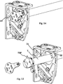
- Figures 16 and 17 show two ways to mount the actuator bar.
- the invention refers to a blind structure which comprises a roller T canvas L awning, a front bar F extension of the canvas L and two arms B articulated extension of the front bar F.
- the ends of the arms B are hinge parts SB, provided with an axis on which the arms B can pivot for their deployment.
- the structure is completed by lateral supports S which support the reel T and the hinge parts SB of the arms B.
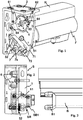
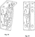
- the lateral supports S are parts consisting of a posterior fixing plate 1 intended to be fixed to a vertical surface, an upper fixing plate 2 which extends perpendicular to the posterior fixing plate 1 by the upper part of the latter, so that an inverted L is formed between the two, and a separating plate 3 connected to the rear fixing plate 1 and to the upper fixing plate 2 and perpendicular to both, said plates forming a single piece which can be cast iron.
- the three plates 1, 2, 3 are arranged so that two separate spaces V1, V2 on either side of the separating plate 3 are formed between them, namely, that the separating plate separates the space in two sides.
- the reel T, the box H (although it is optional) and the arms with their SB hinge supports will be arranged on one of them.
- the fastening components of these elements will be arranged on the other side.
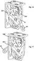
- the separating plate 3 is provided with an opening 4 for the end of the reel T and openings 5, 51, 52 for fixing the hinge parts SB of the ends of the arms B.
- the fastening means 6 of the winder T and the attachment means 7 of the hinge parts SB are arranged on one of the spaces V1, the box of the winder T and the parts of articulation SB of the ends of the arms B being arranged on the other space V2.
- the structure comprises a housing H housing the winder T, also attached to the lateral supports S.
- the separating plate 3 comprises fixing holes 31, 32, two of them are concentric grooves 31 in the form of an arc so that the box H can be mounted in different inclinations, and three others 32 are simple orifices mounted on a circular arc so as to determine three positions of the box H corresponding to three different inclinations.
- the figures 4 and 5 where the Figures 7 and 8 show different inclinations of the awning.
- the fastening means 6 of the reel T to the plate 3 comprise a reversible fork 61 whose central body 63 is connected to the reel T and whose tabs 64 are connected to the plate 3.
- This reversible fork cooperates with shoulders 62 which are integral with the plate 3 for fixing its legs 64.
- figure 1 shows a form of attachment of the fork, for the end where there is no maneuver.
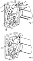
- Figures 14 to 17 show the fork 6 'mounted in the other position, so as to accommodate a worm drive device.
- the shoulders 62 of the plate 3 are made so that it is not possible to improperly mount the plate or central body 63.
- one of the two legs 64 is shorter than the other, and the legs are embedded in the shoulders 62 so that once positioned they can not move, being only necessary to block it with two screws. This greatly facilitates the installation work and avoids any possible error of assembly.
- the separating plate 3 comprises a thru-adjusting groove 52 and the attachment means 7 of the hinge parts SB comprise a worm 72 and a support frame 71 of the worm 72, a slide 73 coupled with the worm 72 and a screw 74 which connects the slide 73 to the hinge parts SB of the ends of the arms B.
- the support frame 71 of the worm 72 is part of the plate 3 separating.
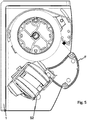
- the hinge parts SB of the ends of the arms B comprise two wheels 8 for adjusting the inclination of the hinge parts SB.
- At least one of the posterior attachment plates 1 comprises an opening AC1 for the passage of a bar 9 for operating the reel T, provided at its end with an operating ring 91 for a crank.
- This opening AC1 is interesting if one wants to mount the maneuvering bar as it is shown on the figure 17 .
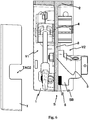
- TL lateral covers recessed in the lateral supports S are also provided on the space V1 side where the fixing means 6 of the reel T and the fastening means 7 of the hinge parts SB are housed, so that cover.
- the configuration of the lateral supports S allows a perfect embedding of the side covers.
- the covers TL comprise a notch AC2 for the passage of the rotation actuating bar 9 of the winder T.
- the cache whose notch is not used for the passage of the bar 91 Actuating rotation of the winder T will advantageously be provided with a TAC2 cover.
- the Figures 18 and 19 show in isolation one of the lateral supports.
Landscapes
- Engineering & Computer Science (AREA)
- Architecture (AREA)
- Civil Engineering (AREA)
- Structural Engineering (AREA)
- Building Awnings And Sunshades (AREA)
Claims (14)
- Markisenstruktur, aufweisend eine Aufrolleinrichtung (T) eines Tuchs (L) einer Markise, eine vordere Strebe (F) zum Ausziehen des Tuchs (L), zwei gelenkige Verlängerungsarme (B) der vorderen Strebe (F), Gelenkstücke (SB) der Enden der Arme (B), seitliche Stützen (S) der Aufrolleinrichtung (T) und Gelenkstücke (SB) der Arme (B), wobei die seitlichen Stützen (S) Stücke sind, die von einer hinteren Befestigungsplatte (1), die an einer vertikalen Fläche befestigt werden soll, einer oberen Befestigungsplatte (2), die sich senkrecht zur hinteren Befestigungsplatte (1) durch den oberen Teil dieser derart fortsetzt, dass sich zwischen den beiden ein umgekehrtes L bildet, sowie einer Trennplatte (3) gebildet werden, die mit der hinteren Befestigungsplatte (1) und der oberen Befestigungsplatte (2) verbunden ist und senkrecht zu den beiden verläuft, so dass zwei getrennte Räume (V1, V2) beiderseits der Platte (3) zwischen den drei Platten (1, 2, 3) gebildet werden, wobei die Trennplatte (3) mit einer Öffnung (4) für das Ende der Aufrolleinrichtung (T) und mit Öffnungen (5, 51, 52) zum Befestigen der Gelenkstücke (SB) der Enden der Arme (B) versehen ist, und Befestigungsmittel (6) der Aufrolleinrichtung (T) an der Trennplatte und Befestigungsmittel (7) der Gelenkstücke (SB) der Enden der Arme (B) an der Trennplatte (3) aufweist, wobei die Befestigungsmittel (6) der Aufrolleinrichtung (T) und die Befestigungsmittel (7) der Gelenkstücke (SB) in einem der Räume (V1) angeordnet sind, wobei der Kasten der Aufrolleinrichtung (T) und die Gelenkstücke (SB) der Enden der Arme (B) in dem anderen Raum (V2) angeordnet sind, dadurch gekennzeichnet, dass die hintere Befestigungsplatte (1), die obere Befestigungsplatte (2) und die Trennplatte (3) ein einziges Teil bilden.
- Struktur nach einem der vorstehenden Ansprüche, aufweisend einen Kasten (H) zur Aufnahme der Aufrolleinrichtung (T), wobei der Kasten (H) an den seitlichen Stützen (S) befestigt ist.
- Struktur nach einem der vorstehenden Ansprüche, wobei die Befestigungsmittel (6) der Aufrolleinrichtung (T) an der Platte (3) eine reversible Gabel (61) aufweisen, deren Hauptkörper (63) mit der Aufrolleinrichtung (T) verbunden ist und deren Laschen (64) mit der Platte (3) verbunden sind.
- Struktur nach Anspruch 3, wobei die Platte (3) Vorsprünge (62) zur Befestigung der Laschen (64) der Gabel (61) aufweist.
- Struktur nach Anspruch 4, wobei die Vorsprünge (62) einstückig mit der Platte (3) sind.
- Struktur nach einem der vorstehenden Ansprüche, wobei die Trennplatte (3) eine Einstell-Quernut (52) aufweist, und die Befestigungsmittel (7) der Gelenkstücke (SB) eine Schnecke (72) und einen Tragrahmen (71) der Schnecke (72), eine mit der Schnecke (72) gekoppelte Laufschiene (73) und eine Schraube (74), die die Laufschiene (73) mit den Gelenkstücken (SB) der Enden der Arme (B) verbindet, aufweisen.
- Struktur nach Anspruch 6, wobei der Tragrahmen (71) der Schnecke (72) ein Teil der Trennplatte (3) ist.
- Struktur nach einem der vorstehenden Ansprüche, wobei die Gelenkstücke (SB) der Enden der Arme (B) zwei Räder (8) zum Einstellen der Neigung der Gelenkstücke (SB) aufweisen.
- Struktur nach einem der vorstehenden Ansprüche, wobei mindestens eine der hinteren Befestigungsplatten (1) eine Öffnung (AC1) für den Durchtritt einer Stange (9) zur Betätigung der Drehung der Aufrollreinrichtung (T) aufweist.
- Struktur nach einem der vorstehenden Ansprüche, aufweisend seitliche Blenden (TL), die in die seitlichen Stützen (S) auf Seiten des Raums (V1), wo die Befestigungsmittel (6) der Aufrolleinrichtung (T) und die Befestigungsmittel (7) der Gelenkstücke (SB) aufgenommen sind, derart eingebettet sind, dass sie diese bedecken.
- Struktur nach Anspruch 10, wobei zumindest eine der Blenden (TL) eine Ausnehmung (AC2) zum Durchtritt einer Stange (9) zur Betätigung der Drehung der Aufrollreinrichtung (T) aufweist.
- Struktur nach Anspruch 2, wobei die Trennplatte (3) Befestigungsöffnungen (31, 32) für den Kasten (H) aufweist.
- Struktur nach Anspruch 12, wobei die zwei Befestigungsöffnungen (31) des Kastens (H) konzentrische Nuten (31) in Kreisbogenform derart sind, dass der Kasten (H) mit unterschiedlichen Neigungen montiert werden kann.
- Struktur nach Anspruch 12 oder 13, aufweisend drei Befestigungsöffnungen (32), die derart auf einem Kreisbogen angeordnet sind, dass sie drei Positionen des Kastens (H) definieren, die drei unterschiedlichen Neigungen entsprechen.
Applications Claiming Priority (1)
| Application Number | Priority Date | Filing Date | Title |
|---|---|---|---|
| ES201730232U ES1179458Y (es) | 2017-03-06 | 2017-03-06 | Estructura de toldo |
Publications (2)
| Publication Number | Publication Date |
|---|---|
| EP3372747A1 EP3372747A1 (de) | 2018-09-12 |
| EP3372747B1 true EP3372747B1 (de) | 2019-10-23 |
Family
ID=59021634
Family Applications (1)
| Application Number | Title | Priority Date | Filing Date |
|---|---|---|---|
| EP18160354.9A Active EP3372747B1 (de) | 2017-03-06 | 2018-03-06 | Markisenstruktur |
Country Status (2)
| Country | Link |
|---|---|
| EP (1) | EP3372747B1 (de) |
| ES (1) | ES1179458Y (de) |
Family Cites Families (3)
| Publication number | Priority date | Publication date | Assignee | Title |
|---|---|---|---|---|
| ES2361347B1 (es) * | 2007-08-06 | 2012-04-20 | Llaza, S.A. | Dispositivo de soporte para toldo enrollable. |
| EP2599931B1 (de) * | 2011-11-30 | 2017-12-20 | Llaza World, S.A. | Aufbau einer ausziehbaren Markise und Stützvorrichtung für eine ausziehbare Markise |
| ES1131130Y (es) * | 2014-10-16 | 2015-01-22 | Producciones Mitjavila Sa | Toldo plegable |
-
2017
- 2017-03-06 ES ES201730232U patent/ES1179458Y/es active Active
-
2018
- 2018-03-06 EP EP18160354.9A patent/EP3372747B1/de active Active
Non-Patent Citations (1)
| Title |
|---|
| None * |
Also Published As
| Publication number | Publication date |
|---|---|
| ES1179458Y (es) | 2017-06-16 |
| EP3372747A1 (de) | 2018-09-12 |
| ES1179458U (es) | 2017-03-24 |
Similar Documents
| Publication | Publication Date | Title |
|---|---|---|
| EP3756501B1 (de) | Befestigungsvorrichtung für armband | |
| EP3000511B1 (de) | Ferseneinheit für schuhbindung auf einem gleitbrett | |
| FR2815477A1 (fr) | Supports pour la fixation sur un mat d'une ou plusieurs antennes relais de systemes de radio-telecommunication cellulaire et dispositi pour le reglage de l'orientation d'une telle antenne | |
| FR2885589A1 (fr) | Dispositif de fixation d'une selle sur une tete de tige de selle | |
| EP3561608A1 (de) | Befestigungsleiste eines armbands an einer armbanduhr, die mit zwei einziehbaren drehzapfen ausgestattet ist | |
| EP0865742B1 (de) | Faltverschluss für Armbänder | |
| EP3372747B1 (de) | Markisenstruktur | |
| EP4159080B1 (de) | Verstellbarer armbandverschluss | |
| EP2980631A1 (de) | Scharnier ohne drehschraube für brillengestell | |
| CA2716389C (fr) | Dispositif a caisson mobile | |
| EP0931710A1 (de) | Kinderwagen mit teleskopisch verlängerbarer Hängematte und korrespondierende Hängematte | |
| EP2212490A2 (de) | Vorrichtung zur befestigung von dachelementen einer teleskopischen überdachung für ein schwimmbecken am boden | |
| EP2927388B1 (de) | Befestigungsvorrichtung für eine markise | |
| WO2004040356A1 (fr) | Ecran pour lunettes et pieces pour la fabrication d'un tel ecran | |
| EP3785772A1 (de) | Haltevorrichtungen für gleitbrett | |
| EP3540143A1 (de) | Markise mit regulierbarer seitlicher halterung | |
| EP0156663A1 (de) | Vorrichtung zum Hemmen des Rücklaufes von Skiern | |
| FR2735878A1 (fr) | Monture de lunettes | |
| FR2716014A1 (fr) | Monture de lunettes à trois positions des branches. | |
| FR2893722A3 (fr) | Lunettes a branches transformables | |
| FR2641664A1 (fr) | Appareil pour le travail du sol, notamment pour travaux forestiers | |
| FR2831456A1 (fr) | Plaque de support pour element de retenue d'une chaussure sur une planche de glisse | |
| EP0553032A1 (de) | Pflugkorp und Pflug mit mindestens einem solchen Pflugkorp | |
| EP1236386B1 (de) | Bodenbearbeitungsgerät, -gestell und -maschine | |
| WO2025083501A1 (fr) | Fermoir à boucle déployante pour bracelet notamment d'une montre |
Legal Events
| Date | Code | Title | Description |
|---|---|---|---|
| PUAI | Public reference made under article 153(3) epc to a published international application that has entered the european phase |
Free format text: ORIGINAL CODE: 0009012 |
|
| STAA | Information on the status of an ep patent application or granted ep patent |
Free format text: STATUS: THE APPLICATION HAS BEEN PUBLISHED |
|
| AK | Designated contracting states |
Kind code of ref document: A1 Designated state(s): AL AT BE BG CH CY CZ DE DK EE ES FI FR GB GR HR HU IE IS IT LI LT LU LV MC MK MT NL NO PL PT RO RS SE SI SK SM TR |
|
| AX | Request for extension of the european patent |
Extension state: BA ME |
|
| STAA | Information on the status of an ep patent application or granted ep patent |
Free format text: STATUS: REQUEST FOR EXAMINATION WAS MADE |
|
| 17P | Request for examination filed |
Effective date: 20181226 |
|
| RBV | Designated contracting states (corrected) |
Designated state(s): AL AT BE BG CH CY CZ DE DK EE ES FI FR GB GR HR HU IE IS IT LI LT LU LV MC MK MT NL NO PL PT RO RS SE SI SK SM TR |
|
| GRAP | Despatch of communication of intention to grant a patent |
Free format text: ORIGINAL CODE: EPIDOSNIGR1 |
|
| STAA | Information on the status of an ep patent application or granted ep patent |
Free format text: STATUS: GRANT OF PATENT IS INTENDED |
|
| INTG | Intention to grant announced |
Effective date: 20190606 |
|
| GRAJ | Information related to disapproval of communication of intention to grant by the applicant or resumption of examination proceedings by the epo deleted |
Free format text: ORIGINAL CODE: EPIDOSDIGR1 |
|
| STAA | Information on the status of an ep patent application or granted ep patent |
Free format text: STATUS: REQUEST FOR EXAMINATION WAS MADE |
|
| INTC | Intention to grant announced (deleted) | ||
| GRAR | Information related to intention to grant a patent recorded |
Free format text: ORIGINAL CODE: EPIDOSNIGR71 |
|
| GRAS | Grant fee paid |
Free format text: ORIGINAL CODE: EPIDOSNIGR3 |
|
| STAA | Information on the status of an ep patent application or granted ep patent |
Free format text: STATUS: GRANT OF PATENT IS INTENDED |
|
| GRAA | (expected) grant |
Free format text: ORIGINAL CODE: 0009210 |
|
| STAA | Information on the status of an ep patent application or granted ep patent |
Free format text: STATUS: THE PATENT HAS BEEN GRANTED |
|
| INTG | Intention to grant announced |
Effective date: 20190912 |
|
| AK | Designated contracting states |
Kind code of ref document: B1 Designated state(s): AL AT BE BG CH CY CZ DE DK EE ES FI FR GB GR HR HU IE IS IT LI LT LU LV MC MK MT NL NO PL PT RO RS SE SI SK SM TR |
|
| REG | Reference to a national code |
Ref country code: GB Ref legal event code: FG4D Free format text: NOT ENGLISH |
|
| REG | Reference to a national code |
Ref country code: CH Ref legal event code: EP |
|
| REG | Reference to a national code |
Ref country code: IE Ref legal event code: FG4D Free format text: LANGUAGE OF EP DOCUMENT: FRENCH |
|
| REG | Reference to a national code |
Ref country code: DE Ref legal event code: R096 Ref document number: 602018000934 Country of ref document: DE |
|
| REG | Reference to a national code |
Ref country code: AT Ref legal event code: REF Ref document number: 1193780 Country of ref document: AT Kind code of ref document: T Effective date: 20191115 |
|
| REG | Reference to a national code |
Ref country code: NL Ref legal event code: MP Effective date: 20191023 |
|
| REG | Reference to a national code |
Ref country code: LT Ref legal event code: MG4D |
|
| PG25 | Lapsed in a contracting state [announced via postgrant information from national office to epo] |
Ref country code: PT Free format text: LAPSE BECAUSE OF FAILURE TO SUBMIT A TRANSLATION OF THE DESCRIPTION OR TO PAY THE FEE WITHIN THE PRESCRIBED TIME-LIMIT Effective date: 20200224 Ref country code: SE Free format text: LAPSE BECAUSE OF FAILURE TO SUBMIT A TRANSLATION OF THE DESCRIPTION OR TO PAY THE FEE WITHIN THE PRESCRIBED TIME-LIMIT Effective date: 20191023 Ref country code: LV Free format text: LAPSE BECAUSE OF FAILURE TO SUBMIT A TRANSLATION OF THE DESCRIPTION OR TO PAY THE FEE WITHIN THE PRESCRIBED TIME-LIMIT Effective date: 20191023 Ref country code: FI Free format text: LAPSE BECAUSE OF FAILURE TO SUBMIT A TRANSLATION OF THE DESCRIPTION OR TO PAY THE FEE WITHIN THE PRESCRIBED TIME-LIMIT Effective date: 20191023 Ref country code: BG Free format text: LAPSE BECAUSE OF FAILURE TO SUBMIT A TRANSLATION OF THE DESCRIPTION OR TO PAY THE FEE WITHIN THE PRESCRIBED TIME-LIMIT Effective date: 20200123 Ref country code: PL Free format text: LAPSE BECAUSE OF FAILURE TO SUBMIT A TRANSLATION OF THE DESCRIPTION OR TO PAY THE FEE WITHIN THE PRESCRIBED TIME-LIMIT Effective date: 20191023 Ref country code: LT Free format text: LAPSE BECAUSE OF FAILURE TO SUBMIT A TRANSLATION OF THE DESCRIPTION OR TO PAY THE FEE WITHIN THE PRESCRIBED TIME-LIMIT Effective date: 20191023 Ref country code: GR Free format text: LAPSE BECAUSE OF FAILURE TO SUBMIT A TRANSLATION OF THE DESCRIPTION OR TO PAY THE FEE WITHIN THE PRESCRIBED TIME-LIMIT Effective date: 20200124 Ref country code: NO Free format text: LAPSE BECAUSE OF FAILURE TO SUBMIT A TRANSLATION OF THE DESCRIPTION OR TO PAY THE FEE WITHIN THE PRESCRIBED TIME-LIMIT Effective date: 20200123 Ref country code: NL Free format text: LAPSE BECAUSE OF FAILURE TO SUBMIT A TRANSLATION OF THE DESCRIPTION OR TO PAY THE FEE WITHIN THE PRESCRIBED TIME-LIMIT Effective date: 20191023 |
|
| PG25 | Lapsed in a contracting state [announced via postgrant information from national office to epo] |
Ref country code: RS Free format text: LAPSE BECAUSE OF FAILURE TO SUBMIT A TRANSLATION OF THE DESCRIPTION OR TO PAY THE FEE WITHIN THE PRESCRIBED TIME-LIMIT Effective date: 20191023 Ref country code: IS Free format text: LAPSE BECAUSE OF FAILURE TO SUBMIT A TRANSLATION OF THE DESCRIPTION OR TO PAY THE FEE WITHIN THE PRESCRIBED TIME-LIMIT Effective date: 20200224 Ref country code: HR Free format text: LAPSE BECAUSE OF FAILURE TO SUBMIT A TRANSLATION OF THE DESCRIPTION OR TO PAY THE FEE WITHIN THE PRESCRIBED TIME-LIMIT Effective date: 20191023 |
|
| PG25 | Lapsed in a contracting state [announced via postgrant information from national office to epo] |
Ref country code: AL Free format text: LAPSE BECAUSE OF FAILURE TO SUBMIT A TRANSLATION OF THE DESCRIPTION OR TO PAY THE FEE WITHIN THE PRESCRIBED TIME-LIMIT Effective date: 20191023 |
|
| REG | Reference to a national code |
Ref country code: DE Ref legal event code: R097 Ref document number: 602018000934 Country of ref document: DE |
|
| PG2D | Information on lapse in contracting state deleted |
Ref country code: IS |
|
| PG25 | Lapsed in a contracting state [announced via postgrant information from national office to epo] |
Ref country code: EE Free format text: LAPSE BECAUSE OF FAILURE TO SUBMIT A TRANSLATION OF THE DESCRIPTION OR TO PAY THE FEE WITHIN THE PRESCRIBED TIME-LIMIT Effective date: 20191023 Ref country code: DK Free format text: LAPSE BECAUSE OF FAILURE TO SUBMIT A TRANSLATION OF THE DESCRIPTION OR TO PAY THE FEE WITHIN THE PRESCRIBED TIME-LIMIT Effective date: 20191023 Ref country code: RO Free format text: LAPSE BECAUSE OF FAILURE TO SUBMIT A TRANSLATION OF THE DESCRIPTION OR TO PAY THE FEE WITHIN THE PRESCRIBED TIME-LIMIT Effective date: 20191023 Ref country code: CZ Free format text: LAPSE BECAUSE OF FAILURE TO SUBMIT A TRANSLATION OF THE DESCRIPTION OR TO PAY THE FEE WITHIN THE PRESCRIBED TIME-LIMIT Effective date: 20191023 Ref country code: ES Free format text: LAPSE BECAUSE OF FAILURE TO SUBMIT A TRANSLATION OF THE DESCRIPTION OR TO PAY THE FEE WITHIN THE PRESCRIBED TIME-LIMIT Effective date: 20191023 Ref country code: IS Free format text: LAPSE BECAUSE OF FAILURE TO SUBMIT A TRANSLATION OF THE DESCRIPTION OR TO PAY THE FEE WITHIN THE PRESCRIBED TIME-LIMIT Effective date: 20200223 |
|
| REG | Reference to a national code |
Ref country code: AT Ref legal event code: MK05 Ref document number: 1193780 Country of ref document: AT Kind code of ref document: T Effective date: 20191023 |
|
| PLBE | No opposition filed within time limit |
Free format text: ORIGINAL CODE: 0009261 |
|
| STAA | Information on the status of an ep patent application or granted ep patent |
Free format text: STATUS: NO OPPOSITION FILED WITHIN TIME LIMIT |
|
| PG25 | Lapsed in a contracting state [announced via postgrant information from national office to epo] |
Ref country code: SM Free format text: LAPSE BECAUSE OF FAILURE TO SUBMIT A TRANSLATION OF THE DESCRIPTION OR TO PAY THE FEE WITHIN THE PRESCRIBED TIME-LIMIT Effective date: 20191023 Ref country code: IT Free format text: LAPSE BECAUSE OF FAILURE TO SUBMIT A TRANSLATION OF THE DESCRIPTION OR TO PAY THE FEE WITHIN THE PRESCRIBED TIME-LIMIT Effective date: 20191023 Ref country code: SK Free format text: LAPSE BECAUSE OF FAILURE TO SUBMIT A TRANSLATION OF THE DESCRIPTION OR TO PAY THE FEE WITHIN THE PRESCRIBED TIME-LIMIT Effective date: 20191023 |
|
| 26N | No opposition filed |
Effective date: 20200724 |
|
| REG | Reference to a national code |
Ref country code: DE Ref legal event code: R119 Ref document number: 602018000934 Country of ref document: DE |
|
| PG25 | Lapsed in a contracting state [announced via postgrant information from national office to epo] |
Ref country code: MC Free format text: LAPSE BECAUSE OF FAILURE TO SUBMIT A TRANSLATION OF THE DESCRIPTION OR TO PAY THE FEE WITHIN THE PRESCRIBED TIME-LIMIT Effective date: 20191023 |
|
| PG25 | Lapsed in a contracting state [announced via postgrant information from national office to epo] |
Ref country code: AT Free format text: LAPSE BECAUSE OF FAILURE TO SUBMIT A TRANSLATION OF THE DESCRIPTION OR TO PAY THE FEE WITHIN THE PRESCRIBED TIME-LIMIT Effective date: 20191023 Ref country code: SI Free format text: LAPSE BECAUSE OF FAILURE TO SUBMIT A TRANSLATION OF THE DESCRIPTION OR TO PAY THE FEE WITHIN THE PRESCRIBED TIME-LIMIT Effective date: 20191023 |
|
| REG | Reference to a national code |
Ref country code: BE Ref legal event code: MM Effective date: 20200331 |
|
| PG25 | Lapsed in a contracting state [announced via postgrant information from national office to epo] |
Ref country code: LU Free format text: LAPSE BECAUSE OF NON-PAYMENT OF DUE FEES Effective date: 20200306 |
|
| PG25 | Lapsed in a contracting state [announced via postgrant information from national office to epo] |
Ref country code: FR Free format text: LAPSE BECAUSE OF NON-PAYMENT OF DUE FEES Effective date: 20200331 Ref country code: DE Free format text: LAPSE BECAUSE OF NON-PAYMENT OF DUE FEES Effective date: 20201001 Ref country code: IE Free format text: LAPSE BECAUSE OF NON-PAYMENT OF DUE FEES Effective date: 20200306 |
|
| PG25 | Lapsed in a contracting state [announced via postgrant information from national office to epo] |
Ref country code: BE Free format text: LAPSE BECAUSE OF NON-PAYMENT OF DUE FEES Effective date: 20200331 |
|
| REG | Reference to a national code |
Ref country code: CH Ref legal event code: PL |
|
| PG25 | Lapsed in a contracting state [announced via postgrant information from national office to epo] |
Ref country code: CH Free format text: LAPSE BECAUSE OF NON-PAYMENT OF DUE FEES Effective date: 20210331 Ref country code: LI Free format text: LAPSE BECAUSE OF NON-PAYMENT OF DUE FEES Effective date: 20210331 |
|
| PG25 | Lapsed in a contracting state [announced via postgrant information from national office to epo] |
Ref country code: TR Free format text: LAPSE BECAUSE OF FAILURE TO SUBMIT A TRANSLATION OF THE DESCRIPTION OR TO PAY THE FEE WITHIN THE PRESCRIBED TIME-LIMIT Effective date: 20191023 Ref country code: MT Free format text: LAPSE BECAUSE OF FAILURE TO SUBMIT A TRANSLATION OF THE DESCRIPTION OR TO PAY THE FEE WITHIN THE PRESCRIBED TIME-LIMIT Effective date: 20191023 Ref country code: CY Free format text: LAPSE BECAUSE OF FAILURE TO SUBMIT A TRANSLATION OF THE DESCRIPTION OR TO PAY THE FEE WITHIN THE PRESCRIBED TIME-LIMIT Effective date: 20191023 |
|
| PG25 | Lapsed in a contracting state [announced via postgrant information from national office to epo] |
Ref country code: MK Free format text: LAPSE BECAUSE OF FAILURE TO SUBMIT A TRANSLATION OF THE DESCRIPTION OR TO PAY THE FEE WITHIN THE PRESCRIBED TIME-LIMIT Effective date: 20191023 |
|
| GBPC | Gb: european patent ceased through non-payment of renewal fee |
Effective date: 20220306 |
|
| PG25 | Lapsed in a contracting state [announced via postgrant information from national office to epo] |
Ref country code: GB Free format text: LAPSE BECAUSE OF NON-PAYMENT OF DUE FEES Effective date: 20220306 |