EP3372571A2 - Bismuth-containing piezoelectric composition and piezoelectric device - Google Patents
Bismuth-containing piezoelectric composition and piezoelectric device Download PDFInfo
- Publication number
- EP3372571A2 EP3372571A2 EP18160508.0A EP18160508A EP3372571A2 EP 3372571 A2 EP3372571 A2 EP 3372571A2 EP 18160508 A EP18160508 A EP 18160508A EP 3372571 A2 EP3372571 A2 EP 3372571A2
- Authority
- EP
- European Patent Office
- Prior art keywords
- piezoelectric
- core
- raw material
- material particles
- piezoelectric composition
- Prior art date
- Legal status (The legal status is an assumption and is not a legal conclusion. Google has not performed a legal analysis and makes no representation as to the accuracy of the status listed.)
- Granted
Links
Images


Classifications
-
- H—ELECTRICITY
- H10—SEMICONDUCTOR DEVICES; ELECTRIC SOLID-STATE DEVICES NOT OTHERWISE PROVIDED FOR
- H10N—ELECTRIC SOLID-STATE DEVICES NOT OTHERWISE PROVIDED FOR
- H10N30/00—Piezoelectric or electrostrictive devices
- H10N30/80—Constructional details
- H10N30/85—Piezoelectric or electrostrictive active materials
- H10N30/853—Ceramic compositions
- H10N30/8561—Bismuth-based oxides
-
- C—CHEMISTRY; METALLURGY
- C01—INORGANIC CHEMISTRY
- C01G—COMPOUNDS CONTAINING METALS NOT COVERED BY SUBCLASSES C01D OR C01F
- C01G23/00—Compounds of titanium
- C01G23/003—Titanates
- C01G23/006—Alkaline earth titanates
-
- C—CHEMISTRY; METALLURGY
- C01—INORGANIC CHEMISTRY
- C01G—COMPOUNDS CONTAINING METALS NOT COVERED BY SUBCLASSES C01D OR C01F
- C01G49/00—Compounds of iron
- C01G49/0018—Mixed oxides or hydroxides
-
- C—CHEMISTRY; METALLURGY
- C04—CEMENTS; CONCRETE; ARTIFICIAL STONE; CERAMICS; REFRACTORIES
- C04B—LIME, MAGNESIA; SLAG; CEMENTS; COMPOSITIONS THEREOF, e.g. MORTARS, CONCRETE OR LIKE BUILDING MATERIALS; ARTIFICIAL STONE; CERAMICS; REFRACTORIES; TREATMENT OF NATURAL STONE
- C04B35/00—Shaped ceramic products characterised by their composition; Ceramics compositions; Processing powders of inorganic compounds preparatory to the manufacturing of ceramic products
- C04B35/01—Shaped ceramic products characterised by their composition; Ceramics compositions; Processing powders of inorganic compounds preparatory to the manufacturing of ceramic products based on oxide ceramics
- C04B35/26—Shaped ceramic products characterised by their composition; Ceramics compositions; Processing powders of inorganic compounds preparatory to the manufacturing of ceramic products based on oxide ceramics based on ferrites
-
- C—CHEMISTRY; METALLURGY
- C04—CEMENTS; CONCRETE; ARTIFICIAL STONE; CERAMICS; REFRACTORIES
- C04B—LIME, MAGNESIA; SLAG; CEMENTS; COMPOSITIONS THEREOF, e.g. MORTARS, CONCRETE OR LIKE BUILDING MATERIALS; ARTIFICIAL STONE; CERAMICS; REFRACTORIES; TREATMENT OF NATURAL STONE
- C04B35/00—Shaped ceramic products characterised by their composition; Ceramics compositions; Processing powders of inorganic compounds preparatory to the manufacturing of ceramic products
- C04B35/01—Shaped ceramic products characterised by their composition; Ceramics compositions; Processing powders of inorganic compounds preparatory to the manufacturing of ceramic products based on oxide ceramics
- C04B35/26—Shaped ceramic products characterised by their composition; Ceramics compositions; Processing powders of inorganic compounds preparatory to the manufacturing of ceramic products based on oxide ceramics based on ferrites
- C04B35/2683—Other ferrites containing alkaline earth metals or lead
-
- C—CHEMISTRY; METALLURGY
- C04—CEMENTS; CONCRETE; ARTIFICIAL STONE; CERAMICS; REFRACTORIES
- C04B—LIME, MAGNESIA; SLAG; CEMENTS; COMPOSITIONS THEREOF, e.g. MORTARS, CONCRETE OR LIKE BUILDING MATERIALS; ARTIFICIAL STONE; CERAMICS; REFRACTORIES; TREATMENT OF NATURAL STONE
- C04B35/00—Shaped ceramic products characterised by their composition; Ceramics compositions; Processing powders of inorganic compounds preparatory to the manufacturing of ceramic products
- C04B35/01—Shaped ceramic products characterised by their composition; Ceramics compositions; Processing powders of inorganic compounds preparatory to the manufacturing of ceramic products based on oxide ceramics
- C04B35/46—Shaped ceramic products characterised by their composition; Ceramics compositions; Processing powders of inorganic compounds preparatory to the manufacturing of ceramic products based on oxide ceramics based on titanium oxides or titanates
- C04B35/462—Shaped ceramic products characterised by their composition; Ceramics compositions; Processing powders of inorganic compounds preparatory to the manufacturing of ceramic products based on oxide ceramics based on titanium oxides or titanates based on titanates
- C04B35/465—Shaped ceramic products characterised by their composition; Ceramics compositions; Processing powders of inorganic compounds preparatory to the manufacturing of ceramic products based on oxide ceramics based on titanium oxides or titanates based on titanates based on alkaline earth metal titanates
- C04B35/468—Shaped ceramic products characterised by their composition; Ceramics compositions; Processing powders of inorganic compounds preparatory to the manufacturing of ceramic products based on oxide ceramics based on titanium oxides or titanates based on titanates based on alkaline earth metal titanates based on barium titanates
- C04B35/4682—Shaped ceramic products characterised by their composition; Ceramics compositions; Processing powders of inorganic compounds preparatory to the manufacturing of ceramic products based on oxide ceramics based on titanium oxides or titanates based on titanates based on alkaline earth metal titanates based on barium titanates based on BaTiO3 perovskite phase
-
- C—CHEMISTRY; METALLURGY
- C04—CEMENTS; CONCRETE; ARTIFICIAL STONE; CERAMICS; REFRACTORIES
- C04B—LIME, MAGNESIA; SLAG; CEMENTS; COMPOSITIONS THEREOF, e.g. MORTARS, CONCRETE OR LIKE BUILDING MATERIALS; ARTIFICIAL STONE; CERAMICS; REFRACTORIES; TREATMENT OF NATURAL STONE
- C04B35/00—Shaped ceramic products characterised by their composition; Ceramics compositions; Processing powders of inorganic compounds preparatory to the manufacturing of ceramic products
- C04B35/622—Forming processes; Processing powders of inorganic compounds preparatory to the manufacturing of ceramic products
-
- C—CHEMISTRY; METALLURGY
- C04—CEMENTS; CONCRETE; ARTIFICIAL STONE; CERAMICS; REFRACTORIES
- C04B—LIME, MAGNESIA; SLAG; CEMENTS; COMPOSITIONS THEREOF, e.g. MORTARS, CONCRETE OR LIKE BUILDING MATERIALS; ARTIFICIAL STONE; CERAMICS; REFRACTORIES; TREATMENT OF NATURAL STONE
- C04B35/00—Shaped ceramic products characterised by their composition; Ceramics compositions; Processing powders of inorganic compounds preparatory to the manufacturing of ceramic products
- C04B35/622—Forming processes; Processing powders of inorganic compounds preparatory to the manufacturing of ceramic products
- C04B35/626—Preparing or treating the powders individually or as batches ; preparing or treating macroscopic reinforcing agents for ceramic products, e.g. fibres; mechanical aspects section B
- C04B35/628—Coating the powders or the macroscopic reinforcing agents
- C04B35/62802—Powder coating materials
- C04B35/62805—Oxide ceramics
-
- C—CHEMISTRY; METALLURGY
- C04—CEMENTS; CONCRETE; ARTIFICIAL STONE; CERAMICS; REFRACTORIES
- C04B—LIME, MAGNESIA; SLAG; CEMENTS; COMPOSITIONS THEREOF, e.g. MORTARS, CONCRETE OR LIKE BUILDING MATERIALS; ARTIFICIAL STONE; CERAMICS; REFRACTORIES; TREATMENT OF NATURAL STONE
- C04B35/00—Shaped ceramic products characterised by their composition; Ceramics compositions; Processing powders of inorganic compounds preparatory to the manufacturing of ceramic products
- C04B35/622—Forming processes; Processing powders of inorganic compounds preparatory to the manufacturing of ceramic products
- C04B35/626—Preparing or treating the powders individually or as batches ; preparing or treating macroscopic reinforcing agents for ceramic products, e.g. fibres; mechanical aspects section B
- C04B35/628—Coating the powders or the macroscopic reinforcing agents
- C04B35/62802—Powder coating materials
- C04B35/62805—Oxide ceramics
- C04B35/62818—Refractory metal oxides
- C04B35/62821—Titanium oxide
-
- C—CHEMISTRY; METALLURGY
- C04—CEMENTS; CONCRETE; ARTIFICIAL STONE; CERAMICS; REFRACTORIES
- C04B—LIME, MAGNESIA; SLAG; CEMENTS; COMPOSITIONS THEREOF, e.g. MORTARS, CONCRETE OR LIKE BUILDING MATERIALS; ARTIFICIAL STONE; CERAMICS; REFRACTORIES; TREATMENT OF NATURAL STONE
- C04B35/00—Shaped ceramic products characterised by their composition; Ceramics compositions; Processing powders of inorganic compounds preparatory to the manufacturing of ceramic products
- C04B35/622—Forming processes; Processing powders of inorganic compounds preparatory to the manufacturing of ceramic products
- C04B35/626—Preparing or treating the powders individually or as batches ; preparing or treating macroscopic reinforcing agents for ceramic products, e.g. fibres; mechanical aspects section B
- C04B35/628—Coating the powders or the macroscopic reinforcing agents
- C04B35/62802—Powder coating materials
- C04B35/62805—Oxide ceramics
- C04B35/62826—Iron group metal oxides
-
- H—ELECTRICITY
- H10—SEMICONDUCTOR DEVICES; ELECTRIC SOLID-STATE DEVICES NOT OTHERWISE PROVIDED FOR
- H10N—ELECTRIC SOLID-STATE DEVICES NOT OTHERWISE PROVIDED FOR
- H10N30/00—Piezoelectric or electrostrictive devices
- H10N30/01—Manufacture or treatment
- H10N30/09—Forming piezoelectric or electrostrictive materials
- H10N30/092—Forming composite materials
-
- H—ELECTRICITY
- H10—SEMICONDUCTOR DEVICES; ELECTRIC SOLID-STATE DEVICES NOT OTHERWISE PROVIDED FOR
- H10N—ELECTRIC SOLID-STATE DEVICES NOT OTHERWISE PROVIDED FOR
- H10N30/00—Piezoelectric or electrostrictive devices
- H10N30/01—Manufacture or treatment
- H10N30/09—Forming piezoelectric or electrostrictive materials
- H10N30/093—Forming inorganic materials
- H10N30/097—Forming inorganic materials by sintering
-
- H—ELECTRICITY
- H10—SEMICONDUCTOR DEVICES; ELECTRIC SOLID-STATE DEVICES NOT OTHERWISE PROVIDED FOR
- H10N—ELECTRIC SOLID-STATE DEVICES NOT OTHERWISE PROVIDED FOR
- H10N30/00—Piezoelectric or electrostrictive devices
- H10N30/80—Constructional details
- H10N30/85—Piezoelectric or electrostrictive active materials
- H10N30/853—Ceramic compositions
-
- H—ELECTRICITY
- H10—SEMICONDUCTOR DEVICES; ELECTRIC SOLID-STATE DEVICES NOT OTHERWISE PROVIDED FOR
- H10N—ELECTRIC SOLID-STATE DEVICES NOT OTHERWISE PROVIDED FOR
- H10N30/00—Piezoelectric or electrostrictive devices
- H10N30/80—Constructional details
- H10N30/85—Piezoelectric or electrostrictive active materials
- H10N30/853—Ceramic compositions
- H10N30/8536—Alkaline earth metal based oxides, e.g. barium titanates
-
- H—ELECTRICITY
- H10—SEMICONDUCTOR DEVICES; ELECTRIC SOLID-STATE DEVICES NOT OTHERWISE PROVIDED FOR
- H10N—ELECTRIC SOLID-STATE DEVICES NOT OTHERWISE PROVIDED FOR
- H10N30/00—Piezoelectric or electrostrictive devices
- H10N30/80—Constructional details
- H10N30/87—Electrodes or interconnections, e.g. leads or terminals
- H10N30/877—Conductive materials
-
- C—CHEMISTRY; METALLURGY
- C01—INORGANIC CHEMISTRY
- C01P—INDEXING SCHEME RELATING TO STRUCTURAL AND PHYSICAL ASPECTS OF SOLID INORGANIC COMPOUNDS
- C01P2002/00—Crystal-structural characteristics
- C01P2002/30—Three-dimensional structures
- C01P2002/34—Three-dimensional structures perovskite-type (ABO3)
-
- C—CHEMISTRY; METALLURGY
- C01—INORGANIC CHEMISTRY
- C01P—INDEXING SCHEME RELATING TO STRUCTURAL AND PHYSICAL ASPECTS OF SOLID INORGANIC COMPOUNDS
- C01P2004/00—Particle morphology
- C01P2004/80—Particles consisting of a mixture of two or more inorganic phases
- C01P2004/82—Particles consisting of a mixture of two or more inorganic phases two phases having the same anion, e.g. both oxidic phases
- C01P2004/84—Particles consisting of a mixture of two or more inorganic phases two phases having the same anion, e.g. both oxidic phases one phase coated with the other
-
- C—CHEMISTRY; METALLURGY
- C04—CEMENTS; CONCRETE; ARTIFICIAL STONE; CERAMICS; REFRACTORIES
- C04B—LIME, MAGNESIA; SLAG; CEMENTS; COMPOSITIONS THEREOF, e.g. MORTARS, CONCRETE OR LIKE BUILDING MATERIALS; ARTIFICIAL STONE; CERAMICS; REFRACTORIES; TREATMENT OF NATURAL STONE
- C04B2235/00—Aspects relating to ceramic starting mixtures or sintered ceramic products
- C04B2235/02—Composition of constituents of the starting material or of secondary phases of the final product
- C04B2235/30—Constituents and secondary phases not being of a fibrous nature
- C04B2235/32—Metal oxides, mixed metal oxides, or oxide-forming salts thereof, e.g. carbonates, nitrates, (oxy)hydroxides, chlorides
- C04B2235/3205—Alkaline earth oxides or oxide forming salts thereof, e.g. beryllium oxide
- C04B2235/3215—Barium oxides or oxide-forming salts thereof
-
- C—CHEMISTRY; METALLURGY
- C04—CEMENTS; CONCRETE; ARTIFICIAL STONE; CERAMICS; REFRACTORIES
- C04B—LIME, MAGNESIA; SLAG; CEMENTS; COMPOSITIONS THEREOF, e.g. MORTARS, CONCRETE OR LIKE BUILDING MATERIALS; ARTIFICIAL STONE; CERAMICS; REFRACTORIES; TREATMENT OF NATURAL STONE
- C04B2235/00—Aspects relating to ceramic starting mixtures or sintered ceramic products
- C04B2235/02—Composition of constituents of the starting material or of secondary phases of the final product
- C04B2235/30—Constituents and secondary phases not being of a fibrous nature
- C04B2235/32—Metal oxides, mixed metal oxides, or oxide-forming salts thereof, e.g. carbonates, nitrates, (oxy)hydroxides, chlorides
- C04B2235/3231—Refractory metal oxides, their mixed metal oxides, or oxide-forming salts thereof
- C04B2235/3232—Titanium oxides or titanates, e.g. rutile or anatase
-
- C—CHEMISTRY; METALLURGY
- C04—CEMENTS; CONCRETE; ARTIFICIAL STONE; CERAMICS; REFRACTORIES
- C04B—LIME, MAGNESIA; SLAG; CEMENTS; COMPOSITIONS THEREOF, e.g. MORTARS, CONCRETE OR LIKE BUILDING MATERIALS; ARTIFICIAL STONE; CERAMICS; REFRACTORIES; TREATMENT OF NATURAL STONE
- C04B2235/00—Aspects relating to ceramic starting mixtures or sintered ceramic products
- C04B2235/02—Composition of constituents of the starting material or of secondary phases of the final product
- C04B2235/30—Constituents and secondary phases not being of a fibrous nature
- C04B2235/32—Metal oxides, mixed metal oxides, or oxide-forming salts thereof, e.g. carbonates, nitrates, (oxy)hydroxides, chlorides
- C04B2235/3231—Refractory metal oxides, their mixed metal oxides, or oxide-forming salts thereof
- C04B2235/3232—Titanium oxides or titanates, e.g. rutile or anatase
- C04B2235/3234—Titanates, not containing zirconia
- C04B2235/3236—Alkaline earth titanates
-
- C—CHEMISTRY; METALLURGY
- C04—CEMENTS; CONCRETE; ARTIFICIAL STONE; CERAMICS; REFRACTORIES
- C04B—LIME, MAGNESIA; SLAG; CEMENTS; COMPOSITIONS THEREOF, e.g. MORTARS, CONCRETE OR LIKE BUILDING MATERIALS; ARTIFICIAL STONE; CERAMICS; REFRACTORIES; TREATMENT OF NATURAL STONE
- C04B2235/00—Aspects relating to ceramic starting mixtures or sintered ceramic products
- C04B2235/02—Composition of constituents of the starting material or of secondary phases of the final product
- C04B2235/30—Constituents and secondary phases not being of a fibrous nature
- C04B2235/32—Metal oxides, mixed metal oxides, or oxide-forming salts thereof, e.g. carbonates, nitrates, (oxy)hydroxides, chlorides
- C04B2235/327—Iron group oxides, their mixed metal oxides, or oxide-forming salts thereof
- C04B2235/3272—Iron oxides or oxide forming salts thereof, e.g. hematite, magnetite
-
- C—CHEMISTRY; METALLURGY
- C04—CEMENTS; CONCRETE; ARTIFICIAL STONE; CERAMICS; REFRACTORIES
- C04B—LIME, MAGNESIA; SLAG; CEMENTS; COMPOSITIONS THEREOF, e.g. MORTARS, CONCRETE OR LIKE BUILDING MATERIALS; ARTIFICIAL STONE; CERAMICS; REFRACTORIES; TREATMENT OF NATURAL STONE
- C04B2235/00—Aspects relating to ceramic starting mixtures or sintered ceramic products
- C04B2235/02—Composition of constituents of the starting material or of secondary phases of the final product
- C04B2235/30—Constituents and secondary phases not being of a fibrous nature
- C04B2235/32—Metal oxides, mixed metal oxides, or oxide-forming salts thereof, e.g. carbonates, nitrates, (oxy)hydroxides, chlorides
- C04B2235/3298—Bismuth oxides, bismuthates or oxide forming salts thereof, e.g. zinc bismuthate
-
- C—CHEMISTRY; METALLURGY
- C04—CEMENTS; CONCRETE; ARTIFICIAL STONE; CERAMICS; REFRACTORIES
- C04B—LIME, MAGNESIA; SLAG; CEMENTS; COMPOSITIONS THEREOF, e.g. MORTARS, CONCRETE OR LIKE BUILDING MATERIALS; ARTIFICIAL STONE; CERAMICS; REFRACTORIES; TREATMENT OF NATURAL STONE
- C04B2235/00—Aspects relating to ceramic starting mixtures or sintered ceramic products
- C04B2235/70—Aspects relating to sintered or melt-casted ceramic products
- C04B2235/74—Physical characteristics
- C04B2235/76—Crystal structural characteristics, e.g. symmetry
- C04B2235/768—Perovskite structure ABO3
-
- C—CHEMISTRY; METALLURGY
- C04—CEMENTS; CONCRETE; ARTIFICIAL STONE; CERAMICS; REFRACTORIES
- C04B—LIME, MAGNESIA; SLAG; CEMENTS; COMPOSITIONS THEREOF, e.g. MORTARS, CONCRETE OR LIKE BUILDING MATERIALS; ARTIFICIAL STONE; CERAMICS; REFRACTORIES; TREATMENT OF NATURAL STONE
- C04B2235/00—Aspects relating to ceramic starting mixtures or sintered ceramic products
- C04B2235/70—Aspects relating to sintered or melt-casted ceramic products
- C04B2235/74—Physical characteristics
- C04B2235/78—Grain sizes and shapes, product microstructures, e.g. acicular grains, equiaxed grains, platelet-structures
- C04B2235/785—Submicron sized grains, i.e. from 0,1 to 1 micron
-
- C—CHEMISTRY; METALLURGY
- C04—CEMENTS; CONCRETE; ARTIFICIAL STONE; CERAMICS; REFRACTORIES
- C04B—LIME, MAGNESIA; SLAG; CEMENTS; COMPOSITIONS THEREOF, e.g. MORTARS, CONCRETE OR LIKE BUILDING MATERIALS; ARTIFICIAL STONE; CERAMICS; REFRACTORIES; TREATMENT OF NATURAL STONE
- C04B2235/00—Aspects relating to ceramic starting mixtures or sintered ceramic products
- C04B2235/70—Aspects relating to sintered or melt-casted ceramic products
- C04B2235/74—Physical characteristics
- C04B2235/78—Grain sizes and shapes, product microstructures, e.g. acicular grains, equiaxed grains, platelet-structures
- C04B2235/786—Micrometer sized grains, i.e. from 1 to 100 micron
-
- C—CHEMISTRY; METALLURGY
- C04—CEMENTS; CONCRETE; ARTIFICIAL STONE; CERAMICS; REFRACTORIES
- C04B—LIME, MAGNESIA; SLAG; CEMENTS; COMPOSITIONS THEREOF, e.g. MORTARS, CONCRETE OR LIKE BUILDING MATERIALS; ARTIFICIAL STONE; CERAMICS; REFRACTORIES; TREATMENT OF NATURAL STONE
- C04B2235/00—Aspects relating to ceramic starting mixtures or sintered ceramic products
- C04B2235/70—Aspects relating to sintered or melt-casted ceramic products
- C04B2235/80—Phases present in the sintered or melt-cast ceramic products other than the main phase
-
- C—CHEMISTRY; METALLURGY
- C04—CEMENTS; CONCRETE; ARTIFICIAL STONE; CERAMICS; REFRACTORIES
- C04B—LIME, MAGNESIA; SLAG; CEMENTS; COMPOSITIONS THEREOF, e.g. MORTARS, CONCRETE OR LIKE BUILDING MATERIALS; ARTIFICIAL STONE; CERAMICS; REFRACTORIES; TREATMENT OF NATURAL STONE
- C04B2235/00—Aspects relating to ceramic starting mixtures or sintered ceramic products
- C04B2235/70—Aspects relating to sintered or melt-casted ceramic products
- C04B2235/80—Phases present in the sintered or melt-cast ceramic products other than the main phase
- C04B2235/85—Intergranular or grain boundary phases
Definitions
- the present invention relates to a piezoelectric composition and a piezoelectric device.
- a perovskite-type metal oxide is known as a common piezoelectric composition.
- the composition of a perovskite-type metal oxide is represented by ABO 3 .
- a perovskite-type piezoelectric composition is, for example, lead zirconate titanate (Pb(Zr,Ti)O 3 ).
- the Curie temperature (Tc) of lead zirconate titanate (PZT) is high, and the piezoelectric constant (d 33 ) of PZT is high.
- PZT is harmful to the environment or the human body because it includes lead as an element in the A site.
- the piezoelectric composition not including lead is required in view of influence on the environment or the human body.
- a specific example of a piezoelectric composition not using lead is bismuth ferrite (BiFeO 3 ) described in the following Non Patent Literature 1.
- the Tc of bismuth ferrite (BFO) is high, and BFO exhibits large spontaneous polarization.
- BFO alone the anisotropy is high and the leakage current is large, so sufficient piezoelectric performance (for example, piezoelectric constant d 33 ) is not obtained.
- a piezoelectric composition where the Tc is high and the d 33 is high is required.
- a binary compound composed of barium titanate and bismuth ferrite is disclosed in the following Non Patent Literature 2.
- a ternary compound composed of barium titanate, bismuth ferrite and bismuth magnesate titanate is disclosed in Japanese Unexamined Patent Publication No. 2013-191751 .
- a method for producing a piezoelectric body having the piezoelectricity improved from aggregates of ceramic particles in which the crystal orientation is aligned by a magnetic field is disclosed in Japanese Unexamined Patent Publication No. 2013-95627 .
- Non Patent Literature 1 Tadej Rojac et al., "Strong ferroelectric domain-wall pinning in BiFeO3 ceramics", JOURNAL OF APPLIED PHYSICS, 108, 074107, 2010 .
- Non Patent Literature 2 Zhenyong Cen et al., "Effect of sintering temperature on microstructure and piezoelectric properties of Pb-free BiFeO3-BaTiO3 ceramics in the composition range of large BiFeO3 concentrations", J Electroceram, 31, p. 15-20, 2013 .
- a piezoelectric composition described in Japanese Unexamined Patent Publication 2013-191751 is greatly distorted when a sufficiently high electric field is applied. However, it is difficult for a piezoelectric composition described in Japanese Unexamined Patent Publication No. 2013-191751 to have a sufficiently high piezoelectric constant after a polarization process.
- a polarization process is performed on a piezoelectric composition described in Non Patent Literature 2
- the d 33 of the piezoelectric composition after a polarization process is around 130 pC/N, which is small.
- a bismuth ferrite-based piezoelectric composition produced by a method described in Japanese Unexamined Patent Publication No. 2013-95627 has not been realized.
- the present invention has been completed in view of the above circumstances, and an object of the present invention is to provide a piezoelectric composition where the piezoelectric constant d 33 is high and the Curie temperature Tc is high, and a piezoelectric device using the piezoelectric composition.
- the piezoelectric composition according to one aspect of the present invention is a piezoelectric composition comprising a plurality of crystal particles, wherein the piezoelectric composition includes bismuth, iron, barium, titanium and oxygen; the crystal particle includes a core and a shell having a content of bismuth higher than that in the core and covering the core; and the total area of the cross sections of the cores exposed to the cross section of the piezoelectric composition is expressed as S CORE , the total area of the cross sections of the shells exposed to the cross section of the piezoelectric composition is expressed as S SHELL , and 100.S CORE /(S CORE + S SHELL ) is 50 to 90.
- the number of all the particles comprised in the piezoelectric composition may be expressed as N, the number of the crystal particles including the cores and the shells may be expressed as n, and n/N may be 0.10 to 1.00.
- a piezoelectric composition according to one aspect of the present invention may be a sintered body.
- a piezoelectric device according to one aspect of the present invention comprises the above piezoelectric composition.
- the piezoelectric constant d 33 of a piezoelectric composition to which an electric field of 0.1 to 2.0 kV/mm is applied may be 200 pC/N or more.
- a piezoelectric composition where the piezoelectric constant d 33 is high and the Curie temperature Tc is high, and a piezoelectric device using the piezoelectric composition are provided.
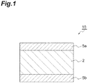
- a piezoelectric device 10 comprises a pair of electrodes 5a and 5b and a piezoelectric body 2 sandwiched between the pair of electrodes 5a and 5b. That is, an electrode 5a is laid on one surface of the piezoelectric body 2, and a different electrode 5b is laid on the other surface of the piezoelectric body 2.
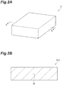
- the piezoelectric body 2 according to this embodiment is a rectangular parallelepiped. However, the shape of the piezoelectric body 2 is not limited.
- the piezoelectric body 2 is a sintered body including a piezoelectric composition.
- the piezoelectric body 2 may be a sintered body consisting of only the piezoelectric composition.
- the piezoelectric body 2 may include other ingredients in addition to the piezoelectric composition.
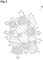
- FIG. 3 is an enlarged view of the cross section 2cs of the piezoelectric body 2 (the piezoelectric composition) illustrated in FIG. 2B .
- the piezoelectric composition constituting the piezoelectric body 2 comprises a plurality (an infinite number) of crystal particles 4.
- the crystal particles 4 are sintered with each other through grain boundaries 18 (for example, grain boundary phases).
- the crystal particle 4 has a perovskite-type crystal structure.
- the crystal particle 4 includes a core 6 and a shell 8 covering the core 6. That is, the crystal particle 4 has a core-shell structure.
- the core 6 and the shell 8 may be different crystal phases from each other.
- the core 6 and the shell 8 may have a perovskite-type crystal structure, respectively.
- the shell 8 is a phase covering a part or all of the core 6.
- One shell 8 may cover a plurality of cores 6. That is, one crystal particle 4 may include a plurality of cores 6.
- the crystal particle 4 may consist of only the core 6 and the shell 8.
- the crystal particle 4 may include other phases in adding to the core 6 and the shell 8.
- the piezoelectric composition may consist of only the crystal particles 4 including the core 6 and the shell 8.
- the piezoelectric composition may comprise other types of particles in addition to the crystal particles 4 including the core 6 and the shell 8.
- the piezoelectric composition may comprise other crystal particles that are different from the crystal particles 4 in the composition or crystal structure.
- the piezoelectric composition may comprise a particle 12 having substantially the same composition as that of the core 6 of the crystal particle 4.
- the piezoelectric composition may comprise a particle 14 having substantially the same composition as that of the shell 8 of the crystal particle 4.
- the composition of a portion of a particle 16 not having a core-shell structure may be substantially the same as that of the core 6, and the composition of other portions of the particle 16 may be substantially the same as that of the shell 8.
- the piezoelectric composition constituting the piezoelectric body 2 includes bismuth (Bi), iron (Fe), barium (Ba), titanium (Ti), and oxygen (O) as the main ingredients.
- the respective crystal particles 4 comprised in the piezoelectric composition may include bismuth, iron, barium, titanium and oxygen.
- the average value of the contents (unit: % by mass) of bismuth in the shells 8 is higher than the average value of the contents of bismuth in the cores 6. In other words, the average value of the contents of bismuth in the cores 6 is expressed as C CORE % by mass, the average value of the contents of bismuth in the shells 8 is expressed as C SHELL % by mass, and the C CORE is lower than the C SHELL .
- the C CORE % by mass may be the average value of the contents of bismuth at 10 or more measured points belonging to the cores 6 of the crystal particles 4.
- the C SHELL % by mass may be the average value of the contents of bismuth at 10 or more measured points belonging to the shells 8 of the crystal particles 4.
- the total area of the cross sections of the cores 6 exposed to the cross section 2cs of the piezoelectric body 2 (piezoelectric composition) is expressed as S CORE
- the total area of the cross sections of the shells 8 exposed to the cross section 2cs of the piezoelectric body 2 (piezoelectric composition) is expressed as S SHELL
- 100.S CORE /(S CORE + S SHELL ) is 50 to 90% by area.
- the 100.S CORE /(S CORE + S SHELL ) may be 55 to 75% by area, or 60 to 70% by area.
- the piezoelectric constant d 33 of the piezoelectric composition is higher than those of conventional bismuth ferrite -based piezoelectric compositions, and the Curie temperature Tc of the piezoelectric composition is higher than those of conventional bismuth ferrite-based piezoelectric compositions.
- the present inventors consider that the reason is as follows.
- a structure gradient region appears in the interface between the core 6 and the shell 8 to ease the mismatch of the crystal structure between the core 6 and the shell 8.
- the core 6 is a tetragonal or cubic crystal
- the shell 8 is a rhombohedral crystal
- the structure gradient region eases distortion between the core 6 and the shell 8.
- polarization reversal occurs easily similarly to morphotropic phase boundaries (namely MPB)
- the piezoelectric characteristics of the crystal particles 4 are improved, and it is easy for the piezoelectric constant d 33 of the whole piezoelectric composition to also increase.
- the cores 6 having a content of bismuth lower than that in the shells 8 it is easy for BaTiO 3 to form crystals as main phases. Consequently, although the Tc of the cores 6 themselves is lower than that of the shells 8, the dielectric constant of the cores 6 themselves is high, and therefore the d 33 of the cores 6 themselves is high. Meanwhile, in the shells 8 having a content of bismuth higher than that in the cores 6, it is easy for BiFeO 3 to form crystals as main phases. Consequently, although the d 33 of the shells 8 themselves is low, the Tc of the shells 8 is high.
- the piezoelectric constant d 33 of the piezoelectric composition is high and the Curie temperature Tc of the piezoelectric composition is high is not necessarily limited to the above reason.
- the number of all the particles comprised in the piezoelectric composition may be expressed as N, the number of the crystal particles 4 including the core 6 and the shell 8 is expressed as n, and the n/N may be 0.10 to 1.00.
- the n/N means the proportion of the number of the crystal particles 4 having both high d 33 and high Tc. As the n/N becomes high, the proportion of the number of the crystal particles 4 in that of all the particles constituting the piezoelectric composition is high, and therefore it is easy for the whole piezoelectric composition to have both high piezoelectric constant d 33 and high Curie temperature Tc.
- the n/N may be 0.20 to 1.00, 0.30 to 1.00, 0.40 to 1.00, 0.50 to 1.00, 0.60 to 1.00, 0.70 to 1.00, 0.80 to 1.00, or 0.90 to 1.0.
- the piezoelectric constant d 33 of a piezoelectric composition tends to increase.
- the C CORE /C SHELL may be 0.10 to 0.95.
- the crystal particle 4 readily has a core-shell structure. That is, when the C CORE /C SHELL is 0.10 to 0.95, it is easy for the anisotropy of the crystal structures of the core 6 and the shell 8, respectively, to increase and for a structure gradient region to appear in the interface between the core 6 and the shell 8.
- the polarization reversal of the piezoelectric composition having a crystal structure with high anisotropy is usually difficult.
- the C CORE /C SHELL may be 0.20 to 0.90, 0.30 to 0.80, or 0.50 to 0.70.
- C SHELL - C CORE (a difference between the contents of bismuth of cores 6 and shells 8) may be, for example, 2% by mass or more and 100% by mass or less.
- the C SHELL - C CORE is in the above range, it is easy for the anisotropy of the crystal structures of the core 6 and the shell 8, respectively, to increase and for a structure gradient region to appear in the interface between the core 6 and the shell 8. Consequently, it is easy for polarization reversal to occur in the crystal particle 4, for the piezoelectric characteristics of the crystal particle 4 to be improved, and for the piezoelectric constant d 33 of the piezoelectric composition to increase.
- the average composition of the whole piezoelectric composition may be represented by the chemical formula 1.
- the average composition of a plurality of crystal particles 4 comprised in the piezoelectric composition may be represented by the chemical formula 1.
- the average composition of the one crystal particle 4 in whole may be represented by the chemical formula 1.
- x[Bi m FeO 3 ] - y[Ba n TiO 3 ] (1) in the formula 1, 0.6 ⁇ x ⁇ 0.9, 0.1 ⁇ y ⁇ 0.4, x + y 1, 0.96 ⁇ m ⁇ 1.04, 0.96 ⁇ n ⁇ 1.04.
- the average composition of the whole piezoelectric composition may be represented by the chemical formula 2. That is, the piezoelectric composition represented by the chemical formula 1 may be a composite oxide represented by the chemical formula 2. That is, a part or all of the piezoelectric composition may be a solid solution of Bi m FeO 3 and Ba n TiO 3 .
- the average composition of a plurality of crystal particles 4 comprised in a piezoelectric composition may be represented by the chemical formula 2.
- the average composition of the one crystal particle 4 in whole may be represented by the chemical formula 2.
- the piezoelectric body 2 may consist of only a piezoelectric composition represented by the chemical formula 2.
- the piezoelectric body 2 may include other ingredients in addition to the piezoelectric composition represented by the chemical formula 2.
- a portion of the piezoelectric composition may be a phase consisting of Bi m FeO 3 .
- a portion of the piezoelectric composition may be a phase consisting of Ba n TiO 3 .
- the particle size of the crystal particle 4 may be, for example, 0.2 to 20 ⁇ m.
- the thickness of the shell 8 may be, for example, 0.05 to 1 ⁇ m.
- the piezoelectric composition may include elements other than the elements included in the chemical formula 1 or chemical formula 2 as impurities or additives.
- the piezoelectric composition may include an oxide of Na, Mg, Mn, Nb, V, Al, S, Zr, Si, P, K, Fe, Cu, Zn, Hf, Ta, or W.
- the total content of the respective oxides in the piezoelectric composition may be 0.3% by mass or less of the whole piezoelectric composition.
- the average composition of a whole piezoelectric composition may be analyzed, for example, by X-ray fluorescence analysis (an XRF method) or energy dispersive X-ray spectrometry (EDS).
- a core 6 and a shell 8 of a crystal particle 4 may be identified, for example, by a scanning transmission electron microscope (STEM) and EDS.
- the core 6 and the shell 8 may be identified by the contrast of images taken, for example, by STEM.
- the core 6 and the shells 8 may be identified by the difference in the content of Bi measured, for example, by EDS.
- the contents of each element in the core 6 and the shell 8,respectively, may be measured by EDS.
- the piezoelectric device 10 comprises the piezoelectric body 2 including the above piezoelectric composition, it is excellent in piezoelectric characteristics.
- the potential difference between the pair of electrodes 5a and 5b that the piezoelectric device 10 comprises may be, for example, 0.1 to 2.0 kV/mm.
- BiFeO 3 in conventional piezoelectric devices using BiFeO 3 , as long as the potential difference between the electrodes of the piezoelectric device is not a high voltage of 5.0 kV/mm or more, sufficient piezoelectric characteristics are not obtained.
- the piezoelectric device 10 according to this embodiment even though the potential difference between the electrodes 5a and 5b is a low voltage in the above numerical value range, sufficient piezoelectric characteristic is obtained.
- the piezoelectric body 2 (piezoelectric composition) to which an electric field of 0.1 to 2.0 kV/mm is applied can have a piezoelectric constant d 33 of 200 pC/N or more.
- a raw material powder (raw material particle) is first prepared.
- a formed body is formed by press-forming raw material particle.
- the formed body is sintered to obtain a sintered body.
- a piezoelectric body 2 is obtained by performing a polarization process on the sintered body. Electrodes are formed on the piezoelectric body 2 to obtain a piezoelectric device 10. Each step will be described specifically hereinafter.
- starting raw materials of a piezoelectric composition are first weighed.
- the starting raw materials may be oxides of the respective elements that constitute a piezoelectric composition represented, for example, by chemical formula (1) or compounds that become these oxides after sintering.
- the compound that is a starting raw material may be, for example, a carbonate, a hydroxide, an oxalate, a nitrate or the like.
- a specific starting raw material may be, for example, a bismuth compound, an iron compound, a barium compounds, a titanium compound, or the like.
- the molar ratio of Bi, Fe, Ba and Ti in these starting raw materials may be adjusted to the molar ratio of Bi, Fe, Ba, and Ti in the above chemical formula 1 by weighing the respective starting raw materials.
- the bismuth compound (Bi compound) may be bismuth oxide (Bi 2 O 3 ), bismuth nitrate (Bi(NO 3 ) 3 ) or the like.
- the iron compound (Fe compound) may be iron oxide (Fe 2 O 3 ), iron chloride (FeCl 3 ), iron nitrate (Fe(NO 3 ) 3 ) or the like.
- the barium compound (Ba compound) may be barium oxide (BaO), barium carbonate (BaCO 3 ), barium oxalate (C 2 BaO 4 ), barium acetate ((CH 3 COO) 2 Ba), barium nitrate (Pa(NO 3 ) 2 ), barium sulfate (BaSO 4 ), barium titanate (BaTiO 3 ) or the like.
- the titanium compound (Ti compound) may be titanium oxide (TiO 2 ) or the like.
- first raw material particles and second raw material particles two types of raw material particles (first raw material particles and second raw material particles) that are different in the content of bismuth are prepared by using the starting raw material mentioned above. All of the Bi compound, the Fe compound, the Ba compound and the Ti compound are included in at least either one of the first raw material particle and the second raw material particle.
- the content of bismuth in the first raw material particles is lower than the content of bismuth in the second raw material particles. That is, the number of moles or the mass of bismuth included in the first raw material particle is smaller than the number of moles or the mass of bismuth included in the second raw material particle.
- the first raw material particles may be prepared from at least a Ba compound and a Ti compound.
- a mixture of the above Ba compound and the above Ti compound is calcined to form a first sintered body, and first raw material particles may be obtained by pulverizing the first sintered body.
- the first raw material particles may be prepared, for example, from a Ba compound, a Ti compound, a Bi compound and a Fe compound.
- a mixture of the Ba compound, the Ti compound, the Bi compound and the Fe compound is calcined to form a first sintered body, and the first raw material particles may be obtained by pulverizing the first sintered body.
- the ratio of the number of moles of Ba to the number of moles of Ti in the first raw material particles may be n:1 similarly to a case of Ba n TiO 3 in the chemical formula 1. That is, the Ba compound and the Ti compound may be weighed respectively so that the ratio of the number of moles of Ba to the number of moles of Ti in the first raw material particles matches the composition of the perovskite-type oxide.
- the ratio of the number of moles of Bi to the number of moles of Fe in the first raw material particles may be m:1 similarly to Bi m FeO 3 in the above chemical formula 1.
- the Bi compound and the Fe compound may be weighed respectively so that the ratio of the number of moles of Bi to the number of moles of Fe in the first raw material particle matches the composition of the perovskite-type oxide.
- the first raw material particles may be a composite oxide including at least Ba and Ti (for example, Ba n TiO 3 ).
- the first raw material particles may be a composite oxide including at least Ba, Ti, Bi and Fe.
- the first raw material particles may become the core 6 of the crystal particle 4 in the piezoelectric composition after sintering.
- the second raw material particles may be prepared from at least a Bi compound and a Fe compound.
- a mixture of the above Bi compound and the above Fe compound itself (a mixture of starting raw materials) may be used as the second raw material particles without calcination.
- the above mixture of a Bi compound and a Fe compound is calcined to form a second sintered body, and second raw material particles may be obtained by pulverizing the second sintered body.
- the second raw material particles may be prepared, for example, from a Ba compound, a Ti compound, a Bi compound and a Fe compound.
- the above mixture of a Ba compound, a Ti compound, a Bi compound and a Fe compound itself may be used as the second raw material particles without calcination.
- the mixture of a Ba compound, a Ti compound, a Bi compound and a Fe compound is calcined to form a second sintered body, and second raw material particles may be obtained by pulverizing the second sintered body.
- the ratio of the number of moles of Bi to the number of moles of Fe in the second raw material particles may be m: 1 similarly to Bi m FeO 3 in the above chemical formula 1. That is, the Bi compound and the Fe compound may be weighed respectively so that the ratio of the number of moles of Bi to the number of moles of Fe in the second raw material particles matches the composition of the perovskite-type oxide.
- the ratio of the number of moles of Ba to the number of moles of Ti in the second raw material particles may be n:1 similarly to a case of Ba n TiO 3 in the above chemical formula 1. That is, the Ba compound and the Ti compound may be weighed respectively so that the ratio of the number of moles of Ba to the number of moles of Ti in the second raw material particles matches the composition of the perovskite-type oxide.
- the second raw material particles may be a composite oxide including at least Bi and Fe (for example, Bi m FeO 3 ).
- the second raw material particles may be a composite oxide including Ba, Ti, Bi, and Fe.
- the ratio of the number of moles of Bi in the second raw material particles to the number of moles of Ba in the first raw material particles may be x:y similarly to cases of the above chemical formulae 1 and 2.
- the ratio of the number of moles of Fe in the second raw material particles to the number of moles of Ti in the first raw material particles may also be x:y similarly to cases of the above chemical formulae 1 and 2.
- the C CORE /C SHELL is controlled in the range of 0.10 to 0.95 by adjusting the C1/C2.
- the C1 and the C2 can be controlled respectively by adjusting the amounts of bismuth compounds at the time of weighing the respective starting raw materials of the first raw material particles and the second raw material particles.
- the first raw material particles may be prepared from at least a Fe compound and a Ti compound.
- the first raw material particles may include elements (Fe and Ti) occupying the B site of a perovskite structure (a crystal structure represented by formula ABO 3 ) of the crystal particles 4.
- a mixture of the above Fe compound and the above Ti compound is calcined to form a first sintered body, and first raw material particles may be obtained by pulverizing the first sintered body.
- the first raw material particles may be a composite oxide including at least Fe and Ti.
- the second raw material particles may be prepared, for example, from at least a Bi compound and a Ba compound.
- the second raw material particles may include elements (Bi and Ba) occupying the A site of a perovskite structure (a crystal structure represented by a formula ABO 3 ) of the crystal particles 4.
- a mixture of the above Bi compound and the above Ba compound itself (a mixture of starting raw materials) may be used as the second raw material particles without calcination.
- a mixture of the above Bi compound and the above Ba compound is calcined to form a second sintered body, and second raw material particles may be obtained by pulverizing the second sintered body.
- the second raw material particles may be a composite oxide including at least Bi and Ba.
- the average value of the primary particle sizes of the first raw material particles may be adjusted to a desired value by pulverizing the above first sintered body.
- the primary particle sizes of the first raw material particles influence the particle sizes of the crystal particles 4 comprised in the piezoelectric composition.
- the average value of the primary particle sizes of the first raw material particles becomes large, it becomes easy for the total area S CORE of the cross sections of the cores 6 to increase, and it becomes easy for 100.S CORE /(S CORE + S SHELL ) to increase. Therefore, the 100.S CORE /(S CORE + S SHELL ) may be controlled by adjusting the average value of the primary particle sizes of the first raw material particles.
- the average value of the primary particle sizes of the second raw material particles may be adjusted to a desired value by pulverizing the above second sintered body. As the average value of the primary particle sizes of the second raw material particles becomes small, it becomes easy for the total area S CORE of the cross sections of the cores 6 to increase, and it becomes easy for the 100.S CORE /(S CORE + S SHELL ) also to increase.
- the mean particle size of the crystal particles 4 comprised in the piezoelectric composition may be controlled by adjusting the average values of the primary particle sizes of the first raw material particles and the second raw material particles.
- the average value of the primary particle sizes of the first raw material particles may be, for example, 0.1 to 20 ⁇ m.
- the average value of the primary particle sizes of the second raw material particles may be, for example, 0.01 to 3 ⁇ m. It is easy for the 100.S CORE /(S CORE + S SHELL ) to be controlled to 50 to 90 by adjusting the average values of the primary particle sizes of the first raw material particles and the second raw material particles in the above range.
- the first raw material particles and the second raw material particles may be mixed to prepare the third raw material particles.
- a mass ratio m1 becomes larger than the ratio of the second raw material particles to all the third raw material particles (for example, a mass ratio m2)
- the n/N tends to become small. That is, as m1/m2 becomes large, the number of the crystal particles 4 (particles having a core-shell structure) comprised in the piezoelectric composition tends to become small. Therefore, the n/N in the piezoelectric composition can be controlled in a desired range by adjusting the m1/m2.
- the n/N in the piezoelectric composition may be controlled in a desired range using the mixing ratio of the calcined particles having a core-shell structure (first raw material particles) to the raw material particles not having a core-shell structure (second raw material particles).
- the third raw material particles may be adjusted by covering the surface of the first raw material particles with the second raw material particles. It is easy for the crystal particles 4 having a core-shell structure to be formed by covering the surface of the first raw material particles with the second raw material particles.
- a specific method for preparing the third raw particles may be, for example, as follows. First raw material particles and a solvent are mixed to prepare a first slurry. The first raw material particles in the first slurry may be pulverized by wet mixing the first slurry by using a ball mill or the like, and the average value of the primary particle sizes of the first raw material particles may be adjusted. Meanwhile, the second raw material particles and a solvent are mixed to prepare a second slurry. The second raw material particles in the second slurry may be pulverized by wet mixing the second slurry by using the ball mill or the like, and the average value of the primary particle sizes of the second raw material particles may be adjusted.
- the solvent to use for preparing each slurries may be, for example, water, an alcohol such as ethanol, or a mixture of water and ethanol.
- the third slurry including the third raw material particles is prepared by mixing the first slurry and the second slurry by using the ball mill or the like.
- the third slurry is sprayed with a spray drier, and the dried third raw material particles are obtained.
- the third raw material particles are calcined.
- the temperature of calcination may be 700 to 1050°C.
- the calcination time may be around 1 to 3 hours. Calcination may be performed in the air atmosphere and may be performed in an oxidative atmosphere or pure oxygen.
- the wet pulverization of the third raw material particles is performed by using the ball mill or the like after the calcination.
- the pulverized third raw material particles are dried.
- a binder is added to the dried third raw material particles to obtain a formed body by press-forming the third raw material particles.
- the binder may be an organic binder such as polyvinyl alcohol or ethyl cellulose.
- a dispersing agent may be added to the binder.
- a sintered body is formed by sintering the formed body.
- a debinding treatment (the decomposition of the binder by heating) of the formed body may be performed before sintering of the formed body.
- the debinding treatment and the sintering of the formed body may be performed continuously, or may be performed separately.
- the sintering temperature may be around 1050 to 1250°C.
- the sintering time may be around 1 to 8 hours.
- the polarization process of the obtained sintered body is performed.
- the sintered body is cut into flakes and lap polishing is given to the surface of the sintered body before the polarization process.
- Cutting machines such as a cutter, a slicer or a dicing saw may be used for cutting the sintered body.
- temporary electrodes for the polarization process are formed both on a pair of the countering surfaces of the sintered body.
- An electrically conductive material constituting the temporary electrodes may be Cu, which can be removed easily by etching processing with a ferric chloride solution.
- a vacuum evaporation method or sputtering may be used for forming the temporary electrodes.
- a polarization electric field is applied between the pair of temporary electrodes sandwiching the sintered body.
- the temperature of the sintered body subjected to a polarization process may be 150 to 300°C.
- the time to apply a polarization electric field may be 1 to 30 minutes.
- the polarization electric field may be 0.9 or more times as strong as the coercive electric field of the sintered body.
- the temporary electrodes are removed from the sintered body by etching processing or the like after the polarization process.
- the sintered body is processed into a desired shape to form a piezoelectric body 2.
- a pair of electrodes 5a and 5b are formed on the surfaces of the piezoelectric body 2, and the piezoelectric body 2 is sandwiched between the electrodes 5a and 5b.
- the electrodes 5a and 5b can be formed by a vacuum evaporation method, sputtering or a plating method.
- a piezoelectric device 10 is completed through the above steps.
- the uses of the piezoelectric device 10 comprising the piezoelectric composition according to this embodiment are varied.
- the piezoelectric device 10 may be applied, for example, to an oscillator, a resonator, an actuator, a motor or a sensor.
- the specific use of the piezoelectric device may be, for example, a SAW filter, a BAW filter, a piezoelectric microphone, a head assembly, a hard disk drive and a printer head, an ink jet printer device, an ultrasonic washing machine, an ultrasonic motor, an atomizer oscillator, a fish finder, a shocking sensor, an ultrasonic diagnostic device, a waste toner sensor, a gyro sensor, a buzzer, a transformer or a lighter.
- the piezoelectric body 2 may be a thin film including the piezoelectric composition according to the present invention.
- BaCO 3 powder, TiO 2 powder, Bi 2 O 3 powder and Fe 2 O 3 powder were weighed, respectively, so that the number of moles of Ba, the number of moles of Ti, the number of moles of Bi and the number of moles of Fe became equal. That is, BaCO 3 and TiO 2 were weighed, respectively, so that the ratio of the number of moles of Ba to the number of moles of Ti satisfies the composition (BaTiO 3 ) forming a perovskite-type crystal structure.
- Bi 2 O 3 and Fe 2 O 3 were weighed, respectively, so that the ratio of the number of moles of Bi to the number of moles of Fe satisfies the composition (BaFeO 3 ) forming a perovskite-type crystal structure.
- slurry was prepared by mixing BaCO 3 , TiO 2 , Bi 2 O 3 , Fe 2 O 3 and pure water by the ball mill for 16 hours.
- the molar ratio of Ba, Ti, Bi and Fe included in the slurry was also 1:1:1:1.
- a mixed powder of BaCO 3 , TiO 2 , Bi 2 O 3 and Fe 2 O 3 was obtained by heating the slurry at 120°C and drying the slurry.
- This mixed powder was calcined at 600 to 850°C for 2 hours to obtain a calcined powder (a first raw material particle).
- First slurry was obtained by mixing the first raw material particles and pure water by the ball mill for 16 hours and pulverizing the first raw material particles.
- the average value of the primary particle sizes of the calcined powder (the first raw material particles) in the first slurry was adjusted to 1.0 ⁇ m by the above ball mill.
- a mixture of the powder of BaCO 3 , the powder of TiO 2 , the powder of Bi 2 O 3 and the powder of Fe 2 O 3 was prepared.
- the powder of BaCO 3 and the powder of TiO 2 were weighed, respectively, so that the number of moles of Ba becomes equal to the number of moles of Ti. That is, BaCO 3 and TiO 2 were weighed, respectively, so that the ratio of the number of moles of Ba to the number of moles of Ti satisfies the composition (BaTiO 3 ) forming a perovskite-type crystal structure.
- a powder of Bi 2 O 3 and a powder of Fe 2 O 3 were weighed, respectively, so that the number of moles of Bi and the number of moles of Fe become equal.
- Bi 2 O 3 and Fe 2 O 3 were weighed, respectively, so that the ratio of the number of moles of Bi to the number of moles of Fe satisfies the composition (BiFeO 3 ) forming a perovskite-type crystal structure.
- the mass of Bi included in all the second raw material particles was adjusted to a value larger than the mass of Bi included in all the first raw material particles.
- second slurry including the second raw material particles was prepared by mixing the second raw material particles and pure water by the ball mill for 16 hours.
- the average value of the primary particle sizes of the second raw material particles in the second slurry was adjusted to 0.1 ⁇ m by the above ball mill.
- the mass of Bi included in all the second slurry was larger than the mass of Bi included in all the first slurry.
- Third slurry was prepared by mixing the first slurry and the second slurry by using the ball mill.
- Third raw material particles composed of the first raw material particles and the second raw material particles covering the first raw material particles were obtained by spraying the third slurry with a spray drier.
- the third raw material particles were calcined at 700°C for 2 hours.
- the calcination of the third raw material particles was performed in the air atmosphere.
- the wet pulverization of the third raw material particles was performed by using the ball mill.
- the third raw material particles were dried and mixed with a binder.
- a formed body was formed from the mixture of the third raw material particles and the binder.
- the formed body was sintered at 1000°C.
- the sintering of the formed body was performed in the air atmosphere.
- the sintering time of the formed body was 4 hours.
- a sintered body composed of a piezoelectric composition in Example 1 was obtained through the above steps.
- the cross section of the sintered body of Comparative Example 2 was irradiated with a gallium ion beam, and a flaky sample of Comparative Example 2 was produced.
- the photograph of the cross section of the sample of Comparative Example 2 was taken by a STEM.
- a JEM-2100F manufactured by JEOL Ltd. was used as a STEM.
- the cross section of the sintered body of Comparative Example 2 is illustrated in FIG. 4 .
- crystal particles having a core-shell structure were not found.
- Example 1 In the same method as the case of Comparative Example 2, the sample (flaky sintered body) of Example 1 was produced.
- the photograph of the cross section of the sintered body of Example 1 was taken by the STEM.
- the cross sections of the sintered body of Example 1 is illustrated in FIG. 5A and FIG. 5B .
- the cross section illustrated in FIG. 5B is the same as the cross section illustrated in FIG. 5A .
- the compositions of a plurality of measured points 1 to 12 illustrated in FIG. 5B (respective points to which X marks are appended) were analyzed by an STEM-EDS.
- results of the analysis based on the STEM and an EDS it was confirmed that the sintered body of Example 1 is a composite oxide including bismuth, iron, barium and titanium.
- a plurality of crystal particles in the cross section of the sintered body of Example 1 are also the above composite oxide. It has also been confirmed that the plurality of crystal particles in the cross section of the sintered body of Example 1 are composed of a core and a shell covering the core and the contents of Bi in the cores are lower than the contents of Bi in the shells.
- Measured points 1 to 6 illustrated in FIG. 5B belong to the shell of either of two crystal particles, and are located near a grain boundary between the two crystal particles (near the interface between two shells).
- Measured points 7, 8 and 9 illustrated in FIG. 5B belong to the core of crystal particles.
- measured points 10 to 12 illustrated in FIG. 5B belong to the core of the other crystal particles.
- the contents of elements at the respective measured points 1 to 6 belonging to shells are illustrated in Table 1 below.
- the average values of the contents of elements at the respective measured points 1 to 6 are illustrated in Table 1 below.
- the contents of elements at the respective measured points 7 to 12 belonging to the cores are illustrated in the following Table 2.
- the average values of the contents of elements at the respective measured points 7 to 12 are illustrated in the following Table 2.
- the unit of the contents of the elements illustrated in Tables 1 and 2 below is % by mass.
- the contents of Bi in the cores of the crystal particles were lower than the contents of Bi in the shells of the crystal particles. Crystal particles composed of a core and a shell covering the core will be described as "core-shell particles" hereinafter.
- Table 1 Table 1 Contents (% by mass) of Elements in Shells Measured point Ti Fe Ba Bi 1 5.32 23.14 5.01 33.42 2 5.02 23.88 6.07 34.21 3 5.46 24 5.16 33.45 4 4.46 23.96 6.59 33.83 5 4.1 23.18 5.86 34.01 6 4.81 24.24 5.65 33.6 Average 4.9 23.7 5.7 33.8
- Table 2 Contents (% by mass) of Elements in Cores Measured point Ti Fe Ba Bi 7 6.33 20.47 6.74 30.35 8 5.08 20.71 7.96 30.13 9 7.21 20.52 7.77 29.61 10 6.96 21.22 6.76 30.39 11 6.31 21.42 7.06 30.06 12 5.09 20.41 7.25 29.78 Average 6.2 20.8 7.3 30.1
- a plurality of areas belonging to the cross section of the sintered body of Example 1 were observed by the STEM, and the cross sections of 100 core-shell particles exposed to the cross section of the sintered body were selected at random.
- the size of the visual fields of the respective observed areas was 5 ⁇ m ⁇ 5 ⁇ m.
- the images of the cross sections of the respective core-shell particles were analyzed by the elemental mapping of the cross sections of the respective core-shell particles based on the STEM-EDS.
- the area S1 of the cross sections of the cores of each core-shell particle was measured by image analysis.
- the area S1 was calculated by counting the number of pixels that cores occupied in the image of the cross section of the core-shell particle.
- the area S2 of the cross section of the shell of each core-shell particle was measured by the same method.
- the total value of the S1s of 100 core-shell particles is considered as the S CORE of Example 1.
- the total value of the S2s of 100 core-shell particles is considered as the S SHELL of Example 1.
- 100.S CORE /(S CORE + S SHELL ) of Example 1 was a value illustrated in Table 3 below. "S" described in Tables 3 and 4 below means 100.S CORE /(S CORE + S SHELL ).
- the piezoelectric constant d 33 (unit: pC/N) of the sintered body (piezoelectric composition) of Example 1 was measured by using a d 33 meter.
- the d 33 meter is a device for measuring d 33 s by the Berlincourt method based on JIS (Japanese Industrial Standards) R 1696. In the Berlincourt method, the d 33 is measured by utilizing a piezoelectric positive effect at the time when vibration is given to a piezoelectric composition.
- d 33 in Example 1 was a value illustrated in Table 3 below. It is preferable that d 33 is 200 pC/N or more.
- the sintered body (piezoelectric composition) of Example 1 was processed with a double-sided lapping machine, and the thickness of the sintered body was adjusted to 0.4 mm. Then, the sintered body was cut with the dicing saw and the size of the sintered body was adjusted to 6 mm in length ⁇ 6 mm in width. A pair of silver electrodes was formed on both end faces of the sintered body after cutting. The size of the respective silver electrodes was 5 mm in length ⁇ 5 mm in width.
- the sintered body on which the silver electrodes were formed was placed in an electric furnace. A temperature T1 at the time when the electrostatic capacity of the sintered body in the electric furnace became the maximum value in a temperature rise process was measured.
- a temperature T2 at the time when the electrostatic capacity of the sintered body became the maximum value in a temperature drop process following the temperature rise process was measured.
- An LCR meter was used for measuring T1 and T2.
- the average value of the T1 and the T2 was considered as the Curie temperature Tc of the sintered body (piezoelectric composition) of Example 1.
- the Tc of Example 1 was a value illustrated in Table 3 below. In order that the piezoelectric composition maintains desired piezoelectricity also at high temperatures, it is preferable that the Tc is 250°C or more.
- Example 2 the average value of the primary particle sizes of the first raw material particles included in the first slurry was increased as compared to that of the case of Example 1.
- a sintered body (piezoelectric composition) of Example 2 was produced by the same method as in Example 1 except for this matter.
- Example 3 the average value of the primary particle sizes of the first raw material particles included in the first slurry was increased as compared to that of the case of Example 2.
- a sintered body (piezoelectric composition) of Example 3 was produced by the same method as in Example 1 except for this matter.
- Example 4 the average value of the primary particle sizes of the first raw material particles included in the first slurry was increased as compared to that of the case of Example 3.
- a sintered body (piezoelectric composition) of Example 4 was produced by the same method as in Example 1 except for this matter.
- Example 5 the average value of the primary particle sizes of the first raw material particles included in the first slurry was increased as compared to that of the case of Example 4.
- a sintered body (piezoelectric composition) of Example 5 was produced by the same method as in Example 1 except for this matter.
- Example 6 the average value of the primary particle sizes of the first raw material particles included in the first slurry was increased as compared to that of the case of Example 5.
- a sintered body (piezoelectric composition) of Example 6 was produced by the same method as in Example 1 except for this matter.
- Example 7 the average value of the primary particle sizes of the first raw material particles included in the first slurry was increased as compared to that of the case of Example 6.
- a sintered body (piezoelectric composition) of Example 7 was produced by the same method as in Example 1 except for this matter.
- Example 8 the average value of the primary particle sizes of the first raw material particles included in the first slurry was increased as compared to that of the case of Example 7.
- a sintered body (piezoelectric composition) of Example 8 was produced by the same method as in Example 1 except for this matter.
- Example 9 the average value of the primary particle sizes of the first raw material particles included in the first slurry was increased as compared to that of the case of Example 8.
- a sintered body (piezoelectric composition) of Example 9 was produced by the same method as in Example 1 except for this matter.
- Comparative Example 1 the average value of the primary particle sizes of the first raw material particles included in the first slurry was increased as compared to that of the case of Example 9.
- a sintered body (piezoelectric composition) of Comparative Example 1 was produced by the same method as in Example 1 except for this matter.
- Comparative Example 2 As described above, in Comparative Example 2, the second slurry and the third slurry were not prepared, and the first slurry was used instead of the third slurry.
- a sintered body (piezoelectric composition) of Comparative Example 2 was produced by the same method as in Example 1 except for this matter.
- Comparative Example 3 the average value of the primary particle sizes of the first raw material particles included in the first slurry was decreased as compared to that of the case of Example 1.
- a sintered body (piezoelectric composition) of Comparative Example 3 was produced by the same method as in Example 1 except for this matter.
- Comparative Example 4 the average value of the primary particle sizes of the first raw material particles included in the first slurry was decreased as compared to that of the case of Comparative Example 3.
- a sintered body (piezoelectric composition) of Comparative Example 4 was produced by the same method as in Example 1 except for this matter.
- Comparative Example 5 the average value of the primary particle sizes of the first raw material particles included in the first slurry was decreased as compared to that of the case of Comparative Example 4.
- a sintered body (piezoelectric composition) of Comparative Example 5 was produced by the same method as in Example 1 except for this matter.
- Comparative Example 6 the average value of the primary particle sizes of the first raw material particles included in the first slurry was decreased as compared to that of the case of Comparative Example 5.
- a sintered body (piezoelectric composition) of Comparative Example 6 was produced by the same method as in Example 1 except for this matter.
- Comparative Example 7 the average value of the primary particle sizes of the first raw material particles included in the first slurry was decreased as compared to that of the case of Comparative Example 6.
- a sintered body (piezoelectric composition) of Comparative Example 7 was produced by the same method as in Example 1 except for this matter.
- Comparative Example 8 the first slurry and the third slurry were not prepared, and the second slurry was used instead of the third slurry.
- a sintered body (piezoelectric composition) of Comparative Example 8 was produced by the same method as in Example 1 except for this matter.
- the sintered bodies in Examples 2 to 9 and Comparative Examples 1 to 8 were analyzed, respectively, by the same method as in Example 1. It was confirmed that all of the sintered bodies of Examples 2 to 9 and Comparative Examples 1, 3 to 7 are composite oxides including bismuth, iron, barium and titanium similarly to Example 1. It was confirmed that all of the sintered bodies of Examples 2 to 9 and Comparative Examples 1, 3 to 7 comprised a plurality of core-shell particles similarly to Example 1. Meanwhile, the existence of core-shell particles could not be confirmed in the cross sections of the sintered bodies of Comparative Examples 2 and 8.
- the respective 100.S CORE /(S CORE + S SHELL )s in Examples 2 to 9 and Comparative Examples 1, 3 to 7 were values illustrated in Table 3 below. In both cases of Comparative Examples 2 and 8, Bi was dispersed nearly homogeneously all over the crystal particles comprised in the sintered bodies, and there was no difference between the contents of Bi inside the crystal particles and near the grain boundaries.
- the d 33 s of the respective sintered bodies of Examples 2 to 9 and Comparative Examples 1 to 8 were measured by the same method as in Example 1.
- the d 33 s of the respective sintered bodies of Examples 2 to 9 and Comparative Examples 1 to 8 were values illustrated in Table 3 below.
- the Tcs of the respective sintered bodies of Examples 2 to 9 and Comparative Examples 1 to 8 were measured by the same method as in Example 1.
- the Tcs of the respective sintered bodies in Examples 2 to 9 and Comparative Examples 1 to 8 were values illustrated in Table 3 below.
- the d 33 s were 200 pC/N or more, and the Tcs were 250°C or more. Meanwhile, there were no Comparative Examples, the d 33 s of which were 200 pC/N or more and the Tcs of which were 250°C or more.
- Example 10 When the mass of the second raw material particles included in the second slurry was expressed as M2 and the mass of the first raw material particles included in the first slurry was expressed as M1, in Example 10, M1/M2 was adjusted to a value smaller than that of the case of Example 4.
- a sintered body (piezoelectric composition) of Example 10 was produced by the same method as Example 4 except for this matter.
- the first raw material particles of Examples 10 to 18 and the primary particle size thereof were the same as the first raw material particles of Example 4 and the primary particle size thereof, respectively.
- the second raw material particles of Examples 10 to 18 and the primary particle size thereof were the same as the second raw material particles of Example 4 and the primary particle size thereof, respectively.
- Example 11 the M1/M2 was adjusted to a value smaller than that of the case of Example 4.
- a sintered body (piezoelectric composition) of Example 11 was produced by the same method as Example 4 except for this matter.
- Example 12 the M1/M2 was adjusted to a value smaller than that of the case of Example 4.
- a sintered body (piezoelectric composition) of Example 12 was produced by the same method as Example 4 except for this matter.
- Example 13 the M1/M2 was adjusted to a value smaller than that of the case of Example 4.
- a sintered body (piezoelectric composition) of Example 13 was produced by the same method as Example 4 except for this matter.
- Example 14 the M1/M2 was adjusted to a value smaller than that of the case of Example 4.
- a sintered body (piezoelectric composition) and a piezoelectric device of Example 14 were produced by the same method as Example 4 except for this matter.
- Example 15 the M1/M2 was adjusted to a value smaller than that of the case of Example 4.
- a sintered body (piezoelectric composition) of Example 15 was produced by the same method as Example 4 except for this matter.
- Example 16 the M1/M2 was adjusted to a value smaller than that of the case of Example 4.
- a sintered body (piezoelectric composition) of Example 16 was produced by the same method as Example 4 except for this matter.
- Example 17 the M1/M2 was adjusted to a value smaller than that of the case of Example 4.
- a sintered body (piezoelectric composition) of Example 17 was produced by the same method as Example 4 except for this matter.
- Example 18 the M1/M2 was adjusted to a value smaller than that of the case of Example 4.
- a sintered body (piezoelectric composition) of Example 18 was produced by the same method as Example 4 except for this matter.
- the sintered bodies of Examples 10 to 18 were analyzed by the same method as in Example 1. It was confirmed that all of the sintered bodies of Examples 10 to 18 are composite oxides including bismuth, iron, barium and titanium similarly to Example 1. It was confirmed that all of the sintered bodies of Examples 10 to 18 comprise a plurality of core-shell particles similarly to Example 1.
- the 100.S CORE /(S CORE + S SHELL )s in Examples 10 to 18 were values illustrated in Table 4 below.
- Example 10 Five points belonging to the cross section of the sintered body of Example 10 were analyzed by the STEM and the STEM-EDS similarly to the case of Example 1. The number of all the particles existing in each visual field was counted, and the total value N of the number of all the particles existing in all the visual field was calculated. "All the particles" include core-shell particles, and also include crystal particles not having a core-shell structure. The number of core-shell particles existing in each visual field was counted, and the total value n of the number of core-shell particles existing in all the visual field was calculated. The size of visual fields of analyzed points was 5 ⁇ m ⁇ 5 ⁇ m. The n/N in Example 10 was calculated from the n and the N. The n/N in Example 10 was a value illustrated in Table 4 below. The n/Ns in Examples 11 to 18 were calculated by the same method as the case of Example 10. The n/Ns in Examples 10 to 18 were values illustrated in Table 4 below.
- the d 33 s of the sintered bodies of Examples 10 to 18 were measured by the same method as in Example 1.
- the d 33 s of the sintered bodies of Examples 10 to 18 were values illustrated in Table 4 below.
- the Tcs of the sintered bodies of Examples 10 to 18 were measured by the same method as in Example 1.
- the Tcs of the sintered bodies of Examples 10 to 18 were values illustrated in Table 4 below.
- the d 33 s were 200 pC/N or more, and the Tcs were 250°C or more.
- Example 3 [Table 3] Table 3 S [%] d 33 [pC/N] Tc [°C] Comparative Example 8 - 104 589 Comparative Example 7 10 113 563 Comparative Example 6 20 139 502 Comparative Example 5 30 145 484 Comparative Example 4 40 163 466 Comparative Example 3 45 189 458 Example 1 50 210 422 Example 2 55 223 405 Example 3 60 231 378 Example 4 65 235 361 Example 5 70 230 356 Example 6 75 225 330 Example 7 80 222 301 Example 8 85 221 288 Example 9 90 223 261 Comparative Example 1 95 217 239 Comparative Example 2 - 220 180 [Table 4] Table 4 S [%] n/N d 33 [pC/N] Tc [°C] Example 4 65 0.10 235 361 Example 10 65 0.20 237 354 Example 11 65 0.30 238 338 Example 12 65 0.40 240 321 Example 13 65 0.50 241 344 Example 14 65 0.60 248 358 Example 15 65 0.70 250 331
- a piezoelectric composition the piezoelectric constant d 33 of which is high and the Curie temperature Tc of which is high, and a piezoelectric device comprising the piezoelectric composition are provided.
Landscapes
- Chemical & Material Sciences (AREA)
- Engineering & Computer Science (AREA)
- Ceramic Engineering (AREA)
- Manufacturing & Machinery (AREA)
- Organic Chemistry (AREA)
- Materials Engineering (AREA)
- Structural Engineering (AREA)
- Inorganic Chemistry (AREA)
- Life Sciences & Earth Sciences (AREA)
- Environmental & Geological Engineering (AREA)
- General Life Sciences & Earth Sciences (AREA)
- Geology (AREA)
- Composite Materials (AREA)
- Compositions Of Oxide Ceramics (AREA)
Abstract
Description
- The present invention relates to a piezoelectric composition and a piezoelectric device.
- A perovskite-type metal oxide is known as a common piezoelectric composition. The composition of a perovskite-type metal oxide is represented by ABO3. A perovskite-type piezoelectric composition is, for example, lead zirconate titanate (Pb(Zr,Ti)O3). The Curie temperature (Tc) of lead zirconate titanate (PZT) is high, and the piezoelectric constant (d33) of PZT is high. However, PZT is harmful to the environment or the human body because it includes lead as an element in the A site. The piezoelectric composition not including lead is required in view of influence on the environment or the human body.
- A specific example of a piezoelectric composition not using lead is bismuth ferrite (BiFeO3) described in the following Non Patent Literature 1. The Tc of bismuth ferrite (BFO) is high, and BFO exhibits large spontaneous polarization. However, with BFO alone, the anisotropy is high and the leakage current is large, so sufficient piezoelectric performance (for example, piezoelectric constant d33) is not obtained.
- Therefore, a piezoelectric composition where the Tc is high and the d33 is high is required. A binary compound composed of barium titanate and bismuth ferrite is disclosed in the following
Non Patent Literature 2. A ternary compound composed of barium titanate, bismuth ferrite and bismuth magnesate titanate is disclosed in Japanese Unexamined Patent Publication No.2013-191751 2013-95627 - [Non Patent Literature 1] Tadej Rojac et al., "Strong ferroelectric domain-wall pinning in BiFeO3 ceramics", JOURNAL OF APPLIED PHYSICS, 108, 074107, 2010.
[Non Patent Literature 2] Zhenyong Cen et al., "Effect of sintering temperature on microstructure and piezoelectric properties of Pb-free BiFeO3-BaTiO3 ceramics in the composition range of large BiFeO3 concentrations", J Electroceram, 31, p. 15-20, 2013. - A piezoelectric composition described in Japanese Unexamined Patent Publication
2013-191751 2013-191751 Non Patent Literature 2, the d33 of the piezoelectric composition after a polarization process is around 130 pC/N, which is small. A bismuth ferrite-based piezoelectric composition produced by a method described in Japanese Unexamined Patent Publication No.2013-95627 - The present invention has been completed in view of the above circumstances, and an object of the present invention is to provide a piezoelectric composition where the piezoelectric constant d33 is high and the Curie temperature Tc is high, and a piezoelectric device using the piezoelectric composition.
- The piezoelectric composition according to one aspect of the present invention is a piezoelectric composition comprising a plurality of crystal particles, wherein the piezoelectric composition includes bismuth, iron, barium, titanium and oxygen; the crystal particle includes a core and a shell having a content of bismuth higher than that in the core and covering the core; and the total area of the cross sections of the cores exposed to the cross section of the piezoelectric composition is expressed as SCORE, the total area of the cross sections of the shells exposed to the cross section of the piezoelectric composition is expressed as SSHELL, and 100.SCORE/(SCORE + SSHELL) is 50 to 90.
- In one aspect of the present invention, the number of all the particles comprised in the piezoelectric composition may be expressed as N, the number of the crystal particles including the cores and the shells may be expressed as n, and n/N may be 0.10 to 1.00.
- A piezoelectric composition according to one aspect of the present invention may be a sintered body.
- A piezoelectric device according to one aspect of the present invention comprises the above piezoelectric composition.
- In one aspect of the present invention, the piezoelectric constant d33 of a piezoelectric composition to which an electric field of 0.1 to 2.0 kV/mm is applied may be 200 pC/N or more.
- According to the present invention, a piezoelectric composition where the piezoelectric constant d33 is high and the Curie temperature Tc is high, and a piezoelectric device using the piezoelectric composition are provided.
-
-
FIG. 1 is a sectional view of a piezoelectric device comprising a piezoelectric composition (piezoelectric body) according to one embodiment of the present invention; -
FIG. 2A is a typical perspective view of the piezoelectric composition (piezoelectric body) illustrated inFIG. 1 , andFIG. 2B is a sectional view of the piezoelectric composition (piezoelectric body) illustrated inFIG. 2A (viewed along line b-b); -
FIG. 3 is an enlarged view of the cross section of the piezoelectric composition (piezoelectric body) illustrated inFIG. 2B and is a sectional view of a plurality of crystal particles including a core and a shell; -
FIG. 4 is a photograph of a portion of the cross section of a piezoelectric composition (sintered body) of Comparative Example 2; and -
FIG. 5A is a photograph of a portion of the cross section of a piezoelectric composition (sintered body) in Example 1, andFIG. 5B illustrates points at which the composition was analyzed in the cross section of the piezoelectric composition (sintered body) illustrated inFIG. 5A . - Preferable embodiments of the present invention will be described in detail hereinafter referring to the drawings appropriately. In the drawings, the same or equivalent components are indicated with the same signs. The present invention is not limited to the following embodiments.
- As shown in
FIG. 1 , apiezoelectric device 10 according to this embodiment comprises a pair ofelectrodes piezoelectric body 2 sandwiched between the pair ofelectrodes electrode 5a is laid on one surface of thepiezoelectric body 2, and adifferent electrode 5b is laid on the other surface of thepiezoelectric body 2. As illustrated inFIG. 2A , thepiezoelectric body 2 according to this embodiment is a rectangular parallelepiped. However, the shape of thepiezoelectric body 2 is not limited. - The
piezoelectric body 2 is a sintered body including a piezoelectric composition. Thepiezoelectric body 2 may be a sintered body consisting of only the piezoelectric composition. Thepiezoelectric body 2 may include other ingredients in addition to the piezoelectric composition. -
FIG. 3 is an enlarged view of the cross section 2cs of the piezoelectric body 2 (the piezoelectric composition) illustrated inFIG. 2B . As illustrated inFIG. 3 , the piezoelectric composition constituting thepiezoelectric body 2 comprises a plurality (an infinite number) ofcrystal particles 4. Thecrystal particles 4 are sintered with each other through grain boundaries 18 (for example, grain boundary phases). Thecrystal particle 4 has a perovskite-type crystal structure. Thecrystal particle 4 includes acore 6 and ashell 8 covering thecore 6. That is, thecrystal particle 4 has a core-shell structure. Thecore 6 and theshell 8 may be different crystal phases from each other. Thecore 6 and theshell 8 may have a perovskite-type crystal structure, respectively. Theshell 8 is a phase covering a part or all of thecore 6. Oneshell 8 may cover a plurality ofcores 6. That is, onecrystal particle 4 may include a plurality ofcores 6. Thecrystal particle 4 may consist of only thecore 6 and theshell 8. Thecrystal particle 4 may include other phases in adding to thecore 6 and theshell 8. The piezoelectric composition may consist of only thecrystal particles 4 including thecore 6 and theshell 8. The piezoelectric composition may comprise other types of particles in addition to thecrystal particles 4 including thecore 6 and theshell 8. For example, the piezoelectric composition may comprise other crystal particles that are different from thecrystal particles 4 in the composition or crystal structure. For example, the piezoelectric composition may comprise aparticle 12 having substantially the same composition as that of thecore 6 of thecrystal particle 4. The piezoelectric composition may comprise aparticle 14 having substantially the same composition as that of theshell 8 of thecrystal particle 4. The composition of a portion of aparticle 16 not having a core-shell structure may be substantially the same as that of thecore 6, and the composition of other portions of theparticle 16 may be substantially the same as that of theshell 8. - The piezoelectric composition constituting the
piezoelectric body 2 includes bismuth (Bi), iron (Fe), barium (Ba), titanium (Ti), and oxygen (O) as the main ingredients. Therespective crystal particles 4 comprised in the piezoelectric composition may include bismuth, iron, barium, titanium and oxygen. The average value of the contents (unit: % by mass) of bismuth in theshells 8 is higher than the average value of the contents of bismuth in thecores 6. In other words, the average value of the contents of bismuth in thecores 6 is expressed as CCORE% by mass, the average value of the contents of bismuth in theshells 8 is expressed as CSHELL% by mass, and the CCORE is lower than the CSHELL. The CCORE% by mass may be the average value of the contents of bismuth at 10 or more measured points belonging to thecores 6 of thecrystal particles 4. The CSHELL% by mass may be the average value of the contents of bismuth at 10 or more measured points belonging to theshells 8 of thecrystal particles 4. The total area of the cross sections of thecores 6 exposed to the cross section 2cs of the piezoelectric body 2 (piezoelectric composition) is expressed as SCORE, the total area of the cross sections of theshells 8 exposed to the cross section 2cs of the piezoelectric body 2 (piezoelectric composition) is expressed as SSHELL, and 100.SCORE/(SCORE + SSHELL) is 50 to 90% by area. The 100.SCORE/(SCORE + SSHELL) may be 55 to 75% by area, or 60 to 70% by area. - Since the 100.SCORE/(SCORE + SSHELL) is 50 to 90 in this embodiment, the piezoelectric constant d33 of the piezoelectric composition is higher than those of conventional bismuth ferrite -based piezoelectric compositions, and the Curie temperature Tc of the piezoelectric composition is higher than those of conventional bismuth ferrite-based piezoelectric compositions. The present inventors consider that the reason is as follows.
- When a
crystal particle 4 includes acore 6 and ashell 8 that are different in the composition and crystal structure, a structure gradient region appears in the interface between thecore 6 and theshell 8 to ease the mismatch of the crystal structure between thecore 6 and theshell 8. For example, thecore 6 is a tetragonal or cubic crystal, theshell 8 is a rhombohedral crystal, and the structure gradient region eases distortion between thecore 6 and theshell 8. Incrystal particles 4 having a structure gradient region, since polarization reversal occurs easily similarly to morphotropic phase boundaries (namely MPB), the piezoelectric characteristics of thecrystal particles 4 are improved, and it is easy for the piezoelectric constant d33 of the whole piezoelectric composition to also increase. In thecores 6 having a content of bismuth lower than that in theshells 8, it is easy for BaTiO3 to form crystals as main phases. Consequently, although the Tc of thecores 6 themselves is lower than that of theshells 8, the dielectric constant of thecores 6 themselves is high, and therefore the d33 of thecores 6 themselves is high. Meanwhile, in theshells 8 having a content of bismuth higher than that in thecores 6, it is easy for BiFeO3 to form crystals as main phases. Consequently, although the d33 of theshells 8 themselves is low, the Tc of theshells 8 is high. Since the 100.SCORE/(SCORE + SSHELL) is 50 to 90, the high d33 of thecores 6 themselves and the high Tc of theshells 8 are compatible, and the whole piezoelectric composition has both high piezoelectric constant d33 and high Curie temperature Tc. When the 100.SCORE/(SCORE + SSHELL) is out of the range of 50 to 90, either the d33 or the Tc decreases markedly, and therefore the compatibility of the d33 with the Tc is difficult. However, the reason why the piezoelectric constant d33 of the piezoelectric composition is high and the Curie temperature Tc of the piezoelectric composition is high is not necessarily limited to the above reason. - The number of all the particles comprised in the piezoelectric composition may be expressed as N, the number of the
crystal particles 4 including thecore 6 and theshell 8 is expressed as n, and the n/N may be 0.10 to 1.00. The n/N means the proportion of the number of thecrystal particles 4 having both high d33 and high Tc. As the n/N becomes high, the proportion of the number of thecrystal particles 4 in that of all the particles constituting the piezoelectric composition is high, and therefore it is easy for the whole piezoelectric composition to have both high piezoelectric constant d33 and high Curie temperature Tc. For the same reason, the n/N may be 0.20 to 1.00, 0.30 to 1.00, 0.40 to 1.00, 0.50 to 1.00, 0.60 to 1.00, 0.70 to 1.00, 0.80 to 1.00, or 0.90 to 1.0. With an increase in the n/N, the piezoelectric constant d33 of a piezoelectric composition tends to increase. - The CCORE/CSHELL may be 0.10 to 0.95. When the CCORE/CSHELL is 0.10 to 0.95, the
crystal particle 4 readily has a core-shell structure. That is, when the CCORE/CSHELL is 0.10 to 0.95, it is easy for the anisotropy of the crystal structures of thecore 6 and theshell 8, respectively, to increase and for a structure gradient region to appear in the interface between thecore 6 and theshell 8. The polarization reversal of the piezoelectric composition having a crystal structure with high anisotropy is usually difficult. Meanwhile, since it is easy for polarization reversal to occur in acrystal particle 4 having a structure gradient region, it is easy for the piezoelectric characteristics of thecrystal particle 4 to be improved, and for the piezoelectric constant d33 of the piezoelectric composition to increase. For the same reason, the CCORE/CSHELL may be 0.20 to 0.90, 0.30 to 0.80, or 0.50 to 0.70. - CSHELL - CCORE (a difference between the contents of bismuth of
cores 6 and shells 8) may be, for example, 2% by mass or more and 100% by mass or less. When the CSHELL - CCORE is in the above range, it is easy for the anisotropy of the crystal structures of thecore 6 and theshell 8, respectively, to increase and for a structure gradient region to appear in the interface between thecore 6 and theshell 8. Consequently, it is easy for polarization reversal to occur in thecrystal particle 4, for the piezoelectric characteristics of thecrystal particle 4 to be improved, and for the piezoelectric constant d33 of the piezoelectric composition to increase. - The average composition of the whole piezoelectric composition may be represented by the chemical formula 1. The average composition of a plurality of
crystal particles 4 comprised in the piezoelectric composition may be represented by the chemical formula 1. The average composition of the onecrystal particle 4 in whole may be represented by the chemical formula 1.
x[BimFeO3] - y[BanTiO3] (1)
in the formula 1, 0.6 ≤ x ≤ 0.9, 0.1 ≤ y ≤ 0.4, x + y = 1, 0.96 ≤ m ≤ 1.04, 0.96 ≤ n ≤ 1.04. - The average composition of the whole piezoelectric composition may be represented by the
chemical formula 2. That is, the piezoelectric composition represented by the chemical formula 1 may be a composite oxide represented by thechemical formula 2. That is, a part or all of the piezoelectric composition may be a solid solution of BimFeO3 and BanTiO3. The average composition of a plurality ofcrystal particles 4 comprised in a piezoelectric composition may be represented by thechemical formula 2. The average composition of the onecrystal particle 4 in whole may be represented by thechemical formula 2. Thepiezoelectric body 2 may consist of only a piezoelectric composition represented by thechemical formula 2. Thepiezoelectric body 2 may include other ingredients in addition to the piezoelectric composition represented by thechemical formula 2.
(BixmBayn)(FexTiy)O3 (2)
in theformula 2, 0.6 ≤ x ≤ 0.9, 0.1 ≤ y ≤ 0.4, x + y = 1, 0.96 ≤ m ≤ 1.04, 0.96 ≤ n ≤ 1.04. - A portion of the piezoelectric composition may be a phase consisting of BimFeO3. A portion of the piezoelectric composition may be a phase consisting of BanTiO3.
- The particle size of the
crystal particle 4 may be, for example, 0.2 to 20 µm. The thickness of theshell 8 may be, for example, 0.05 to 1 µm. - The piezoelectric composition may include elements other than the elements included in the chemical formula 1 or
chemical formula 2 as impurities or additives. For example, the piezoelectric composition may include an oxide of Na, Mg, Mn, Nb, V, Al, S, Zr, Si, P, K, Fe, Cu, Zn, Hf, Ta, or W. When the piezoelectric composition includes these oxides and the like, the total content of the respective oxides in the piezoelectric composition may be 0.3% by mass or less of the whole piezoelectric composition. - The average composition of a whole piezoelectric composition may be analyzed, for example, by X-ray fluorescence analysis (an XRF method) or energy dispersive X-ray spectrometry (EDS). A
core 6 and ashell 8 of acrystal particle 4 may be identified, for example, by a scanning transmission electron microscope (STEM) and EDS. Thecore 6 and theshell 8 may be identified by the contrast of images taken, for example, by STEM. Thecore 6 and theshells 8 may be identified by the difference in the content of Bi measured, for example, by EDS. The contents of each element in thecore 6 and theshell 8,respectively, may be measured by EDS. - Since the
piezoelectric device 10 comprises thepiezoelectric body 2 including the above piezoelectric composition, it is excellent in piezoelectric characteristics. The potential difference between the pair ofelectrodes piezoelectric device 10 comprises may be, for example, 0.1 to 2.0 kV/mm. In conventional piezoelectric devices using BiFeO3, as long as the potential difference between the electrodes of the piezoelectric device is not a high voltage of 5.0 kV/mm or more, sufficient piezoelectric characteristics are not obtained. Meanwhile, in thepiezoelectric device 10 according to this embodiment, even though the potential difference between theelectrodes - Next, an example of a method for manufacturing the piezoelectric composition and a
piezoelectric device 10 according to this embodiment will be described. In the manufacturing of a piezoelectric composition, a raw material powder (raw material particle) is first prepared. A formed body is formed by press-forming raw material particle. The formed body is sintered to obtain a sintered body. Then, apiezoelectric body 2 is obtained by performing a polarization process on the sintered body. Electrodes are formed on thepiezoelectric body 2 to obtain apiezoelectric device 10. Each step will be described specifically hereinafter. - In a granulating step, starting raw materials of a piezoelectric composition are first weighed. The starting raw materials may be oxides of the respective elements that constitute a piezoelectric composition represented, for example, by chemical formula (1) or compounds that become these oxides after sintering. The compound that is a starting raw material may be, for example, a carbonate, a hydroxide, an oxalate, a nitrate or the like. A specific starting raw material may be, for example, a bismuth compound, an iron compound, a barium compounds, a titanium compound, or the like. The molar ratio of Bi, Fe, Ba and Ti in these starting raw materials may be adjusted to the molar ratio of Bi, Fe, Ba, and Ti in the above chemical formula 1 by weighing the respective starting raw materials.
- The bismuth compound (Bi compound) may be bismuth oxide (Bi2O3), bismuth nitrate (Bi(NO3)3) or the like. The iron compound (Fe compound) may be iron oxide (Fe2O3), iron chloride (FeCl3), iron nitrate (Fe(NO3)3) or the like. The barium compound (Ba compound) may be barium oxide (BaO), barium carbonate (BaCO3), barium oxalate (C2BaO4), barium acetate ((CH3COO)2Ba), barium nitrate (Pa(NO3)2), barium sulfate (BaSO4), barium titanate (BaTiO3) or the like. The titanium compound (Ti compound) may be titanium oxide (TiO2) or the like.
- In a granulating step, two types of raw material particles (first raw material particles and second raw material particles) that are different in the content of bismuth are prepared by using the starting raw material mentioned above. All of the Bi compound, the Fe compound, the Ba compound and the Ti compound are included in at least either one of the first raw material particle and the second raw material particle. The content of bismuth in the first raw material particles is lower than the content of bismuth in the second raw material particles. That is, the number of moles or the mass of bismuth included in the first raw material particle is smaller than the number of moles or the mass of bismuth included in the second raw material particle. Consequently, this enables manufacturing a piezoelectric composition comprising a
crystal particle 4, wherein the CCORE is lower than the CSHELL. When the first raw material particles and the second raw material particles are prepared through the sintering and pulverization of the starting raw materials, the content of bismuth in the first raw material particles after sintering is lower than the content of bismuth in the second raw material particles after sintering. - For example, the first raw material particles may be prepared from at least a Ba compound and a Ti compound. A mixture of the above Ba compound and the above Ti compound is calcined to form a first sintered body, and first raw material particles may be obtained by pulverizing the first sintered body. The first raw material particles may be prepared, for example, from a Ba compound, a Ti compound, a Bi compound and a Fe compound. A mixture of the Ba compound, the Ti compound, the Bi compound and the Fe compound is calcined to form a first sintered body, and the first raw material particles may be obtained by pulverizing the first sintered body. The ratio of the number of moles of Ba to the number of moles of Ti in the first raw material particles may be n:1 similarly to a case of BanTiO3 in the chemical formula 1. That is, the Ba compound and the Ti compound may be weighed respectively so that the ratio of the number of moles of Ba to the number of moles of Ti in the first raw material particles matches the composition of the perovskite-type oxide. The ratio of the number of moles of Bi to the number of moles of Fe in the first raw material particles may be m:1 similarly to BimFeO3 in the above chemical formula 1. That is, the Bi compound and the Fe compound may be weighed respectively so that the ratio of the number of moles of Bi to the number of moles of Fe in the first raw material particle matches the composition of the perovskite-type oxide. The first raw material particles may be a composite oxide including at least Ba and Ti (for example, BanTiO3). The first raw material particles may be a composite oxide including at least Ba, Ti, Bi and Fe. The first raw material particles may become the
core 6 of thecrystal particle 4 in the piezoelectric composition after sintering. - For example, the second raw material particles may be prepared from at least a Bi compound and a Fe compound. A mixture of the above Bi compound and the above Fe compound itself (a mixture of starting raw materials) may be used as the second raw material particles without calcination. The above mixture of a Bi compound and a Fe compound is calcined to form a second sintered body, and second raw material particles may be obtained by pulverizing the second sintered body. The second raw material particles may be prepared, for example, from a Ba compound, a Ti compound, a Bi compound and a Fe compound. The above mixture of a Ba compound, a Ti compound, a Bi compound and a Fe compound itself (a mixture of starting raw materials) may be used as the second raw material particles without calcination. The mixture of a Ba compound, a Ti compound, a Bi compound and a Fe compound is calcined to form a second sintered body, and second raw material particles may be obtained by pulverizing the second sintered body. The ratio of the number of moles of Bi to the number of moles of Fe in the second raw material particles may be m: 1 similarly to BimFeO3 in the above chemical formula 1. That is, the Bi compound and the Fe compound may be weighed respectively so that the ratio of the number of moles of Bi to the number of moles of Fe in the second raw material particles matches the composition of the perovskite-type oxide. The ratio of the number of moles of Ba to the number of moles of Ti in the second raw material particles may be n:1 similarly to a case of BanTiO3 in the above chemical formula 1. That is, the Ba compound and the Ti compound may be weighed respectively so that the ratio of the number of moles of Ba to the number of moles of Ti in the second raw material particles matches the composition of the perovskite-type oxide. The second raw material particles may be a composite oxide including at least Bi and Fe (for example, BimFeO3). The second raw material particles may be a composite oxide including Ba, Ti, Bi, and Fe.
- The ratio of the number of moles of Bi in the second raw material particles to the number of moles of Ba in the first raw material particles may be x:y similarly to cases of the
above chemical formulae 1 and 2. The ratio of the number of moles of Fe in the second raw material particles to the number of moles of Ti in the first raw material particles may also be x:y similarly to cases of theabove chemical formulae 1 and 2. When the content of Bi in all the first raw material particles is written as C1% by mass and the content of Bi in all the second raw material particles is written as C2% by mass, C1/C2 influences CCORE/CSHELL in the piezoelectric composition. As the C1/C2 decreases, CCORE/CSHELL also tends to decrease. Therefore, the CCORE/CSHELL is controlled in the range of 0.10 to 0.95 by adjusting the C1/C2. The C1 and the C2 can be controlled respectively by adjusting the amounts of bismuth compounds at the time of weighing the respective starting raw materials of the first raw material particles and the second raw material particles. - For example, the first raw material particles may be prepared from at least a Fe compound and a Ti compound. In other words, the first raw material particles may include elements (Fe and Ti) occupying the B site of a perovskite structure (a crystal structure represented by formula ABO3) of the
crystal particles 4. A mixture of the above Fe compound and the above Ti compound is calcined to form a first sintered body, and first raw material particles may be obtained by pulverizing the first sintered body. The first raw material particles may be a composite oxide including at least Fe and Ti. Meanwhile, the second raw material particles may be prepared, for example, from at least a Bi compound and a Ba compound. In other words, the second raw material particles may include elements (Bi and Ba) occupying the A site of a perovskite structure (a crystal structure represented by a formula ABO3) of thecrystal particles 4. A mixture of the above Bi compound and the above Ba compound itself (a mixture of starting raw materials) may be used as the second raw material particles without calcination. A mixture of the above Bi compound and the above Ba compound is calcined to form a second sintered body, and second raw material particles may be obtained by pulverizing the second sintered body. The second raw material particles may be a composite oxide including at least Bi and Ba. - The average value of the primary particle sizes of the first raw material particles may be adjusted to a desired value by pulverizing the above first sintered body. The primary particle sizes of the first raw material particles influence the particle sizes of the
crystal particles 4 comprised in the piezoelectric composition. As the average value of the primary particle sizes of the first raw material particles becomes large, it becomes easy for the total area SCORE of the cross sections of thecores 6 to increase, and it becomes easy for 100.SCORE/(SCORE + SSHELL) to increase. Therefore, the 100.SCORE/(SCORE + SSHELL) may be controlled by adjusting the average value of the primary particle sizes of the first raw material particles. The average value of the primary particle sizes of the second raw material particles may be adjusted to a desired value by pulverizing the above second sintered body. As the average value of the primary particle sizes of the second raw material particles becomes small, it becomes easy for the total area SCORE of the cross sections of thecores 6 to increase, and it becomes easy for the 100.SCORE/(SCORE + SSHELL) also to increase. The mean particle size of thecrystal particles 4 comprised in the piezoelectric composition may be controlled by adjusting the average values of the primary particle sizes of the first raw material particles and the second raw material particles. As the primary particle sizes of the first raw material particles become larger than the primary particle sizes of the second raw material particles, it becomes easy for thecrystal particles 4, which have a core-shell structure, to be formed, and it becomes easy for the SCORE to increase. The average value of the primary particle sizes of the first raw material particles may be, for example, 0.1 to 20 µm. The average value of the primary particle sizes of the second raw material particles may be, for example, 0.01 to 3 µm. It is easy for the 100.SCORE/(SCORE + SSHELL) to be controlled to 50 to 90 by adjusting the average values of the primary particle sizes of the first raw material particles and the second raw material particles in the above range. - The first raw material particles and the second raw material particles may be mixed to prepare the third raw material particles. As the ratio of the first raw material particles to all the third raw materials particles (for example, a mass ratio m1) becomes larger than the ratio of the second raw material particles to all the third raw material particles (for example, a mass ratio m2), the n/N tends to become small. That is, as m1/m2 becomes large, the number of the crystal particles 4 (particles having a core-shell structure) comprised in the piezoelectric composition tends to become small. Therefore, the n/N in the piezoelectric composition can be controlled in a desired range by adjusting the m1/m2. The n/N in the piezoelectric composition may be controlled in a desired range using the mixing ratio of the calcined particles having a core-shell structure (first raw material particles) to the raw material particles not having a core-shell structure (second raw material particles). The third raw material particles may be adjusted by covering the surface of the first raw material particles with the second raw material particles. It is easy for the
crystal particles 4 having a core-shell structure to be formed by covering the surface of the first raw material particles with the second raw material particles. - A specific method for preparing the third raw particles may be, for example, as follows. First raw material particles and a solvent are mixed to prepare a first slurry. The first raw material particles in the first slurry may be pulverized by wet mixing the first slurry by using a ball mill or the like, and the average value of the primary particle sizes of the first raw material particles may be adjusted. Meanwhile, the second raw material particles and a solvent are mixed to prepare a second slurry. The second raw material particles in the second slurry may be pulverized by wet mixing the second slurry by using the ball mill or the like, and the average value of the primary particle sizes of the second raw material particles may be adjusted. The solvent to use for preparing each slurries may be, for example, water, an alcohol such as ethanol, or a mixture of water and ethanol.
- The third slurry including the third raw material particles is prepared by mixing the first slurry and the second slurry by using the ball mill or the like. The third slurry is sprayed with a spray drier, and the dried third raw material particles are obtained. Then, the third raw material particles are calcined. The temperature of calcination may be 700 to 1050°C. The calcination time may be around 1 to 3 hours. Calcination may be performed in the air atmosphere and may be performed in an oxidative atmosphere or pure oxygen. The wet pulverization of the third raw material particles is performed by using the ball mill or the like after the calcination. The pulverized third raw material particles are dried. A binder is added to the dried third raw material particles to obtain a formed body by press-forming the third raw material particles. The binder may be an organic binder such as polyvinyl alcohol or ethyl cellulose. A dispersing agent may be added to the binder. Then, a sintered body is formed by sintering the formed body. A debinding treatment (the decomposition of the binder by heating) of the formed body may be performed before sintering of the formed body. The debinding treatment and the sintering of the formed body may be performed continuously, or may be performed separately.
- The sintering temperature may be around 1050 to 1250°C. The sintering time may be around 1 to 8 hours. After the sintering of the formed body, the polarization process of the obtained sintered body is performed. The sintered body is cut into flakes and lap polishing is given to the surface of the sintered body before the polarization process. Cutting machines such as a cutter, a slicer or a dicing saw may be used for cutting the sintered body. After the lap polishing, temporary electrodes for the polarization process are formed both on a pair of the countering surfaces of the sintered body. An electrically conductive material constituting the temporary electrodes may be Cu, which can be removed easily by etching processing with a ferric chloride solution. A vacuum evaporation method or sputtering may be used for forming the temporary electrodes.
- In the polarization process, a polarization electric field is applied between the pair of temporary electrodes sandwiching the sintered body. The temperature of the sintered body subjected to a polarization process may be 150 to 300°C. The time to apply a polarization electric field may be 1 to 30 minutes. The polarization electric field may be 0.9 or more times as strong as the coercive electric field of the sintered body.
- The temporary electrodes are removed from the sintered body by etching processing or the like after the polarization process. The sintered body is processed into a desired shape to form a
piezoelectric body 2. A pair ofelectrodes piezoelectric body 2, and thepiezoelectric body 2 is sandwiched between theelectrodes electrodes piezoelectric device 10 is completed through the above steps. - The uses of the
piezoelectric device 10 comprising the piezoelectric composition according to this embodiment are varied. Thepiezoelectric device 10 may be applied, for example, to an oscillator, a resonator, an actuator, a motor or a sensor. The specific use of the piezoelectric device may be, for example, a SAW filter, a BAW filter, a piezoelectric microphone, a head assembly, a hard disk drive and a printer head, an ink jet printer device, an ultrasonic washing machine, an ultrasonic motor, an atomizer oscillator, a fish finder, a shocking sensor, an ultrasonic diagnostic device, a waste toner sensor, a gyro sensor, a buzzer, a transformer or a lighter. - Preferable embodiments of the present invention are described above, but the present invention is not necessarily limited to the embodiments mentioned above.
- For example, the
piezoelectric body 2 may be a thin film including the piezoelectric composition according to the present invention. - The present invention will be described in detail by using Examples and Comparative Example hereinafter. However, the present invention is not limited to the following Examples at all.
- BaCO3 powder, TiO2 powder, Bi2O3 powder and Fe2O3 powder were weighed, respectively, so that the number of moles of Ba, the number of moles of Ti, the number of moles of Bi and the number of moles of Fe became equal. That is, BaCO3 and TiO2 were weighed, respectively, so that the ratio of the number of moles of Ba to the number of moles of Ti satisfies the composition (BaTiO3) forming a perovskite-type crystal structure. Bi2O3 and Fe2O3 were weighed, respectively, so that the ratio of the number of moles of Bi to the number of moles of Fe satisfies the composition (BaFeO3) forming a perovskite-type crystal structure. Then, slurry was prepared by mixing BaCO3, TiO2, Bi2O3, Fe2O3 and pure water by the ball mill for 16 hours. The molar ratio of Ba, Ti, Bi and Fe included in the slurry, was also 1:1:1:1. A mixed powder of BaCO3, TiO2, Bi2O3 and Fe2O3 was obtained by heating the slurry at 120°C and drying the slurry. This mixed powder was calcined at 600 to 850°C for 2 hours to obtain a calcined powder (a first raw material particle). First slurry was obtained by mixing the first raw material particles and pure water by the ball mill for 16 hours and pulverizing the first raw material particles. The average value of the primary particle sizes of the calcined powder (the first raw material particles) in the first slurry was adjusted to 1.0 µm by the above ball mill.
- As the second raw material particles, a mixture of the powder of BaCO3, the powder of TiO2, the powder of Bi2O3 and the powder of Fe2O3 was prepared. The powder of BaCO3 and the powder of TiO2 were weighed, respectively, so that the number of moles of Ba becomes equal to the number of moles of Ti. That is, BaCO3 and TiO2 were weighed, respectively, so that the ratio of the number of moles of Ba to the number of moles of Ti satisfies the composition (BaTiO3) forming a perovskite-type crystal structure. A powder of Bi2O3 and a powder of Fe2O3 were weighed, respectively, so that the number of moles of Bi and the number of moles of Fe become equal. That is, Bi2O3 and Fe2O3 were weighed, respectively, so that the ratio of the number of moles of Bi to the number of moles of Fe satisfies the composition (BiFeO3) forming a perovskite-type crystal structure. The mass of Bi included in all the second raw material particles was adjusted to a value larger than the mass of Bi included in all the first raw material particles. Then, second slurry including the second raw material particles was prepared by mixing the second raw material particles and pure water by the ball mill for 16 hours. The average value of the primary particle sizes of the second raw material particles in the second slurry was adjusted to 0.1 µm by the above ball mill. The mass of Bi included in all the second slurry was larger than the mass of Bi included in all the first slurry.
- Third slurry was prepared by mixing the first slurry and the second slurry by using the ball mill. Third raw material particles composed of the first raw material particles and the second raw material particles covering the first raw material particles were obtained by spraying the third slurry with a spray drier. Then, the third raw material particles were calcined at 700°C for 2 hours. The calcination of the third raw material particles was performed in the air atmosphere. After the calcination, the wet pulverization of the third raw material particles was performed by using the ball mill. After the wet pulverization, the third raw material particles were dried and mixed with a binder. A formed body was formed from the mixture of the third raw material particles and the binder. The formed body was sintered at 1000°C. The sintering of the formed body was performed in the air atmosphere. The sintering time of the formed body was 4 hours. A sintered body composed of a piezoelectric composition in Example 1 was obtained through the above steps.
- For the following analysis, a sintered body of Comparative Example 2 was obtained in the same method described above except that the second slurry and the third slurry were not prepared and the first slurry was used instead of the third slurry.
- To analyze the cross section of the sintered body of Comparative Example 2, the cross section of the sintered body of Comparative Example 2 was irradiated with a gallium ion beam, and a flaky sample of Comparative Example 2 was produced. The photograph of the cross section of the sample of Comparative Example 2 was taken by a STEM. A JEM-2100F manufactured by JEOL Ltd. was used as a STEM. The cross section of the sintered body of Comparative Example 2 is illustrated in
FIG. 4 . As illustrated inFIG. 4 , in the cross section of the sintered body of Comparative Example 2, crystal particles having a core-shell structure were not found. - In the same method as the case of Comparative Example 2, the sample (flaky sintered body) of Example 1 was produced. The photograph of the cross section of the sintered body of Example 1 was taken by the STEM. The cross sections of the sintered body of Example 1 is illustrated in
FIG. 5A and FIG. 5B . The cross section illustrated inFIG. 5B is the same as the cross section illustrated inFIG. 5A . The compositions of a plurality of measured points 1 to 12 illustrated inFIG. 5B (respective points to which X marks are appended) were analyzed by an STEM-EDS. As results of the analysis based on the STEM and an EDS, it was confirmed that the sintered body of Example 1 is a composite oxide including bismuth, iron, barium and titanium. It was confirmed that a plurality of crystal particles in the cross section of the sintered body of Example 1 are also the above composite oxide. It has also been confirmed that the plurality of crystal particles in the cross section of the sintered body of Example 1 are composed of a core and a shell covering the core and the contents of Bi in the cores are lower than the contents of Bi in the shells. Measured points 1 to 6 illustrated inFIG. 5B belong to the shell of either of two crystal particles, and are located near a grain boundary between the two crystal particles (near the interface between two shells).Measured points 7, 8 and 9 illustrated inFIG. 5B belong to the core of crystal particles. Meanwhile, measuredpoints 10 to 12 illustrated inFIG. 5B belong to the core of the other crystal particles. The contents of elements at the respective measured points 1 to 6 belonging to shells are illustrated in Table 1 below. The average values of the contents of elements at the respective measured points 1 to 6 are illustrated in Table 1 below. The contents of elements at the respective measured points 7 to 12 belonging to the cores are illustrated in the following Table 2. The average values of the contents of elements at the respective measured points 7 to 12 are illustrated in the following Table 2. The unit of the contents of the elements illustrated in Tables 1 and 2 below is % by mass. As illustrated in Tables 1 and 2 below, the contents of Bi in the cores of the crystal particles were lower than the contents of Bi in the shells of the crystal particles. Crystal particles composed of a core and a shell covering the core will be described as "core-shell particles" hereinafter.[Table 1] Table 1 Contents (% by mass) of Elements in Shells Measured point Ti Fe Ba Bi 1 5.32 23.14 5.01 33.42 2 5.02 23.88 6.07 34.21 3 5.46 24 5.16 33.45 4 4.46 23.96 6.59 33.83 5 4.1 23.18 5.86 34.01 6 4.81 24.24 5.65 33.6 Average 4.9 23.7 5.7 33.8 [Table 2] Table 2 Contents (% by mass) of Elements in Cores Measured point Ti Fe Ba Bi 7 6.33 20.47 6.74 30.35 8 5.08 20.71 7.96 30.13 9 7.21 20.52 7.77 29.61 10 6.96 21.22 6.76 30.39 11 6.31 21.42 7.06 30.06 12 5.09 20.41 7.25 29.78 Average 6.2 20.8 7.3 30.1 - A plurality of areas belonging to the cross section of the sintered body of Example 1 were observed by the STEM, and the cross sections of 100 core-shell particles exposed to the cross section of the sintered body were selected at random. The size of the visual fields of the respective observed areas was 5 µm × 5 µm. The images of the cross sections of the respective core-shell particles were analyzed by the elemental mapping of the cross sections of the respective core-shell particles based on the STEM-EDS. The area S1 of the cross sections of the cores of each core-shell particle (region in which the content of Bi was low) was measured by image analysis. The area S1 was calculated by counting the number of pixels that cores occupied in the image of the cross section of the core-shell particle. The area S2 of the cross section of the shell of each core-shell particle (region in which the content of Bi was high) was measured by the same method. The total value of the S1s of 100 core-shell particles is considered as the SCORE of Example 1. The total value of the S2s of 100 core-shell particles is considered as the SSHELL of Example 1. 100.SCORE/(SCORE + SSHELL) of Example 1 was a value illustrated in Table 3 below. "S" described in Tables 3 and 4 below means 100.SCORE/(SCORE + SSHELL).
- The piezoelectric constant d33 (unit: pC/N) of the sintered body (piezoelectric composition) of Example 1 was measured by using a d33 meter. The d33 meter is a device for measuring d33s by the Berlincourt method based on JIS (Japanese Industrial Standards) R 1696. In the Berlincourt method, the d33 is measured by utilizing a piezoelectric positive effect at the time when vibration is given to a piezoelectric composition. Therefore, in the Berlincourt method, there is no influence of electrostriction differently from a measuring method in which a piezoelectric reverse effect at the time when an electric field is applied to a piezoelectric composition is utilized, and the original d33 of a piezoelectric composition is obtained. The d33 in Example 1 was a value illustrated in Table 3 below. It is preferable that d33 is 200 pC/N or more.
- The sintered body (piezoelectric composition) of Example 1 was processed with a double-sided lapping machine, and the thickness of the sintered body was adjusted to 0.4 mm. Then, the sintered body was cut with the dicing saw and the size of the sintered body was adjusted to 6 mm in length × 6 mm in width. A pair of silver electrodes was formed on both end faces of the sintered body after cutting. The size of the respective silver electrodes was 5 mm in length × 5 mm in width. The sintered body on which the silver electrodes were formed was placed in an electric furnace. A temperature T1 at the time when the electrostatic capacity of the sintered body in the electric furnace became the maximum value in a temperature rise process was measured. A temperature T2 at the time when the electrostatic capacity of the sintered body became the maximum value in a temperature drop process following the temperature rise process was measured. An LCR meter was used for measuring T1 and T2. The average value of the T1 and the T2 was considered as the Curie temperature Tc of the sintered body (piezoelectric composition) of Example 1. The Tc of Example 1 was a value illustrated in Table 3 below. In order that the piezoelectric composition maintains desired piezoelectricity also at high temperatures, it is preferable that the Tc is 250°C or more.
- In Example 2, the average value of the primary particle sizes of the first raw material particles included in the first slurry was increased as compared to that of the case of Example 1. A sintered body (piezoelectric composition) of Example 2 was produced by the same method as in Example 1 except for this matter.
- In Example 3, the average value of the primary particle sizes of the first raw material particles included in the first slurry was increased as compared to that of the case of Example 2. A sintered body (piezoelectric composition) of Example 3 was produced by the same method as in Example 1 except for this matter.
- In Example 4, the average value of the primary particle sizes of the first raw material particles included in the first slurry was increased as compared to that of the case of Example 3. A sintered body (piezoelectric composition) of Example 4 was produced by the same method as in Example 1 except for this matter.
- In Example 5, the average value of the primary particle sizes of the first raw material particles included in the first slurry was increased as compared to that of the case of Example 4. A sintered body (piezoelectric composition) of Example 5 was produced by the same method as in Example 1 except for this matter.
- In Example 6, the average value of the primary particle sizes of the first raw material particles included in the first slurry was increased as compared to that of the case of Example 5. A sintered body (piezoelectric composition) of Example 6 was produced by the same method as in Example 1 except for this matter.
- In Example 7, the average value of the primary particle sizes of the first raw material particles included in the first slurry was increased as compared to that of the case of Example 6. A sintered body (piezoelectric composition) of Example 7 was produced by the same method as in Example 1 except for this matter.
- In Example 8, the average value of the primary particle sizes of the first raw material particles included in the first slurry was increased as compared to that of the case of Example 7. A sintered body (piezoelectric composition) of Example 8 was produced by the same method as in Example 1 except for this matter.
- In Example 9, the average value of the primary particle sizes of the first raw material particles included in the first slurry was increased as compared to that of the case of Example 8. A sintered body (piezoelectric composition) of Example 9 was produced by the same method as in Example 1 except for this matter.
- In Comparative Example 1, the average value of the primary particle sizes of the first raw material particles included in the first slurry was increased as compared to that of the case of Example 9. A sintered body (piezoelectric composition) of Comparative Example 1 was produced by the same method as in Example 1 except for this matter.
- As described above, in Comparative Example 2, the second slurry and the third slurry were not prepared, and the first slurry was used instead of the third slurry. A sintered body (piezoelectric composition) of Comparative Example 2 was produced by the same method as in Example 1 except for this matter.
- In Comparative Example 3, the average value of the primary particle sizes of the first raw material particles included in the first slurry was decreased as compared to that of the case of Example 1. A sintered body (piezoelectric composition) of Comparative Example 3 was produced by the same method as in Example 1 except for this matter.
- In Comparative Example 4, the average value of the primary particle sizes of the first raw material particles included in the first slurry was decreased as compared to that of the case of Comparative Example 3. A sintered body (piezoelectric composition) of Comparative Example 4 was produced by the same method as in Example 1 except for this matter.
- In Comparative Example 5, the average value of the primary particle sizes of the first raw material particles included in the first slurry was decreased as compared to that of the case of Comparative Example 4. A sintered body (piezoelectric composition) of Comparative Example 5 was produced by the same method as in Example 1 except for this matter.
- In Comparative Example 6, the average value of the primary particle sizes of the first raw material particles included in the first slurry was decreased as compared to that of the case of Comparative Example 5. A sintered body (piezoelectric composition) of Comparative Example 6 was produced by the same method as in Example 1 except for this matter.
- In Comparative Example 7, the average value of the primary particle sizes of the first raw material particles included in the first slurry was decreased as compared to that of the case of Comparative Example 6. A sintered body (piezoelectric composition) of Comparative Example 7 was produced by the same method as in Example 1 except for this matter.
- In Comparative Example 8, the first slurry and the third slurry were not prepared, and the second slurry was used instead of the third slurry. A sintered body (piezoelectric composition) of Comparative Example 8 was produced by the same method as in Example 1 except for this matter.
- The sintered bodies in Examples 2 to 9 and Comparative Examples 1 to 8 were analyzed, respectively, by the same method as in Example 1. It was confirmed that all of the sintered bodies of Examples 2 to 9 and Comparative Examples 1, 3 to 7 are composite oxides including bismuth, iron, barium and titanium similarly to Example 1. It was confirmed that all of the sintered bodies of Examples 2 to 9 and Comparative Examples 1, 3 to 7 comprised a plurality of core-shell particles similarly to Example 1. Meanwhile, the existence of core-shell particles could not be confirmed in the cross sections of the sintered bodies of Comparative Examples 2 and 8. The respective 100.SCORE/(SCORE + SSHELL)s in Examples 2 to 9 and Comparative Examples 1, 3 to 7 were values illustrated in Table 3 below. In both cases of Comparative Examples 2 and 8, Bi was dispersed nearly homogeneously all over the crystal particles comprised in the sintered bodies, and there was no difference between the contents of Bi inside the crystal particles and near the grain boundaries.
- The d33s of the respective sintered bodies of Examples 2 to 9 and Comparative Examples 1 to 8 were measured by the same method as in Example 1. The d33s of the respective sintered bodies of Examples 2 to 9 and Comparative Examples 1 to 8 were values illustrated in Table 3 below. The Tcs of the respective sintered bodies of Examples 2 to 9 and Comparative Examples 1 to 8 were measured by the same method as in Example 1. The Tcs of the respective sintered bodies in Examples 2 to 9 and Comparative Examples 1 to 8 were values illustrated in Table 3 below. In all of Examples 1 to 9, the d33s were 200 pC/N or more, and the Tcs were 250°C or more. Meanwhile, there were no Comparative Examples, the d33s of which were 200 pC/N or more and the Tcs of which were 250°C or more.
- When the mass of the second raw material particles included in the second slurry was expressed as M2 and the mass of the first raw material particles included in the first slurry was expressed as M1, in Example 10, M1/M2 was adjusted to a value smaller than that of the case of Example 4. A sintered body (piezoelectric composition) of Example 10 was produced by the same method as Example 4 except for this matter. The first raw material particles of Examples 10 to 18 and the primary particle size thereof were the same as the first raw material particles of Example 4 and the primary particle size thereof, respectively. The second raw material particles of Examples 10 to 18 and the primary particle size thereof were the same as the second raw material particles of Example 4 and the primary particle size thereof, respectively.
- In Example 11, the M1/M2 was adjusted to a value smaller than that of the case of Example 4. A sintered body (piezoelectric composition) of Example 11 was produced by the same method as Example 4 except for this matter.
- In Example 12, the M1/M2 was adjusted to a value smaller than that of the case of Example 4. A sintered body (piezoelectric composition) of Example 12 was produced by the same method as Example 4 except for this matter.
- In Example 13, the M1/M2 was adjusted to a value smaller than that of the case of Example 4. A sintered body (piezoelectric composition) of Example 13 was produced by the same method as Example 4 except for this matter.
- In Example 14, the M1/M2 was adjusted to a value smaller than that of the case of Example 4. A sintered body (piezoelectric composition) and a piezoelectric device of Example 14 were produced by the same method as Example 4 except for this matter.
- In Example 15, the M1/M2 was adjusted to a value smaller than that of the case of Example 4. A sintered body (piezoelectric composition) of Example 15 was produced by the same method as Example 4 except for this matter.
- In Example 16, the M1/M2 was adjusted to a value smaller than that of the case of Example 4. A sintered body (piezoelectric composition) of Example 16 was produced by the same method as Example 4 except for this matter.
- In Example 17, the M1/M2 was adjusted to a value smaller than that of the case of Example 4. A sintered body (piezoelectric composition) of Example 17 was produced by the same method as Example 4 except for this matter.
- In Example 18, the M1/M2 was adjusted to a value smaller than that of the case of Example 4. A sintered body (piezoelectric composition) of Example 18 was produced by the same method as Example 4 except for this matter.
- The sintered bodies of Examples 10 to 18 were analyzed by the same method as in Example 1. It was confirmed that all of the sintered bodies of Examples 10 to 18 are composite oxides including bismuth, iron, barium and titanium similarly to Example 1. It was confirmed that all of the sintered bodies of Examples 10 to 18 comprise a plurality of core-shell particles similarly to Example 1. The 100.SCORE/(SCORE + SSHELL)s in Examples 10 to 18 were values illustrated in Table 4 below.
- Five points belonging to the cross section of the sintered body of Example 10 were analyzed by the STEM and the STEM-EDS similarly to the case of Example 1. The number of all the particles existing in each visual field was counted, and the total value N of the number of all the particles existing in all the visual field was calculated. "All the particles" include core-shell particles, and also include crystal particles not having a core-shell structure. The number of core-shell particles existing in each visual field was counted, and the total value n of the number of core-shell particles existing in all the visual field was calculated. The size of visual fields of analyzed points was 5 µm × 5 µm. The n/N in Example 10 was calculated from the n and the N. The n/N in Example 10 was a value illustrated in Table 4 below. The n/Ns in Examples 11 to 18 were calculated by the same method as the case of Example 10. The n/Ns in Examples 10 to 18 were values illustrated in Table 4 below.
- The d33s of the sintered bodies of Examples 10 to 18 were measured by the same method as in Example 1. The d33s of the sintered bodies of Examples 10 to 18 were values illustrated in Table 4 below. The Tcs of the sintered bodies of Examples 10 to 18 were measured by the same method as in Example 1. The Tcs of the sintered bodies of Examples 10 to 18 were values illustrated in Table 4 below. In all of Examples 10 to 18, the d33s were 200 pC/N or more, and the Tcs were 250°C or more.
[Table 3] Table 3 S [%] d33 [pC/N] Tc [°C] Comparative Example 8 - 104 589 Comparative Example 7 10 113 563 Comparative Example 6 20 139 502 Comparative Example 5 30 145 484 Comparative Example 4 40 163 466 Comparative Example 3 45 189 458 Example 1 50 210 422 Example 2 55 223 405 Example 3 60 231 378 Example 4 65 235 361 Example 5 70 230 356 Example 6 75 225 330 Example 7 80 222 301 Example 8 85 221 288 Example 9 90 223 261 Comparative Example 1 95 217 239 Comparative Example 2 - 220 180 [Table 4] Table 4 S [%] n/N d33 [pC/N] Tc [°C] Example 4 65 0.10 235 361 Example 10 65 0.20 237 354 Example 11 65 0.30 238 338 Example 12 65 0.40 240 321 Example 13 65 0.50 241 344 Example 14 65 0.60 248 358 Example 15 65 0.70 250 331 Example 16 65 0.80 253 383 Example 17 65 0.90 254 336 Example 18 65 1.00 258 355 - According to the present invention, a piezoelectric composition, the piezoelectric constant d33 of which is high and the Curie temperature Tc of which is high, and a piezoelectric device comprising the piezoelectric composition are provided.
- 2: piezoelectricity body (piezoelectric composition); 2cs: section of piezoelectric body (piezoelectric composition); 4: crystal particle; 6: core; 8: shell; 5a, 5b: electrode; 10: piezoelectric device; 18: grain boundary
Claims (5)
- A piezoelectric composition comprising a plurality of crystal particles, wherein
the piezoelectric composition includes bismuth, iron, barium, titanium, and oxygen;
the crystal particle includes a core and a shell having a content of bismuth higher than that in the core and covering the core; and
a total area of cross sections of the cores exposed to a cross section of the piezoelectric composition is expressed as SCORE,
a total area of cross sections of the shells exposed to the cross section of the piezoelectric composition is expressed as SSHELL, and
100.SCORE/(SCORE + SSHELL) is 50 to 90. - The piezoelectric composition according to claim 1, wherein
a number of all particles comprised in the piezoelectric composition is expressed as N,
a number of the crystal particles including the cores and the shells is expressed as n, and
n/N is 0.10 to 1.00. - The piezoelectric composition according to claim 1 or 2, wherein the piezoelectric composition is a sintered body.
- A piezoelectric device comprising the piezoelectric composition according to any one of claims 1 to 3.
- The piezoelectric device according to claim 4, wherein
a piezoelectric constant d33 of the piezoelectric composition to which an electric field of 0.1 to 2.0 kV/mm is applied is 200 pC/N or more.
Applications Claiming Priority (1)
| Application Number | Priority Date | Filing Date | Title |
|---|---|---|---|
| JP2017045304A JP6919237B2 (en) | 2017-03-09 | 2017-03-09 | Piezoelectric composition and piezoelectric element |
Publications (3)
| Publication Number | Publication Date |
|---|---|
| EP3372571A2 true EP3372571A2 (en) | 2018-09-12 |
| EP3372571A3 EP3372571A3 (en) | 2018-10-10 |
| EP3372571B1 EP3372571B1 (en) | 2019-11-13 |
Family
ID=61598948
Family Applications (1)
| Application Number | Title | Priority Date | Filing Date |
|---|---|---|---|
| EP18160508.0A Active EP3372571B1 (en) | 2017-03-09 | 2018-03-07 | Bismuth-containing piezoelectric composition and piezoelectric device |
Country Status (4)
| Country | Link |
|---|---|
| US (1) | US10964878B2 (en) |
| EP (1) | EP3372571B1 (en) |
| JP (1) | JP6919237B2 (en) |
| CN (1) | CN108569897B (en) |
Families Citing this family (7)
| Publication number | Priority date | Publication date | Assignee | Title |
|---|---|---|---|---|
| CN111153690B (en) * | 2020-01-13 | 2021-10-01 | 中国科学院上海硅酸盐研究所 | A kind of lead-free piezoelectric ceramic material with both low conductivity and large strain and preparation method thereof |
| JP7627091B2 (en) * | 2020-03-31 | 2025-02-05 | 三菱重工業株式会社 | Method for manufacturing dielectric film |
| CN114180952A (en) * | 2021-12-06 | 2022-03-15 | 北京科技大学 | Preparation method of doped bismuth ferrite-barium titanate-based lead-free piezoelectric ceramic material |
| EP4487665A1 (en) | 2022-03-01 | 2025-01-08 | TDK Electronics AG | Piezoelectric component |
| DE102022122840A1 (en) | 2022-03-01 | 2023-09-07 | Tdk Electronics Ag | Piezoelectric component |
| CN114671680B (en) * | 2022-03-25 | 2023-04-25 | 南京卡巴卡电子科技有限公司 | Bismuth scandium-barium titanate-based core-shell structure ferroelectric film and preparation method thereof |
| US12603226B2 (en) * | 2022-05-18 | 2026-04-14 | Samsung Electro-Mechanics Co., Ltd. | Multilayered capacitor |
Citations (2)
| Publication number | Priority date | Publication date | Assignee | Title |
|---|---|---|---|---|
| JP2013095627A (en) | 2011-10-31 | 2013-05-20 | Taiyo Yuden Co Ltd | Method for producing ceramic particle aggregate for piezoelectric ceramic device, and method for producing piezoelectric ceramic device |
| JP2013191751A (en) | 2012-03-14 | 2013-09-26 | Canon Inc | Piezoelectric material, piezoelectric device, liquid discharging head, ultrasonic motor and dust removal apparatus |
Family Cites Families (23)
| Publication number | Priority date | Publication date | Assignee | Title |
|---|---|---|---|---|
| JP4177615B2 (en) * | 2002-08-15 | 2008-11-05 | 太陽誘電株式会社 | Piezoelectric ceramic composition, piezoelectric ceramic composition manufacturing method, and piezoelectric ceramic component |
| JP2005022891A (en) * | 2003-06-30 | 2005-01-27 | Kyocera Corp | Dielectric porcelain and laminated electronic component |
| KR100905886B1 (en) * | 2005-04-28 | 2009-07-03 | 가부시키가이샤 무라타 세이사쿠쇼 | Piezoelectric ceramic composition and piezoelectric ceramic electronic component |
| US7525239B2 (en) * | 2006-09-15 | 2009-04-28 | Canon Kabushiki Kaisha | Piezoelectric element, and liquid jet head and ultrasonic motor using the piezoelectric element |
| JP4973931B2 (en) * | 2007-03-27 | 2012-07-11 | Tdk株式会社 | Piezoelectric ceramic composition |
| US8076257B1 (en) * | 2008-04-23 | 2011-12-13 | MRA Laboratories, Inc | High temperature ceramic dielectric composition and capacitors made from the composition |
| EP2414303B1 (en) * | 2009-03-31 | 2016-03-30 | Canon Kabushiki Kaisha | Ceramic, piezoelectric device, and production method thereof |
| JP5399166B2 (en) * | 2009-08-14 | 2014-01-29 | 富士フイルム株式会社 | Columnar structure film and film forming method therefor, piezoelectric element, liquid ejection device, and piezoelectric ultrasonic transducer |
| JP5170580B2 (en) * | 2010-01-18 | 2013-03-27 | 独立行政法人科学技術振興機構 | Method for producing bismuth layered structure ferroelectric crystal |
| JP5482747B2 (en) * | 2011-08-26 | 2014-05-07 | Tdk株式会社 | Dielectric ceramic composition and ceramic electronic component |
| CN101913853B (en) * | 2010-07-16 | 2012-12-05 | 北京科技大学 | Method for preparing bismuth titanate-barium titanate powder by hydrothermal method |
| JP5864168B2 (en) * | 2010-12-28 | 2016-02-17 | キヤノン株式会社 | Piezoelectric material, piezoelectric element, liquid discharge head, ultrasonic motor, and dust removing device |
| WO2013033049A1 (en) * | 2011-08-26 | 2013-03-07 | Aviana Molecular Technologies, Llc | Biocoated piezoelectric biosensor platform for point-of-care diagnostic use |
| JP2013089848A (en) * | 2011-10-20 | 2013-05-13 | Seiko Epson Corp | Method for manufacturing piezoelectric ceramic, method for manufacturing piezoelectric element, method for manufacturing liquid injection head, and method for manufacturing liquid injection apparatus |
| JP2013179318A (en) * | 2013-04-08 | 2013-09-09 | Seiko Epson Corp | Piezoelectric material, liquid ejection head and liquid ejector |
| WO2014208765A1 (en) * | 2013-06-28 | 2014-12-31 | Canon Kabushiki Kaisha | Vibration wave drive device, stator for a vibration wave motor, vibration wave motor, driving control system, optical apparatus, and manufacturing method of a vibration wave driving device |
| JP6606433B2 (en) * | 2015-01-09 | 2019-11-13 | キヤノン株式会社 | Piezoelectric material, piezoelectric element, laminated piezoelectric element, liquid ejection head, liquid ejection device, ultrasonic motor, optical device, vibration device, dust removal device, imaging device, electronic device, and piezoelectric device |
| CN104557028B (en) * | 2015-01-14 | 2016-08-24 | 陕西科技大学 | A kind of layered electromagnetic composite and preparation method thereof |
| JP6424682B2 (en) * | 2015-03-05 | 2018-11-21 | コニカミノルタ株式会社 | Piezoelectric composition, piezoelectric element and method of manufacturing the same, and ultrasonic probe |
| CN106380195A (en) * | 2016-10-08 | 2017-02-08 | 东北大学 | Bariumtitanate ceramic and preparation method thereof |
| JP6801513B2 (en) * | 2017-02-27 | 2020-12-16 | Tdk株式会社 | Piezoelectric compositions and piezoelectric elements |
| JP6822214B2 (en) * | 2017-02-27 | 2021-01-27 | Tdk株式会社 | Piezoelectric compositions and piezoelectric elements |
| JP2018145075A (en) * | 2017-03-08 | 2018-09-20 | Tdk株式会社 | Dielectric composition and electronic component |
-
2017
- 2017-03-09 JP JP2017045304A patent/JP6919237B2/en active Active
-
2018
- 2018-03-07 EP EP18160508.0A patent/EP3372571B1/en active Active
- 2018-03-07 US US15/914,203 patent/US10964878B2/en active Active
- 2018-03-08 CN CN201810191194.6A patent/CN108569897B/en active Active
Patent Citations (2)
| Publication number | Priority date | Publication date | Assignee | Title |
|---|---|---|---|---|
| JP2013095627A (en) | 2011-10-31 | 2013-05-20 | Taiyo Yuden Co Ltd | Method for producing ceramic particle aggregate for piezoelectric ceramic device, and method for producing piezoelectric ceramic device |
| JP2013191751A (en) | 2012-03-14 | 2013-09-26 | Canon Inc | Piezoelectric material, piezoelectric device, liquid discharging head, ultrasonic motor and dust removal apparatus |
Non-Patent Citations (2)
| Title |
|---|
| TADEJ ROJAC ET AL.: "Strong ferroelectric domain-wall pinning in BiFe0 ceramics", JOURNAL OF APPLIED PHYSICS, vol. 108, 2010, pages 074107 |
| ZHENYONG CEN ET AL.: "Effect of sintering temperature on microstructure and piezoelectric properties of Pb-free BiFe0 -BaTi0 ceramics in the composition range of large BiFe0 concentrations", J ELECTROCERAM, vol. 31, 2013, pages 15 - 20 |
Also Published As
| Publication number | Publication date |
|---|---|
| CN108569897A (en) | 2018-09-25 |
| JP2018152379A (en) | 2018-09-27 |
| US10964878B2 (en) | 2021-03-30 |
| EP3372571A3 (en) | 2018-10-10 |
| JP6919237B2 (en) | 2021-08-18 |
| US20180261755A1 (en) | 2018-09-13 |
| CN108569897B (en) | 2021-02-19 |
| EP3372571B1 (en) | 2019-11-13 |
Similar Documents
| Publication | Publication Date | Title |
|---|---|---|
| EP3372571B1 (en) | Bismuth-containing piezoelectric composition and piezoelectric device | |
| EP1876155B1 (en) | Piezoelectric porcelain composition and piezoelectric ceramic electronic component | |
| EP3370271B1 (en) | Piezoelectric composition and piezoelectric device | |
| US8273675B2 (en) | Ferroelectric ceramic material | |
| EP3367453B1 (en) | Piezoelectric composition and piezoelectric device | |
| EP3150567A1 (en) | Ferrite magnetic material | |
| EP3372572B1 (en) | Bismuth-containing piezoelectric composition and piezoelectric device | |
| US11296273B2 (en) | Piezoelectric composition and piezoelectric device | |
| EP3085678A1 (en) | Piezoelectric ceramic, manufacturing method therefor, and electronic component | |
| JP5815404B2 (en) | Piezoelectric body / electrostrictive body, piezoelectric / electrostrictive ceramic composition, piezoelectric element / electrostrictive element, and piezoelectric motor | |
| DE102019106987A1 (en) | Piezoelectric composition and piezoelectric element | |
| DE102020100340B4 (en) | PIEZOELECTRIC COMPOSITION AND PIEZOELECTRIC DEVICE | |
| JP2000264727A (en) | Piezoelectric ceramics | |
| JP5319208B2 (en) | Piezoelectric ceramic and piezoelectric element using the same | |
| JP5115342B2 (en) | Piezoelectric ceramic, piezoelectric element and multilayer piezoelectric element | |
| JP5894222B2 (en) | Multilayer electronic component and manufacturing method thereof | |
| JP2001294486A (en) | Piezoelectric ceramic | |
| CN100567203C (en) | High dielectric constant lead-free piezoelectric ceramic composition and its application | |
| JP2011006307A (en) | Piezoelectric ceramic composition, piezoelectric element and oscillator | |
| JP2001278658A (en) | Piezoelectric ceramics |
Legal Events
| Date | Code | Title | Description |
|---|---|---|---|
| PUAI | Public reference made under article 153(3) epc to a published international application that has entered the european phase |
Free format text: ORIGINAL CODE: 0009012 |
|
| STAA | Information on the status of an ep patent application or granted ep patent |
Free format text: STATUS: THE APPLICATION HAS BEEN PUBLISHED |
|
| PUAL | Search report despatched |
Free format text: ORIGINAL CODE: 0009013 |
|
| AK | Designated contracting states |
Kind code of ref document: A2 Designated state(s): AL AT BE BG CH CY CZ DE DK EE ES FI FR GB GR HR HU IE IS IT LI LT LU LV MC MK MT NL NO PL PT RO RS SE SI SK SM TR |
|
| AX | Request for extension of the european patent |
Extension state: BA ME |
|
| AK | Designated contracting states |
Kind code of ref document: A3 Designated state(s): AL AT BE BG CH CY CZ DE DK EE ES FI FR GB GR HR HU IE IS IT LI LT LU LV MC MK MT NL NO PL PT RO RS SE SI SK SM TR |
|
| AX | Request for extension of the european patent |
Extension state: BA ME |
|
| RIC1 | Information provided on ipc code assigned before grant |
Ipc: H01L 41/187 20060101ALI20180901BHEP Ipc: C04B 35/26 20060101AFI20180901BHEP |
|
| STAA | Information on the status of an ep patent application or granted ep patent |
Free format text: STATUS: REQUEST FOR EXAMINATION WAS MADE |
|
| 17P | Request for examination filed |
Effective date: 20181205 |
|
| RBV | Designated contracting states (corrected) |
Designated state(s): AL AT BE BG CH CY CZ DE DK EE ES FI FR GB GR HR HU IE IS IT LI LT LU LV MC MK MT NL NO PL PT RO RS SE SI SK SM TR |
|
| GRAP | Despatch of communication of intention to grant a patent |
Free format text: ORIGINAL CODE: EPIDOSNIGR1 |
|
| STAA | Information on the status of an ep patent application or granted ep patent |
Free format text: STATUS: GRANT OF PATENT IS INTENDED |
|
| INTG | Intention to grant announced |
Effective date: 20190605 |
|
| GRAS | Grant fee paid |
Free format text: ORIGINAL CODE: EPIDOSNIGR3 |
|
| GRAA | (expected) grant |
Free format text: ORIGINAL CODE: 0009210 |
|
| STAA | Information on the status of an ep patent application or granted ep patent |
Free format text: STATUS: THE PATENT HAS BEEN GRANTED |
|
| AK | Designated contracting states |
Kind code of ref document: B1 Designated state(s): AL AT BE BG CH CY CZ DE DK EE ES FI FR GB GR HR HU IE IS IT LI LT LU LV MC MK MT NL NO PL PT RO RS SE SI SK SM TR |
|
| REG | Reference to a national code |
Ref country code: CH Ref legal event code: EP Ref country code: AT Ref legal event code: REF Ref document number: 1201488 Country of ref document: AT Kind code of ref document: T Effective date: 20191115 |
|
| REG | Reference to a national code |
Ref country code: DE Ref legal event code: R096 Ref document number: 602018001144 Country of ref document: DE |
|
| REG | Reference to a national code |
Ref country code: IE Ref legal event code: FG4D |
|
| REG | Reference to a national code |
Ref country code: NL Ref legal event code: MP Effective date: 20191113 |
|
| REG | Reference to a national code |
Ref country code: LT Ref legal event code: MG4D |
|
| PG25 | Lapsed in a contracting state [announced via postgrant information from national office to epo] |
Ref country code: LT Free format text: LAPSE BECAUSE OF FAILURE TO SUBMIT A TRANSLATION OF THE DESCRIPTION OR TO PAY THE FEE WITHIN THE PRESCRIBED TIME-LIMIT Effective date: 20191113 Ref country code: NL Free format text: LAPSE BECAUSE OF FAILURE TO SUBMIT A TRANSLATION OF THE DESCRIPTION OR TO PAY THE FEE WITHIN THE PRESCRIBED TIME-LIMIT Effective date: 20191113 Ref country code: PL Free format text: LAPSE BECAUSE OF FAILURE TO SUBMIT A TRANSLATION OF THE DESCRIPTION OR TO PAY THE FEE WITHIN THE PRESCRIBED TIME-LIMIT Effective date: 20191113 Ref country code: GR Free format text: LAPSE BECAUSE OF FAILURE TO SUBMIT A TRANSLATION OF THE DESCRIPTION OR TO PAY THE FEE WITHIN THE PRESCRIBED TIME-LIMIT Effective date: 20200214 Ref country code: FI Free format text: LAPSE BECAUSE OF FAILURE TO SUBMIT A TRANSLATION OF THE DESCRIPTION OR TO PAY THE FEE WITHIN THE PRESCRIBED TIME-LIMIT Effective date: 20191113 Ref country code: BG Free format text: LAPSE BECAUSE OF FAILURE TO SUBMIT A TRANSLATION OF THE DESCRIPTION OR TO PAY THE FEE WITHIN THE PRESCRIBED TIME-LIMIT Effective date: 20200213 Ref country code: SE Free format text: LAPSE BECAUSE OF FAILURE TO SUBMIT A TRANSLATION OF THE DESCRIPTION OR TO PAY THE FEE WITHIN THE PRESCRIBED TIME-LIMIT Effective date: 20191113 Ref country code: LV Free format text: LAPSE BECAUSE OF FAILURE TO SUBMIT A TRANSLATION OF THE DESCRIPTION OR TO PAY THE FEE WITHIN THE PRESCRIBED TIME-LIMIT Effective date: 20191113 Ref country code: NO Free format text: LAPSE BECAUSE OF FAILURE TO SUBMIT A TRANSLATION OF THE DESCRIPTION OR TO PAY THE FEE WITHIN THE PRESCRIBED TIME-LIMIT Effective date: 20200213 Ref country code: PT Free format text: LAPSE BECAUSE OF FAILURE TO SUBMIT A TRANSLATION OF THE DESCRIPTION OR TO PAY THE FEE WITHIN THE PRESCRIBED TIME-LIMIT Effective date: 20200313 |
|
| PG25 | Lapsed in a contracting state [announced via postgrant information from national office to epo] |
Ref country code: IS Free format text: LAPSE BECAUSE OF FAILURE TO SUBMIT A TRANSLATION OF THE DESCRIPTION OR TO PAY THE FEE WITHIN THE PRESCRIBED TIME-LIMIT Effective date: 20200313 Ref country code: HR Free format text: LAPSE BECAUSE OF FAILURE TO SUBMIT A TRANSLATION OF THE DESCRIPTION OR TO PAY THE FEE WITHIN THE PRESCRIBED TIME-LIMIT Effective date: 20191113 Ref country code: RS Free format text: LAPSE BECAUSE OF FAILURE TO SUBMIT A TRANSLATION OF THE DESCRIPTION OR TO PAY THE FEE WITHIN THE PRESCRIBED TIME-LIMIT Effective date: 20191113 |
|
| PG25 | Lapsed in a contracting state [announced via postgrant information from national office to epo] |
Ref country code: AL Free format text: LAPSE BECAUSE OF FAILURE TO SUBMIT A TRANSLATION OF THE DESCRIPTION OR TO PAY THE FEE WITHIN THE PRESCRIBED TIME-LIMIT Effective date: 20191113 |
|
| PG25 | Lapsed in a contracting state [announced via postgrant information from national office to epo] |
Ref country code: ES Free format text: LAPSE BECAUSE OF FAILURE TO SUBMIT A TRANSLATION OF THE DESCRIPTION OR TO PAY THE FEE WITHIN THE PRESCRIBED TIME-LIMIT Effective date: 20191113 Ref country code: CZ Free format text: LAPSE BECAUSE OF FAILURE TO SUBMIT A TRANSLATION OF THE DESCRIPTION OR TO PAY THE FEE WITHIN THE PRESCRIBED TIME-LIMIT Effective date: 20191113 Ref country code: EE Free format text: LAPSE BECAUSE OF FAILURE TO SUBMIT A TRANSLATION OF THE DESCRIPTION OR TO PAY THE FEE WITHIN THE PRESCRIBED TIME-LIMIT Effective date: 20191113 Ref country code: RO Free format text: LAPSE BECAUSE OF FAILURE TO SUBMIT A TRANSLATION OF THE DESCRIPTION OR TO PAY THE FEE WITHIN THE PRESCRIBED TIME-LIMIT Effective date: 20191113 Ref country code: DK Free format text: LAPSE BECAUSE OF FAILURE TO SUBMIT A TRANSLATION OF THE DESCRIPTION OR TO PAY THE FEE WITHIN THE PRESCRIBED TIME-LIMIT Effective date: 20191113 |
|
| REG | Reference to a national code |
Ref country code: DE Ref legal event code: R097 Ref document number: 602018001144 Country of ref document: DE |
|
| REG | Reference to a national code |
Ref country code: AT Ref legal event code: MK05 Ref document number: 1201488 Country of ref document: AT Kind code of ref document: T Effective date: 20191113 |
|
| PG25 | Lapsed in a contracting state [announced via postgrant information from national office to epo] |
Ref country code: SK Free format text: LAPSE BECAUSE OF FAILURE TO SUBMIT A TRANSLATION OF THE DESCRIPTION OR TO PAY THE FEE WITHIN THE PRESCRIBED TIME-LIMIT Effective date: 20191113 Ref country code: SM Free format text: LAPSE BECAUSE OF FAILURE TO SUBMIT A TRANSLATION OF THE DESCRIPTION OR TO PAY THE FEE WITHIN THE PRESCRIBED TIME-LIMIT Effective date: 20191113 |
|
| PLBE | No opposition filed within time limit |
Free format text: ORIGINAL CODE: 0009261 |
|
| STAA | Information on the status of an ep patent application or granted ep patent |
Free format text: STATUS: NO OPPOSITION FILED WITHIN TIME LIMIT |
|
| 26N | No opposition filed |
Effective date: 20200814 |
|
| PG25 | Lapsed in a contracting state [announced via postgrant information from national office to epo] |
Ref country code: MC Free format text: LAPSE BECAUSE OF FAILURE TO SUBMIT A TRANSLATION OF THE DESCRIPTION OR TO PAY THE FEE WITHIN THE PRESCRIBED TIME-LIMIT Effective date: 20191113 |
|
| PG25 | Lapsed in a contracting state [announced via postgrant information from national office to epo] |
Ref country code: AT Free format text: LAPSE BECAUSE OF FAILURE TO SUBMIT A TRANSLATION OF THE DESCRIPTION OR TO PAY THE FEE WITHIN THE PRESCRIBED TIME-LIMIT Effective date: 20191113 Ref country code: SI Free format text: LAPSE BECAUSE OF FAILURE TO SUBMIT A TRANSLATION OF THE DESCRIPTION OR TO PAY THE FEE WITHIN THE PRESCRIBED TIME-LIMIT Effective date: 20191113 |
|
| REG | Reference to a national code |
Ref country code: BE Ref legal event code: MM Effective date: 20200331 |
|
| PG25 | Lapsed in a contracting state [announced via postgrant information from national office to epo] |
Ref country code: LU Free format text: LAPSE BECAUSE OF NON-PAYMENT OF DUE FEES Effective date: 20200307 |
|
| PG25 | Lapsed in a contracting state [announced via postgrant information from national office to epo] |
Ref country code: IT Free format text: LAPSE BECAUSE OF FAILURE TO SUBMIT A TRANSLATION OF THE DESCRIPTION OR TO PAY THE FEE WITHIN THE PRESCRIBED TIME-LIMIT Effective date: 20191113 Ref country code: FR Free format text: LAPSE BECAUSE OF NON-PAYMENT OF DUE FEES Effective date: 20200331 Ref country code: IE Free format text: LAPSE BECAUSE OF NON-PAYMENT OF DUE FEES Effective date: 20200307 |
|
| PG25 | Lapsed in a contracting state [announced via postgrant information from national office to epo] |
Ref country code: BE Free format text: LAPSE BECAUSE OF NON-PAYMENT OF DUE FEES Effective date: 20200331 |
|
| REG | Reference to a national code |
Ref country code: CH Ref legal event code: PL |
|
| PG25 | Lapsed in a contracting state [announced via postgrant information from national office to epo] |
Ref country code: CH Free format text: LAPSE BECAUSE OF NON-PAYMENT OF DUE FEES Effective date: 20210331 Ref country code: LI Free format text: LAPSE BECAUSE OF NON-PAYMENT OF DUE FEES Effective date: 20210331 |
|
| PG25 | Lapsed in a contracting state [announced via postgrant information from national office to epo] |
Ref country code: TR Free format text: LAPSE BECAUSE OF FAILURE TO SUBMIT A TRANSLATION OF THE DESCRIPTION OR TO PAY THE FEE WITHIN THE PRESCRIBED TIME-LIMIT Effective date: 20191113 Ref country code: MT Free format text: LAPSE BECAUSE OF FAILURE TO SUBMIT A TRANSLATION OF THE DESCRIPTION OR TO PAY THE FEE WITHIN THE PRESCRIBED TIME-LIMIT Effective date: 20191113 Ref country code: CY Free format text: LAPSE BECAUSE OF FAILURE TO SUBMIT A TRANSLATION OF THE DESCRIPTION OR TO PAY THE FEE WITHIN THE PRESCRIBED TIME-LIMIT Effective date: 20191113 |
|
| PG25 | Lapsed in a contracting state [announced via postgrant information from national office to epo] |
Ref country code: MK Free format text: LAPSE BECAUSE OF FAILURE TO SUBMIT A TRANSLATION OF THE DESCRIPTION OR TO PAY THE FEE WITHIN THE PRESCRIBED TIME-LIMIT Effective date: 20191113 |
|
| PGFP | Annual fee paid to national office [announced via postgrant information from national office to epo] |
Ref country code: GB Payment date: 20260202 Year of fee payment: 9 |
|
| PGFP | Annual fee paid to national office [announced via postgrant information from national office to epo] |
Ref country code: DE Payment date: 20260128 Year of fee payment: 9 |