EP3372178B1 - External fixator assembly - Google Patents
External fixator assembly Download PDFInfo
- Publication number
- EP3372178B1 EP3372178B1 EP18160397.8A EP18160397A EP3372178B1 EP 3372178 B1 EP3372178 B1 EP 3372178B1 EP 18160397 A EP18160397 A EP 18160397A EP 3372178 B1 EP3372178 B1 EP 3372178B1
- Authority
- EP
- European Patent Office
- Prior art keywords
- assembly
- clamp assembly
- clamp
- slot
- shaft
- Prior art date
- Legal status (The legal status is an assumption and is not a legal conclusion. Google has not performed a legal analysis and makes no representation as to the accuracy of the status listed.)
- Active
Links
Images


Classifications
-
- A—HUMAN NECESSITIES
- A61—MEDICAL OR VETERINARY SCIENCE; HYGIENE
- A61B—DIAGNOSIS; SURGERY; IDENTIFICATION
- A61B17/00—Surgical instruments, devices or methods, e.g. tourniquets
- A61B17/56—Surgical instruments or methods for treatment of bones or joints; Devices specially adapted therefor
- A61B17/58—Surgical instruments or methods for treatment of bones or joints; Devices specially adapted therefor for osteosynthesis, e.g. bone plates, screws, setting implements or the like
- A61B17/60—Surgical instruments or methods for treatment of bones or joints; Devices specially adapted therefor for osteosynthesis, e.g. bone plates, screws, setting implements or the like for external osteosynthesis, e.g. distractors, contractors
- A61B17/64—Devices extending alongside the bones to be positioned
- A61B17/6425—Devices extending alongside the bones to be positioned specially adapted to be fitted across a bone joint
-
- A—HUMAN NECESSITIES
- A61—MEDICAL OR VETERINARY SCIENCE; HYGIENE
- A61B—DIAGNOSIS; SURGERY; IDENTIFICATION
- A61B17/00—Surgical instruments, devices or methods, e.g. tourniquets
- A61B17/56—Surgical instruments or methods for treatment of bones or joints; Devices specially adapted therefor
- A61B17/58—Surgical instruments or methods for treatment of bones or joints; Devices specially adapted therefor for osteosynthesis, e.g. bone plates, screws, setting implements or the like
- A61B17/60—Surgical instruments or methods for treatment of bones or joints; Devices specially adapted therefor for osteosynthesis, e.g. bone plates, screws, setting implements or the like for external osteosynthesis, e.g. distractors, contractors
- A61B17/64—Devices extending alongside the bones to be positioned
- A61B17/6466—Devices extending alongside the bones to be positioned with pin-clamps movable along a solid connecting rod
Definitions
- the present invention relates to external fixator assemblies, and, in particular, to external fixator assemblies having a plurality of clamps.
- the present invention provides an external fixator assembly as defined by independent claim 1. Preferred embodiments are defined by the dependent claims.
- an external fixator system may include a plurality of external fixator assemblies configured to connect a plurality of pins, for example, positioned on opposite sides of a fractured bone, with one more rods.
- Each fixator assembly may include a plurality of clamp assemblies which are configured to rotate relative to one another when the fixator assembly is in an unlocked position. Once the relative positioning of the pins and/or rods is achieved, for example, to stabilize the fractured bone or bones, the fixator assemblies may be moved to a locked position, such that the clamp assemblies are fixed in position, thereby stabilizing the fracture.
- fixator assembly 100 can be used to releasably secure rod 50 and pin 60 through the use of a plurality of connector assemblies.
- rod 50 can be constructed from a rigid material, such as, for example, a carbon fiber, and can optionally be coated with a material, such as, for example, titanium, to make rod 50 more compatible with MRI use. It is contemplated that the rod 50 may be formed of any suitable material having suitable properties for this application.
- Rod 50 has a first diameter. The length of rod 50 can be varied depending on the need for a particular application.
- Shaft 110 has a distal end 112 and a proximal end 114 extending away from distal and 112.
- distal refers to a direction toward the bottom of the page of FIG. 4
- proximal refers to a direction toward the top of the page of FIG. 4 .
- biasing member 160 is disposed between clamp assembly 120 and clamp assembly 150 and is retained between clamp assembly 120 and clamp assembly 150 within spring cavities 146.
- biasing member 160 is a helical spring, although those skilled in the art will recognize that other types of biasing members can be used. Biasing member 160 biases clamp assembly 120 and clamp assembly 150 apart from each other, such that clamp assembly 120 and clamp assembly 150 securely engage rod 50 that may be inserted into cavity 138 and/or pin 160 that may be inserted into cavity 142.
- Ratchet housing 182 further includes a proximal body 192 having an internally threaded passage 193 with at least one internal thread 194 adapted to threadably engage external thread 118 on shaft 110.
- Body 192 further comprises a plurality of flat surfaces 196 extending around a perimeter thereof.
- Flat surfaces 196 allow for the application of a tool, such as, for example, a wrench or other torquing device (not shown) to tighten fixator assembly 100 in order to secure rod(s) 50 and/or pin(s) 60.
- Body 192 also includes a second radially extending cavity 198 that is adapted to receive the plurality of fingers 178. As shown in FIG. 4 , cavity 198 is sufficiently large to allow fingers 178 to bias away from shaft 110 to allow ratcheting buttress 172 to be slid distally along shaft 110.
- Washer 162 is slid over shaft 110.
- Ratchet assembly 170 is then slid over shaft 110 so that internal thread 194 engages external threads 118 on shaft 110.
- cavities 138, 142 are sufficiently large to allow rod 50 be slid into cavity 138 and pin 60 to be slid into cavity 142 and also to allow second clamp assembly 150 to axially rotate relative to first clamp assembly 120.
- the surgeon can align rod 50 and pin 60 in desired positions with respect to fixator assembly 100.
- the surgeon can then provisionally tighten ratchet assembly 170 by further sliding ratchet assembly 170 distally along shaft 110 and then perform a final tightening of fixator assembly 100 by applying a wrench or other court applying device (not shown) to flat surfaces 196 on ratchet housing 182 and rotating ratchet housing 182 relative to shaft 110.
- FIGS. 6-10 An alternative example of an external fixator assembly 200 (“fixator assembly 200") is shown in FIGS. 6-10 .
- FIG. 6 shows fixator assembly 200 being used with both rods 50 and pins 60 to secure and stabilize adjacent bones 70, 72 in a patient.
- FIG. 7 shows fixator assembly 200 being used to secure two rods 50 in a generally parallel arrangement, while FIG. 7A shows fixator assembly 200 being used to secure a single rod 50 and a single pin 60 in a skewed arrangement.
- a coupling 230 pivotally retains first coupling end 204 and second coupling end 214 therein.
- Coupling 230 includes a first cup, or clamshell portion 232 having a concave interface 234 that is contoured to receive generally convex outer face 209 of first coupling end 204.
- first clamshell portion 232 includes an opening 236, having a diameter D3, such that outer diameter D1 of first coupling end 204 is smaller than the diameter D3, but first lip 207 is larger than the size of opening 236 such that, when first shaft 202 is inserted through opening 236, first lip 207 is retained within first clamshell portion 232.
- first outer clamp member 272 is generally a mirror image of first inner clamp member 252 across a transverse axis 291.
- a retaining cavity 292 is formed between finger end 265 and finger end 285.
- Retaining cavity 292 has a wall portion that extends an arc of greater than 180°.
- retaining cavity 292 is sized to allow the insertion of rod 50 therein.
- first biasing member 294 is disposed in first inner slot 260 and first outer slot 280.
- first biasing member 294 is a C-shaped spring having a first end 296 that is inserted into blind end 264 of first inner slot 260 and a second end 297 that is inserted into blind end 284 of first outer slot 280 such that first biasing member 294 biases first inner clamp member 252 toward first outer clamp member 272.
- a first washer 295 is disposed over first shaft 202 and against first outer clamp member 272.
- First washer 295 has a contoured inner surface 297 for engagement with concave surface 289.
- a nut 298 is threaded onto first shaft 202 to secure first clamp assembly 250 against coupling 230.
- Second clamp assembly 350 is disposed on second shaft 212 between coupling 230 and second free end 216.
- Second clamp assembly 350 includes a second inner clamp member 352 disposed proximate to coupling 230.
- Second inner clamp member 352 has a second inner slot 360.
- Second inner slot 360 has an open end 362, located at a shaft end 363 and a blind end 364, located at a finger end 365.
- Finger end 365 includes an arcuate cutout 366 that extends in an arc greater than 90°.
- a drill passage 368 extends obliquely through finger end 365 to allow for the formation of blind end 364.
- second outer clamp member 372 is generally a mirror image of second inner clamp member 352 across a transverse axis 391.
- a retaining cavity 392 is formed between finger end 365 and finger end 385.
- Retaining cavity 392 has a wall portion that extends an arc of greater than 180°.
- retaining cavity 392 is sized to allow the insertion of pin 60 therein.
- second clamp assembly 350 in order to rotate second clamp assembly 350 about second shaft 220, nut 398 can be loosened sufficiently to allow such rotation.
- the compressive action of second biasing member 394 retains pin 60 within retaining cavity 392 to allow such rotation, without adversely affecting the retention of pin 60 within second clamp assembly 350.
- the first downward facing recessed portion 336' faces the first upward facing recessed portion 330', thereby forming a first slot in the first clamp assembly for receiving a rod or pin.
- the second downward facing recessed portion 340' faces the second upward facing recessed portion 331', thereby forming a second slot in the first clamp assembly for receiving a rod or pin.
- the first slot and the second slot in the first clamp assembly 320 are the same size. In other embodiments, the first slot and the second slot in the first clamp assembly 320 are of different sizes.
- the second clamp assembly 350 comprises an upper member 324 having a first downward facing recessed portion 336 and a second downward facing recessed portion 340.
- the first downward facing recessed portion 336 and the second downward facing recessed portion 340 are U-shaped or V-shaped.
- the second clamp assembly 350 comprises an upward facing flat portion 330 and an upward facing recessed portion 331.
- the first downward facing recessed portion 336 faces the first upward facing flat portion 330, thereby forming a first slot in the second clamp assembly for receiving a rod or pin.
- the second downward facing recessed portion 340 faces the second upward facing recessed portion 331, thereby forming a second slot in the second clamp assembly for receiving a rod or pin.
- FIG. 14 is a close-up view of a pair of clamp assemblies of the external fixator assembly of FIG. 13 . From this view, one can see how the clamp assembly 450 includes a first slot for receiving a rod that is opposed to a rod/pin free zone 433.
- the first slot in the clamp assembly 450 is formed by a first downward facing recessed portion 436 which opposes a first upward facing recessed portion 430.
- the rod/pin free zone 433 is formed of two flat surfaces 437, 439 forming a V-opening relative to one another.
- the two flat surfaces 437, 439 are sized and shaped such that neither a rod nor pin will not be retained (or in some cases, received) in the recess formed therebetween.
Description
- The present invention relates to external fixator assemblies, and, in particular, to external fixator assemblies having a plurality of clamps.
- External fixators have long been used in trauma incidents as a long-term care solution for reducing fractures and promoting bone healing. Recently, however, external fixators have been used for poly-traumatic patients as a way to stabilize fractures until a more definitive method of fixation can be determined and applied. The use of current external fixators to perform this temporary stabilization can be bulky and time-consuming.
-
US 2012/0209264 describes a fixator having the features of the preamble of independent claim 1. - Accordingly, there exists a need for lightweight, quick-assembly external fixators.
- The present invention provides an external fixator assembly as defined by independent claim 1. Preferred embodiments are defined by the dependent claims.
- Other aspects, features, and advantages of the present invention will become more fully apparent from the following detailed description, the appended claims, and the accompanying drawings in which like reference numerals identify similar or identical elements.
Theexternal fixator assembly 400 shown inFigs. 13 and14 is an embodiment of the present invention only if the single slot of thesecond clamp assembly 450 receives a pin instead of a rod, wherein the pin is sized and configured to extend into a tibial bone. The external fixator assemblies shown inFigs. 2-12 do not fall within the scope of the appended claims. -
FIG. 1 is a perspective view of an external fixator assembly according to a first example being used to fixate adjacent bones; -
FIG. 1A is a perspective view of the external fixator assembly shown inFIG. 1 being used to fixate broken pieces of the same bone; -
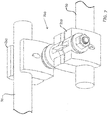
FIG. 2 is a perspective view of the external fixator assembly shown inFIG. 1 with a rod and a pin connected thereto; -
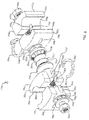
FIG. 3 is an exploded perspective view of the external fixator assembly shown inFIG. 1 ; -
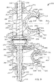
FIG. 4 is a side elevational view, in section, of the external fixator assembly shown inFIG. 1 ; -
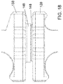
FIG. 5 is an exploded sectional view of a ratchet assembly used with the external fixator assembly shown inFIG. 1 ; -
FIG. 6 is a perspective view of external fixator assembly according to a second example being used to fixate adjacent bones; -
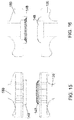
FIG. 7 is a perspective view of the external fixator assembly shown inFIG. 6 with rods connected thereto; -
FIG. 7A is a perspective view of the external fixator assembly shown inFIG. 6 with a rod and a pin connected thereto; -
FIG. 8 is an exploded perspective view of the external fixator assembly shown inFIG. 6 ; -
FIG. 9 is a side elevational view, in section, of the external fixator assembly shown inFIG. 6 ; -
FIG. 10 is a side elevational view, in section, of the external fixator assembly shown inFIG. 9 , with one shaft pivoted relative to the other shaft. -
FIG. 11 is a top perspective view of an external fixator assembly according to a third example being used to fixate adjacent bones; -
FIG. 12 is a close-up view of a clamp assembly of the external fixator assembly ofFIG. 11 ; -
FIG. 13 is a top perspective view of an external fixator assembly according to a fourth example being used to fixate adjacent bones; -
FIG. 14 is a close-up view of a pair of clamp assemblies of the external fixator assembly ofFIG. 13 ; -
FIG. 15 is a front view of an interface between a first clamp assembly and a second clamp assembly in accordance with some embodiments; -
FIG. 16 shows a cross-sectional view of the first clamp assembly and the second clamp assembly ofFIG. 15 ; -
FIG. 17 is a close-up view of teeth of a toothed locking half in accordance with some embodiments; -
FIG. 18 is a close-up view of a first clamp assembly and a second clamp assembly in a fully tightened construct in accordance with some embodiments; -
FIG. 19 is a side view of a rod in accordance with some embodiments; and -
FIG. 20 is a side view of a pin in accordance with some embodiments. -
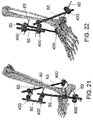
FIG. 21 is a rear perspective view of several external fixator assemblies in operation with bones of a foot. -
FIG. 22 is a front perspective view of several external fixator assemblies in operation with bones of a foot. - In the drawings, like numerals indicate like elements throughout. Certain terminology is used herein for convenience only and is not to be taken as a limitation on the present invention. The terminology includes the words specifically mentioned, derivatives thereof and words of similar import. The embodiments illustrated below are not intended to be exhaustive or to limit the invention to the precise form disclosed. These embodiments are chosen and described to best explain the principle of the invention and its application and practical use and to enable others skilled in the art to best utilize the invention.
- Reference herein to "one embodiment" or "an embodiment" means that a particular feature, structure, or characteristic described in connection with the embodiment can be included in at least one embodiment of the invention. The appearances of the phrase "in one embodiment" in various places in the specification are not necessarily all referring to the same embodiment, nor are separate or alternative embodiments necessarily mutually exclusive of other embodiments. The same applies to the term "implementation."
- As used in this application, the word "exemplary" is used herein to mean serving as an example, instance, or illustration. Any aspect or design described herein as "exemplary" is not necessarily to be construed as preferred or advantageous over other aspects or designs. Rather, use of the word exemplary is intended to present concepts in a concrete fashion.
- Additionally, the term "or" is intended to mean an inclusive "or" rather than an exclusive "or". That is, unless specified otherwise, or clear from context, "X employs A or B" is intended to mean any of the natural inclusive permutations. That is, if X employs A; X employs B; or X employs both A and B, then "X employs A or B" is satisfied under any of the foregoing instances. In addition, the articles "a" and "an" as used in this application and the appended claims should generally be construed to mean "one or more" unless specified otherwise or clear from context to be directed to a singular form.
- Unless explicitly stated otherwise, each numerical value and range should be interpreted as being approximate as if the word "about" or "approximately" preceded the value of the value or range.
- The use of figure numbers and/or figure reference labels in the claims is intended to identify one or more possible embodiments of the claimed subject matter in order to facilitate the interpretation of the claims. Such use is not to be construed as necessarily limiting the scope of those claims to the embodiments shown in the corresponding figures.
- It should be understood that the steps of the exemplary methods set forth herein are not necessarily required to be performed in the order described, and the order of the steps of such methods should be understood to be merely exemplary. Likewise, additional steps may be included in such methods, and certain steps may be omitted or combined, in methods consistent with various embodiments of the present invention.
- Although the elements in the following method claims, if any, are recited in a particular sequence with corresponding labeling, unless the claim recitations otherwise imply a particular sequence for implementing some or all of those elements, those elements are not necessarily intended to be limited to being implemented in that particular sequence.
- Also for purposes of this description, the terms "couple," "coupling," "coupled," "connect," "connecting," or "connected" refer to any manner known in the art or later developed of joining or connecting two or more elements directly or indirectly to one another, and the interposition of one or more additional elements is contemplated, although not required. Conversely, the terms "directly coupled," "directly connected," etc., imply the absence of such additional elements.
- The present disclosure provides embodiments of external fixators that can be used to secure bone fractures. The inventive external fixators provide connections that enable a surgeon to rapidly and securely stabilize the fracture.
- According to one embodiment, an external fixator system may include a plurality of external fixator assemblies configured to connect a plurality of pins, for example, positioned on opposite sides of a fractured bone, with one more rods. Each fixator assembly may include a plurality of clamp assemblies which are configured to rotate relative to one another when the fixator assembly is in an unlocked position. Once the relative positioning of the pins and/or rods is achieved, for example, to stabilize the fractured bone or bones, the fixator assemblies may be moved to a locked position, such that the clamp assemblies are fixed in position, thereby stabilizing the fracture.
- Referring to
FIGS. 1-5 , an external fixator assembly 100 ("fixator assembly 100") according to a first examples shown. As shown specifically inFIGS. 1 and1A ,fixator assembly 100 is used in conjunction withrods 50 and pins 60 to secure and stabilizeadjacent bones 70, 72 (shown inFIG. 1 ) or to stabilizebroken pieces FIG. 1A ). While afemur 70 and atibia 72 are shown inFIG. 1 , andfemur 70 is shown inFIG. 1A , those skilled in the art will recognize thatfixator assembly 100, along withrods 50 and pins 60, can be used to fixate other bones, and other bone pairs as well. Examples of bones may include, but are not limited to, the femur, tibia, fibula, humerus, radius, ulna, and phalanges. Although specific configurations of the external fixator systems are exemplified herein, it will be appreciated that the number, type, and location ofrods 50, pins 60, andfixator assemblies 100 can be modified or changed based on the type and location of the bone, fracture, surgeon preference, and the like. - As shown in
FIG. 2 ,fixator assembly 100 can be used to releasablysecure rod 50 andpin 60 through the use of a plurality of connector assemblies. In an exemplary embodiment,rod 50 can be constructed from a rigid material, such as, for example, a carbon fiber, and can optionally be coated with a material, such as, for example, titanium, to makerod 50 more compatible with MRI use. It is contemplated that therod 50 may be formed of any suitable material having suitable properties for this application.Rod 50 has a first diameter. The length ofrod 50 can be varied depending on the need for a particular application. -
Pin 60 can include a bone-engaging end, such as a self-tappingend 62, that is inserted intobone pin 60 may also be constructed from any suitable biocompatible material. Optionally, end 62 can be coated with an antimicrobial material, such as, for example, silver or silver ions, in order to reduce the likelihood of infection.Pin 60 has a second diameter, smaller than the first diameter ofrod 50. The length and diameter ofpin 60 can vary, depending on the patient or the injury, as well as surgeon preference. - While
FIGS. 1A and2 show fixator assembly 100 being used to secure asingle rod 50 and asingle pin 60, those skilled in the art will recognize thatfixator assembly 100 can, depending upon the particular situation and injury, be used to connect tworods 50, as shown inFIG. 1 , or even two pins 60 (not shown). - As shown in
FIG. 4 ,fixator assembly 100 includes alongitudinal axis 102 extending therethrough. As used herein, the terms "longitudinal", "longitudinally", "axial", and "axially" refer to directions along the length oflongitudinal axis 102 or to directions extending parallel tolongitudinal axis 102. Further, the terms "radial" and "radially" refer to directions extending perpendicular to or extending outwardly fromlongitudinal axis 102. - Referring now to
FIGS. 2 and3 ,fixator assembly 100 includes ashaft 110 and a plurality ofclamp assemblies shaft 110.Shaft 110 extends alonglongitudinal axis 102. A biasingmember 160 is disposed between adjacent of the plurality ofclamp assemblies assembly 170 securesclamp assemblies shaft 110. -
Shaft 110 has adistal end 112 and aproximal end 114 extending away from distal and 112. As used herein with respect tofixator assembly 100, the term "distal" refers to a direction toward the bottom of the page ofFIG. 4 , and the term "proximal" refers to a direction toward the top of the page ofFIG. 4 . -
Distal end 112 includes aradially extending flange 116 and at least oneflat surface 117 extending proximally offlange 116. WhileFIG. 4 shows twoflat surfaces 117, those skilled in the art will recognize thatshaft 110 can include more or less than twoflat surfaces 117. -
Proximal end 114 ofshaft 110 has at least oneexternal thread 118. Optionally, a length ofshaft 115 betweendistal end 112 andproximal end 114 can be generally circular, that is, devoid of any flat surfaces or threads.Shaft 110 is sufficiently long to allow for the insertion ofclamp assemblies assembly 170 thereon. -
Clamp assemblies shaft 110 fromdistal end 112 towardproximal end 114 such thatclamp assembly 120 engagesflange 116 and clampassembly 150 engagesclamp assembly 120. While twoclamp assemblies clamp assemblies fixator assembly 100. Alternatively, it can be envisioned that only asingle clamp assembly 120 is used withfixator assembly 100. -
Clamp assemblies Clamp assembly 120 includes alower member 122 and anupper member 124 extending proximally oflower member 122.Lower member 122 includes anaxially extending passage 126 that is sized to allowshaft 110 to extend therethrough.Passage 126 can include internalflat surfaces 128 that are adapted to engage withflat surfaces 117 onshaft 110 to preventlower member 122 ofclamp assembly 120 from rotating with respect toshaft 110. -
Lower member 122 includes a first generallyU-shaped portion 130 having a radius that is sized to receive a portion ofrod 50.Lower member 122 also includes a second generallyU-shaped portion 131, radially disposed away from firstconcave portion 130, having a radius that is sized to receive a portion ofpin 60. As shown inFIG. 3 ,lower member 122 also includes a plurality oftangs 132 extending outwardly therefrom in a proximal direction towardupper member 124. -
Upper member 124 includes anaxially extending passage 134 that is sized to allowshaft 110 to extend therethrough.Upper member 136 further includes a first generally invertedU-shaped portion 136 having a radius that is sized to receive a portion ofrod 50, such that, whenupper member 124 is biased towardlower member 122,rod 50 is received in acavity 138 formed by first generallyU-shaped portion 130 oflower member 122 and first generally invertedU-shaped portion 136 ofupper member 124. -
Upper member 124 also includes a second generally invertedU-shaped portion 140, radially disposed away from first generally invertedU-shaped portion 136, having a radius that is sized to receive a portion ofpin 60, such that, whenupper member 124 is biased towardlower member 122,pin 60 is received in acavity 142 formed by second generally invertedU-shaped portion 131 oflower member 122 and second generally invertedU-shaped 140 ofupper member 124. - As shown in
FIG. 3 ,upper member 124 also includes a plurality ofslots 144 formed therein, such that eachslot 144 is adapted to releasably receive atang 132 fromlower member 122, thereby preventingupper member 124 from rotating aboutlongitudinal axis 102 relative to lowermember 122.Upper member 124 also includes aspring cavity 146 that is sized to receive biasingmember 160. Atoothed locking half 148 surroundsspring cavity 146. -
Clamp assembly 150 is similar to clampassembly 120 with the exception that, instead of internalflat surfaces 128,clamp assembly 150 includes a member 122' having an axially extending passage 126' sufficiently larger than the diameter ofshaft 110 such thatclamp assembly 150 is freely rotatable aboutshaft 110 and is also rotatable relative to clampassembly 120. As shown inFIGS. 3 and4 ,clamp assembly 150 is inserted overshaft 110 "upside down" relative to clamp 120 such that toothed lockinghalf 148 ofclamp assembly 150 is engageable withtoothed locking half 148 ofclamp assembly 120 such that, whenclamp assembly 150 is biased againstclamp assembly 120,toothed locking half 148 ofclamp assembly 150 engages toothed lockinghalf 148 ofclamp assembly 120, preventing rotation ofclamp assembly 150 with respect to clampassembly 120. - Each
toothed locking half 148 includes a plurality of teeth or the like. In an example eachtoothed locking half 148 includes about 90 teeth, such thatclamp assembly 150 can be indexed with respect to clampassembly 120 about 4°. Those skilled in the art, however, will recognize that eachtoothed locking half 148 can include more or less than 90 teeth, such that the amount indexing ofclamp assembly 150 withrespect clamp assembly 120 is adjustable accordingly. - As shown in
FIG. 3 , biasingmember 160 is disposed betweenclamp assembly 120 and clampassembly 150 and is retained betweenclamp assembly 120 and clampassembly 150 withinspring cavities 146. In an exemplary embodiment, biasingmember 160 is a helical spring, although those skilled in the art will recognize that other types of biasing members can be used.Biasing member 160 biases clampassembly 120 and clampassembly 150 apart from each other, such thatclamp assembly 120 and clampassembly 150 securely engagerod 50 that may be inserted intocavity 138 and/or pin 160 that may be inserted intocavity 142. - Referring to
FIGS. 3-5 , ratchetassembly 170 is disposed overproximal end 114 ofshaft 110, such thatratchet assembly 170 biases clampassemblies distal end 112 ofshaft 110 andflange 116 so thatclamp assemblies washer 162 is axially disposed betweensecond clamp assembly 150 and ratchetassembly 170 to distribute compressive forces applied byratchet assembly 170 ontoclamp assembly 150. -
Ratchet assembly 170 comprises includes a ratcheting buttress 172 that is adapted to translate axially alongshaft 110 fromproximal end 114 towarddistal end 112. Ratcheting buttress 172 comprises a radially extendingannular flange 174 having an axially extendinghole 176 therein.Hole 176 is sized to allowshaft 112 to extend therethrough. Atang 177 extends longitudinally outwardly fromflange 174. - A plurality of
fingers 178 extend proximally aroundhole 176. Each of the plurality offingers 178 has a plurality of longitudinally spacedinternal ratchet teeth 180 adapted to engageexternal thread 118 onproximal end 114 ofshaft 110. Agap 181 extends between each ofadjacent fingers 178 to allowfingers 178 to bias away fromlongitudinal axis 102, thereby allowingthread 118 to ratchet along ratchetteeth 180 whenratchet assembly 170 is pressed ontoshaft 110. - A
ratchet housing 182 is disposed over ratcheting buttress 172.Ratchet housing 182 includes adistal end 184 having a radially extendinghousing flange 186 that is adapted to engage buttressflange 174.Flange 186 includes aslot 188 that is adapted to receivetang 177 fromflange 174 such that, whentang 177 is inserted intoslot 188, ratchethousing 182 is not rotatable relative to ratcheting buttress 172. - An exterior surface of
housing flange 186 includes a contoured surface, such as, for example, a knurled surface, that provides a gripping surface for the user to be able to manually rotateratchet housing 182 aboutshaft 110. An interior ofhousing flange 186 includes a first radially extendingcavity 190 adapted to receiveannular flange 174 ofratchet buttress 172. -
Ratchet housing 182 further includes aproximal body 192 having an internally threadedpassage 193 with at least oneinternal thread 194 adapted to threadably engageexternal thread 118 onshaft 110.Body 192 further comprises a plurality offlat surfaces 196 extending around a perimeter thereof.Flat surfaces 196 allow for the application of a tool, such as, for example, a wrench or other torquing device (not shown) to tightenfixator assembly 100 in order to secure rod(s) 50 and/or pin(s) 60.Body 192 also includes a second radially extendingcavity 198 that is adapted to receive the plurality offingers 178. As shown inFIG. 4 ,cavity 198 is sufficiently large to allowfingers 178 to bias away fromshaft 110 to allow ratcheting buttress 172 to be slid distally alongshaft 110. - To assemble
fixator assembly 100,first clamp assembly 120 is slid fromproximal end 114 ofshaft 110 todistal end 112shaft 110, bottoming out onflange 116.First clamp assembly 120 is aligned such thattoothed locking half 148 is facingproximal end 114 ofshaft 100. Next, biasingmember 160 is slid alongshaft 110 such that at least a portion of biasingmember 160 is seated withinspring cavity 146. -
Second clamp assembly 150 is then slid fromproximal end 114 ofshaft 110, towardfirst clamp assembly 120.Second clamp assembly 150 is aligned such thattoothed locking half 148 is facingdistal end 112 ofshaft 100 so that at least a remaining portion of biasingmember 160 is seated withinspring cavity 146 insecond clamp assembly 150 and so thattoothed locking half 148 ofsecond clamp assembly 150 is facingtoothed locking half 148 offirst clamp assembly 120. -
Washer 162 is slid overshaft 110.Ratchet assembly 170 is then slid overshaft 110 so thatinternal thread 194 engagesexternal threads 118 onshaft 110. At this point,cavities rod 50 be slid intocavity 138 andpin 60 to be slid intocavity 142 and also to allowsecond clamp assembly 150 to axially rotate relative tofirst clamp assembly 120. - In this condition, the surgeon can align
rod 50 andpin 60 in desired positions with respect tofixator assembly 100. The surgeon can then provisionally tightenratchet assembly 170 by further slidingratchet assembly 170 distally alongshaft 110 and then perform a final tightening offixator assembly 100 by applying a wrench or other court applying device (not shown) toflat surfaces 196 onratchet housing 182 androtating ratchet housing 182 relative toshaft 110. -
Ratchet assembly 170 allows for the rapid application ofclamp assemblies bar 50 and/orpin 60.Ratchet assembly 170 also provides a quick method for provisional tightening offixator assembly 100 while the surgeon is assemblingfixator assembly 100 with bar(s) 50 and pin(s) 60. Once set, a final tightening ofratchet assembly 170 can be applied using a torque limiting adapter, for example, under power. - A method of installing the external fixator system, for example, at the site of one or more broken bones, may include inserting one or
more pins 60 into the afflicted bone (for example, on opposite sides of the fracture); attaching one or morefixator assemblies 100 to eachpin 60; and securing the one ormore pins 60 toadjacent pins 60 by connecting one ormore rods 50 between adjacentfixator assemblies 100. If the construct needs to be extended, for example, to bridge multiple bones or multiple fractures, thesame fixator assembly 100 can also be used to connect two ormore rods 50 together. - An alternative example of an external fixator assembly 200 ("
fixator assembly 200") is shown inFIGS. 6-10 .FIG. 6 showsfixator assembly 200 being used with bothrods 50 and pins 60 to secure and stabilizeadjacent bones FIG. 7 showsfixator assembly 200 being used to secure tworods 50 in a generally parallel arrangement, whileFIG. 7A showsfixator assembly 200 being used to secure asingle rod 50 and asingle pin 60 in a skewed arrangement. - Referring to the exploded view of
fixator assembly 200, shown inFIG. 8 and the sectional view shown inFIG. 9 ,fixator assembly 200 includes afirst shaft 202 having afirst coupling end 204 and a firstfree end 206.First coupling end 204 has an outer diameter D1. Firstfree end 206 has a narrower diameter than outer diameter D1.First coupling end 204 terminates in afirst lip 207, having a generallyflat face 208 and a generally convexouter face 209. A firstlongitudinal axis 210 extends along the length offirst shaft 202. - Similarly, a
second shaft 212 has asecond coupling end 214 and a secondfree end 216.Second coupling end 214 has an outer diameter D2. Secondfree end 216 has a narrower diameter than outer diameter D2.Second coupling end 214 terminates in asecond lip 217, having a generally flat face 218 and a generally convexouter face 219. A secondlongitudinal axis 220 extends along the length ofsecond shaft 212. - A
coupling 230 pivotally retainsfirst coupling end 204 andsecond coupling end 214 therein. Coupling 230 includes a first cup, orclamshell portion 232 having a concave interface 234 that is contoured to receive generally convexouter face 209 offirst coupling end 204. Additionally,first clamshell portion 232 includes anopening 236, having a diameter D3, such that outer diameter D1 offirst coupling end 204 is smaller than the diameter D3, butfirst lip 207 is larger than the size ofopening 236 such that, whenfirst shaft 202 is inserted throughopening 236,first lip 207 is retained withinfirst clamshell portion 232. - Likewise, coupling 230 also includes a second cup, or
clamshell portion 242 having aconcave interface 244 that is contoured to receive generally convexouter face 219 ofsecond coupling end 214. Additionally,second clamshell portion 242 includes anopening 246, having a diameter D4, such that outer diameter D2 ofsecond coupling end 214 is smaller than the diameter D4, butsecond lip 217 is larger than the size ofopening 246 such that, whensecond shaft 212 is inserted throughopening 246,second lip 217 is retained withinsecond clamshell portion 242. - In an example,
first clamshell portion 232 includesfemale threads 238 andsecond clamshell portion 242 includes matchingmale threads 248 such thatfirst clamshell portion 232 can be threadedly connected tosecond clamshell portion 242. Optionally, to preventfirst clamshell portion 232 from being separated fromsecond clamshell portion 242,first clamshell portion 232 can be welded or otherwise permanently secured tosecond clamshell portion 242 at the connection offemale threads 238 andmale threads 248. - As used herein, the term "inner" is used to define a direction toward
coupling 230, and the term "outer" is used to define a direction away fromcoupling 230. Afirst clamp assembly 250 is disposed onfirst shaft 202 betweencoupling 230 and firstfree end 206 offirst shaft 202.First clamp assembly 250 includes a firstinner clamp member 252 disposed proximate tocoupling 230. Firstinner clamp member 252 has a firstinner slot 260. Firstinner slot 260 has anopen end 262, located at ashaft end 263, and ablind end 264, located at afinger end 265.Finger end 265 includes anarcuate cutout 266 that extends in an arc greater than 90°. Adrill passage 268 extends obliquely throughfinger end 265 to allow for the formation ofblind end 264. - First
inner clamp member 252 also includes aconcave surface 269 that engages concave interface 234 offirst clamshell portion 232 so that firstinner clamp member 252 is slidable along at least a portion of concave interface 234. Additionally, firstinner clamp member 252 includes a through-opening 270 sized to allowfirst shaft 202 to pass therethrough. Through-opening 270 is sized such that a minimum clearance exists between through-opening 270 andfirst shaft 202. -
First clamp assembly 250 further includes a firstouter clamp member 272 disposed proximate to firstfree end 206. Firstouter clamp member 272 has a first outer slot 280. First outer slot 280 has anopen end 282, located atshaft end 283, and ablind end 284, located at afinger end 285.Finger end 285 includes anarcuate cutout 286 that extends in an arc greater than 90°. Adrill passage 288 extends obliquely throughfinger end 285 to allow for the formation ofblind end 284. Similar toconcave surface 269 in firstinner clamp member 252, firstouter clamp member 272 also includes a concave surface 289. Additionally, firstouter clamp member 272 includes a through-opening 290 sized to allowfree end 206 offirst shaft 202 to pass therethrough. - In an example, first
outer clamp member 272 is generally a mirror image of firstinner clamp member 252 across a transverse axis 291. When firstinner clamp member 252 and firstouter clamp member 272 are assembled onshaft 202, as shown inFIG. 9 , a retainingcavity 292 is formed betweenfinger end 265 andfinger end 285. Retainingcavity 292 has a wall portion that extends an arc of greater than 180°. In an exemplary embodiment, retainingcavity 292 is sized to allow the insertion ofrod 50 therein. - A
first biasing member 294 is disposed in firstinner slot 260 and first outer slot 280. In an exemplary embodiment, first biasingmember 294 is a C-shaped spring having afirst end 296 that is inserted intoblind end 264 of firstinner slot 260 and asecond end 297 that is inserted intoblind end 284 of first outer slot 280 such that first biasingmember 294 biases firstinner clamp member 252 toward firstouter clamp member 272. - A
first washer 295 is disposed overfirst shaft 202 and against firstouter clamp member 272.First washer 295 has a contouredinner surface 297 for engagement with concave surface 289. Anut 298 is threaded ontofirst shaft 202 to securefirst clamp assembly 250 againstcoupling 230. - Similar to
first clamp assembly 250, asecond clamp assembly 350 is disposed onsecond shaft 212 betweencoupling 230 and secondfree end 216.Second clamp assembly 350 includes a secondinner clamp member 352 disposed proximate tocoupling 230. Secondinner clamp member 352 has a secondinner slot 360. Secondinner slot 360 has anopen end 362, located at ashaft end 363 and ablind end 364, located at afinger end 365.Finger end 365 includes anarcuate cutout 366 that extends in an arc greater than 90°. Adrill passage 368 extends obliquely throughfinger end 365 to allow for the formation ofblind end 364. - Second
inner clamp member 352 also includes a concave surface 369 that engagesconcave interface 334 ofsecond clamshell portion 242 so that secondinner clamp member 352 is slidable along at least a portion ofconcave interface 334. Additionally, secondinner clamp member 352 includes a through-opening 370 sized to allowsecond shaft 212 to pass therethrough. Through-opening 370 is sized such that a minimum clearance exists between through-opening 370 andsecond shaft 212. -
Second clamp assembly 350 further includes a secondouter clamp member 372 disposed proximate to secondfree end 216. Secondouter clamp member 372 has a secondouter slot 380. Secondouter slot 380 has anopen end 382, located atshaft end 383 and ablind end 384, located at afinger end 385.Finger end 385 includes anarcuate cutout 386 that extends in an arc greater than 90°. Adrill passage 388 extends obliquely throughfinger end 385 to allow for the formation ofblind end 384. Similar to concave surface 369 in secondinner clamp member 352, secondouter clamp member 372 also includes aconcave surface 389. Additionally, secondouter clamp member 372 includes a through-opening 390 sized to allowfree end 216 ofsecond shaft 212 to pass therethrough. - In an example, second
outer clamp member 372 is generally a mirror image of secondinner clamp member 352 across atransverse axis 391. When secondinner clamp member 352 and secondouter clamp member 372 are assembled onshaft 212, as shown inFIG. 9 , a retaining cavity 392 is formed betweenfinger end 365 andfinger end 385. Retaining cavity 392 has a wall portion that extends an arc of greater than 180°. In an exemplary embodiment, retaining cavity 392 is sized to allow the insertion ofpin 60 therein. - A
second biasing member 394 is disposed in secondinner slot 360 and secondouter slot 380. In an exemplary embodiment, second biasingmember 394 is a C-shaped spring having afirst end 396 that is inserted intoblind end 364 of secondinner slot 360 and asecond end 397 that is inserted intoblind end 384 of secondouter slot 380 such that second biasingmember 394 biases secondinner clamp member 352 toward secondouter clamp member 372. - A
second washer 395 is disposed oversecond shaft 212 and against secondouter clamp member 372.Second washer 395 has a contouredinner surface 397 for engagement withconcave surface 389. Anut 398 is threaded ontosecond shaft 212 to securesecond clamp assembly 350 againstcoupling 230. - To assemble
fixator assembly 200,first shaft 202 is inserted intofirst clamshell portion 232, such thatfirst lip 207 is seated infirst clamshell portion 232 andsecond shaft 212 andsecond shaft 212 is inserted intosecond clamshell portion 242, such thatsecond lip 217 is seated insecond clamshell portion 242. First andsecond clamshell portion - First
inner clamp member 252 and firstouter clamp 272 are placed next to each other, such that firstinner slot 260 and first outer slot 280 are aligned with each other, formingfirst clamp assembly 250. First biasingmember 294 is then inserted through firstinner slot 260 and first outer slot 280 such thatfirst end 296 of first biasingmember 294 is inserted intoblind end 264 of firstinner slot 260 andsecond end 297 of biasingmember 294 is inserted intoblind end 284 of first outer slot 280, thereby securing firstinner clamp member 252 and firstouter clamp member 272 to each other and providing a compressive force to biasfinger end 265 of firstinner clamp member 252 andfinger end 285 of firstouter clamp member 272 toward each other. -
First clamp assembly 250 is then slid overfirst shaft 202 such thatfirst shaft 202 extends through through-openings first shaft 202 extends through firstinner slot 260 and first outer slot 280 such thatfirst shaft 202 retains first biasingmember 294 in firstinner slot 260 and first outer slot 280.Washer 295 is slid overfirst shaft 202 andnut 298 is then threaded ontofirst shaft 202 to securefirst clamp assembly 250 againstcoupling 230. - Similarly, second
inner clamp member 352 and secondouter clamp 372 are placed next to each other, such that secondinner slot 360 and secondouter slot 380 are aligned with each other, formingsecond clamp assembly 350. Second biasingmember 394 is then inserted through secondinner slot 360 and secondouter slot 380 such thatfirst end 396 ofsecond biasing member 394 is inserted intoblind end 364 of secondinner slot 360 andsecond end 397 of biasingmember 394 is inserted intoblind end 384 of secondouter slot 380, thereby securing secondinner clamp member 352 and secondouter clamp member 372 to each other and providing a compressive force to biasfinger end 365 of secondinner clamp member 352 andfinger end 385 of secondouter clamp member 372 toward each other. -
Second clamp assembly 350 is then slid oversecond shaft 212 such thatsecond shaft 212 extends through through-openings second shaft 212 extends through secondinner slot 360 and second outer slot 280 such thatsecond shaft 212 retains second biasingmember 394 in secondinner slot 360 and secondouter slot 380.Washer 395 is slid oversecond shaft 212, andnut 398 is then threaded ontosecond shaft 212 to securesecond clamp assembly 350 againstcoupling 230. -
Rod 50 can be inserted into retainingcavity 292. Because retainingcavity 292 has a wall portion that defines an arc of greater than 180°, withrod 50 in retainingcavity 292, the compressive action of biasingmember 294 and the tightening ofnut 298 securely retainrod 50 within retainingcavity 292. - Similarly, pin 60 can be inserted into retaining cavity 392. Because retaining cavity 392 has a wall portion that defines an arc of greater than 180°, with
pin 60 in retaining cavity 392, the compressive action of biasingmember 394 and the tightening ofnut 298 securely retainpin 60 within retaining cavity 392. - In order to rotate
first clamp assembly 250 aboutfirst shaft 210,nut 298 can be loosened sufficiently to allow such rotation. The compressive action of first biasingmember 294 retainsrod 50 within retainingcavity 292 to allow such rotation, without adversely affecting the retention ofrod 50 withinfirst clamp assembly 250. - Likewise, in order to rotate
second clamp assembly 350 aboutsecond shaft 220,nut 398 can be loosened sufficiently to allow such rotation. The compressive action ofsecond biasing member 394 retainspin 60 within retaining cavity 392 to allow such rotation, without adversely affecting the retention ofpin 60 withinsecond clamp assembly 350. - Additionally, because diameter D1 of
first coupling end 204 is smaller than diameter D3 of opening 236 infirst clamshell portion 232 and diameter D2 ofsecond coupling end 214 is smaller than diameter D4 of opening 246 insecond clamshell portion 242, firstlongitudinal axis 210 offirst shaft 202 does not necessarily have to be collinear with secondlongitudinal axis 220 ofsecond shaft 212. As shown inFIG. 10 , firstlongitudinal axis 210 can extend at an oblique angle β relative to secondlongitudinal axis 220, allowing forfirst clamp assembly 250 to angularly pivot relative tosecond clamp assembly 350, thereby allowing for angular adjustment offirst clamp assembly 250 relative tosecond clamp assembly 350.FIG. 7A shows an example of such angular adjustment. - A method of installing the external fixator system, for example, at the site of one or more broken bones, may include inserting a
first pin 60 into the afflicted bone on one side of the fracture; inserting asecond pin 60 on an opposite side of the fracture; attaching afirst fixator assembly 200 to thefirst pin 60 and asecond fixator assembly 200 to thesecond pin 60; articulating the first orsecond clamp assembly second clamp assembly rod 50; connecting therod 50 between the first andsecond fixator assemblies 200 in order to secure the first andsecond pins 60 together. If the construct needs to be extended, for example, to bridge multiple bones or multiple fractures, a thirdfixator assembly 200 may be articulated and positioned to secure and connect therod 50 to anadditional rod 50. -
FIG. 11 is a top perspective view of an external fixator assembly according to a third example being used to fixate adjacent bones. Theexternal fixator assembly 300 comprises similar features as in prior embodiments, including afirst clamp assembly 320, asecond clamp assembly 350, aratchet assembly 370, and ashaft 310 extending through each of the components. Thefirst clamp assembly 320 comprises an upper member 324' operably attached to a lower member 321', thereby forming a pair of slots for receiving one or more pins or rods. Likewise, thesecond clamp assembly 350 comprises anupper member 324 operably attached to alower member 321, thereby forming a pair of slots for receiving one or more pins or rods. However, in the present embodiment, at least one of the slots for receiving the one or more pins or rods is formed by one or more flat surfaces (shown inFIG. 12 ). By providing such flat surfaces, this advantageously provides a distinctly shaped slot that eases both insertion and removal of any pin or rod that is inserted within the slot. - In some examples, the
first clamp assembly 320 comprises an upper member 324' having a first downward facing recessed portion 336' and a second downward facing recessed portion 340'. In some embodiments, the first downward facing recessed portion 336' and the second downward facing recessed portion 340' are U-shaped or V-shaped. In addition, thefirst clamp assembly 320 further comprises a lower member 321' having a first upward facing recessed portion 330' and a second upward facing recessed portion 331'. In some embodiments, the first upward facing recessed portion 330' and the second upward facing recessed portion 331' are U-shaped or V-shaped. In some embodiments, the first downward facing recessed portion 336' faces the first upward facing recessed portion 330', thereby forming a first slot in the first clamp assembly for receiving a rod or pin. In some embodiments, the second downward facing recessed portion 340' faces the second upward facing recessed portion 331', thereby forming a second slot in the first clamp assembly for receiving a rod or pin. In some embodiments, the first slot and the second slot in thefirst clamp assembly 320 are the same size. In other embodiments, the first slot and the second slot in thefirst clamp assembly 320 are of different sizes. - In some examples, the
second clamp assembly 350 comprises anupper member 324 having a first downward facing recessedportion 336 and a second downward facing recessedportion 340. In some embodiments, the first downward facing recessedportion 336 and the second downward facing recessedportion 340 are U-shaped or V-shaped. In addition, thesecond clamp assembly 350 comprises an upward facingflat portion 330 and an upward facing recessedportion 331. In some embodiments, the first downward facing recessedportion 336 faces the first upward facingflat portion 330, thereby forming a first slot in the second clamp assembly for receiving a rod or pin. In some embodiments, the second downward facing recessedportion 340 faces the second upward facing recessedportion 331, thereby forming a second slot in the second clamp assembly for receiving a rod or pin. -
FIG. 12 is a close-up view of a clamp assembly of the external fixator assembly ofFIG. 11 . From this view, one can see how theclamp assembly 350 includes a first slot for receiving a rod or a pin and a second slot for receiving a rod or a pin, wherein the first slot is different from the second slot. The first slot in theclamp assembly 350 is formed by a first downward facing recessedportion 336 which opposes an upward facingflat portion 330, while the second slot in theclamp assembly 350 is formed by a second downward facing recessedportion 340 which opposes an upward facing recessedportion 331. In other words, the first slot is formed by a single arc opposing a flat surface, while the second slot is formed by opposing double arcs. - As shown in
FIG. 12 , the first slot further includesflat surfaces flat portion 330 and the recessedportion 336, thereby connecting the portions to form the first slot. By providing a first slot with the flat surfaces, this advantageously creates a slot whereby a rod or pin can be easily inserted, but also easily removed from the first slot. As shown inFIG. 12 , the second slot is formed by the second downward facing recessedportion 340 transitioning into the upward facing recessedportion 331, thereby forming a slot formed of double arcs. -
FIG. 13 is a top perspective view of an external fixator assembly according to a fourth example being used to fixate adjacent bones. Theexternal fixator assembly 400 comprises similar features as in prior embodiments, including afirst clamp assembly 420, asecond clamp assembly 450, aratchet assembly 470, and ashaft 410 extending through each of the components. Thefirst clamp assembly 420 comprises an upper member 424' operably attached to a lower member 421', thereby forming a pair of slots for receiving one or more pins or rods. However, thesecond clamp assembly 450 comprises anupper member 424 operably attached to alower member 421, whereby only a single slot is formed for receiving a single rod. As shown inFIG. 13 , the single slot is opposed to a rod/pinfree zone 433. In other words, theexternal fixator 400 including thefirst clamp assembly 420 and thesecond clamp assembly 450 includes a total of three slots for receiving one or more pins or rods. By providing asecond clamp assembly 450 having a single slot for receiving a rod, this advantageously provides a more simplistic connection mechanism and reduces the risk of confusion to a surgeon during surgery. - According to the present invention, however, the single slot of the
second clamp assembly 450 receives a pin instead of a rod, wherein the pin is sized and configured to extend into a tibial bone. -
FIG. 14 is a close-up view of a pair of clamp assemblies of the external fixator assembly ofFIG. 13 . From this view, one can see how theclamp assembly 450 includes a first slot for receiving a rod that is opposed to a rod/pinfree zone 433. The first slot in theclamp assembly 450 is formed by a first downward facing recessedportion 436 which opposes a first upward facing recessedportion 430. The rod/pinfree zone 433 is formed of twoflat surfaces flat surfaces - In contrast to the
clamp assembly 450, theclamp assembly 420 includes two opposing slots for receiving one or more rods and/or pins. The first slot is formed of a first downward facing recessed portion 436' which opposes a first upward facing recessed portion 430', while the second slot is formed of a second downward facing recessed portion 440' which opposes a second upward facing recessed portion 431'. As shown inFIG. 14 , the first slot for receiving a rod is larger than the second slot for receiving a pin. -
FIG. 15 is a front view of an interface between a first clamp assembly and a second clamp assembly in accordance with some embodiments. Thefirst clamp assembly 120 comprises an upwardly extendingtoothed locking half 148, while thesecond clamp assembly 150 comprises a downwardly extending toothed locking half. In some embodiments, thefirst clamp assembly 120 comprises an upwardly extendingtoothed locking half 148 in the form of a female mating feature, while thesecond clamp assembly 150 comprises a downwardly extendingtoothed locking half 148 in the form of a male mating feature that is received in the female mating feature. In some embodiments, both the downwardly extendingtoothed locking half 148 and the upwardly extending toothed locking half comprise grooves in the form of a beveled star grind. When both of the lockinghalves 148 are engaged with one another, the beveled star grinds engage one another, thereby preventing relative rotation between thefirst clamp assembly 120 and thesecond clamp assembly 150. In addition, advantageously the elevated and indented portions of the male and female mating features also allow for the grooves of the star grinds to self-align once tightened. Once thefirst clamp assembly 120 and thesecond clamp assembly 150 are tightened, the beveled star grinds are completely enclosed and not visible externally (as shown inFIG. 18 ). The beveled star grinds disclosed herein can be used with any of the embodiments above of external fixators. -
FIG. 16 shows a cross-sectional view of the first clamp assembly and the second clamp assembly ofFIG. 15 . From this view, one can see how thesecond clamp assembly 150 includes atoothed locking half 148 in the form of an internal beveled star grind. The beveled star grind of thesecond clamp assembly 150 engages the beveled star grind of thefirst clamp assembly 120, as noted above. -
FIG. 17 is a close-up view of teeth of a toothed locking half in accordance with some embodiments. Theteeth 147 of thetoothed locking half 148 are arranged concentrically around an opening for receiving a shaft (e.g., shaft 110) of theclamp assembly 150, thereby forming a beveled star grind. In some embodiments, theteeth 147 are formed continuously around the opening, while in other embodiments, theteeth 147 are formed intermittently around the opening. -
FIG. 18 is a close-up view of a first clamp assembly and a second clamp assembly in a fully tightened construct in accordance with some embodiments. In the fully tightened construct, thefirst clamp assembly 120 and thesecond clamp assembly 150 are engaged with one another such that their star grind components are not visible. Advantageously, the beveled star grinds will allow for the clamp assemblies to resist rotation relative to one another. In addition, they will also provide a strong consistent hold each time the clamp assemblies are tightened. -
FIG. 19 is a side view of a rod to be used with any of the external fixators above in accordance with some embodiments. Therod 50 can be formed of a biocompatible material. In some embodiments, therod 50 is formed of carbon fiber. In some embodiments, therod 50 can be coated with an additional material to make it more compatible for MRI use. -
FIG. 20 is a side view of a pin to be used with any of the external fixators above in accordance with some embodiments. Thepin 60 can be comprised of aproximal portion 61 and adistal portion 62. Theproximal portion 61 can comprise one or more grooves or features that allow for quick connection to a hand-held tool. In some embodiments, theproximal portion 61 comprises an AO quick connect adapter. Thedistal portion 62 can comprise one or more threads that can be inserted into bone. In some embodiments, two or more pins will be used with any of the external fixators described above. The pins that can be self-tapping and/or self-tapping/self-drilling pins. In some embodiments, the pins can advantageously have a hydroxyal apatite coating in order to prevent pin tract infection. The length and diameter of the pins can vary depending on the patients and surgeon preference. In some embodiments, a pin is provided that can have grooves cut along its shank such that if the end of the pin is cut off, removal can still be easily achieved with another instrument (e.g., a keyless chuck). One skilled in the art that different types of pins can be used with any of the external fixators described above. For example, in some embodiments, two pins can be used with an external fixator whereby the first pin has an AO quick connect adapter, while the second pin does not have an AO quick connect adapter. -
FIG. 21 is a rear perspective view of several external fixator assemblies in operation with bones of a foot.FIG. 22 is a front perspective view of several external fixator assemblies in operation with bones of a foot. In these embodiments, one or moreexternal fixator assemblies 400 are assembled with one ormore rods 50 or pins 60 to stabilize the bones of a foot. In some embodiments, a pair ofexternal fixator assemblies 400 receive one ormore pins 60 therethrough that extend into atibia bone 74. Theseexternal fixator assemblies 400 also receive one ormore rods 50 that connect them to lowerexternal fixator assemblies 400. These lowerexternal fixator assemblies 400 include one ormore pins 60 that extend into a calcaneus (or heel)bone 72. One skilled in the art will appreciate that the construct shown inFIGS. 21 and 22 is not limiting, and that therods 50 and pins 60 can extend into other bones of the leg or foot, including the fibula, tarsals, metatarsals, and/or phalanges. - It will be further understood that various changes in the details, materials, and arrangements of the parts which have been described and illustrated in order to explain the nature of this invention may be made by those skilled in the art without departing from the scope of the invention as expressed in the following claims.
Claims (10)
- An external fixator assembly (400) comprising:a first clamp assembly (420), wherein the first clamp assembly (420) comprises a first upper member (424') and a first lower member (421') operably connected to one another, wherein the first upper member (424') and the first lower member (421') form a first slot (430', 436') in opposition to a second slot (431', 440');a second clamp assembly (450), wherein the second clamp assembly (450) comprises a second upper member (424) and a second lower member (421) operably connected to one another, wherein the second upper member (424) and the second lower member (421) form a third slot (430, 436) in opposition to a pin or rod free zone 433;a rod (50) received within the first slot or second slot of the first clamp assembly (420); characterized in that the assembly further comprisesa pin (60) received within the third slot of the second clamp assembly (450), wherein the pin (60) is sized and configured to extend into a tibial bone.
- The external fixator assembly of claim 1, wherein the first slot is formed by an arced surface (436') formed in the first upper member (424') and an arced surface (430') formed in the first lower member (421').
- The external fixator assembly of claim 1, wherein the pin or rod free zone (433) is comprised of at least one flat surface.
- The external fixator assembly of claim 3, wherein the pin or rod free zone (433) is comprised of a first flat surface and a second flat surface that form a recess sized and configured such that a pin or rod would not be retained therein.
- The external fixator assembly of claim 3, wherein the pin or rod free zone (433) includes a recess formed therein.
- The external fixator assembly of claim 1, wherein the external fixator assembly (400) further comprises a shaft (410) that extends through the first clamp assembly (420) and the second clamp assembly (450).
- The external fixator assembly of claim 6, further comprising a spring extending around the shaft (410).
- The external fixator assembly of claim 6, further comprising a ratchet assembly operably attached to the shaft (410).
- The external fixator assembly of claim 1, wherein the first clamp assembly (420) comprises a first star grind and the second clamp assembly comprises a second star grind.
- The external fixator assembly of claim 9, wherein the first star grind and the second star grind are engaged with one another.
Applications Claiming Priority (1)
| Application Number | Priority Date | Filing Date | Title |
|---|---|---|---|
| US15/455,317 US10136919B2 (en) | 2015-12-03 | 2017-03-10 | External fixator assembly |
Publications (2)
| Publication Number | Publication Date |
|---|---|
| EP3372178A1 EP3372178A1 (en) | 2018-09-12 |
| EP3372178B1 true EP3372178B1 (en) | 2020-09-09 |
Family
ID=61581086
Family Applications (1)
| Application Number | Title | Priority Date | Filing Date |
|---|---|---|---|
| EP18160397.8A Active EP3372178B1 (en) | 2017-03-10 | 2018-03-07 | External fixator assembly |
Country Status (2)
| Country | Link |
|---|---|
| EP (1) | EP3372178B1 (en) |
| JP (1) | JP2018161466A (en) |
Families Citing this family (2)
| Publication number | Priority date | Publication date | Assignee | Title |
|---|---|---|---|---|
| WO2023080993A1 (en) * | 2021-11-08 | 2023-05-11 | Smith & Nephew, Inc. | Systems and methods for using a femoral array clamp |
| US11413070B2 (en) | 2021-11-22 | 2022-08-16 | New Standard Device, LLC | Locking clamp and external fixation horns |
Family Cites Families (4)
| Publication number | Priority date | Publication date | Assignee | Title |
|---|---|---|---|---|
| EP2672907B1 (en) * | 2011-02-11 | 2015-07-01 | ORTHOFIX S.r.l. | Clamp for temporary or definitive external orthopaedic fixation, and external fixation system comprising said clamp |
| US20170281236A1 (en) * | 2014-09-04 | 2017-10-05 | Mikai S.P.A. | External fixation clamp |
| US9872707B2 (en) * | 2015-12-03 | 2018-01-23 | Globus Medical, Inc. | External fixator assembly |
| US9943337B2 (en) * | 2015-12-03 | 2018-04-17 | Globus Medical, Inc. | External fixator assembly |
-
2018
- 2018-03-07 EP EP18160397.8A patent/EP3372178B1/en active Active
- 2018-03-08 JP JP2018041749A patent/JP2018161466A/en active Pending
Also Published As
| Publication number | Publication date |
|---|---|
| JP2018161466A (en) | 2018-10-18 |
| EP3372178A1 (en) | 2018-09-12 |
Similar Documents
| Publication | Publication Date | Title |
|---|---|---|
| US10828066B2 (en) | External fixator assembly | |
| US10499951B2 (en) | External fixator assembly | |
| US10433874B2 (en) | External fixator assembly | |
| US11672566B2 (en) | External fixator assembly | |
| US9539040B2 (en) | Locking and lagging bone screws | |
| US7758582B2 (en) | Device and methods for placing external fixation elements | |
| US20160296261A1 (en) | Lockable intramedullary fixation device | |
| CN109069194A (en) | For temporarily fastening the medical instrument of polyaxial pedicle screw | |
| US10743918B2 (en) | External fixation connection rod with female attachment | |
| US20140243825A1 (en) | Compressible device assembly and associated method for facilitating healing between bones | |
| EP3372178B1 (en) | External fixator assembly | |
| EP3381387B1 (en) | External fixator assembly | |
| CN112512446B (en) | External fixing connecting rod with female accessory | |
| CN112074245A (en) | Improved dynamic device for orthopedic fixation devices |
Legal Events
| Date | Code | Title | Description |
|---|---|---|---|
| PUAI | Public reference made under article 153(3) epc to a published international application that has entered the european phase |
Free format text: ORIGINAL CODE: 0009012 |
|
| STAA | Information on the status of an ep patent application or granted ep patent |
Free format text: STATUS: THE APPLICATION HAS BEEN PUBLISHED |
|
| AK | Designated contracting states |
Kind code of ref document: A1 Designated state(s): AL AT BE BG CH CY CZ DE DK EE ES FI FR GB GR HR HU IE IS IT LI LT LU LV MC MK MT NL NO PL PT RO RS SE SI SK SM TR |
|
| AX | Request for extension of the european patent |
Extension state: BA ME |
|
| STAA | Information on the status of an ep patent application or granted ep patent |
Free format text: STATUS: REQUEST FOR EXAMINATION WAS MADE |
|
| 17P | Request for examination filed |
Effective date: 20190228 |
|
| RBV | Designated contracting states (corrected) |
Designated state(s): AL AT BE BG CH CY CZ DE DK EE ES FI FR GB GR HR HU IE IS IT LI LT LU LV MC MK MT NL NO PL PT RO RS SE SI SK SM TR |
|
| GRAP | Despatch of communication of intention to grant a patent |
Free format text: ORIGINAL CODE: EPIDOSNIGR1 |
|
| STAA | Information on the status of an ep patent application or granted ep patent |
Free format text: STATUS: GRANT OF PATENT IS INTENDED |
|
| RIC1 | Information provided on ipc code assigned before grant |
Ipc: A61B 17/64 20060101AFI20200518BHEP |
|
| INTG | Intention to grant announced |
Effective date: 20200616 |
|
| RIN1 | Information on inventor provided before grant (corrected) |
Inventor name: JANSEN, DAVID R. Inventor name: DAVIS, BARCLAY Inventor name: MUNIZ, SERGIO |
|
| GRAS | Grant fee paid |
Free format text: ORIGINAL CODE: EPIDOSNIGR3 |
|
| GRAA | (expected) grant |
Free format text: ORIGINAL CODE: 0009210 |
|
| STAA | Information on the status of an ep patent application or granted ep patent |
Free format text: STATUS: THE PATENT HAS BEEN GRANTED |
|
| AK | Designated contracting states |
Kind code of ref document: B1 Designated state(s): AL AT BE BG CH CY CZ DE DK EE ES FI FR GB GR HR HU IE IS IT LI LT LU LV MC MK MT NL NO PL PT RO RS SE SI SK SM TR |
|
| REG | Reference to a national code |
Ref country code: GB Ref legal event code: FG4D |
|
| REG | Reference to a national code |
Ref country code: AT Ref legal event code: REF Ref document number: 1310586 Country of ref document: AT Kind code of ref document: T Effective date: 20200915 Ref country code: CH Ref legal event code: EP |
|
| REG | Reference to a national code |
Ref country code: IE Ref legal event code: FG4D |
|
| REG | Reference to a national code |
Ref country code: DE Ref legal event code: R096 Ref document number: 602018007490 Country of ref document: DE |
|
| REG | Reference to a national code |
Ref country code: LT Ref legal event code: MG4D |
|
| PG25 | Lapsed in a contracting state [announced via postgrant information from national office to epo] |
Ref country code: FI Free format text: LAPSE BECAUSE OF FAILURE TO SUBMIT A TRANSLATION OF THE DESCRIPTION OR TO PAY THE FEE WITHIN THE PRESCRIBED TIME-LIMIT Effective date: 20200909 Ref country code: GR Free format text: LAPSE BECAUSE OF FAILURE TO SUBMIT A TRANSLATION OF THE DESCRIPTION OR TO PAY THE FEE WITHIN THE PRESCRIBED TIME-LIMIT Effective date: 20201210 Ref country code: HR Free format text: LAPSE BECAUSE OF FAILURE TO SUBMIT A TRANSLATION OF THE DESCRIPTION OR TO PAY THE FEE WITHIN THE PRESCRIBED TIME-LIMIT Effective date: 20200909 Ref country code: LT Free format text: LAPSE BECAUSE OF FAILURE TO SUBMIT A TRANSLATION OF THE DESCRIPTION OR TO PAY THE FEE WITHIN THE PRESCRIBED TIME-LIMIT Effective date: 20200909 Ref country code: NO Free format text: LAPSE BECAUSE OF FAILURE TO SUBMIT A TRANSLATION OF THE DESCRIPTION OR TO PAY THE FEE WITHIN THE PRESCRIBED TIME-LIMIT Effective date: 20201209 Ref country code: SE Free format text: LAPSE BECAUSE OF FAILURE TO SUBMIT A TRANSLATION OF THE DESCRIPTION OR TO PAY THE FEE WITHIN THE PRESCRIBED TIME-LIMIT Effective date: 20200909 Ref country code: BG Free format text: LAPSE BECAUSE OF FAILURE TO SUBMIT A TRANSLATION OF THE DESCRIPTION OR TO PAY THE FEE WITHIN THE PRESCRIBED TIME-LIMIT Effective date: 20201209 |
|
| REG | Reference to a national code |
Ref country code: AT Ref legal event code: MK05 Ref document number: 1310586 Country of ref document: AT Kind code of ref document: T Effective date: 20200909 |
|
| REG | Reference to a national code |
Ref country code: NL Ref legal event code: MP Effective date: 20200909 |
|
| PG25 | Lapsed in a contracting state [announced via postgrant information from national office to epo] |
Ref country code: RS Free format text: LAPSE BECAUSE OF FAILURE TO SUBMIT A TRANSLATION OF THE DESCRIPTION OR TO PAY THE FEE WITHIN THE PRESCRIBED TIME-LIMIT Effective date: 20200909 Ref country code: LV Free format text: LAPSE BECAUSE OF FAILURE TO SUBMIT A TRANSLATION OF THE DESCRIPTION OR TO PAY THE FEE WITHIN THE PRESCRIBED TIME-LIMIT Effective date: 20200909 Ref country code: PL Free format text: LAPSE BECAUSE OF FAILURE TO SUBMIT A TRANSLATION OF THE DESCRIPTION OR TO PAY THE FEE WITHIN THE PRESCRIBED TIME-LIMIT Effective date: 20200909 |
|
| PG25 | Lapsed in a contracting state [announced via postgrant information from national office to epo] |
Ref country code: EE Free format text: LAPSE BECAUSE OF FAILURE TO SUBMIT A TRANSLATION OF THE DESCRIPTION OR TO PAY THE FEE WITHIN THE PRESCRIBED TIME-LIMIT Effective date: 20200909 Ref country code: RO Free format text: LAPSE BECAUSE OF FAILURE TO SUBMIT A TRANSLATION OF THE DESCRIPTION OR TO PAY THE FEE WITHIN THE PRESCRIBED TIME-LIMIT Effective date: 20200909 Ref country code: PT Free format text: LAPSE BECAUSE OF FAILURE TO SUBMIT A TRANSLATION OF THE DESCRIPTION OR TO PAY THE FEE WITHIN THE PRESCRIBED TIME-LIMIT Effective date: 20210111 Ref country code: CZ Free format text: LAPSE BECAUSE OF FAILURE TO SUBMIT A TRANSLATION OF THE DESCRIPTION OR TO PAY THE FEE WITHIN THE PRESCRIBED TIME-LIMIT Effective date: 20200909 Ref country code: SM Free format text: LAPSE BECAUSE OF FAILURE TO SUBMIT A TRANSLATION OF THE DESCRIPTION OR TO PAY THE FEE WITHIN THE PRESCRIBED TIME-LIMIT Effective date: 20200909 |
|
| PG25 | Lapsed in a contracting state [announced via postgrant information from national office to epo] |
Ref country code: IS Free format text: LAPSE BECAUSE OF FAILURE TO SUBMIT A TRANSLATION OF THE DESCRIPTION OR TO PAY THE FEE WITHIN THE PRESCRIBED TIME-LIMIT Effective date: 20210109 Ref country code: AL Free format text: LAPSE BECAUSE OF FAILURE TO SUBMIT A TRANSLATION OF THE DESCRIPTION OR TO PAY THE FEE WITHIN THE PRESCRIBED TIME-LIMIT Effective date: 20200909 Ref country code: AT Free format text: LAPSE BECAUSE OF FAILURE TO SUBMIT A TRANSLATION OF THE DESCRIPTION OR TO PAY THE FEE WITHIN THE PRESCRIBED TIME-LIMIT Effective date: 20200909 Ref country code: ES Free format text: LAPSE BECAUSE OF FAILURE TO SUBMIT A TRANSLATION OF THE DESCRIPTION OR TO PAY THE FEE WITHIN THE PRESCRIBED TIME-LIMIT Effective date: 20200909 |
|
| REG | Reference to a national code |
Ref country code: DE Ref legal event code: R097 Ref document number: 602018007490 Country of ref document: DE |
|
| PG25 | Lapsed in a contracting state [announced via postgrant information from national office to epo] |
Ref country code: SK Free format text: LAPSE BECAUSE OF FAILURE TO SUBMIT A TRANSLATION OF THE DESCRIPTION OR TO PAY THE FEE WITHIN THE PRESCRIBED TIME-LIMIT Effective date: 20200909 |
|
| PLBE | No opposition filed within time limit |
Free format text: ORIGINAL CODE: 0009261 |
|
| STAA | Information on the status of an ep patent application or granted ep patent |
Free format text: STATUS: NO OPPOSITION FILED WITHIN TIME LIMIT |
|
| 26N | No opposition filed |
Effective date: 20210610 |
|
| PG25 | Lapsed in a contracting state [announced via postgrant information from national office to epo] |
Ref country code: SI Free format text: LAPSE BECAUSE OF FAILURE TO SUBMIT A TRANSLATION OF THE DESCRIPTION OR TO PAY THE FEE WITHIN THE PRESCRIBED TIME-LIMIT Effective date: 20200909 Ref country code: DK Free format text: LAPSE BECAUSE OF FAILURE TO SUBMIT A TRANSLATION OF THE DESCRIPTION OR TO PAY THE FEE WITHIN THE PRESCRIBED TIME-LIMIT Effective date: 20200909 |
|
| PG25 | Lapsed in a contracting state [announced via postgrant information from national office to epo] |
Ref country code: MC Free format text: LAPSE BECAUSE OF FAILURE TO SUBMIT A TRANSLATION OF THE DESCRIPTION OR TO PAY THE FEE WITHIN THE PRESCRIBED TIME-LIMIT Effective date: 20200909 Ref country code: IT Free format text: LAPSE BECAUSE OF FAILURE TO SUBMIT A TRANSLATION OF THE DESCRIPTION OR TO PAY THE FEE WITHIN THE PRESCRIBED TIME-LIMIT Effective date: 20200909 |
|
| REG | Reference to a national code |
Ref country code: CH Ref legal event code: PL |
|
| REG | Reference to a national code |
Ref country code: BE Ref legal event code: MM Effective date: 20210331 |
|
| PG25 | Lapsed in a contracting state [announced via postgrant information from national office to epo] |
Ref country code: IE Free format text: LAPSE BECAUSE OF NON-PAYMENT OF DUE FEES Effective date: 20210307 Ref country code: FR Free format text: LAPSE BECAUSE OF NON-PAYMENT OF DUE FEES Effective date: 20210331 Ref country code: CH Free format text: LAPSE BECAUSE OF NON-PAYMENT OF DUE FEES Effective date: 20210331 Ref country code: LU Free format text: LAPSE BECAUSE OF NON-PAYMENT OF DUE FEES Effective date: 20210307 Ref country code: LI Free format text: LAPSE BECAUSE OF NON-PAYMENT OF DUE FEES Effective date: 20210331 |
|
| PG25 | Lapsed in a contracting state [announced via postgrant information from national office to epo] |
Ref country code: BE Free format text: LAPSE BECAUSE OF NON-PAYMENT OF DUE FEES Effective date: 20210331 |
|
| PGFP | Annual fee paid to national office [announced via postgrant information from national office to epo] |
Ref country code: GB Payment date: 20230327 Year of fee payment: 6 Ref country code: DE Payment date: 20230329 Year of fee payment: 6 |
|
| PG25 | Lapsed in a contracting state [announced via postgrant information from national office to epo] |
Ref country code: NL Free format text: LAPSE BECAUSE OF NON-PAYMENT OF DUE FEES Effective date: 20200923 Ref country code: CY Free format text: LAPSE BECAUSE OF FAILURE TO SUBMIT A TRANSLATION OF THE DESCRIPTION OR TO PAY THE FEE WITHIN THE PRESCRIBED TIME-LIMIT Effective date: 20200909 |
|
| PG25 | Lapsed in a contracting state [announced via postgrant information from national office to epo] |
Ref country code: HU Free format text: LAPSE BECAUSE OF FAILURE TO SUBMIT A TRANSLATION OF THE DESCRIPTION OR TO PAY THE FEE WITHIN THE PRESCRIBED TIME-LIMIT; INVALID AB INITIO Effective date: 20180307 |