EP3372016B1 - Telekommunikationsvorrichtung und -verfahren - Google Patents
Telekommunikationsvorrichtung und -verfahren Download PDFInfo
- Publication number
- EP3372016B1 EP3372016B1 EP16784454.7A EP16784454A EP3372016B1 EP 3372016 B1 EP3372016 B1 EP 3372016B1 EP 16784454 A EP16784454 A EP 16784454A EP 3372016 B1 EP3372016 B1 EP 3372016B1
- Authority
- EP
- European Patent Office
- Prior art keywords
- terminal device
- data
- block
- operating mode
- exchange
- Prior art date
- Legal status (The legal status is an assumption and is not a legal conclusion. Google has not performed a legal analysis and makes no representation as to the accuracy of the status listed.)
- Active
Links
Images



Classifications
-
- H—ELECTRICITY
- H04—ELECTRIC COMMUNICATION TECHNIQUE
- H04W—WIRELESS COMMUNICATION NETWORKS
- H04W52/00—Power management, e.g. Transmission Power Control [TPC] or power classes
- H04W52/02—Power saving arrangements
- H04W52/0209—Power saving arrangements in terminal devices
- H04W52/0225—Power saving arrangements in terminal devices using monitoring of external events, e.g. the presence of a signal
- H04W52/0229—Power saving arrangements in terminal devices using monitoring of external events, e.g. the presence of a signal where the received signal is a wanted signal
-
- H—ELECTRICITY
- H04—ELECTRIC COMMUNICATION TECHNIQUE
- H04W—WIRELESS COMMUNICATION NETWORKS
- H04W52/00—Power management, e.g. Transmission Power Control [TPC] or power classes
- H04W52/02—Power saving arrangements
- H04W52/0209—Power saving arrangements in terminal devices
- H04W52/0212—Power saving arrangements in terminal devices managed by the network, e.g. network or access point is leader and terminal is follower
-
- H—ELECTRICITY
- H04—ELECTRIC COMMUNICATION TECHNIQUE
- H04W—WIRELESS COMMUNICATION NETWORKS
- H04W52/00—Power management, e.g. Transmission Power Control [TPC] or power classes
- H04W52/02—Power saving arrangements
- H04W52/0209—Power saving arrangements in terminal devices
- H04W52/0212—Power saving arrangements in terminal devices managed by the network, e.g. network or access point is leader and terminal is follower
- H04W52/0216—Power saving arrangements in terminal devices managed by the network, e.g. network or access point is leader and terminal is follower using a pre-established activity schedule, e.g. traffic indication frame
-
- H—ELECTRICITY
- H04—ELECTRIC COMMUNICATION TECHNIQUE
- H04W—WIRELESS COMMUNICATION NETWORKS
- H04W52/00—Power management, e.g. Transmission Power Control [TPC] or power classes
- H04W52/02—Power saving arrangements
- H04W52/0209—Power saving arrangements in terminal devices
- H04W52/0225—Power saving arrangements in terminal devices using monitoring of external events, e.g. the presence of a signal
- H04W52/0229—Power saving arrangements in terminal devices using monitoring of external events, e.g. the presence of a signal where the received signal is a wanted signal
- H04W52/0235—Power saving arrangements in terminal devices using monitoring of external events, e.g. the presence of a signal where the received signal is a wanted signal where the received signal is a power saving command
-
- H—ELECTRICITY
- H04—ELECTRIC COMMUNICATION TECHNIQUE
- H04W—WIRELESS COMMUNICATION NETWORKS
- H04W72/00—Local resource management
- H04W72/50—Allocation or scheduling criteria for wireless resources
- H04W72/51—Allocation or scheduling criteria for wireless resources based on terminal or device properties
-
- Y—GENERAL TAGGING OF NEW TECHNOLOGICAL DEVELOPMENTS; GENERAL TAGGING OF CROSS-SECTIONAL TECHNOLOGIES SPANNING OVER SEVERAL SECTIONS OF THE IPC; TECHNICAL SUBJECTS COVERED BY FORMER USPC CROSS-REFERENCE ART COLLECTIONS [XRACs] AND DIGESTS
- Y02—TECHNOLOGIES OR APPLICATIONS FOR MITIGATION OR ADAPTATION AGAINST CLIMATE CHANGE
- Y02D—CLIMATE CHANGE MITIGATION TECHNOLOGIES IN INFORMATION AND COMMUNICATION TECHNOLOGIES [ICT], I.E. INFORMATION AND COMMUNICATION TECHNOLOGIES AIMING AT THE REDUCTION OF THEIR OWN ENERGY USE
- Y02D30/00—Reducing energy consumption in communication networks
- Y02D30/70—Reducing energy consumption in communication networks in wireless communication networks
Definitions
- the present disclosure relates to telecommunications apparatus and methods.
- Third and fourth generation mobile telecommunication systems such as those based on the 3GPP defined UMTS and Long Term Evolution (LTE) architectures, are able to support more sophisticated services than simple voice and messaging services offered by previous generations of mobile telecommunication systems.
- LTE Long Term Evolution
- MTC machine type communication
- smart meters which, for example, might be located in a customer's house and periodically transmit information back to a central MTC server relating to the customer's consumption of a utility, such as gas, water, electricity and so on.
- MTC-type devices can be found, for example, in the corresponding standards, such as ETSI TS 122 368 V12.4.0 (2014-10) / 3GPP TS 22.368 version 12.4.0 Release 12 [1].
- Some typical characteristics of MTC type terminal devices / MTC type data might include, for example, characteristics such as low mobility, high delay tolerance, small data transmissions, a level of predictability for traffic usage and timing (i.e. traffic profile), relatively infrequent transmissions and group-based features, policing and addressing.
- an MTC-type terminal is preferably relatively simple and inexpensive and able to operate with relatively low power consumption. For example, it may often be the case that an MTC-type terminal is required to operate for an extended period of time without an external source of power.
- an MTC-type terminal whilst it can be convenient for an MTC-type terminal to take advantage of the wide coverage area and robust communications interface provided by third or fourth generation mobile telecommunication networks, there are aspects of these networks which are not well suited to simple and inexpensive devices. This is because such networks are generally optimised for use by devices that require high data rates and low latency. Although power usage is an important consideration for such devices, it is to some extent of secondary concern to issues of data rates and latency.
- the type of functions performed by a typical MTC-type terminal on the other hand (for instance collecting and reporting back data on a relatively infrequent basis) do not typically require high data rates furthermore are typically not time-critical.
- the inventors have recognised a desire for methods and apparatus that allow terminal device to operate within a mobile telecommunications network with reduced power consumption as compared to existing approaches.
- US2012275364 discloses a method for managing a receiver for user equipment in a Long Term Evolution (LTE) system that includes receiving, within a Physical Downlink Control Channel (PDCCH) resource region of a first sub-frame, a message addressed to an Identifier (ID) associated with a group of UEs.
- the message contains wake-up indicators for more than one of the UEs within the group of UEs.
- Based on the message at least a portion of a second sub-frame is received.
- the second sub-frame occurs at a different time than the first sub-frame.
- PDCCH Physical Downlink Control Channel
- the present disclosure can help address or mitigate at least some of the issues discussed above.
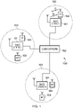
- Figure 1 provides a schematic diagram illustrating some basic functionality of a mobile telecommunications network / system 100 operating in accordance with LTE principles and which may be adapted to implement embodiments of the disclosure as described further below.
- Various elements of Figure 1 and their respective modes of operation are well-known and defined in the relevant standards administered by the 3GPP (RTM) body, and also described in many books on the subject, for example, Holma H. and Toskala A [2]. It will be appreciated that operational aspects of the telecommunications network which are not specifically described below may be implemented in accordance with any known techniques, for example according to the relevant standards.
- the network 100 includes a plurality of base stations 101 connected to a core network 102.
- Each base station provides a coverage area 103 (i.e. a cell) within which data can be communicated to and from terminal devices 104.
- Data is transmitted from base stations 101 to terminal devices 104 within their respective coverage areas 103 via a radio downlink.
- Data is transmitted from terminal devices 104 to the base stations 101 via a radio uplink.
- the core network 102 routes data to and from the terminal devices 104 via the respective base stations 101 and provides functions such as authentication, mobility management, charging and so on.
- Terminal devices may also be referred to as mobile stations, user equipment (UE), user terminal, mobile radio, communications device, and so forth.
- Base stations which are an example of network infrastructure equipment, may also be referred to as transceiver stations / nodeBs / e-nodeBs, and so forth.
- FIG. 2 shows a schematic diagram illustrating an OFDM based LTE downlink radio frame 201.
- the LTE downlink radio frame is transmitted from a LTE base station (known as an enhanced Node B) and lasts 10 ms.
- the downlink radio frame comprises ten subframes, each subframe lasting 1 ms.
- a primary synchronisation signal (PSS) and a secondary synchronisation signal (SSS) are transmitted in the first and sixth subframes of the LTE frame.
- a physical broadcast channel (PBCH) is transmitted in the first subframe of the LTE frame.
- PSS primary synchronisation signal
- SSS secondary synchronisation signal
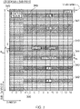
- Figure 3 is a schematic diagram of a grid which illustrates the structure of an example conventional downlink LTE subframe.
- the subframe comprises a predetermined number of symbols which are transmitted over a 1ms period.
- Each symbol comprises a predetermined number of orthogonal subcarriers distributed across the bandwidth of the downlink radio carrier.
- the example subframe shown in Figure 3 comprises 14 symbols and 1200 subcarriers spread across a 20MHz bandwidth licenced for use by the operator of the network 100, and this example is the first subframe in a frame (hence it contains PBCH).
- the smallest allocation of physical resource for transmission in LTE is a resource block comprising twelve subcarriers transmitted over one subframe.
- each individual resource element is not shown, instead each individual box in the subframe grid corresponds to twelve subcarriers transmitted on one symbol.
- Figure 3 shows in hatching resource allocations for four LTE terminals 340, 341, 342, 343.
- the resource allocation 342 for a first LTE terminal extends over five blocks of twelve subcarriers (i.e. 60 subcarriers)
- the resource allocation 343 for a second LTE terminal extends over six blocks of twelve subcarriers (i.e. 72 subcarriers), and so on.
- Control channel data can be transmitted in a control region 300 (indicated by dotted-shading in Figure 3 ) of the subframe comprising the first "n" symbols of the subframe where "n” can vary between one and three symbols for channel bandwidths of 3MHz or greater and where "n” can vary between two and four symbols for a channel bandwidth of 1.4MHz.
- the data transmitted in the control region 300 includes data transmitted on the physical downlink control channel (PDCCH), the physical control format indicator channel (PCFICH) and the physical HARQ indicator channel (PHICH). These channels transmit physical layer control information.
- PDCCH physical downlink control channel
- PCFICH physical control format indicator channel
- PHICH physical HARQ indicator channel
- Control channel data can also or alternatively be transmitted in a second region of the subframe comprising a number of subcarriers for a time substantially equivalent to the duration of the subframe, or substantially equivalent to the duration of the subframe remaining after the "n" symbols.
- the data transmitted in this second region is transmitted on the enhanced physical downlink control channel (EPDCCH).
- EPDCCH enhanced physical downlink control channel
- This channel transmits physical layer control information which may be in addition to that transmitted on other physical layer control channels.
- PDCCH and EPDCCH contain control data indicating which subcarriers of the subframe have been allocated to specific terminals (or all terminals or subset of terminals). This may be referred to as physical-layer control signalling / data.
- the PDCCH and / or EPDCCH data transmitted in the control region 300 of the subframe shown in Figure 3 would indicate that UE1 has been allocated the block of resources identified by reference numeral 342, that UE2 has been allocated the block of resources identified by reference numeral 343, and so on.
- PCFICH contains control data indicating the size of the control region (i.e. between one and three symbols for channel bandwidths of 3 MHz or greater and between two and four symbols for channel bandwidths of 1.4 MHz).
- PHICH contains HARQ (Hybrid Automatic Request) data indicating whether or not previously transmitted uplink data has been successfully received by the network.
- HARQ Hybrid Automatic Request
- Symbols in a central band 310 of the time-frequency resource grid are used for the transmission of information including the primary synchronisation signal (PSS), the secondary synchronisation signal (SSS) and the physical broadcast channel (PBCH).
- This central band 310 is typically 72 subcarriers wide (corresponding to a transmission bandwidth of 1.08 MHz).
- the PSS and SSS are synchronisation signals that once detected allow a LTE terminal device to achieve frame synchronisation and determine the physical layer cell identity of the enhanced Node B transmitting the downlink signal.
- the PBCH carries information about the cell, comprising a master information block (MIB) that includes parameters that LTE terminals use to properly access the cell.
- MIB master information block
- PDSCH Physical downlink shared channel
- RRC Radio Resource Control
- NAS Non Access Stratum
- the user-plane data and non-physical layer control-plane data conveyed on PDSCH may be referred to as higher layer data (i.e. data associated with a layer higher than the physical layer).
- Figure 3 also shows a region of PDSCH containing system information and extending over a bandwidth of R344.
- a conventional LTE subframe will also include reference signals which are not shown in Figure 3 in the interests of clarity.
- the number of subcarriers in a LTE channel can vary depending on the configuration of the transmission network. Typically this variation is from 72 sub carriers contained within a 1.4MHz channel bandwidth to 1200 subcarriers contained within a 20MHz channel bandwidth (as schematically shown in Figure 3 ). As is known in the art, data transmitted on the PDCCH, PCFICH and PHICH is typically distributed on the subcarriers across the entire bandwidth of the subframe to provide for frequency diversity.
- a terminal device in radio resource control (RRC) connected mode receives and decodes PDCCH in subframes to identify if there are any transmission resource allocations (resource grants) for the terminal device in the subframe.
- RRC radio resource control
- a terminal device is thus conventionally required to receive and decode PDCCH for all subframes in which the terminal device might potentially be allocated transmission resources, even though in many of these subframes there might not be any data for the terminal device.
- Resources used in receiving and decoding PDCCH in subframes for which there is no data for the terminal device are in effect wasted.
- a known technique for lowering power consumption in LTE-type terminals is to restrict the number of subframes for which a terminal device should monitor PDCCH using so-called discontinuous reception, DRX, techniques.
- DRX techniques involve a terminal device and a base station in effect agreeing times (e.g. particular subframes) during which the terminal device will be monitoring downlink physical channels and the base station can expect the terminal device to receive transmissions sent to it.
- the terminal device thus knows that outside these agreed times there are subframes when it will not receive transmissions from the base station, and the terminal device may conserve power during these subframes by not receiving and decoding PDCCH.
- a DRX mode comprises alternating periods during which a terminal device could potentially receive data from the base station (and hence should monitor PDCCH) and periods during which the terminal device will not receive data (and hence need not monitor PDCCH to save power).
- the subframes in which the terminal device could receive data from the base station may be referred to as DRX inactive periods and the subframes in which the terminal device should not receive data from the base station may be referred to a DRX active periods.
- DRX inactive periods may also be referred to as wake periods or non-dormant periods and DRX active periods may also be referred to sleep periods or dormant periods.
- waking-up The process of transitioning from a DRX active (sleep / dormant) mode of operation to a DRX inactive (wake / non-dormant) mode of operation may be referred to as waking-up.
- a terminal device operating in a DRX inactive mode may be referred to as being awake and a terminal device operating in a DRX active mode may be referred to as being asleep.
- DRX inactive periods and DRX active periods are defined by various parameters (which may be defined in terms of numbers of subframes).
- DRX parameters There are six basic DRX parameters that define the pattern of DRX inactive and DRX active periods in LTE (i.e. the times of transitions between these two DRX operating modes). These are:
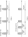
- FIGS 4 to 7 are schematic diagrams showing how the above-identified DRX parameters are defined on a representative time axis t. (The timings in these figures are represented for clarity of explanation and are not necessarily shown to scale.)
- Figure 4 schematically represents the basic underlying DRX cycle with periods when the terminal device receiver circuitry is active (awake) and monitoring PDCCH (DRX inactive mode) schematically represented by diagonally shaded blocks on the time axis t.
- This aspect of the LTE DRX mode may be referred to herein as the "normal” or “basic" DRX cycle / mode.
- the timings relating to this normal DRX cycle are set by the parameters DRX Cycle and On Duration Timer as schematically represented in the figure.
- a terminal device activates its receiver circuitry and monitors PDCCH for a period corresponding to On Duration Timer once every DRX Cycle.
- a relatively long basic DRX cycle allows for more power to be conserved.
- a long basic DRX cycle also results in increased latency because there are longer periods of time during which the terminal device is not monitoring PDCCH (and hence cannot be contacted).
- the short DRX cycle is broadly similar to the normal DRX cycle in overall structure in that it also comprises a regular pattern of DRX inactive and DRX active periods.
- the short DRX cycle adopts a shorter repeat period.
- the operation of the short DRX cycle is governed by the parameters DRX Short Cycle and DRX Short Cycle Timer.
- DRX Short Cycle is the repeat period for the short DRX cycle (DRX Cycle is an integer multiple of DRX Short Cycle in LTE).
- DRX Short Cycle timer defines the number of short DRX cycle periods before the normal DRX cycle is entered. (In LTE the On Duration Timer applies for both short and normal DRX cycles.)
- a terminal device which has concluded communicating with a network follows the short DRX cycle mode of operation before entering the longer / normal DRX cycle mode (assuming no communications are made during the period established by DRX Short cycle Timer).
- the principle underlying this approach in LTE is a recognition that a terminal device is more likely to need to re-communicate with a network relatively soon after a previous communication, and so a shorter DRX cycle can be used to reduce latency for a period after a recent communication. If, however, the terminal device does not re-communicate with the base station during this period, the terminal device may then drop into the longer normal DRX cycle.
- Figure 5 schematically represents some aspects of the short DRX cycle in LTE.
- Figure 5 is similar to, and will be understood from, Figure 4 , except the left-most DRX cycle in Figure 4 is replaced in Figure 5 with a section of short DRX cycle mode.
- the DRX Short Cycle is one-half the normal DRX Cycle.
- the DRX Short Cycle Timer in this particular timing example is taken to expire at the end of the second DRX Short Cycle represented in Figure 5 such that the normal (longer) DRX cycle, as represented in Figure 4 , picks up from this point.
- the DRX mode comprises a number of short cycles followed by a longer DRX opportunity until the next DRX cycle begins.
- LTE defines various non-repeating / irregular DRX inactive periods during which a terminal device is required to monitor PDCCH, and these are schematically represented in Figure 6 .
- the upper part of Figure 6 is a timeline representing various periods during which a terminal device receiver is active while the lower part of Figure 6 is a corresponding timeline representing periods during which the terminal device transmitter is active.
- Figure 6 uses blocks to identify times at which the terminal device is required to monitor PDCCH.
- the terminal device In the left-most DRX inactive period represented in Figure 6 (i.e. the earliest period), the terminal device receives a downlink communication on PDSCH. This may be any conventional downlink communication and is indicated in the figure by a solid line labelled PDSCH allocation.
- the receipt of a downlink communication initiates a timer during which a terminal device is required to continue monitoring PDCCH, even if the On Duration Timer associated with the normal regular and repeating DRX cycle expires.
- This timer is set by the DRX Inactivity Timer parameter.
- the DRX Inactivity Timer causes the DRX inactive period during which the terminal device must monitor PDCCH to be extended beyond the "normal" DRX inactive period if a downlink communication is received during the "normal" DRX inactive period. This is schematically represented by the square grid shading in Figure 6 for the leftmost DRX inactive period.
- the DRX Inactivity Timer is reset, thereby extending the DRX inactive period further still. Only once the DRX Inactivity Timer expires can the terminal device re-enter DRX active mode.
- the terminal device In response to the PDSCH allocation represented in the left-most DRX inactive period in the upper part of Figure 6 , the terminal device will, in accordance with conventional techniques, transmit uplink acknowledgement signalling (ACK/NACK signalling) for this (schematically represented in the lower part of Figure 6 by the chequer-board shaded block).
- ACK/NACK signalling uplink acknowledgement signalling
- the terminal device sends its acknowledgement signalling four subframes after the subframe containing the relevant PDSCH allocation. If the terminal device is unable to properly decode the PDSCH allocation it will transmit negative acknowledgement (NACK) signalling.
- NACK negative acknowledgement
- the base station schedules a retransmission of the information comprising the PDCCH allocation.
- the base station has some flexibility with regards to rescheduling the retransmission.
- the base station cannot reschedule the transmission before a time set by HARQ RTT Timer (e.g. eight subframes) after the initial PDSCH allocation has expired, but the base station does not need to schedule the retransmission in the subframe immediately after HARQ RTT Timer expires.
- HARQ RTT Timer e.g. eight subframes
- a terminal device if a terminal device cannot properly decode a PDSCH allocation and transmits corresponding negative acknowledgement signalling, the terminal device must reactivate its receiver circuitry when HARQ RTT Timer expires in the expectation that the base station will at some stage after HARQ RTT Timer expires schedule a retransmission of the information sent in the previous PDSCH allocation.
- the parameter DRX Retransmission Timer specifies the amount of time the terminal device must remain active after expiry of HARQ RTT Timer to monitor PDCCH for a resource allocation for a retransmission of the earlier PDSCH allocation that was negatively acknowledged. This period of time during which the terminal device cannot remain in DRX active mode is schematically resented in Figure 6 by the block with dotted shading.
- a retransmission of a previous negatively-acknowledged PDSCH allocation may be expected to occur during the period corresponding to the DRX Retransmission Timer, and this will require the terminal device to remain in an active mode monitoring PDCCH waiting for the retransmission to be received on PDSCH or for the DRX Retransmission Timer to expire.
- Figure 6 represents how the repeating and regular pattern of active and inactive DRX periods of Figures 4 and 5 becomes disrupted when a terminal device receives downlink communications and how this result in additional periods of time during which the terminal device must monitor PDCCH.
- the right-hand half of Figure 6 represents another situation which results in a terminal device needing to monitor PDCCH outside the repeating and regular pattern of active and inactive DRX periods such as represented in Figures 4 and 5 .
- This is triggered by the terminal device making a scheduling request (SR) with an uplink transmission on the physical uplink control channel (PUCCH).
- SR scheduling request
- PUCCH physical uplink control channel
- a terminal device will typically do this when it wishes to request uplink resources because the terminal device has data it needs to communicate to the network.
- the PDCCH SR is schematically represented in the lower part of Figure 6 by the brick-shaded block.
- a terminal device When a terminal device transmits a SR on PUCCH it can expect to receive a response from the base station on PDSCH. In order to receive the response, the terminal device must therefore monitor PDCCH for the PDSCH allocation message. That is to say, on sending the PUCCH SR, the terminal device must exit DRX active mode. This is schematically represented in Figure 6 by the by the block with zigzag shading. Once the terminal device receives the PDSCH allocation in response to the PUCCH SR, the DRX Inactivity Timer is restarted as discussed above, and as schematically represented in the right-hand part of the upper timeline in Figure 6 .
- Figure 6 represents how the repeating and regular pattern of active and inactive DRX periods of Figures 4 and 5 also becomes disrupted when a terminal device requests uplink resources and how this again results in additional periods of time during which the terminal device must monitor PDCCH.
- the parameters DRX Cycle, On Duration Timer, DRX Short Cycle, DRX Short Cycle Timer, DRX Inactivity Timer, and DRX Retransmission Timer which define the DRX timings are shared between the base station and terminal device through RRC signalling in accordance with conventional techniques.
- the starting point of the DRX cycle i.e. what might be termed its phase relative to the system frame numbering
- DRX Start Offset which is communicated through RRC signalling.
- both the terminal device and the network can determine from the system frame number the particular subframes when the terminal device receiver should be active and listening to PDCCH. This allows the base station to schedule transmissions to the base station at the appropriate times and the terminal device to activate its receiver circuitry to receive any such transmissions at the appropriate times.
- the DRX opportunities i.e. the times in which the terminal device need not monitor PDCCH - the DRX active periods
- the basic DRX cycle would suggest.
- Figure 6 shows a significant increase in the amount of time during which the terminal device must monitor PDCCH (i.e. the periods represented by the grid, dot and zigzag shaded blocks) over and above the times during which the terminal device must monitor PDCCH in accordance with the basic regular and repeating DRX cycles (i.e. the periods represented by the diagonal shaded blocks).
- the extended DRX mode may operate on longer cycle times than the short/long cycle DRX procedures in LTE and place the terminal device into an even lower power mode than the current DRX active mode (sleep mode).
- the extended DRX (eDRX) mode may be conveniently referred to as a deep sleep mode. It has been proposed a terminal device in an RRC connected state and which supports the eDRX mode may transition to eDRX active mode (deep sleep) from the DRX inactive mode (awake) in response to an explicit eDRX command and may transition to eDRX active mode (deep sleep) from the DRX active mode (sleep) in response to either an explicit eDRX command or expiry of an eDRX Timer.
- a terminal device when a terminal device finishes transmitting data to a network it cannot enter a sleep mode (reduced power mode) until it receives a communication from the network instructing the terminal device to transition to the (deep) sleep mode, for example as proposed in WO 2014/024175 [6] or until an associated timer expires.
- the inventors have recognised for certain types of terminal device, such as, although not exclusively, MTC-type devices, the power costs associated with operating unnecessarily in a DRX inactive mode (i.e. awake) can represent a relatively significant increase in their power consumption.
- a particular example MTC-type device might be expected to operate with its transceiver circuitry activated for only a second or so a day.
- any saving in the time during which the device remains awake i.e. In DRX inactive mode
- certain embodiments of the disclosure are directed to increasing the time during which a terminal device may operate in a sleep / reduced-power mode.
- FIG. 7 schematically shows a telecommunications system 500 according to an embodiment of the present disclosure.
- the telecommunications system 500 in this example is based broadly around an LTE-type architecture. As such many aspects of the operation of the telecommunications system 500 are known and understood and are not described here in detail in the interest of brevity. Operational aspects of the telecommunications system 500 which are not specifically described herein may be implemented in accordance with any known techniques, for example according to the current LTE-standards.
- the telecommunications system 500 comprises a core network part (evolved packet core) 502 coupled to a radio network part.
- the radio network part comprises a base station (evolved-nodeB) 504 coupled to a plurality of terminal devices.
- a base station evolved-nodeB
- two terminal devices are shown, namely a first terminal device 506 and a second terminal device 508.
- the radio network part may comprise a plurality of base stations serving a larger number of terminal devices across various communication cells. However, only a single base station and two terminal devices are shown in Figure 7 in the interests of simplicity.
- the terminal devices 506, 508 are arranged to communicate data to and from the base station (transceiver station) 504.
- the base station is in turn communicatively connected to a serving gateway, S-GW, (not shown) in the core network part which is arranged to perform routing and management of mobile communications services to the terminal devices in the telecommunications system 500 via the base station 504.
- S-GW serving gateway
- the core network part 502 also includes a mobility management entity (not shown) which manages the enhanced packet service, EPS, connections with the terminal devices 506, 508 operating in the communications system based on subscriber information stored in a home subscriber server, HSS.
- EPS enhanced packet service
- PCRF policy charging and resource function
- PDN-GW packet data network gateway
- the first terminal device 506 is a conventional smartphone type terminal device communicating with the base station 504 in a conventional manner.
- This conventional terminal device 506 comprises a transceiver unit 506a for transmission and reception of wireless signals and a processor unit 506b configured to control the device 506.
- the processor unit 506b may comprise a processor unit which is suitably configured / programmed to provide the desired functionality using conventional programming / configuration techniques for equipment in wireless telecommunications systems.
- the transceiver unit 506a and the processor unit 506b are schematically shown in Figure 7 as separate elements.
- the functionality of these units can be provided in various different ways, for example using a single suitably programmed general purpose computer, or suitably configured application-specific integrated circuit(s) / circuitry.
- the conventional terminal device 506 will in general comprise various other elements associated with its operating functionality.
- the second terminal device 508 is a machine-type communication (MTC) terminal device 504 adapted to support operation in accordance with embodiments of the present disclosure when communicating with the base station 504.
- machine-type communication terminal devices can in some cases be typically characterised as semi-autonomous or autonomous wireless communication devices communicating small amounts of data. Examples include so-called smart meters which, for example, may be located in a customer's house and periodically transmit information back to a central MTC server data relating to the customer's consumption of a utility such as gas, water, electricity and so on.
- MTC devices may in some respects be seen as devices which can be supported by relatively low bandwidth communication channels having relatively low quality of service (QoS), for example in terms of latency. It is assumed here the MTC terminal device 508 in Figure 7 is such a device.
- QoS quality of service
- the MTC device 508 comprises a transceiver unit 508a for transmission and reception of wireless signals and a processor unit 508b configured to control the MTC device 508.
- the processor unit 508b may comprise various sub-units, for example a DRX control unit, for providing functionality in accordance with embodiments of the present disclosure as explained further herein. These sub-units may be implemented as discrete hardware elements or as appropriately configured functions of the processor unit.
- the processor unit 508b may comprise a processor unit which is suitably configured / programmed to provide the desired functionality described herein using conventional programming / configuration techniques for equipment in wireless telecommunications systems.
- the transceiver unit 508a and the processor unit 508b are schematically shown in Figure 7 as separate elements for ease of representation.
- the functionality of these units can be provided in various different ways, for example using a single suitably programmed general purpose computer, or suitably configured application-specific integrated circuit(s) / circuitry. It will be appreciated the MTC device 508 will in general comprise various other elements associated with its operating functionality.
- the base station 504 comprises a transceiver unit 504a for transmission and reception of wireless signals and a processor unit 504b configured to control the base station 504 to operate in accordance with embodiments of the present disclosure as described herein.
- the processor unit 506b may again comprise various sub-units, such as a scheduling unit, for providing functionality in accordance with embodiments of the present disclosure as explained further below. These sub-units may be implemented as discrete hardware elements or as appropriately configured functions of the processor unit.
- the processor unit 504b may comprise a processor unit which is suitably configured / programmed to provide the desired functionality described herein using conventional programming / configuration techniques for equipment in wireless telecommunications systems.
- transceiver unit 504a and the processor unit 504b are schematically shown in Figure 7 as separate elements for ease of representation. However, it will be appreciated that the functionality of these units can be provided in various different ways, for example using a single suitably programmed general purpose computer, or suitably configured application-specific integrated circuit(s) / circuitry. It will be appreciated the base station 504 will in general comprise various other elements associated with its operating functionality.
- the base station 504 is configured to communicate data with both the conventional terminal device 506 and the terminal device 508 according to an embodiment of the disclosure over respective communication links 510, 512.
- the base station 504 is configured to communicate with the conventional terminal device 506 over the associated radio communication link 510 following the established principles of LTE-based communications, and in particular using conventional DRX procedures.
- communications between the base station 504 and the MTC terminal device 508 operate using modified DRX procedures in accordance with certain embodiments of the present disclosure as described herein.
- the base station is configured to operate by communicating with different classes of terminal device (e.g.
- a base station may operate to communicate with a first class (group / type) of terminal device in accordance with a first DRX mode (e.g. in accordance with conventional DRX procedures) and to communicate with a second class (group / type) of terminal device in accordance with a second DRX mode (e.g. in accordance with modified procedures such as described herein).
- Whether or not a particular terminal device or base station supports modified DRX procedures in accordance with embodiments of the present disclosure may be established in accordance with conventional techniques for sharing terminal device and base station capability information in wireless telecommunications networks, for example based on signalling exchange during a RRC connection establishment procedure.
- the base station communicates with the first class of terminal device, e.g. the terminal device 506, using conventional DRX procedures, for example, following the principles schematically represented in Figures 4 to 7 .
- the base station communicates with the second class of terminal device, e.g. the MTC terminal device 508, using modified procedures as described herein to help increase the amount of time the MTC terminal device can operate in the DRX active / reduced power mode.
- a first and a second entity may operate in a wireless telecommunications network to exchange a block of data.
- the first entity is operable to switch between a first operating mode (e.g. an awake mode / a DRX inactive mode / a connected mode) and a second operating mode (e.g. a sleep mode / a DRX active mode / an idle mode), wherein the second operating mode is a reduced-power mode as compared to the first operating mode.
- the first entity is operable to exchange the block of data with the second entity (e.g.
- the second entity is configured to assume the first entity has switched to the second operating mode in response to determining communications associated with the exchange of the block of data are complete, and to take account of this for any further communications (for example by taking account of when the first terminal device will next exit the second operating mode, for example according to a predefined timing schedule, before attempting to contact the first entity for further communications.
- Figure 8 schematically shows some aspects of a user-plane protocol stack for the terminal device 508 and base station 504 for the LTE-based wireless telecommunications network 500 represented in Figure 7 .
- the protocol stack in this implementation comprises a physical layer, PHY, a medium access control layer, MAC, a radio link control layer, RLC, and a Packet Data Convergence Protocol layer, PDCP.
- the PDCP layer supports efficient transport of IP packets over the radio link. It performs header compression, Access Stratum (AS) security (ciphering and integrity protection) and packet re-ordering/retransmission during handover.
- AS Access Stratum
- the RLC layer on the transmitting side constructs RLC PDUs (protocol data units) and provides the RLC PDUs to the MAC layer.
- the RLC layer also performs packet re-ordering.
- the RLC protocol also performs segmentation/concatenation of PDCP PDUs where appropriate.
- the RLC protocol performs reassembly of the RLC PDUs.
- the RLC protocol has three operational modes, namely transparent mode (TM), acknowledged mode (AM) and unacknowledged mode (UM).
- RLC transparent mode PDUs pass the RLC layer without any modification and there is no RLC layer acknowledgement procedure.
- UM RLC unacknowledged mode
- SDUs service data units
- RLC acknowledged mode AM is similar to the unacknowledged mode, but also supports RLC layer implemented automatic repeat request (ARQ) acknowledgement procedures.
- RLC AM is a selective-repeat ARQ procedure, which means that only PDUs which are missing (NACKd) are retransmitted, and unlike a stop-and-wait (SAW) procedure, the ARQ procedure allows for further transmissions without waiting for ACK / NACK.
- SAW stop-and-wait
- LTE-based RLC-implemented acknowledgement procedures can be found, for example, in ETSI TS 136 322 V12.2.0 (2015-04) / 3GPP TS 36.322 version 12.2.0 Release 12 [7].
- One aspect of such procedures is that a poll bit is set in the header of an RLC data PDU when there is no more data for transmission, e.g.
- the poll bit in the header of an RLC data unit indicates the data unit is the last data unit in a current group of data units comprising a block of data being transmitted.
- the setting of a poll bit in the header of a PDU will typically indicate the associated PDU is the final PDU of a single SDU.
- a poll bit would typically be set on the final PDU, and a single acknowledgement would be received indicating whether or not the transmission was successful. If any PDU comprising the SDU is NACKed, then that (those) PDU (PDUs) would be retransmitted.
- RLC headers for a PDU comprise a framing information field which indicates whether or not the PDU contains the first and / or last byte of data from an SDU.
- the framing information in effect also provide an indication of whether a PDU is the last PDU for a block of data.
- the MAC layer lies between the RLC layer and PHY layer. It is connected to the RLC layer through logical channels, and to the PHY layer through transport channels, thus the MAC protocol supports multiplexing and de-multiplexing between logical channels and transport channels. Higher layers use different logical channels for different QoS (quality of service) metrics.
- the MAC protocol supports QoS by scheduling and prioritizing data from logical channels.
- the base station operates to ensure radio resources are dynamically allocated to terminal devices and performs QoS control to ensure each bearer is allocated the negotiated QoS.
- the MAC layer also supports hybrid automatic repeat request (HARQ) operations.
- HARQ hybrid automatic repeat request
- the PHY layer provides the radio interface between communicating entities.
- eDRX enhanced DRX
- NB-loT narrowband Internet of Things
- LTE-based Telecom application systems may include a new physical channel which might not be FDMA on uplink or which might, for example, use FDMA with GMSK (Gaussian minimum shift keying) modulation.
- GMSK Gausian minimum shift keying
- Figure 9 is ladder diagram indicating signalling between the terminal device 508 and the base station 504 represented in Figure 7 in accordance with an embodiment of the disclosure.
- This particular implementation assumes an RLC unacknowledged mode of operation is being used to transmit data from the terminal device to the base station while the terminal device is in a DRX inactive mode (awake) in accordance with conventional techniques.
- the terminal device 508 has a block of data (e.g. an SDU) which is segmented into a plurality of PDUs.
- the SDU i.e. the block of data to be transmitted
- the block of data may comprise only one data unit or more than two data units.
- that data unit may be considered the last data unit (last PDU).
- all the data units apart from the last data unit may in effect be handled in the same way as the first PDU.
- the RLC layer and MAC layer for each of the terminal device 508 and the base station 504 are schematically represented in Figure 9 .
- the other layers are not shown for simplicity.
- the UE RLC layer forwards a PDU to the UE MAC layer for transmission to the base station.
- the UE MAC layer transmits this data unit to the base station MAC layer via the physical layer (not shown in Figure 9 for simplicity).
- the base station MAC layer successfully receives the PDU and forwards it onto the base station RLC layer and sends positive MAC layer acknowledgement signalling (ACK) back to the UE MAC layer.
- the UE RLC layer forwards the next (which in this case is the last) PDU to the UE MAC layer for transmission is to the base station.
- the base station MAC layer is assumed to fail to successfully receive the final PDU and sends negative MAC layer HARQ acknowledgement signalling (NACK) back to the UE MAC layer.
- the UE MAC layer responds by retransmitting the last PDU to the base station.
- the base station MAC layer successfully receives the retransmitted last PDU and forwards it onto the base station RLC layer and sends positive MAC layer acknowledgement signalling (ACK) back to the UE MAC layer.
- ACK positive MAC layer acknowledgement signalling
- the terminal device 508 is configured to recognise when communications associated with the exchange of the block of data are complete (e.g. when it has received positive MAC layer acknowledgement signalling in respect of the last PDU), and to switch to a reduced-power mode of operation (e.g. a DRX active mode) in response to this.
- a reduced-power mode of operation e.g. a DRX active mode
- the terminal device can determine which is the last PDU to be transmitted for a given block of data. For example, this may be based on the terminal device determining that its transmission buffers are empty or based on framing information in an RLC header for a PDU indicating the PDU contains the last byte of an SDU.
- the RLC layer can thus indicate to the MAC layer, e.g. using the RLC header or separate signalling, which is the last PDU, so the MAC layer knows to trigger the transition to the reduced-power mode when the MAC layer HARQ procedure indicates positive acknowledgement signalling in respect of this PDU.
- the MAC layer itself may be configured to inspect the headers of the PDUs to identify when the last PDU is transmitted. However, this may in some implementations be considered undesirable because it does not fully align with the usual practices associated with inter-layer operations.
- this procedure is driven by the MAC layer.
- other transitions which may occur in accordance with the other implementations, for example from a connected mode to an idle mode, may be controlled by other layers, for example the RRC layer.
- the completion of signalling associated with the transfer of the block of data may be reported to the relevant layer to initiate the transition.
- Figure 10 is similar to, and will be answered from, Figure 9 , but shows a corresponding scenario in which the MAC layer HARQ procedure in respect of the last PDU fails, for example because successful acknowledgement signalling is not received after a threshold number of HARQ retransmissions.
- the UE MAC layer reports the MAC layer HARQ fail up to the UE RLC layer.
- the UE RLC layer may then initiate a retransmission (retx) of the last PDU.
- retx retransmission
- the base station knows when the base station MAC layer transmits positive HARQ acknowledgement signalling in respect of the last PDU received from the terminal device, and so can assume the terminal device has transitioned to the reduced-power mode, and tailor its subsequent operations accordingly.
- the reduced-power mode is a DRX active mode
- the base station may be configured to wait until the terminal device will next transition to the DRX inactive mode (i.e. wake-up) before seeking to establish contact with the terminal device, for example to undertake further communications.
- a subsequent cycle of wake and sleep periods may be established in accordance with conventional techniques (e.g. based on conventional DRX timers as discussed above).
- the approach represented in Figures 9 and 10 focuses on an RLC unacknowledged mode of operation, broadly the same principles can be applied for an RLC transparent mode of operation.
- the RLC layer may be configured to indicate the end of the transmission of the block of data to the MAC layer by using of a dedicated indicator for this purpose.
- Figure 11 is similar to, and will be understood from, Figures 9 and 10 . However, whereas Figures 9 and 10 show examples for an RLC unacknowledged mode of operation, Figure 11 shows an example implementation in accordance with an embodiment of disclosure using an RLC acknowledged mode (AM) of operation.
- AM RLC acknowledged mode
- an SDU comprising a block of data to be exchanged between the terminal device 508 and the base station 504 (which in this case is uplink data transmitted from the terminal device to the base station) is segmented into three PDUs at the UE RLC layer.
- the polling bit in the header of the last PDU is set to indicate it is the last PDU in accordance with conventional techniques (schematically shown as an "X" in the figure).
- the transmissions of the respective PDUs between the respective MAC layers will be associated with MAC HARQ signalling of the kind represented in Figure 9 and 10 in the usual way.
- the base station RLC layer On receiving the last PDU (i.e. the PDU with the poll bit set in its header), the base station RLC layer responds to detecting the poll bit by sending RLC layer acknowledgement signalling back to the UE RLC layer (via the other layers in the usual way). This is schematically represented in the figure by the signalling indicated by the label "ACK".
- the terminal device On receiving the positive acknowledgement signalling from the base station, the terminal device recognises that communications associated with the transfer of the block of data (i.e. the SDU) are complete, and the terminal device may transition to the reduced-power mode (e.g. a DRX active mode or an RRC idle mode depending on the specific reduced-power operating mode in respect of which the method is implemented).
- the reduced-power mode e.g. a DRX active mode or an RRC idle mode depending on the specific reduced-power operating mode in respect of which the method is implemented.
- the base station recognises it will cause the terminal device to automatically switch to the reduced-power mode, and the base station can act accordingly (i.e. treat the terminal device as having transitioned to the reduced power mode when determining how to undertake further communications with the terminal device, for example in terms of establishing timings for when the terminal device will be next awake and able to receive signalling).
- the base station may wait for MAC layer HARQ positive acknowledgement signalling in respect of the ACK signalling send in response to detection of the poll bit before assuming the terminal device has transitioned to the reduced-power state.
- the example of Figure 11 is shown in respect of uplink signalling, i.e. data transmission from the terminal device to the base station, it will be appreciated the same principles apply in respect of downlink signalling.
- the SDU will be segmented at the base station RLC layer and received at the terminal device RLC layer.
- the terminal device may send acknowledgement signalling back to the base station and then transition to the reduced-power mode.
- the base station on receiving the acknowledgement signalling, may then assume the terminal device has made the transition, and again act accordingly in respect of future operations vis-à-vis the terminal device.
- the terminal device may be configured to determine when communications associated with downlink data (i.e. data transmitted from the base station to the terminal device) are complete, and transition to the low power mode in response to this.
- the timing of the transition to the low-power mode may be based on when the terminal device has received MAC layer HARQ positive acknowledgement signalling in respect of an uplink status reports sent in response to the detection of a poll bit.
- the eNB implementation is designed to explicitly insert a MAC control element that instructs the UE to go into DRX state. From a UE perspective, this approach is less desirable since the UE cannot rely on the eNB implementing this functionality. Hence the UE needs to be designed to handle the case where the eNB does not implement this functionality (e.g. the UE battery needs to be dimensioned assuming the UE needs to apply DRX timers).
- the poll bit is set by the base station and the successful STATUS report (RLC layer acknowledgement signalling) is generated by the terminal device .
- the sending of the STATUS report may, for example, be considered complete once the MAC/L1 procedure has completed (i.e. HARQ ACK is received).
- Figure 12 is similar to, and will be generally understood from, Figure 11 , but shows a variation on that approach whereby the entity receiving the block of data being exchanged (i.e. the base station in the example of Figure 12 ) has a mechanism for indicating to the transmitting entity (i.e. the terminal device in the example of Figure 12 ) that it has its own data to transfer back to the other entity, and so the other entity should avoid entering the reduced power mode.
- the entity receiving the block of data being exchanged i.e. the base station in the example of Figure 12
- the transmitting entity i.e. the terminal device in the example of Figure 12
- One approach by which the receiving entity can prevent the transmitting entity from entering the reduced power mode is to simply delay acknowledging the receipt of the data from the transmitting entity until it has initiated its own transmissions back to the transmitting entity.
- the upper half of Figure 12 i.e. down as far as the transmission of the third (last) PDU from the UE to the base station, is the same as for Figure 11 .
- the higher layers at the base station generate a response which is to be transmitted back to the terminal device.
- the response data comprises an SDU which is segmented at the base station into two PDUs, as schematically indicated in the figure.
- SDU block of downlink data
- the base station may be configured to provide an explicit indication, for example through bespoke signalling, to indicate the terminal device should not transition to the reduced power mode.
- a terminal device may transition to a reduced power mode more quickly than with conventional techniques, and in particular it may do this without having to wait for any timer to expire, or having to wait for explicit signalling from the base station to indicate it should transition to the reduced power state.
- the same principles can be applied regardless of whether the terminal device is transmitting data to the base station, or whether the base station is transmitting data to the terminal device.
- the terminal device is configured to determine when communications associated with the exchange of a block of data with the base station are complete, and to transition into the low-power mode in response to this.
- the base station is also configured to determine when communications associated with the exchange of a block of data with the terminal device are complete, and to assume the terminal device will transition into the low-power mode in response to this.
- a UE enters DRX upon completion of data transmission or reception without using inactivity timer or explicit DRX command in MAC.
- AM RLC poll bit is set upon transmission of the last PDU in the buffer - for small data applications this will often be the last PDU of a single RLC SDU.
- UE can enter DRX when the poll bit is received.
- UE may be configured to enter DRX when the RLC ACK is received in response to setting poll bit in the last PDU transmitted in the uplink.
- UE may be configured to automatically enter DRX upon transmission of last PDU in buffer.
- the same principles can be adopted in respect of transitions between other pairs of modes where one mode is a reduced-power mode as compared to the other.
- the same principles can be applied in respect of transitions from a radio resource connected, RRC, control mode to a radio resource control, RRC, idle mode and / or from a radio resource connected, RRC, control mode to a radio resource control, RRC, suspended mode.
- the non-reduced-power operating mode may be a mode in which the terminal device is configured to monitor a downlink control channel (e.g. PDCCH in LTE) for radio resource allocation signalling from the base station and the reduced-power operating mode may be a mode in which the terminal device is configured to not monitor the downlink control channel for the radio resource allocation signalling from the base station.
- a downlink control channel e.g. PDCCH in LTE
- a base station executing methods in accordance with embodiments of the disclosure as described herein in respect of its communications with certain terminal devices may also be communicating with other terminal devices in the network in accordance with conventional techniques.
- a base station may communicate with some terminal devices in accordance with embodiments of the disclosure described herein and other terminal devices that
- a base station of the wireless telecommunications system is providing functionality in accordance with the principles described herein
- similar functionality may be provided by other components of the wireless telecommunications network infrastructure.
- some, or all, of the processing described above in relation to the base station may be provided by a core network component of the wireless telecommunications system and / or similar functionality may be provided by other infrastructure elements, such as relay nodes and / or dedicated units for supporting an ITS scheme, for example roadside units (RSUs) deployed in association with a road network to facilitate vehicle-to-vehicle communications in accordance with previously proposed schemes.
- RSUs roadside units
- a base station may be considered as one example of network infrastructure equipment and maybe configured to provide functionality of the kind described herein.
- a method of operating a terminal device in a wireless telecommunications system wherein the terminal device is configured to selectively switch between an active operating mode and a reduced-power operating mode
- the method comprises: communicating with a network entity to exchange a block of data between the terminal device and the network entity while the terminal device is in the active operating mode; determining when communications associated with the exchange of the block of data are complete; and in response to determining communications associated with the exchange of the block of data are complete, switching from the active operating mode to the reduced-power operating mode.
- the terminal device supports a protocol stack comprising a physical, PHY, layer, a medium access control, MAC, layer, and a radio link control, RLC, layer, and determining when communications associated with the exchange of the block of data are complete and the device should switch to the low-power mode is performed by the radio link control, RLC, layer.
Landscapes
- Engineering & Computer Science (AREA)
- Computer Networks & Wireless Communication (AREA)
- Signal Processing (AREA)
- Mobile Radio Communication Systems (AREA)
Claims (14)
- Verfahren zum Betreiben eines Endgeräts (508) in einem drahtlosen Telekommunikationssystem (500), wobei das Endgerät konfiguriert ist, um selektiv zwischen einem aktiven Betriebsmodus und einem leistungsreduzierten Betriebsmodus umzuschalten, wobei das Verfahren Folgendes umfasst:Kommunizieren mit einer Netzkomponente (504) zum Austauschen eines Datenblocks zwischen dem Endgerät und der Netzkomponente, während das Endgerät im aktiven Betriebsmodus ist;Bestimmen, wann mit dem Austausch des Datenblocks assoziierte Kommunikationen beendet sind; undals Reaktion auf das Bestimmen, dass mit dem Austausch des Datenblocks assoziierte Kommunikationen beendet sind, Umschalten aus dem aktiven Betriebsmodus in den leistungsreduzierten Betriebsmodus;wobei das Endgerät einen Protokollstapel, der einen Physical Layer, PHY, einen Medium Access Control Layer, MAC, und einen Radio Link Control Layer, RLC, umfasst, unterstützt, dadurch gekennzeichnet, dass das Bestimmen, wann mit dem Austausch des Datenblocks assoziierte Kommunikationen beendet sind, am Radio Link Control Layer, RLC, durchgeführt wird.
- Verfahren nach Anspruch 1, wobei das Kommunizieren mit der Netzkomponente zum Austauschen des Datenblocks umfasst, dass der Datenblock vom Endgerät an die Netzkomponente übertragen wird, wobei der Datenblock einem Framing oder einer Segmentierung in eine oder mehrere Uplink-Dateneinheiten für die Übertragung vom Endgerät an die Netzkomponente unterzogen wird.
- Verfahren nach Anspruch 2, wobei das Bestimmen, wann mit dem Austausch des Datenblocks assoziierte Kommunikationen beendet sind, umfasst, dass bestimmt wird, wann die letzte der den Datenblock umfassenden Uplink-Dateneinheiten an die Netzkomponente übertragen worden ist, oder wobei das Bestimmen, wann mit dem Austausch des Datenblocks assoziierte Kommunikationen beendet sind, umfasst, dass bestimmt wird, wann eine Bestätigungssignalisierung von der Netzkomponente empfangen wird, die anzeigt, dass die letzte der den Datenblock umfassenden Uplink-Dateneinheiten, die an die Netzkomponente übertragen worden ist, erfolgreich durch die Netzkomponente empfangen worden ist.
- Verfahren nach Anspruch 2, das ferner umfasst, dass das Endgerät eine Anzeige zum Anzeigen, dass eine den Datenblock umfassende Uplink-Dateneinheit die letzte der den Datenblock umfassenden Uplink-Dateneinheiten zur Übertragung ist, an die Netzkomponente übermittelt.
- Verfahren nach Anspruch 4, wobei die jeweiligen den Datenblock umfassenden Uplink-Dateneinheiten mit einem Header für die Übertragung assoziiert sind und wobei der Header für die letzte der den Datenblock umfassenden Uplink-Dateneinheiten zur Übertragung die Anzeige umfasst.
- Verfahren nach Anspruch 2, das ferner umfasst, dass das Endgerät eine Anzeige von der Netzkomponente zum Anzeigen, dass das Endgerät das Umschalten in den leistungsreduzierten Betriebsmodus verzögern soll, nachdem die mit dem Austausch des Datenblocks assoziierten Kommunikationen beendet worden sind, empfängt.
- Verfahren nach Anspruch 1, wobei das Kommunizieren mit der Netzkomponente zum Austauschen des Datenblocks umfasst, dass das Endgerät den Datenblock von der Netzkomponente empfängt, wobei der Datenblock einer Segmentierung in eine oder mehrere Downlink-Dateneinheiten für die Übertragung von der Netzkomponente an das Endgerät unterzogen wird.
- Verfahren nach Anspruch 7, das ferner umfasst, dass das Endgerät durch Detektieren einer durch die Netzkomponente übertragenen Anzeige zum Anzeigen, dass eine assoziierte Downlink-Dateneinheit die letzte der den Datenblock umfassenden Downlink-Dateneinheiten zur Übertragung durch die Netzkomponente ist, bestimmt, dass eine Downlink-Dateneinheit die letzte der den Datenblock umfassenden Downlink-Dateneinheiten zur Übertragung durch die Netzkomponente ist.
- Verfahren nach Anspruch 1, das ferner umfasst, dass das Endgerät bestimmt, dass es das Umschalten in den leistungsreduzierten Betriebsmodus verzögern soll, nachdem die mit dem Austausch des Datenblocks assoziierten Kommunikationen beendet worden sind, weil das Endgerät an die Netzkomponente noch zu übertragende Uplink-Daten aufweist.
- Endgerät (508) zur Nutzung in einem drahtlosen Telekommunikationssystem (500), wobei das Endgerät konfiguriert ist, um selektiv zwischen einem aktiven Betriebsmodus und einem leistungsreduzierten Betriebsmodus umzuschalten, und wobei das Endgerät eine Controllereinheit (508b) und eine Transceivereinheit (508a) umfasst, die konfiguriert sind, um zusammen für Folgendes betrieben zu werden:Kommunizieren mit einer Netzkomponente zum Austauschen eines Datenblocks zwischen dem Endgerät und der Netzkomponente, während das Endgerät im aktiven Betriebsmodus ist;Bestimmen, wann mit dem Austausch des Datenblocks assoziierte Kommunikationen beendet sind; undals Reaktion auf das Bestimmen, dass mit dem Austausch des Datenblocks assoziierte Kommunikationen beendet sind, Umschalten aus dem aktiven Betriebsmodus in den leistungsreduzierten Betriebsmodus,wobei das Endgerät einen Protokollstapel, der einen Physical Layer, PHY, einen Medium Access Control Layer, MAC, und einen Radio Link Control Layer, RLC, umfasst, unterstützt, dadurch gekennzeichnet, dass das Bestimmen, wann mit dem Austausch des Datenblocks assoziierte Kommunikationen beendet sind, am Radio Link Control Layer, RLC, durchgeführt wird.
- Schaltungsanordnung für ein Endgerät (508) zur Nutzung in einem drahtlosen Telekommunikationssystem (500), wobei das Endgerät konfiguriert ist, um selektiv zwischen einem aktiven Betriebsmodus und einem leistungsreduzierten Betriebsmodus umzuschalten, wobei die Schaltungsanordnung ein Controllerelement (508b) und ein Transceiverelement (508a) umfasst, die konfiguriert sind, um zusammen für Folgendes betrieben zu werden:Kommunizieren mit einer Netzkomponente (504) zum Austauschen eines Datenblocks zwischen dem Endgerät und der Netzkomponente, während das Endgerät im aktiven Betriebsmodus ist;Bestimmen, wann mit dem Austausch des Datenblocks assoziierte Kommunikationen beendet sind; undals Reaktion auf das Bestimmen, dass mit dem Austausch des Datenblocks assoziierte Kommunikationen beendet sind, Umschalten aus dem aktiven Betriebsmodus in den leistungsreduzierten Betriebsmodus;wobei das Endgerät einen Protokollstapel, der einen Physical Layer, PHY, einen Medium Access Control Layer, MAC, und einen Radio Link Control Layer, RLC, umfasst, unterstützt, dadurch gekennzeichnet, dass das Bestimmen, wann mit dem Austausch des Datenblocks assoziierte Kommunikationen beendet sind, am Radio Link Control Layer, RLC, durchgeführt wird.
- Verfahren zum Betreiben einer Netzinfrastruktureinrichtung (504) in einem drahtlosen Telekommunikationssystem (500), das die Kommunikation zwischen der Netzinfrastruktureinrichtung und einem Endgerät (508) unterstützt, wobei das Endgerät konfiguriert ist, um selektiv zwischen einem aktiven Betriebsmodus und einem leistungsreduzierten Betriebsmodus umzuschalten, wobei das Verfahren Folgendes umfasst:Kommunizieren mit dem Endgerät zum Austauschen eines Datenblocks zwischen der Netzinfrastruktureinrichtung und dem Endgerät, während das Endgerät im aktiven Betriebsmodus ist;Bestimmen, wann mit dem Austausch des Datenblocks assoziierte Kommunikationen beendet sind; undals Reaktion auf das Bestimmen, dass mit dem Austausch des Datenblocks assoziierte Kommunikationen beendet sind, Bestimmen, dass das Endgerät aus dem aktiven Betriebsmodus in den leistungsreduzierten Betriebsmodus umgeschaltet hat;wobei die Netzinfrastruktureinrichtung einen Protokollstapel, der einen Physical Layer, PHY, einen Medium Access Control Layer, MAC, und einen Radio Link Control Layer, RLC, umfasst, unterstützt, dadurch gekennzeichnet, dass das Bestimmen, wann mit dem Austausch des Datenblocks assoziierte Kommunikationen beendet sind, am Radio Link Control Layer, RLC, durchgeführt wird.
- Netzinfrastruktureinrichtung (504) zur Nutzung in einem drahtlosen Telekommunikationssystem (500), das die Kommunikation zwischen der Netzinfrastruktureinrichtung und einem Endgerät (508) unterstützt, wobei das Endgerät konfiguriert ist, um selektiv zwischen einem aktiven Betriebsmodus und einem leistungsreduzierten Betriebsmodus umzuschalten, und wobei die Netzinfrastruktureinrichtung eine Controllereinheit (504b) und eine Transceivereinheit (504a) umfasst, die konfiguriert sind, um zusammen für Folgendes betrieben zu werden:Kommunizieren mit dem Endgerät zum Austauschen eines Datenblocks zwischen der Netzinfrastruktureinrichtung und dem Endgerät, während das Endgerät im aktiven Betriebsmodus ist;Bestimmen, wann mit dem Austausch des Datenblocks assoziierte Kommunikationen beendet sind; undals Reaktion auf das Bestimmen, dass mit dem Austausch des Datenblocks assoziierte Kommunikationen beendet sind, Bestimmen, dass das Endgerät aus dem aktiven Betriebsmodus in den leistungsreduzierten Betriebsmodus umgeschaltet hat;wobei die Netzinfrastruktureinrichtung einen Protokollstapel, der einen Physical Layer, PHY, einen Medium Access Control Layer, MAC, und einen Radio Link Control Layer, RLC, umfasst, unterstützt, dadurch gekennzeichnet, dass das Bestimmen, wann mit dem Austausch des Datenblocks assoziierte Kommunikationen beendet sind, am Radio Link Control Layer, RLC, durchgeführt wird.
- Schaltungsanordnung für eine Netzinfrastruktureinrichtung (504) zur Nutzung in einem drahtlosen Telekommunikationssystem (500), das die Kommunikation zwischen der Netzinfrastruktureinrichtung und einem Endgerät (508) unterstützt, wobei das Endgerät konfiguriert ist, um selektiv zwischen einem aktiven Betriebsmodus und einem leistungsreduzierten Betriebsmodus umzuschalten, wobei die Schaltungsanordnung ein Controllerelement (504b) und ein Transceiverelement (504a) umfasst, die konfiguriert sind, um zusammen für Folgendes betrieben zu werden:Kommunizieren mit dem Endgerät zum Austauschen eines Datenblocks zwischen der Netzinfrastruktureinrichtung und dem Endgerät, während das Endgerät im aktiven Betriebsmodus ist;Bestimmen, wann mit dem Austausch des Datenblocks assoziierte Kommunikationen beendet sind; undals Reaktion auf das Bestimmen, dass mit dem Austausch des Datenblocks assoziierte Kommunikationen beendet sind, Bestimmen, dass das Endgerät aus dem aktiven Betriebsmodus in den leistungsreduzierten Betriebsmodus umgeschaltet hat;wobei die Netzinfrastruktureinrichtung einen Protokollstapel, der einen Physical Layer, PHY, einen Medium Access Control Layer, MAC, und einen Radio Link Control Layer, RLC, umfasst, unterstützt, dadurch gekennzeichnet, dass das Bestimmen, wann mit dem Austausch des Datenblocks assoziierte Kommunikationen beendet sind, am Radio Link Control Layer, RLC, durchgeführt wird.
Applications Claiming Priority (2)
| Application Number | Priority Date | Filing Date | Title |
|---|---|---|---|
| EP15193159 | 2015-11-05 | ||
| PCT/EP2016/074766 WO2017076610A1 (en) | 2015-11-05 | 2016-10-14 | Telecommunications apparatus and methods |
Publications (2)
| Publication Number | Publication Date |
|---|---|
| EP3372016A1 EP3372016A1 (de) | 2018-09-12 |
| EP3372016B1 true EP3372016B1 (de) | 2022-09-21 |
Family
ID=54548018
Family Applications (1)
| Application Number | Title | Priority Date | Filing Date |
|---|---|---|---|
| EP16784454.7A Active EP3372016B1 (de) | 2015-11-05 | 2016-10-14 | Telekommunikationsvorrichtung und -verfahren |
Country Status (3)
| Country | Link |
|---|---|
| US (2) | US10834673B2 (de) |
| EP (1) | EP3372016B1 (de) |
| WO (1) | WO2017076610A1 (de) |
Families Citing this family (29)
| Publication number | Priority date | Publication date | Assignee | Title |
|---|---|---|---|---|
| US10382169B2 (en) | 2016-04-01 | 2019-08-13 | Huawei Technologies Co., Ltd. | HARQ systems and methods for grant-free uplink transmissions |
| US10673593B2 (en) | 2016-11-03 | 2020-06-02 | Huawei Technologies Co., Ltd. | HARQ signaling for grant-free uplink transmissions |
| KR20190103361A (ko) * | 2017-01-10 | 2019-09-04 | 광동 오포 모바일 텔레커뮤니케이션즈 코포레이션 리미티드 | 비연속 수신 상태를 확정하기 위한 방법, 단말장치 및 네트워크 장치 |
| US10887055B2 (en) * | 2017-03-22 | 2021-01-05 | Convida Wireless, Llc | Wireless telecommunications apparatus and methods |
| US10314105B2 (en) | 2017-05-18 | 2019-06-04 | At&T Intellectual Property I, L.P. | Command for extended idle mode discontinuous reception |
| WO2019061080A1 (zh) * | 2017-09-27 | 2019-04-04 | Oppo广东移动通信有限公司 | 一种切换带宽部分的方法、终端设备及计算机存储介质 |
| US11153142B2 (en) | 2017-11-30 | 2021-10-19 | Intel Corporation | Methods and devices for narrowband communications |
| US11265112B2 (en) | 2017-11-30 | 2022-03-01 | Intel Corporation | Enhanced polling procedures |
| US10979197B2 (en) * | 2018-02-14 | 2021-04-13 | Telefonaktiebolaget Lm Ericsson (Publ) | Transmitting device and method performed therein for handling communication |
| WO2019190037A1 (en) * | 2018-03-30 | 2019-10-03 | Lg Electronics Inc. | Method and apparatus for performing retransmission after discarding procedure in wireless communication system |
| CN111328130B (zh) * | 2018-12-14 | 2022-04-01 | 大唐移动通信设备有限公司 | 一种信号接收方法、发送方法、终端和网络侧设备 |
| WO2020139811A1 (en) | 2018-12-28 | 2020-07-02 | Google Llc | User-equipment-coordination set for a wireless network |
| EP3884708A1 (de) | 2019-01-02 | 2021-09-29 | Google LLC | Aggregation mehrerer aktiver koordinatensätze zur mobilitätsverwaltung |
| US12177821B2 (en) | 2019-01-28 | 2024-12-24 | Google Llc | Dynamic carrier subband operation for active coordination sets |
| WO2020172022A1 (en) | 2019-02-21 | 2020-08-27 | Google Llc | User-equipment-coordination set for a wireless network using an unlicensed frequency band |
| EP3928436B1 (de) | 2019-03-12 | 2024-02-14 | Google LLC | Koordinierung der strahlabtastung einer benutzervorrichtungsmenge |
| US10893572B2 (en) * | 2019-05-22 | 2021-01-12 | Google Llc | User-equipment-coordination set for disengaged mode |
| BR112020016223A2 (pt) | 2019-07-25 | 2021-03-23 | Google Llc | reagrupamento de conjunto de coordenação de equipamento de usuário |
| CN112312522B (zh) * | 2019-08-01 | 2022-03-29 | 大唐移动通信设备有限公司 | 节能下行控制信道信息的传输方法、终端及网络侧设备 |
| US11350439B2 (en) | 2019-08-13 | 2022-05-31 | Google Llc | User-equipment-coordination-set control aggregation |
| US11638272B2 (en) | 2019-09-19 | 2023-04-25 | Google Llc | User-equipment-coordination-set selective participation |
| US11804877B2 (en) | 2019-09-19 | 2023-10-31 | Google Llc | Enhanced beam searching for active coordination sets |
| US12082043B2 (en) * | 2020-09-25 | 2024-09-03 | Intel Corporation | Parallel channel listening device and method |
| JP7687819B2 (ja) * | 2020-12-03 | 2025-06-03 | パナソニックホールディングス株式会社 | 無線通信システムおよび無線通信方法 |
| EP4287716A4 (de) * | 2021-01-28 | 2024-07-03 | Guangdong Oppo Mobile Telecommunications Corp., Ltd. | Verfahren zur steuerung einer vorrichtung, vorrichtung und speichermedium |
| US11956847B2 (en) * | 2021-02-24 | 2024-04-09 | Qualcomm Incorporated | Timer-based discontinuous reception for sidelink communications |
| US11985597B2 (en) * | 2021-08-05 | 2024-05-14 | Qualcomm Incorporated | Techniques for aperiodic discontinuous reception mode communications |
| US12041000B2 (en) | 2021-08-05 | 2024-07-16 | Qualcomm Incorporated | Techniques for communicating data channel transmissions |
| US12069510B2 (en) * | 2021-11-05 | 2024-08-20 | Qualcomm Incorporated | Traffic and feedback management based on frame decoding |
Family Cites Families (13)
| Publication number | Priority date | Publication date | Assignee | Title |
|---|---|---|---|---|
| US20030236085A1 (en) * | 2002-06-21 | 2003-12-25 | Chi-Fong Ho | Method for synchronizing a security start value in a wireless communications network |
| DE602007001096D1 (de) * | 2006-03-28 | 2009-06-25 | Samsung Electronics Co Ltd | Verfahren und Vorrichtung zum diskontinuierlichen Empfang eines angeschlossenen Endgeräts in einem mobilen Kommunikationssystem |
| EP1944923B1 (de) * | 2007-01-15 | 2019-09-25 | Samsung Electronics Co., Ltd. | Verfahren und Vorrichtung zur Verarbeitung von Uplink-Daten durch ein DRX-Modus-Gerät in einem mobilen Telekommunikationssystem |
| US8488523B2 (en) * | 2007-08-14 | 2013-07-16 | Lg Electronics Inc. | Method of transmitting and processing data block of specific protocol layer in wireless communication system |
| EP2255578B1 (de) * | 2008-03-19 | 2017-09-13 | Telefonaktiebolaget LM Ericsson (publ) | Verfahren und basisstation zur erkennung von synchronisationsverlusten |
| WO2012149319A1 (en) | 2011-04-29 | 2012-11-01 | Research In Motion Limited | Receiving messages in connection with lte wakeup |
| GB2506839A (en) | 2012-08-10 | 2014-04-16 | Broadcom Corp | Management of dormancy timers in wireless communications |
| US10165512B2 (en) * | 2012-10-09 | 2018-12-25 | Apple Inc. | Dynamic wireless circuitry configuration for carrier aggregation component carriers |
| US9119157B2 (en) * | 2012-11-30 | 2015-08-25 | Qualcomm Incorporated | Power saving modes in wireless devices |
| JP6172280B2 (ja) | 2013-08-07 | 2017-08-02 | 富士通株式会社 | 無線通信システム、基地局、通信端末及び無線通信方法 |
| US9564997B2 (en) * | 2013-08-07 | 2017-02-07 | Apple Inc. | Method and apparatus for flushing uplink HARQ buffer in C-DRX mode |
| US20150245214A1 (en) * | 2014-02-21 | 2015-08-27 | Qualcomm Incorporated | Enhanced polling for security mode procedures |
| EP3275268B1 (de) * | 2015-03-26 | 2020-05-06 | Intel IP Corporation | Vorrichtungen für uplink-übertragungen mit reduziertem signalisierungs-overhead |
-
2016
- 2016-10-14 WO PCT/EP2016/074766 patent/WO2017076610A1/en not_active Ceased
- 2016-10-14 EP EP16784454.7A patent/EP3372016B1/de active Active
- 2016-10-14 US US15/771,526 patent/US10834673B2/en active Active
-
2020
- 2020-11-09 US US17/093,034 patent/US11483769B2/en active Active
Also Published As
| Publication number | Publication date |
|---|---|
| US10834673B2 (en) | 2020-11-10 |
| US20210058864A1 (en) | 2021-02-25 |
| US11483769B2 (en) | 2022-10-25 |
| WO2017076610A1 (en) | 2017-05-11 |
| US20180352511A1 (en) | 2018-12-06 |
| EP3372016A1 (de) | 2018-09-12 |
Similar Documents
| Publication | Publication Date | Title |
|---|---|---|
| US11483769B2 (en) | Telecommunications apparatus and methods | |
| US12289747B2 (en) | Method and apparatus for resource configuration for sidelink in Internet of vehicles | |
| RU2736284C1 (ru) | Способ и пользовательское оборудование для приема сигналов нисходящей линии связи | |
| US10362626B2 (en) | Method and apparatus for handling DRX (discontinuous reception) operation in a wireless communication system | |
| US10693613B2 (en) | Telecommunications apparatus and methods | |
| CN108307502B (zh) | 信息发送、接收方法及装置、基站、终端 | |
| CN103620984B (zh) | 在移动通信系统中节电模式的用户设备发送反向控制信号的方法和装置 | |
| EP2595442B1 (de) | Koordinierte Signalisierung von Planungsinformationen für Uplink- und Downlink-Kommunikation | |
| CN109392183B (zh) | 用于在无线通信系统中支持补充上行链路频率的方法和装置 | |
| US10735982B2 (en) | Radio terminal and base station for monitoring a physical downlink control channel during a discontinuous reception operation | |
| CN103262619B (zh) | 移动台、基站、无线通信系统以及无线通信方法 | |
| EP1845668A1 (de) | Verfahren und Vorrichtung zum diskontinuierlichen Empfang eines Pakets in einem mobilen Kommunikationssystem | |
| US20120257559A1 (en) | Battery consumption control method of user equipment in mobile communication system | |
| CN109792773A (zh) | 用于窄带物联网的连续模式非连续接收 | |
| EP2849501A9 (de) | Verfahren und vorrichtung zur steuerung des unregelmässigen empfangs in einem mobilen kommunikationssystem | |
| US10085293B2 (en) | Telecommunications apparatus and methods | |
| US10645649B2 (en) | Terminal device, base station, wireless telecommunications system and methods for transitioning between two modes of operation | |
| EP3036940B1 (de) | Telekommunikationsvorrichtung und verfahren | |
| CN103918200A (zh) | 无线通信系统中的各种定时器的操作 | |
| CN101938344A (zh) | 处理传输以及传输状态信息的方法及其相关通讯装置 | |
| CN104620515B (zh) | 用于无线通信中的drx操作的方法和装置 | |
| CN102075993A (zh) | 载波聚合系统中的定时器维护方法和设备 | |
| CN116783957A (zh) | 处理sl通信的活动时间的方法 | |
| WO2020236402A1 (en) | Discretionary on duration for wireless devices | |
| CN101568168A (zh) | 分组不连续传输方法及装置 |
Legal Events
| Date | Code | Title | Description |
|---|---|---|---|
| STAA | Information on the status of an ep patent application or granted ep patent |
Free format text: STATUS: UNKNOWN |
|
| STAA | Information on the status of an ep patent application or granted ep patent |
Free format text: STATUS: THE INTERNATIONAL PUBLICATION HAS BEEN MADE |
|
| PUAI | Public reference made under article 153(3) epc to a published international application that has entered the european phase |
Free format text: ORIGINAL CODE: 0009012 |
|
| STAA | Information on the status of an ep patent application or granted ep patent |
Free format text: STATUS: REQUEST FOR EXAMINATION WAS MADE |
|
| 17P | Request for examination filed |
Effective date: 20180505 |
|
| AK | Designated contracting states |
Kind code of ref document: A1 Designated state(s): AL AT BE BG CH CY CZ DE DK EE ES FI FR GB GR HR HU IE IS IT LI LT LU LV MC MK MT NL NO PL PT RO RS SE SI SK SM TR |
|
| AX | Request for extension of the european patent |
Extension state: BA ME |
|
| DAV | Request for validation of the european patent (deleted) | ||
| DAX | Request for extension of the european patent (deleted) | ||
| STAA | Information on the status of an ep patent application or granted ep patent |
Free format text: STATUS: EXAMINATION IS IN PROGRESS |
|
| 17Q | First examination report despatched |
Effective date: 20190909 |
|
| RAP3 | Party data changed (applicant data changed or rights of an application transferred) |
Owner name: SONY GROUP CORPORATION Owner name: SONY EUROPE LIMITED |
|
| GRAP | Despatch of communication of intention to grant a patent |
Free format text: ORIGINAL CODE: EPIDOSNIGR1 |
|
| STAA | Information on the status of an ep patent application or granted ep patent |
Free format text: STATUS: GRANT OF PATENT IS INTENDED |
|
| INTG | Intention to grant announced |
Effective date: 20220412 |
|
| GRAS | Grant fee paid |
Free format text: ORIGINAL CODE: EPIDOSNIGR3 |
|
| GRAA | (expected) grant |
Free format text: ORIGINAL CODE: 0009210 |
|
| STAA | Information on the status of an ep patent application or granted ep patent |
Free format text: STATUS: THE PATENT HAS BEEN GRANTED |
|
| AK | Designated contracting states |
Kind code of ref document: B1 Designated state(s): AL AT BE BG CH CY CZ DE DK EE ES FI FR GB GR HR HU IE IS IT LI LT LU LV MC MK MT NL NO PL PT RO RS SE SI SK SM TR |
|
| REG | Reference to a national code |
Ref country code: GB Ref legal event code: FG4D |
|
| REG | Reference to a national code |
Ref country code: CH Ref legal event code: EP |
|
| REG | Reference to a national code |
Ref country code: IE Ref legal event code: FG4D |
|
| REG | Reference to a national code |
Ref country code: AT Ref legal event code: REF Ref document number: 1520584 Country of ref document: AT Kind code of ref document: T Effective date: 20221015 |
|
| REG | Reference to a national code |
Ref country code: DE Ref legal event code: R096 Ref document number: 602016075170 Country of ref document: DE |
|
| REG | Reference to a national code |
Ref country code: NL Ref legal event code: FP |
|
| REG | Reference to a national code |
Ref country code: LT Ref legal event code: MG9D |
|
| PG25 | Lapsed in a contracting state [announced via postgrant information from national office to epo] |
Ref country code: SE Free format text: LAPSE BECAUSE OF FAILURE TO SUBMIT A TRANSLATION OF THE DESCRIPTION OR TO PAY THE FEE WITHIN THE PRESCRIBED TIME-LIMIT Effective date: 20220921 Ref country code: RS Free format text: LAPSE BECAUSE OF FAILURE TO SUBMIT A TRANSLATION OF THE DESCRIPTION OR TO PAY THE FEE WITHIN THE PRESCRIBED TIME-LIMIT Effective date: 20220921 Ref country code: NO Free format text: LAPSE BECAUSE OF FAILURE TO SUBMIT A TRANSLATION OF THE DESCRIPTION OR TO PAY THE FEE WITHIN THE PRESCRIBED TIME-LIMIT Effective date: 20221221 Ref country code: LV Free format text: LAPSE BECAUSE OF FAILURE TO SUBMIT A TRANSLATION OF THE DESCRIPTION OR TO PAY THE FEE WITHIN THE PRESCRIBED TIME-LIMIT Effective date: 20220921 Ref country code: LT Free format text: LAPSE BECAUSE OF FAILURE TO SUBMIT A TRANSLATION OF THE DESCRIPTION OR TO PAY THE FEE WITHIN THE PRESCRIBED TIME-LIMIT Effective date: 20220921 Ref country code: FI Free format text: LAPSE BECAUSE OF FAILURE TO SUBMIT A TRANSLATION OF THE DESCRIPTION OR TO PAY THE FEE WITHIN THE PRESCRIBED TIME-LIMIT Effective date: 20220921 |
|
| REG | Reference to a national code |
Ref country code: AT Ref legal event code: MK05 Ref document number: 1520584 Country of ref document: AT Kind code of ref document: T Effective date: 20220921 |
|
| PG25 | Lapsed in a contracting state [announced via postgrant information from national office to epo] |
Ref country code: HR Free format text: LAPSE BECAUSE OF FAILURE TO SUBMIT A TRANSLATION OF THE DESCRIPTION OR TO PAY THE FEE WITHIN THE PRESCRIBED TIME-LIMIT Effective date: 20220921 Ref country code: GR Free format text: LAPSE BECAUSE OF FAILURE TO SUBMIT A TRANSLATION OF THE DESCRIPTION OR TO PAY THE FEE WITHIN THE PRESCRIBED TIME-LIMIT Effective date: 20221222 |
|
| PG25 | Lapsed in a contracting state [announced via postgrant information from national office to epo] |
Ref country code: SM Free format text: LAPSE BECAUSE OF FAILURE TO SUBMIT A TRANSLATION OF THE DESCRIPTION OR TO PAY THE FEE WITHIN THE PRESCRIBED TIME-LIMIT Effective date: 20220921 Ref country code: RO Free format text: LAPSE BECAUSE OF FAILURE TO SUBMIT A TRANSLATION OF THE DESCRIPTION OR TO PAY THE FEE WITHIN THE PRESCRIBED TIME-LIMIT Effective date: 20220921 Ref country code: PT Free format text: LAPSE BECAUSE OF FAILURE TO SUBMIT A TRANSLATION OF THE DESCRIPTION OR TO PAY THE FEE WITHIN THE PRESCRIBED TIME-LIMIT Effective date: 20230123 Ref country code: ES Free format text: LAPSE BECAUSE OF FAILURE TO SUBMIT A TRANSLATION OF THE DESCRIPTION OR TO PAY THE FEE WITHIN THE PRESCRIBED TIME-LIMIT Effective date: 20220921 Ref country code: CZ Free format text: LAPSE BECAUSE OF FAILURE TO SUBMIT A TRANSLATION OF THE DESCRIPTION OR TO PAY THE FEE WITHIN THE PRESCRIBED TIME-LIMIT Effective date: 20220921 Ref country code: AT Free format text: LAPSE BECAUSE OF FAILURE TO SUBMIT A TRANSLATION OF THE DESCRIPTION OR TO PAY THE FEE WITHIN THE PRESCRIBED TIME-LIMIT Effective date: 20220921 |
|
| PG25 | Lapsed in a contracting state [announced via postgrant information from national office to epo] |
Ref country code: SK Free format text: LAPSE BECAUSE OF FAILURE TO SUBMIT A TRANSLATION OF THE DESCRIPTION OR TO PAY THE FEE WITHIN THE PRESCRIBED TIME-LIMIT Effective date: 20220921 Ref country code: PL Free format text: LAPSE BECAUSE OF FAILURE TO SUBMIT A TRANSLATION OF THE DESCRIPTION OR TO PAY THE FEE WITHIN THE PRESCRIBED TIME-LIMIT Effective date: 20220921 Ref country code: IS Free format text: LAPSE BECAUSE OF FAILURE TO SUBMIT A TRANSLATION OF THE DESCRIPTION OR TO PAY THE FEE WITHIN THE PRESCRIBED TIME-LIMIT Effective date: 20230121 Ref country code: EE Free format text: LAPSE BECAUSE OF FAILURE TO SUBMIT A TRANSLATION OF THE DESCRIPTION OR TO PAY THE FEE WITHIN THE PRESCRIBED TIME-LIMIT Effective date: 20220921 |
|
| REG | Reference to a national code |
Ref country code: CH Ref legal event code: PL |
|
| REG | Reference to a national code |
Ref country code: DE Ref legal event code: R097 Ref document number: 602016075170 Country of ref document: DE |
|
| REG | Reference to a national code |
Ref country code: BE Ref legal event code: MM Effective date: 20221031 |
|
| PG25 | Lapsed in a contracting state [announced via postgrant information from national office to epo] |
Ref country code: MC Free format text: LAPSE BECAUSE OF FAILURE TO SUBMIT A TRANSLATION OF THE DESCRIPTION OR TO PAY THE FEE WITHIN THE PRESCRIBED TIME-LIMIT Effective date: 20220921 Ref country code: LU Free format text: LAPSE BECAUSE OF NON-PAYMENT OF DUE FEES Effective date: 20221014 Ref country code: AL Free format text: LAPSE BECAUSE OF FAILURE TO SUBMIT A TRANSLATION OF THE DESCRIPTION OR TO PAY THE FEE WITHIN THE PRESCRIBED TIME-LIMIT Effective date: 20220921 |
|
| P01 | Opt-out of the competence of the unified patent court (upc) registered |
Effective date: 20230606 |
|
| PLBE | No opposition filed within time limit |
Free format text: ORIGINAL CODE: 0009261 |
|
| STAA | Information on the status of an ep patent application or granted ep patent |
Free format text: STATUS: NO OPPOSITION FILED WITHIN TIME LIMIT |
|
| PG25 | Lapsed in a contracting state [announced via postgrant information from national office to epo] |
Ref country code: LI Free format text: LAPSE BECAUSE OF NON-PAYMENT OF DUE FEES Effective date: 20221031 Ref country code: DK Free format text: LAPSE BECAUSE OF FAILURE TO SUBMIT A TRANSLATION OF THE DESCRIPTION OR TO PAY THE FEE WITHIN THE PRESCRIBED TIME-LIMIT Effective date: 20220921 Ref country code: CH Free format text: LAPSE BECAUSE OF NON-PAYMENT OF DUE FEES Effective date: 20221031 |
|
| 26N | No opposition filed |
Effective date: 20230622 |
|
| PG25 | Lapsed in a contracting state [announced via postgrant information from national office to epo] |
Ref country code: SI Free format text: LAPSE BECAUSE OF FAILURE TO SUBMIT A TRANSLATION OF THE DESCRIPTION OR TO PAY THE FEE WITHIN THE PRESCRIBED TIME-LIMIT Effective date: 20220921 |
|
| PG25 | Lapsed in a contracting state [announced via postgrant information from national office to epo] |
Ref country code: BE Free format text: LAPSE BECAUSE OF NON-PAYMENT OF DUE FEES Effective date: 20221031 |
|
| PG25 | Lapsed in a contracting state [announced via postgrant information from national office to epo] |
Ref country code: IE Free format text: LAPSE BECAUSE OF NON-PAYMENT OF DUE FEES Effective date: 20221014 |
|
| PG25 | Lapsed in a contracting state [announced via postgrant information from national office to epo] |
Ref country code: HU Free format text: LAPSE BECAUSE OF FAILURE TO SUBMIT A TRANSLATION OF THE DESCRIPTION OR TO PAY THE FEE WITHIN THE PRESCRIBED TIME-LIMIT; INVALID AB INITIO Effective date: 20161014 |
|
| PG25 | Lapsed in a contracting state [announced via postgrant information from national office to epo] |
Ref country code: CY Free format text: LAPSE BECAUSE OF FAILURE TO SUBMIT A TRANSLATION OF THE DESCRIPTION OR TO PAY THE FEE WITHIN THE PRESCRIBED TIME-LIMIT Effective date: 20220921 |
|
| PG25 | Lapsed in a contracting state [announced via postgrant information from national office to epo] |
Ref country code: MK Free format text: LAPSE BECAUSE OF FAILURE TO SUBMIT A TRANSLATION OF THE DESCRIPTION OR TO PAY THE FEE WITHIN THE PRESCRIBED TIME-LIMIT Effective date: 20220921 Ref country code: IT Free format text: LAPSE BECAUSE OF FAILURE TO SUBMIT A TRANSLATION OF THE DESCRIPTION OR TO PAY THE FEE WITHIN THE PRESCRIBED TIME-LIMIT Effective date: 20220921 |
|
| PG25 | Lapsed in a contracting state [announced via postgrant information from national office to epo] |
Ref country code: BG Free format text: LAPSE BECAUSE OF FAILURE TO SUBMIT A TRANSLATION OF THE DESCRIPTION OR TO PAY THE FEE WITHIN THE PRESCRIBED TIME-LIMIT Effective date: 20220921 |
|
| PG25 | Lapsed in a contracting state [announced via postgrant information from national office to epo] |
Ref country code: MT Free format text: LAPSE BECAUSE OF FAILURE TO SUBMIT A TRANSLATION OF THE DESCRIPTION OR TO PAY THE FEE WITHIN THE PRESCRIBED TIME-LIMIT Effective date: 20220921 |
|
| PGFP | Annual fee paid to national office [announced via postgrant information from national office to epo] |
Ref country code: GB Payment date: 20240919 Year of fee payment: 9 |
|
| PGFP | Annual fee paid to national office [announced via postgrant information from national office to epo] |
Ref country code: FR Payment date: 20240919 Year of fee payment: 9 |
|
| PGFP | Annual fee paid to national office [announced via postgrant information from national office to epo] |
Ref country code: NL Payment date: 20240919 Year of fee payment: 9 |
|
| PGFP | Annual fee paid to national office [announced via postgrant information from national office to epo] |
Ref country code: DE Payment date: 20240919 Year of fee payment: 9 |
|
| PG25 | Lapsed in a contracting state [announced via postgrant information from national office to epo] |
Ref country code: TR Free format text: LAPSE BECAUSE OF FAILURE TO SUBMIT A TRANSLATION OF THE DESCRIPTION OR TO PAY THE FEE WITHIN THE PRESCRIBED TIME-LIMIT Effective date: 20220921 |