EP3371376B1 - Current shield - Google Patents
Current shield Download PDFInfo
- Publication number
- EP3371376B1 EP3371376B1 EP16863165.3A EP16863165A EP3371376B1 EP 3371376 B1 EP3371376 B1 EP 3371376B1 EP 16863165 A EP16863165 A EP 16863165A EP 3371376 B1 EP3371376 B1 EP 3371376B1
- Authority
- EP
- European Patent Office
- Prior art keywords
- louver
- water current
- post
- attachment arms
- current shield
- Prior art date
- Legal status (The legal status is an assumption and is not a legal conclusion. Google has not performed a legal analysis and makes no representation as to the accuracy of the status listed.)
- Active
Links
Images


Classifications
-
- E—FIXED CONSTRUCTIONS
- E02—HYDRAULIC ENGINEERING; FOUNDATIONS; SOIL SHIFTING
- E02B—HYDRAULIC ENGINEERING
- E02B3/00—Engineering works in connection with control or use of streams, rivers, coasts, or other marine sites; Sealings or joints for engineering works in general
-
- B—PERFORMING OPERATIONS; TRANSPORTING
- B63—SHIPS OR OTHER WATERBORNE VESSELS; RELATED EQUIPMENT
- B63C—LAUNCHING, HAULING-OUT, OR DRY-DOCKING OF VESSELS; LIFE-SAVING IN WATER; EQUIPMENT FOR DWELLING OR WORKING UNDER WATER; MEANS FOR SALVAGING OR SEARCHING FOR UNDERWATER OBJECTS
- B63C11/00—Equipment for dwelling or working underwater; Means for searching for underwater objects
- B63C11/52—Tools specially adapted for working underwater, not otherwise provided for
Definitions
- US 2013/322966 A1 discloses a removable erosion-control and fencing (“REAF”) system for shoreline preservation along a line defined by a plurality of posts.
- An exemplary REAF system comprises first and second post clamp pairs mounted to adjacent posts. Each post clamp pair "sandwiches” a post and is fixedly attached to the post by virtue of fasteners that lock one half of the post clamp pair to its other half. In this way, the post clamp pair "hugs" the post and is secured thereon without having to be permanently fixed to the post or damaging the structural rigidity of the post.
- Each post clamp pair includes a substantially vertical wall slot such that one or more cross-members may be received into the walls slots to form a wall section in a space defined between the adjacent posts.
- US 2,710,505 A which relates generally to breakwater structures. More particularly, this document relates to the type of breakwater structure which is positioned in an open body of water at a location a comparatively small distance outwards of the adjacent shore line, forms a boat or ship harbor between it and such part of the shore line and serves to effect wave energy dissipation to the end that the water in the harbor is maintained in a substantially quiescent state regardless of the intensity of the magnitude of the waves that are outwards of the structure and impinge thereagainst.
- US 5,069,580 A discloses methods and apparatus for landing and securing a payload to a subsea assembly, such as a hydrocarbon recovery assembly, utilizing a surface vessel and a subsea ROV.
- the payload is suspended from a submersible payload package, and the package and payload are lowered subsea by a vessel cable.
- Guide cables extending from the package may be secured to the subsea assembly, and a floatation device thereafter activated to render the package positively buoyant, thereby making the guide cables taunt and relaxing the vessel cable to de-couple the package and payload from the surface vessel.
- the guide cables are then used to lower the payload from the package onto the assembly, and the payload secured to the assembly with the ROV.
- the floatation device is subsequently deactivated such that the package is no longer positively buoyant, thereby re-coupling the package to the surface vessel.
- Document WO 99/61310 relates to a method and a device for carrying out work on an object which is present under water, wherein persons make their way to said object under water and carry out said work in artificial light.
- water current shield 1 may be used to improve safety for diver 200 and/or remotely operated vehicle (ROV) 300 by shielding them from water currents, thereby allowing them to avoid excess fatigue from the water currents at the underwater work sites. It may also extend an environmental range that the projects can proceed in without facing the need to go on weather standby or off hire. As described below, in its embodiments, water current shield 1 provides a shield from ocean or other water currents that either diver 200 and/or ROV 300 could get behind and work while being protected from the water current while working in a localized location such as hull piping flange connections.
- ROV remotely operated vehicle
- water current shield 1 comprises frame 10; a predetermined set of louver assemblies 30 operatively connected to frame 10, each louver assembly comprising one or more selectably movable louvers 31,32 ( Fig. 2 ); and louver mover 50 operatively connected to each selectably movable louver.
- Frame 10 comprises post 11; a set of upper louver attachment arms 12 connected to post 11 at a predetermined offset angle; a complimentary set of lower louver attachment arms 13 connected to post 11 at the same predetermined offset angle; and stationer 14 connected to the post.
- Upper louver attachment arms 12 and lower louver attachment arms 13 may be fixed at the predetermined offset angle or adjustable to dynamically set upper louver attachment arms 12 and lower louver attachment arms 13 at the predetermined offset angle.
- stationer 14 comprises structures configured to provide stability to water current shield 1 once deployed in water such as on a subsea sea bed.
- Stationer 14 may comprise a predetermined set of feet, suction pads, eductors, or the like, or a combination thereof.
- a first subset of the predetermined set of suction pads or eductors is configured to operate independently of a second subset of the predetermined set of suction pads or eductors such as by use of check valves and/or associated plumbing (not shown in the figures).
- Louvers 31, 32 may be selectively and independently opened or closed, providing protection from the water current for the diver's work area.
- the predetermined set of louver assemblies 30 are hingedly connected to frame 10 such as by hinge assemblies 33 ( Fig. 2 ) and/or pivots 33 associated with the set of upper louver attachment arms 12, hinges 33 associated with the set of lower louver attachment arms 13, or the like, or a combination thereof.
- a space is created within or substantially within the predetermined set of louver assemblies 30 which defines a space sufficient to protect a diver and/or a remotely operated vehicle from water currents.
- Louver mover 50 is operatively connected to the predetermined set of louver assemblies 30.
- louver mover 50 comprises one or mover closure bars 51,52 where there are typically one closure bar for each louver assembly.
- first closure bar 51 may be attached to louver assembly 31 and second closure bar 52 may be attached to louver assembly 32.
- These closure bars 51,52 may be configured to operate independently or cooperatively.
- closure bars 51,52 are attached to handles 53,54 where handles 53,54 are operated by diver 200 ( Fig. 5 ) and/or ROV 300 ( Fig. 6 ) and may be manipulated and/or secured in a louver open, partially open, and/or closed position by use of pins 55,56.
- safety strap 60 adapted to provide redundant protection for diver 200 ( Fig. 5 ) should any of the suction pads or eductors loose vacuum, may be used to secure water current shield 1 in place such as by being attached to a predetermined part of frame 10 such as to offsetting padeyes 15 which may be located at various predetermined portions of frame 10, e.g. on set of upper louver attachment arms 12 and/or post 11.
- system 100 comprises water current shield 1, as described above; crane 110 (not shown in the figures) adapted to attach to and lower water current shield 1 into water such as by cables 121 attached to offsetting padeyes 11; hold-back rigging 120 deployable from a far side of the facility (up current side); and ROV 300.
- ROV 300 typically comprises hydraulic hot stab 310 adapted to power one or more hydraulic suction pumps 142 ( Fig . 3 ) which will pull a vacuum in stationer 14.
- water current shield 1 may be lowered with crane 110 and pulled into position such as with hold-back rigging 120 from the far side of the facility (up current side).
- the current shield is as described above and comprises louver assemblies 30 that may be opened to reduce the drag from the current, making it possible to position and set water current shield 1 during the installation to allow the water current to flow around and/or through water current shield 1 during installation. This helps to avoid over loading the rigging used to install water current shield 1 and ease the positioning of water current shield 1 where needed.
- Stationer 14 as described above, may be used to hold water current shield 1 in place without damaging the underwater work site.
- Hold-back rigging 120 may be used to pull water current shield 1 into position as directed by ROV 300 and carefully positioned just up current of the proposed underwater work site.
- ROV 300 may use hydraulic hot stab 141 to power hydraulic suction pumps 142 ( Fig. 3 ) to pull a vacuum in stationer 14.
- Stationer 14 may comprise multiple suction pads or eductors to selectively allow for some of the pads or eductors to not be able to pull a vacuum due to marine growth, large dents, hull deformities, and the like, or a combination thereof. Where multiple suction pads and/or eductors are present, predetermined sets of these may be independently operable.
- louvers 31 may be fully or partially closed, blocking the water current at the proposed underwater work site.
- Making water current shield 1 installable by ROV 300 allows water current shield 1 to be installed in water currents in which ROV 300 can operate but diver 200 could not.
- the movable louver system further allows water current shielding when needed, but louvers 31, 32 can also be opened when leaving the underwater work site so that the loading on water current shield 1 is minimal except during actual use.
Landscapes
- Engineering & Computer Science (AREA)
- General Engineering & Computer Science (AREA)
- Mechanical Engineering (AREA)
- Ocean & Marine Engineering (AREA)
- Environmental & Geological Engineering (AREA)
- Civil Engineering (AREA)
- Structural Engineering (AREA)
- Elimination Of Static Electricity (AREA)
- Bridges Or Land Bridges (AREA)
- Barrages (AREA)
- Other Liquid Machine Or Engine Such As Wave Power Use (AREA)
Description
- This application claims benefit through
U.S. Patent Provisional Application 62/252,454 filed on November 7, 2015 - Offshore construction projects often see significant delays due to strong currents that may slow the ability of the divers and remotely operated vehicles (ROVs) to work effectively as significant effort is spent just holding on at the work site. Currents have slowed or halted diving operations from the beginning.
- Reference is made to
US 3,011,316 A , which relates to improvements in breakwaters and methods of dissipating wave action along the shores of bodies of water, where the waves have a normal tendency to wash away the earth and destroy the shore line, and to interfere with the movement and docking of ships. - Reference is made to
US 2013/322966 A1 , which discloses a removable erosion-control and fencing ("REAF") system for shoreline preservation along a line defined by a plurality of posts. An exemplary REAF system comprises first and second post clamp pairs mounted to adjacent posts. Each post clamp pair "sandwiches" a post and is fixedly attached to the post by virtue of fasteners that lock one half of the post clamp pair to its other half. In this way, the post clamp pair "hugs" the post and is secured thereon without having to be permanently fixed to the post or damaging the structural rigidity of the post. Each post clamp pair includes a substantially vertical wall slot such that one or more cross-members may be received into the walls slots to form a wall section in a space defined between the adjacent posts. - Reference is also made to
US 2,710,505 A , which relates generally to breakwater structures. More particularly, this document relates to the type of breakwater structure which is positioned in an open body of water at a location a comparatively small distance outwards of the adjacent shore line, forms a boat or ship harbor between it and such part of the shore line and serves to effect wave energy dissipation to the end that the water in the harbor is maintained in a substantially quiescent state regardless of the intensity of the magnitude of the waves that are outwards of the structure and impinge thereagainst. - Further reference is made to
US 5,069,580 A , which discloses methods and apparatus for landing and securing a payload to a subsea assembly, such as a hydrocarbon recovery assembly, utilizing a surface vessel and a subsea ROV. The payload is suspended from a submersible payload package, and the package and payload are lowered subsea by a vessel cable. Guide cables extending from the package may be secured to the subsea assembly, and a floatation device thereafter activated to render the package positively buoyant, thereby making the guide cables taunt and relaxing the vessel cable to de-couple the package and payload from the surface vessel. The guide cables are then used to lower the payload from the package onto the assembly, and the payload secured to the assembly with the ROV. The floatation device is subsequently deactivated such that the package is no longer positively buoyant, thereby re-coupling the package to the surface vessel. - Document
WO 99/61310 - Various figures are included herein which illustrate aspects of embodiments of the disclosed inventions.
-
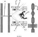
Fig. 1 is a side view in partial top down perspective of an exemplary embodiment of a water current shield; -
Fig. 2 is a top down view in partial perspective with a detail of an hinge assembly of an exemplary embodiment of a water current shield; -
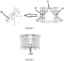
Fig. 3 is a view in partial frontal perspective of an exemplary embodiment of a water current shield system; -
Fig. 4 is a view in partial top down perspective of an exemplary embodiment of a water current shield system; -
Fig. 5 is a view in partial perspective of an exemplary embodiment of a water current shield system; and -
Fig. 6 is a view in partial top down perspective of an exemplary embodiment of a water current shield system. - Referring generally to
Figs. 5 and6 , in its various embodiments water current shield 1 may be used to improve safety fordiver 200 and/or remotely operated vehicle (ROV) 300 by shielding them from water currents, thereby allowing them to avoid excess fatigue from the water currents at the underwater work sites. It may also extend an environmental range that the projects can proceed in without facing the need to go on weather standby or off hire. As described below, in its embodiments, water current shield 1 provides a shield from ocean or other water currents that either diver 200 and/orROV 300 could get behind and work while being protected from the water current while working in a localized location such as hull piping flange connections. - Referring now generally to
Fig. 1 , water current shield 1 comprisesframe 10; a predetermined set oflouver assemblies 30 operatively connected toframe 10, each louver assembly comprising one or more selectablymovable louvers 31,32 (Fig. 2 ); and louver mover 50 operatively connected to each selectably movable louver. -
Frame 10 comprisespost 11; a set of upper louver attachment arms 12 connected topost 11 at a predetermined offset angle; a complimentary set of lowerlouver attachment arms 13 connected topost 11 at the same predetermined offset angle; andstationer 14 connected to the post. Upper louver attachment arms 12 and lowerlouver attachment arms 13 may be fixed at the predetermined offset angle or adjustable to dynamically set upper louver attachment arms 12 and lowerlouver attachment arms 13 at the predetermined offset angle. - As used herein,
stationer 14 comprises structures configured to provide stability to water current shield 1 once deployed in water such as on a subsea sea bed.Stationer 14 may comprise a predetermined set of feet, suction pads, eductors, or the like, or a combination thereof. Typically, if present a first subset of the predetermined set of suction pads or eductors is configured to operate independently of a second subset of the predetermined set of suction pads or eductors such as by use of check valves and/or associated plumbing (not shown in the figures). - Louvers 31, 32 may be selectively and independently opened or closed, providing protection from the water current for the diver's work area. Generally, the predetermined set of
louver assemblies 30 are hingedly connected toframe 10 such as by hinge assemblies 33 (Fig. 2 ) and/orpivots 33 associated with the set of upper louver attachment arms 12,hinges 33 associated with the set of lowerlouver attachment arms 13, or the like, or a combination thereof. Typically, a space is created within or substantially within the predetermined set oflouver assemblies 30 which defines a space sufficient to protect a diver and/or a remotely operated vehicle from water currents. - Louver mover 50 is operatively connected to the predetermined set of
louver assemblies 30. In embodiments, louver mover 50 comprises one ormover closure bars first closure bar 51 may be attached tolouver assembly 31 andsecond closure bar 52 may be attached tolouver assembly 32. Theseclosure bars closure bars handles Fig. 5 ) and/or ROV 300 (Fig. 6 ) and may be manipulated and/or secured in a louver open, partially open, and/or closed position by use ofpins - Referring additionally to
Fig. 4 , in certainembodiments safety strap 60, adapted to provide redundant protection for diver 200 (Fig. 5 ) should any of the suction pads or eductors loose vacuum, may be used to secure water current shield 1 in place such as by being attached to a predetermined part offrame 10 such as to offsettingpadeyes 15 which may be located at various predetermined portions offrame 10, e.g. on set of upper louver attachment arms 12 and/orpost 11. - Referring now to
Figs. 4-6 , system 100 comprises water current shield 1, as described above; crane 110 (not shown in the figures) adapted to attach to and lower water current shield 1 into water such as by cables 121 attached tooffsetting padeyes 11; hold-back rigging 120 deployable from a far side of the facility (up current side); andROV 300. ROV 300 typically comprises hydraulichot stab 310 adapted to power one or more hydraulic suction pumps 142 (Fig. 3 ) which will pull a vacuum instationer 14. - In the operation of an exemplary embodiment, water current shield 1 may be lowered with crane 110 and pulled into position such as with hold-back rigging 120 from the far side of the facility (up current side). The current shield is as described above and comprises
louver assemblies 30 that may be opened to reduce the drag from the current, making it possible to position and set water current shield 1 during the installation to allow the water current to flow around and/or through water current shield 1 during installation. This helps to avoid over loading the rigging used to install water current shield 1 and ease the positioning of water current shield 1 where needed. -
Stationer 14, as described above, may be used to hold water current shield 1 in place without damaging the underwater work site. - An area directly up current of the underwater work site may be cleaned of any heavy marine growth to the extent allowed by the water currents. Hold-back rigging 120 may be used to pull water current shield 1 into position as directed by
ROV 300 and carefully positioned just up current of the proposed underwater work site. - Once lowered into place, such as in contact with
underwater pontoon 400,ROV 300 may use hydraulic hot stab 141 to power hydraulic suction pumps 142 (Fig. 3 ) to pull a vacuum instationer 14.Stationer 14 may comprise multiple suction pads or eductors to selectively allow for some of the pads or eductors to not be able to pull a vacuum due to marine growth, large dents, hull deformities, and the like, or a combination thereof. Where multiple suction pads and/or eductors are present, predetermined sets of these may be independently operable. By pulling the vacuum instationer 14 such as with one or more hydraulic pumps 141 driven byROV 300, use of surface umbilicals which would create serious drag on water current shield 1 due to the vertical loading on a umbilical from the current flow may be avoided. Oncestationer 14 is confirmed to be holding a proper suction such as via gage reading,louvers 31 may be fully or partially closed, blocking the water current at the proposed underwater work site. - Making water current shield 1 installable by ROV 300 allows water current shield 1 to be installed in water currents in which
ROV 300 can operate but diver 200 could not. The movable louver system further allows water current shielding when needed, butlouvers - The foregoing disclosure and description of the inventions are illustrative and explanatory. Various changes in the size, shape, and materials, as well as in the details of the illustrative construction and/or an illustrative method may be made without departing from the invention.
Claims (15)
- A water current shield (1) for providing an object with protection from a water current at a subsea work site, the water current shield comprising:a. a frame (10), comprising:i. a post (11);ii. a set of upper louver attachment arms (12), a first member of the set of upper louver attachment arms (12) connected to the post (11) at a first predetermined offset angle and a second member of the set of upper louver attachment arms (12) connected to the post (11) at a second predetermined offset angle;iii. a set of lower louver attachment arms (13), a first member of the set of lower louver attachment arms (13) connected to the post (11) at the first predetermined offset angle and a second member of the set of lower louver attachment arms (13) connected to the post (11) at the second predetermined offset angle; andiv. a stationer (14) connected to the post (11);b. a predetermined set of louver assemblies (30) operatively connected to the frame (10) intermediate the upper louver attachment arms (12) and the lower louver attachment arms (13), each louver assembly (30) comprising a selectably movable louver (31,32); andc. a louver mover (50) operatively connected to each selectably movable louver (31,32) and operative to allow the louver assemblies (30) to be placed and secured selectively into an open, partially open, and/or closed position.
- The water current shield of Claim 1, wherein the set of louver assemblies (30) are hingedly connected to the frame (10).
- The water current shield of Claim 1, wherein the stationer (14) comprises a predetermined set of suction pads and/or eductors, a first subset of the predetermined set of suction pads and/or eductors configured to operate independently of a second subset of the predetermined set of suction pads and/or eductors by use of check valves and assorted plumbing.
- The water current shield of Claim 1, further comprising a safety strap (60) connected to a securing point on the frame (10), the safety strap adapted to be connected to a structure subsea.
- The water current shield of Claim 1, wherein the predetermined set of louver assemblies (30) are connected to the post (11) in a manner that defines a space sufficient to protect a diver (200), or a remotely operated vehicle (300), from water currents.
- The water current shield of Claim 1, wherein the louver mover (50) comprises a mover closure bar (51) operatively connected to a louver assembly (30).
- The water current shield of Claim 6, wherein:a. the mover closure bar (51) comprises a first closure bar (51) operatively connected to a first louver assembly (30); andb. a second closure bar (52) operatively connected to a second louver assembly (30).
- The water current shield of Claim 6, further comprising a handle (53, 54) operatively connected to the mover closure bar (51).
- The water current shield of Claim 6, further comprising a pin (55, 56) configured to secure the louver assembly (30) into an open, partially open, and/or closed position.
- A system, comprising:a. a water current shield (1), as claimed in claim 1;b. a crane (110) adapted to attach and lower the water current shield into water;c. hold-back rigging (120) attached to the water current shield from an up-current side; andd. a remotely operated vehicle (300) comprising a hydraulic hot stab (310) adapted to power hydraulic suction pumps (142) which will pull a vacuum in the stationer (14).
- A method of providing an object with protection from a water current at a subsea work site using a water current shield (1) comprising a frame (10), the frame comprising a post (11), a set of upper louver attachment arms (12) where a first member of the set of upper louver attachment arms (12) is connected to the post (11) at a first predetermined offset angle and a second member of the set of upper louver attachment arms (12) is connected to the post (11) at a second predetermined offset angle, a set of lower louver attachment arms (13) where a first member of the set of lower louver attachment arms (13) is connected to the post (11) at the first predetermined offset angle and a second member of the set of lower louver attachment arms (13) is connected to the post (11) at the second predetermined offset angle and a stationer (14) connected to the post (11), a predetermined set of louver assemblies (30) operatively connected to the frame (10) intermediate the upper louver attachment arms (12) and the lower louver attachment arms (13) where each louver assembly (30) comprises a selectably movable louver (31,32) and a louver mover (50) operatively connected to each selectably movable louver (31,32) and operative to allow the louver assemblies (30) to be placed and secured selectively into an open, partially open, and/or closed position, the method comprising:a. lowering the water current shield with a crane (110), the louvers (31,32) initially in a first position to allow water current to flow through the louvers;b. positioning the water current shield with hold-back rigging (120) from an up-current side of the subsea work site;c. adjusting an open or closed characteristic of the louvers (31,32) if drag from the water current needs to be reduced around the subsea work site; andd. closing the louvers (31,32) to protect an object (200,300) proximate the water current shield from the water current.
- The method of Claim 11, further comprising using a hydraulic hot stab (310) from a remotely operated vehicle (300) to power hydraulic suction pumps (142) and pull a vacuum in the stationer (14).
- The method of Claim 11, further comprising:a. using a gauge to confirm proper suction being maintained on the stationer (14); andb. once confirmed, closing the louvers (31,32) and blocking the water current at the subsea work site.
- The method of Claim 11, further comprising using the hold-back rigging (120) to pull the water current shield (1) into position as directed by a remotely operated vehicle (300) positioned just up current of the subsea work site.
- The method of Claim 11, wherein the object comprises a human diver (200) or a remotely operated vehicle (ROV) (300).
Applications Claiming Priority (2)
| Application Number | Priority Date | Filing Date | Title |
|---|---|---|---|
| US201562252454P | 2015-11-07 | 2015-11-07 | |
| PCT/US2016/060827 WO2017079742A1 (en) | 2015-11-07 | 2016-11-07 | Current shield |
Publications (3)
| Publication Number | Publication Date |
|---|---|
| EP3371376A1 EP3371376A1 (en) | 2018-09-12 |
| EP3371376A4 EP3371376A4 (en) | 2019-05-29 |
| EP3371376B1 true EP3371376B1 (en) | 2021-07-14 |
Family
ID=58663109
Family Applications (1)
| Application Number | Title | Priority Date | Filing Date |
|---|---|---|---|
| EP16863165.3A Active EP3371376B1 (en) | 2015-11-07 | 2016-11-07 | Current shield |
Country Status (3)
| Country | Link |
|---|---|
| US (1) | US10267002B2 (en) |
| EP (1) | EP3371376B1 (en) |
| WO (1) | WO2017079742A1 (en) |
Families Citing this family (2)
| Publication number | Priority date | Publication date | Assignee | Title |
|---|---|---|---|---|
| CN107352001B (en) * | 2017-07-30 | 2019-03-15 | 乐清市钜派企业管理咨询有限公司 | A portable underwater robot capable of changing the support area |
| FR3075161B1 (en) * | 2017-12-15 | 2020-01-03 | Prolarge | WATER CURRENT DEFLECTOR SYSTEM |
Family Cites Families (17)
| Publication number | Priority date | Publication date | Assignee | Title |
|---|---|---|---|---|
| US402055A (en) * | 1889-04-23 | Water-motor | ||
| US1449426A (en) * | 1921-10-19 | 1923-03-27 | Loveless John Mcm | Water motor |
| US2710505A (en) * | 1951-08-21 | 1955-06-14 | John W Magill | Baffle plate type breakwater unit for effecting wave energy dissipation |
| US3011316A (en) * | 1958-12-18 | 1961-12-05 | Allen B Wilson | Breakwater and method of dissipating waves |
| US4494008A (en) * | 1983-03-03 | 1985-01-15 | Patton Bennie N | Wind-driven generator |
| US4997310A (en) * | 1990-01-16 | 1991-03-05 | Rasmussen Frederick T | Portable floating wave dissipating device |
| US5069580A (en) * | 1990-09-25 | 1991-12-03 | Fssl, Inc. | Subsea payload installation system |
| NL1009246C2 (en) * | 1998-05-22 | 1999-11-24 | Hendrik De Bloeme | Method and device for performing work on an underwater object. |
| NZ520450A (en) * | 2002-07-30 | 2004-12-24 | Mooring Systems Ltd | Method of controlling a mooring system |
| US6954006B2 (en) * | 2003-11-10 | 2005-10-11 | Williams Jr Fred E | Hydroelectric system |
| WO2006126884A1 (en) * | 2005-03-29 | 2006-11-30 | Norse Cutting & Abandonment As | A method and a device for attaching a subsea cutting apparatus |
| US8664784B2 (en) * | 2005-09-12 | 2014-03-04 | Gulfstream Technologies, Inc. | Louvered turbine for generating electric power from a water current |
| US7673853B2 (en) * | 2006-10-12 | 2010-03-09 | Cordell Eldred Ebeling | Fencing section with adjustable fencing members |
| US20130005238A1 (en) * | 2011-06-29 | 2013-01-03 | Brandt Donald M | Air conditioner cover with opening and closing feature |
| WO2013049194A1 (en) * | 2011-09-26 | 2013-04-04 | Horton Wison Deepwater, Inc. | Modular relocatable offshore support tower |
| EP2855776A4 (en) * | 2012-06-05 | 2016-02-24 | Deron Nettles | System and method for shoreline preservation |
| US9303619B2 (en) * | 2012-11-16 | 2016-04-05 | Hydro Alternative Energy, Inc. | Hydrokinetic energy conversion system with buoyancy and ballast controls to harness underwater currents for the generation of electrical power |
-
2016
- 2016-11-07 WO PCT/US2016/060827 patent/WO2017079742A1/en not_active Ceased
- 2016-11-07 EP EP16863165.3A patent/EP3371376B1/en active Active
- 2016-11-07 US US15/344,951 patent/US10267002B2/en active Active - Reinstated
Also Published As
| Publication number | Publication date |
|---|---|
| EP3371376A4 (en) | 2019-05-29 |
| US10267002B2 (en) | 2019-04-23 |
| EP3371376A1 (en) | 2018-09-12 |
| US20170130413A1 (en) | 2017-05-11 |
| WO2017079742A1 (en) | 2017-05-11 |
Similar Documents
| Publication | Publication Date | Title |
|---|---|---|
| US20090162144A1 (en) | Tidal Flow Power Generation | |
| MX2008009139A (en) | Mooring system. | |
| KR20130124207A (en) | A docking device for facilitating a transfer between a vessel and an offshore structure | |
| JP2020083315A (en) | Subsurface marine battery pack | |
| US6851895B2 (en) | Methods of and apparatus for mooring and for connecting lines to articles on the seabed | |
| CN106400737B (en) | For storing and unloading the facility of oil gas | |
| US10267002B2 (en) | Current shield | |
| EP2694801B1 (en) | Submersible apparatus and methods of installing anchoring equipment | |
| AU2017313123B2 (en) | Biased fairlead clump weight | |
| US3630033A (en) | Apparatus for controlling oil slicks | |
| KR101415488B1 (en) | Anchoring installation of the floated generating apparatus among the sea | |
| CN103569311B (en) | Propelling unit mounting and positioning device and propelling unit installation method under water | |
| AU2021290342A1 (en) | Marine power generation system | |
| WO2010132433A2 (en) | Drilling rig ice protector apparatus and methods | |
| JP2006158160A (en) | Long body for floating sea and its installation method | |
| KR102027904B1 (en) | Ship equipped moon pool protecter | |
| GB2514773A (en) | Underwater turbine installation apparatus and methods | |
| WO2015110364A1 (en) | Submersible lift frame | |
| JPH0860645A (en) | Underwater structure construction method | |
| EP2844541B1 (en) | Ship with vertical draught system | |
| KR20130003914A (en) | Method for mounting azimuth thruster for ship on land | |
| KR101588719B1 (en) | Ship | |
| JP3210969U (en) | Tidal current generator | |
| CN103946455B (en) | Facility and method for storing and offloading oil and gas | |
| CN121149903A (en) | Installation System and Method for Submarine Cable Anchor Damage Protection Device Based on Unmanned Vessel |
Legal Events
| Date | Code | Title | Description |
|---|---|---|---|
| STAA | Information on the status of an ep patent application or granted ep patent |
Free format text: STATUS: THE INTERNATIONAL PUBLICATION HAS BEEN MADE |
|
| PUAI | Public reference made under article 153(3) epc to a published international application that has entered the european phase |
Free format text: ORIGINAL CODE: 0009012 |
|
| STAA | Information on the status of an ep patent application or granted ep patent |
Free format text: STATUS: REQUEST FOR EXAMINATION WAS MADE |
|
| 17P | Request for examination filed |
Effective date: 20180515 |
|
| AK | Designated contracting states |
Kind code of ref document: A1 Designated state(s): AL AT BE BG CH CY CZ DE DK EE ES FI FR GB GR HR HU IE IS IT LI LT LU LV MC MK MT NL NO PL PT RO RS SE SI SK SM TR |
|
| AX | Request for extension of the european patent |
Extension state: BA ME |
|
| DAV | Request for validation of the european patent (deleted) | ||
| DAX | Request for extension of the european patent (deleted) | ||
| A4 | Supplementary search report drawn up and despatched |
Effective date: 20190430 |
|
| RIC1 | Information provided on ipc code assigned before grant |
Ipc: E02B 5/08 20060101ALI20190424BHEP Ipc: E06B 9/04 20060101ALI20190424BHEP Ipc: E04H 17/18 20060101ALI20190424BHEP Ipc: E02B 3/04 20060101AFI20190424BHEP Ipc: E06B 9/26 20060101ALI20190424BHEP Ipc: B63C 11/52 20060101ALI20190424BHEP Ipc: E06B 7/09 20060101ALI20190424BHEP Ipc: E06B 9/01 20060101ALI20190424BHEP Ipc: E06B 7/086 20060101ALI20190424BHEP Ipc: F24F 13/15 20060101ALI20190424BHEP |
|
| GRAP | Despatch of communication of intention to grant a patent |
Free format text: ORIGINAL CODE: EPIDOSNIGR1 |
|
| STAA | Information on the status of an ep patent application or granted ep patent |
Free format text: STATUS: GRANT OF PATENT IS INTENDED |
|
| INTG | Intention to grant announced |
Effective date: 20210309 |
|
| GRAS | Grant fee paid |
Free format text: ORIGINAL CODE: EPIDOSNIGR3 |
|
| GRAA | (expected) grant |
Free format text: ORIGINAL CODE: 0009210 |
|
| STAA | Information on the status of an ep patent application or granted ep patent |
Free format text: STATUS: THE PATENT HAS BEEN GRANTED |
|
| AK | Designated contracting states |
Kind code of ref document: B1 Designated state(s): AL AT BE BG CH CY CZ DE DK EE ES FI FR GB GR HR HU IE IS IT LI LT LU LV MC MK MT NL NO PL PT RO RS SE SI SK SM TR |
|
| REG | Reference to a national code |
Ref country code: GB Ref legal event code: FG4D |
|
| RIN1 | Information on inventor provided before grant (corrected) |
Inventor name: COUCH, JACK Inventor name: CASTON, MATTHEW JAMES Inventor name: GEBHARDT, KYLE WILLIAM Inventor name: HERMANN, SCOTT EDWARD |
|
| REG | Reference to a national code |
Ref country code: DE Ref legal event code: R096 Ref document number: 602016060746 Country of ref document: DE |
|
| REG | Reference to a national code |
Ref country code: IE Ref legal event code: FG4D |
|
| REG | Reference to a national code |
Ref country code: AT Ref legal event code: REF Ref document number: 1410762 Country of ref document: AT Kind code of ref document: T Effective date: 20210815 |
|
| REG | Reference to a national code |
Ref country code: LT Ref legal event code: MG9D |
|
| REG | Reference to a national code |
Ref country code: NO Ref legal event code: T2 Effective date: 20210714 |
|
| REG | Reference to a national code |
Ref country code: NL Ref legal event code: MP Effective date: 20210714 |
|
| REG | Reference to a national code |
Ref country code: AT Ref legal event code: MK05 Ref document number: 1410762 Country of ref document: AT Kind code of ref document: T Effective date: 20210714 |
|
| PG25 | Lapsed in a contracting state [announced via postgrant information from national office to epo] |
Ref country code: HR Free format text: LAPSE BECAUSE OF FAILURE TO SUBMIT A TRANSLATION OF THE DESCRIPTION OR TO PAY THE FEE WITHIN THE PRESCRIBED TIME-LIMIT Effective date: 20210714 Ref country code: ES Free format text: LAPSE BECAUSE OF FAILURE TO SUBMIT A TRANSLATION OF THE DESCRIPTION OR TO PAY THE FEE WITHIN THE PRESCRIBED TIME-LIMIT Effective date: 20210714 Ref country code: FI Free format text: LAPSE BECAUSE OF FAILURE TO SUBMIT A TRANSLATION OF THE DESCRIPTION OR TO PAY THE FEE WITHIN THE PRESCRIBED TIME-LIMIT Effective date: 20210714 Ref country code: PT Free format text: LAPSE BECAUSE OF FAILURE TO SUBMIT A TRANSLATION OF THE DESCRIPTION OR TO PAY THE FEE WITHIN THE PRESCRIBED TIME-LIMIT Effective date: 20211115 Ref country code: NL Free format text: LAPSE BECAUSE OF FAILURE TO SUBMIT A TRANSLATION OF THE DESCRIPTION OR TO PAY THE FEE WITHIN THE PRESCRIBED TIME-LIMIT Effective date: 20210714 Ref country code: LT Free format text: LAPSE BECAUSE OF FAILURE TO SUBMIT A TRANSLATION OF THE DESCRIPTION OR TO PAY THE FEE WITHIN THE PRESCRIBED TIME-LIMIT Effective date: 20210714 Ref country code: BG Free format text: LAPSE BECAUSE OF FAILURE TO SUBMIT A TRANSLATION OF THE DESCRIPTION OR TO PAY THE FEE WITHIN THE PRESCRIBED TIME-LIMIT Effective date: 20211014 Ref country code: AT Free format text: LAPSE BECAUSE OF FAILURE TO SUBMIT A TRANSLATION OF THE DESCRIPTION OR TO PAY THE FEE WITHIN THE PRESCRIBED TIME-LIMIT Effective date: 20210714 Ref country code: SE Free format text: LAPSE BECAUSE OF FAILURE TO SUBMIT A TRANSLATION OF THE DESCRIPTION OR TO PAY THE FEE WITHIN THE PRESCRIBED TIME-LIMIT Effective date: 20210714 Ref country code: RS Free format text: LAPSE BECAUSE OF FAILURE TO SUBMIT A TRANSLATION OF THE DESCRIPTION OR TO PAY THE FEE WITHIN THE PRESCRIBED TIME-LIMIT Effective date: 20210714 |
|
| PG25 | Lapsed in a contracting state [announced via postgrant information from national office to epo] |
Ref country code: PL Free format text: LAPSE BECAUSE OF FAILURE TO SUBMIT A TRANSLATION OF THE DESCRIPTION OR TO PAY THE FEE WITHIN THE PRESCRIBED TIME-LIMIT Effective date: 20210714 Ref country code: LV Free format text: LAPSE BECAUSE OF FAILURE TO SUBMIT A TRANSLATION OF THE DESCRIPTION OR TO PAY THE FEE WITHIN THE PRESCRIBED TIME-LIMIT Effective date: 20210714 Ref country code: GR Free format text: LAPSE BECAUSE OF FAILURE TO SUBMIT A TRANSLATION OF THE DESCRIPTION OR TO PAY THE FEE WITHIN THE PRESCRIBED TIME-LIMIT Effective date: 20211015 |
|
| REG | Reference to a national code |
Ref country code: DE Ref legal event code: R097 Ref document number: 602016060746 Country of ref document: DE |
|
| PG25 | Lapsed in a contracting state [announced via postgrant information from national office to epo] |
Ref country code: DK Free format text: LAPSE BECAUSE OF FAILURE TO SUBMIT A TRANSLATION OF THE DESCRIPTION OR TO PAY THE FEE WITHIN THE PRESCRIBED TIME-LIMIT Effective date: 20210714 |
|
| PLBE | No opposition filed within time limit |
Free format text: ORIGINAL CODE: 0009261 |
|
| STAA | Information on the status of an ep patent application or granted ep patent |
Free format text: STATUS: NO OPPOSITION FILED WITHIN TIME LIMIT |
|
| PG25 | Lapsed in a contracting state [announced via postgrant information from national office to epo] |
Ref country code: SM Free format text: LAPSE BECAUSE OF FAILURE TO SUBMIT A TRANSLATION OF THE DESCRIPTION OR TO PAY THE FEE WITHIN THE PRESCRIBED TIME-LIMIT Effective date: 20210714 Ref country code: SK Free format text: LAPSE BECAUSE OF FAILURE TO SUBMIT A TRANSLATION OF THE DESCRIPTION OR TO PAY THE FEE WITHIN THE PRESCRIBED TIME-LIMIT Effective date: 20210714 Ref country code: RO Free format text: LAPSE BECAUSE OF FAILURE TO SUBMIT A TRANSLATION OF THE DESCRIPTION OR TO PAY THE FEE WITHIN THE PRESCRIBED TIME-LIMIT Effective date: 20210714 Ref country code: EE Free format text: LAPSE BECAUSE OF FAILURE TO SUBMIT A TRANSLATION OF THE DESCRIPTION OR TO PAY THE FEE WITHIN THE PRESCRIBED TIME-LIMIT Effective date: 20210714 Ref country code: CZ Free format text: LAPSE BECAUSE OF FAILURE TO SUBMIT A TRANSLATION OF THE DESCRIPTION OR TO PAY THE FEE WITHIN THE PRESCRIBED TIME-LIMIT Effective date: 20210714 Ref country code: AL Free format text: LAPSE BECAUSE OF FAILURE TO SUBMIT A TRANSLATION OF THE DESCRIPTION OR TO PAY THE FEE WITHIN THE PRESCRIBED TIME-LIMIT Effective date: 20210714 |
|
| REG | Reference to a national code |
Ref country code: DE Ref legal event code: R119 Ref document number: 602016060746 Country of ref document: DE |
|
| 26N | No opposition filed |
Effective date: 20220419 |
|
| PG25 | Lapsed in a contracting state [announced via postgrant information from national office to epo] |
Ref country code: MC Free format text: LAPSE BECAUSE OF FAILURE TO SUBMIT A TRANSLATION OF THE DESCRIPTION OR TO PAY THE FEE WITHIN THE PRESCRIBED TIME-LIMIT Effective date: 20210714 |
|
| REG | Reference to a national code |
Ref country code: CH Ref legal event code: PL |
|
| PG25 | Lapsed in a contracting state [announced via postgrant information from national office to epo] |
Ref country code: LU Free format text: LAPSE BECAUSE OF NON-PAYMENT OF DUE FEES Effective date: 20211107 Ref country code: IT Free format text: LAPSE BECAUSE OF FAILURE TO SUBMIT A TRANSLATION OF THE DESCRIPTION OR TO PAY THE FEE WITHIN THE PRESCRIBED TIME-LIMIT Effective date: 20210714 Ref country code: BE Free format text: LAPSE BECAUSE OF NON-PAYMENT OF DUE FEES Effective date: 20211130 |
|
| REG | Reference to a national code |
Ref country code: BE Ref legal event code: MM Effective date: 20211130 |
|
| PG25 | Lapsed in a contracting state [announced via postgrant information from national office to epo] |
Ref country code: LI Free format text: LAPSE BECAUSE OF NON-PAYMENT OF DUE FEES Effective date: 20211130 Ref country code: CH Free format text: LAPSE BECAUSE OF NON-PAYMENT OF DUE FEES Effective date: 20211130 |
|
| PG25 | Lapsed in a contracting state [announced via postgrant information from national office to epo] |
Ref country code: IE Free format text: LAPSE BECAUSE OF NON-PAYMENT OF DUE FEES Effective date: 20211107 Ref country code: DE Free format text: LAPSE BECAUSE OF NON-PAYMENT OF DUE FEES Effective date: 20220601 |
|
| PG25 | Lapsed in a contracting state [announced via postgrant information from national office to epo] |
Ref country code: FR Free format text: LAPSE BECAUSE OF NON-PAYMENT OF DUE FEES Effective date: 20211130 |
|
| PG25 | Lapsed in a contracting state [announced via postgrant information from national office to epo] |
Ref country code: HU Free format text: LAPSE BECAUSE OF FAILURE TO SUBMIT A TRANSLATION OF THE DESCRIPTION OR TO PAY THE FEE WITHIN THE PRESCRIBED TIME-LIMIT; INVALID AB INITIO Effective date: 20161107 |
|
| PG25 | Lapsed in a contracting state [announced via postgrant information from national office to epo] |
Ref country code: CY Free format text: LAPSE BECAUSE OF FAILURE TO SUBMIT A TRANSLATION OF THE DESCRIPTION OR TO PAY THE FEE WITHIN THE PRESCRIBED TIME-LIMIT Effective date: 20210714 |
|
| P01 | Opt-out of the competence of the unified patent court (upc) registered |
Effective date: 20230526 |
|
| PG25 | Lapsed in a contracting state [announced via postgrant information from national office to epo] |
Ref country code: MK Free format text: LAPSE BECAUSE OF FAILURE TO SUBMIT A TRANSLATION OF THE DESCRIPTION OR TO PAY THE FEE WITHIN THE PRESCRIBED TIME-LIMIT Effective date: 20210714 |
|
| PG25 | Lapsed in a contracting state [announced via postgrant information from national office to epo] |
Ref country code: MT Free format text: LAPSE BECAUSE OF FAILURE TO SUBMIT A TRANSLATION OF THE DESCRIPTION OR TO PAY THE FEE WITHIN THE PRESCRIBED TIME-LIMIT Effective date: 20210714 |
|
| PG25 | Lapsed in a contracting state [announced via postgrant information from national office to epo] |
Ref country code: TR Free format text: LAPSE BECAUSE OF FAILURE TO SUBMIT A TRANSLATION OF THE DESCRIPTION OR TO PAY THE FEE WITHIN THE PRESCRIBED TIME-LIMIT Effective date: 20210714 |
|
| PGFP | Annual fee paid to national office [announced via postgrant information from national office to epo] |
Ref country code: NO Payment date: 20251229 Year of fee payment: 10 |
|
| PGFP | Annual fee paid to national office [announced via postgrant information from national office to epo] |
Ref country code: GB Payment date: 20260106 Year of fee payment: 10 |