EP3371069B1 - Guiding rail provided with intermediate material and container provided with such guiding rail - Google Patents
Guiding rail provided with intermediate material and container provided with such guiding rail Download PDFInfo
- Publication number
- EP3371069B1 EP3371069B1 EP16709360.8A EP16709360A EP3371069B1 EP 3371069 B1 EP3371069 B1 EP 3371069B1 EP 16709360 A EP16709360 A EP 16709360A EP 3371069 B1 EP3371069 B1 EP 3371069B1
- Authority
- EP
- European Patent Office
- Prior art keywords
- dunnage
- guiding rail
- insert
- container
- recess
- Prior art date
- Legal status (The legal status is an assumption and is not a legal conclusion. Google has not performed a legal analysis and makes no representation as to the accuracy of the status listed.)
- Active
Links
Images


Classifications
-
- B—PERFORMING OPERATIONS; TRANSPORTING
- B65—CONVEYING; PACKING; STORING; HANDLING THIN OR FILAMENTARY MATERIAL
- B65D—CONTAINERS FOR STORAGE OR TRANSPORT OF ARTICLES OR MATERIALS, e.g. BAGS, BARRELS, BOTTLES, BOXES, CANS, CARTONS, CRATES, DRUMS, JARS, TANKS, HOPPERS, FORWARDING CONTAINERS; ACCESSORIES, CLOSURES, OR FITTINGS THEREFOR; PACKAGING ELEMENTS; PACKAGES
- B65D19/00—Pallets or like platforms, with or without side walls, for supporting loads to be lifted or lowered
- B65D19/02—Rigid pallets with side walls, e.g. box pallets
- B65D19/06—Rigid pallets with side walls, e.g. box pallets with bodies formed by uniting or interconnecting two or more components
-
- B—PERFORMING OPERATIONS; TRANSPORTING
- B65—CONVEYING; PACKING; STORING; HANDLING THIN OR FILAMENTARY MATERIAL
- B65D—CONTAINERS FOR STORAGE OR TRANSPORT OF ARTICLES OR MATERIALS, e.g. BAGS, BARRELS, BOTTLES, BOXES, CANS, CARTONS, CRATES, DRUMS, JARS, TANKS, HOPPERS, FORWARDING CONTAINERS; ACCESSORIES, CLOSURES, OR FITTINGS THEREFOR; PACKAGING ELEMENTS; PACKAGES
- B65D19/00—Pallets or like platforms, with or without side walls, for supporting loads to be lifted or lowered
- B65D19/38—Details or accessories
- B65D19/385—Frames, corner posts or pallet converters, e.g. for facilitating stacking of charged pallets
-
- B—PERFORMING OPERATIONS; TRANSPORTING
- B65—CONVEYING; PACKING; STORING; HANDLING THIN OR FILAMENTARY MATERIAL
- B65D—CONTAINERS FOR STORAGE OR TRANSPORT OF ARTICLES OR MATERIALS, e.g. BAGS, BARRELS, BOTTLES, BOXES, CANS, CARTONS, CRATES, DRUMS, JARS, TANKS, HOPPERS, FORWARDING CONTAINERS; ACCESSORIES, CLOSURES, OR FITTINGS THEREFOR; PACKAGING ELEMENTS; PACKAGES
- B65D81/00—Containers, packaging elements, or packages, for contents presenting particular transport or storage problems, or adapted to be used for non-packaging purposes after removal of contents
- B65D81/02—Containers, packaging elements, or packages, for contents presenting particular transport or storage problems, or adapted to be used for non-packaging purposes after removal of contents specially adapted to protect contents from mechanical damage
- B65D81/05—Containers, packaging elements, or packages, for contents presenting particular transport or storage problems, or adapted to be used for non-packaging purposes after removal of contents specially adapted to protect contents from mechanical damage maintaining contents at spaced relation from package walls, or from other contents
-
- B—PERFORMING OPERATIONS; TRANSPORTING
- B65—CONVEYING; PACKING; STORING; HANDLING THIN OR FILAMENTARY MATERIAL
- B65D—CONTAINERS FOR STORAGE OR TRANSPORT OF ARTICLES OR MATERIALS, e.g. BAGS, BARRELS, BOTTLES, BOXES, CANS, CARTONS, CRATES, DRUMS, JARS, TANKS, HOPPERS, FORWARDING CONTAINERS; ACCESSORIES, CLOSURES, OR FITTINGS THEREFOR; PACKAGING ELEMENTS; PACKAGES
- B65D2519/00—Pallets or like platforms, with or without side walls, for supporting loads to be lifted or lowered
- B65D2519/00004—Details relating to pallets
- B65D2519/00258—Overall construction
- B65D2519/00313—Overall construction of the base surface
- B65D2519/00328—Overall construction of the base surface shape of the contact surface of the base
- B65D2519/00338—Overall construction of the base surface shape of the contact surface of the base contact surface having a discrete foot-like shape
-
- B—PERFORMING OPERATIONS; TRANSPORTING
- B65—CONVEYING; PACKING; STORING; HANDLING THIN OR FILAMENTARY MATERIAL
- B65D—CONTAINERS FOR STORAGE OR TRANSPORT OF ARTICLES OR MATERIALS, e.g. BAGS, BARRELS, BOTTLES, BOXES, CANS, CARTONS, CRATES, DRUMS, JARS, TANKS, HOPPERS, FORWARDING CONTAINERS; ACCESSORIES, CLOSURES, OR FITTINGS THEREFOR; PACKAGING ELEMENTS; PACKAGES
- B65D2519/00—Pallets or like platforms, with or without side walls, for supporting loads to be lifted or lowered
- B65D2519/00004—Details relating to pallets
- B65D2519/00258—Overall construction
- B65D2519/00492—Overall construction of the side walls
- B65D2519/00497—Overall construction of the side walls whereby at least one side wall is made of one piece
-
- B—PERFORMING OPERATIONS; TRANSPORTING
- B65—CONVEYING; PACKING; STORING; HANDLING THIN OR FILAMENTARY MATERIAL
- B65D—CONTAINERS FOR STORAGE OR TRANSPORT OF ARTICLES OR MATERIALS, e.g. BAGS, BARRELS, BOTTLES, BOXES, CANS, CARTONS, CRATES, DRUMS, JARS, TANKS, HOPPERS, FORWARDING CONTAINERS; ACCESSORIES, CLOSURES, OR FITTINGS THEREFOR; PACKAGING ELEMENTS; PACKAGES
- B65D2519/00—Pallets or like platforms, with or without side walls, for supporting loads to be lifted or lowered
- B65D2519/00004—Details relating to pallets
- B65D2519/00547—Connections
- B65D2519/00577—Connections structures connecting side walls, including corner posts, to each other
- B65D2519/00582—Connections structures connecting side walls, including corner posts, to each other structures intended to be disassembled, i.e. collapsible or dismountable
-
- B—PERFORMING OPERATIONS; TRANSPORTING
- B65—CONVEYING; PACKING; STORING; HANDLING THIN OR FILAMENTARY MATERIAL
- B65D—CONTAINERS FOR STORAGE OR TRANSPORT OF ARTICLES OR MATERIALS, e.g. BAGS, BARRELS, BOTTLES, BOXES, CANS, CARTONS, CRATES, DRUMS, JARS, TANKS, HOPPERS, FORWARDING CONTAINERS; ACCESSORIES, CLOSURES, OR FITTINGS THEREFOR; PACKAGING ELEMENTS; PACKAGES
- B65D2519/00—Pallets or like platforms, with or without side walls, for supporting loads to be lifted or lowered
- B65D2519/00004—Details relating to pallets
- B65D2519/00547—Connections
- B65D2519/00636—Connections structures connecting side walls to the pallet
- B65D2519/00641—Structures intended to be disassembled
-
- B—PERFORMING OPERATIONS; TRANSPORTING
- B65—CONVEYING; PACKING; STORING; HANDLING THIN OR FILAMENTARY MATERIAL
- B65D—CONTAINERS FOR STORAGE OR TRANSPORT OF ARTICLES OR MATERIALS, e.g. BAGS, BARRELS, BOTTLES, BOXES, CANS, CARTONS, CRATES, DRUMS, JARS, TANKS, HOPPERS, FORWARDING CONTAINERS; ACCESSORIES, CLOSURES, OR FITTINGS THEREFOR; PACKAGING ELEMENTS; PACKAGES
- B65D2519/00—Pallets or like platforms, with or without side walls, for supporting loads to be lifted or lowered
- B65D2519/00004—Details relating to pallets
- B65D2519/00736—Details
- B65D2519/00776—Accessories for manipulating the pallet
- B65D2519/00786—Accessories for manipulating the pallet for lifting, e.g. hooks, loops
- B65D2519/00791—Accessories for manipulating the pallet for lifting, e.g. hooks, loops handles, handgrip holes
-
- B—PERFORMING OPERATIONS; TRANSPORTING
- B65—CONVEYING; PACKING; STORING; HANDLING THIN OR FILAMENTARY MATERIAL
- B65D—CONTAINERS FOR STORAGE OR TRANSPORT OF ARTICLES OR MATERIALS, e.g. BAGS, BARRELS, BOTTLES, BOXES, CANS, CARTONS, CRATES, DRUMS, JARS, TANKS, HOPPERS, FORWARDING CONTAINERS; ACCESSORIES, CLOSURES, OR FITTINGS THEREFOR; PACKAGING ELEMENTS; PACKAGES
- B65D2519/00—Pallets or like platforms, with or without side walls, for supporting loads to be lifted or lowered
- B65D2519/00004—Details relating to pallets
- B65D2519/00736—Details
- B65D2519/0081—Elements or devices for locating articles
- B65D2519/0082—Elements or devices for locating articles in the side wall
-
- B—PERFORMING OPERATIONS; TRANSPORTING
- B65—CONVEYING; PACKING; STORING; HANDLING THIN OR FILAMENTARY MATERIAL
- B65D—CONTAINERS FOR STORAGE OR TRANSPORT OF ARTICLES OR MATERIALS, e.g. BAGS, BARRELS, BOTTLES, BOXES, CANS, CARTONS, CRATES, DRUMS, JARS, TANKS, HOPPERS, FORWARDING CONTAINERS; ACCESSORIES, CLOSURES, OR FITTINGS THEREFOR; PACKAGING ELEMENTS; PACKAGES
- B65D2519/00—Pallets or like platforms, with or without side walls, for supporting loads to be lifted or lowered
- B65D2519/00004—Details relating to pallets
- B65D2519/00736—Details
- B65D2519/00865—Collapsible, i.e. at least two constitutive elements remaining hingedly connected
- B65D2519/00875—Collapsible, i.e. at least two constitutive elements remaining hingedly connected collapsible side walls
Definitions
- the invention pertains to the technical field of systems for transportation and storage of goods provided with guiding rails and flexible dunnage.
- Handling units like boxes, racks or other, provided with guiding rails supporting flexible movable dunnage, are well known in the art. These handling units with dunnage, manufactured of materials like plastic, woven textile or non-woven textile, are used to transport a variety of goods all over the world. It is essential that the dunnage can be easily manipulated by the factory workers, who only have a limited time to fill or empty the dunnage.
- aluminum is the standard material to produce such guiding rails.
- aluminum has a high coefficient of kinetic friction, obliging the workers using both hands on the dunnage (one hand on the left side close to the guiding rail, one hand on the right side close to the guiding rail) to slide the dunnage along the rails in the handling units.
- This issue is in particular, but not only, the case when the flexible dunnage is self-supportive and not supported by a solid dunnage support.
- Transport devices with movable flexible dunnage can be divided in two categories.
- a first category of such transport devices comprises solid dunnage supports, like strut bars, which are mounted between the guiding rails by means of gliding elements. These transport devices need inventive systems to be collapsible when returned empty, which is a serious drawback for such transport devices. Moreover, when the dunnage support is skewed between the guiding rails, the dunnage can get blocked, due to the large friction between the gliding elements and the recess of the guiding rail.
- a second category comprises dunnage which is self-supportive, with gliding elements mounted directly on the dunnage or attached by means of a flexible connection like a textile band.
- US 2013/0175912 A1 discloses a guiding rail according to the preamble of claim 1 and a container according to the preamble of claim 9.
- the present invention aims to resolve at least some of the problems mentioned above.
- the invention thereto aims to provide an improved guiding rail, both inexpensive, enabling easy and effortless manipulation of the dunnage with or without dunnage supports and easy to install.
- the object of the current invention allows a one-hand operation when moving the dunnage in the box, which enhances greatly the efficiency of the operators of such devices.
- the present invention provides an improved guiding rail which can be used in storing and transporting devices provided with dunnage, which can be easily and effortlessly moved along the guiding rails, preferably by a one-hand operation.
- the present invention discloses a guiding rail according to claim 1.
- the guiding rail is provided with a recess in the longitudinal direction of said rail, whereby said recess is at least partially provided with an intermediate material.
- Said intermediate material is in the form of a polymer insert or in the form of a coating added during a painting and/or anodization process.
- the intermediate material allows easy one-handed manipulation of the flexible dunnage along the guiding rails by pulling or pushing the dunnage, even when a force is applied centrally on the dunnage.
- the present invention provides a container according to claim 9 provided with such guiding rails provided with an intermediate material as described above.
- the present invention concerns an improved guiding rail which can be used in storing and transporting handling units provided with guiding rails and flexible dunnage.
- This flexible dunnage can be self-supportively mounted between the guiding rails by means of gliding elements at both ends.
- the flexible dunnage can be provided with at least one solid dunnage support, to which gliding elements are provided. These gliding elements are placed in the recess of the guiding rail.
- This document discloses how the recess of the guiding rail is at least partially provided with an intermediate material. The intermediate material enables easy manipulation of the dunnage along the guiding rail by pushing or pulling, even with one hand in the center of the dunnage.
- dunnage refers to the assembly of one or more pockets mounted in the transport device.
- the dunnage can be suspended between the rails by means of a dunnage support, which connects the dunnage with the guiding rails by means of gliding elements.
- Said dunnage support comprises a strut bar manufactured of materials comprising hard or soft plastic.
- the flexible dunnage can be suspended between the guiding rails without the use of a dunnage support.
- the dunnage is self-supportive and the gliding elements are mounted directly on the dunnage, for instance by means of a flexible connection like a textile band, which is moved in the slot of the gliding element and stitched or sewn to the flexible dunnage for fixation.
- to be slidably fitted in a rail means that an element is fitted in the rail, but it is able to move along the recess of the rail.
- this current invention discloses a guiding rail, provided with a recess in the longitudinal direction of the rail.
- This rail is suitable for receiving gliding elements of a movable dunnage structure like suspended pockets.
- an intermediate material is provided to the recess of the guiding rail.
- This intermediate material is at least partially covering the recess of the guiding rail, but can also completely cover the recess of the guiding rail.
- the cross section of the recess of said guiding rail can be approximately U-shaped or C-shaped.
- Said guiding rails are manufactured of materials comprising aluminum, steel, plastic or a combination thereof.
- the invention provides an intermediate material in the form of a polymer insert that can be plugged in in the recess along the longitudinal direction of a guiding rail.
- the insert covers the recess at least partially along its length, but can also span the entire length of said recess.
- Gliding elements can be slidably fitted in the insert and interconnect the insert of the guiding rail and the dunnage.
- the insert comprises lips suitable for partly enclosing said gliding element, inhibiting the removal of the gliding element from the insert.
- the lips of the insert fold inwards towards the recess of the guiding rail and are bent along the edges of the recess of guiding rail.
- Both the distal and the proximal end of the guiding rail are at least partially covered by an end cap, closing the recess of the insert and thus preventing the loss of the gliding elements.
- These improved guiding rails are specifically designed for use in transporting devices with suspended pockets, but can also be applied in other systems with guiding rails. Therefore, the use of said inserts in guiding rails is not limited to the examples provided in the text.
- the insert comprises at least one division along a transversal line, hence the insert can be subdivided in at least two components.
- Inserts are often long and can be slightly curved. It is not straightforward to slide such long insert along the recess from the proximal end to the distal end of the guiding rail, as the curvature of the insert generates tension during installation.
- several short inserts can be placed in the recess of the long guiding rail and cover as such the entire length of the recess.
- a portion of the guiding rail is insert-free. Said portion is preferentially at the distal or proximal end of the guiding rail.
- This insert-free opening allows installing the gliding elements in the guiding rails without disassembling the transport device, because the opening of the recess of the guiding rails is large enough to insert the gliding elements.
- the gliding element Once the gliding element is included in the recess of the rail, it can be moved further into the insert present in the guiding rail.
- the lips of the insert impede the removal of the gliding element from the insert, because the opening between the lips is smaller than the foot of the gliding element.
- a blocking element can be mounted on the insert-free position of the guiding rail, preventing the escape of the gliding elements when moving the dunnage along the guiding rails.
- the insert is by preference manufactured of a polymer with a low friction coefficient.
- the suspended pockets can be easily manipulated along the guiding rails in transporting boxes by pulling or pushing the dunnage in the center with one hand, even if the dunnage is not supported by bars and is flexible or bendable.
- moving suspended pockets, especially those without solid dunnage supports, along the guiding rails can be complicated, because the gliding elements get blocked in the guiding rails, especially when only one hand is used in the center of the dunnage support. Therefore, two hands are necessary to move the dunnage of current transport devices, applying one hand on the left side and one hand on the right side of the dunnage support, both hands close to the guiding rail on each side. This is a big disadvantage and hampers efficient work.
- the polymer used for the insert has by preference a density of between 0.9 and 1.5 g/cm 3 , but preferentially a density of at least about 0.91 g/cm 3 .
- the tensile stress of said polymer ranges between 18 and 25 N/mm 2 , but is preferentially larger than about 19 N/mm 2 .
- said polymer has an elongation at break between 45% and 60%, preferentially larger than 50%.
- the E-modulus of the polymer covers values between 650 N/mm 2 and 800 N/mm 2 and is preferentially larger than 700 N/mm 2 .
- the polymer requires between 4 and 5 N/mm 2 compression stress at 1% nominal upset, preferentially 4.5 N/mm 2 compression stress.
- the polymer also needs a compression stress between 6 N/mm 2 and 10 N/mm 2 , preferentially 8 N/mm 2 , at a nominal upset of 2%. Finally, the polymer needs a compression stress between 12 N/mm 2 and 16 N/mm 2 at 5% nominal upset. Additionally, the polymer requires a notched impact stress between 100 and 150, preferentially larger than 118.
- the polymer has a ball pressure hardness between 35 N/mm 2 and 45 N/mm 2 , preferentially about 39 N/mm 2 .
- the polymer has a Shore D hardness between 55 and 70, preferentially above 60, and, an abrasion resistance (measured with a Sand Slurry test) between 70% and 90%, preferentially about 80%.
- the polymer insert comprises a polymer selected from polyolefins such as High-density polyethylene (HDPE), Ultra-high-molecular-weight polyethylene (UHMWPE), Medium density polyethylene (MDPE), polypropylene, polyurethane, polystyrene, cross-linked polyethylene (PEX or XLPE), polyoxymethylene (POM), or lubricated or modified versions of any of the polyolefins stated above to create lower friction coefficients.
- polyolefins such as High-density polyethylene (HDPE), Ultra-high-molecular-weight polyethylene (UHMWPE), Medium density polyethylene (MDPE), polypropylene, polyurethane, polystyrene, cross-linked polyethylene (PEX or XLPE), polyoxymethylene (POM), or lubricated or modified versions of any of the polyolefins stated above to create lower friction coefficients.
- the intermediate material provided between the recess of the guiding rail and the gliding elements comprises a coating added during a painting and/or anodizing process to the recess of the guiding rail.
- the coating covers the recess at least partially, but can also completely cover the recess. Lips are provided at the edges of the coated recess of the guiding rail, bending inwards towards the recess. These lips are enclosing the gliding elements and prevent the removal of said gliding elements.
- An end cap covering at least partially the recess of the guiding rail is provided at both ends of the guiding rail.
- the gliding elements mounted in the coated recess of the guiding rail allow the uncomplicated manipulation of the flexible dunnage.
- the painting and/or anodization layer is applied with a thickness between 5 and 200 micron, preferentially between 10 and 150 micron.
- the coating can comprise a polymer like polytetrafluoroethylene (also known as Teflon), WS2 (Tungsten disulfide) or lubricant paint.
- Teflon polytetrafluoroethylene
- WS2 Tin disulfide
- lubricant paint lubricant paint.
- no polymer insert is used, but due to the properties of the polymer, the gliding element can move along the guiding rails without large amounts of friction. Due to the lack of an insert, lips are provided on the guiding rail, preventing the gliding elements of being removed from the recess of the guiding rail.
- the guiding rails are made of materials comprising aluminum, plastic, steel or a combination thereof. These materials are frequently used to produce such rails, because of their low weight and high tensile strength.
- the insert is manufactured of a polymer with a kinetic friction coefficient between 0 and 0.12 in dry condition. Preferentially, the coefficient of friction between 0 and 0.1, more than ten times lower than the friction coefficient of aluminum. Due to the properties of the polymer of the insert or the recess coating, the dunnage can be easily manipulated along the guiding rails, in contrast to the complicated sliding of the dunnage in current transport devices with aluminum, plastic or steel guiding rails.
- the gliding elements mounted on the dunnage or on the dunnage supports are replaceable. These elements can be fragile and can require replacement after multiple use of the transport system, especially when heavy goods are carried in the dunnage. Moreover, if the inserts are innovated and are provided with a different improved opening, it is possible to also alter the gliding element.
- the replacement process of both the insert and the gliding element is fast and inexpensive, especially in the case the insert has a division along a transversal line as described above and the insert components can be clicked in the guiding rail without the need to disassemble the transport device. Further costs are reduced, because the guiding rails do not need replacement and the installation of the innovative insert can be performed without replacing the transporting boxes.
- the foot of a gliding element has a width smaller than twice the height of the foot of said element. Preferentially the width of the foot is smaller than the height of the foot of the gliding element.
- the foot of the gliding element refers to that part of the gliding element that is introduced in the insert of the guiding rail or in the coated recess of the guiding rail.
- the width of said foot involves the size of the foot parallel to the guiding rail once the gliding element is mounted (hence parallel to the moving direction).
- the height refers to the vertical size of the foot once mounted in the horizontal guiding rail (hence orthogonal to the moving direction).
- the width of the gliding element is important when taking the piece goods out of the transport device: when the piece goods are removed, the operator closes the dunnage and slides the empty dunnage towards the proximal end of the guiding rail. Therefore, empty dunnage is accumulating on the side of the operator while emptying the dunnage and the distance to the closest dunnage loaded with piece goods is increasing. This is highly inconvenient for the operator, who can suffer back pains if it is necessary to reach far for the piece goods.
- the width of the emptied dunnage is determined by the width of the gliding elements, hence the smaller the width of the gliding elements, the smaller the width of the accumulated emptied dunnage and the more convenient the operator can remove the piece goods.
- the invention also discloses a device, like a handling unit such as a container, a rack or other, used for holding product therein during storage and shipment, the product being two-dimensional or three-dimensional piece goods.
- the container comprises a bottom and at least two sides, erecting from said bottom, and at least one set of guiding rails supported by the container sides.
- a lid can be provided to cover the upper side of the container.
- the container can be manufactured of materials comprising steel (e.g. to form a rack), plastic (e.g. to form a box), wood (e.g. to form a pallet) or a combination thereof.
- Gliding elements are engaged with and slidable along a longitudinal recess of said guiding rails.
- a dunnage structure is movably coupled at both sides to the container by means of the gliding elements and operable for being slid along the guiding rails to vary the position of the dunnage structure and to receive product within the container.
- the dunnage can be self-supportive or can be mounted on solid dunnage supports, like strut bars.
- the recess of said guiding rails is at least partially provided with an intermediate material in order to facilitate the manipulation of the dunnage along the guiding rails.
- the intermediate material comprises a polymer insert or a coating added during a painting and/or anodization process, as described above.
- the dunnage comprises flexible pockets having U-shaped cross sections, suitable for storing and transporting flat, substantially two-dimensional or three-dimensional objects.
- the dunnage can be supported by at least one dunnage support provided with gliding elements on both sides and manufactured from solid materials like hard plastic.
- the dunnage can be self-supportive and the gliding elements can be attached directly to the dunnage.
- the flexible dunnage is made of materials comprising plastic, woven textile, non-woven textile or a combination thereof.
- the guiding rails are provided over the entire length with an intermediate material like a polymer insert, plugged into the recess of said guiding rails.
- the gliding elements are placed in the opening of the insert and enable moving the dunnage along the guiding rails without suffering a disturbing amount of friction.
- a coating can be added during the painting and/or anodization process of the recess of the guiding rail, whereby the friction during the manipulation of dunnage is also vastly reduced.
- Said coating can be applied by any technique available in the State of the art known by the skilled person. This way the transported goods can be easily stored and arranged in the dunnage of the box, optimizing the use of available storage space. As a consequence, more goods can be transported within the same volume or container, reducing the costs of shipping for a factory. Due to the low friction when moving the dunnage, significant time savings can be achieved and the transport device is more user friendly.
- said transport device is foldable or collapsible before and after use.
- Methods and techniques to fold the reusable and returnable containers are well known in the State of the Art.
- Such containers for holding product therein during shipment and subsequently being returned generally empty of product for reuse comprise a body configured for being manipulated into an erected position for containing a product placed therein during shipment and for subsequently being manipulated into a collapsed position for reducing the size of the container for return.
- An integrated dunnage structure is coupled to the body and is operable for moving into an engagement position when the container body is erected to thereby engage a product placed in the container for shipment.
- the dunnage structure is further operable for moving into a relaxed position when the container body is collapsed so that the container and dunnage structure may be returned together for reuse.
- the container provides reusable dunnage which is usable with the container when it is shipped and subsequently remains with the container when it is returned for being reused when the container is again shipped.
- pliable dunnage pouches are suspended in the container and collapse when the container is collapsed.
- the dunnage has to be manipulated regularly in these collapsible containers. Therefore, the use of a guiding rail with an intermediate material in the recess, like a polymer insert or a coated recess, are advantageous in this type of containers.
- the solid dunnage supports can be produced of materials comprising plastic.
- the dunnage is manufactured from flexible materials, comprising textile or plastic or a combination thereof.
- this flexible dunnage has a U-shaped cross section.
- this document is not intended to limit the material or the shape of the dunnage.
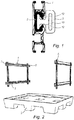
- a cross section is shown of a guiding rail (1) with an insert (2), appearing in solid black, and a gliding element (3).
- Both the insert and the recess of the guiding rail are largely C-shaped or U-shaped.
- the lips (12) of the insert (2) fold inwards towards the recess of the guiding rail and are bent along the recess of the guiding rail. Said lips are preventing that the foot of the gliding element (3) can be removed from the recess of the insert (2), hence the gliding elements are engaged with the insert of the guiding rails.
- the foot of the gliding element (3) can be introduced in the recess of the guiding rail (1) on a position the insert is not provided.
- the dunnage is mounted on the gliding elements either by means of dunnage supports, which comprise plastic strut bars, or by means of textile (or other flexible) connections. These textile connections are provided with a textile band inserted in the slot (13) of the gliding element (3) and sewed or stitched on said pocket. Moreover, the textile connections can be directly integrated in the flexible material of the dunnage.
- Fig. 2 a schematic view of a transporting device according to an embodiment of the current invention is illustrated, omitting the side walls of the transporting device to demonstrate the arrangement of the rails (1) with inserts (2).
- the base (5) of the transporting device is indicating the size of the transporting device.
- Gliding elements (3) are positioned in the insert (2), allowing easy manipulation along the rails with low friction.
- Two sets of rails (1) are provided, hence the device is suitable for the arrangement of two levels of dunnage, as further demonstrated in Fig. 5 .
- the hook elements (6) are provided to place the system with rails in the transport device, allowing easy manipulation of the rail system.
- the rail system can be attached directly to the side walls of the device, for instance by means of screws.
- the guiding rails (1) with inserts (2) are closed by means of an end cap (7), inhibiting the removal of the gliding elements.
- Fig. 3 the cross section of an insert (2) with a transversal division (8) and two lips (12) is shown.
- the lips bend slightly inwards towards the recess, resulting in an approximately J-shaped insert component.
- the components can be clamped in the recess of the latter.
- the two parts of the insert can be connected by a clicking mechanism that can be optionally provided along the division line.
- FIG. 4 an orthographic view is shown of an insert (2) with a division line (8) and lips (12).
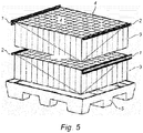
- a schematic view is shown of an embodiment of a transport device with a base (5) and dunnage (9) provided with dunnage supports (4), manufactured from materials comprising hard plastic.
- the dunnage can also be self-supportive, hence lacking a solid dunnage support.
- Two levels of dunnage (9) are mounted on the two sets of guiding rails (1) with inserts (2).
- inserts (2) To illustrate the difference between the guiding rail (1) and the insert (2), on the left side of the lower dunnage (9) and on the right side of the upper dunnage (9), only the insert is presented, without the guiding rail.
- the insert (2) will always be mounted in the recess of a guiding rail (1).
- a cross section is shown of an embodiment of a transporting device with base (5) and at least two side panels (11).
- the guiding rails (1) are mounted on the transporting device by means of an attachment system like hooks (6).
- the guiding rails (1) can be attached directly to the container sides (11) by means of screws.
- Gliding elements (3) are placed in the insert and connect the guiding rail (1) with the dunnage (9) by means of a flexible connection like a textile band (14).
- This textile band (14) is inserted in the slot of the gliding elements (3) and is stitched or sewn to the dunnage supports of the flexible pockets.
- This connection (14) can also be integrated in the shape and material of the dunnage.
- the flexible dunnage of this embodiment is manufactured of woven or non-woven textile and is sagging due to the weight of the piece goods.
- No dunnage supports are provided, hence the dunnage is self-supportively mounted between the rails by means of gliding elements.
- Such transport device without dunnage supports is easily collapsible.
- this sagged flexible dunnage is difficult to move along the guiding rails known in the State of the Art.
- the dunnage can effortlessly slide along the guiding rails.
- FIG. 6b a cross section of a similar embodiment of a transporting device with guiding rails (1) provided with a polymer insert (or with friction-reducing coating) is shown.
- this embodiment comprises dunnage supports (4) which are manufactured of a solid material comprising plastic. Therefore, these do not sag due to the weight of the piece goods.
- the transport container is not easily collapsible due to the use of solid strut bars.
- Gliding elements (3) are mounted on both sides of the dunnage supports and inserted in the recess of the guiding rail.
- a detailed cross section of an embodiment of a mounted guiding rail (1) with insert (2) is shown.
- the insert comprises two insert components, transversally divided by a division line (8).
- the guiding rail is attached to the side panel (11) of the transporting device by means of an attachment system (6).
- the guiding rail (1) can be directly screwed on the side panel (11) of the transport device.
- the dunnage (9) is provided with a connection like a textile band (14), which is inserted in the slot (13) of the gliding element (3) and stitched or sewn on the dunnage (9).
- the gliding element (3) is slidably mounted in the insert (2) of the guiding rail (1).
- a detailed view of an embodiment of a guiding rail (1) with insert (2) is presented. Both the distal and proximal ends of the guiding rail (1) are at least partially covered by an end cap (7), inhibiting the gliding elements (3) that are placed in the insert (2) can be removed.
- the dunnage (9) is mounted on the dunnage support (4), which is connected to the insert (2) of the guiding rail (1) by means of a gliding element (3).
- a transport device with a base (5) and side panels (11) is shown.
- the guiding rails (1) with inserts (2) are attached to the side panels (11) by using an attachment system (6), for instance hooks or screws.
- the gliding elements (3) are placed in the insert (2) of the guiding rail (1) and connect the dunnage (9) with the guiding rail (1).
- Some of the dunnage is loaded with piece goods (10), other part of the dunnage (9) is empty and is arranged on one side of the transport device, which is in practice often the side of the operator who is emptying the transport device.
- the width of the accumulated empty dunnage is determined by the width of the gliding elements. For easy removal of the piece goods, it is essential that the operator does not have to reach too far to take the piece goods. Therefore, it is important to limit the width of the gliding elements.
- a cross section of an embodiment of a transport device is presented.
- some dunnage (9) is empty, while other dunnage (9) contains largely two-dimensional or three-dimensional piece goods (10).
- the guiding rail (1) is connected to the transport device with an attachment system (6) and is closed by end caps (7) on both ends.
- the gliding elements (3) are slidably fitted in the insert (2) of the guiding rail and connect the dunnage supports (4) of the suspended pockets (9) with the guiding rails (1).
- the cross section of the suspended pockets is U-shaped in this particular embodiment.
- the suspended pockets can be made of materials comprising woven or non-woven textile, plastic or a combination thereof.
- a detailed view of an embodiment of a guiding rail (1) with insert (2) is presented. Both the distal and proximal ends of the guiding rail (1) are at least partially covered by an end cap (7), inhibiting the gliding elements (3) that are placed in the insert (2) can be removed.
- the dunnage (9) is self-supportively mounted between the guiding rails and is connected to the insert (2) of the guiding rail (1) by means of a gliding element (3).
- a textile band (14) is put in the slot (13) of the gliding element and stitched to the dunnage to connect the gliding element with the dunnage.
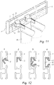
- Fig. 12 a cross section of the different assembly steps of two insert components (2) in the guiding rail (1) according to an embodiment of the current invention is illustrated.
- the first insert component (2) is mounted in the recess of the guiding rail.
- the insert component is clicked and fixed in the upper half of the recess of the guiding rail. Due to the similarity of the shape of the upper part of the recess and the outer shape of the insert component, no additional fixation means are necessary to attach the component in the recess.
- the second insert component is inserted in the lower half of the recess of the guiding rail.
- both insert components are fixed in the guiding rail by clicking in the recess of the guiding rail.
- the guiding rail with mounted insert components is suitable for receiving gliding elements. A division line (8) between the two insert components is still apparent.
- an insert is used to illustrate the use of an intermediate material reducing the friction between the gliding element and the guiding rail. It is equivalent to use a low-friction coating in the recess of the guiding rail. This coating similarly reduces the friction between the gliding element and the guiding rail.
- this document does not intend to limit the shape of the dunnage, the material of the dunnage or the material used to assemble the transport device.
Landscapes
- Engineering & Computer Science (AREA)
- Mechanical Engineering (AREA)
- Details Of Rigid Or Semi-Rigid Containers (AREA)
- Pallets (AREA)
Description
- The invention pertains to the technical field of systems for transportation and storage of goods provided with guiding rails and flexible dunnage.
- Handling units, like boxes, racks or other, provided with guiding rails supporting flexible movable dunnage, are well known in the art. These handling units with dunnage, manufactured of materials like plastic, woven textile or non-woven textile, are used to transport a variety of goods all over the world. It is essential that the dunnage can be easily manipulated by the factory workers, who only have a limited time to fill or empty the dunnage.
- Motivated by its low weight and high tensile strength, aluminum is the standard material to produce such guiding rails. However, aluminum has a high coefficient of kinetic friction, obliging the workers using both hands on the dunnage (one hand on the left side close to the guiding rail, one hand on the right side close to the guiding rail) to slide the dunnage along the rails in the handling units. This issue is in particular, but not only, the case when the flexible dunnage is self-supportive and not supported by a solid dunnage support.
- Transport devices with movable flexible dunnage can be divided in two categories. A first category of such transport devices comprises solid dunnage supports, like strut bars, which are mounted between the guiding rails by means of gliding elements. These transport devices need inventive systems to be collapsible when returned empty, which is a serious drawback for such transport devices. Moreover, when the dunnage support is skewed between the guiding rails, the dunnage can get blocked, due to the large friction between the gliding elements and the recess of the guiding rail. A second category comprises dunnage which is self-supportive, with gliding elements mounted directly on the dunnage or attached by means of a flexible connection like a textile band. Due to the absence of solid bars, these devices are easily collapsible, which is a considerable advantage. However, when manipulating such flexible dunnage lacking a dunnage support, a considerable normal force acts on the gliding element, which results in a large friction and often a blockage of the dunnage.
- Hence, there remains a need in the art for an improved transport system with guiding rails and movable dunnage with or without solid dunnage supports, enabling easy manipulation of the dunnage along the guiding rails.
-
US 2013/0175912 A1 discloses a guiding rail according to the preamble ofclaim 1 and a container according to the preamble ofclaim 9. The present invention aims to resolve at least some of the problems mentioned above. The invention thereto aims to provide an improved guiding rail, both inexpensive, enabling easy and effortless manipulation of the dunnage with or without dunnage supports and easy to install. In particular, the object of the current invention allows a one-hand operation when moving the dunnage in the box, which enhances greatly the efficiency of the operators of such devices. - The present invention provides an improved guiding rail which can be used in storing and transporting devices provided with dunnage, which can be easily and effortlessly moved along the guiding rails, preferably by a one-hand operation.
- In a first aspect, the present invention discloses a guiding rail according to
claim 1. The guiding rail is provided with a recess in the longitudinal direction of said rail, whereby said recess is at least partially provided with an intermediate material. Said intermediate material is in the form of a polymer insert or in the form of a coating added during a painting and/or anodization process. The intermediate material allows easy one-handed manipulation of the flexible dunnage along the guiding rails by pulling or pushing the dunnage, even when a force is applied centrally on the dunnage. - In a second aspect, the present invention provides a container according to
claim 9 provided with such guiding rails provided with an intermediate material as described above. -
- In
Figure 1 a cross section of a polymer insert according to an embodiment of the current invention is shown as mounted in the guiding rail. A gliding element is also provided. - In
Figures 2 and5 , schematic views of transporting devices according to an embodiment of the current invention with guiding rails are presented. - In
Figures 3 and 4 , an insert according to an embodiment of the current invention with a division line is presented. - In
Figure 6 cross sections of a transporting box according to an embodiment of the current invention with flexible dunnage are shown, both with flexible dunnage being self-supportive (Fig. 6a ) and with dunnage supports like solid strut bars (Fig. 6b ). -
Figures 7 and 8 present detailed views on the mounting of the dunnage by means of gliding elements in the insert of the guiding rail according to an embodiment of the current invention. -
Figure 9 shows a transport device according to an embodiment of the current invention provided with guiding rails with a polymer insert. -
Figure 10 shows a cross section of a transport device according to an embodiment of the current invention provided with guiding rails with a polymer insert. -
Figure 11 presents a detailed view on the direct mounting of the gliding elements on the self-supportive dunnage. The gliding elements are positioned in the insert of the guiding rails according to an embodiment of the current invention. -
Figure 12 illustrates the different assembly steps to install two insert components in the recess of a guiding rail according to an embodiment of the current invention. - The present invention concerns an improved guiding rail which can be used in storing and transporting handling units provided with guiding rails and flexible dunnage. This flexible dunnage can be self-supportively mounted between the guiding rails by means of gliding elements at both ends. Alternatively, the flexible dunnage can be provided with at least one solid dunnage support, to which gliding elements are provided. These gliding elements are placed in the recess of the guiding rail. This document discloses how the recess of the guiding rail is at least partially provided with an intermediate material. The intermediate material enables easy manipulation of the dunnage along the guiding rail by pushing or pulling, even with one hand in the center of the dunnage.
- Unless otherwise defined, all terms used in disclosing the invention, including technical and scientific terms, have the meaning as commonly understood by one of ordinary skill in the art to which this invention belongs. By means of further guidance, term definitions are included to better appreciate the teaching of the present invention.
- As used herein, the following terms have meanings as described below.
- The term "dunnage" refers to the assembly of one or more pockets mounted in the transport device. The dunnage can be suspended between the rails by means of a dunnage support, which connects the dunnage with the guiding rails by means of gliding elements. Said dunnage support comprises a strut bar manufactured of materials comprising hard or soft plastic. Alternatively, the flexible dunnage can be suspended between the guiding rails without the use of a dunnage support. In this case, the dunnage is self-supportive and the gliding elements are mounted directly on the dunnage, for instance by means of a flexible connection like a textile band, which is moved in the slot of the gliding element and stitched or sewn to the flexible dunnage for fixation.
- The term "to be slidably fitted in a rail" means that an element is fitted in the rail, but it is able to move along the recess of the rail.
- In a first aspect, this current invention discloses a guiding rail, provided with a recess in the longitudinal direction of the rail. This rail is suitable for receiving gliding elements of a movable dunnage structure like suspended pockets. To improve the ease of manipulation of said dunnage, an intermediate material is provided to the recess of the guiding rail. This intermediate material is at least partially covering the recess of the guiding rail, but can also completely cover the recess of the guiding rail. The cross section of the recess of said guiding rail can be approximately U-shaped or C-shaped. Said guiding rails are manufactured of materials comprising aluminum, steel, plastic or a combination thereof.
- As a first alternative, the invention provides an intermediate material in the form of a polymer insert that can be plugged in in the recess along the longitudinal direction of a guiding rail. The insert covers the recess at least partially along its length, but can also span the entire length of said recess. Gliding elements can be slidably fitted in the insert and interconnect the insert of the guiding rail and the dunnage. The insert comprises lips suitable for partly enclosing said gliding element, inhibiting the removal of the gliding element from the insert. The lips of the insert fold inwards towards the recess of the guiding rail and are bent along the edges of the recess of guiding rail. Both the distal and the proximal end of the guiding rail are at least partially covered by an end cap, closing the recess of the insert and thus preventing the loss of the gliding elements. These improved guiding rails are specifically designed for use in transporting devices with suspended pockets, but can also be applied in other systems with guiding rails. Therefore, the use of said inserts in guiding rails is not limited to the examples provided in the text.
- In a preferred embodiment of the invention, the insert comprises at least one division along a transversal line, hence the insert can be subdivided in at least two components. Inserts are often long and can be slightly curved. It is not straightforward to slide such long insert along the recess from the proximal end to the distal end of the guiding rail, as the curvature of the insert generates tension during installation. Alternatively, several short inserts can be placed in the recess of the long guiding rail and cover as such the entire length of the recess. However, it is necessary to partly disassemble the transport device and to remove the end caps to install such inserts. This is a highly inconvenient and time-consuming process. The installation process of said insert components with a division along the transversal line is much more convenient, because the shape of the recess of the guiding rail and the shape of the insert components allow that the insert components are clicked in the recess of the guiding rail without disassembling the transport device or removing the end caps of the guiding rails.
- In a preferred embodiment, a portion of the guiding rail is insert-free. Said portion is preferentially at the distal or proximal end of the guiding rail. This insert-free opening allows installing the gliding elements in the guiding rails without disassembling the transport device, because the opening of the recess of the guiding rails is large enough to insert the gliding elements. Once the gliding element is included in the recess of the rail, it can be moved further into the insert present in the guiding rail. The lips of the insert impede the removal of the gliding element from the insert, because the opening between the lips is smaller than the foot of the gliding element. Once the gliding elements of the dunnage are installed via the insert-free opening of the guiding rail, a blocking element can be mounted on the insert-free position of the guiding rail, preventing the escape of the gliding elements when moving the dunnage along the guiding rails.
- In an embodiment, the insert is by preference manufactured of a polymer with a low friction coefficient. As a consequence, the suspended pockets can be easily manipulated along the guiding rails in transporting boxes by pulling or pushing the dunnage in the center with one hand, even if the dunnage is not supported by bars and is flexible or bendable. In the transport devices known in the state of the art, moving suspended pockets, especially those without solid dunnage supports, along the guiding rails can be complicated, because the gliding elements get blocked in the guiding rails, especially when only one hand is used in the center of the dunnage support. Therefore, two hands are necessary to move the dunnage of current transport devices, applying one hand on the left side and one hand on the right side of the dunnage support, both hands close to the guiding rail on each side. This is a big disadvantage and hampers efficient work.
- The polymer used for the insert has by preference a density of between 0.9 and 1.5 g/cm3, but preferentially a density of at least about 0.91 g/cm3. The tensile stress of said polymer ranges between 18 and 25 N/mm2, but is preferentially larger than about 19 N/mm2. Furthermore, said polymer has an elongation at break between 45% and 60%, preferentially larger than 50%. The E-modulus of the polymer covers values between 650 N/mm2 and 800 N/mm2 and is preferentially larger than 700 N/mm2. The polymer requires between 4 and 5 N/mm2 compression stress at 1% nominal upset, preferentially 4.5 N/mm2 compression stress. The polymer also needs a compression stress between 6 N/mm2 and 10 N/mm2, preferentially 8 N/mm2, at a nominal upset of 2%. Finally, the polymer needs a compression stress between 12 N/mm2 and 16 N/mm2 at 5% nominal upset. Additionally, the polymer requires a notched impact stress between 100 and 150, preferentially larger than 118. The polymer has a ball pressure hardness between 35 N/mm2 and 45 N/mm2, preferentially about 39 N/mm2. The polymer has a Shore D hardness between 55 and 70, preferentially above 60, and, an abrasion resistance (measured with a Sand Slurry test) between 70% and 90%, preferentially about 80%.
- It was found by the inventors of the current invention that polymers complying with one or more ratios as mentioned above, were proven to be particularly beneficial in the framework of the current invention.
- In an embodiment, the polymer insert comprises a polymer selected from polyolefins such as High-density polyethylene (HDPE), Ultra-high-molecular-weight polyethylene (UHMWPE), Medium density polyethylene (MDPE), polypropylene, polyurethane, polystyrene, cross-linked polyethylene (PEX or XLPE), polyoxymethylene (POM), or lubricated or modified versions of any of the polyolefins stated above to create lower friction coefficients.
- In a second alternative, the intermediate material provided between the recess of the guiding rail and the gliding elements comprises a coating added during a painting and/or anodizing process to the recess of the guiding rail. The coating covers the recess at least partially, but can also completely cover the recess. Lips are provided at the edges of the coated recess of the guiding rail, bending inwards towards the recess. These lips are enclosing the gliding elements and prevent the removal of said gliding elements. An end cap covering at least partially the recess of the guiding rail is provided at both ends of the guiding rail. The gliding elements mounted in the coated recess of the guiding rail allow the uncomplicated manipulation of the flexible dunnage.
- The painting and/or anodization layer is applied with a thickness between 5 and 200 micron, preferentially between 10 and 150 micron. In an embodiment, the coating can comprise a polymer like polytetrafluoroethylene (also known as Teflon), WS2 (Tungsten disulfide) or lubricant paint. In this case, no polymer insert is used, but due to the properties of the polymer, the gliding element can move along the guiding rails without large amounts of friction. Due to the lack of an insert, lips are provided on the guiding rail, preventing the gliding elements of being removed from the recess of the guiding rail.
- The guiding rails are made of materials comprising aluminum, plastic, steel or a combination thereof. These materials are frequently used to produce such rails, because of their low weight and high tensile strength. The insert is manufactured of a polymer with a kinetic friction coefficient between 0 and 0.12 in dry condition. Preferentially, the coefficient of friction between 0 and 0.1, more than ten times lower than the friction coefficient of aluminum. Due to the properties of the polymer of the insert or the recess coating, the dunnage can be easily manipulated along the guiding rails, in contrast to the complicated sliding of the dunnage in current transport devices with aluminum, plastic or steel guiding rails.
- In a particularly preferred embodiment, the gliding elements mounted on the dunnage or on the dunnage supports are replaceable. These elements can be fragile and can require replacement after multiple use of the transport system, especially when heavy goods are carried in the dunnage. Moreover, if the inserts are innovated and are provided with a different improved opening, it is possible to also alter the gliding element. The replacement process of both the insert and the gliding element is fast and inexpensive, especially in the case the insert has a division along a transversal line as described above and the insert components can be clicked in the guiding rail without the need to disassemble the transport device. Further costs are reduced, because the guiding rails do not need replacement and the installation of the innovative insert can be performed without replacing the transporting boxes.
- In an alternative embodiment, the foot of a gliding element has a width smaller than twice the height of the foot of said element. Preferentially the width of the foot is smaller than the height of the foot of the gliding element. Hereby, the foot of the gliding element refers to that part of the gliding element that is introduced in the insert of the guiding rail or in the coated recess of the guiding rail. The width of said foot involves the size of the foot parallel to the guiding rail once the gliding element is mounted (hence parallel to the moving direction). The height refers to the vertical size of the foot once mounted in the horizontal guiding rail (hence orthogonal to the moving direction). The width of the gliding element is important when taking the piece goods out of the transport device: when the piece goods are removed, the operator closes the dunnage and slides the empty dunnage towards the proximal end of the guiding rail. Therefore, empty dunnage is accumulating on the side of the operator while emptying the dunnage and the distance to the closest dunnage loaded with piece goods is increasing. This is highly inconvenient for the operator, who can suffer back pains if it is necessary to reach far for the piece goods. The width of the emptied dunnage is determined by the width of the gliding elements, hence the smaller the width of the gliding elements, the smaller the width of the accumulated emptied dunnage and the more convenient the operator can remove the piece goods.
- The invention also discloses a device, like a handling unit such as a container, a rack or other, used for holding product therein during storage and shipment, the product being two-dimensional or three-dimensional piece goods. The container comprises a bottom and at least two sides, erecting from said bottom, and at least one set of guiding rails supported by the container sides. A lid can be provided to cover the upper side of the container. The container can be manufactured of materials comprising steel (e.g. to form a rack), plastic (e.g. to form a box), wood (e.g. to form a pallet) or a combination thereof. Gliding elements are engaged with and slidable along a longitudinal recess of said guiding rails. A dunnage structure is movably coupled at both sides to the container by means of the gliding elements and operable for being slid along the guiding rails to vary the position of the dunnage structure and to receive product within the container. The dunnage can be self-supportive or can be mounted on solid dunnage supports, like strut bars. The recess of said guiding rails is at least partially provided with an intermediate material in order to facilitate the manipulation of the dunnage along the guiding rails. The intermediate material comprises a polymer insert or a coating added during a painting and/or anodization process, as described above.
- In a possible embodiment of the invention, the dunnage comprises flexible pockets having U-shaped cross sections, suitable for storing and transporting flat, substantially two-dimensional or three-dimensional objects. The dunnage can be supported by at least one dunnage support provided with gliding elements on both sides and manufactured from solid materials like hard plastic. Alternatively, the dunnage can be self-supportive and the gliding elements can be attached directly to the dunnage. The flexible dunnage is made of materials comprising plastic, woven textile, non-woven textile or a combination thereof. The guiding rails are provided over the entire length with an intermediate material like a polymer insert, plugged into the recess of said guiding rails. The gliding elements are placed in the opening of the insert and enable moving the dunnage along the guiding rails without suffering a disturbing amount of friction. Alternatively, a coating can be added during the painting and/or anodization process of the recess of the guiding rail, whereby the friction during the manipulation of dunnage is also vastly reduced. Said coating can be applied by any technique available in the State of the art known by the skilled person. This way the transported goods can be easily stored and arranged in the dunnage of the box, optimizing the use of available storage space. As a consequence, more goods can be transported within the same volume or container, reducing the costs of shipping for a factory. Due to the low friction when moving the dunnage, significant time savings can be achieved and the transport device is more user friendly.
- In a preferred embodiment, said transport device is foldable or collapsible before and after use. Methods and techniques to fold the reusable and returnable containers are well known in the State of the Art. Such containers for holding product therein during shipment and subsequently being returned generally empty of product for reuse comprise a body configured for being manipulated into an erected position for containing a product placed therein during shipment and for subsequently being manipulated into a collapsed position for reducing the size of the container for return. An integrated dunnage structure is coupled to the body and is operable for moving into an engagement position when the container body is erected to thereby engage a product placed in the container for shipment. The dunnage structure is further operable for moving into a relaxed position when the container body is collapsed so that the container and dunnage structure may be returned together for reuse. The container provides reusable dunnage which is usable with the container when it is shipped and subsequently remains with the container when it is returned for being reused when the container is again shipped. In a preferred embodiment, pliable dunnage pouches are suspended in the container and collapse when the container is collapsed. The dunnage has to be manipulated regularly in these collapsible containers. Therefore, the use of a guiding rail with an intermediate material in the recess, like a polymer insert or a coated recess, are advantageous in this type of containers.
- The solid dunnage supports can be produced of materials comprising plastic. The dunnage is manufactured from flexible materials, comprising textile or plastic or a combination thereof. In a particular embodiment, this flexible dunnage has a U-shaped cross section. However, this document is not intended to limit the material or the shape of the dunnage.
- The invention is further described by the following non-limiting examples which further illustrate the invention, and are not intended to, nor should they be interpreted to, limit the scope of the invention.
- In what follows, the different figures are described in more detail.
- In
Fig. 1 a cross section is shown of a guiding rail (1) with an insert (2), appearing in solid black, and a gliding element (3). Both the insert and the recess of the guiding rail are largely C-shaped or U-shaped. The lips (12) of the insert (2) fold inwards towards the recess of the guiding rail and are bent along the recess of the guiding rail. Said lips are preventing that the foot of the gliding element (3) can be removed from the recess of the insert (2), hence the gliding elements are engaged with the insert of the guiding rails. In a preferred embodiment, the foot of the gliding element (3) can be introduced in the recess of the guiding rail (1) on a position the insert is not provided. The dunnage is mounted on the gliding elements either by means of dunnage supports, which comprise plastic strut bars, or by means of textile (or other flexible) connections. These textile connections are provided with a textile band inserted in the slot (13) of the gliding element (3) and sewed or stitched on said pocket. Moreover, the textile connections can be directly integrated in the flexible material of the dunnage. - In
Fig. 2 a schematic view of a transporting device according to an embodiment of the current invention is illustrated, omitting the side walls of the transporting device to demonstrate the arrangement of the rails (1) with inserts (2). The base (5) of the transporting device is indicating the size of the transporting device. Gliding elements (3) are positioned in the insert (2), allowing easy manipulation along the rails with low friction. Two sets of rails (1) are provided, hence the device is suitable for the arrangement of two levels of dunnage, as further demonstrated inFig. 5 . The hook elements (6) are provided to place the system with rails in the transport device, allowing easy manipulation of the rail system. Alternatively, the rail system can be attached directly to the side walls of the device, for instance by means of screws. The guiding rails (1) with inserts (2) are closed by means of an end cap (7), inhibiting the removal of the gliding elements. - In
Fig. 3 the cross section of an insert (2) with a transversal division (8) and two lips (12) is shown. The lips bend slightly inwards towards the recess, resulting in an approximately J-shaped insert component. To install the components of the insert in the recess of the guiding rail, the components can be clamped in the recess of the latter. In an alternative embodiment, the two parts of the insert can be connected by a clicking mechanism that can be optionally provided along the division line. - In
Fig. 4 an orthographic view is shown of an insert (2) with a division line (8) and lips (12). - In
Fig. 5 a schematic view is shown of an embodiment of a transport device with a base (5) and dunnage (9) provided with dunnage supports (4), manufactured from materials comprising hard plastic. The dunnage can also be self-supportive, hence lacking a solid dunnage support. Two levels of dunnage (9) are mounted on the two sets of guiding rails (1) with inserts (2). To illustrate the difference between the guiding rail (1) and the insert (2), on the left side of the lower dunnage (9) and on the right side of the upper dunnage (9), only the insert is presented, without the guiding rail. However, in practice, the insert (2) will always be mounted in the recess of a guiding rail (1). - In
Fig. 6a a cross section is shown of an embodiment of a transporting device with base (5) and at least two side panels (11). The guiding rails (1) are mounted on the transporting device by means of an attachment system like hooks (6). Similarly, the guiding rails (1) can be attached directly to the container sides (11) by means of screws. Gliding elements (3) are placed in the insert and connect the guiding rail (1) with the dunnage (9) by means of a flexible connection like a textile band (14). This textile band (14) is inserted in the slot of the gliding elements (3) and is stitched or sewn to the dunnage supports of the flexible pockets. This connection (14) can also be integrated in the shape and material of the dunnage. The flexible dunnage of this embodiment is manufactured of woven or non-woven textile and is sagging due to the weight of the piece goods. No dunnage supports are provided, hence the dunnage is self-supportively mounted between the rails by means of gliding elements. Such transport device without dunnage supports is easily collapsible. However, this sagged flexible dunnage is difficult to move along the guiding rails known in the State of the Art. However, due to the inclusion of the insert in the guiding rail (or alternatively due to the application of coating on the recess of the guiding rail), the dunnage can effortlessly slide along the guiding rails. - In
Fig. 6b a cross section of a similar embodiment of a transporting device with guiding rails (1) provided with a polymer insert (or with friction-reducing coating) is shown. However, this embodiment comprises dunnage supports (4) which are manufactured of a solid material comprising plastic. Therefore, these do not sag due to the weight of the piece goods. However, the transport container is not easily collapsible due to the use of solid strut bars. Gliding elements (3) are mounted on both sides of the dunnage supports and inserted in the recess of the guiding rail. - In
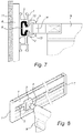
Fig. 7 , a detailed cross section of an embodiment of a mounted guiding rail (1) with insert (2) is shown. The insert comprises two insert components, transversally divided by a division line (8). The guiding rail is attached to the side panel (11) of the transporting device by means of an attachment system (6). In an alternative embodiment, the guiding rail (1) can be directly screwed on the side panel (11) of the transport device. The dunnage (9) is provided with a connection like a textile band (14), which is inserted in the slot (13) of the gliding element (3) and stitched or sewn on the dunnage (9). The gliding element (3) is slidably mounted in the insert (2) of the guiding rail (1). - In
Fig. 8 , a detailed view of an embodiment of a guiding rail (1) with insert (2) is presented. Both the distal and proximal ends of the guiding rail (1) are at least partially covered by an end cap (7), inhibiting the gliding elements (3) that are placed in the insert (2) can be removed. The dunnage (9) is mounted on the dunnage support (4), which is connected to the insert (2) of the guiding rail (1) by means of a gliding element (3). - In
Fig. 9 an embodiment of a transport device with a base (5) and side panels (11) is shown. The guiding rails (1) with inserts (2) are attached to the side panels (11) by using an attachment system (6), for instance hooks or screws. The gliding elements (3) are placed in the insert (2) of the guiding rail (1) and connect the dunnage (9) with the guiding rail (1). Some of the dunnage is loaded with piece goods (10), other part of the dunnage (9) is empty and is arranged on one side of the transport device, which is in practice often the side of the operator who is emptying the transport device. Note that the width of the accumulated empty dunnage is determined by the width of the gliding elements. For easy removal of the piece goods, it is essential that the operator does not have to reach too far to take the piece goods. Therefore, it is important to limit the width of the gliding elements. - In
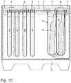
Fig. 10 , a cross section of an embodiment of a transport device is presented. As inFig. 9 , some dunnage (9) is empty, while other dunnage (9) contains largely two-dimensional or three-dimensional piece goods (10). The guiding rail (1) is connected to the transport device with an attachment system (6) and is closed by end caps (7) on both ends. The gliding elements (3) are slidably fitted in the insert (2) of the guiding rail and connect the dunnage supports (4) of the suspended pockets (9) with the guiding rails (1). The cross section of the suspended pockets is U-shaped in this particular embodiment. Two types of suspended pockets are illustrated: on the left side of the figure, the different suspended pockets are independent of each other, while on the right side of the figure, the suspended pockets are connected and share one wall. The suspended pockets can be made of materials comprising woven or non-woven textile, plastic or a combination thereof. - In
Fig. 11 a detailed view of an embodiment of a guiding rail (1) with insert (2) is presented. Both the distal and proximal ends of the guiding rail (1) are at least partially covered by an end cap (7), inhibiting the gliding elements (3) that are placed in the insert (2) can be removed. The dunnage (9) is self-supportively mounted between the guiding rails and is connected to the insert (2) of the guiding rail (1) by means of a gliding element (3). A textile band (14) is put in the slot (13) of the gliding element and stitched to the dunnage to connect the gliding element with the dunnage. - In
Fig. 12 a cross section of the different assembly steps of two insert components (2) in the guiding rail (1) according to an embodiment of the current invention is illustrated. In the first step, the first insert component (2) is mounted in the recess of the guiding rail. In the second step, the insert component is clicked and fixed in the upper half of the recess of the guiding rail. Due to the similarity of the shape of the upper part of the recess and the outer shape of the insert component, no additional fixation means are necessary to attach the component in the recess. In the third step, the second insert component is inserted in the lower half of the recess of the guiding rail. In the last step, both insert components are fixed in the guiding rail by clicking in the recess of the guiding rail. The guiding rail with mounted insert components is suitable for receiving gliding elements. A division line (8) between the two insert components is still apparent. - The numbers used in the figures referring to the different components of the invention are listed below.
- 1. Guiding rail
- 2. Insert
- 3. Gliding element
- 4. Dunnage support, like solid strut bar
- 5. Base of a transporting device like a box or container
- 6. Attachment system for mounting the rails
- 7. Removable end cap
- 8. Division along the transversal line of the insert
- 9. Dunnage structure, like transport bags or suspended pockets
- 10. Piece goods
- 11. Side panel
- 12. Lip of the insert
- 13. Slot of the gliding element
- 14. Flexible connection, like a textile band, between the gliding element and the dunnage
- It is supposed that the present invention is not restricted to any form of realization described previously and that some modifications can be added to the presented example of fabrication without reappraisal of the appended claim. In the figures, an insert is used to illustrate the use of an intermediate material reducing the friction between the gliding element and the guiding rail. It is equivalent to use a low-friction coating in the recess of the guiding rail. This coating similarly reduces the friction between the gliding element and the guiding rail.
- Furthermore, this document does not intend to limit the shape of the dunnage, the material of the dunnage or the material used to assemble the transport device.
Claims (12)
- Guiding rail (1) provided with one or more gliding elements (3), suitable for supporting a dunnage structure (9) in a transport and/or storage device, whereby said rail (1) is provided with a recess in the longitudinal direction of said rail (1), which recess is at least partially provided with an intermediate material, characterized in that the intermediate material comprises a polymer insert (2), or a coating added during a painting and/or anodization process, the coating completely covering the recess, wherein at least one of said gliding elements (3) is slidably fitted in said insert (2) or in said coated recess, and wherein:- in case of the intermediate material insert (2), said insert (2) comprises lips (12), and- in case of the intermediate material coating, said guiding rail (1) comprises lips partly enclosing the coated recess,wherein in both cases said lips partly enclose said at least one gliding element (3), inhibiting removal of said at least one gliding element (3).
- Guiding rail according to Claim 1, characterized in that said intermediate material comprises the insert (2), said insert (2) being divided in at least two components along a transversal division line (8) of said insert (2).
- Guiding rail (1) according to Claim 2, characterized in that said polymer insert (2) comprises a polymer selected from polyolefins such as High-density polyethylene (HDPE), Ultra-high-molecular-weight polyethylene (UHMWPE), Medium density polyethylene (MDPE), polypropylene, polyurethane, polystyrene, cross-linked polyethylene (PEX or XLPE), polyoxymethylene (POM) or lubricated or modified versions of any of said polyolefins.
- Guiding rail (1) according to any of the preceding claims, characterized in that said intermediate material covers the entire length of said recess.
- Guiding rail (1) according to any of the preceding claims, characterized in that the cross section of said recess is U-shaped or C-shaped.
- Guiding rail (1) according to any of the preceding claims, characterized in that said guiding rail (1) is manufactured of aluminum, plastic or steel or a combination thereof.
- Guiding rail according to any of the previous claims, characterized in that the one or more gliding elements (3) are replaceable.
- Guiding rail (1) according to any of the previous claims, characterized in that the distal and proximal ends of the guiding rail (1) are at least partially covered by an end cap (7).
- Container for holding product (10) therein during shipment, the container comprising:a bottom and at least two sides (11), erecting from said bottom;at least one set of guiding rails (1) supported by the container sides (11);one or more gliding elements (3) being engaged with and slidable along the guiding rails (1);a dunnage structure (9) that is movably coupled to the container by means of the gliding elements (3) and operable for being slid along the guiding rails (1) to vary the position of the dunnage structure (9) and to receive product (10) within the container,characterized in that said guiding rails (1) and one or more gliding elements (3) are according to any of the previous claims 1-8.
- Container for holding product (10) therein during shipment according to Claim 9, characterized in that said dunnage (9) is self-supportive, with said one or more gliding elements (3) attached directly to the dunnage (9), or said dunnage (9) is supported by a dunnage support (4), with said one or more gliding elements (3) mounted on both sides of said dunnage support (4).
- Container for holding product (10) therein during shipment according to Claim 9, characterized in that said dunnage support (4) is produced of solid materials comprising hard plastic.
- Container for holding product therein during shipment according to any of claims 9-11, characterized in that the container is foldable or collapsible before and after use, whereby the container comprises opposing side structures (11) that are moveable and can be manipulated into an erected position so that the container may contain a product (10) placed therein during shipment and for subsequently being moved inwardly toward each other into a collapsed position for reducing the size of the container for return.
Priority Applications (1)
| Application Number | Priority Date | Filing Date | Title |
|---|---|---|---|
| PL16709360T PL3371069T3 (en) | 2015-11-06 | 2016-03-08 | Guiding rail provided with intermediate material and container provided with such guiding rail |
Applications Claiming Priority (2)
| Application Number | Priority Date | Filing Date | Title |
|---|---|---|---|
| CZ2015-31737U CZ31259U1 (en) | 2015-11-06 | 2015-11-06 | A guide bracket fitted with an embedded material and a device equipped with such a guide bracket |
| PCT/EP2016/054940 WO2017076516A1 (en) | 2015-11-06 | 2016-03-08 | Guiding rail provided with intermediate material and container provided with such guiding rail |
Publications (2)
| Publication Number | Publication Date |
|---|---|
| EP3371069A1 EP3371069A1 (en) | 2018-09-12 |
| EP3371069B1 true EP3371069B1 (en) | 2020-05-06 |
Family
ID=58661824
Family Applications (1)
| Application Number | Title | Priority Date | Filing Date |
|---|---|---|---|
| EP16709360.8A Active EP3371069B1 (en) | 2015-11-06 | 2016-03-08 | Guiding rail provided with intermediate material and container provided with such guiding rail |
Country Status (6)
| Country | Link |
|---|---|
| US (1) | US10858149B2 (en) |
| EP (1) | EP3371069B1 (en) |
| CZ (1) | CZ31259U1 (en) |
| HU (1) | HUE050361T2 (en) |
| PL (1) | PL3371069T3 (en) |
| WO (1) | WO2017076516A1 (en) |
Cited By (1)
| Publication number | Priority date | Publication date | Assignee | Title |
|---|---|---|---|---|
| DE102022204330B4 (en) | 2022-05-02 | 2026-03-12 | Volkswagen Aktiengesellschaft | High-voltage drive system for a vehicle, as well as a vehicle with a high-voltage drive system |
Families Citing this family (5)
| Publication number | Priority date | Publication date | Assignee | Title |
|---|---|---|---|---|
| CN108341147A (en) * | 2017-09-13 | 2018-07-31 | 中久物流有限公司 | Platform |
| DE202019104028U1 (en) | 2019-03-07 | 2019-09-26 | Conteyor International Nv | Guide rail and transport container |
| US20240409294A1 (en) * | 2019-11-07 | 2024-12-12 | Bradford Company | Rail support assembly for a transportation or storage container |
| BE1028553B1 (en) * | 2020-08-20 | 2022-03-21 | Conteyor Int Nv | STORAGE DEVICE WITH VERTICALLY MOVABLE CURTAIN AND KIT FOR ATTACHING VERTICALLY MOVABLE CURTAINS TO STORAGE DEVICE |
| GB2603940A (en) * | 2021-02-20 | 2022-08-24 | Chep Uk Ltd | Removable shelf for rigid containers for dry goods |
Citations (5)
| Publication number | Priority date | Publication date | Assignee | Title |
|---|---|---|---|---|
| US20060230575A1 (en) | 2005-04-19 | 2006-10-19 | Quanex Corporation | Sliding rail assembly for a sliding panel movable along a track |
| US20060249415A1 (en) | 2005-05-05 | 2006-11-09 | Bradford Company | Container having sliding support members |
| DE102007030079A1 (en) | 2007-06-28 | 2009-01-02 | Geze Gmbh | Sliding door system, has door wing supported in adjusting manner along guide rail by roller carriage and cleaning device is formed as contact-free effective device on bearing surface |
| TWM362658U (en) | 2009-03-18 | 2009-08-11 | Young Master Curtains Entpr Co Ltd | Curtain rail system by single tightening wire |
| US20130175912A1 (en) | 2011-09-06 | 2013-07-11 | Bradford Company | Container Having Sliding Support Assemblies For Supporting Dunnage |
Family Cites Families (9)
| Publication number | Priority date | Publication date | Assignee | Title |
|---|---|---|---|---|
| GB1297230A (en) | 1971-08-16 | 1972-11-22 | ||
| US8308015B2 (en) | 2005-05-05 | 2012-11-13 | Bradford Company | Collapsible container having sliding support member assemblies for supporting dunnage |
| JP2009532308A (en) | 2006-04-03 | 2009-09-10 | スパン テック エルエルシー | Product conveying component with powder coating and method related thereto |
| CN109177531B (en) * | 2012-03-15 | 2020-11-27 | 兰达公司 | Endless flexible belt for printing system |
| US9004307B2 (en) * | 2012-09-14 | 2015-04-14 | Bradford Company | Container having movable support member assemblies for supporting dunnage and movable door |
| US9676548B2 (en) * | 2012-09-14 | 2017-06-13 | Bradford Company | Container having generally L-shaped slotted tracks to facilitate movement of dunnage |
| US9988208B2 (en) * | 2013-09-27 | 2018-06-05 | Bradford Company | Container having padded dunnage supports and straight tracks |
| US9382037B2 (en) | 2013-10-15 | 2016-07-05 | Bradford Company | Container having multiple layers of tracks including at least one non-linear track |
| US9731863B2 (en) * | 2013-11-21 | 2017-08-15 | Bradford Company | Container having multiple levels of slots to facilitate movement of dunnage |
-
2015
- 2015-11-06 CZ CZ2015-31737U patent/CZ31259U1/en not_active IP Right Cessation
-
2016
- 2016-03-08 US US15/773,876 patent/US10858149B2/en active Active
- 2016-03-08 HU HUE16709360A patent/HUE050361T2/en unknown
- 2016-03-08 EP EP16709360.8A patent/EP3371069B1/en active Active
- 2016-03-08 PL PL16709360T patent/PL3371069T3/en unknown
- 2016-03-08 WO PCT/EP2016/054940 patent/WO2017076516A1/en not_active Ceased
Patent Citations (5)
| Publication number | Priority date | Publication date | Assignee | Title |
|---|---|---|---|---|
| US20060230575A1 (en) | 2005-04-19 | 2006-10-19 | Quanex Corporation | Sliding rail assembly for a sliding panel movable along a track |
| US20060249415A1 (en) | 2005-05-05 | 2006-11-09 | Bradford Company | Container having sliding support members |
| DE102007030079A1 (en) | 2007-06-28 | 2009-01-02 | Geze Gmbh | Sliding door system, has door wing supported in adjusting manner along guide rail by roller carriage and cleaning device is formed as contact-free effective device on bearing surface |
| TWM362658U (en) | 2009-03-18 | 2009-08-11 | Young Master Curtains Entpr Co Ltd | Curtain rail system by single tightening wire |
| US20130175912A1 (en) | 2011-09-06 | 2013-07-11 | Bradford Company | Container Having Sliding Support Assemblies For Supporting Dunnage |
Cited By (1)
| Publication number | Priority date | Publication date | Assignee | Title |
|---|---|---|---|---|
| DE102022204330B4 (en) | 2022-05-02 | 2026-03-12 | Volkswagen Aktiengesellschaft | High-voltage drive system for a vehicle, as well as a vehicle with a high-voltage drive system |
Also Published As
| Publication number | Publication date |
|---|---|
| EP3371069A1 (en) | 2018-09-12 |
| CZ31259U1 (en) | 2017-12-04 |
| US10858149B2 (en) | 2020-12-08 |
| US20180319534A1 (en) | 2018-11-08 |
| PL3371069T3 (en) | 2020-11-16 |
| WO2017076516A1 (en) | 2017-05-11 |
| HUE050361T2 (en) | 2020-11-30 |
Similar Documents
| Publication | Publication Date | Title |
|---|---|---|
| EP3371069B1 (en) | Guiding rail provided with intermediate material and container provided with such guiding rail | |
| US10028582B2 (en) | Storage system | |
| US20100066045A1 (en) | Cart | |
| DK2944582T3 (en) | COMBINATION OF A CONTAINER AND A TRAY STAND | |
| US9073665B2 (en) | Container having door assembly and multiple layers of tracks | |
| US9010563B2 (en) | Container having metal outer frame for supporting L-shaped tracks | |
| US9334689B2 (en) | Interior ladder rack | |
| US9004307B2 (en) | Container having movable support member assemblies for supporting dunnage and movable door | |
| US9896116B2 (en) | Wheelbarrow with auxiliary storage | |
| US10189640B2 (en) | Container having generally L-shaped slotted tracks to facilitate movement of dunnage | |
| US9295313B2 (en) | Skid plate for handle | |
| US9969528B2 (en) | Container having door assembly and multiple layers of tracks | |
| US8517320B1 (en) | Quick attachment bracket for securing a first item to a second item | |
| US10131180B1 (en) | Collapsible paint caddy | |
| NO153329B (en) | CONTAINER, SPECIAL FOR AIR TRANSPORT. | |
| US20160083179A1 (en) | Container Having L-Shaped Tracks | |
| US20200122889A1 (en) | Attachable caddy | |
| US9701450B1 (en) | Container for storing small items and related methods | |
| ES2809723T3 (en) | Guide rail provided with intermediate material and container provided with said guide rail | |
| US6216993B1 (en) | Modular storage system | |
| WO2022038569A1 (en) | Storage device with vertically movable curtain and kit for attaching vertically movable curtain to storage device | |
| KR200426281Y1 (en) | Cart-type crater box | |
| JP2005304573A (en) | Container with book support |
Legal Events
| Date | Code | Title | Description |
|---|---|---|---|
| STAA | Information on the status of an ep patent application or granted ep patent |
Free format text: STATUS: THE INTERNATIONAL PUBLICATION HAS BEEN MADE |
|
| PUAI | Public reference made under article 153(3) epc to a published international application that has entered the european phase |
Free format text: ORIGINAL CODE: 0009012 |
|
| STAA | Information on the status of an ep patent application or granted ep patent |
Free format text: STATUS: REQUEST FOR EXAMINATION WAS MADE |
|
| 17P | Request for examination filed |
Effective date: 20180606 |
|
| AK | Designated contracting states |
Kind code of ref document: A1 Designated state(s): AL AT BE BG CH CY CZ DE DK EE ES FI FR GB GR HR HU IE IS IT LI LT LU LV MC MK MT NL NO PL PT RO RS SE SI SK SM TR |
|
| AX | Request for extension of the european patent |
Extension state: BA ME |
|
| DAV | Request for validation of the european patent (deleted) | ||
| DAX | Request for extension of the european patent (deleted) | ||
| STAA | Information on the status of an ep patent application or granted ep patent |
Free format text: STATUS: EXAMINATION IS IN PROGRESS |
|
| 17Q | First examination report despatched |
Effective date: 20190513 |
|
| GRAP | Despatch of communication of intention to grant a patent |
Free format text: ORIGINAL CODE: EPIDOSNIGR1 |
|
| STAA | Information on the status of an ep patent application or granted ep patent |
Free format text: STATUS: GRANT OF PATENT IS INTENDED |
|
| INTG | Intention to grant announced |
Effective date: 20191120 |
|
| GRAS | Grant fee paid |
Free format text: ORIGINAL CODE: EPIDOSNIGR3 |
|
| GRAA | (expected) grant |
Free format text: ORIGINAL CODE: 0009210 |
|
| STAA | Information on the status of an ep patent application or granted ep patent |
Free format text: STATUS: THE PATENT HAS BEEN GRANTED |
|
| AK | Designated contracting states |
Kind code of ref document: B1 Designated state(s): AL AT BE BG CH CY CZ DE DK EE ES FI FR GB GR HR HU IE IS IT LI LT LU LV MC MK MT NL NO PL PT RO RS SE SI SK SM TR |
|
| REG | Reference to a national code |
Ref country code: GB Ref legal event code: FG4D |
|
| REG | Reference to a national code |
Ref country code: CH Ref legal event code: EP Ref country code: AT Ref legal event code: REF Ref document number: 1266389 Country of ref document: AT Kind code of ref document: T Effective date: 20200515 |
|
| REG | Reference to a national code |
Ref country code: IE Ref legal event code: FG4D |
|
| REG | Reference to a national code |
Ref country code: DE Ref legal event code: R096 Ref document number: 602016035678 Country of ref document: DE |
|
| REG | Reference to a national code |
Ref country code: NL Ref legal event code: FP |
|
| REG | Reference to a national code |
Ref country code: LT Ref legal event code: MG4D |
|
| PG25 | Lapsed in a contracting state [announced via postgrant information from national office to epo] |
Ref country code: PT Free format text: LAPSE BECAUSE OF FAILURE TO SUBMIT A TRANSLATION OF THE DESCRIPTION OR TO PAY THE FEE WITHIN THE PRESCRIBED TIME-LIMIT Effective date: 20200907 Ref country code: GR Free format text: LAPSE BECAUSE OF FAILURE TO SUBMIT A TRANSLATION OF THE DESCRIPTION OR TO PAY THE FEE WITHIN THE PRESCRIBED TIME-LIMIT Effective date: 20200807 Ref country code: FI Free format text: LAPSE BECAUSE OF FAILURE TO SUBMIT A TRANSLATION OF THE DESCRIPTION OR TO PAY THE FEE WITHIN THE PRESCRIBED TIME-LIMIT Effective date: 20200506 Ref country code: LT Free format text: LAPSE BECAUSE OF FAILURE TO SUBMIT A TRANSLATION OF THE DESCRIPTION OR TO PAY THE FEE WITHIN THE PRESCRIBED TIME-LIMIT Effective date: 20200506 Ref country code: IS Free format text: LAPSE BECAUSE OF FAILURE TO SUBMIT A TRANSLATION OF THE DESCRIPTION OR TO PAY THE FEE WITHIN THE PRESCRIBED TIME-LIMIT Effective date: 20200906 Ref country code: SE Free format text: LAPSE BECAUSE OF FAILURE TO SUBMIT A TRANSLATION OF THE DESCRIPTION OR TO PAY THE FEE WITHIN THE PRESCRIBED TIME-LIMIT Effective date: 20200506 Ref country code: NO Free format text: LAPSE BECAUSE OF FAILURE TO SUBMIT A TRANSLATION OF THE DESCRIPTION OR TO PAY THE FEE WITHIN THE PRESCRIBED TIME-LIMIT Effective date: 20200806 |
|
| REG | Reference to a national code |
Ref country code: SK Ref legal event code: T3 Ref document number: E 35107 Country of ref document: SK |
|
| PG25 | Lapsed in a contracting state [announced via postgrant information from national office to epo] |
Ref country code: HR Free format text: LAPSE BECAUSE OF FAILURE TO SUBMIT A TRANSLATION OF THE DESCRIPTION OR TO PAY THE FEE WITHIN THE PRESCRIBED TIME-LIMIT Effective date: 20200506 Ref country code: RS Free format text: LAPSE BECAUSE OF FAILURE TO SUBMIT A TRANSLATION OF THE DESCRIPTION OR TO PAY THE FEE WITHIN THE PRESCRIBED TIME-LIMIT Effective date: 20200506 Ref country code: BG Free format text: LAPSE BECAUSE OF FAILURE TO SUBMIT A TRANSLATION OF THE DESCRIPTION OR TO PAY THE FEE WITHIN THE PRESCRIBED TIME-LIMIT Effective date: 20200806 Ref country code: LV Free format text: LAPSE BECAUSE OF FAILURE TO SUBMIT A TRANSLATION OF THE DESCRIPTION OR TO PAY THE FEE WITHIN THE PRESCRIBED TIME-LIMIT Effective date: 20200506 |
|
| REG | Reference to a national code |
Ref country code: HU Ref legal event code: AG4A Ref document number: E050361 Country of ref document: HU |
|
| REG | Reference to a national code |
Ref country code: AT Ref legal event code: MK05 Ref document number: 1266389 Country of ref document: AT Kind code of ref document: T Effective date: 20200506 |
|
| PG25 | Lapsed in a contracting state [announced via postgrant information from national office to epo] |
Ref country code: AL Free format text: LAPSE BECAUSE OF FAILURE TO SUBMIT A TRANSLATION OF THE DESCRIPTION OR TO PAY THE FEE WITHIN THE PRESCRIBED TIME-LIMIT Effective date: 20200506 |
|
| PG25 | Lapsed in a contracting state [announced via postgrant information from national office to epo] |
Ref country code: EE Free format text: LAPSE BECAUSE OF FAILURE TO SUBMIT A TRANSLATION OF THE DESCRIPTION OR TO PAY THE FEE WITHIN THE PRESCRIBED TIME-LIMIT Effective date: 20200506 Ref country code: IT Free format text: LAPSE BECAUSE OF FAILURE TO SUBMIT A TRANSLATION OF THE DESCRIPTION OR TO PAY THE FEE WITHIN THE PRESCRIBED TIME-LIMIT Effective date: 20200506 Ref country code: SM Free format text: LAPSE BECAUSE OF FAILURE TO SUBMIT A TRANSLATION OF THE DESCRIPTION OR TO PAY THE FEE WITHIN THE PRESCRIBED TIME-LIMIT Effective date: 20200506 Ref country code: AT Free format text: LAPSE BECAUSE OF FAILURE TO SUBMIT A TRANSLATION OF THE DESCRIPTION OR TO PAY THE FEE WITHIN THE PRESCRIBED TIME-LIMIT Effective date: 20200506 Ref country code: DK Free format text: LAPSE BECAUSE OF FAILURE TO SUBMIT A TRANSLATION OF THE DESCRIPTION OR TO PAY THE FEE WITHIN THE PRESCRIBED TIME-LIMIT Effective date: 20200506 |
|
| REG | Reference to a national code |
Ref country code: DE Ref legal event code: R026 Ref document number: 602016035678 Country of ref document: DE |
|
| PLBI | Opposition filed |
Free format text: ORIGINAL CODE: 0009260 |
|
| REG | Reference to a national code |
Ref country code: ES Ref legal event code: FG2A Ref document number: 2809723 Country of ref document: ES Kind code of ref document: T3 Effective date: 20210305 |
|
| PLAX | Notice of opposition and request to file observation + time limit sent |
Free format text: ORIGINAL CODE: EPIDOSNOBS2 |
|
| 26 | Opposition filed |
Opponent name: IGOPAK S.R.O. Effective date: 20210203 |
|
| PG25 | Lapsed in a contracting state [announced via postgrant information from national office to epo] |
Ref country code: SI Free format text: LAPSE BECAUSE OF FAILURE TO SUBMIT A TRANSLATION OF THE DESCRIPTION OR TO PAY THE FEE WITHIN THE PRESCRIBED TIME-LIMIT Effective date: 20200506 |
|
| PLBB | Reply of patent proprietor to notice(s) of opposition received |
Free format text: ORIGINAL CODE: EPIDOSNOBS3 |
|
| PG25 | Lapsed in a contracting state [announced via postgrant information from national office to epo] |
Ref country code: MC Free format text: LAPSE BECAUSE OF FAILURE TO SUBMIT A TRANSLATION OF THE DESCRIPTION OR TO PAY THE FEE WITHIN THE PRESCRIBED TIME-LIMIT Effective date: 20200506 |
|
| REG | Reference to a national code |
Ref country code: CH Ref legal event code: PL |
|
| PLCK | Communication despatched that opposition was rejected |
Free format text: ORIGINAL CODE: EPIDOSNREJ1 |
|
| REG | Reference to a national code |
Ref country code: DE Ref legal event code: R100 Ref document number: 602016035678 Country of ref document: DE |
|
| PG25 | Lapsed in a contracting state [announced via postgrant information from national office to epo] |
Ref country code: IE Free format text: LAPSE BECAUSE OF NON-PAYMENT OF DUE FEES Effective date: 20210308 Ref country code: LI Free format text: LAPSE BECAUSE OF NON-PAYMENT OF DUE FEES Effective date: 20210331 Ref country code: LU Free format text: LAPSE BECAUSE OF NON-PAYMENT OF DUE FEES Effective date: 20210308 Ref country code: CH Free format text: LAPSE BECAUSE OF NON-PAYMENT OF DUE FEES Effective date: 20210331 |
|
| PLBN | Opposition rejected |
Free format text: ORIGINAL CODE: 0009273 |
|
| STAA | Information on the status of an ep patent application or granted ep patent |
Free format text: STATUS: OPPOSITION REJECTED |
|
| 27O | Opposition rejected |
Effective date: 20211219 |
|
| P01 | Opt-out of the competence of the unified patent court (upc) registered |
Effective date: 20230507 |
|
| PG25 | Lapsed in a contracting state [announced via postgrant information from national office to epo] |
Ref country code: CY Free format text: LAPSE BECAUSE OF FAILURE TO SUBMIT A TRANSLATION OF THE DESCRIPTION OR TO PAY THE FEE WITHIN THE PRESCRIBED TIME-LIMIT Effective date: 20200506 |
|
| PG25 | Lapsed in a contracting state [announced via postgrant information from national office to epo] |
Ref country code: MK Free format text: LAPSE BECAUSE OF FAILURE TO SUBMIT A TRANSLATION OF THE DESCRIPTION OR TO PAY THE FEE WITHIN THE PRESCRIBED TIME-LIMIT Effective date: 20200506 |
|
| PG25 | Lapsed in a contracting state [announced via postgrant information from national office to epo] |
Ref country code: MT Free format text: LAPSE BECAUSE OF FAILURE TO SUBMIT A TRANSLATION OF THE DESCRIPTION OR TO PAY THE FEE WITHIN THE PRESCRIBED TIME-LIMIT Effective date: 20200506 |
|
| PGFP | Annual fee paid to national office [announced via postgrant information from national office to epo] |
Ref country code: ES Payment date: 20250429 Year of fee payment: 10 |
|
| PGFP | Annual fee paid to national office [announced via postgrant information from national office to epo] |
Ref country code: GB Payment date: 20260324 Year of fee payment: 11 |
|
| PGFP | Annual fee paid to national office [announced via postgrant information from national office to epo] |
Ref country code: DE Payment date: 20260319 Year of fee payment: 11 |
|
| PGFP | Annual fee paid to national office [announced via postgrant information from national office to epo] |
Ref country code: BE Payment date: 20260319 Year of fee payment: 11 Ref country code: RO Payment date: 20260303 Year of fee payment: 11 |
|
| PGFP | Annual fee paid to national office [announced via postgrant information from national office to epo] |
Ref country code: HU Payment date: 20260323 Year of fee payment: 11 Ref country code: NL Payment date: 20260319 Year of fee payment: 11 |
|
| PGFP | Annual fee paid to national office [announced via postgrant information from national office to epo] |
Ref country code: FR Payment date: 20260320 Year of fee payment: 11 |
|
| PGFP | Annual fee paid to national office [announced via postgrant information from national office to epo] |
Ref country code: TR Payment date: 20260303 Year of fee payment: 11 |
|
| PGFP | Annual fee paid to national office [announced via postgrant information from national office to epo] |
Ref country code: CZ Payment date: 20260303 Year of fee payment: 11 |
|
| PGFP | Annual fee paid to national office [announced via postgrant information from national office to epo] |
Ref country code: PL Payment date: 20260227 Year of fee payment: 11 |
|
| PGFP | Annual fee paid to national office [announced via postgrant information from national office to epo] |
Ref country code: SK Payment date: 20260306 Year of fee payment: 11 |