EP3370644B1 - Augenimplantatbehälter - Google Patents
Augenimplantatbehälter Download PDFInfo
- Publication number
- EP3370644B1 EP3370644B1 EP16790424.2A EP16790424A EP3370644B1 EP 3370644 B1 EP3370644 B1 EP 3370644B1 EP 16790424 A EP16790424 A EP 16790424A EP 3370644 B1 EP3370644 B1 EP 3370644B1
- Authority
- EP
- European Patent Office
- Prior art keywords
- implant
- container
- delivery
- delivery device
- housing
- Prior art date
- Legal status (The legal status is an assumption and is not a legal conclusion. Google has not performed a legal analysis and makes no representation as to the accuracy of the status listed.)
- Active
Links
Images


Classifications
-
- A—HUMAN NECESSITIES
- A61—MEDICAL OR VETERINARY SCIENCE; HYGIENE
- A61F—FILTERS IMPLANTABLE INTO BLOOD VESSELS; PROSTHESES; DEVICES PROVIDING PATENCY TO, OR PREVENTING COLLAPSING OF, TUBULAR STRUCTURES OF THE BODY, e.g. STENTS; ORTHOPAEDIC, NURSING OR CONTRACEPTIVE DEVICES; FOMENTATION; TREATMENT OR PROTECTION OF EYES OR EARS; BANDAGES, DRESSINGS OR ABSORBENT PADS; FIRST-AID KITS
- A61F9/00—Methods or devices for treatment of the eyes; Devices for putting in contact-lenses; Devices to correct squinting; Apparatus to guide the blind; Protective devices for the eyes, carried on the body or in the hand
- A61F9/0008—Introducing ophthalmic products into the ocular cavity or retaining products therein
- A61F9/0017—Introducing ophthalmic products into the ocular cavity or retaining products therein implantable in, or in contact with, the eye, e.g. ocular inserts
-
- A—HUMAN NECESSITIES
- A61—MEDICAL OR VETERINARY SCIENCE; HYGIENE
- A61F—FILTERS IMPLANTABLE INTO BLOOD VESSELS; PROSTHESES; DEVICES PROVIDING PATENCY TO, OR PREVENTING COLLAPSING OF, TUBULAR STRUCTURES OF THE BODY, e.g. STENTS; ORTHOPAEDIC, NURSING OR CONTRACEPTIVE DEVICES; FOMENTATION; TREATMENT OR PROTECTION OF EYES OR EARS; BANDAGES, DRESSINGS OR ABSORBENT PADS; FIRST-AID KITS
- A61F2/00—Filters implantable into blood vessels; Prostheses, i.e. artificial substitutes or replacements for parts of the body; Appliances for connecting them with the body; Devices providing patency to, or preventing collapsing of, tubular structures of the body, e.g. stents
- A61F2/02—Prostheses implantable into the body
- A61F2/14—Eye parts, e.g. lenses or corneal implants; Artificial eyes
- A61F2/16—Intraocular lenses
- A61F2/1662—Instruments for inserting intraocular lenses into the eye
-
- A—HUMAN NECESSITIES
- A61—MEDICAL OR VETERINARY SCIENCE; HYGIENE
- A61M—DEVICES FOR INTRODUCING MEDIA INTO, OR ONTO, THE BODY; DEVICES FOR TRANSDUCING BODY MEDIA OR FOR TAKING MEDIA FROM THE BODY; DEVICES FOR PRODUCING OR ENDING SLEEP OR STUPOR
- A61M25/00—Catheters; Hollow probes
- A61M25/01—Introducing, guiding, advancing, emplacing or holding catheters
- A61M25/09—Guide wires
-
- A—HUMAN NECESSITIES
- A61—MEDICAL OR VETERINARY SCIENCE; HYGIENE
- A61F—FILTERS IMPLANTABLE INTO BLOOD VESSELS; PROSTHESES; DEVICES PROVIDING PATENCY TO, OR PREVENTING COLLAPSING OF, TUBULAR STRUCTURES OF THE BODY, e.g. STENTS; ORTHOPAEDIC, NURSING OR CONTRACEPTIVE DEVICES; FOMENTATION; TREATMENT OR PROTECTION OF EYES OR EARS; BANDAGES, DRESSINGS OR ABSORBENT PADS; FIRST-AID KITS
- A61F2250/00—Special features of prostheses classified in groups A61F2/00 - A61F2/26 or A61F2/82 or A61F9/00 or A61F11/00 or subgroups thereof
- A61F2250/0058—Additional features; Implant or prostheses properties not otherwise provided for
- A61F2250/0067—Means for introducing or releasing pharmaceutical products into the body
- A61F2250/0068—Means for introducing or releasing pharmaceutical products into the body the pharmaceutical product being in a reservoir
Definitions
- the subject matter described herein relates to an implant container that can contain an ocular implant and assist with loading the ocular implant onto an implant delivery tool.
- a delivery tool is used for guiding the ocular implant to a desired implantation site.
- the delivery tool may be comprised of any number of mechanisms for securing or holding the ocular implant during the surgical procedure.
- some delivery tools have a guidewire that extends through a lumen of an implant and constrains the implant, which can enable the user to guide the implant to the implantation site.
- the guidewire may include additional retention features for securing the implant onto the guidewire, such as frictional features or the like.
- a sheath or cover over the implant may be used for constraining the implant.
- Other delivery devices may use a gripping mechanism to hold a distal edge or any other section of the implant during the procedure.
- An important step of the surgical procedure can be connecting the implant to a holding mechanism of the delivery tool.
- the implant lumen is relatively aligned with the guidewire such that the guidewire can be inserted into the lumen of the implant.
- the implant can be manually held in a position that maintains this relative alignment during the loading. In other holding mechanisms, similar requirements exist.
- the user may hold the implant with their hand and insert it onto the guidewire, but this presents several challenges.
- Ocular implants are generally small and the lumen and associated guidewire are also small so the features may be difficult to see clearly and to handle manually. If the necessary features are not properly aligned the guidewire may damage the implant, such as near the lumen, causing a device defect or failure.
- the manufacturer may supply to the user the delivery tool with the implant already loaded. However, this may have a negative impact on the implant or the delivery tool depending on certain factors.
- the implant may be made of materials that can be altered or damaged during continuous contact with the guidewire or other parts of the delivery tool. For example, during sterilization cycles or shipping the implant may be subjected to forces or loads by the delivery tool that are unwanted and cause a change in the implant.
- Patent specification US 2014/309599 A1 describes an injection device for intraocular delivery of materials from a container.
- Patent specification US 2006/142780 A1 describes an ophthalmic surgical apparatus and method for preloading an intraocular lens in a component of an injector device.
- International patent application WO 2007/087641 A2 describes devices, systems, and methods for delivering an intraocular lens into an eye, and more particularly a lens case for storing an intraocular lens.
- an implant container for positioning an ocular implant relative to a delivery feature of an implant delivery device and assisting loading the ocular implant onto the delivery feature.
- Such positioning provided by the container device improves loading of the ocular implant onto the delivery feature by preventing misalignment of the implant during loading. This can improve the efficiency of a procedure and reduce or eliminate damage to the implant. For example, if the implant is misaligned with the delivery feature during loading, the delivery feature can damage (e.g., puncture, tear) the implant.
- the implant container since the size of ocular implants are small and difficult to load onto a delivery device, the implant container provides an efficient and safe way to load an ocular implant onto a delivery device, thus saving time and money during a procedure.
- an implant container can be coupled to (including integrated with) a delivery tool while also not requiring any positioning of the implant by the user prior to loading the implant.
- Some embodiments of an implant container can be similar to a pen cap that is held on the end of a delivery tool for properly constraining and aligning the implant during the loading procedure.
- ophthalmic implants are small (on the order of millimeters) and difficult to handle manually. Such ophthalmic implants can require loading of the implant onto a delivery tool, a method whereby a user can manually place the implant onto a separate accessory device that is used for placing the implant at time of surgery.
- An approach to implant loading that requires minimal amount of user handling and potential for implant damage or misuse (i.e. placing backwards, placing debris on implant, etc.) can reduce surgery time, streamline procedures, and minimize implant loading related complications.
- An implant container, whereby an implant is positioned and aligned relative to a delivery device such that loading may be done with minimal operator handling is one approach that makes use of such benefits.
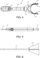
- FIG. 1 shows a delivery tool 100 with an implant 110 loaded on a guidewire 112 extending from a distal end of the delivery tool 100.
- FIG. 2 shows the distal end of the delivery tool 100 of FIG. 1 in greater detail.
- the implant 110 is loaded onto the guidewire 112 and abutted against a hypotube 114.
- the guidewire 112 extends beyond the distal end of the implant 110, however, any length of guidewire 112 may be considered for the inventive device described herein.
- an embodiment of an implant container 120 is shown coupled to the distal end of the delivery tool 100.
- the implant container 120 can releasably secure the implant 110 in a position such that a lumen of the implant is aligned with a delivery feature (e.g., hypotube 114 and/or guidewire 112) of the delivery tool 100.
- the implant container 120 in this embodiment is similar to a pen cap that is integrated onto the end of the delivery device 100.
- the implant container 120 provides several functions such as holding the implant 110 in the correct orientation and alignment during the loading procedure (e.g., loading the implant 110 onto the guidewire 112 extending from the distal end of the delivery tool 110).
- the implant container 120 may also protect the implant 110 during shipping, surgical preparation, and user interaction before the loading procedure begins.
- the implant container 120 of FIG. 3 is shown.
- the implant container 120 has an implant housing 130 that constrains the implant 110.
- the implant housing 130 is slightly smaller than the implant 110 in one or more dimensions to provide a friction fit.
- the implant housing 130 includes a chamber enclosed within a housing of the implant container 120 and in communication with a delivery passageway 132 that extends between the chamber and a proximal end of the container housing.
- the delivery passageway 132 is sized to allow the delivery feature of the implant device with the implant loaded thereon to travel along the delivery passageway 132 to exit the implant container 120 when the implant container 120 is decoupled from the delivery device 100.
- the implant container 120 may simply have a single feature that holds the implant 110, such as a loop or a spring clip, and the rest of the implant 110 may not be surrounded by material.
- the implant container 120 contains features that interface with the delivery device 100.
- the delivery passageway 132 assists assist with securing alignment between the delivery feature that includes an hypotube and the implant 110.
- the hypotube 114 and the delivery passageway 132 have a cylindrical cross-section and the delivery passageway 132 provides a sliding fit with the hypotube thereby axially constrain the implant container 120 to the delivery device 100 when the hypotube 114 extends along the delivery passageway 132.
- features may be added to the hypotube 114 that further allow for alignment and orientation of the implant container 120 relative to the delivery device 100. For example, cut features on the hypotube 114 or bosses extending out of the hypotube 114 may be used for alignment of the implant container 120 to the delivery device 100.
- the implant container 120 can interface with a handle component of the delivery device 100.
- the implant container 120 may have a feature such as a conical hole 122 that aligns with a conical feature 123 (see, for example, FIGs. 5 and 6 ) on the handle, which properly aligns and locates the implant container 120 relative to the delivery device 100. Any number of other features or components may be contemplated for interfacing the delivery tool 100 to the implant container 120.
- the implant container 120 can be securely held onto the distal end of the delivery device 100 like a pen cap.
- the implant container 120 may contain one or more coupling features that releasably couple the implant container 120 to the delivery device 100.
- the implant container 120 includes a pair of retention arms 125 that extend from a proximal end of the implant container 120 and are configured to engage with one or more coupling features 126 (e.g., groove, recess) on the delivery device 100 (see, for example, FIG. 1 ).
- the retention arms 125 may include cam surfaces 124 (see, for example, FIG. 11 ) that can be decoupled from the coupling feature 126 at the end of the loading procedure.
- Such decoupling can be caused by a feature associated with the delivery device 100 in order to eject the implant container 120 off the delivery device 100 after loading of the implant 110 onto the delivery feature of the delivery device 100.
- the implant container 120 may include a spring housing 129 that holds a spring that can be pressed against the front surface of the delivery tool 100 such that when the retention arms 125 are cammed out or decoupled from the delivery device 100, the implant container 120 is ejected off of the delivery device 100.
- other force mechanisms such as elastic deformation of the retention arms 125 may be used for ejecting the implant container 120.
- the implant container 120 may not include or require retention features for holding the implant container 120 against the delivery tool 100.
- the implant container 120 can include alignment features to allow the user to properly align the implant 110 and the delivery tool 100 before beginning the loading procedure.
- the implant container 120 may be manufactured from translucent or opaque plastics (i.e. polycarbonate, ABS, polypropylene, etc.), metals (i.e. stainless steel, titanium, etc.), or other equivalent materials.
- translucent plastics i.e. polycarbonate, ABS, polypropylene, etc.
- metals i.e. stainless steel, titanium, etc.
- the use of translucent plastics may allow the user to see the implant 110 in the implant housing 130, including during the loading procedure.
- one or more windows 128 may be included in the implant container 120 to allow the user to see the implant 110, such as during the loading procedure.
- the translucent plastic may be configured in such a way to magnify or enlarge an image of the implant during the loading procedure to make certain areas and features more visible.
- the implant container 120 consists of a single part comprised of injection molded plastic. In other embodiments, the implant container 120 may be comprised of any number of components secured together as an assembly. Furthermore, the components may be stationary relative to one another or move relative to one another such as telescoping components or features.
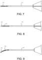
- FIGs. 5-9 a loading procedure with a delivery tool 100 is shown.
- a top view of a delivery tool 100 is shown with a loading button 135 at the proximal end and a hypotube 114 at the distal end.
- the delivery tool 100 can include a variety of handle components.
- FIG. 6 the distal end of the delivery tool 100 is shown in greater detail.
- the hypotube 114 may include a lumen that allows a guidewire to extend therethrough. As discussed in greater detail below, the guidewire can extend out of the hypotube 114 and retract into the hypotube 114.
- an implant 110 is shown in relation to the delivery tool 100.
- the lumen of the implant 110 is generally aligned with the axis of the hypotube 114 and when the guidewire 112 is extended it will enter the lumen of the implant 110 thereby loading the implant 110 onto the delivery tool 100.
- One of the functions of the container device 120 described herein is to align the implant 110 with the delivery tool 100, such as with a delivery feature (e.g., hypotube 114, guidewire 112) of the delivery tool 100, and reduce the amount of user input required to align and load the implant 110.
- a delivery feature e.g., hypotube 114, guidewire 112
- the guidewire 112 is extended through the lumen in the implant 110 and shown from a top view. As discussed above, any number of other holding mechanisms may be contemplated for securing the implant 110 to the delivery device 100.
- the delivery tool 100 and implant 110 are shown from a side view.
- the guidewire 112 may have a curve or bend that causes the implant 110 to curve or bend.
- the implant 110 may have a curve or bend that causes the guidewire 112 to curve or bend.
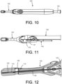
- the implant container 120 is shown coupled to the delivery tool 100 during the loading procedure.
- the proximal end of the implant container 120 can be releasably coupled to the distal end of the delivery tool 100, as shown in FIG. 10 .
- the implant container 120 is shown in greater detail with half of the handle of the delivery tool 100 removed thereby showing one of the retention arms 125 extending along the delivery device 100.
- the retention arms 125 are shown and can engage with a feature on the handle thereby securely mating the implant container 120 to the delivery tool 100, including during shipping and loading.
- An internal component shown is a piston 140.
- the piston 140 may be connected to other components such as the guidewire 112 such that by sliding the piston 140 distally, the guidewire 112 extends from the hypotube 114 and the implant 110 is loaded onto the guidewire 112. In such an embodiment, the piston 140 can be translated by pressing the loading button 145 on the proximal end of the delivery tool.
- the piston 140 may include piston cam arms 147 at the distal end that are configured to engage with the retention arms 125. As the piston cam arms 147 translate distally they can release the coupling between the retention arms 125 and the securing feature 126 thus allowing the implant container 120 to be ejected or removed from the delivery tool 100.
- the timing of the loading and the ejection of the implant container 120 may be timed such that ejection occurs after the loading of the implant 110 onto the guidewire 112. The user presses the loading button 135 and the implant 110 is loaded onto the guidewire 112 and the implant container 120 is actively or passively removed from the delivery tool 100.
- FIG. 12 a section view of the implant container 120 is shown.
- FIG. 13 a more detailed view of the implant 110 within the chamber or implant housing 130 of the implant container 120 is shown.
- the implant housing 130 as well coupling and alignment features associated with the housing of the implant container 120, holds the implant concentrically with the hypotube and the guidewire.
- the guidewire in FIG. 12 is shown retracted within the lumen of the hypotube.
- the implant 110 in FIG. 12 is constrained in the implant housing 130 such that the lumen of the implant 110 is coaxially aligned with the guidewire 112 and/or hypotube 114.
- the implant 110 may be under no stress in this configuration or may be held in place with any sufficient amount of force.
- the guidewire 112 is shown extended through the lumen of the implant 110.
- the guidewire 112 may extend beyond the end of the implant 110 or may only extend into a portion of the lumen.
- the implant 110 is shown loaded onto the guidewire 112 and the implant container 120 may now be decoupled from the delivery device 100.
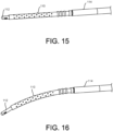
- the implant 110 loaded onto the guidewire 112 and delivery device 100 is shown decoupled from the implant container 120.
- the guidewire 112 is shown straight.
- the implant 110 and guidewire 112 are shown having a bend or curvature along a length.
- the guidewire 112 or the implant 110 or both may have a predetermined bend or curve that resumes its natural shape.
- features or mechanisms within the implant container 120 may be used to deform the implant 110 and/or guidewire 112 to induce a curve or other geometry.
- the implant container 120 may have a mechanism where the user can depress a component that flexes the implant 110 and guidewire 112 to a shape.
- the shape may be predefined or may be selected by the user depending on the force applied or distance moved. This may allow the user to control the shape of the implant 110 or the delivery tool 100 during the implantation procedure.
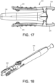
- FIG. 17 another embodiment of the implant container 220 is shown including another embodiment of a retention arms 225 that are connected to squeeze arms 226 that may be depressed by the user thereby disengaging the retention arms 225 from a complimenting coupling feature (e.g., groove) along the delivery device 200 to release the implant container 220.
- the implant may be loaded into the implant housing 230 for positioning and loading onto the delivery device 200.
- the squeeze arm implant container 220 is shown coupled to the delivery device 200.
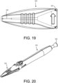
- FIG. 19 another embodiment of the implant container 320 is shown having another embodiment of a retention feature, which includes a retention pin 325 which sits into a groove or recess along the delivery tool 300 thereby securely coupling the implant container 320 to the delivery device 300.
- the groove can be configured like a screw thread that allows the retention pin 325 to thread onto and off of the delivery device 300.
- the implant 110 can be loaded into the implant housing 330 for positioning and loading the implant 110 onto the delivery device.
- the guidewire 112 can be advanced into the implant lumen by depressing the loader button 345 and then unthreading the implant container 320 from the delivery device 300 when preparing for surgery.
- the implant 110 may already be loaded onto the delivery device.
- the implant container (such as implant container 120, 220, and/or 320) may still serve several purposes.
- First the implant container 120, 220, 320 may protect the implant and prevent any damage from external forces.
- Second, the implant container 120, 220, 320 may hold the implant 110 in a desired shape or configuration.
- the implant container may hold the guidewire straight during the shipping of the device such that the implant is held straight and not subjected to unwanted forces during shipping or storage. In this case the implant container may be removed before the surgical procedure through any number of methods described herein.
- the guidewire 112 may be over-stroked through the implant 110 beyond its final intended position (while features of the container providing a distal hard stop for the implant), resulting in the guidewire 112 pulling the implant 110 proximally (via implant retention features on the guidewire) during its return-stroke with the guidewire hard stopping on the hypotube.
- the implant container may contain features that either permit or prevent re-capping the implant container onto a delivery device.
- the implant container can irreversibly split into two or more pieces after loading of the implant and removal of the container, thereby not allowing the user to re-cap the container.
- the implant container can contain a member that springs to close off the lumen after loading of the implant and removal of the implant container.
- the implant container may contain a springing feature that biases the implant proximally, so as to bias the implant towards the correct position during initial loading.
- various features such as speed bumps on the handle where the retention arm interfaces or a tether connecting the container to the handle body may be used to facilitate the profile of the container's ejection.
- the implant container design can also include various aerodynamic and friction elements to modify the profile of the container's ejection and minimize the ability to slide along flat surfaces such as tables or floors.
- the implant container may be locked on the delivery tool and cannot be removed with a normal user's hand-grip force until the user has loaded the implant.
- the container is not auto ejected, but the only action the user takes to allow the container to be removed is load the implant. Once the implant is loaded, the user can then proceed to remove the container. There can be a change in the container to signal to the user that it is now unlocked and can be removed, such as the appearance of a different color on the delivery tool handle (such as a green label appearing inside of a slot) or in the container itself.
- the implant may be held or contained in a specific environment within the implant container such as a fluid or gaseous environment. This may be beneficial for certain implant materials or configurations.
- the implant may be maintained in a saline solution and/or a therapeutic drug within the implant container.
- the chamber or implant housing can be fully are partially sealed to allow the saline and/or therapeutic drug to coat the implant, such as during storage.
- the implant container may be a sheath that holds the implant concentrically on the end of the delivery device and translates toward the delivery device as the implant is inserted in the eye.
- the implant container can be spring loaded proximally such that it contains the implant at the distal end but is able to move proximally and reveal the implant.
- the delivery device can be inserted into the eye and the implant container can be constrained by the corneal incision such that only the implant and the hypotube enter the eye.
- the implant container can contain multiple implants in a series of configurations.
- the implants can be contained in multiple cavities that are arranged such that the user can enter into a single cavity and load an implant onto the device.
- the cavities can be linked or unlinked such that they are contained separately and sterility of one implant is unaffected by the sterility of another implant.
- the user may use a single implant for one patient and then use a different implant and delivery tool for another patient without compromising sterility.
Landscapes
- Health & Medical Sciences (AREA)
- Life Sciences & Earth Sciences (AREA)
- Ophthalmology & Optometry (AREA)
- Veterinary Medicine (AREA)
- Engineering & Computer Science (AREA)
- Biomedical Technology (AREA)
- Heart & Thoracic Surgery (AREA)
- Animal Behavior & Ethology (AREA)
- General Health & Medical Sciences (AREA)
- Public Health (AREA)
- Vascular Medicine (AREA)
- Cardiology (AREA)
- Oral & Maxillofacial Surgery (AREA)
- Transplantation (AREA)
- Biophysics (AREA)
- Pulmonology (AREA)
- Anesthesiology (AREA)
- Hematology (AREA)
- Prostheses (AREA)
- Media Introduction/Drainage Providing Device (AREA)
- Dental Prosthetics (AREA)
Claims (15)
- Augenimplantatbehälter (120), umfassend:ein Behältergehäuse mit einem proximalen Ende, das zur Koppelung an eine Implantatzuführvorrichtung (100) ausgestaltet ist, undein Implantatgehäuse (130), das mit dem Behältergehäuse integriert und dazu ausgestaltet ist, ein Augenimplantat (110) zum Laden auf die Implantatzuführvorrichtung auszurichten und lösbar zu befestigen, wobei das Implantatgehäuse (130) eine Kammer aufweist, die so bemessen ist, dass sie einen Reibsitz mit dem Augenimplantat bereitstellt, wobei das Implantatgehäuse ferner einen Zuführdurchgang (132) aufweist, der mit der Kammer in Verbindung steht und sich zwischen der Kammer und dem proximalen Ende des Behältergehäuses erstreckt, wobei der Zuführdurchgang (132) einen kreisförmigen Querschnitt aufweist und dazu ausgestaltet ist, eine Gleitpassung mit einem Zuführmerkmal der Implantatzuführvorrichtung bereitzustellen, wobei das Zuführmerkmal ein Hypotube (114) aufweist.
- Implantatbehälter nach Anspruch 1, wobei, wenn ein Augenimplantat in der Kammer positioniert ist und der Implantatbehälter an ein Zuführwerkzeug gekoppelt ist, dessen Zuführmerkmal einen Führungsdraht (112) umfasst, so dass der Führungsdraht in dem Zuführdurchgang positioniert ist, ein Lumen des Augenimplantats auf den Führungsdraht des Zuführmerkmals der Implantatzuführvorrichtung ausgerichtet ist,optional wobei der Zuführdurchgang (132) einen Durchmesser aufweist, der es dem Führungsdraht mit dem geladenen Augenimplantat gestattet, daran entlang zu translatieren und aus dem Gehäuse auszutreten, wenn das Behältergehäuse von der Implantatzuführvorrichtung entkoppelt ist,und ferner optional wobei das Hypotube (114) ein inneres Lumen aufweist, das so ausgestaltet ist, dass der Führungsdraht daran entlang translatieren kann.
- Implantatbehälter nach Anspruch 1 oder Anspruch 2, ferner umfassend ein Koppelmerkmal an dem proximalen Ende des Gehäuses, das dazu ausgestaltet ist, lösbar an die Implantatzuführvorrichtung zu koppeln und/oder das Zuführmerkmal der Implantatzuführvorrichtung auf den Implantatpositionierer zum Laden des Augenimplantats auf das Zuführmerkmal auszurichten.
- Implantatbehälter nach Anspruch 3, wobei das Koppelmerkmal den Implantatbehälter bezüglich der Implantatzuführvorrichtung axial festlegt.
- Implantatbehälter nach Anspruch 3, wobei das Koppelmerkmal mindestens einen Haltearm (125, 225) umfasst, der sich von dem proximalen Ende des Gehäuses erstreckt und eine Nockenfläche aufweist, die zum lösbaren Koppeln an ein Befestigungsmerkmal (126) der Implantatzuführvorrichtung ausgestaltet ist.
- Implantatbehälter nach Anspruch 5, wobei die Implantatzuführvorrichtung ein Lösemerkmal aufweist, das den mindestens einen Haltearm von dem Befestigungsmerkmal entkoppelt, nachdem das Augenimplantat auf das Zuführmerkmal geladen worden ist.
- Implantatbehälter nach Anspruch 5, wobei das Behältergehäuse einen Quetscharm (226) aufweist, der an den mindestens einen Haltearm wirkgekoppelt ist, so dass der mindestens eine Haltearm von der Implantatzuführvorrichtung entkoppelt wird, wenn der Quetscharm niedergedrückt wird, wodurch das Gehäuse von der Implantatzuführvorrichtung entkoppelt wird.
- Implantatbehälter nach Anspruch 3, wobei das Koppelmerkmal Folgendes aufweist:entweder eine ausgesparte Kegelform an dem proximalen Ende des Behältergehäuses, wobei die ausgesparte Kegelform eine Gleitpassung mit einem distalen Ende der Implantatzuführvorrichtung bereitstellt,oder einen Stift (325), der zur Ineingriffnahme eines Gewindemerkmals der Implantatzuführvorrichtung ausgestaltet ist, wodurch das Behältergehäuse an die Implantatzuführvorrichtung gekoppelt wird.
- Implantatbehälter nach einem der vorhergehenden Ansprüche, wobei die Kammer ein Fluid aufweist, das eine Kochsalzlösung und/oder ein therapeutisches Arzneimittel umfasst.
- Implantatbehälter nach einem der vorhergehenden Ansprüche, wobei ein Teil (128) des Behältergehäuses aus einem durchscheinenden Material hergestellt ist, wodurch ein Benutzer das Augenimplantat in der Kammer einsehen kann,
optional wobei das durchscheinende Material eine Vergrößerungseigenschaft aufweist, durch die ein Bild des Augenimplantats in der Kammer vergrößert wird. - Verfahren zum Laden eines Augenimplantats in einen Implantatbehälter nach einem der vorhergehenden Ansprüche, umfassend:
Laden eines Augenimplantats (110) in ein Implantatgehäuse (130) eines Implantatbehälters (120), wobei der Implantatbehälter das Implantatgehäuse (130) umfasst, das dazu ausgestaltet ist, zum Laden des Augenimplantats auf die Implantatzuführvorrichtung an eine Implantatzuführvorrichtung (100) gekoppelt zu werden, wobei das Implantatgehäuse dazu ausgestaltet ist, das Augenimplantat auf ein Zuführmerkmal der Implantatzuführvorrichtung auszurichten, wenn das Behältergehäuse an die Implantatzuführvorrichtung gekoppelt ist, wobei das Implantatgehäuse (130) eine Kammer aufweist, die so bemessen ist, dass sie eine Reibpassung mit einem Augenimplantat bereitstellt, wobei das Implantatgehäuse ferner einen Zuführdurchgang (132) aufweist, der mit der Kammer in Verbindung steht und sich zwischen der Kammer und dem proximalen Ende des Behältergehäuses erstreckt, wobei der Zuführdurchgang (132) einen kreisförmigen Querschnitt aufweist und zur Bereitstellung einer Gleitpassung mit einem Zuführmerkmal der Implantatzuführvorrichtung ausgestaltet ist, wobei das Zuführmerkmal ein Hypotube (114) aufweist. - Verfahren nach Anspruch 11, ferner umfassend:Koppeln des Gehäuses des Implantatbehälters an die Implantatzuführvorrichtung, wodurch das Zuführmerkmal der Implantatzuführvorrichtung auf das Augenimplantat ausgerichtet wird,Laden des Augenimplantats auf das Zuführmerkmal undEntkoppeln des Behältergehäuses von der Implantatzuführvorrichtung, wodurch das auf das Zuführmerkmal geladene Augenimplantat aus dem Implantatbehälter entfernt wird.
- Verfahren nach Anspruch 12, wobei das Laden des Augenimplantats auf die Implantatzuführvorrichtung Längstranslatieren eines Führungsdrahts (112) in ein Lumen des Augenimplantats umfasst.
- Verfahren nach Anspruch 12 oder Anspruch 13, ferner umfassend Aktivieren eines Entkoppelmerkmals, das dem Implantatbehälter und/oder der Implantatzuführvorrichtung zugeordnet ist, um das Entkoppeln des Behältergehäuses von der Implantatzuführvorrichtung zu veranlassen.
- System, umfassend:eine Implantatzuführvorrichtung (100),ein Augenimplantat (110) undden Augenimplantatbehälter (120) nach einem der Ansprüche 1 bis 10.
Applications Claiming Priority (2)
| Application Number | Priority Date | Filing Date | Title |
|---|---|---|---|
| US201562221918P | 2015-09-22 | 2015-09-22 | |
| PCT/IB2016/001422 WO2017051247A1 (en) | 2015-09-22 | 2016-09-16 | Ocular implant container |
Publications (2)
| Publication Number | Publication Date |
|---|---|
| EP3370644A1 EP3370644A1 (de) | 2018-09-12 |
| EP3370644B1 true EP3370644B1 (de) | 2025-04-16 |
Family
ID=57223727
Family Applications (1)
| Application Number | Title | Priority Date | Filing Date |
|---|---|---|---|
| EP16790424.2A Active EP3370644B1 (de) | 2015-09-22 | 2016-09-16 | Augenimplantatbehälter |
Country Status (6)
| Country | Link |
|---|---|
| US (1) | US10322029B2 (de) |
| EP (1) | EP3370644B1 (de) |
| CN (1) | CN108024854B (de) |
| CA (1) | CA3005151C (de) |
| ES (1) | ES3031461T3 (de) |
| WO (1) | WO2017051247A1 (de) |
Families Citing this family (6)
| Publication number | Priority date | Publication date | Assignee | Title |
|---|---|---|---|---|
| PT2526910E (pt) | 2006-01-17 | 2015-11-18 | Transcend Medical Inc | Dispositivo para tratamento de glaucoma |
| EP2395951B1 (de) | 2009-01-28 | 2020-07-29 | Alcon Inc. | Augenimplantat mit steifheitseigenschaften |
| JP7325451B2 (ja) | 2018-06-05 | 2023-08-14 | カール・ツァイス・メディテック・キャタラクト・テクノロジー・インコーポレイテッド | 眼科顕微手術ツール、システム、および使用方法 |
| AU2020216205A1 (en) | 2019-02-01 | 2021-08-26 | Carl Zeiss Meditec Cataract Technology Inc. | Ophthalmic cutting instruments having integrated aspiration pump |
| WO2020236593A1 (en) | 2019-05-17 | 2020-11-26 | Carl Zeiss Meditec Cataract Technology Inc. | Ophthalmic cutting instruments having integrated aspiration pump |
| KR20220032046A (ko) | 2019-06-07 | 2022-03-15 | 칼 짜이스 메디텍 캐터랙트 테크놀로지 인크. | 안과 절단 도구용 다중 스테이지 트리거 |
Family Cites Families (38)
| Publication number | Priority date | Publication date | Assignee | Title |
|---|---|---|---|---|
| US5180362A (en) | 1990-04-03 | 1993-01-19 | Worst J G F | Gonio seton |
| NL1004162C2 (nl) * | 1996-10-01 | 1998-04-02 | Cordis Europ | Ballonkatheter voor stentplaatsing. |
| AU5280600A (en) * | 1999-05-20 | 2000-12-12 | Scimed Life Systems, Inc. | Stent delivery system with nested stabilizer and method of loading and using same |
| US6699274B2 (en) * | 2001-01-22 | 2004-03-02 | Scimed Life Systems, Inc. | Stent delivery system and method of manufacturing same |
| US20040147870A1 (en) * | 2002-04-08 | 2004-07-29 | Burns Thomas W. | Glaucoma treatment kit |
| US20040016787A1 (en) * | 2002-07-16 | 2004-01-29 | Ioime Joseph L. | Golfing accessory |
| US20040225250A1 (en) | 2003-05-05 | 2004-11-11 | Michael Yablonski | Internal shunt and method for treating glaucoma |
| US7291125B2 (en) | 2003-11-14 | 2007-11-06 | Transcend Medical, Inc. | Ocular pressure regulation |
| US20060142780A1 (en) * | 2004-12-29 | 2006-06-29 | Joel Pynson | Preloaded IOL injector and method |
| US9084662B2 (en) | 2006-01-17 | 2015-07-21 | Transcend Medical, Inc. | Drug delivery treatment device |
| PT2526910E (pt) | 2006-01-17 | 2015-11-18 | Transcend Medical Inc | Dispositivo para tratamento de glaucoma |
| WO2007087641A2 (en) * | 2006-01-26 | 2007-08-02 | Advanced Medical Optics, Inc. | Intraocular lens insertion apparatus and lens case |
| JP5328788B2 (ja) | 2007-07-17 | 2013-10-30 | トランセンド・メディカル・インコーポレイテッド | ヒドロゲルの拡張能力を備えた眼内植込み体 |
| CA2705239C (en) | 2007-11-08 | 2018-09-25 | Alimera Sciences, Inc. | Ocular implantation device |
| US8617139B2 (en) | 2008-06-25 | 2013-12-31 | Transcend Medical, Inc. | Ocular implant with shape change capabilities |
| WO2009158517A2 (en) | 2008-06-26 | 2009-12-30 | Transcend Medical, Inc. | Digital imaging system for eye procedures |
| TWI455734B (zh) | 2008-11-20 | 2014-10-11 | Alcon Res Ltd | 帶有具內部塗層之匣的人工水晶體輸送裝置 |
| EP2395951B1 (de) | 2009-01-28 | 2020-07-29 | Alcon Inc. | Augenimplantat mit steifheitseigenschaften |
| US8337393B2 (en) | 2009-04-03 | 2012-12-25 | Transcend Medical, Inc. | Ocular implant delivery systems and methods |
| US8535333B2 (en) | 2009-07-29 | 2013-09-17 | Transcend Medical, Inc. | Ocular implant applier and methods of use |
| US20110118835A1 (en) | 2009-08-13 | 2011-05-19 | Matthew Silvestrini | Branched ocular implant |
| US20110105990A1 (en) | 2009-11-04 | 2011-05-05 | Silvestrini Thomas A | Zonal drug delivery device and method |
| US8529492B2 (en) | 2009-12-23 | 2013-09-10 | Trascend Medical, Inc. | Drug delivery devices and methods |
| US8758433B2 (en) | 2010-04-23 | 2014-06-24 | Abbott Medical Optics Inc. | Insertion mode phacoemulsification employing powered IOL delivery |
| US8444589B2 (en) | 2010-06-09 | 2013-05-21 | Transcend Medical, Inc. | Ocular implant with fluid outflow pathways having microporous membranes |
| US8545430B2 (en) | 2010-06-09 | 2013-10-01 | Transcend Medical, Inc. | Expandable ocular devices |
| EP2768380B1 (de) | 2011-10-21 | 2018-08-08 | Novartis Ag | Goniolinsensystem mit stabilisierungsmechanismus |
| JP6339065B2 (ja) * | 2012-04-19 | 2018-06-06 | ノバルティス アーゲー | 眼内インプラントのためのデリバリシステム |
| US10085633B2 (en) | 2012-04-19 | 2018-10-02 | Novartis Ag | Direct visualization system for glaucoma treatment |
| US9241832B2 (en) | 2012-04-24 | 2016-01-26 | Transcend Medical, Inc. | Delivery system for ocular implant |
| US9999499B2 (en) | 2012-09-04 | 2018-06-19 | Carl Zeiss Meditec Production, LLC | Preloaded intraocular lens (IOL) system and method |
| US9480598B2 (en) | 2012-09-17 | 2016-11-01 | Novartis Ag | Expanding ocular implant devices and methods |
| US9763829B2 (en) | 2012-11-14 | 2017-09-19 | Novartis Ag | Flow promoting ocular implant |
| US10154924B2 (en) | 2013-01-28 | 2018-12-18 | Novartis Ag | Schlemm's canal devices and method for improving fluid flow |
| US9987163B2 (en) * | 2013-04-16 | 2018-06-05 | Novartis Ag | Device for dispensing intraocular substances |
| US20140323995A1 (en) | 2013-04-24 | 2014-10-30 | Transcend Medical, Inc. | Targeted Drug Delivery Devices and Methods |
| WO2014190029A1 (en) | 2013-05-21 | 2014-11-27 | Transcend Medical, Inc. | Flow promoting ocular implant device and methods |
| AU2015223010A1 (en) * | 2014-02-26 | 2016-09-15 | Allergan, Inc. | Intraocular implant delivery apparatus and methods of use thereof |
-
2016
- 2016-09-16 EP EP16790424.2A patent/EP3370644B1/de active Active
- 2016-09-16 CN CN201680055072.3A patent/CN108024854B/zh active Active
- 2016-09-16 CA CA3005151A patent/CA3005151C/en active Active
- 2016-09-16 ES ES16790424T patent/ES3031461T3/es active Active
- 2016-09-16 WO PCT/IB2016/001422 patent/WO2017051247A1/en not_active Ceased
- 2016-09-16 US US15/268,305 patent/US10322029B2/en active Active
Also Published As
| Publication number | Publication date |
|---|---|
| CN108024854A (zh) | 2018-05-11 |
| CA3005151C (en) | 2024-05-28 |
| WO2017051247A1 (en) | 2017-03-30 |
| US20170079839A1 (en) | 2017-03-23 |
| EP3370644A1 (de) | 2018-09-12 |
| ES3031461T3 (en) | 2025-07-09 |
| US10322029B2 (en) | 2019-06-18 |
| CA3005151A1 (en) | 2017-03-30 |
| CN108024854B (zh) | 2021-03-19 |
Similar Documents
| Publication | Publication Date | Title |
|---|---|---|
| EP3370644B1 (de) | Augenimplantatbehälter | |
| US8470030B2 (en) | Device for loading an intraocular lens into an injection cartridge | |
| CN103179918B (zh) | 用于插入装置的保护帽及其他插入装置特征 | |
| US10010409B2 (en) | Intraocular lens injector, method for folding an intraocular lens and intraocular lens injector system | |
| US11980740B2 (en) | Stabilization and guide apparatus for access to an implanted access port and related methods | |
| US4699140A (en) | Instrument for inserting an intraocular lens | |
| EP2579814B1 (de) | Einsatzsystem für ein augenimplantat | |
| JP6029659B2 (ja) | 眼内レンズを移植するインジェクター | |
| US8961531B2 (en) | Intraocular lens transfer case | |
| US20060085013A1 (en) | Intraocular lens inserter | |
| US10105258B2 (en) | Device for receiving an intraocular lens, and method for folding an intraocular lens | |
| EP1967161A1 (de) | Linseneinführsystem | |
| EP2567674B1 (de) | Modulare Injektor für Intraokularlinsen | |
| CN108430388A (zh) | 人工晶状体递送装置及使用方法 | |
| EP3787559B1 (de) | Intraokularlinseninjektor | |
| EP1613247A2 (de) | Weiterentwicklung eines systems zur implantation von intraokularlinsen | |
| EP2417996A1 (de) | Medizinische Einsatzeinführungsvorrichtung | |
| JP2009028223A (ja) | 眼内レンズ挿入器具 | |
| JP7136995B2 (ja) | 眼内レンズインジェクタ | |
| JP7664273B2 (ja) | インプラント送出のためのシャフト組立体を保持及び提供するためのパッケージ | |
| EP3372197A1 (de) | Intraokularlinseninjektor und verfahren zum betreiben eines intraokularlinseninjektors | |
| KR20230107549A (ko) | 수술용 임플란트의 유압식 전달 | |
| RU2783499C2 (ru) | Шприц, рукоятка шприца, корпус |
Legal Events
| Date | Code | Title | Description |
|---|---|---|---|
| STAA | Information on the status of an ep patent application or granted ep patent |
Free format text: STATUS: UNKNOWN |
|
| STAA | Information on the status of an ep patent application or granted ep patent |
Free format text: STATUS: THE INTERNATIONAL PUBLICATION HAS BEEN MADE |
|
| PUAI | Public reference made under article 153(3) epc to a published international application that has entered the european phase |
Free format text: ORIGINAL CODE: 0009012 |
|
| STAA | Information on the status of an ep patent application or granted ep patent |
Free format text: STATUS: REQUEST FOR EXAMINATION WAS MADE |
|
| 17P | Request for examination filed |
Effective date: 20180615 |
|
| AK | Designated contracting states |
Kind code of ref document: A1 Designated state(s): AL AT BE BG CH CY CZ DE DK EE ES FI FR GB GR HR HU IE IS IT LI LT LU LV MC MK MT NL NO PL PT RO RS SE SI SK SM TR |
|
| AX | Request for extension of the european patent |
Extension state: BA ME |
|
| DAV | Request for validation of the european patent (deleted) | ||
| DAX | Request for extension of the european patent (deleted) | ||
| RAP1 | Party data changed (applicant data changed or rights of an application transferred) |
Owner name: ALCON INC. |
|
| STAA | Information on the status of an ep patent application or granted ep patent |
Free format text: STATUS: EXAMINATION IS IN PROGRESS |
|
| 17Q | First examination report despatched |
Effective date: 20210428 |
|
| P01 | Opt-out of the competence of the unified patent court (upc) registered |
Effective date: 20230507 |
|
| GRAP | Despatch of communication of intention to grant a patent |
Free format text: ORIGINAL CODE: EPIDOSNIGR1 |
|
| STAA | Information on the status of an ep patent application or granted ep patent |
Free format text: STATUS: GRANT OF PATENT IS INTENDED |
|
| INTG | Intention to grant announced |
Effective date: 20241114 |
|
| GRAS | Grant fee paid |
Free format text: ORIGINAL CODE: EPIDOSNIGR3 |
|
| GRAA | (expected) grant |
Free format text: ORIGINAL CODE: 0009210 |
|
| STAA | Information on the status of an ep patent application or granted ep patent |
Free format text: STATUS: THE PATENT HAS BEEN GRANTED |
|
| AK | Designated contracting states |
Kind code of ref document: B1 Designated state(s): AL AT BE BG CH CY CZ DE DK EE ES FI FR GB GR HR HU IE IS IT LI LT LU LV MC MK MT NL NO PL PT RO RS SE SI SK SM TR |
|
| REG | Reference to a national code |
Ref country code: GB Ref legal event code: FG4D |
|
| REG | Reference to a national code |
Ref country code: CH Ref legal event code: EP |
|
| REG | Reference to a national code |
Ref country code: IE Ref legal event code: FG4D |
|
| REG | Reference to a national code |
Ref country code: DE Ref legal event code: R096 Ref document number: 602016091925 Country of ref document: DE |
|
| REG | Reference to a national code |
Ref country code: ES Ref legal event code: FG2A Ref document number: 3031461 Country of ref document: ES Kind code of ref document: T3 Effective date: 20250709 |
|
| REG | Reference to a national code |
Ref country code: NL Ref legal event code: MP Effective date: 20250416 |
|
| PG25 | Lapsed in a contracting state [announced via postgrant information from national office to epo] |
Ref country code: NL Free format text: LAPSE BECAUSE OF FAILURE TO SUBMIT A TRANSLATION OF THE DESCRIPTION OR TO PAY THE FEE WITHIN THE PRESCRIBED TIME-LIMIT Effective date: 20250416 |
|
| REG | Reference to a national code |
Ref country code: AT Ref legal event code: MK05 Ref document number: 1785032 Country of ref document: AT Kind code of ref document: T Effective date: 20250416 |
|
| PG25 | Lapsed in a contracting state [announced via postgrant information from national office to epo] |
Ref country code: FI Free format text: LAPSE BECAUSE OF FAILURE TO SUBMIT A TRANSLATION OF THE DESCRIPTION OR TO PAY THE FEE WITHIN THE PRESCRIBED TIME-LIMIT Effective date: 20250416 Ref country code: PT Free format text: LAPSE BECAUSE OF FAILURE TO SUBMIT A TRANSLATION OF THE DESCRIPTION OR TO PAY THE FEE WITHIN THE PRESCRIBED TIME-LIMIT Effective date: 20250818 |
|
| PGFP | Annual fee paid to national office [announced via postgrant information from national office to epo] |
Ref country code: DE Payment date: 20250819 Year of fee payment: 10 |
|
| REG | Reference to a national code |
Ref country code: LT Ref legal event code: MG9D |
|
| PG25 | Lapsed in a contracting state [announced via postgrant information from national office to epo] |
Ref country code: GR Free format text: LAPSE BECAUSE OF FAILURE TO SUBMIT A TRANSLATION OF THE DESCRIPTION OR TO PAY THE FEE WITHIN THE PRESCRIBED TIME-LIMIT Effective date: 20250717 Ref country code: NO Free format text: LAPSE BECAUSE OF FAILURE TO SUBMIT A TRANSLATION OF THE DESCRIPTION OR TO PAY THE FEE WITHIN THE PRESCRIBED TIME-LIMIT Effective date: 20250716 |
|
| PG25 | Lapsed in a contracting state [announced via postgrant information from national office to epo] |
Ref country code: PL Free format text: LAPSE BECAUSE OF FAILURE TO SUBMIT A TRANSLATION OF THE DESCRIPTION OR TO PAY THE FEE WITHIN THE PRESCRIBED TIME-LIMIT Effective date: 20250416 |
|
| PGFP | Annual fee paid to national office [announced via postgrant information from national office to epo] |
Ref country code: IT Payment date: 20250827 Year of fee payment: 10 |
|
| PG25 | Lapsed in a contracting state [announced via postgrant information from national office to epo] |
Ref country code: BG Free format text: LAPSE BECAUSE OF FAILURE TO SUBMIT A TRANSLATION OF THE DESCRIPTION OR TO PAY THE FEE WITHIN THE PRESCRIBED TIME-LIMIT Effective date: 20250416 |
|
| PGFP | Annual fee paid to national office [announced via postgrant information from national office to epo] |
Ref country code: GB Payment date: 20250821 Year of fee payment: 10 |
|
| PG25 | Lapsed in a contracting state [announced via postgrant information from national office to epo] |
Ref country code: HR Free format text: LAPSE BECAUSE OF FAILURE TO SUBMIT A TRANSLATION OF THE DESCRIPTION OR TO PAY THE FEE WITHIN THE PRESCRIBED TIME-LIMIT Effective date: 20250416 |
|
| PG25 | Lapsed in a contracting state [announced via postgrant information from national office to epo] |
Ref country code: AT Free format text: LAPSE BECAUSE OF FAILURE TO SUBMIT A TRANSLATION OF THE DESCRIPTION OR TO PAY THE FEE WITHIN THE PRESCRIBED TIME-LIMIT Effective date: 20250416 |
|
| PGFP | Annual fee paid to national office [announced via postgrant information from national office to epo] |
Ref country code: FR Payment date: 20250821 Year of fee payment: 10 |
|
| PG25 | Lapsed in a contracting state [announced via postgrant information from national office to epo] |
Ref country code: RS Free format text: LAPSE BECAUSE OF FAILURE TO SUBMIT A TRANSLATION OF THE DESCRIPTION OR TO PAY THE FEE WITHIN THE PRESCRIBED TIME-LIMIT Effective date: 20250716 |
|
| PG25 | Lapsed in a contracting state [announced via postgrant information from national office to epo] |
Ref country code: IS Free format text: LAPSE BECAUSE OF FAILURE TO SUBMIT A TRANSLATION OF THE DESCRIPTION OR TO PAY THE FEE WITHIN THE PRESCRIBED TIME-LIMIT Effective date: 20250816 |
|
| PG25 | Lapsed in a contracting state [announced via postgrant information from national office to epo] |
Ref country code: LV Free format text: LAPSE BECAUSE OF FAILURE TO SUBMIT A TRANSLATION OF THE DESCRIPTION OR TO PAY THE FEE WITHIN THE PRESCRIBED TIME-LIMIT Effective date: 20250416 |
|
| PG25 | Lapsed in a contracting state [announced via postgrant information from national office to epo] |
Ref country code: SM Free format text: LAPSE BECAUSE OF FAILURE TO SUBMIT A TRANSLATION OF THE DESCRIPTION OR TO PAY THE FEE WITHIN THE PRESCRIBED TIME-LIMIT Effective date: 20250416 Ref country code: DK Free format text: LAPSE BECAUSE OF FAILURE TO SUBMIT A TRANSLATION OF THE DESCRIPTION OR TO PAY THE FEE WITHIN THE PRESCRIBED TIME-LIMIT Effective date: 20250416 |
|
| PG25 | Lapsed in a contracting state [announced via postgrant information from national office to epo] |
Ref country code: CZ Free format text: LAPSE BECAUSE OF FAILURE TO SUBMIT A TRANSLATION OF THE DESCRIPTION OR TO PAY THE FEE WITHIN THE PRESCRIBED TIME-LIMIT Effective date: 20250416 |
|
| PG25 | Lapsed in a contracting state [announced via postgrant information from national office to epo] |
Ref country code: EE Free format text: LAPSE BECAUSE OF FAILURE TO SUBMIT A TRANSLATION OF THE DESCRIPTION OR TO PAY THE FEE WITHIN THE PRESCRIBED TIME-LIMIT Effective date: 20250416 |
|
| PG25 | Lapsed in a contracting state [announced via postgrant information from national office to epo] |
Ref country code: SK Free format text: LAPSE BECAUSE OF FAILURE TO SUBMIT A TRANSLATION OF THE DESCRIPTION OR TO PAY THE FEE WITHIN THE PRESCRIBED TIME-LIMIT Effective date: 20250416 Ref country code: RO Free format text: LAPSE BECAUSE OF FAILURE TO SUBMIT A TRANSLATION OF THE DESCRIPTION OR TO PAY THE FEE WITHIN THE PRESCRIBED TIME-LIMIT Effective date: 20250416 |
|
| PGFP | Annual fee paid to national office [announced via postgrant information from national office to epo] |
Ref country code: ES Payment date: 20251016 Year of fee payment: 10 |