EP3370563B1 - Système d'emballage de transport de produits - Google Patents
Système d'emballage de transport de produits Download PDFInfo
- Publication number
- EP3370563B1 EP3370563B1 EP16852884.2A EP16852884A EP3370563B1 EP 3370563 B1 EP3370563 B1 EP 3370563B1 EP 16852884 A EP16852884 A EP 16852884A EP 3370563 B1 EP3370563 B1 EP 3370563B1
- Authority
- EP
- European Patent Office
- Prior art keywords
- bag
- kraft paper
- rigid container
- container
- storage space
- Prior art date
- Legal status (The legal status is an assumption and is not a legal conclusion. Google has not performed a legal analysis and makes no representation as to the accuracy of the status listed.)
- Active
Links
- 238000004806 packaging method and process Methods 0.000 title 1
- 239000002655 kraft paper Substances 0.000 claims description 370
- 238000003860 storage Methods 0.000 claims description 357
- 239000003570 air Substances 0.000 claims description 317
- XLYOFNOQVPJJNP-UHFFFAOYSA-N water Substances O XLYOFNOQVPJJNP-UHFFFAOYSA-N 0.000 claims description 248
- 239000000463 material Substances 0.000 claims description 243
- 238000000034 method Methods 0.000 claims description 175
- 239000012528 membrane Substances 0.000 claims description 100
- 239000012298 atmosphere Substances 0.000 claims description 49
- 238000011068 loading method Methods 0.000 claims description 48
- 238000012856 packing Methods 0.000 claims description 46
- 238000009833 condensation Methods 0.000 claims description 42
- 230000005494 condensation Effects 0.000 claims description 42
- 230000002745 absorbent Effects 0.000 claims description 39
- 239000002250 absorbent Substances 0.000 claims description 39
- 238000012546 transfer Methods 0.000 claims description 35
- 239000012080 ambient air Substances 0.000 claims description 29
- 230000001419 dependent effect Effects 0.000 claims description 24
- 238000007789 sealing Methods 0.000 claims description 20
- 239000012782 phase change material Substances 0.000 claims description 17
- 239000007787 solid Substances 0.000 claims description 13
- 230000035699 permeability Effects 0.000 claims description 11
- 230000000063 preceeding effect Effects 0.000 claims 9
- 239000010410 layer Substances 0.000 description 326
- 230000002787 reinforcement Effects 0.000 description 137
- 239000000123 paper Substances 0.000 description 129
- CURLTUGMZLYLDI-UHFFFAOYSA-N Carbon dioxide Chemical compound O=C=O CURLTUGMZLYLDI-UHFFFAOYSA-N 0.000 description 83
- 239000012212 insulator Substances 0.000 description 48
- 238000012360 testing method Methods 0.000 description 33
- 238000001816 cooling Methods 0.000 description 32
- 229910002092 carbon dioxide Inorganic materials 0.000 description 31
- 239000007788 liquid Substances 0.000 description 30
- 239000001569 carbon dioxide Substances 0.000 description 29
- 239000007789 gas Substances 0.000 description 26
- 238000004519 manufacturing process Methods 0.000 description 26
- 235000011089 carbon dioxide Nutrition 0.000 description 23
- 238000011049 filling Methods 0.000 description 22
- 230000008014 freezing Effects 0.000 description 22
- 238000007710 freezing Methods 0.000 description 22
- 239000004698 Polyethylene Substances 0.000 description 20
- 239000003981 vehicle Substances 0.000 description 20
- 229920003023 plastic Polymers 0.000 description 19
- 239000004033 plastic Substances 0.000 description 19
- 235000013305 food Nutrition 0.000 description 18
- 239000013505 freshwater Substances 0.000 description 18
- 238000004026 adhesive bonding Methods 0.000 description 17
- 230000008901 benefit Effects 0.000 description 17
- IUVCFHHAEHNCFT-INIZCTEOSA-N 2-[(1s)-1-[4-amino-3-(3-fluoro-4-propan-2-yloxyphenyl)pyrazolo[3,4-d]pyrimidin-1-yl]ethyl]-6-fluoro-3-(3-fluorophenyl)chromen-4-one Chemical compound C1=C(F)C(OC(C)C)=CC=C1C(C1=C(N)N=CN=C11)=NN1[C@@H](C)C1=C(C=2C=C(F)C=CC=2)C(=O)C2=CC(F)=CC=C2O1 IUVCFHHAEHNCFT-INIZCTEOSA-N 0.000 description 16
- 230000000694 effects Effects 0.000 description 15
- 230000008569 process Effects 0.000 description 15
- 235000013611 frozen food Nutrition 0.000 description 14
- 238000004891 communication Methods 0.000 description 13
- 238000005520 cutting process Methods 0.000 description 13
- 238000010438 heat treatment Methods 0.000 description 13
- 229920000642 polymer Polymers 0.000 description 11
- 239000003292 glue Substances 0.000 description 10
- -1 polyethylene Polymers 0.000 description 10
- 229920001169 thermoplastic Polymers 0.000 description 10
- 239000004416 thermosoftening plastic Substances 0.000 description 10
- 238000010792 warming Methods 0.000 description 10
- 229920000704 biodegradable plastic Polymers 0.000 description 9
- 230000008859 change Effects 0.000 description 9
- 238000010586 diagram Methods 0.000 description 9
- 238000005259 measurement Methods 0.000 description 9
- 230000002829 reductive effect Effects 0.000 description 9
- 239000004753 textile Substances 0.000 description 9
- 235000013372 meat Nutrition 0.000 description 8
- 229920005597 polymer membrane Polymers 0.000 description 8
- 230000002123 temporal effect Effects 0.000 description 8
- 238000003466 welding Methods 0.000 description 8
- 230000003247 decreasing effect Effects 0.000 description 7
- 229920001971 elastomer Polymers 0.000 description 7
- 230000014759 maintenance of location Effects 0.000 description 7
- 239000002861 polymer material Substances 0.000 description 7
- 229920006395 saturated elastomer Polymers 0.000 description 7
- 230000009471 action Effects 0.000 description 6
- 230000001413 cellular effect Effects 0.000 description 6
- 239000002826 coolant Substances 0.000 description 6
- 230000007423 decrease Effects 0.000 description 6
- 238000009413 insulation Methods 0.000 description 6
- 239000008188 pellet Substances 0.000 description 6
- 239000012071 phase Substances 0.000 description 6
- 229920000573 polyethylene Polymers 0.000 description 6
- 230000015572 biosynthetic process Effects 0.000 description 5
- 235000013330 chicken meat Nutrition 0.000 description 5
- 230000000295 complement effect Effects 0.000 description 5
- 230000006870 function Effects 0.000 description 5
- 230000013011 mating Effects 0.000 description 5
- 235000013336 milk Nutrition 0.000 description 5
- 239000008267 milk Substances 0.000 description 5
- 210000004080 milk Anatomy 0.000 description 5
- 239000000203 mixture Substances 0.000 description 5
- 238000000859 sublimation Methods 0.000 description 5
- 230000008022 sublimation Effects 0.000 description 5
- 239000000853 adhesive Substances 0.000 description 4
- 230000001070 adhesive effect Effects 0.000 description 4
- 239000002390 adhesive tape Substances 0.000 description 4
- 230000004888 barrier function Effects 0.000 description 4
- 239000011111 cardboard Substances 0.000 description 4
- 235000013365 dairy product Nutrition 0.000 description 4
- 238000009826 distribution Methods 0.000 description 4
- 239000003921 oil Substances 0.000 description 4
- 229920001084 poly(chloroprene) Polymers 0.000 description 4
- 241000287828 Gallus gallus Species 0.000 description 3
- 238000010521 absorption reaction Methods 0.000 description 3
- 238000013461 design Methods 0.000 description 3
- 230000005484 gravity Effects 0.000 description 3
- 229920001684 low density polyethylene Polymers 0.000 description 3
- 239000004702 low-density polyethylene Substances 0.000 description 3
- 239000004626 polylactic acid Substances 0.000 description 3
- 238000003825 pressing Methods 0.000 description 3
- 238000009877 rendering Methods 0.000 description 3
- 230000004044 response Effects 0.000 description 3
- 238000010257 thawing Methods 0.000 description 3
- 235000001674 Agaricus brunnescens Nutrition 0.000 description 2
- 239000004743 Polypropylene Substances 0.000 description 2
- 239000004372 Polyvinyl alcohol Substances 0.000 description 2
- 229910052799 carbon Inorganic materials 0.000 description 2
- 230000008021 deposition Effects 0.000 description 2
- 239000006185 dispersion Substances 0.000 description 2
- 235000013399 edible fruits Nutrition 0.000 description 2
- 230000005611 electricity Effects 0.000 description 2
- 238000002474 experimental method Methods 0.000 description 2
- 230000003993 interaction Effects 0.000 description 2
- 238000002844 melting Methods 0.000 description 2
- 230000008018 melting Effects 0.000 description 2
- 235000021485 packed food Nutrition 0.000 description 2
- 229920000218 poly(hydroxyvalerate) Polymers 0.000 description 2
- 229920000070 poly-3-hydroxybutyrate Polymers 0.000 description 2
- 239000004631 polybutylene succinate Substances 0.000 description 2
- 229920002961 polybutylene succinate Polymers 0.000 description 2
- 229920001610 polycaprolactone Polymers 0.000 description 2
- 239000004632 polycaprolactone Substances 0.000 description 2
- 229920002792 polyhydroxyhexanoate Polymers 0.000 description 2
- 229920001155 polypropylene Polymers 0.000 description 2
- 239000004814 polyurethane Substances 0.000 description 2
- 229920002635 polyurethane Polymers 0.000 description 2
- 229920002451 polyvinyl alcohol Polymers 0.000 description 2
- 238000012545 processing Methods 0.000 description 2
- 230000005855 radiation Effects 0.000 description 2
- 230000002441 reversible effect Effects 0.000 description 2
- 239000000523 sample Substances 0.000 description 2
- 239000002356 single layer Substances 0.000 description 2
- 230000009466 transformation Effects 0.000 description 2
- 241000251468 Actinopterygii Species 0.000 description 1
- 241000531116 Blitum bonus-henricus Species 0.000 description 1
- 235000008645 Chenopodium bonus henricus Nutrition 0.000 description 1
- 229920000742 Cotton Polymers 0.000 description 1
- 229920002472 Starch Polymers 0.000 description 1
- 230000001133 acceleration Effects 0.000 description 1
- 230000002378 acidificating effect Effects 0.000 description 1
- 238000005452 bending Methods 0.000 description 1
- 235000014121 butter Nutrition 0.000 description 1
- 125000004432 carbon atom Chemical group C* 0.000 description 1
- 229920002678 cellulose Polymers 0.000 description 1
- 239000001913 cellulose Substances 0.000 description 1
- 229920002301 cellulose acetate Polymers 0.000 description 1
- 239000006071 cream Substances 0.000 description 1
- 230000000593 degrading effect Effects 0.000 description 1
- 238000011161 development Methods 0.000 description 1
- 235000014113 dietary fatty acids Nutrition 0.000 description 1
- 239000003814 drug Substances 0.000 description 1
- 229940079593 drug Drugs 0.000 description 1
- 238000005265 energy consumption Methods 0.000 description 1
- 238000004146 energy storage Methods 0.000 description 1
- 238000001125 extrusion Methods 0.000 description 1
- 239000003925 fat Substances 0.000 description 1
- 235000019197 fats Nutrition 0.000 description 1
- 239000000194 fatty acid Substances 0.000 description 1
- 229930195729 fatty acid Natural products 0.000 description 1
- 239000000835 fiber Substances 0.000 description 1
- 235000019688 fish Nutrition 0.000 description 1
- 239000000796 flavoring agent Substances 0.000 description 1
- 235000019634 flavors Nutrition 0.000 description 1
- 239000012530 fluid Substances 0.000 description 1
- 238000012986 modification Methods 0.000 description 1
- 230000004048 modification Effects 0.000 description 1
- 239000004745 nonwoven fabric Substances 0.000 description 1
- 235000014593 oils and fats Nutrition 0.000 description 1
- 125000004430 oxygen atom Chemical group O* 0.000 description 1
- 239000005022 packaging material Substances 0.000 description 1
- 230000036961 partial effect Effects 0.000 description 1
- 235000015277 pork Nutrition 0.000 description 1
- 238000001556 precipitation Methods 0.000 description 1
- 238000004064 recycling Methods 0.000 description 1
- 230000009467 reduction Effects 0.000 description 1
- 238000005057 refrigeration Methods 0.000 description 1
- 239000007790 solid phase Substances 0.000 description 1
- 239000008107 starch Substances 0.000 description 1
- 235000019698 starch Nutrition 0.000 description 1
- 239000000126 substance Substances 0.000 description 1
- 238000005809 transesterification reaction Methods 0.000 description 1
- 235000013311 vegetables Nutrition 0.000 description 1
- 230000000007 visual effect Effects 0.000 description 1
- 230000003313 weakening effect Effects 0.000 description 1
- 238000005303 weighing Methods 0.000 description 1
Images


Classifications
-
- A—HUMAN NECESSITIES
- A45—HAND OR TRAVELLING ARTICLES
- A45C—PURSES; LUGGAGE; HAND CARRIED BAGS
- A45C3/00—Flexible luggage; Handbags
- A45C3/04—Shopping bags; Shopping nets
-
- B—PERFORMING OPERATIONS; TRANSPORTING
- B65—CONVEYING; PACKING; STORING; HANDLING THIN OR FILAMENTARY MATERIAL
- B65D—CONTAINERS FOR STORAGE OR TRANSPORT OF ARTICLES OR MATERIALS, e.g. BAGS, BARRELS, BOTTLES, BOXES, CANS, CARTONS, CRATES, DRUMS, JARS, TANKS, HOPPERS, FORWARDING CONTAINERS; ACCESSORIES, CLOSURES, OR FITTINGS THEREFOR; PACKAGING ELEMENTS; PACKAGES
- B65D81/00—Containers, packaging elements, or packages, for contents presenting particular transport or storage problems, or adapted to be used for non-packaging purposes after removal of contents
- B65D81/38—Containers, packaging elements, or packages, for contents presenting particular transport or storage problems, or adapted to be used for non-packaging purposes after removal of contents with thermal insulation
- B65D81/3825—Containers, packaging elements, or packages, for contents presenting particular transport or storage problems, or adapted to be used for non-packaging purposes after removal of contents with thermal insulation rigid container being in the form of a box, tray or like container with one or more containers located inside the external container
-
- B—PERFORMING OPERATIONS; TRANSPORTING
- B65—CONVEYING; PACKING; STORING; HANDLING THIN OR FILAMENTARY MATERIAL
- B65D—CONTAINERS FOR STORAGE OR TRANSPORT OF ARTICLES OR MATERIALS, e.g. BAGS, BARRELS, BOTTLES, BOXES, CANS, CARTONS, CRATES, DRUMS, JARS, TANKS, HOPPERS, FORWARDING CONTAINERS; ACCESSORIES, CLOSURES, OR FITTINGS THEREFOR; PACKAGING ELEMENTS; PACKAGES
- B65D81/00—Containers, packaging elements, or packages, for contents presenting particular transport or storage problems, or adapted to be used for non-packaging purposes after removal of contents
- B65D81/38—Containers, packaging elements, or packages, for contents presenting particular transport or storage problems, or adapted to be used for non-packaging purposes after removal of contents with thermal insulation
- B65D81/3888—Containers, packaging elements, or packages, for contents presenting particular transport or storage problems, or adapted to be used for non-packaging purposes after removal of contents with thermal insulation wrappers or flexible containers, e.g. pouches, bags
- B65D81/3897—Containers, packaging elements, or packages, for contents presenting particular transport or storage problems, or adapted to be used for non-packaging purposes after removal of contents with thermal insulation wrappers or flexible containers, e.g. pouches, bags formed of different materials, e.g. laminated or foam filling between walls
-
- A—HUMAN NECESSITIES
- A45—HAND OR TRAVELLING ARTICLES
- A45C—PURSES; LUGGAGE; HAND CARRIED BAGS
- A45C11/00—Receptacles for purposes not provided for in groups A45C1/00-A45C9/00
- A45C11/20—Lunch or picnic boxes or the like
-
- B—PERFORMING OPERATIONS; TRANSPORTING
- B65—CONVEYING; PACKING; STORING; HANDLING THIN OR FILAMENTARY MATERIAL
- B65D—CONTAINERS FOR STORAGE OR TRANSPORT OF ARTICLES OR MATERIALS, e.g. BAGS, BARRELS, BOTTLES, BOXES, CANS, CARTONS, CRATES, DRUMS, JARS, TANKS, HOPPERS, FORWARDING CONTAINERS; ACCESSORIES, CLOSURES, OR FITTINGS THEREFOR; PACKAGING ELEMENTS; PACKAGES
- B65D2203/00—Decoration means, markings, information elements, contents indicators
- B65D2203/10—Transponders
-
- B—PERFORMING OPERATIONS; TRANSPORTING
- B65—CONVEYING; PACKING; STORING; HANDLING THIN OR FILAMENTARY MATERIAL
- B65D—CONTAINERS FOR STORAGE OR TRANSPORT OF ARTICLES OR MATERIALS, e.g. BAGS, BARRELS, BOTTLES, BOXES, CANS, CARTONS, CRATES, DRUMS, JARS, TANKS, HOPPERS, FORWARDING CONTAINERS; ACCESSORIES, CLOSURES, OR FITTINGS THEREFOR; PACKAGING ELEMENTS; PACKAGES
- B65D33/00—Details of, or accessories for, sacks or bags
- B65D33/16—End- or aperture-closing arrangements or devices
- B65D33/25—Riveting; Dovetailing; Screwing; using press buttons or slide fasteners
- B65D33/2508—Riveting; Dovetailing; Screwing; using press buttons or slide fasteners using slide fasteners with interlocking members having a substantially uniform section throughout the length of the fastener; Sliders therefor
Definitions
- Grocery stores are retail stores that primarily sells food.
- a piece of grocery, or a food item, in a modern grocery store may be provided in a separate package, the size of a grocery package being adapted to contain an amount of food intended to be convenient for the customer.
- the grocery store customer may select to purchase food by selecting a plurality of food item packages.
- the purchasing process typically involves the customer collecting several food item packages in a physical transportation cart and the transportation of the cart to a check-out or cash register for paying. Once the customer has purchased the collected food item packages, the customer faces the problem of transporting the collected grocery items from the grocery store. Accordingly, grocery stores commonly provide carrier bags for enabling their customers to carry the groceries from the store in a convenient manner.
- the German Utility Model Application DE 89 04 678 discloses such a carrier bag for groceries.
- the carrier bag according to DE 89 04 678 is made solely of paper and it has handles attached to the open upper part of the side walls for enabling convenient carrying of the grocery carrier bag.
- the production of a paper bag involves forming a tubular paper web from a planar piece of paper by placing two edges so that they overlap. The overlapping area is glued so as to form the tubular paper web. The tubular paper web is folded to form a carrier bag having four sides and a square bottom.
- the carrier bag embodiment disclosed in DE 89 04 678 also has two handles made of reinforced paper strips. Each handle is made by a folding a paper strip to form a U-shape. The two end portions of the U-shaped handle strip of a handle are glued, at a distance a from each other, to the exterior surface of one side wall of the carrier bag.
- a problem to be addressed by an aspect of the invention is how to achieve an improved, yet cost-efficient, transportation of grocery items using a good transportation container.
- the step of transporting the closed kraft paper chill bag includes maintaining a closed state of the closed kraft paper chill bag during the complete transport from a goods loading room, where said kraft paper chill bag was loaded and closed, to delivery destination.
- An embodiment comprises the step of chilling the rigid container to a predetermined temperature before the step of providing said rigid container, or chilling the second rigid container to a predetermined temperature before the step of providing said second rigid container.
- said rigid container rigid container bottom wall and said plurality of rigid container side walls and said lid are adapted to be substantially water vapour impermeable.
- said rigid container bottom wall and said plurality of rigid container side walls and said lid comprise an insulating layer and a layer of a material being adapted to be substantially water vapour impermeable.
- the energy absorbent material is a material having a specific heat capacity of more than 1000 J/(kg *K); the energy absorbent material being chilled to a predetermined temperature before use of the rigid container.
- the rigid container comprises
- the energy absorbent material is a phase change material having a specific heat capacity and a latent heat value; the energy absorbent material being chilled to a predetermined temperature before use of the rigid container, the predetermined temperature being selected such that said phase change material is in a solid state.
- the kraft paper chill bag is adapted to minimize energy transfer, from the air atmosphere environment to the frozen goods in the interior storage space, such that when the air atmosphere environment has a constant temperature and the product of the mass m of the frozen goods and the specific heat capacity of the frozen goods exceeds 20 000 Joule then it takes more than 4 hours to increase the mean temperature of the frozen goods by 20 K, while maintaining its frozen state, when the initial temperature difference between the warmer ambient air and frozen goods is 50K.
- the air in the atmosphere of the earth inherently has a certain humidity.
- the air contains a certain amount of water in vapour form.
- the absolute humidity is the mass of water vapour per unit volume of total air and water vapour mixture. Absolute humidity in the atmosphere reaches roughly 30 grams per cubic meter when the air is saturated at 30 °C.
- the absolute humidity in southern Sweden in the month of Juli ranged from 9 grams/cubic metre to 12 grams/cubic metre, according to the Swedish Meteorological and Hydrological Institute (SMHI).
- any frozen grocery packages would appear to inherently cause vapour to condense into liquid water when the open carrier bag is transported in a warm air atmosphere environment having air humidity allowing such air to reach the dew point on a frozen grocery package surface. Such a condensation process may actually cause a rapid warming of the frozen grocery.
- a carrier bag having a volume of 50 litres in the expanded state of the carrier bag, is filled by 75% with frozen groceries, there will remain about 25% of the total volume which can be filled by air in connection with the loading of the bag.
- about 12,5 liters of air having an initial temperature of about 18 degrees Centigrade and, about 10 grams of water per cubic metre (example relating to approximate average absolute outdoor humidity in southern Sweden in the month of Juli) may be enclosed in the bag when it is sealed after packing.
- the term "litre” means "metric litre” i.e. one litre equals one cubic decimetre.
- the 12,5 liters of contained air may include about 0,125 grams of water in vapour form.
- Air contained within the bag together with frozen groceries may be caused to cool, and during this decreasing of the air temperature the water vapour in that air may first condense into water, releasing 282,5 J of energy, and then it may freeze releasing 41,75 J of energy.
- the two phase changes during the transformation of 0,125 grams of water from vapour form into ice may deliver 324 kJ.
- the energy released may suffice to increase the temperature of 5 kg of frozen water by about 0,03 degrees, i.e. much less than half a degree Centigrade.
- the energy released by cooling the 0,125 grams of water by 19 degrees Centigrade is comparatively small and may actually be regarded as negligible is comparison.
- Figure 1 is a schematic illustration of an environment 10 in which embodiments of a container 20 for goods may be used.
- the container 20 is a grocery bag 20.
- the environment may include a grocery store 30, wherein a large number of grocery items 40 are provided.
- a piece of grocery 40, or a food item 40, in a modern grocery store 30 may be provided in a separate package 40A, the size of a grocery package 40A being adapted to contain an amount of packaged food 40B intended to be convenient for the customer.
- a grocery store customer 60 may select to purchase food by selecting a plurality of food item packages 40.
- the purchasing process may typically involve the customer walking through the grocery store while collecting several food item packages 40 in a physical transportation cart 70, and transporting the cart to a check-out 80, or cash register 80, for paying.
- milk may be provided in a carton package, such as a Tetra Pak® package containing e.g. 1 litre of milk, weighing about 1 kg.
- a carton package such as a Tetra Pak® package containing e.g. 1 litre of milk, weighing about 1 kg.
- some grocery goods may be provided at a second, cold non-freezing, temperature range.
- the cold non-freezing temperature range may be a range of about +6 to +8 degrees Centigrade.
- the cold non-freezing temperature range may be a range of about +1 to +4 degrees Centigrade.
- the grocery which may be collected by the customer, may also comprise frozen food packages 40, provided in a freezer within the grocery store.
- the frozen food items 40B for delivery at a temperature of e.g. about -18 degrees Centigrade, may be collected by the customer directly from a freezer.
- the frozen food 40B may be separately packaged e.g. in a carton box 40A.
- the frozen food may, for example include frozen fish, meat, or vegetables.
- the frozen food may have been frozen in a raw state, or, alternatively, it may be provided in a prepared manner such that it is ready to eat after thawing or heating.
- some grocery goods may be provided at a freezing temperature range of about -18 degrees Centigrade, or colder.
- the grocery store In order to achieve cost-efficient handling of the goods 40, sold in the grocery store, the grocery store typically receives a large variety of food items, each food item typically being received in bulk, i.e. an individual received food item type is received as a large number of smaller packages. As mentioned above, the smaller packages are adapted to contain an amount of packaged food 40B intended to be convenient for the customer, who typically buys just one or a few packs of each item. Similarly, it is important to provide the grocery bags 20 in bulk to the grocery store, so as to allow cost-efficiency. Accordingly, the grocery bag 20 should preferably be collapsible. The collapsible grocery bag 20 may advantageously be delivered in bulk to the grocery store, thus requiring a very small storage volume, thereby contributing to cost-efficiency.
- the container 20 may be shaped in such a manner that plural containers 20 can be piled on top of each other in a space conservative manner.
- An example of such a space saving shape is a cone shaped container.
- plural cone shaped containers may be stacked by placing one cone container on top of the other such that the space required for storing ten containers is only slightly larger than the space required for storing one cone container.
- the container may be shaped as a truncated cone such that there is provided a substantially flat bottom area inside the truncated cone container, the cone wall leaning outwardly from the bottom area.
- the collapsed grocery bag 20A comprising kraft paper, as described below, has a balanced rigidity and flexibility allowing it to be easily expanded.
- the carrier bag In its expanded state 20C the carrier bag provides an interior storage space which is sufficiently large for transporting a plurality of grocery packages, even when the individual grocery packages are larger than 1 litre.
- the carrier bag has a volume of between 10 litres and 50 litres in the expanded state of the carrier bag.
- the customer 60 may transport the cart to a check-out 80, or cash register 80, for paying.
- the expanded grocery carrier bag 20 When the expanded grocery carrier bag 20 has been filled with chilled or frozen grocery packages 40, the expanded grocery carrier bag 20 can be closed.
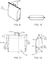
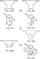
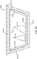
- Figure 9 is an elevational view of the expanded grocery carrier bag 20 in a closed expanded state 20C, illustrating an exterior look of an embodiment of the expanded grocery carrier bag 20 in its closed state 20C.
- Figure 10 is a top plan view of the expanded grocery carrier bag 20 in the closed expanded state 20C.
- Figure 11 is a front view of the expanded grocery carrier bag 20 in the closed expanded state 20C.
- Figure 12 is a side view of the expanded grocery carrier bag 20 in the closed expanded state 20C, as seen in the direction of arrow B in figure 11 .
- an embodiment of the collapsible handle-carryable grocery carrier bag 20 is suitable for use in an air atmosphere environment.
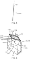
- the carrier bag has a collapsed state 20A (See Figs 2, 3 and 4 ) for enabling transportation of the carrier bag in a substantially flat state.
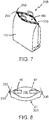
- the carrier bag may also have an expanded state 20B, 20C such that the carrier bag, in its expanded state, provides an interior storage space 100 ( Fig 6 and 8 ) for transporting chilled and/or frozen grocery packages 40 (See Fig 8 ).
- the carrier bag may comprise a paper layer being shaped and folded so as to form
- the wall panels i.e. the front wall panel 110, the back wall panel 120, the two side wall panels 130A and 130B and the bottom panel 140 may cooperate to form said interior storage space 100.
- the interior storage space 100 may be of a volume larger than 10 litres in the expanded state of the carrier bag. The volume depends on the dimensions of the bottom panel and the wall panels.
- a rim portion 150 of the wall panels 110, 120, 130A and 130B facing away from the bag bottom panel 140 may provide a bag opening 160 ( Fig 6 & 7 ).
- the carrier bag may further comprise a first handle 170A being associated with said rim portion 150, 150A of said front wall panel S1A.
- the first handle 170A may be shaped and dimensioned to allow gripping by a human hand such as to enable convenient carrying of the grocery carrier bag. In some businesses where carrier bags are utilized, it is considered necessary for a carrier bag to be provided with a handle, since a handle-carryable grocery carrier bag is considered to be a fundamental customer convenience requirement.
- a grocery bag which is capable of being carried by means of a handle, or a pair of handles, is considered to be a fundamental customer convenience requirement.
- the carrier bag is therefore advantageously provided with an integrated handle, or an integrated pair of handles such that a handle-carryable grocery carrier bag is supplied.
- the carrier bag may have an open expanded state 20B ( Figs 6 & 7 ) for loading and/or unloading grocery packages to be transported, and a closed expanded state 20C (See Figs 9 & 10 ).
- the carrier bag In its closed expanded state 20C, the carrier bag may provide a substantially closed interior storage space 100.
- the bag opening 160 ( Fig 6 & 7 ) is a closable opening which, in the closed expanded state ( Fig 9 ) of the carrier bag may cooperate with the wall panels and the bottom panel so as to minimize or prevent entry of air from the environment into the interior storage space.
- the substantially closed interior storage space may advantageously be used for transporting chilled and/or frozen grocery packages, since the carrier bag, in its closed expanded state 20C, may exhibit a very good ability to maintain a low temperature of chilled or frozen items that are stored in the closed interior storage space.
- the advantageous cold keeping properties of embodiments of the container 20 is believed to rely on a combination of container features.
- the choice of material forming the front wall panel S1A, the back wall panel S1B, the side wall panels S2A, S2B; and the bottom panel contributes to the advantageous cold keeping properties.
- the design of the container walls is not limited to the above shape. Instead, the word wall is to be understood as a material forming the boundaries of the interior storage space of the container 20.
- the wall or walls of the container 20 forms the boundaries of the interior storage space for transporting chilled and/or frozen goods.
- the kraft paper layer 180 may have a surface weight in the range between 40 and 240 grams per square metre, and a density lower than 1200 kg per cubic metre.
- the surface weight of the kraft paper may be selected in dependence on the tensile strength to which the bag will be exerted when in use.
- a carrier bag may be produced in various sizes, such as e.g. a ten litre bag, a twenty litre bag, a thirty litre bag, a forty litre bag, or a fifty litre bag.
- kraft paper with as low surface weight as 40 g/square metre and a density lower than 1200 kg/cubic metre, at least for the small size bags of ten or twenty litre storage space, when the small size bag will be used for carrying lower weights.
- the maximum weight of the goods to be transported will, to some extent, be limited by the size of the bag.
- the Kraft paper layer has a surface weight of between 100 and 140 grams per square metre, and a density lower than 1000 kg/cubic metre.
- the inventors have considered the following in terms of choice of kraft paper quality:
- Figure 12B illustrates a portion of a kraft paper wall layer 180B, having a wall thickness t 1 and a density D 1 .
- the proportion of air in the kraft paper is about 40%.
- NTP i.e. Normal Temperature and Pressure dry air has a density of 1,204 kg/m 3 .
- air has a very low heat conductivity of about 0,024 W/(m K), and thus an increased proportion of air in the kraft paper proves to have a dramatic effect in terms reducing heat conductivity of the kraft paper layer.
- An increased surface weight of the kraft paper in combination with a lower density leads to a yet a further increase of the internal thermal resistance of the kraft paper wall.
- the kraft paper may be as low as 350 kg/m 3 .
- the inventors also cocluded that, it is preferable to select a kraft paper density higher than 350 kg/m 3 and surface weight higher than 60 grams per square meter.
- the inventors concluded that when the kraft paper density is 350 kg/m 3 , or higher than 350 kg/m 3 , and the kraft paper surface weight is higher than 60 grams per square meter, the Kraft paper wall of a kraft paper bag 20 advantageously provides a relatively high thermal resistance while also having a relatively high tensile strength.
- an appropriate size container should the selected.
- the bag size should be selected sufficiently large that the chilled goods fits inside, of course, but for optimum chill conserving ability of the bag, the chilled or frozen goods should preferably fill more than 30 % of the inside volume of the container 20.
- the container size should be selected sufficiently small so that, when packed with the cold or frozen goods, the cold or frozen goods fill up more than 30 % of the inside volume of the selected container 20.
- a good filling degree of a bag 20 is between 25% and 75%.
- the step of determining the desired tensile strength therefore may begin by assuming a 100% filling degree of goods having a mean density of about 0,5 kg per cubic decimetre or 50% filling degree of goods having a mean density of about 1 kg per cubic decimetre.
- a bag with an interior storage space of X litres should be designed to enable carrying a mass of at least 0,5 ⁇ X kg. Therefore, in one example it is assumed that a bag with an interior storage space of 10 litres should be designed to enable carrying a mass of at least 5kg. Likewise, a bag with an interior storage space of 20 litres may be designed to enable carrying a mass of 10kg, and so on. A bag with an interior storage space of 50 litres would according to this example be able to carry a mass of 25 kg.
- the bag comprises walls with a layer of wall material, the layer having a pre-determined tensile strength.
- said pre-determined tensile strength exceeds 0.133 N/mm 2 .
- said pre-determined tensile strength exceeds 0.267 N/mm 2 .
- said pre-determined tensile strength exceeds 0.399 N/mm 2 .
- said pre-determined tensile strength exceeds 0.533 N/mm 2 .
- said pre-determined tensile strength exceeds 0.667 N/mm 2 .
- the mass m is in principle the added mass of the bag and the goods carried in it. In practice, the mass of the goods might be predominant.
- the area A is an area over which the force F is distributed.
- FIG. 62a shows schematically a bag to illustrate the principle of determining the area A.
- the bag has a rectangular bottom with length and width of d 1 and d 2 , respectively.
- the bag comprises two handles.
- the bag further comprises two sheets for distributing the forces applied to the handles to the outer walls of the bag.
- the handles and the sheets for distributing the forces applied to the handles to the outer walls of the bag are the same on the front side and on the back side of the bag.
- Each sheet for distributing the forces applied to the handles to the outer walls of the bag is substantially rectangular and has a length and a width of d 4 and d 3 , respectively.
- Fig.62b shows, schematically, a side view of the handle, the bag and the sheet for distributing the forces applied to the handles to the outer walls of the bag.
- the sizes in Fig. 62b are not to scale, neither in relation to Fig. 62 , nor in relation to each other.
- Fig. 62b three thicknesses are illustrated, wherein a first thickness d 5 denotes the thickness of the handle, d 6 denotes the thickness of the sheets for distributing the forces applied to the handles to the outer walls of the bag, and d 7 denotes the thickness of the wall of the bag.
- d 5 denotes the thickness of the handle
- d 6 denotes the thickness of the sheets for distributing the forces applied to the handles to the outer walls of the bag
- d 7 denotes the thickness of the wall of the bag.
- d 3 180mm
- d 5 0.8mm
- d 6 0.1mm
- d 7 0.123mm.
- a kraft paper layer advantageously provide a good tensile strength and it also contains a certain amount of air or gas, thus contributing to the thermal insulation capacity of the container 20.
- Non-woven material may comprise slender fibers which are not woven or knitted but are kept together in other ways, such as by entanglement.
- Non-woven materials may include textile-like materials.
- the wall panels and or bottom panel of the container 20 may be made of one of the above listed materials (a Non-woven material, a Conventional textile, a film of foamed or porous thermoplastic, a film of foamed or porous rubber).
- bag size should be selected such that an air gap is allowed to form between the inner surface of the container and the outer surface of the cold or frozen goods.
- an air gap is advantageous in that the air gap renders extra insulation against the exterior environment, which may be warm.
- the middle portion of interior the surface of the bag bottom may be marked so as to indicate that it is a loading zone for chilled goods. This advantageously indicates to the user of the chill container that goods to be transported should preferably be placed within the indicated area for optimum chill conserving effect during transport. In this manner a simple marking of the bag bottom will be indicative of a three-dimensional bag loading zone volume within the bag, the bag loading zone volume being separated from the side wall(s) of the bag by an air gap.
- the middle portion of interior the surface of the bag bottom may be marked so as to indicate that it is a loading zone for chilled goods (as described above), and the strips may be attached and positioned to the bag walls so that when goods-to-be-transported is stacked on the marked loading zone on the bag bottom (which may lead to the marked bottom area being covered), the paper strips will still indicate the loading zone volume of the bag.
- the container size should be selected sufficiently small so that, when packed with the cold or frozen goods, the cold or frozen goods fill up more than 30 % of the inside volume of the selected container 20, while also allowing for an air gap to be formed between the cold or frozen goods and the inner surface of the container wall or walls.
- the polymer membrane layer 190 may comprise Low-density polyethylene (LDPE).
- LDPE Low-density polyethylene
- the LDPE membrane may have a density in the range from 910 to 940 kg/m3.
- the LDPE- membrane layer may have an air permeability of less than 0,35 ⁇ m/(Pa ⁇ s) in accordance with ISO 5636-3:2013.
- the polymer membrane layer 190 may alternatively comprise a biodegradable plastic such as a cellulose-based plastics (eg cellulose acetate).
- a biodegradable plastic such as a cellulose-based plastics (eg cellulose acetate).
- the polymer membrane layer 190 comprising a biodegradable plastic as defined above may be extrusion coated on a kraft paper layer.
- biodegradable plastic as defined above may be dispersion coated on a kraft paper layer.
- the dispersion coated biodegradable plastic can advantageously be recycled in a conventional paper recycling process.
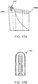
- Figure 13 is a cross-sectional view of the wall material at a point indicated by arrow C in FIG 11 .
- Figure 13 is illustration of an embodiment of material layers at rim portion 150 of the front wall 110 at a position where the handle strip is attached to the front wall 110.
- the water impermeable and water vapour impermeable membrane 190 may be provided on the side of the kraft paper layer 180 facing the interior of the bag, as illustrated in Figure 13 .
- the water vapour impermeable membrane 190 is distributed over substantially all of the surface on one side of the paper layer 180.
- the water vapour impermeable membrane 190 comprises a polymer.
- the polymer layer 190 may be a layer of PE or Polyethylene.
- the first handle 170A may comprise a paper strip formed in a U-shape and having two paper strip end portions 200A and 210A.
- the paper strip end portions 200A and 210A of the first handle 170A may be attached to said rim portion 150 of said front wall panel 110, S1A.
- the paper strip end portion 210A may be attached to the membrane 190 by means of a glue layer 220.
- a first substantially planar reinforcement sheet 230 (See Fig 6 and 13 ) having a certain size may be provided in order to distribute the lifting force from the first handle paper strip end portions to a larger surface area of the front wall panel 110, S1A.
- the first substantially planar reinforcement sheet 230 may have a first sheet surface 230A and a second sheet surface 230B on opposite sides of the substantially planar reinforcement sheet 230.
- the first reinforcement sheet 230 may be attached to the paper strip end portion 210A of the first handle 170A and to said rim portion 150 of said front wall panel 110, S1A such that said paper strip end portion 210A of the first handle 170 is located between the front wall panel 110, S1A and the reinforcement sheet 230.
- the first surface 230A of the first reinforcement sheet 230 faces the paper strip end portion 210A of the first handle 170A and said rim portion 150 of the front wall panel 110, S1A.
- the first surface 230A of the first reinforcement sheet 230 may be bonded to the paper strip end portion 210A and to said rim portion 150 of said front wall panel 110 S1A so as to distribute lifting force from said paper strip end portions to said front wall panel via said first reinforcement sheet.
- the bag opening 160 is closable by means of a mechanical interlock 240, or closure device 240 attached to said rim portion 150.
- the closure device 240 in the closed expanded state of the carrier bag, cooperates with the wall panels and the bottom panel to minimize or prevent air from the environment from entering the interior storage space.
- the closure device 240 includes a first elongated closure element 240A, and a second elongated closure element 240B.
- the second substantially planar reinforcement sheet being bonded to the second sheet surface of the first substantially planar reinforcement sheet advantageously achieves two effects.
- the elongated closure device is thereby attached to the bag wall, and on the other hand the second substantially planar reinforcement sheet 250A also acts to distribute lifting force from said first substantially planar reinforcement sheet to said front wall panel via said second reinforcement sheet, the lifting force originating from the handle when the bag is carried by lifting the handle 170A (See Fig 6 ).
- the second substantially planar reinforcement sheet 250A may have a lower edge 270, and the second substantially planar reinforcement sheet 250A may have a physical extension of between 10% and 30% of the height of a wall panel 110.
- the paper strip end portions of the first handle and said first reinforcement sheet are sized and dimensioned so as to withstand a force exceeding 100 Newton.
- a Kraft paper layer of more than 140 grams per square metre may be advantageous for certain uses of the carrier bag, but the embodiment of the grocery carrier bag intended for use in grocery stores, allowing end user customers to pack their groceries into the bag, will preferably have a Kraft paper layer of 140 grams per square metre, or less than 140 grams per square metre. This is because the Kraft paper layer of more than 140 grams per square metre may be experienced to be a bit too stiff, whereas a Kraft paper layer of 140 grams per square metre or less than 140 grams per square metre will be more flexible, and thus more convenient to handle.
- FIG 15 is an illustration of Kraft Pulp Fibres.
- the kraft paper layer may comprise a plurality of Kraft Pulp Fibres 270 which are arranged one above the other so as to form plural air gaps within the kraft paper layer.
- the kraft paper layer comprises a plurality of Kraft Pulp Fibres which are arranged one above the other so as to form plural air gaps within the kraft paper layer, and at least some of the Kraft Pulp Fibres have a length in the range between 1 and 3 mm and/or a width in the range between 10 and 50 micrometer. At at least some of the plural air gaps have a volume exceeding 200 000 cubic micrometers according to that embodiment.
- the substantially water vapour impermeable membrane is bonded to the side of the kraft paper layer facing the outside of the bag.
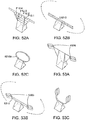
- Figure 17A is a perspective view of a part of the closure device 240 shown in figure 14 .
- Figure 17B is a side view of the closure device 240.
- a movable pressure device 280 also referred to as "runner" 280, may be provided, according to an embodiment, for the purpose of forcing the protrusion of the second elongated closure element 240B to enter into the elongated cavity of the first elongated closure element 240A.
- This solution provides for an advantegeosly simple handling of the bag 20.
- a customer having loaded chilled groceries into the bag 20, may easily close the bag by simply sliding the movable pressure device 280 from one edge 290 to the other edge 300 (see Figure 14 in conjunction with Figure 8 or 7 ) . In this manner, the customer may easily close and substantially seal the interior storage space from the environment so as to minimize or prevent entry of air from the environment into the interior storage space
- the grocery bag 20 exhibits an ability to maintain the frozen state of initially frozen groceries during a remarkably long time, thereby maintaining the initial quality and/or flavour of the frozen food stored in the bag.
- Figure 18 is an illustration of an embodiment of an insulator device.
- the insulator device may be arranged and positioned on at least a portion of the bottom panel in the interior storage space 100 of the bag 20 so as to reduce heat transfer through the bottom panel.
- the insulator device comprises a piece of material being shaped and adapted to provide cellular air cushions so as to reduce heat transfer through said bottom panel.
- the insulator device comprises at least one layer of a plastic material. This solution advantageously enables the insulator device to withstand a damp or wet environment without absorbing water.
- the insulator device comprises BubbleWrap®.
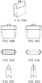
- Figure 19 is an elevational view of an embodiment of the expanded grocery carrier bag 20 in an open expanded state 20B, placed next to an embodiment of a collapsible grocery inner chill bag 400.
- Figure 20 is an elevational view of an embodiment of a handle-carryable grocery carrier chill bag package 450.
- the chill bag package 450 illustrated in figure 20 includes an expanded grocery carrier bag 20 in the closed expanded state 20C, and the collapsible grocery inner chill bag 400, in its expanded state; the inner chill bag 400 being shaped and dimensioned to fit inside of the carrier bag 20.
- An embodiment of the handle-carryable grocery carrier chill bag package 450 may thus comprise a collapsible handle-carryable grocery carrier chill bag 20 and a collapsible grocery inner chill bag 400.
- the handle-carryable grocery carrier chill bag package in use, may include include the collapsible grocery inner chill bag 400 in its closed expanded state ; and the collapsible handle-carryable grocery carrier chill bag 20 in its closed expanded state, wherein the collapsible grocery inner chill bag is placed in the interior storage space 100 of the collapsible handle-carryable grocery carrier chill bag 20.
- This solution advantageously enables the packing of frozen grocery packages in the second interior storage space 410.
- This solution therefore enjoys a high thermal resistance from a frozen grocery package in the second interior storage space to the environment outside of the outer handle-carryable grocery carrier bag, since any air inside of the first interior storage space 100 functions as insulation between the second interior storage space and the environment outside of the outer handle-carryable grocery carrier bag.
- the interior of the bag 20, when in use, may be initially chilled by the low temperature of frozen or chilled grocery packages which are placed in the interior storage space 100. Although this is sufficient for maintaining the frozen or chilled state of frozen or chilled grocery packages for an extended period of time, the inventor realized that this time period may be further extended.
- the handle-carryable grocery carrier chill bag package 450 may, in use, further comprise a means 460 for cooling the interior 100 of the bag 20 and/or for cooling the second interior storage space 410.
- a cooling agent According to an embodiment of the means 460 for cooling the interior of the bag, there is provided a cooling agent.
- a piece of dry ice is an embodiment of such a cooling agent.
- Dry ice is the solid form of carbon dioxide.
- the chemical formula of carbon dioxide is CO2.
- a carbon dioxide molecule comprises two oxygen atoms bonded to a single carbon atom. It is colourless, non-flammable, and slightly acidic.
- Carbon dioxide can change from a solid to a gas with no intervening liquid form, through a process called sublimation.
- the opposite process is called deposition, where CO2 changes from the gas to solid phase (dry ice).
- sublimation/deposition occurs at -78.5 °C. Its enthalpy of sublimation is 571 kJ/kg (25.2 kJ/mol).
- the density of dry ice varies, but usually ranges between about 1.4 and 1.6 g/cm3.
- the low temperature and direct sublimation to a gas makes dry ice an effective coolant, since it is colder than water ice and leaves no residue as it changes state.
- the Dry Ice cooling agent there is provided pellets of dry ice, the size of the pellets being suitable for placing in the interior storage space 100 of the bag 20, when the bag 20 is in use as a chill bag.
- the dry ice pellets gradually change from a solid form to gaseous carbon dioxide with no intervening liquid form (sublimation) there is a corresponding energy consumption of 571 kJ/kg which causes a decrease of the temperature of any food packages surrounding the dry ice pellets.
- the dry ice may be provided in a piece of a suitable size, dependent on the amount of refrigeration desired.
- a single piece of dry ice may comprise one kilogram of dry ice.
- a single piece of dry ice may comprise e.g. 10 grams of dry ice.
- a single piece of dry ice may comprise e.g. 100 grams of dry ice.
- Such relatively small pieces of dry ice may be referred to as dry ice pellets.
- One or several dry ice pellets may be used simultaneously in the interior storage space 100 of the chill bag 20, dependent on duration of the period of time it is desired to keep the interior storage space 100 at freezing temperatures.
- a pressurized container holding a gas there is provided a pressurized container holding a gas.
- the container may hold pressurized air.
- the container may hold pressurized carbon dioxide gas.
- the container may be embodied by a cylinder.
- the cooling means may comprise a cylinder in which carbon dioxide gas is stored under pressure.
- the pressurized cylinder may be provided with a valve.
- the valve of the pressurized cylinder is adjustably settable between a completely closed state and a state in which the valve allows pressurized carbon dioxide gas to flow out from the pressurized cylinder.
- the valve is settable to a predetermined amount of openness, so as to attain a suitable amount of cooling effect.
- This slight increase in the pressure of the air inside of the chill bag 20 may advantageously further minimize or prevent entry of air from the environment into the interior storage space 100 of the chill bag 20.
- a valve in one of the walls of the bag 20 so as to prevent any buildup of any significant pressure in the bag 20.
- the valve may be a check valve adapted to allow passage of air only in the direction from the interior storage space 100 of the chill bag 20 to the surrounding environment.
- the cylinder containing pressurized carbon dioxide gas may interact with the chill bag 20 such that when a grocery package comprising frozen food is transported in said interior storage space the grocery bag is adapted to minimize or prevent entry of air from the environment into the interior storage space (100) by providing a controlled flow of gaseous carbon dioxide from the interior storage space to the environment.
- This solution may advantageously further minimize or prevent the occurrence of condensation within the interior storage space (100).
- cylinder containing pressurized carbon dioxide may be kept in a freezer at a temperature of about - 18 °C (degrees Centigrade). The carbon dioxide pressure in the pressurized cylinder may then be about 18 bar.
- the low initial temperature pressurized cylinder will also contribute to maintaining a frozen or chilled state of any grocery package comprising frozen food being transported in the interior storage space 100 of the chill bag 20.
- the pressurized carbon dioxide cylinder may contain e.g. 2 kg of carbon dioxide at 0,75 kg of carbon dioxide per litre of cylinder volume.
- the pressurized carbon dioxide cylinder may contain carbon dioxide at 0,67 kg of carbon dioxide per litre of cylinder volume.
- the pressurized carbon dioxide cylinder may contain less than 0,5 kg of carbon dioxide at a filling level of less than 0,75 kg of carbon dioxide per litre of cylinder volume.
- the pressurized carbon dioxide cylinder may initially contain less than 0,5 kg of carbon dioxide at a filling level of less than 0,67 kg of carbon dioxide per litre of cylinder volume.
- One or several pressurized carbon dioxide cylinders may be used simultaneously in the interior storage space 100 of the chill bag 20, dependent on duration of the period of time it is desired to keep the interior storage space 100 at freezing temperatures.
- an ice pack for retaining a frozen temperature for an extended period of time.
- the ice pack may comprise a sachet containing a gel that can be frozen and that retains a frozen temperature for an extended period of time.
- an ice pack may comprise a sachet made of PE material, and the gel filled sachet may have a weight of about 100 grams (0,1 kg).
- One or several ice packs may be used simultaneously in the interior storage space 100 of the chill bag 20, dependent on duration of the period of time it is desired to keep the interior storage space 100 at freezing temperatures.
- a collapsible carrier bag wherein said collapsible carrier bag has a collapsed state for enabling transportation of the carrier bag in a substantially flat state, and an expanded state for transporting food items in a carrier bag enclosure which, in the expanded state of the carrier bag, has a volume larger than 10 litres.
- Said carrier bag further can have a front wall panel S1A, a back wall panel S1B, two mutually opposing side wall panels S2A, S2B.
- Said carrier bag further can have a substantially rectangular bottom portion BP. Said wall panels and said bottom portion BP of said carrier bag can cooperate to form an enclosure. This enclosure can be a carrier bag enclosure.
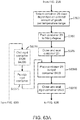
- FIG. 31 shows a method 1305 for providing a transport container.
- Said transport container can be a collapsible carrier bag.
- the method 1305 will be illustrated in several examples which can be seen in Fig. 40-49 .
- Fig. 40 , 41 , and 42 show examples of pre-determined patterns. The pre-determined patterns there can then be formed and folded to provide a bag as will be described in the following.
- solid lines show the outer borders of the pre-determined patterns and possible cuts in these patterns.
- solid lines show the borders of the bag, or the bag-to-be respectively, or parts thereof, as seen from the viewing direction. In the three-dimensional views, solid lines can also show lines where the bag or the bag-to-be has been folded.
- the dashed lines show possible folding edges in Fig. 40-47 .
- dashed lines show elements or parts of elements which are covered by another element when seen in the viewing direction.
- the areas delimitated by dotted lines in Fig. 40-47 show areas which are described in the following. These areas might be delimited by folding edges and/or borders of a sheet or other physical borders.
- FIG. 40n is an alternative to what is shown in Fig. 40f .
- One of the big differences between Fig. 40 and Fig. 41 are said triangles 4030a, 4030b, 4030c, 4030d which are not present in Fig. 41 .
- the pattern in Fig. 41 could, however be formed and folded in a corresponding way as is shown in Fig. 40a-40m when one would remove the triangles from these figures. Since the triangles are well visible in Fig. 40a-40m and it would be clear how to fold the pattern when it does not have triangles, an explicit sketch of the folding procedure of Fig. 41 is omitted. In Fig. 40a-40n , only examples of the most important folding edges for the current steps of the method 1305 are shown for not overloading the figures.
- FIG. 40 These shown folding edges correspond preferably to the folding edges in Fig. 40 .
- the dashed arrows indicate the directions towards which areas along the shown folding edges can be folded in preferred examples.
- Straight solid arrows without reference numbers show directions in which the bag or the bag-to-be can be pulled or pushed, depending on the direction of the arrows.
- the area which is delimitated by the uppermost horizontal solid line and by the folding edges F3a, F3c, and F4a can at the end of method 1305 form the front panel S1A of the bag.
- the area which is delimitated by the lowermost horizontal solid lines and the folding edges F3b, F3d, and F4b can at the end of method 1305 form the back panel S1B of the bag.
- the two areas which are delimitated by the folding edges F6 on the left side of the figure, F3a, F4a, and by the uppermost horizontal line, respectively by the folding edges F6 on the left side of the figure, F3b, F4b, and by the lowermost horizontal line can at the end of method 1305 form one side panel S2A of the bag.
- the front panel S1A, the back panel S1B, and the side panels S2A, S2B can at the end of the method 1305 be delimitated on one side by the folding edge F4' and on another side by the leftmost solid vertical line in the figure.
- the front panel S1A can further be delimitated by the folding edge F3a and by the uppermost solid horizontal line of the figure.
- the back panel S1B can further be delimitated by the folding edges F3b and F3c.
- One side panel S2A can further be delimitated by the folding edges F3a and F3b.
- Another side panel S2B can further be delimitated by the folding edges F3c and F3d.
- the area delimitated by the folding edge F4', by the leftmost solid vertical line, by the uppermost horizontal line, and by the lowermost horizontal line can be part of the bottom portion BP of the bag.
- the outer portions of the bottom portion can at the end of method 1305 preferably be constituted by the folding edge F4'.
- the bottom portion BP will at the end of method 1305 have a substantially rectangular shape with the four sides of the rectangular shape being constituted by the section of F4' between the uppermost horizontal solid line and folding edge F3a, by folding edge F3a and folding edge F3b, by folding edge F3b and folding edge F3c, and by folding edge F3c and folding edge F3d, respectively.
- the method 1305 starts with step 1310. In step 1310 a sheet is provided.
- the provided sheet may be a substantially planar sheet of a multilayer material.
- Said substantially planar sheet has a first sheet surface and a second sheet surface on opposite sides of the substantially planar sheet.
- the multilayer material comprises preferably a layer of kraft paper having a substantially water vapour impermeable membrane bonded to at least one side of the kraft paper layer.
- step 1320 said sheet is cut. The cut is done according to a pre-determined pattern so that a resulting planar sheet has at least two edges.
- pre-determined patterns are given in Fig. 40-42 . In one example, the pre-determined pattern is substantially rectangular 4210. An example is shown in Fig. 42 .
- the pre-determined pattern comprises a substantially rectangular base pattern 4010, 4110, further comprising at least one protrusion 4020, 4120 at or close to at least one of the corners of the rectangular base pattern.
- said at least one protrusion 4020, 4120 is at least two protrusions 4020a, 4020c; 4020a, 4020b; 4120a, 4120c; 4120a, 4120b; ...
- said at least one protrusion 4020, 4120 is at least four protrusions 4020a, 4020b, 4020c, 4020d; 4120a, 4120b, 4120c, 4120d.
- two protrusions are at or close to two corners of the rectangular base pattern 4010, 4110.
- protrusions are at or close to the four corners of the rectangular base pattern 4010, 4110.
- said at least one protrusion 4020, 4120 comprises at least one protrusion having a substantially rectangular form, for example two protrusions 4020a, 4020c; 4020a, 4020b; 4120a, 4120c; 4120a, 4120b; ... or four protrusions 4020a, 4020b, 4020c, 4020d; 4120a, 4120b, 4120c, 4120d having a substantially rectangular form.
- a shorter side of said protrusions 4020, 4120 is preferably oriented parallel or at least substantially parallel to a long side of the substantially rectangular base pattern 4020, 4120.
- the protrusion 40 and Fig. 41 are L4020b and L4120b. It should be understood that also the other protrusions 4020, 4120 in these figures have corresponding long and short sides, which are however, not especially denoted in the figures for not overloading them. Even other shapes of protrusions or base patterns are possible.
- the protrusion has the shape of a rectangle 4020 with an attached triangle 4030. In one example one side of the triangle attaches the longer side of the rectangle and another side of the triangle attaches the longer side of the base pattern. An example can be seen in Fig. 40 . Such a pattern would allow a more convenient opening of the bag when in use. This can be seen in Fig.
- the protrusion attaches to a side panel S2A, S2B, or another part of the bag-to-be, along a longer line than without a triangle. This might distribute lifting forces better between handle/and or closure and the bag and thus increase the stability of the bag.
- shape of a substantially rectangular base pattern extends on its shorter sides into a bottle-like shape, i.e. a shape which narrows, and thus has a diameter which is shorter than the short side of the substantially rectangular base pattern, and then extends again.
- the pre-determined pattern comprises at least one or two openings 4510.
- This at least one or two openings 4510 have preferably such a size that the four fingers of a human hand, preferably of a grown-up person, easily can get through at least one or two of these openings.
- the openings 4510 are then intended to provide the handle 4520, 4530 when the carrier bag is used.
- the pre-determined shape comprises two additional rectangular or substantially rectangular shapes 4040.1, 4040.2; 4140.1, 4140.2 which are attached to the substantially rectangular base pattern 4010, 4110.
- the two additional rectangular shapes 4040.1, 4040.2; 4140.1, 4140.2 are preferably also situated in such a way that at least half 4010b, 4010d, 4110b, 4110d of each long side 4010a, 4010b; 4010c, 4010d; 4110a, 4110b; 4110c, 4110d of the rectangular base pattern 4010, 4110 is not covered by the two additional rectangular shapes 4040.1, 4040.2; 4140.1, 4140.2.
- the not-covered half 4010b, 4010d, 4110b, 4110d of each long side of the rectangular base pattern 4010, 4110 is preferably connected and thus not intercepted by one of the two additional rectangular shapes 4040.1, 4040.2; 4140.1, 4140.2.
- the pre-determined pattern is preferably arranged in such a way that an overlap 4050, 4150, 4250 will be provided in step 1340.
- This overlap 4050, 4150, 4250 will be constituted by a first overlap area 4050a, 4050c, 4050e, 4050g; 4150a, 4150c; 4250a and a second overlap area 4050b, 4050d, 4050f, 4050h; 4150b, 4150d; 4250b.
- the first overlap area 4050a, 4050c, 4050e, 4050g; 4150a, 4150c; 4250a is preferably on the first sheet surface and the second overlap area 4050b, 4050d, 4050f, 4050h; 4150b, 4150d; 4250b preferably on the second sheet surface.
- the first and the second overlap area are preferably equal in size.
- One example of how an overlap will be provided is given in step 1330.
- said two additional rectangular shapes 4040.1, 4040.2; 4140.1, 4140.2 are one part of the overlap which is referred to in step 1340.
- the first sheet surface parts of the two additional rectangular shapes 4040.1, 4040.2; 4140.1, 4140.2 are, for example, a first overlap area 4050a, 4050c; 4150a, 4150c.
- an optional step 1331 and/or an optional step 1330 is performed.
- said sheet is formed or folded into a substantially tubular shape.
- the tubular shape is preferably such that the at least two edges overlap so as to allow a first overlap area 4250b of the first sheet surface to meet a second overlap area 4250a of the second sheet surface.
- the first sheet surface forms then an interior surface of the-bag-to-be.
- the reference 4250a could denote the first overlap area and the reference 4250b the second overlap area.
- Performing a forming or folding into a tubular shape can give the advantage that only one first overlap area 4250b and only one second overlap area 4250a are needed, thus only requiring a small number of production steps when these areas are attached to each other.
- said sheet is folded.
- said folding is performed in such a way that substantial parts of the base pattern overlap each other.
- at least 60% of the area of the base pattern overlaps each other.
- the amount of the area of the base pattern which overlaps each other is at least 70%, at least 80%, at least 90%, or at least 95%.
- step 1340 the first overlap area 4050a, 4050c, 4050e, 4050g; 4150a, 4150c; 4250a is attached to the second overlap area 4050b, 4050d, 4050f, 4050h; 4150b, 4150d; 4250b.
- An example is shown in Fig. 40b .
- the second overlap area 4050b, 4050d, 4050f, 4050h; 4150b, 4150d; 4250b can be constituted a part of the second sheet surface of the rectangular base pattern 4010, 4110, which part has approximately the same shape as said two additional rectangular shapes 4040.1, 4040.2; 4140.1, 4140.2.
- Said part is preferably constituted by the part of the rectangular base shape 4010, 4110 which can be achieved when mirroring said two additional rectangular shapes 4040.1, 4040.2; 4140.1, 4140.2 at the long sides 4040.1L, 4040.2L; 4140.1L, 4140.2L of the rectangular base pattern 4010, 4110 and on said line F1 in step 1331.
- the attaching is in one example done by gluing. In one example the attaching is done by melt-bonding. In one example, parts or the whole of the protrusions 4020a, 4020b, 4020c, 4020d; 4120a, 4120b, 4120c, 4120d are attached on overlap areas.
- some of the protrusions for example 4020a, 4020b; 4120a, 4120b have a different length than the other protrusions, for example 4020c, 4020d; 4120c, 4120d.
- the protrusions with the longer length can then provide a first overlap area and the protrusions with the shorter length can then provide a second overlap area.
- the first overlap area corresponds in one example to the area formed by the length difference between the protrusions with the longer and the shorter length.
- the second overlap area can in this example correspond to an area of corresponding size at the protrusions with the shorter length. This is described in more detail in relation to 43.
- step 1350 the sheet is formed or folded so as to form outer surfaces of the transport container.
- Said outer surfaces are in one example a front panel S1A, a back panel S1B, and two mutually opposing side panels S2A, S2B of the-bag-to be.
- An example is shown in Fig. 40c-40f .
- folding edges corresponding to those in Fig. 40c and Fig. 40d are present on the other side of the bag-to-be. These corresponding folding edges are shown in Fig. 40 .
- the corresponding edges are preferably folded as well, as is indicated by the dashed arrows in Fig. 40c and Fig.
- the forming or folding of the sheet is done in such a way that a substantially cuboid-like base-form is achieved. In one example this is done in such a way that a substantially parallelepiped-like base-form is achieved.
- the surface area of the parallelepiped-like base-form comprises preferably four substantially rectangular areas. These four substantially rectangular areas are on four different sides of the parallelepiped-like base-form.
- the front panel S1A and the back panel S1B of the bag-to-be are preferably two mutually opposing sides of the parallelepiped.
- the two mutually opposing side panels S2A, S2B of the-bag-to be are preferably two mutually opposing sides of the parallelepiped.
- the front panels S1A, the back panel S1B, and the two mutually opposing side panels S2A, S2B have substantially rectangular shapes.
- each side panel S2A, S2B attaches to a side of the front panel S1A and one side of each side panel S2A, S2B attaches to a side of the back panel S1B.
- the attaching sides between the side panels S2A, S2B and the front panel S1A and the back panel S1B comprise folding edges F3, for example folding edges F3a, F3b, F3c, and F3d.
- a mid-fold F6 is provided in each of the side panels S2A, S2B.
- the mid-fold F6 of a side panel runs in one example in a direction substantially parallel to a fold where that side panel S2A, S2B connects with the front panel S1A, for example fold F3.
- the folding edge F4 usually will be continuous or close to continuous when the providing of the bag is finished, the folding edge F4 might not be continuous at this point yet.
- the folding edge F4 does in one example comprise two folding edges F4a and F4b.
- the folding is preferably in such a way that the folding is towards the first sheet surface at the front panel S1A and the back panel S1B.
- the folding is preferably in such a way that the folding is towards the second sheet surface along the side panels S2A, S2B.
- a bottom panel will be provided in addition to the other four panels S1A, S1B, S2A and S2B.
- step 1360 a bottom is created.
- Fig. 40e - Fig. 40j The creation of the bottom is done in by forming or folding the multilayer sheet so as to create a bottom portion BP of the bag-to-be.
- the folding along the folding edge F4' is towards the first sheet surface.
- additional four folding edges F5' for example F5a', F5b', F5c', and F5c' are provided. These four addition folding edges F5' preferably start at the interception of the folding edge F4' with the folding edges F3. These four additional folding edges F5' preferably enclose an angle of substantially 45 degrees to the folding edge F4'.
- These four folding edges are situated on the bottom portion BP. In one example, after folding along the four folding edges F5, F5', overlapping areas due to that folding are attached, for example via bonding or gluing.
- the distance between the folding edge F4' and a bottom edge of the sheet is larger than the length of the folding edge F4' on the side panels S2A, S2B.
- Creating a bottom of a pre-determined pattern like in Fig. 40 or in Fig. 41 has the advantage that there will be no gap at the bottom of the bag.
- the bottom portion BP comprises a connected substantially rectangular part of the sheet which covers the whole bottom portion BP. This is in contrast to the bottom portion from a pre-determined pattern like in Fig. 42 , where one first has to overlap some parts of the pre-determined pattern to cover the whole bottom portion.
- An advantage of having no gap in the bottom portion is that no way is provided for moisture from the ground to enter the space of the bag through the bottom portion BP. Further, an air exchange will be prevented as well.
- creating the bottom area comprises adding additional elements to the bag to be.
- This additional element can for example be an insulator device.
- the insulator device can comprise a piece of material being shaped and adapted to provide cellular air cushions so as to reduce heat transfer through said bottom panel BP.
- the insulator device comprises paper and a substantially water vapour impermeable material.
- the substantially water vapour impermeable material of the insulator device comprises at least one layer of a polymer material.
- the insulator device can, for example, be put in the bag through the bag opening.
- the insulator device can have substantially the same from and size as the bottom panel BP. In such a way it can cover the whole bottom panel BP after inserting it.
- the insulator device can be attached to the bottom panel BP from the inside of the bag.
- the insulator device can also be put loosely on the bottom panel BP from the inside of the bag.
- the insulator device can also be attached to the bottom panel BP from the outside of the bag.
- step 1370 the semi-manufactured bag is collapsed. An example is given in Fig. 40k-m . This collapsing is done by folding along a folding edge where the front panel S1A connects with the bottom panel, for example along folding edge F4.
- the collapsing step is performed in such a way that a side panel mid-fold F6 is bent inwardly so as to cause one interior surface of each side portion to face an interior surface of the front panel, and to cause another interior surface of each side portion to face an interior surface of the back panel.
- two or four collapsing folding edges F7, F7', for F7a and F7b, or F7a', F7b', F7c', and F7d' are provided in step 1370 or a previous step such as step 1331, step 1350, or step 1360.
- These collapsing folding edges start preferably at the interceptions between the folding edge F4, F4' and the folding edges F3.
- collapsing folding edges F7 preferably start either both at said interceptions at the front panel, or at said interceptions at the back panel.
- Two collapsing folding edges F7 are preferred when the side panel mid-fold F6 is bent outwardly, and four collapsing folding edges F7' are preferred when the side panel mid-fold F6 is bent inwardly.
- the collapsing folding edges F7, F7' enclose an angle of substantially 45 degrees with the folding edge F4, F4', and are situated on the side panels S2A, S2B.
- the collapsing folding edges F7, F7' stop at the interceptions with the side panel mid-fold F6.
- the bag-to-be is folded along the collapsing folding edges F7, F7'.
- the folding along the collapsing folding edges F7 is outwardly.
- the folding along the collapsing folding edges F7' is inwardly.
- an additional collapsing folding edge F8, F8' is provided. What has been said before regarding that the collapsing folding edges F7, F7' can be provided at an earlier step applies to the additional collapsing folding edge F8, F8' as well.
- This additional collapsing folding edge F8, F8' starts at a point where one of the collapsing folding edges F7, F7' stops at a side panel mid-fold F6.
- the additional collapsing folding edge F8, F8' is substantially parallel to the folding edge F4, F4' and stops at a point where another of the collapsing folding edges F7, F7' stops at the other side panel mid-fold F6.
- the additional folding edge F8, F8' will thus be situated either on the front panel S1A or on the back panel S1B.
- the folding along the additional collapsing folding edge F8 is preferably in such a way that the outer part of the front panel S1A or the back panel S1B on both sides of the additional collapsing folding edge F8, F8' and close to said additional collapsing folding edge F8, F8' face each other.
- the outer part of the side panels S2A, S2B on both sides of the additional collapsing folding edge F8 and close to said additional collapsing folding edge F8 preferably face each other.
- step 1380 a closure and/or a handle is provided.
- the provided handle is a handle for allowing a user to carry the transport container.
- the handle is associated with the front panel S1A and the back panel S1B.
- the handle and/or the closure can also comprise additional elements which are attached to the sheet.
- the providing of the handle and/or a closure is quite independent of how the other parts of transport container have been provided. It should thus be understood that everything which is discussed in relation to the handle and/or the closure can be easily interchanged and/or combined between different embodiments and/or examples of transport containers which are described in this disclosure. Different kinds of providing the handle and/or the closure will soon be described.
- the method 1305 preferably ends after the optional step 1380.
- the container 20 may be shaped in such a manner that plural containers 20 can be piled on top of each other in a space conservative manner.
- An example of such a space saving shape is a cone shaped container.
- An example is shown in Fig. 34a and Fig. 34b .
- Fig. 34a a cone shaped container is shown in its expanded state in an elevated view.
- Fig. 34b a cone shaped container is shown in its flat state.
- plural cone shaped containers may be stacked by placing one cone container on top of the other such that the space required for storing ten containers is only slightly larger than the space required for storing one cone container.
- An example is shown in Fig. 35a and Fig.
- Fig. 35a and Fig. 35b are only for illustrating the principle. In practice, such containers might be stacked more tightly than in the figures.
- the container may be shaped as a truncated cone such that there is provided a substantially flat bottom area inside the truncated cone container, the cone wall leaning outwardly from the bottom area.
- An example is shown in Fig. 36a and Fig. 36b , where such a container is shown in an elevated view and in a flat view, respectively.
- truncated cone container may also be stacked or piled so that one container fits inside the next substantially identical container, thus enabling transport of a large number of stacked containers within a very small space.
- This feature of the container advantageously contributes to enable transporting containers 20 in bulk at a low cost.
- Fig. 32 shows a flowchart about a method 3200 of providing a handle.
- the method 3200 is in one example part of step 1380 of method 1305. In one example, the method 3200 is performed several times in step 1380, for example two times.
- the method 3200 comprises the step 3210.
- a handle is provided for the transport container. In one example, the handle is attached to the transport container, for example via gluing or bonding.
- the handle is attached to the interior side of the carrier bag. This is in one example done by attaching the handle to the first sheet surface. In one example, the handle is attached to the outer side of the carrier bag. This is in one example done by attaching the handle to the second sheet surface.
- the handle is preferably attached to the front panel S1A and/or the back panel S1B. It is, however, in principle possible to attach the handle to a side panel S2A, S2B as well.
- the handle can have a U-shape as comparable to the handle 4530 in Fig. 45a .
- the handle can have a cornered U-shape as comparable to the handle 4520 in Fig. 45b . Any other shape might work as well.
- the handle might be thicker than the sheet of the bag for providing more strength.
- the handle might be of the same material as the sheet.
- the handle might comprise several layers of the sheet of the bag. These several layers could be provided by folding one layer.
- the thickness of the combination of the handle 4610 and the support sheet 4620 will then equal the thickness of the handle 4610 and/or the support sheet 4620 alone.
- the support sheet 4620 is in one example attached to the front panel S1A and/or the back panel S1B.
- the handle 4610 is attached to the support sheet via a folding edge 4630.
- the handle is not directly attached to the front panel S1A and/or the back panel S1B. This allows a user to fold up and use the handle when the bag is in an expanded state, as is shown in Fig. 46b .
- the provided handle is a string 4710.
- the string 4710 can, for example, be attached close to the upper side 4060A, 4060B; 4160A, 4160B; 4260A, 4260B; 4660; 4760 of the front panel S1A and/or the back panel S1B.
- the term upper side relates in one example to the side of the front panel S1A and/or the back panel S1B which is upwards when the bag is in an upright position.
- the string 4710 can be placed substantially parallel to the upper side 4060A, 4060B; 4160A, 4160B; 4260A, 4260B; 4660; 4760 of the front panel S1A and/or the back panel S1B.
- the string 4710 can have a length that exceeds the width of the upper side 4060A, 4060B; 4160A, 4160B; 4260A, 4260B; 4660; 4760 of the front panel S1A and/or the back panel S1B.
- the string 4710 can have a length that exceeds twice the width of the upper side 4060A, 4060B; 4160A, 4160B; 4260A, 4260B; 4660; 4760 of the front panel S1A and/or the back panel S1B.
- the string 4710 is arranged to provide a closed loop 4713. This can, for example, be done by providing a knot 4720 between the two ends of the string 4710.
- the string can then be arranged substantially parallel to the upper side 4060A, 4060B; 4160A, 4160B; 4260A, 4260B; 4660; 4760 of the front panel S1A and/or the back panel S1B, so that the looped string has two portions 4711, 4712 of the string 4710 substantially parallel and preferably close to each other at the upper side 4160A, 4160B; 4260A, 4260B; 4660; 4760 of the front panel S1A and/or the back panel S1B.
- the length of the string is preferably so long that said two loops 4714, 4715 can be extended by moving the string which forms said two loops 4714, 4715, so that preferably at least a human hand, or at least the four fingers of a human hand can then grab through said two loops 4714, 4715.
- the string is attached vertically to the front panel S1A and/or the back panel S1B.
- the material of the string is in one example cotton twine.
- the string comprises plastics.
- a handle is provided by protrusions 4020a, 4020b, 4020c, 4020d; 4120a, 4120b, 4120c, 4120d of the pre-determined base pattern. This is described in more detail in relation to Fig 52a-c and Fig. 53a-c .
- said protrusions 4020a, 4020b, 4020c, 4020d; 4120a, 4120b, 4120c, 4120d are not part of the pre-determined base pattern. Instead, these protrusions are separate stripes which are attached to the base pattern. This attaching can in principle be done at any stage during method 1305, but is preferably done after step 1320.
- An advantage of attaching the stripes after the pre-determined base-pattern is cut is that the loss of material due to the cut pattern is minimised. When, for example, looking at Fig. 41 , one could cut the basically rectangular base-pattern 4110, maybe in combination with the two additional rectangular shapes 4140.1, 4140.2 out of one sheet of material.
- a stripe goes from the left edge of protrusion 4120a to the right edge of protrusion 4120c.
- Such a stripe would thus also cover parts of the side portions S2A, S2B and of the front panel S1A when attached to the rectangular base-pattern 4110.
- the attachment can be done of the first sheet surface of the pre-determined base-pattern or on the second sheet surface of the pre-determined base-pattern.
- protrusions 4020a, 4020b, 4020c, 4020d; 4120a, 4120b, 4120c, 4120d it should thus be understood that the same applies to protrusions 4020a, 4020b, 4020c, 4020d; 4120a, 4120b, 4120c, 4120d which are part of the pre-determined base pattern, as does apply for protrusions which are achieved via attachment of stripes. It should also be noted that said stripes do not necessarily have rectangular forms, but can have different forms for providing different forms of protrusions when attached to the pre-determined base pattern.
- the method 3200 continues with an optional step 3220.
- a reinforcement is provided.
- the provided reinforcement can be a reinforcement sheet.
- the reinforcement sheet can be substantially planar.
- the reinforcement is preferably attached to the same side of the front panel S1A and/or the back panel S1B as the handle. The attaching is, for example, done by gluing or bonding.
- the part of the handle which is attached to the front panel S1A and/or the back panel S1B is preferably situated between the front panel S1A and/or the back panel S1B and the reinforcement.
- the reinforcement attaches directly to parts of the handle and to the front panel S1A and/or the back panel S1B.
- the width of the reinforcement sheet is larger than the width of the handle.
- the width of the reinforcement sheet is at least 1.5 times the width of the handle.
- the width of the reinforcement sheet is preferably not larger than the width of the front panel S1A and/or the back panel S1B on which the reinforcement sheet is attached.
- One advantage when providing a reinforcement sheet is that the lifting force can be distributed from the handle to a larger area of the front panel S1A and/or back panel S1B than the overlap between the handle and the front panel S1A and/or back panel S1B.
- the reinforcement sheet has a certain height. This certain height is preferably larger than the height of the overlap between the handle and the front panel S1A and/or back panel S1B.
- the term overlap refers here to the area on which the handle is attached to the front panel S1A and/or the back panel S1B.
- the optional step 3220 is repeated. By doing this a second reinforcement is provided.
- This second reinforcement has preferably a larger area than the first reinforcement sheet.
- the width of the second reinforcement sheet is larger than the width of the first reinforcement sheet.
- the height of the second reinforcement sheet is larger than the height of the first reinforcement sheet. The second reinforcement sheet can then be attached to the first reinforcement sheet and the front panel S1A and/or the back panel S1B.
- the second reinforcement sheet covers a substantial part of the first reinforcement sheet, for example at least 80%, at least 90%, or at least 95%.
- the first reinforcement sheet is then in one example situated between the front panel S1A and/or back panel S1B and the second reinforcement sheet.
- One advantage when providing a second reinforcement sheet is that the lifting force can be distributed from the first reinforcement sheet to a larger area of the front panel S1A and/or back panel S1B than the overlap between the first reinforcement sheet and the front panel S1A and/or back panel S1B.
- the method 3200 can end after step 3220.
- Fig. 33 a flowchart of a method 3300 for providing closure means for a transport container is shown. The method 3300 is in one example part of step 1380 of method 1305.
- step 3310 at least one closure means is provided at the transport container.
- the closure means comprises said one or more protrusions 4020a, 4020b, 4020c, 4020d; 4120a, 4120b, 4120c, 4120d of the pre-determined base pattern. It is described in relation to Fig. 43 and Fig. 44 how these protrusions 4020a, 4020b, 4020c, 4020d; 4120a, 4120b, 4120c, 4120d can form the closure means.
- said reinforcement sheet is the second reinforcement sheet which has been described in relation to step 3220 of method 3200. In one example, said reinforcement sheet is another reinforcement sheet than the second reinforcement sheet which has been described in relation to step 3220.
- said closure device is a closure device 240 as described in relation to Fig. 14-17 .
- the closure device has a first elongated closure element 250A and a second elongated closure element 250B. The first and second elongated closure elements 250A, 250B, respectively can have an upper section and a lower section. The lower section is in one example attached to the bag-to-be. In one example, the lower section is attached to the front panel S1A and/or the bag panel S1B.
- the lower section can comprise a reinforcement sheet.
- the upper section is in one example not attached to the front panel S1A and/or the bag panel S1B.
- the upper section of the first and the second elongated closure element can have complementary patterns. These complementary patterns can be provided in such a way that the first and second elongated closure elements can interact to provide a closing between them, and thus a closing of the bag.
- the closing can, for example, be caused by a movable pressure device 280, also referred to as a "runner", or a "slider". Even a later opening of the bag can be provided by said runner/slider 280.
- Fig. 48a-d different kinds of attaching the closure device are described in relation to Fig. 48a-d .
- a handle 4820 is attached to the outer surface of the front panel S1A and/or the bag panel S1B.
- Fig. 48c +b the handle 4820 is attached to the interior surface of the front panel S1A and/or the bag panel S1B.
- Said attaching can be directly or include some other elements in between the handle 4820 and the outer and/or inner surface of the front panel S1A and/or the back panel S1B.
- the handle 4820 is integrated in the front panel S1A and/or back panel S1B as, for example, being described in relation to Fig. 45c .
- a reinforcement sheet 4810 is attached to the handle and to the same surface of the front panel S1A and/or the back panel S1B as the handle 4820 is attached to.
- the reinforcement sheet 4810 is attached to the outer surface of the front panel S1A and/or the back panel S1B and covers a lower part of the handle 4820.
- Fig. 48 the handle 4820 is integrated in the front panel S1A and/or back panel S1B as, for example, being described in relation to Fig. 45c .
- a reinforcement sheet 4810 is attached to the handle and to the same surface of the front panel S1A and/or the back panel S1B as the handle 4820 is attached to.
- the reinforcement sheet 4810 is attached to the inner surface of the front panel S1A and/or the back panel S1B and covers a lower part of the handle 4820.
- this distance is zero or basically zero.
- this distance is at least one centimetre, for example 1 cm, 2 cm or 3cm, 4 cm, or 5 cm.
- a runner/slider 4880 or another element which can cause the actual closing is shown in Fig. 48a-e as well. In the following, when referring to an elongated closure element, this could be the first or the second elongated closure element.
- an elongated closure element 4870a is attached on the outer side of the front panel S1A and/or the back panel S1B.
- the attachment is done in such a way that the handle is outside the elongated closure element 4870a, thus not intercepting a closing action by the runner/slider 4880.
- the elongated closure element 4870a has in one example a width which is longer than the width of the upper side of the front panel S1A and/or the back panel S1B.
- a first and a second elongated closure element can be attached to each other at an overlapping area outside the front panel S1A and/or the back panel S1B, thus providing an especially good closing of the transport container since the air exchange will be well prevented at the corners of the upper side of the front panel S1A and/or the back panel S1B.
- an elongated closure element 4870b is attached on the inner side of the front panel S1A and/or the back panel S1B.
- the handle will automatically be outside the elongated closure element 4870b, thus not intercepting a closing action by the runner/slider 4880.
- the elongated closure element 4870a has preferably a width which is substantially the width of the upper side of the front panel S1A and/or the back panel S1B. Thus a good enclosing of the transport container will be provided.
- an elongated closure element 4870c is attached on the inner side of the front panel S1A and/or the back panel S1B. The attachment is done in such a way that the handle is in between the elongated closure element 4870c and the front panel S1A and/or the back panel S1B, thus not intercepting a closing action by the runner/slider 4880.
- the elongated closure element 4870c has preferably a width which is substantially the width of the upper side of the front panel S1A and/or the back panel S1B.
- an elongated closure element 4870c is attached on the inner side of the front panel S1A and/or the back panel S1B. The attachment is done in such a way that the handle is in between the elongated closure element 4870d and the front panel S1A and/or the back panel S1B, thus not intercepting a closing action by the runner/slider 4880.
- the elongated closure element 4870d has preferably a width which is substantially the width of the upper side of the front panel S1A and/or the back panel S1B. The difference between Fig.
- Fig. 48c and Fig. 48d is that the vertical distance of the lower part in Fig. 48d is larger than in Fig. 48c .
- Fig. 48d the whole reinforcement sheet is covered by the lower part of the elongated closure element.
- the attached lower side of the elongated closure element provides an additional barrier for air to prevent air exchange between the inside and the outside of the bag when the bag is in a closed state.
- an elongated closure element 4870e is attached on the inner side of the front panel S1A and/or the back panel S1B. Since the handle is part of the sheet which provides the front panel S1A and/or the back panel S1B, the handle is not intercepting a closing action by the runner/slider 4880.
- the elongated closure element 4870e has preferably a width which is substantially the width of the upper side of the front panel S1A and/or the back panel S1B.
- the lower side of the lower part of the elongated closure element 4870e is not indicated, but can in one example be like in Fig. 48c or in Fig. 48d .
- a runner/slider 4880 is shown in Fig. 48a-e . This is, however, in one example not required.
- Any of the elongated closure elements 4870a, 4870b, 4870c, 4870d, 4780e could have a first pattern 5010 on the side which is faced to the interior of the bag.
- a corresponding elongated closure element which is situated at the panel which is opposite to the panel shown panel in Fig. 48a-48e can have a second pattern 5020 on its side which is faced to the interior of the bag.
- the second pattern 5020 can be complementary to the first pattern 5010.
- a closure element 4910 is provided at the inner and/or outer side of the front panel S1A and/or the back panel S1B.
- This closure element can have the size of a stripe and has preferable substantially the width of the upper side of the front panel S1A and/or the back panel S1B.
- the closure element 4910 can be attached to the front panel S1A and/or the back panel S1B. The attaching can be done by gluing or bonding.
- the closure element 4910 can be a glue strip.
- the closure element 4910 can be an adhesive tape.
- the glue strip and/or the adhesive tape can keep the front panel S1A and the back panel S1B close to each other, thus providing a closing of the transport container.
- the front panel S1A and the back panel S1B are kept attached to each other by the closure element 4910 once they touch each other via the closure element 4910.
- the closure element 4910 is only at the front panel S1A or only at the back panel S1B. This might be enough for providing a closure of the bag via adhesive forces.
- the closure element 4910 can comprise an additional strip of protection material (not shown in the figure). This strip can have substantially the same size as the glue strip/the adhesive tape.
- the additional strip can be provided in such a way that it has to be removed before allowing the glue strip/the adhesive tape to provide its adhesive force between the front panel S1A and the back panel S1B. This prevents the front panel S1A and the back panel S1B to stick permanently together when the transport container is in a flat state.
- the closure element 4910 is on the outside of the front panel S1A and/or the back panel S1B. Assuming the closure element 4910 being on the outside of the front panel S1A, the back panel S1B could have a larger vertical height than the front panel S1A.
- a folding edge could be provided at the back panel S1B. The folding edge can be substantially parallel to the upper side of the back panel S1B.
- the folding edge could be situated at a distance from the upper side of the back panel S1B. Said distance could be approximately the distance of which the vertical height of the back panel S1B differs from the vertical height S1A of the front panel.
- the folded section of the back panel S1B can then be put over the front panel S1A so that it covers the outer part of the front panel which comprises the closure element 4910. In that way a closure of the bag can be provided as well.
- the closure element 4910 could also or instead be situated at the inner side of the folded part of the back panel S1B.
- the role of the front panel S1A and the back panel S1B can also easily be interchanged.
- the closure element 4910 can also be an element which allows closing the transport element with the help of an external closure element.
- the closure element 4910 can comprise a welding strip.
- the welding strip can be formed from a layer of PE.
- the welding strip can be made of a weldable material so as to enable closing the bag opening by heat welding such that entry of air into the bag interior is minimized or prevented.
- Said external element is in one example a sealing element, for example a hot sealing element. It could also be an impulse sealing element.
- the external element could be a welding element.
- the external element could be a so-called hot weld pistol.
- the closure element is part of sheet which is provided for being cut in a method like method 1305.
- the closure element 4910 is not an additional element which has to be attached to the front panel S1A and/or the back panel S1B, but is already part of the front panel S1A and the back panel S1B.
- the closure element 4910 is in one example of the same material as the front panel S1A and/or the back panel S1B. According to an embodiment the water vapour impermeable membrane 190 forms the welding strip.
- the closure element 4910 can also be provided at the outside of the front panel S1A and/or the back panel S1B when the front panel S1A and the back panel S1B have the same size. This might be advantageous when providing a closure as described in relation to Fig. 43 and Fig. 44 .
- Other examples of closure elements are presented in Fig. 51a +b.
- the closure element 5170a is provided by a tape or another adhesive material.
- This tape could be folded over the upper side of the bag after the upper sides of the front panel S1A and the back panel S1B are brought together. This provides an easy method to close the bag.
- the length of the tape could be longer than the width of the bag. Then the outer edges of the tape could be put together to attach each other. This provides a better closing of the bag.
- the closure element 5170b is provided by a clamp.
- the clamp 5170b could, for example, press the upper parts of the front panel S1A and the back panel S1B together. This pressing together could for example be caused by the form and the stiffness of the clamp 5170b.
- the clamp 5170b can have a width which is longer than the upper width of the bag.
- the form of the clamp 5170b can be different from what is shown in Fig. 51b . Although shown without a handle, it would be no problem to provide a handle in Fig. 51a and Fig. 51b , for example a handle as in Fig. 48a or in Fig. 46 . What is said in relation to Fig. 51a and Fig. 51b can also be combined with other examples of the disclosure.
- a tape 5170a or a closure element 5170b could, for example, be combined with a folded closing as described in relation to Fig. 43 and Fig. 44 . In that case it might in one example be advantageous to provide one or several clamps with shorter widths than the upper width of the front panel S1A and/or the back panel S1B.
- a clamp might be enough to keep a closing as indicated in Fig. 44 at its place so that it will not unfold automatically.
- Fig. 51c Yet another possibility is described in Fig. 51c .
- the front panel S1A and/or the back panel S1B could have a protrusion 5110c extending to its upper side.
- This protrusion 5110c could be substantially rectangular.
- the protrusion could have an opening 5120c.
- the opening 5120c could be such that it provides a handle. How openings can provide handles has been described before.
- a closure element 5170c could be provided at a part of the protrusion 5110c which is between the opening 5120c and the front panel S1A and/or back panel S1B .
- This closure element 5170c could have any of the properties of the closure element 4910 which has been described before. Especially the closure element 5170c could provide adhesive force. The closure element 5170c could also be thus that a closure could be provided with the help of an external element which has been described before.
- the method 3300 can end after step 3310.
- Fig. 39 a method of providing a bag with a closure is illustrated.
- the closure which is provided there can, for example, be the closure as illustrated in Fig. 48a .
- This closure can be with or without the runner/slider 4880.
- a plurality of produced bags 3910a, 3910b, 3910c, ... can be provided. In the shown example the plurality of produced bags 3910a, 3910b, 3910c, ... is in an extended state.
- plurality of produced bags 3910a, 3910b, 3910c, ... equally well could be in a flat state.
- a long stripe 3920 of what should be the elongated closure element 4870a is provided. This long stripe 3920 could comprise to stripes, one for the front panel S1A and one for the back panel S1B.
- One or several cutting elements 3930 can be provided to cut the long stripe 3920 in between the plurality of plurality of produced bags 3910a, 3910b, 3910c, ..., for example along the dotted lines as indicated in Fig. 39 . Said one or more cutting element 3930 is only schematically drawn in Fig. 39 .
- Said one or more cutting element 3930 are in one example at a substantially fixed position, at least in one or two dimension, and the plurality of produced bags 3910a, 3910b, 3910c, ... can be transported in relation to said one or more cutting element 3930.
- the described way of providing a bag with a closure can facilitate mass production.
- additional ways of providing a handle and/or a closure are described. Some of the steps can be part of any of the methods 1300, 1302, 1305, 3200, and/or 3300. It should also be stressed that what is described here can be well combined with what have been described before.
- Figure 43 shows an example of a section of a transport carrier-to-be. This section can, for example be a section of the sheet which is cut in step 1320 of method 1305.
- Fig. 43 shows thus a protrusion 4320 at a front panel S1A. As has been described before, that protrusion can also be attached at a later state. It does thus not need to be part of the pre-determined pattern which is cut in step 1320. It should also be stressed that the protrusion does not need to be rectangular.
- the protrusion 4320 could also have the shape of a rectangular with an attached triangle as shown in Fig. 40 , or any other shape.
- An edge part 4330 of the protrusion 4320 could be attached to a corresponding part of another protrusion of the base pattern.
- this other protrusion can for example be protrusion 4120b or protrusion 4120c.
- This attaching can be done by gluing or bonding.
- the protrusion could be folded or bent, for example along a folding line/bending start line F10. This allows providing a handle.
- a handle on the side panel S2A can be provided.
- a handle on the front panel will be provided.
- the edge part 4330 could be much larger than indicated in Fig. 43 .
- the edge part is in one example basically the whole protrusion. This might provide an especially strong handle. In an alternative example no protrusion 4120b and/or 4120c is provided.
- the edge part 4330 can then be attached to a corresponding area on another element of the bag. This corresponding area can, for example be an area at the side panel S2A or at the front panel S1A close to where the protrusion 4120b and/or 4120c could have been attached.
- At least one additional folding edge F11 can be provided at the protrusion 4320.
- the at least one additional folding edge F11 comprises in one example four additional folding edges F11.1, F11.2, F11.3, F11.4.
- This at least one additional folding edge can continue through the front panel S1A and/or one or both of the side panels S2A, S2B as well.
- the at least one additional folding edge F12 comprises in one example three additional folding edges F12.1, F12.2, F12.3.
- the additional folding edges F12 comprise preferably between one and ten folding edges.
- the additional folding edges F11 comprise preferably between one and ten folding edges.
- Corresponding folding edges can be provided at the back panel S1B and/or at protrusions thereof. In the following it will only be described how the protrusion 4320 and the front panel S1A can be folded.
- the folding edges F11, F12 are in one example substantially parallel and at a distance to the upper side of the front panel S1A and/or the protrusion 4320.
- the protrusion 4320 and or the front panel S1A is folded along the folding edges F11, F12 in the same direction.
- the folding is thus in one example always in the direction of the first sheet surface of the front panel S1A/the protrusion 4320. In another example, the folding is always in the direction of the second sheet surface of the front panel S1A/the protrusion 4320.
- the back panel S1B is put into contact with the front panel S1A. This could be done by putting the upper side of the back panel S1B in contact with the upper side of the front panel.
- the contact between the back panel S1B and the front panel S1A is along the enclosed areas FS1, FS2, FS3.
- the folding is in one example done in the way that the enclosed area FS1 between the upper side of the protrusion 4320/the upper side of the front panel S1A and the uppermost folding edge, in the shown example F11.1, faces the enclosed area FS2 between the uppermost folding edge F11/F12, in the shown example F11.1, and the second most upper folding edge F11/F12, in the shown example F11.2.
- the contact between the front panel S1A and the back panel S1B and/or the corresponding protrusions is preferable kept throughout the folding procedure, so that the first sheet surface of the front panel S1A and the back panel S1B and/or the corresponding protrusions always touch each other.
- an enclosed area FS2 between the uppermost folding edge F11.1 and the second uppermost folding edge F11.2 is folded towards the enclosed area FS3 between the second uppermost folding edge F11.2 and the third uppermost folding edge F11.3.
- the enclosed area FS1, and preferably its counterpart on the back panel S1B, will thus be situated between the areas FS2 and FS3.
- the folding can be continued along several or all of the folding edges F11/F12. Fig.
- Fig. 44 shows a schematic example of how the result of thus a folding can look like.
- Fig. 44 can be obtained when looking into the direction of the arrow D in Fig. 43 .
- Fig. 44 it is shown how the enclosed areas FS1, FS2, ... can be arranged after the folding procedure.
- the horizontal lines in Fig. 44 are only sketched for clarity reason to provide an intermediate space between the enclosed areas FS1, FS2, ...
- the horizontal lines are in reality preferably not there, or at least much more narrow in relation to the vertical lines. In one example there is basically no space between the enclosed areas FS1, FS2, ...
- the lines in Fig. 44 present preferably the front panel S1A and the back panel S1B together, i.e.
- every line represents both the front panel S1A and the back panel S1B, where the front panel S1A is on one side of the line and the back panel S1B on the other side of the panel.
- a folding provides a closure of the bag.
- This has the advantage that no additional closing element is needed.
- a closure element 4910 as described in relation to Fig. 49 can be provided at the enclosed area FS7 for attaching the enclosed area FS5 to it. This additionally increases the closing capacity of the fore mentioned folding method.
- the folding edges FS11/FS12 are sketched at equal distance. This is, however, not a prerequisite.
- FIG. 44 A folded area has a certain thickness and the next folded area needs to compensate for this thickness when folded around the previous area, as is indicated by the horizontal lines in Fig. 44 .
- FIG. 44 An example of how the folding described in relation to Fig. 43 and Fig. 44 can be applied to a bag made out of the base pattern in Fig. 40 is shown in Fig.
- a starting point could be a bag in an opened position as shown in Fig. 40j .
- This bag could be closed by bringing the upper portions of the front side panel S1A and the back side panel S1B together as shown in Fig. 52a .
- the bag in Fig. 52a can be folded along folding edges F12.1-F12.4 as described in relation to Fig. 43 and Fig. 44 .
- a bag as shown in Fig. 52b will be achieved.
- the protrusion in a folded state 5210 could be turned to from a handle 5210c as shown in Fig. 52c .
- the combined length L5210 of the protrusion in a folded state 5210 is at least four times larger than the length of the upper side of the front panel S1A and/or back panel S1B. This has the advantage that no additional elements except the sheet providing the pre-determined base pattern have to be provided for forming the handle and/or closure of the bag.
- the outer ends of the protrusion in a folded state 5210 can be attached to each other.
- a bag with the triangles not attached to each other, as shown in Fig. 44n could be folded in the same way.
- a bag starting with a base-pattern as shown in Fig. 41 could provide handle and/or closure in an analogous way as shown in Fig. 52a-c .
- the combined length L5210 of the protrusion in a folded state 5210 is only slightly larger than the length of the upper side of the front panel S1A and/or back panel S1B. Then a handle 5210c of the kind shown in Fig. 52c will not be provided.
- the parts of the protrusions in the folded state 5210 are folded towards the front panel S1A and/or the back panel S1B.
- the upper length of the front panel S1A and/or the back panel S1B in relation to Fig. 52b and Fig. 52c it should be understood that this is the upper length in the state shown in Fig. 52b and Fig. 52c .
- This length could differ from the upper length of the front panel S1A and/or the back panel S1B in Fig. 52a , since the upper length there now has been folded away.
- Fig. 40a-n and Fig. 52a-c only are schematically.
- Fig. 53a-c shows yet another example, where Fig. 53a corresponds to Fig. 52a , and so on. In this example, only an outer part of the protrusions 4020a, 4020b, 4020c, 4020d; 4120a, 4120b, 4120c, 4120d is attached to each other.
- the other parts of the protrusions 4020a, 4020b, 4020c, 4020d; 4120a, 4120b, 4120c, 4120d are preferably not attached to each other, thus allowing the protrusions to form at least one opening 5305.
- the folding between Fig. 53a and Fig. 53b is done analogous to the folding from Fig. 52a to Fig. 52b .
- a protrusion in a folded state 5310 looks then similar to what is shown in Fig. 52b , except that the protrusion in a folded state 5310 has said at least one opening.
- this at least one opening 5305 can be used as a handle for the bag. This is indicated in Fig. 53c . What is said in relation to Fig. 52a-c regarding size of areas applies here as well.
- Providing handles as shown in Fig. 53c has the advantage that no additional elements are needed for the handle.
- the carrier bag 20 may advantageously be used by on-line shops, for delivery of frozen or chilled groceries which have been ordered e.g. via the Internet.
- the advantageous ability of the bag 20 to preserve the frozen or cold state of groceries for an extended length of time may enable a reduction in the cost for delivery of frozen or chilled groceries.
- FIG. 21 shows a schematic block diagram of an embodiment of a system for delivering groceries according to an embodiment of the invention.
- Reference numeral 500 relates to a client location with a computer 510 having a user interface 520 for enabling a client, such as e.g. a person wanting to buy goods, to access the Internet.
- the computer 510 has a communications port 520 for bi-directional data exchange.
- the communication port 520 is connectable to a communications network 530, e.g. via a data interface 19.
- the communications network 530 may be the world wide internet, also known as the Internet.
- the communications network 530 may also comprise a public switched telephone network.
- a server computer 540 is also connected to the communications network 530.
- the server computer 540 may comprise a database 560, user input/output interfaces 570 and data processing hardware 580, and a communications port 590.
- the server computer 540 is located on a server location 592, which is geographically separate from the client location 500.
- the server location 592 may be in a first city, such as the Swedish capital Swedish, and the client location may be in another city, such as Berlin, Germany.
- the server location 592 may be in a first part of a town and the client location may be in another part of the same town.
- the server location 592 may also be referred to as supplier part 592, or supplier part location 592.
- the server computer may be part of an on-line business entity 595 for the sales and delivery of goods that needs to be kept chilled, cold or frozen.
- the on-line business also includes a storage facility 600 for goods 40.
- a storage computer 610 is connected to the communications network 530.
- the storage computer 610 may comprise user input/output interfaces 620 and data processing hardware 630, and a communications port 640.
- the storage facility 600 also comprises one or several storage rooms 650.
- the storage room 650 has a controlled environment, in that the temperature and the relative humidity of the air in the storage room 650 is controlled so that it is kept within certain predetermined ranges.
- the goods may comprise a plurality of different types of goods, and the goods may be sorted into different temperature ranges TI, TII, TIII, and TIV, each type of gods being stored in a corresponding storage room 650 TI , 650 TII , 650 TIII , and 650 TIV having a temperature in accordance with the corresponding goods temperature range TI, TII, TIII, or TIV (See Figure 22 ).
- the temperature in each storage room is set 650 TI , 650 TII , 650 TIII , and 650 TIV in accordance with a lowest acceptable goods temperature range for the corresponding goods.
- each storage room 650 TI , 650 TII , 650 TIII , and 650 TIV is set in accordance with a lowest acceptable goods temperature range for the corresponding goods, and the relative humidity of the air is also set to a lowest acceptable value dependent on the type of goods in that storage room.
- the relative humidity of the air is set to a value equal to or lower than lower than 40% RH in a room storing chilled or frozen goods so as to reduce or minimize the rate of condensation.
- Figure 22 is a schematic block diagram of an embodiment of a storage facility 600 comprising plural storage rooms 650 TI , 650 TII , 650 TIII , and 650 TIV .
- the facility 600 may also comprise a goods loading room 660.
- the goods loading room 660 may be arranged so that a storage room 650 is accessible directly from the goods loading room 660.
- the ambient air temperature in goods loading room 660 is kept lower than +18 degrees Centigrade.
- the air humidity is advantageously kept low in the environment where chilled or frozen goods is to be packed into containers 20 so as to eliminate or minimize the occurrence of condensation or frosting on chilled or frozen goods.
- the relative air humidity is kept lower than 40% RH.
- the relative air humidity is kept lower than 20% RH. In this connection it may be noted that the occurrence of condensation can cause significant heating of chilled, non-frozen, goods.
- an object and an advantageous feature of the invention is to eliminate or minimize warming of chilled or frozen goods during packing into a container 20 by eliminating or minimizing the occurrence of frosting and/or condensation on chilled or frozen goods.
- the ambient air temperature in goods loading room 660 is therefore kept lower than +10 degrees Centigrade, and the air humidity is also kept low in the environment where chilled or frozen goods is to be packed into containers 20 so as to eliminate or minimize the occurrence of condensation or frosting on chilled or frozen goods.
- the relative air humidity is kept lower than 30% RH.
- the relative air humidity is kept lower than 20% RH.
- the storage facility 600 also comprises storage of containers 20 for the transport of chilled or frozen goods.
- the containers 20 may be carrier bags 20 for the transport of chilled or frozen goods.
- the containers 20 may be provided in plural predetermined sizes, such as e.g. five different sizes.
- the interior storage space volume of the containers 20 sizes may comprise e.g. 10 litres, 20 litres, 30 litres, 40 litres and 50 litres.
- the facility 600 may comprise plural storage rooms 650 TI , 650 TII , 650 TIII , and 650 TIV , as mentioned above.
- the Goods storage facility # may keep a stock of goods 40 I at a first cool temperature within the first temperature range T I .
- the first temperature range may be 15-18 degrees Centigrade.
- Such goods 40 I may comprise grocery such as fresh produce, such as fruit or mushroom, which may be provided in separate portion sized packages or containers 40A. Thus, some goods may be provided at a first, cool, temperature range T I of about 15-18 degrees Centi
- the second cold non-freezing temperature range may be a range of about +6 to +8 degrees Centigrade.
- the cold non-freezing temperature range may be a range of about +1 to +4 degrees Centigrade.
- the third temperature range TIII may be a freezing temperature range of e.g. between -18 degrees to - 22 Centigrade.
- some goods may be provided at a fourth freezing temperature range T IV which is colder than the third range.
- the fourth range may be e.g. of between -25 to -40 degrees Centigrade.
- Providing frozen goods within such a low temperature range advantageously extends the time required for the frozen goods to warm towards a minimum freezing temperature T frMin .
- the minimum freezing temperature T frMin may be e.g. -10 or -4 degrees Centigrade.
- the value of the minimum freezing temperature T frMin depends on the type of goods.
- the inaccuracy range T ra may be a narrow span of a few degrees.
- the inaccuracy range T ra may be a narrow span of e.g. less than two degrees.
- the duration from the packing of the chilled or frozen product into the chill conserving container 20 until the goods has reached a certain higher temperature T ch2 depends on the initial temperature T ch1 of the chilled or frozen goods.
- a lower initial goods temperature T ch2 will increase the duration T COOL during which the goods is kept below a certain limit value T chlimit .
- a lower initial goods temperature T ch2 will enable a longer acceptable transport time of the chilled or frozen goods.
- FIGS 23A and 23B and 23C show a schematic block diagram of an embodiment of a method of delivering chilled or frozen goods according to an embodiment of the invention.
- the left flow chart F10 illustrates actions performed by means of a client location computer 510.
- a client such as e.g. a person wanting to buy goods, places an order for chilled and/or frozen goods by causing the client location computer 510 to communicate with the server computer 540 located at the server location 592.
- the client may thus place an order for a certain amount A of chilled and/or frozen goods to be delivered to a delivery destination DD.
- the server computer 540 may thus be adapted to receive an order, as indicated by step S300 in the right hand side flow chart F20 in Fig 23A .
- the server computer 540 may also include functionality for debiting, and for confirming receipt of the order.
- the server computer 540 may be adapted to sort the order information according to the goods temperature ranges (step S310).
- the server computer 540 may, in a step S320, transfer a delivery instruction DI to the storage computer 610 at the storage facility 600.
- the delivery instruction DI may comprise information about the amount of each piece of goods ordered and information indicative of the delivery destination DD.
- the delivery instruction DI may also be indicative one or plural goods temperature ranges associated with the ordered goods.
- the delivery instruction DI may be received by the storage computer 610 at the storage facility 600.
- the storage computer 610 may be adapted to create a packing instruction PI.
- the packing instruction may include information about the amount of each piece of goods ordered. It is noted that the step S310 may be performed by the storage computer 610, as an alternative to being performed by the server computer.
- the storage computer 610 may be adapted include structured information in the packing instruction PI so that an approximate volume and/or an approximate mass of the goods within an individual temperature range TI, TII, TIII, or TIV is indicated by the packing instruction PI. In dependence on the information in the packing instruction PI the storage computer 610 may generate an indication of a suitable type and/or suitable size of transport container for the ordered goods.
- the containers 20 may be provided in plural predetermined sizes, such as e.g. five different sizes.
- the interior storage space volume of the containers 20 sizes may include plural container volume sizes V1, V2, V3, V4, V5.
- the container volumes may include V1, V2, V3, V4, V5 being mutually different sizes such as e.g. 10 litres, 20 litres, 30 litres, 40 litres and 50 litres.
- the storage computer 610 may deliver the packing instruction PI to a relevant user input/output interface 620 I , 620 II , 620 III , or 620 IV dependent on the volume and/or mass indicated for goods within an individual temperature range TI, TII, TIII, or TIV is indicated by the packing instruction PI.
- the packing instruction PI includes an indication that X kg of goods within the fourth temperature range TIV is to be packed
- the instruction may be sent to the corresponding user input/output interface 620 IV (See Figure 22 ).
- a user input/output interface 620 I , 620 II , 620 III , and/or 620 IV may include a display.
- the display 620 I , 620 II , 620 III , and/or 620 IV may be adapted to be read by a person whose task it is to move the indicated amount of goods from the indicated storage room 650 TI , 650 TII , 650 TIII , and/or 650 TIV into a container 20 having an indicated size V1, V2, V3, V4, or V5. It has been found that there is an optimum filling degree of a chill container 20.
- X kg of a certain chilled or frozen goods it is better to include the X kg in one chill container 20 than to split the X kg into smaller plural smaller amounts in different containers.
- all goods within a certain temperature range should preferably be collectively packed in as few containers as possible, while not exceeding the optimum filling degree of a chill container 20.
- the optimum filling degree allows for an air gap to form between the inner surface of the container 20 and the outer surface of the cold or frozen goods.
- the container is filled to a filling degree such that the chilled goods avoids physical contact with any side wall and with the inside of the closed upper surface, i.e. the sealed opening portion of the container 20.
- packing instruction PI may include information indicative of a recommended number container(s) 20 and recommended container size V1, V2, V3, V4, or V5 for goods within each temperature range (see step S350 in Figure 23A ) so as to allow for packing a minimum number of uniform goods temperature containers being filled to the optimum filling degree.
- the filling degree is determined so as to balance between conflicting requirements. If the filling degree is too small, the bag has too little content of chilled or frozen goods, the amount of stored negative energy is small rendering an undesiredly fast warming of the goods due the small amount of "cold energy".
- negative energy or"cold energy are used since a piece of chilled goods having a certain temperature absorbs energy , i.e. absorbs positive energy, in the process of increasing its temperature. The absorbed energy is the energy that may seep in via the walls of the closed and sealed container, by way of heat conduction through the walls.
- heating by condensation and/or frosting within the container 20 or bag 20 is eliminated or reduced, since entry of air is prevented or reduced as described elsewhere in this document, thereby basically rendering heat conduction through the walls the only remaining manner by which energy can seep into the interior of the container 20 or bag 20.
- the goods may fill the interior storage space to such an extent that the chilled or frozen goods may rest close to the side walls, or even touch the side walls, thereby reducing or eliminating an insulating effect gained by a gap between the side walls and the chilled or frozen goods placed at a centre position of the bottom panel of the bag.
- a good filling degree of a bag 20 is between 25% and 75%, according to an embodiment of the disclosure, so as to gain an insulating effect by a gap between the side walls and the chilled or frozen goods placed in the interior storage space. It has been found that it is preferable to have at least 2 kg of chilled or frozen goods in order to provide an amount of stored cold energy within the container 20, when the container 20 has a volume between 10 litres and 50 litres. More preferably, a container 20 having a volume between 10 litres and 50 litres, should be filled with at least 2,5 kg of chilled or frozen goods and the filling degree should preferably be less than 90%.
- a good filling degree appears to be between 30% and 70% of the bag volume.
- An optimum filling degree appears to be between 40% and 60% of the bag volume. According to a preferred embodiment the filling degree is between 45% and 55% of the bag volume.
- a container 20 having a bottom panel and side panels, is packed in a manner that allows an air gap to be formed between the side panels of the container 20 and chilled or frozen goods placed at a centre position of the bottom panel.
- a certain container 20 is filled with goods having mutually uniform temperature. This advantageously contributes to a substantially uniform temperature throughout the goods in that container 20, and it minimizes any temperature re-distribution between mutually different pieces of goods.
- one or plural containers 20 may be packed such that a minimum number of uniform goods temperature containers are filled to the optimum filling degree.
- the actual packing of containers 20 may be performed manually by a person receiving instructions from the user interface 620 in goods loading room 660.
- each container 20 may be closed and sealed, as indicated in step S370 ( Fig 23B ). This may also be done manually.
- closing and/or sealing of the container 20 may be performed. This may include heat welding, gluing, sealing by use of a tape, or by clamping. Closing and/or sealing of the container 20 may be also be performed by folding a rim portion of a bag 20.
- the container 20 may include a neck portion 662 of flexible material at the rim portion of the container wall(s), the flexible material being shaped and sized to allow a string 664 being placed around the neck portion so as to strangle the neck portion such that the container becomes substantially sealed.
- the storage computer 610 may deliver the packing instruction PI to a packing robot 670 (See figure 21 in conjunction with step S340 in Fig. 23A ).
- Figure 21 only shows one storage room 650, it is to be understood that there may be plural storage rooms 650 TI , 650 TII , 650 TIII , 650 TIV and one, several or all the storage rooms 650 TI , 650 TII , 650 TIII , 650 TIV may be provided with a packing robot 670, thereby enabling complete packing to be to performed in a cold and dry environment.
- the whole packing procedure may be performed within the respective storage room 650 TI , 650 TII , 650 TIII , 650 TIV having a controlled air temperature and a controlled air humidity.
- the ambient air temperature in goods loading room 660 is kept lower than +25 degrees Centigrade, and the air humidity is advantageously kept lower than 70% in the environment where chilled or frozen goods is to be packed into containers 20 so as to eliminate or minimize the occurrence of condensation or frosting on chilled or frozen goods.
- the relative air humidity is kept lower than 40% RH.
- the relative air humidity is kept lower than 20% RH.
- the container 20 should preferably be packed and sealed such that the air trapped within the container 20 has a relative humidity of less than 70% at an air temperature equal to the surface temperature of the goods during packing.
- the purpose of this feature is to minimize or eliminate the risk of condensation occurring within the container 20. Since the relative air humidity decreases in response to increased temperature, such relatively dry air being initially trapped in the container may not only avoid causing condensation, but it may also advantageously be able to absorb and dilute some humidity that may originate from the chilled goods or from a minor entry of ambient air during transport.
- the sealed container(s) 20 may be placed in or on a transport vehicle 680 for distribution to the delivery destination DD.
- the delivery destination may be the client location 500, or a geographically different place.
- the sealed container(s) is/are transported to the delivery destination DD in accordance with the information in the delivery instruction DI.
- the sealed container(s) 20 may have the ability to retain an initial low goods temperature for a long time due to the interaction of a number of cleverly combined features, as described elsewhere in this document, even when used in an air atmosphere environment having an ambient air temperature of more than +10 degrees Centigrade.
- the sealed container(s) 20 may have the ability to retain an initial low goods temperature for a long time also when the air atmosphere environment has an ambient air temperature of more than +20 degrees Centigrade or more.
- the sealed container(s) 20 may be delivered at the delivery destination DD in accordance with the information in the delivery instruction DI.
- the above described method of packing a container with chilled and/or frozen goods advantageously enables a very cost effective delivery of chilled and/or frozen goods.
- the above described method of packing a container with chilled and/or frozen goods advantageously enables transporting the chilled and/or frozen goods for an extended amount of time without requiring the use of a vehicle having active cooling or freezing devices.
- the air atmosphere environment had an ambient air temperature of +20degrees Centigrade and a relative humidity of 70% RH.
- a kraft paper carrier bag 20 was loaded with a mass of 4,7 kg frozen fresh water. It is to be noted that fresh water ice has a specific heat capacity of 2200 J/(kg *K).
- the test was performed in a room which was dark, except for short moments when a lamp was turned on for the purpose of inspecting the test objects. Hence, there was substantially no heat radiated onto the bags by lamps or sunlight. Since the kraft paper bag 20 was closed so as to minimize or prevent entry of air into the interior of the bag, the goods placed in the kraft paper bag 20 was prevented from being heated by frosting or condensation heating.
- the kraft paper bag 20 according to the embodiment used in the frozen fresh water test had:
- Figure 26 illustrates graphs of the temporal progression of temperature in two positions in a block of ice which was placed in a bag 20 according to the above described embodiment. As a comparison Figure 26 also illustrates graphs of the temporal progression of temperature in two positions in a block of ice which was placed in a bag according the prior art. Tables 5 and 3 (below in this document) provide measured values.
- kraft paper carrier bag 20 as an energy storage system
- gradual warming of the chilled or frozen goods within the container 20 is the result of a flow of energy from the warmer ambient air.
- a certain amount of energy is required.
- that energy may be referred to as sensible energy Es.
- Figure 26 and table 5 indicate that it took 2 hours and 6 minutes for the outer edge of the block of ice to increase its temperature by 20 degrees Kelvin, from -30 C to-10C, and it took 2 hours and 30 minutes for the centre of the same block of ice to increase its temperature by 20 degrees Kelvin, from -30 C to -10C.
- the test indicates that when the specific sensible energy Ess of the frozen goods is at least 10340 J, then it takes more than 2 hours to warm the frozen goods from -30 C to -10C when the ambient air temperature is constant at +20C.
- the kraft paper chill bag 20 is adapted to provide a thermal conductance, from the air atmosphere environment to the frozen goods in the interior storage space, such that when the product of the mass m of the frozen goods and the specific heat capacity of the frozen goods exceeds 10 000 Joule then it takes more than 2 hours to increase the mean temperature of the frozen goods by 20 K when the initial temperature difference between the warmer ambient air and frozen goods is 50K and the final temperature difference is 30K.
- 5kg of frozen meat may require more than 4 hours to increase its mean temperature by 20 K from -30 C to -10C when the frozen meat is placed in a chill bag 20 and the initial temperature difference between the warmer ambient air and frozen goods is 50K and the final temperature difference is 30K.
- the test first test described above appears to support this conclusion.
- the air atmosphere environment had an ambient air temperature of +20degrees Centigrade and a relative humidity of 70% RH.
- a kraft paper carrier bag 20 was loaded with a mass of 4,7 kg non-frozen fresh water. It is to be noted that non-frozen fresh water, in the temperature range from about +1C to about +10C, has a specific heat capacity of 4180 J/(kg *K).
- the third test was performed in a room which was dark, except for short moments when a lamp was turned on for the purpose of inspecting the test objects. Hence, there was substantially no heat radiated onto the bags by lamps or sunlight.
- the kraft paper bag 20 was closed so as to minimize or prevent entry of air into the interior of the bag, the goods placed in the kraft paper bag 20 was prevented from being heated by condensation heating.
- the kraft paper bag 20 according to the embodiment used in the chilled, non-frozen, fresh water test had:
- Figure 27 illustrates graphs of the temporal progression of temperature in two positions in a 4,7 litre canister of chilled non-frozen fresh water which was placed in a bag 20 according to the above described embodiment according to the third test. As a comparison Figure 27 also illustrates graphs of the temporal progression of temperature in two positions in a 4,7 litre canister of chilled non-frozen fresh water which was placed in a bag according the prior art. Tables 4 and 2 (below in this document) provide measured values.
- Some of the transport container embodiments described above comprise a sheet material which has been folded to form a carrier bag; the carrier bag having
- the bottom panel comprises folded portions wherein one sheet edge meets and overlaps another sheet edge.
- one sheet surface overlaps another sheet surface and the two overlapping sheet surfaces may be attached to one another, e.g. by gluing or melt-bonding, so as to form the bottom panel.
- a bottom panel including sheet edges See e.g. 721-725 in Fig. 54e .
- the bottom panel formed by folded sheet portions sometimes fails to prevent entry of air from the environment into the interior storage space. This may be due e.g. to the folded portions forming fissures or slits through which a fluid, such as air, may pass between the environment and the interior storage space of the bag.
- the entry of air having a certain air humidity may cause liquid water to be formed on a cold surface, such as on a surface of chilled goods in the interior storage space of the carrier bag. Since heat is released by the formation of liquid water or ice, the inventor realized that it is important to minimize or prevent entry of air from the environment into the interior storage space in order to prevent chilled goods from getting heated by the formation of liquid water or ice within the interior storage space.
- the method of manufacture of the bag has to be rational.
- the method of manufacture of the bag should be in conformance with the manufacturing methods applied by standard bag production machines, such as e.g. machines used for the manufacture of carrier paper bags of the type commonly found in grocery stores.
- An example of such a carrier bag is disclosed in DE 89 04 678 , the content of which is hereby incorporated by reference.
- the cover sheet 700 is sized and adapted to fit snugly on the interior surface of the bag bottom panel BP so that it covers any paper edges from the bag bottom panel BP on the interior surface.
- the edges can give cause to small openings through which air and thus heat can pass. Although being generally small, these openings might contribute greatly to the total amount of heat transferred from the outside of the cag to the interior of the bag.
- heat transfer from the outside of the transport container/carrier bag through the bottom portion BP to the inside of the bag, or vice versa is reduced.
- the cover sheet by covering the edges, can reduce this heat transfer.
- the edges in the bottom portion BP are in general at a distance from the perimeter, or from the outer lines, of the bottom portion BP. Thus, by covering the bottom portion BP, the edges are generally well covered as well.
- Placing the cover sheet 700 in the interior storage space of the bag may, however, require that the bag is available in an expanded position in order to make it possible to reach the bottom panel at the inside of the bag. Depending on how the bag is manufactured, this might require an extra step and/or might cause problems to reach the inner bottom panel BP from the inside due to the design of the bag.
- the cover sheet 700 is sized and adapted to fit on the outer surface of the bag bottom panel BP so that it covers any paper edges from the bag bottom panel BP on the outer surface of the bag.
- the outer surface of the bottom panel BP is usually easier to reach than the interior surface.
- the outer surface of the bottom panel BP can usually be reached both when the bag is in its collapsed state and when it is in its expanded state.
- An example of a bag where the outer surface of the bottom panel can be easily reached in the collapsed state of the bag is shown in Fig. 4 , Fig. 40M , or Fig. 46a .
- Fig. 4 An example of a bag where the outer surface of the bottom panel can be easily reached in the collapsed state of the bag is shown in Fig. 4 , Fig. 40M , or Fig. 46a .
- edges which can be covered by the cover sheet 700 are the edges 721-725 in Fig. 54e .
- the cover sheet 700 is a sheet of a membrane which is water vapour impermeable, or substantially water vapour impermeable.
- the membrane of the cover sheet 700 comprises a polymer, such as PE or polyethylene. Any other material described in relation to the water impermeable membrane 190 of the wall can be used as well.
- the cover sheet 700 is of the same material as the bottom panel BP and/or the side panels S1A, S1B, S2A, S2B of the bag. This can reduce production costs since the number of different materials for producing the bag is produced.
- the cover sheet 700 comprises a layer of kraft paper and a layer of the water vapour impermeable membrane.
- the layer of kraft paper is oriented against the side of the bottom panel. This might facilitate gluing since kraft paper often is simpler to glue than a water impermeable membrane. This is especially advantageous if the side of the bottom panel BP which is oriented to the cover sheet 700 comprises predominantly kraft paper as well.
- the layer of water impermeable membrane is oriented against the side of the bottom panel. This might facilitate attaching via melting since a water impermeable membrane might comprise a material which can attach to another material through melting, such as said polymers. This is especially advantageous if the side of the bottom panel BP which is oriented to the cover sheet 700 comprises predominantly a water impermeable membrane as well.
- the cover sheet 700 comprises a layer of the water vapour impermeable membrane, a layer of kraft paper, and another layer of the water vapour impermeable membrane. This might especially be advantageous if it can be expected that the bag can be placed on wet grounds.
- a method 3400 for providing an improved transport container, or an improved carrier bag comprises the step 3410 of providing a transport container/carrier bag as described in relation to the method 1300, 1302, or 1305.
- the method 3400 can comprise the step of providing a handle according to method 3200 and/or providing closure means according to method 3300.
- the method 3400 can be combined with what is described in relation to Fig. 30a-Fig. 53c .
- the method further comprises the step 3420 of providing a cover sheet 700 for said provided transport container/carrier bag. By providing said cover sheet 700 an improved transport container/carrier bag is achieved. Especially heat transfer and/or transfer of water vapour can be further reduced.
- Said cover sheet 700 is in one embodiment made of the same material as the panels of the transport container/carrier bag.
- the material of the cover sheet 700 is kraft paper.
- the material of the cover sheet 700 comprises a water vapour impermeable membrane.
- the cover sheet 700 comprises at least one layer for preventing, or at least reducing transfer of liquid and/or vapour through the cover sheet 700.
- the step 3420 of providing said cover sheet 700 can comprise the step 3422 of cutting the cover sheet 700 from a piece of material for the cover sheet.
- Such cutting can comprise cutting a basically rectangular pattern out of said material for the cover sheet 700.
- Cutting basically rectangular patterns can be advantageous for saving material. This is due to the fact that basically rectangular patterns in general can be distributed tightly on a sheet of material.
- the step 3420 of providing said cover sheet can comprise the step 3424 of folding said cover sheet.
- the cover sheet which is folded can be the cut cover sheet.
- the cover sheet is folded along two lines 701, 702, see for example Fig. 29c ..
- Said two lines 701, 702 are in one example oriented basically in parallel.
- said cover sheet has a basically rectangular shape and said two lines 701, 702 are in parallel to two opposite outer lines of said basically rectangular shape.
- Said folding is preferably done in such a way that the folded portions are situated at the same side of the bottom portion, i.e. either the two folded portions are both folded backwards, or both or folded forwards.
- the folded sections are limited in size so that two folded sections do not cover each other.
- the folded section is less than twenty percent, less than ten percent, or less than five percent of the size of the cover sheet in the unfolded state.
- the folded section along line 701 and the folded section along line 702 are less than fifteen percent of the cover sheet 700 in its unfolded state.
- the cover sheet is only folded along one line 703.
- An example is depicted in Fig. 29d . There, the cover sheet 700 is shown in its folded state, whereas the cover sheet 700 in Fig. 29c is shown in its unfolded state. Said one line 703 can be parallel to an outer line of the cover sheet. In one example, no folding of the cover sheet is performed.
- the step of providing said cover sheet can comprise the step 3426 of attaching said cover sheet 700 to a bottom portion BP of the transport container/carrier bag.
- Said attaching can comprise gluing the cover sheet 700 to the bottom portion BP.
- the cover sheet 700 is glued along the outer contours of the cover sheet 700, the glue being deposited in a such a manner as to achieve an air impermeable, or substantially air impermeable, seal.
- a continuous string of glue may advantageously be arranged along the outer contours of the cover sheet 700 so as to achieve an air impermeable, or substantially air impermeable seal.
- said attaching can comprise heating the cover sheet 700.
- a layer of the cover sheet 700 can, at least partly, melt and thereby attach to the bottom portion BP.
- a continuous air impermeable, or substantially air impermeable, seal is created along the outer contours of the cover sheet 700.
- cover sheet 700 An example of a part of the cover sheet 700 which can melt is a polymer-layer in the cover sheet 700.
- the area and/or the shape of the cover sheet 700 is basically the same as the area and/or the shape of the bottom portion BP.
- the cover sheet 700 can cover basically the whole bottom portion BP and fit tightly to it.
- cover sheet 700 Another advantage of the cover sheet 700 is that vaporous transfer and/or transfer of liquids through the bottom side of the transport container/carrier bag may be reduced. This is due to the fact that the bottom of the transport container/carrier bag will contain at least one additional layer due to the cover sheet 700. Each additional layer will prolong the time before liquid/vapour will be able to pass through the bottom side of the transport container/carrier bag. This will prolong the time before the material of the bottom portion BP and/or the cover sheet 700 will lose its bearing strength due to absorbed liquid/vapour. Other advantages of different layer configurations for the cover sheet 700 have been described elsewhere in this document.
- Said cover sheet 700 can be attached to the inside and/or the outside of the transport container/carrier bag. Attaching the cover sheet 700 to the outside can be easier when providing the improved transport container since the outside often is available when the transport container/carrier bag is provided, see for example, Fig. 40M . Attaching the cover sheet to the inside of the transport container/carrier bag is advantageous if edges of the bottom portion BP are folded to the inside of the transport container/carrier bag. This situation is illustrated in Fig. 29a and Fig. 29b . There, for not overloading the figure, only the bottom portion BP of a transport container/carrier bag is depicted. A cover sheet 700i from the inside and/or a cover sheet from the outside 700i can be attached to the bottom portion BP.
- the bottom portion BP and the cover sheet 700i/700o/700 have basically the same shape and size.
- the cover sheet 700 which can be either the cover sheet from the outside 700o, the cover sheet from the inside 700i, or both of them, basically covers the bottom portion, see Fig. 29b.
- Fig. 29d shows an example of a folded cover sheet 700 where a folded area 704 of the cover sheet 700 is illustrated.
- the folded area 704 is in one example folded in the direction of the bottom portion BP, and thus lies behind the front side of the cover sheet 700 when seen in Fig. 29d .
- the folded area 704 is in one example folded away from the direction of the bottom portion BP, and thus lies before the front side of the cover sheet 700 when seen in Fig. 29d .
- the cover sheet 700 is advantageous to put the cover sheet 700 on the inside/outside of the transport container/carrier bag if it is expected that the liquid/vapour will preferably transmit from the inside to the outside of the transport container/carrier bag, or vice versa, respectively.
- the cover sheet 700 comprises said at least one layer for preventing, or at least reducing transfer of liquid and/or vapour through the cover sheet 700.
- a preferred transfer of liquid/vapour from the inside to the outside might be the case if it is expected that condensation or liquid leakage from articles inside the transport container/carrier bag might be the predominant effect.
- a preferred transfer of liquid/vapour from the outside to the inside might be the case if it is expected that the transport container/carrier bag might be put on wet ground or might be used in an environment with considerable precipitation or at least with high air humidity might cause a predominant transfer from the outside to the inside.
- the cover layer 700 is stiffer than the bottom panel BP and/or any of the side panels S1A, S2A, S1B, S2B.
- This has the advantage that the bottom of the transport container/carrier bag will remain basically flat even when the transport container/carrier bag is loaded with relatively heavy goods.
- relatively heave goods can be milk cartons, bottles with liquids in it, or the like. These relatively heavy goods might otherwise cause the bottom of the transport container/carrier bag to fold along the outer contours of the relatively heavy goods due to their weight.
- the interior surfaces of the transport container/carrier bag can touch the goods. Such a touching can cause a heat bridge to be established between the goods and the transport container/carrier bag .
- By providing a stiff cover layer 700 such a folding of the bottom, and thus a degrading of the heat insulating properties, can be prevented.
- Said spacing layer corresponds according to one example to a cover layer, except that the spacing layer will not be attached to the bottom portion BP.
- a spacing layer can, for example, be inserted inside the carrier bag above one or several goods.
- the spacing layer is preferably inserted to a position substantially in parallel and at a distance to the bottom panel.
- the spacing layer may then advantageously achieve the retaining of the side panels S1A, S2A, S1B, S2B at a distance from each other at the position where the spacing layer is placed so as to maintain an air gap between goods-under-transportation and the side panels.
- this distance between mutually opposite side panels will correspond to the size of the spacing layer.
- the illustrated carrier bags each have one or several of the advantages described in this disclosure.
- the illustrated carrier bags can be provided by any of the methods for providing a carrier bag or for providing a transport container which are described in this disclosure.
- Fig. 54a -g shows one embodiment of a carrier bag.
- Fig. 54a shows an elevated view of this embodiment.
- Fig. 54b shows a front view of this embodiment.
- Fig. 54c shows a back view of this embodiment.
- Fig. 54d shows a top view of this embodiment.
- Fig. 54e shows a bottom view of this embodiment.
- Fig. 54f shows a side view of this embodiment.
- Fig. 54g shows a side view of this embodiment, taken from a side opposite the side which is illustrated in Fig. 54f .
- the arrows b-g in Fig. 54a illustrate from which direction the view in Fig. 54b-g is taken, where the latter in the figure number corresponds to the letter of the arrow.
- the embodiment of Fig. 54a shows an elevated view of this embodiment.
- Fig. 54b shows a front view of this embodiment.
- Fig. 54c shows a back view of this embodiment.
- Fig. 54d
- FIG. 54a-g has no handle. In one example, this embodiment is provided based on what is illustrated in Fig. 42 and described in relation to that figure.
- the carrier bag in Fig. 54a-g is shown in its expanded state. Some of its folding edges and/or outer edges are illustrated by dashed and/or continuous lines.
- Fig. 55a-g shows another embodiment of a carrier bag. This embodiment differs from the previous embodiment in that a handle is provided at the carrier bag.
- the views in Fig. 55a-g correspond to the views which have been described in relation to Fig. 54a-g .
- Fig. 56-61 illustrate elevated views of yet other embodiments.
- Fig. 56 illustrates an embodiment comprising a handle.
- Fig. 57 corresponds to the embodiment illustrated in Fig. 56 without a handle.
- Fig. 58 illustrates an embodiment comprising a handle.
- Fig. 59 corresponds to the embodiment illustrated in Fig. 58 without a handle.
- Fig. 60 corresponds to the embodiment illustrated in Fig. 59 with a substantially square shaped bottom portion.
- Fig. 61 corresponds to the embodiment illustrated in Fig. 59 with a lower height of the side panels.
- Fig. 54-61 The embodiments illustrated in Fig. 54-61 are intended to present a selection of possible embodiments of carrier bags/transport containers which can be provided within the scope of the present disclosure.
- Figures 23A and 23B and 23C show a schematic block diagram of an embodiment of a method of delivering chilled or frozen goods according to an embodiment of the invention.
- Figure 23A in combination with figures 63B and 63C illustrate an alternative embodiment of a method of delivering chilled or frozen goods.
- step S360 in step S360 one or plural containers 20 are packed, as described above in connection with Fig 23B .
- each container 20 may be automatically closed and sealed by a packing robot 670 (See figure 21 ), as indicated in step S370 ( Fig 23B and fig 63B ). This may alternatively be done manually.
- closing and/or sealing of the container 20 may be performed. This may include heat welding, gluing, sealing by use of a tape, or by clamping. Closing and/or sealing of the container 20 may be also be performed by folding a rim portion of a bag 20.
- the container 20 may include a neck portion 662 of flexible material at the rim portion of the container wall(s), the flexible material being shaped and sized to allow a string 664 being placed around the neck portion so as to strangle the neck portion such that the container becomes substantially sealed.
- the storage computer 610 may deliver the packing instruction PI to a packing robot 670 (See figure 21 in conjunction with step S340 in Fig. 23A ).
- Figure 21 only shows one storage room 650, it is to be understood that there may be plural storage rooms 650 TI , 650 TII , 650 TIII , 650 TIV and one, several or all the storage rooms 650 TI , 650 TII , 650 TIII , 650 TIV may be provided with a packing robot 670, thereby enabling complete packing to be to performed in a cold and dry environment.
- the whole packing procedure may be performed within the respective storage room 650 TI , 650 TII , 650 TIII , 650 TIV having a controlled air temperature and a controlled air humidity.
- FIG 63A and 63B in conjunction with Figure 23A is a schematic block diagram of an embodiment of a method for delivering chilled or frozen goods.
- chilled and/or frozen goods to be delivered is packed into a container 20, such as a carrier bag 20, and thereafter the container 20, which may be a carrier bag 20, is closed.
- the container 20 may be packed to a filling degree, as discussed elsewhere in this application.
- One or several containers 20 may thereafter be placed in a rigid container 6420 (see step S6380 in Fig. 63A ).
- the packing procedure may be performed in the goods loading room 660, and during the packing procedure the ambient air temperature in goods loading room 660 is preferably kept lower than +25 degrees Centigrade, and the air humidity is advantageously kept lower than 70% in the environment where chilled or frozen goods is to be packed into containers 20 so as to eliminate or minimize the occurrence of condensation or frosting on chilled or frozen goods.
- the relative air humidity is kept lower than 40% RH.
- the relative air humidity is kept lower than 20% RH.
- the container 20 should preferably be packed and sealed such that the air trapped within the container 20 has a relative humidity of less than 70% at an air temperature equal to the surface temperature of the chilled or frozen goods 40, 40A, 40B during packing.
- the purpose of this feature is to minimize or eliminate the risk of condensation occurring within the container 20. Since the relative air humidity decreases in response to increased temperature, such relatively dry air being initially trapped in the container may not only avoid causing condensation, but it may also advantageously be able to absorb and dilute some humidity that may originate from the chilled goods or from a minor entry of ambient air during transport.
- the rigid container 6420 should preferably be packed and sealed such that the air trapped within the rigid container 6420 has a relative humidity of less than 70% at an air temperature equal to the surface temperature of the chilled or frozen goods 40, 40A, 40B during packing.
- the chilled or frozen goods 40, 40A, 40B may comprise grocery packages 40, as discussed elsewhere in this patent application.
- the container 20 should preferably be packed and sealed such that the air trapped within the container 20 has a relative humidity of less than 70% at an air temperature equal to the surface temperature of the goods during packing.
- the respective storage room 650 TI , 650 TII , 650 TIII , 650 TIV therefore is controlled to a temperature approximately equal to the temperature of the chilled or frozen goods.
- Table 1 provides approximate information about the absolute water content for saturated air, i.e. at 100% relative humidity at various temperatures. Thus, when the air trapped within the container 20 has a relative humidity of less than 70% at an air temperature equal to the temperature of the goods during packing, the absolute water content will be very low.
- a rigid container 6420 (see Fig 64 ) may be provided (Step S6375), or a container system (See Fig 69 ) including a second rigid container 6420B may be provided.
- the container(s) 20 may be placed (step S6380) in a rigid container 6420 (See Fig 64 ), or in a second rigid container 6420B of the container system.
- a rigid container 6420 See Fig 64
- a second rigid container 6420B of the container system.
- One or plural container(s) 20 may be placed in a single rigid container 6420 or 6420B, which may be filled to a rigid container filling degree.
- the rigid container filling degree depends on the type of rigid container used.
- Figure 64 is an illustration of an embodiment of a rigid container 6420
- Figure 65A and 65B is an illustration of a closure device or lid 6460 that may be used to cover an opening 6450 of the rigid container 6420 so as to provide a closed state of the rigid container 6420.
- the lid co-operates with the opening such that the rigid container in its closed state seals, or substantially seals, an interior storage space 6465 from the environment so as to minimize or prevent entry of air from the environment into the interior storage space.
- Said rigid container 6420 further comprises a bottom wall 6430 and a plurality of side walls 6440.
- the opening 6450 can be provided by a rim 6445 of the rigid container 6420.
- the rigid container 6420 may be a box. According to an embodiment the rigid container walls comprise a plastic material.
- the bottom wall 6430, the plurality of side walls 6440 and the lid are adapted to be substantially water vapour impermeable.
- the bottom wall 6430, the plurality of side walls 6440 and the lid comprise an insulating layer and a layer of a material being adapted to be substantially water vapour impermeable. This is in one example achieved by layers according to what has been described before in this disclosure.
- At least one of the walls of the rigid container, and/or the lid includes a layer of an energy absorbent. In one example, all of the walls of the rigid container include a layer of an energy absorbent material.
- the energy absorbent material is in one example a material having a specific heat capacity of more than 1000 J/(kg *K).
- the energy absorbent material can be chilled to a predetermined temperature before use of the rigid container.
- the rigid container can comprise a water vapour impermeable layer so as prevent entry of air from the environment into the interior storage space 6465.
- the rigid container can comprise an insulating layer, which comprises a material having a thermal conductivity of less than 0,2 W/(K*m).
- the rigid container can comprise a layer of an energy absorbent material having a specific heat capacity of more than 1000 J/(kg *K).
- the energy absorbent material can be adapted to be chilled to a predetermined temperature before use of the rigid container.
- the energy absorbent material is in one example a phase change material having a specific heat capacity and a latent heat value.
- the energy absorbent material can be arranged to be chilled to a predetermined temperature before use of the rigid container.
- the predetermined temperature can be selected such that said phase change material is in a solid state.
- the phase change material comprises water.
- the phase change material comprises frozen water, i.e. water ice.
- the phase change material comprises fresh water having a phase change temperature of approximately zero degrees Centigrade.
- the method includes the step of closing (Step S6390) the rigid container 6420 such that the rigid container in its closed state seals, or substantially seals, an interior storage space 6465 from the environment so as to minimize or prevent entry of air from the environment into the interior storage space.
- One or several rigid containers 6420 may thereafter be packed (step S6400) onto or into the transport vehicle 680.
- the transport vehicle 680 may be a motorised vehicle 680.
- the sealed rigid container 6420 may then be transported to the delivery destination DD (See Fig. 21 ) in accordance with the information in the delivery instruction DI, e.g. by means of the transport vehicle 680.
- the sealed container(s) 20 inside of the sealed rigid container 6420 may have the ability to retain an initial low goods temperature for a very long time due to the interaction of a number of cleverly combined features, as described elsewhere in this document, when used in an air atmosphere environment having an ambient air temperature of more than +10 degrees Centigrade and a relative air humidity of more than 80%.
- the sealed container(s) 20 may have the ability to retain an initial low goods temperature for a very long time also when the air atmosphere environment has an ambient air temperature of more than +20 degrees Centigrade or more and a relative air humidity of more than 80% or more, since condensation heating and heating by frosting is prevented by efficient sealing in at least two steps, i.e. the sealing provided by sealed rigid container 6420, and the additional sealing provided by sealed container 20 of chill bag 20.
- the sealed container(s) 20 may be delivered at the delivery destination DD in accordance with the information in the delivery instruction DI. Because of the efficient temperature conserving properties of embodiments of the goods transport system according to this disclosure, the duration of the transport may be allowed to be not just hours, but even a day, or even more than a day, as clearly illustrated by measurements in a fourth test, described below. Thus, one or several sealed container(s) 20, or carrier bags 20, may be delivered and left at the delivery destination DD, where a recipient, such as e.g. a customer or a client may take the container(s) 20, or carrier bags 20 and carry it e.g.
- the transport vehicle 680 may be a motorised vehicle 680 having a vehicle storage area without any fridge or freezer.
- the above described combination of sealed container(s) 20 or carrier bags 20 and the sealed rigid container 6420 may enable the transport to be performed using a vehicle without consuming energy in the form of electricity or gas or petrol to actively chill the vehicle storage area during transport. This advantageously enables use of less costly vehicles, while the combination of sealed container(s) 20 or carrier bags 20 and the sealed rigid container 6420 advantageously maintains a low temperature of the chilled and/or frozen goods for an extended amount of time.
- the container 20, or carrier bag 20 comprises biodegradable materials, as disclosed above in this document, therefore allowing for it to be disposed of in an environmentally friendly manner.
- every material in the container 20, or carrier bag 20 is a biodegradable material.
- the rigid container 6420 may, however, remain in the vehicle 680 so as to be returned to the storage facility 600 (Step S6430), thereby allowing it to be used again, in that step S6380 may be repeated using the returned rigid container 6420.
- Step S6370 Before providing the rigid container 6420, it might be chilled (Step S6370). Said chilling can be performed to a predetermined temperature. Before providing the second rigid container 6420B, it might be chilled (Step S6370). Said chilling can be performed to a predetermined temperature.
- Said method of delivering chilled goods in a first sealable container 20 comprises the step of receiving an order for an amount of chilled goods. This is in one example performed according to what has been stated in relation to step s300.
- the first sealable container can be the kraft paper chill bag according to the present disclosure.
- the first sealable container can be a container according to any of the embodiments according to the present disclosure.
- the method further comprises packing said amount of chilled goods in said first sealable container 20 adapted to be used in an air atmosphere environment. This is in one example performed according to what is described in relation to step s360.
- the first sealable container 20 has a wall adapted to enclose an interior storage space for transporting chilled and/or frozen goods.
- the wall is shaped and adapted to form said interior storage space to a volume of at least ten metric litres.
- the wall comprises a layer of a material having a thermal conductivity of less than 0,2 W/(K*m), a substantially water vapour impermeable membrane bonded to at least one side of said material layer, and a closable opening such that the container 20 in its closed state seals, or substantially seals, the interior storage space from the environment so as to minimize or prevent entry of air from the environment into the interior storage space.
- the method further comprises the step of closing said closable opening of the container 20 so as to seal said amount of chilled or frozen goods from said air atmosphere environment. This is in one example performed as described in relation to step s370.
- the method even further comprises the step of providing a rigid container 6420, or providing a goods transport system. Said rigid container or said goods transport system can be formed according to any of the embodiments of the present disclosure.
- the method comprises the step of placing the closed first sealable container 20 inside the rigid container 6420, or inside the second rigid container of the goods transport system. This can be according to what has been described in relation to step s6380.
- the method further comprises the step of transporting the closed first sealable container 20 to a delivery destination DD while keeping the closed first sealable container 20 inside of the rigid container 6420, or inside the second rigid container 6420B of the goods transport system. This is in one example performed according to what is described in relation to step s6410 and/or step s6420.
- the step of transporting the closed first sealable container 20 comprises in one example maintaining a closed state of the closed first sealable container 20 during the complete transport from a goods loading room 660, where said first sealable container 20 was loaded and closed, to the delivery destination DD. This advantageously prevents warming by condensation heat or frosting.
- Figure 65A is a perspective view from above of a closure device or lid 6460.
- Figure 65B is a perspective view from below the closure device or lid 6460 of Figure 65A .
- the lid may be provided with sealing means 6470 so as to cooperate with a rim 6445 of the rigid container opening so as to minimize or prevent entry of air from the environment into the interior storage space of the rigid container.
- Figure 66 is an illustration of the rigid container 6420 in a closed state with the lid 6460 placed to cover the opening.
- Figure 67 is an illustration of the rigid container 6420 in a closed state with the lid 6460 placed to cover the opening, and loaded with two containers 20.
- fig 67 illustrates the containers 20 in an open state, it is to be understood that when used for transporting chilled or frozen goods, the containers 20 will normally be provided in a closed and sealed state when placed in the rigid container.
- ambient air close to the outer surface of chill container 20 will be the air of the loading area, which advantageously may be of a low temperature and a low relative humidity.
- the air of the loading area may be controlled to a sufficiently low air humidity so as to avoid any liquid water forming, or any frosting forming, on the chilled or frozen goods or on the outer surface of the containers 20.
- a container 20 has been loaded so that some chilled or frozen goods touches a wall panel of container 20, there may be formed a locally cold spot, and if the container 20 were placed in an environment having a relative air humidity, the dew point may be reached. If the dew point were reached so that liquid water or frost is formed there would also be a large amount of heat produced at that cold spot.
- the provision of a air sealing container 6420 may advantageously provide prevent energy transport into the container 20 by the provision of an interior storage space 6465 having a low air humidity. Moreover, the provision of an interior storage space 6465 having a low air humidity also provides insulation since air has a low thermal conductivity of about 0,024 W/(m*K).
- the air atmosphere environment had an ambient air temperature of +20 degrees Centigrade.
- the fourth test was performed in a test chamber room which was dark, except for short moments when a lamp was turned on for the purpose of inspecting the test objects. Hence, there was substantially no heat radiated onto the bags by lamps or sunlight. Since the closed and sealed kraft paper bags 20 were placed in a rigid container 6420 which was also closed and sealed so as to minimize or prevent entry of air, the goods placed in the kraft paper bags 20 were effectively prevented from being heated by condensation heating.
- the kraft paper bags 20 used in the fourth test had:
- Air permeability of the water vapour impermeable PE layer less than 0.35 ⁇ m/(Pa ⁇ s), i.e. sufficiently low not to be measurable according to ISO 5636-3: 2013
- Figure 68 is an illustration of the temporal progression of measured temperatures in the fourth test/experiment.
- the vertical axis illustrates temperature measured in chilled goods and frozen goods respectively.
- the horizontal axis illustrates time. The measurements started at 04:51 and measurement was ended after more than 28 hours at 09:34 the following day.
- the chilled goods increased its temperature from an initial temperature of 0,1 degrees C, by a mere 4,3 degrees C, to 4,4 C, as indicated by the temperature curve 6810.
- the frozen goods increased its temperature by 22 degrees C, from an initial temperature of -25,7 degrees C to a final temperature of -3,7 degrees C after the 28 hours, as indicated by the temperature curve 6820.
- Figure 69 is a diagrammatic illustration of a goods transport system comprising a first rigid container 6420A, said first rigid container having an insulating wall, said first rigid container being of a first size.
- the first rigid container has a rim 6445 providing said opening 6450, the rim being provided opposite said bottom wall; and the plurality of side walls 6440 are arranged in a tapered manner so that the rigid container is wider at said rim than at said bottom wall.
- the goods transport system also comprises a second rigid container 6420B wherein said rim 6445 provides said opening 6450 opposite said bottom wall.
- the plurality of side walls 6440 are arranged in a tapered manner so that the rigid container is wider at said rim than at said bottom wall.
- the second rigid container 6420B is of a second size smaller than the first size so that the second rigid container 6420B, in its closed state, fits inside the first rigid container 6420A in its closed state.
- at least one of the walls of the second rigid container 6420B, and/or the lid of the second rigid container 6420B may include a layer of an energy absorbent.
- the container walls and/or the lid of a rigid container 6420 6420A, 6420B may comprise a plastic material.
- one or several of the walls and/or the lid of a rigid container 6420 6420A, 6420B may be hollow.
- the hollow walls and/or the lid of a rigid container 6420 6420A, 6420B may be filled with air so as to provide thermal insulation.
- the hollow walls and/or the lid of a rigid container 6420 6420A, 6420B may be filled with an energy absorbent material.
- the energy absorbent material comprises water.
- the first rigid container 6420A may have insulating walls 6430A, 6440A and an insulating lid 6460A
- the second rigid container 6420B may have walls 6430B, 6440B and/or a lid 6460B which is filled with an energy absorbent material.
- the energy absorbent material may be a phase change material.
- the phase change material comprises water.
- the phase change material comprises frozen water, i.e. water ice.
- the phase change material comprises fresh water having a phase change temperature of approximately zero degrees Centigrade.
- one or several closed and sealed kraft paper bags 20 may be placed inside the rigid container 6420, 6420A, 6420B.
- the combination of the first rigid container 6420A and the second rigid container 6420B may also be referred to as a container assembly 6920.
- the provision of a a container assembly 6920 comprising one or several closed and sealed bags 20 which may be packed with chilled and/or frozen goods, the closed and sealed bag 20 being placed inside a closed and sealed second rigid container 6420B wherein the second rigid container has walls 6430B, 6440B and/or a lid 6460B filled with an energy absorbent material, stabilizes temperature inside the second rigid container when the the second rigid container is closed.
- the second rigid container 6420B is placed inside of a first rigid container 6420A having insulating walls 6430A, 6440A and an insulating lid 6460A, the temperature inside the second rigid container is even further stabilized.
- Example C A collapsible handle-carryable grocery carrier bag (20) for use in an air atmosphere environment (10), the carrier bag (20) having
- This solution advantageously provides a collapsible handle-carryable grocery carrier bag enabling the transport of frozen or chilled groceries while maintaining the frozen or chilled state of the groceries for a dramatically extended duration of time, while preserving the integrity of the carrier bag during transport, even when the bag is transported in tropical environments, e.g. at temperatures of 25 degrees Centigrade or more.
- the air in the atmosphere of the earth inherently has a certain humidity.
- the air contains a certain amount of water in vapour form.
- the absolute humidity is the mass of water vapour per unit volume of total air and water vapour mixture. Absolute humidity in the atmosphere reaches roughly 30 grams per cubic meter when the air is saturated at 30 °C.
- the absolute humidity in southern Sweden in the month of Juli ranged from 9 grams/cubic metre to 12 grams/cubic metre, according to the Swedish Meteorological and Hydrological Institute (SMHI).
- a relative air humidity of around 50% is common, and during summertime or in subtropical or tropical climate zones the outdoor air humidity may be higher than that.
- a relative air humidity of around 80% is not unusual.
- the relative humidity of an air-water mixture is defined as the ratio of the partial pressure of water vapour (H2O) in the mixture to the saturated vapour pressure of water at a given temperature.
- H2O partial pressure of water vapour
- the relative humidity of air is a function of both water content and temperature.
- the relative air humidity may be estimated to increase by about 5% when the temperature drops by 1 degree. Accordingly, when the air of the environment has a temperature of + 18 degrees C and a relative air humidity of e.g. 60% and that air meets a cold surface, vapour may condense into liquid water on the surface when the air temperature reaches the dew point, i.e. a relative air humidity of about 100% .
- any frozen grocery packages would appear to inherently cause vapour to condense into liquid water when the open carrier bag is transported in a warm air atmosphere environment having air humidity allowing such air to reach the dew point on a frozen grocery package surface. Such a condensation process may actually cause a rapid warming of the frozen grocery.
- the collapsible handle-carryable grocery carrier chill bag comprises a mechanical interlock which is closable such that, in the closed expanded state of the carrier bag, the mechanical interlock cooperates with said wall panels and said bottom panel so as to close and substantially seal the interior storage space from the environment so as to minimize or prevent entry of air from the environment into the interior storage space such that when a grocery package comprising frozen food is transported in said interior storage space the grocery bag is adapted to minimize or prevent the occurrence of condensation within the interior storage space.
- a carrier bag having a volume of 50 litres in the expanded state of the carrier bag, is filled by 75% with frozen groceries, there will remain about 25% of the total volume which can be filled by air in connection with the loading of the bag.
- about 12,5 liters of air having an initial temperature of about 18 degrees Centigrade and, about 10 grams of water per cubic metre (example relating to approximate average absolute outdoor humidity in southern Sweden in the month of Juli) may be enclosed in the bag when it is sealed after packing.
- the term "litre” means "metric litre” i.e. one litre equals one cubic decimetre.
- the 12,5 liters of contained air may include about 0,125 grams of water in vapour form.
- Air contained within the bag together with frozen groceries may be caused to cool, and during this decreasing of the air temperature the water vapour in that air may first condense into water, releasing 0,2825 kJ of energy, and then it may freeze releasing 0,04175 kJ of energy.
- the two phase changes during the transformation of 0,125 grams of water from vapour form into ice may deliver 0,324 kJ.
- the energy released may suffice to increase the temperature of 10 kg of frozen water by less than half a degree Centigrade. According to an estimate it would be about 0,008 degrees Centigrade.
- the energy released by cooling the 0,125 grams of water by 19 degrees Centigrade is comparatively small and may actually be regarded as negligible is comparison.
- the grocery bag being adapted to minimize or prevent entry of air from the environment into the interior storage space advantageously contributes to maintaining the frozen or chilled state of the groceries for a significantally extended duration of time, while also preserving the integrity of the carrier bag by minimizing or preventing the formation of liquid water within the interior storage space, and by the kraft paper layer having a substantially water vapour impermeable membrane bonded to at least one side of the kraft paper layer, thereby reducing or preventing paper disintegration due to paper wetness.
- a problem to be addressed is how to achieve an improved, yet cost-efficient, transportation of grocery items.
Claims (15)
- Procédé de distribution de marchandises réfrigérées et / ou congelées dans un contenant, comprenant les étapes consistant àrecevoir (S300) une commande pour une quantité de marchandises réfrigérées et / ou congelées (40, 40A) ; etemballer (S360) ladite quantité de marchandises réfrigérées et / ou congelées (40, 40A) dans un sac refroidisseur de papier kraft (20) adapté pour être utilisé dans un milieu ambiant d'air ayant une humidité de l'air, le sac refroidisseur de papier kraft (20) ayant
une paroi (110, S1A, 120, S1B, 130A, S2A, 130B, S2B, 140) conçue pour entourer ledit espace de stockage intérieur (100) pour transporter des marchandises réfrigérées et/ou congelées (40, 40A), la paroi étant profilée et conçue pour former ledit espace de stockage intérieur (100) à un volume d'au moins dix litres métriques ; ladite paroi (110, S1A, 120, S1B, 130A, S2A, 130B, S2B, 140) comprenant :
une couche de papier kraft (180, 180B, 180C, 180D) ayant une conductivité thermique ; etune membrane essentiellement imperméable à la vapeur d'eau (190) liée à au moins un côté de ladite couche de papier kraft (180, 180B, 180C, 180D) ; et
une ouverture de sac qui peut être fermée (160, 420) si bien que le sac refroidisseur de papier kraft (20) dans son état fermé scelle, ou essentiellement scelle, l'espace de stockage intérieur (100) par rapport à l'environnement de façon à réduire au minimum ou à empêcher l'entrée dudit air provenant de l'environnement dans l'espace de stockage intérieur (100) ;
et le procédé comprenant en outre les étapes consistant àfermer (S370) ladite ouverture qui peut être fermée du sac refroidisseur de papier kraft (20) de façon à sceller ladite quantité de marchandises réfrigérées ou congelées dudit milieu ambiant d'air ; etfournir (S6375) un contenant rigide (6420) à utiliser dans un milieu d'air ayant une humidité de l'air, le contenant rigide comprenantune paroi inférieure de contenant rigide (6430) ; etune pluralité de parois latérales de contenant rigide (6440) ; où
ledit contenant rigide présente une bordure de contenant rigide (6445) fournissant une ouverture (6450) ; etun couvercle (6460) configuré pour couvrir ladite ouverture lorsque le couvercle est positionné sur la bordure de manière à fournir un état fermé du contenant rigide (6420) ; et oùle couvercle coopère avec la bordure de contenant rigide (6445) si bien que le contenant rigide dans son état fermé scelle, ou essentiellement scelle, un espace de stockage intérieur de contenant rigide (6465) par rapport à l'environnement de façon à réduire au minimum ou à empêcher l'entrée dudit air provenant de l'environnement dans l'espace de stockage intérieur de contenant rigide (6465) ;
et le procédé comprenant en outre les étapes consistant àpositionner (S6380) le sac refroidisseur de papier kraft emballé et fermé (20) à l'intérieur du contenant rigide (6420) ;fermer et sceller ledit contenant (6420) ;transporter le sac refroidisseur de papier kraft fermé (20) vers une destination de distribution (DD) en maintenant le sac refroidisseur de papier kraft fermé (20) à l'intérieur du contenant rigide (6420) lors du transport ; le sac refroidisseur de papier kraft ayantun état replié pour permettre le transport du sac refroidisseur de papier kraft dans un état essentiellement plat, etun état déployé si bien que le sac refroidisseur de papier kraft, dans son état déployé, fournit un espace de stockage intérieur (100) pour transporter des marchandises réfrigérées et/ou congelées, le sac refroidisseur de papier kraft (20) comprenant :une couche de papier kraft étant profilée et pliée pour formerun panneau de paroi avant (110, S1A),un panneau de paroi arrière (120, S1B),deux panneaux de paroi latérale mutuellement opposés (130A, 130B, S2A, S2B) ; etun panneau inférieur (140) comprenant des bords de feuille en chevauchement de ladite couche pliée de papier kraft ; les panneaux de paroi et le panneau inférieur coopérant pour former ledit espace de stockage intérieur (100) à un volume compris entre 10 litres et 50 litres dans l'état déployé du sac refroidisseur de papier kraft (20) ; etladite couche de papier kraft (180, 180B, 180C, 180D) ayant un poids de surface d'au moins 60 grammes par mètre carré et une densité inférieure à 1000 kg/mètre cube ;ladite couche de papier kraft (180, 180B, 180C, 180D) comprenant une certaine quantité d'air étant piégée à l'intérieur de ladite couche de papier kraft et ayant ladite membrane (190) liée à au moins un côté de la couche de papier kraft, ladite couche de papier kraft avec ladite membrane (190) ayant une conductivité thermique inférieure à 0,2 W/(K*m) ; la membrane (190) étant conçue pour réduire ou empêcher le passage d'air entre l'environnement et l'espace de stockage intérieur (100), ladite membrane (190) ayant une un perméabilité à l'air inférieur à 0,35 µm/(Pa·s); le sac refroidisseur de papier kraft comprenant en outre :un feuille de couverture de panneau inférieur (700) attachée au panneau inférieur, la feuille de couverture de panneau inférieur (700) comprenant une membrane essentiellement imperméable à la vapeur d'eau (190) conçue pour réduire ou empêcher le passage d'air, de vapeur d'eau et d'eau entre l'environnement et l'espace de stockage intérieur (100) via le panneau inférieur ; une partie de bordure des panneaux de paroi opposée du panneau inférieur de sac fournissant ladite ouverture de sac (160, 420) ;
et oùle sac refroidisseur de papier kraft (20) présente un verrouillage mécanique (240A, 240B) attaché à ladite partie de bordure ; ledit verrouillage mécanique (240A, 240B) étant arrangé et positionné pour fournirun état déployé ouvert du sac refroidisseur de papier kraft (20) pour charger et / ou décharger des marchandises réfrigérées et / ou congelées à transporter, etun état déployé fermé du sac refroidisseur de papier kraft si bien que le sac refroidisseur de papier kraft, dans son état déployé fermé, fournit un espace de stockage intérieur essentiellement fermé (100) pour transporter des marchandises réfrigérées et / ou congelées ; oùle verrouillage mécanique (240A, 240B) peut se fermer si bien que, dans l'état déployé fermé du sac refroidisseur de papier kraft, le verrouillage mécanique (240A, 240B) coopère avec lesdits panneaux de paroi, ledit panneau inférieur et ladite feuille de couverture de panneau inférieur (700) de manière à fermer et essentiellement sceller l'espace de stockage intérieur (100) par rapport à l'environnement de façon à réduire au minimum ou à empêcher l'entrée d'air dans l'espace de stockage intérieur (100) si bien que le sac refroidisseur de papier kraft est conçu pour réduire au minimum ou empêcher l'occurrence de condensation sur les marchandises réfrigérées et / ou congelées dans l'espace de stockage intérieur (100) lors du transport des marchandises réfrigérées et / ou congelées ; oùle verrouillage mécanique (240A, 240B) est un verrouillage qui peut se refermer, comprenant
un premier élément de fermeture allongé (240A, 240B, 4870a, 4870b, 4870c, 4870d, 4870e) attaché à ladite partie de bordure ; le premier élément de fermeture allongé étant attaché au panneau de paroi avant (S1A) et à premières parties des deux panneaux de paroi latéraux (S2A, S2B) adjacentes au panneau de paroi avant (S1A), etun deuxième élément de fermeture allongé (240A, 240B, 4870a, 4870b, 4870c, 4870d, 4870e) attaché à ladite partie de bordure ; le deuxième élément de fermeture allongé étant attaché au panneau de paroi arrière (S1B) et à premières parties des deux panneaux de paroi latéraux (S2A, S2B) adjacentes au panneau de paroi arrière (S1B) ;le premier élément de fermeture allongé (240A, 240B, 4870a, 4870b, 4870c, 4870d, 4870e) ayant une cavité conçue pour recevoir une saillie du deuxième élément de fermeture allongé (240A, 240B, 4870a, 4870b, 4870c, 4870d, 4870e). - Procédé selon la revendication 1, dans lequel
l'étape de transport du sac refroidisseur de papier kraft fermé (20) comprend le maintien d'un état fermé du sac refroidisseur de papier kraft fermé (20) lors du transport entier à partir d'un espace à chargement de marchandises (660), dans lequel le sac refroidisseur de papier kraft (20) était chargé et fermé, vers une destination de distribution (DD). - Procédé selon la revendication 1 ou la revendication 2, comprenant l'étape consistant à
refroidir (S6370) le contenant rigide (6420) à une température prédéterminée avant l'étape consistant à fournir ledit contenant rigide, ou
refroidir (S6370) le deuxième contenant rigide (6420B) à une température prédéterminée avant l'étape consistant à fournir ledit deuxième contenant rigide (6420B). - Procédé selon une quelconque des revendications précédentes, dans lequel
ladite paroi inférieure de contenant rigide (6430) et ladite pluralité de parois latérales de contenant rigide (6440) et ledit couvercle sont conçus pour être essentiellement imperméables à la vapeur d'eau. - Procédé selon une quelconque des revendications précédentes, dans lequel
ladite paroi inférieure de contenant rigide (6430) et ladite pluralité de parois latérales de contenant rigide (6440) et ledit couvercle comprennent une couche isolante et une couche d'un matériau étant conçu pour être essentiellement imperméables à la vapeur d'eau. - Procédé selon l'une quelconque des revendications précédentes, en particulier lorsqu'il dépend de la revendication 3, dans lequel
au moins l'une des parois du contenant rigide, et / ou le couvercle, comprend une couche d'un agent absorbant d'énergie. - Procédé selon l'une quelconque des revendications précédentes, en particulier lorsqu'il dépend de la revendication 3, dans lequel
toutes les parois du contenant rigide comprennent une couche d'un matériau absorbant d'énergie. - Procédé selon l'une quelconque des revendications 6 ou 7, dans lequel
le matériau absorbant d'énergie est un matériau ayant une capacité calorifique spécifique supérieure à 1000 J/(kg *K); le matériau absorbant d'énergie étant refroidi à une température avant l'utilisation du contenant rigide. - Procédé selon une quelconque des revendications précédentes, dans lequelle contenant rigide comprendune couche imperméable à la vapeur d'eau pour empêcher l'entrée d'air à partir de l'environnement dans l'espace de stockage intérieur de contenant rigide (6465) ; etune couche isolante comprenant un matériau ayant une conductivité thermique inférieure à 0,2 W/(K*m) ; etet une couche d'un matériau absorbant d'énergie ayant un capacité calorifique spécifique supérieure à 1000 J/(kg *K) ; le matériau absorbant d'énergie étant conçu pour être refroidi à une température avant l'utilisation du contenant rigide.
- Procédé selon l'une quelconque des revendications 6 à 9, dans lequel
le matériau absorbant d'énergie est un matériau à changement de phase ayant un capacité calorifique spécifique et une valeur de chaleur latente ; le matériau absorbant d'énergie étant refroidi à une température avant l'utilisation du contenant rigide, la température prédéterminée étant sélectionnée si bien que ledit matériau à changement de phase est dans un état solide. - Procédé selon une quelconque revendication précédente, dans lequelladite bordure de contenant rigide (6445) fournissant ladite ouverture (6450) est arrangée face à ladite paroi inférieure ; et dans lequella pluralité de parois latérales de contenant rigide (6440) est agencée d'une manière conique si bien que le contenant rigide est plus large au niveau de ladite bordure qu'au niveau de ladite paroi inférieure.
- Procédé selon une quelconque des revendications précédentes, dans lequel
le sac refroidisseur de papier kraft est conçue pour réduire au minimum le transfert d'énergie, à partir du milieu ambiant d'air aux marchandises congelées dans l'espace de stockage intérieur (100), si bien que lorsque le milieu ambiant d'air a une température constante et le produit de la masse m des marchandises congelées et la capacité calorifique spécifique des marchandises congelées dépasse 20 000 Joule alors
il va durer plus de 4 heures d'augmenter la température moyenne des marchandises congelées par 20 K, en maintenant l'état congelé, lorsque la différence de température initiale entre l'air ambient plus chaud et les des marchandises congelées est 50K. - Procédé selon une quelconque revendication précédente, dans lequel le sac refroidisseur de papier kraft comprend en outreune première poignée conçue pour permettre la saisie par une main humaine pour permettre de porter le contenant, la première poignée comprenant une bande de couche de matériau formée en U et ayant deux portions d'extrémité de la bande de couche de matériau ; les portions d'extrémité de la bande de couche de matériau de la première poignée étant attachées à ladite partie de bordure dudit panneau de paroi avant (S1A) ; etune deuxième poignée conçue pour permettre la saisie par une main humaine pour permettre de porter le contenant, la deuxième poignée comprenant une deuxième bande de couche de matériau formée en U et ayant deux portions d'extrémité de la bande de couche de matériau ; les deuxièmes portions d'extrémité de la bande de couche de matériau de la deuxième poignée étant attachées à ladite partie de bordure dudit panneau de paroi arrière (S1B).
- Procédé selon une quelconque des revendications précédentes, dans lequelladite partie de bordure dudit panneau de paroi avant (S1A) comprend au moins une ouverture estampée pour former une première poignée ; et dans lequelle premier élément de fermeture allongé (240A, 240B, 4870a, 4870b, 4870c, 4870d, 4870e) est attaché à la partie de bordure du panneau avant entre ladite au moins une ouverture estampée et ledit panneau inférieur de sac.
- Kit de pièces, comprenantun sac refroidisseur de papier kraft (20) conçu pour être utilisé dans un milieu ambiant d'air ayant une humidité de l'air, etune quantité de marchandises réfrigérées et / ou congelées (40, 40A) emballées dans un espace de stockage intérieur (100) dudit sac refroidisseur de papier kraft (20), le sac refroidisseur de papier kraft (20) ayantune paroi (110, S1A, 120, S1B, 130A, S2A, 130B, S2B, 140) conçue pour entourer ledit espace de stockage intérieur (100) pour transporter des marchandises réfrigérées et/ou congelées (40, 40A), la paroi étant profilée et conçue pour former ledit espace de stockage intérieur (100) à un volume d'au moins dix litres métriques ; ladite paroi (110, S1A, 120, S1B, 130A, S2A, 130B, S2B, 140) comprenant :une couche de papier kraft (180, 180B, 180C, 180D) ayant une conductivité thermique ; etune membrane essentiellement imperméable à la vapeur d'eau (190) liée à au moins un côté de ladite couche de papier kraft (180, 180B, 180C, 180D) ; etune ouverture de sac qui peut être fermée (160, 420) si bien que le sac refroidisseur de papier kraft (20) dans son état fermé scelle, ou essentiellement scelle, l'espace de stockage intérieur (100) par rapport à l'environnement de façon à réduire au minimum ou à empêcher l'entrée dudit air provenant de l'environnement dans l'espace de stockage intérieur (100) ;et dans lequel ladite ouverture qui peut être fermée (160, 420) du sac refroidisseur de papier kraft (20) est fermée pour sceller ladite quantité de marchandises réfrigérées ou congelées (40, 40A) dudit milieu ambiant d'air ; etun contenant rigide (6420) à utiliser dans un milieu d'air ayant une humidité de l'air, le contenant comprenantune paroi inférieure de contenant rigide (6430) ; etune pluralité de parois latérales de contenant rigide (6440) ; où ledit contenant rigide présente une bordure de contenant rigide (6445) fournissant une ouverture (6450) ; etun couvercle (6460) configuré pour couvrir ladite ouverture lorsque le couvercle est positionné sur la bordure de manière à fournir un état fermé du contenant rigide (6420) ; et oùle couvercle coopère avec la bordure de contenant rigide (6445) si bien que le contenant rigide dans son état fermé scelle, ou essentiellement scelle, un espace de stockage intérieur de contenant rigide (6465) par rapport à l'environnement de façon à réduire au minimum ou à empêcher l'entrée dudit air provenant de l'environnement dans l'espace de stockage intérieur de contenant rigide (6465) ; oùle sac refroidisseur de papier kraft emballé et fermé (20) est positionnée à l'intérieur du contenant rigide (6420) ;
ledit sac refroidisseur de papier kraft (20) ayantun état replié pour permettre le transport du sac refroidisseur de papier kraft (20) dans un état essentiellement plat, etun état déployé si bien que le sac refroidisseur de papier kraft (20), dans son état déployé, fournit un espace de stockage intérieur (100) pour transporter des marchandises réfrigérées et/ou congelées (40, 40A), le sac refroidisseur de papier kraft (20) comprenant :une couche de papier kraft étant profilée et pliée pour formerun panneau de paroi avant (110, S1A),un panneau de paroi arrière (120, S1B),deux panneaux de paroi latérale mutuellement opposés (130A, 130B, S2A, S2B) ; etun panneau inférieur (140) comprenant des bords de feuille en chevauchement de ladite couche pliée de papier kraft ; les panneaux de paroi et le panneau inférieur coopérant pour former ledit espace de stockage intérieur (100) à un volume compris entre 10 litres et 50 litres dans l'état déployé du sac refroidisseur de papier kraft (20) ; etladite couche de papier kraft (180, 180B, 180C, 180D) comprenant une certaine quantité d'air étant piégée à l'intérieur de ladite couche de papier kraft et ayant ladite membrane (190) liée à au moins un côté de la couche de papier kraft, ladite couche de papier kraft avec ladite membrane (190) ayant une conductivité thermique inférieure à 0,2 W/(K*m) ; la membrane (190) étant conçue pour réduire ou empêcher le passage d'air entre l'environnement et l'espace de stockage intérieur (100), ladite membrane (190) ayant une un perméabilité à l'air inférieur à 0,35 µm/(Pa·s) ; le sac refroidisseur de papier kraft (20) comprenant en outre :un feuille de couverture de panneau inférieur (700) attachée au panneau inférieur, la feuille de couverture de panneau inférieur (700) comprenant une membrane essentiellement imperméable à la vapeur d'eau (190) conçue pour réduire ou empêcher le passage d'air, de vapeur d'eau et d'eau entre l'environnement et l'espace de stockage intérieur (100) via le panneau inférieur ; une partie de bordure des panneaux de paroi opposée du panneau inférieur de sac fournissant ladite ouverture de sac ;
et oùle sac refroidisseur de papier kraft (20) présente un verrouillage mécanique (240A, 240B) attaché à ladite partie de bordure ; ledit verrouillage mécanique (240A, 240B) étant arrangé et positionné pour fournirun état déployé ouvert du sac refroidisseur de papier kraft (20) pour charger et / ou décharger des marchandises réfrigérées et / ou congelées (40, 40A) à transporter, etun état déployé fermé du sac refroidisseur de papier kraft (20) si bien que le sac refroidisseur de papier kraft (20), dans son état déployé fermé, fournit un espace de stockage intérieur essentiellement fermé (100) pour transporter des marchandises réfrigérées et / ou congelées (40, 40A) ; oùle verrouillage mécanique (240A, 240B) peut se fermer si bien que, dans l'état déployé fermé du sac refroidisseur de papier kraft (20A), le verrouillage mécanique (240A, 240B) coopère avec lesdits panneaux de paroi, ledit panneau inférieur et ladite feuille de couverture de panneau inférieur (700) de manière à fermer et essentiellement sceller l'espace de stockage intérieur (100) par rapport à l'environnement de façon à réduire au minimum ou à empêcher l'entrée d'air dans l'espace de stockage intérieur (100) si bien que le sac refroidisseur de papier kraft (20) est conçu pour réduire au minimum ou empêcher l'occurrence de condensation sur les marchandises réfrigérées et / ou congelées (40, 40A) dans l'espace de stockage intérieur (100) lors du transport des marchandises réfrigérées et / ou congelées (40, 40A); oùle verrouillage mécanique (240A, 240B) est un verrouillage qui peut se refermer, comprenant
un premier élément de fermeture allongé (240A, 240B, 4870a, 4870b, 4870c, 4870d, 4870e) attaché à ladite de bordure ; le premier élément de fermeture allongé étant attaché au panneau de paroi avant (S1A) et à premières parties des deux panneaux de paroi latéraux (S2A, S2B) adjacentes au panneau de paroi avant (S1A), etun deuxième élément de fermeture allongé (240A, 240B, 4870a, 4870b, 4870c, 4870d, 4870e) attaché à ladite partie de bordure ; le deuxième élément de fermeture allongé étant attaché au panneau de paroi arrière (S1B) et à premières parties des deux panneaux de paroi latéraux (S2A, S2B) adjacentes au panneau de paroi arrière (S1B) ;le premier élément de fermeture allongé (240A, 240B, 4870a, 4870b, 4870c, 4870d, 4870e) ayant une cavité conçue pour recevoir une saillie du deuxième élément de fermeture allongé (240A, 240B, 4870a, 4870b, 4870c, 4870d, 4870e).
Priority Applications (1)
| Application Number | Priority Date | Filing Date | Title |
|---|---|---|---|
| EP20171876.4A EP3708026A1 (fr) | 2015-11-06 | 2016-11-07 | Système d'emballage de transport de produits d'épicerie |
Applications Claiming Priority (4)
| Application Number | Priority Date | Filing Date | Title |
|---|---|---|---|
| SE1500448 | 2015-11-06 | ||
| SE1551464 | 2015-11-12 | ||
| US201662337150P | 2016-05-16 | 2016-05-16 | |
| PCT/SE2016/000064 WO2017078587A2 (fr) | 2015-11-06 | 2016-11-07 | Système d'emballage de transport de produits d'épicerie |
Related Child Applications (1)
| Application Number | Title | Priority Date | Filing Date |
|---|---|---|---|
| EP20171876.4A Division EP3708026A1 (fr) | 2015-11-06 | 2016-11-07 | Système d'emballage de transport de produits d'épicerie |
Publications (2)
| Publication Number | Publication Date |
|---|---|
| EP3370563A2 EP3370563A2 (fr) | 2018-09-12 |
| EP3370563B1 true EP3370563B1 (fr) | 2020-04-29 |
Family
ID=63077613
Family Applications (2)
| Application Number | Title | Priority Date | Filing Date |
|---|---|---|---|
| EP20171876.4A Pending EP3708026A1 (fr) | 2015-11-06 | 2016-11-07 | Système d'emballage de transport de produits d'épicerie |
| EP16852884.2A Active EP3370563B1 (fr) | 2015-11-06 | 2016-11-07 | Système d'emballage de transport de produits |
Family Applications Before (1)
| Application Number | Title | Priority Date | Filing Date |
|---|---|---|---|
| EP20171876.4A Pending EP3708026A1 (fr) | 2015-11-06 | 2016-11-07 | Système d'emballage de transport de produits d'épicerie |
Country Status (2)
| Country | Link |
|---|---|
| EP (2) | EP3708026A1 (fr) |
| CN (1) | CN109068818A (fr) |
Cited By (4)
| Publication number | Priority date | Publication date | Assignee | Title |
|---|---|---|---|---|
| USD994499S1 (en) | 2021-11-05 | 2023-08-08 | Stasher, Inc. | Container |
| USD994500S1 (en) | 2021-11-05 | 2023-08-08 | Stasher, Inc. | Container |
| USD996224S1 (en) | 2021-11-05 | 2023-08-22 | Stasher, Inc. | Set of containers |
| USD1007327S1 (en) | 2021-11-05 | 2023-12-12 | Stasher, Inc. | Container |
Families Citing this family (7)
| Publication number | Priority date | Publication date | Assignee | Title |
|---|---|---|---|---|
| WO2020263150A1 (fr) * | 2019-06-24 | 2020-12-30 | Ifoodbag Ab | Procédé de distribution de produits réfrigérés |
| WO2020263149A1 (fr) * | 2019-06-24 | 2020-12-30 | Ifoodbag Ab | Sac |
| US11759035B2 (en) | 2021-01-12 | 2023-09-19 | Instant Brands Holdings Inc. | Silicone food and beverage storage containers |
| WO2023055312A1 (fr) * | 2021-09-29 | 2023-04-06 | Netpak Ambalaj Sanayi̇ Ti̇c. A.Ş | Sac avec support de bande renforcé |
| USD1022605S1 (en) | 2022-01-11 | 2024-04-16 | Instant Brands Holdings Inc. | Combined food and beverage storage container |
| USD1022606S1 (en) | 2022-01-11 | 2024-04-16 | Instant Brands Holdings Inc. | Combined food and beverage storage container |
| USD1022604S1 (en) | 2022-01-11 | 2024-04-16 | Instant Brands Holdings Inc. | Combined food and beverage storage container |
Citations (1)
| Publication number | Priority date | Publication date | Assignee | Title |
|---|---|---|---|---|
| DE8132891U1 (de) * | 1981-11-11 | 1982-06-03 | LP-Plast Gesellschaft zur Verarbeitung von Kunststoffen mbH, 5000 Köln | Isolierbeutel |
Family Cites Families (9)
| Publication number | Priority date | Publication date | Assignee | Title |
|---|---|---|---|---|
| WO1988010214A1 (fr) * | 1987-06-24 | 1988-12-29 | Transpak Pty. Ltd. | Emballage ameliore |
| DE8904678U1 (fr) | 1989-04-13 | 1989-06-01 | Krebs, Georg, 5620 Velbert, De | |
| CA2067256A1 (fr) * | 1992-04-27 | 1993-10-28 | Chiu Hui Wu | Emballages en carton ondule pour conditionnement sous atmosphere modifiee de fruits et de legumes |
| US20030232112A1 (en) * | 2002-06-17 | 2003-12-18 | Whitmore Rebecca E. | Packaging system assembly for carry-out food |
| TW200714530A (en) * | 2005-10-14 | 2007-04-16 | Ind Tech Res Inst | Delivery system of isothermal container and applications thereof |
| US20100310195A1 (en) * | 2009-06-05 | 2010-12-09 | Gateway Packaging Company | Layered bag with re-sealable closure assembly |
| US20130129261A1 (en) * | 2010-07-13 | 2013-05-23 | Samdel Corporation Limited | Insulating Material |
| ES1074142Y (es) | 2011-02-14 | 2011-06-22 | Vidal Josep Teixido | Bolsa de papel con asa integrada |
| DE102013105381A1 (de) | 2013-05-24 | 2014-11-27 | Windmöller & Hölscher Kg | Beutel, Verfahren zur Herstellung eines Beutels sowie Maschinensystem zur Herstellung eines Beutels |
-
2016
- 2016-11-07 EP EP20171876.4A patent/EP3708026A1/fr active Pending
- 2016-11-07 CN CN201680078112.6A patent/CN109068818A/zh active Pending
- 2016-11-07 EP EP16852884.2A patent/EP3370563B1/fr active Active
Patent Citations (1)
| Publication number | Priority date | Publication date | Assignee | Title |
|---|---|---|---|---|
| DE8132891U1 (de) * | 1981-11-11 | 1982-06-03 | LP-Plast Gesellschaft zur Verarbeitung von Kunststoffen mbH, 5000 Köln | Isolierbeutel |
Cited By (4)
| Publication number | Priority date | Publication date | Assignee | Title |
|---|---|---|---|---|
| USD994499S1 (en) | 2021-11-05 | 2023-08-08 | Stasher, Inc. | Container |
| USD994500S1 (en) | 2021-11-05 | 2023-08-08 | Stasher, Inc. | Container |
| USD996224S1 (en) | 2021-11-05 | 2023-08-22 | Stasher, Inc. | Set of containers |
| USD1007327S1 (en) | 2021-11-05 | 2023-12-12 | Stasher, Inc. | Container |
Also Published As
| Publication number | Publication date |
|---|---|
| EP3708026A1 (fr) | 2020-09-16 |
| EP3370563A2 (fr) | 2018-09-12 |
| CN109068818A (zh) | 2018-12-21 |
Similar Documents
| Publication | Publication Date | Title |
|---|---|---|
| EP3370563B1 (fr) | Système d'emballage de transport de produits | |
| AU2020203466B2 (en) | A grocery transport packaging system | |
| US20190359411A1 (en) | Grocery transport packaging system | |
| WO2015171034A1 (fr) | Système d'emballage de transport de courses | |
| ES2442461T3 (es) | Envase flexible con una característica de cierre resellable, interna | |
| US7140773B2 (en) | Method and apparatus for packaging perishable goods | |
| EP3589554A1 (fr) | Conteneur isolant de transport et de stockage | |
| US11453517B2 (en) | Grocery transport packaging system | |
| WO2020263149A1 (fr) | Sac | |
| GB2501863A (en) | Packaging including insulating material comprising bubble layers between reflective layers | |
| WO2016182492A1 (fr) | Système d'emballage de transport de produits d'épicerie | |
| EP3294643A1 (fr) | Système d'emballage de transport de produits d'épicerie | |
| US20230182989A1 (en) | Method of delivering chilled goods | |
| US8367180B2 (en) | Cold chain packaging | |
| AU2002249438B2 (en) | Collapsible transport container | |
| US20100086238A1 (en) | Bag with a pocket for a thermal insulating material and method of making same | |
| US9290304B2 (en) | Device for packing bulk products, especially for food | |
| US20240025624A1 (en) | Expandable polylactic acid-based thermal packaging and methods thereof |
Legal Events
| Date | Code | Title | Description |
|---|---|---|---|
| STAA | Information on the status of an ep patent application or granted ep patent |
Free format text: STATUS: UNKNOWN |
|
| STAA | Information on the status of an ep patent application or granted ep patent |
Free format text: STATUS: THE INTERNATIONAL PUBLICATION HAS BEEN MADE |
|
| PUAI | Public reference made under article 153(3) epc to a published international application that has entered the european phase |
Free format text: ORIGINAL CODE: 0009012 |
|
| STAA | Information on the status of an ep patent application or granted ep patent |
Free format text: STATUS: REQUEST FOR EXAMINATION WAS MADE |
|
| 17P | Request for examination filed |
Effective date: 20180522 |
|
| AK | Designated contracting states |
Kind code of ref document: A2 Designated state(s): AL AT BE BG CH CY CZ DE DK EE ES FI FR GB GR HR HU IE IS IT LI LT LU LV MC MK MT NL NO PL PT RO RS SE SI SK SM TR |
|
| AX | Request for extension of the european patent |
Extension state: BA ME |
|
| DAV | Request for validation of the european patent (deleted) | ||
| DAX | Request for extension of the european patent (deleted) | ||
| GRAP | Despatch of communication of intention to grant a patent |
Free format text: ORIGINAL CODE: EPIDOSNIGR1 |
|
| STAA | Information on the status of an ep patent application or granted ep patent |
Free format text: STATUS: GRANT OF PATENT IS INTENDED |
|
| INTG | Intention to grant announced |
Effective date: 20190605 |
|
| GRAJ | Information related to disapproval of communication of intention to grant by the applicant or resumption of examination proceedings by the epo deleted |
Free format text: ORIGINAL CODE: EPIDOSDIGR1 |
|
| STAA | Information on the status of an ep patent application or granted ep patent |
Free format text: STATUS: REQUEST FOR EXAMINATION WAS MADE |
|
| INTC | Intention to grant announced (deleted) | ||
| RAP1 | Party data changed (applicant data changed or rights of an application transferred) |
Owner name: IFOODBAG AB |
|
| GRAP | Despatch of communication of intention to grant a patent |
Free format text: ORIGINAL CODE: EPIDOSNIGR1 |
|
| STAA | Information on the status of an ep patent application or granted ep patent |
Free format text: STATUS: GRANT OF PATENT IS INTENDED |
|
| INTG | Intention to grant announced |
Effective date: 20191122 |
|
| GRAS | Grant fee paid |
Free format text: ORIGINAL CODE: EPIDOSNIGR3 |
|
| GRAA | (expected) grant |
Free format text: ORIGINAL CODE: 0009210 |
|
| STAA | Information on the status of an ep patent application or granted ep patent |
Free format text: STATUS: THE PATENT HAS BEEN GRANTED |
|
| AK | Designated contracting states |
Kind code of ref document: B1 Designated state(s): AL AT BE BG CH CY CZ DE DK EE ES FI FR GB GR HR HU IE IS IT LI LT LU LV MC MK MT NL NO PL PT RO RS SE SI SK SM TR |
|
| REG | Reference to a national code |
Ref country code: GB Ref legal event code: FG4D |
|
| REG | Reference to a national code |
Ref country code: CH Ref legal event code: EP |
|
| REG | Reference to a national code |
Ref country code: AT Ref legal event code: REF Ref document number: 1262011 Country of ref document: AT Kind code of ref document: T Effective date: 20200515 |
|
| REG | Reference to a national code |
Ref country code: DE Ref legal event code: R096 Ref document number: 602016035368 Country of ref document: DE |
|
| REG | Reference to a national code |
Ref country code: IE Ref legal event code: FG4D |
|
| REG | Reference to a national code |
Ref country code: SE Ref legal event code: TRGR |
|
| REG | Reference to a national code |
Ref country code: NL Ref legal event code: MP Effective date: 20200429 |
|
| REG | Reference to a national code |
Ref country code: LT Ref legal event code: MG4D |
|
| PG25 | Lapsed in a contracting state [announced via postgrant information from national office to epo] |
Ref country code: GR Free format text: LAPSE BECAUSE OF FAILURE TO SUBMIT A TRANSLATION OF THE DESCRIPTION OR TO PAY THE FEE WITHIN THE PRESCRIBED TIME-LIMIT Effective date: 20200730 Ref country code: PT Free format text: LAPSE BECAUSE OF FAILURE TO SUBMIT A TRANSLATION OF THE DESCRIPTION OR TO PAY THE FEE WITHIN THE PRESCRIBED TIME-LIMIT Effective date: 20200831 Ref country code: IS Free format text: LAPSE BECAUSE OF FAILURE TO SUBMIT A TRANSLATION OF THE DESCRIPTION OR TO PAY THE FEE WITHIN THE PRESCRIBED TIME-LIMIT Effective date: 20200829 Ref country code: LT Free format text: LAPSE BECAUSE OF FAILURE TO SUBMIT A TRANSLATION OF THE DESCRIPTION OR TO PAY THE FEE WITHIN THE PRESCRIBED TIME-LIMIT Effective date: 20200429 Ref country code: NO Free format text: LAPSE BECAUSE OF FAILURE TO SUBMIT A TRANSLATION OF THE DESCRIPTION OR TO PAY THE FEE WITHIN THE PRESCRIBED TIME-LIMIT Effective date: 20200729 Ref country code: FI Free format text: LAPSE BECAUSE OF FAILURE TO SUBMIT A TRANSLATION OF THE DESCRIPTION OR TO PAY THE FEE WITHIN THE PRESCRIBED TIME-LIMIT Effective date: 20200429 |
|
| REG | Reference to a national code |
Ref country code: AT Ref legal event code: MK05 Ref document number: 1262011 Country of ref document: AT Kind code of ref document: T Effective date: 20200429 |
|
| PG25 | Lapsed in a contracting state [announced via postgrant information from national office to epo] |
Ref country code: HR Free format text: LAPSE BECAUSE OF FAILURE TO SUBMIT A TRANSLATION OF THE DESCRIPTION OR TO PAY THE FEE WITHIN THE PRESCRIBED TIME-LIMIT Effective date: 20200429 Ref country code: RS Free format text: LAPSE BECAUSE OF FAILURE TO SUBMIT A TRANSLATION OF THE DESCRIPTION OR TO PAY THE FEE WITHIN THE PRESCRIBED TIME-LIMIT Effective date: 20200429 Ref country code: LV Free format text: LAPSE BECAUSE OF FAILURE TO SUBMIT A TRANSLATION OF THE DESCRIPTION OR TO PAY THE FEE WITHIN THE PRESCRIBED TIME-LIMIT Effective date: 20200429 Ref country code: BG Free format text: LAPSE BECAUSE OF FAILURE TO SUBMIT A TRANSLATION OF THE DESCRIPTION OR TO PAY THE FEE WITHIN THE PRESCRIBED TIME-LIMIT Effective date: 20200729 |
|
| PG25 | Lapsed in a contracting state [announced via postgrant information from national office to epo] |
Ref country code: AL Free format text: LAPSE BECAUSE OF FAILURE TO SUBMIT A TRANSLATION OF THE DESCRIPTION OR TO PAY THE FEE WITHIN THE PRESCRIBED TIME-LIMIT Effective date: 20200429 Ref country code: NL Free format text: LAPSE BECAUSE OF FAILURE TO SUBMIT A TRANSLATION OF THE DESCRIPTION OR TO PAY THE FEE WITHIN THE PRESCRIBED TIME-LIMIT Effective date: 20200429 |
|
| PG25 | Lapsed in a contracting state [announced via postgrant information from national office to epo] |
Ref country code: ES Free format text: LAPSE BECAUSE OF FAILURE TO SUBMIT A TRANSLATION OF THE DESCRIPTION OR TO PAY THE FEE WITHIN THE PRESCRIBED TIME-LIMIT Effective date: 20200429 Ref country code: CZ Free format text: LAPSE BECAUSE OF FAILURE TO SUBMIT A TRANSLATION OF THE DESCRIPTION OR TO PAY THE FEE WITHIN THE PRESCRIBED TIME-LIMIT Effective date: 20200429 Ref country code: RO Free format text: LAPSE BECAUSE OF FAILURE TO SUBMIT A TRANSLATION OF THE DESCRIPTION OR TO PAY THE FEE WITHIN THE PRESCRIBED TIME-LIMIT Effective date: 20200429 Ref country code: IT Free format text: LAPSE BECAUSE OF FAILURE TO SUBMIT A TRANSLATION OF THE DESCRIPTION OR TO PAY THE FEE WITHIN THE PRESCRIBED TIME-LIMIT Effective date: 20200429 Ref country code: DK Free format text: LAPSE BECAUSE OF FAILURE TO SUBMIT A TRANSLATION OF THE DESCRIPTION OR TO PAY THE FEE WITHIN THE PRESCRIBED TIME-LIMIT Effective date: 20200429 Ref country code: EE Free format text: LAPSE BECAUSE OF FAILURE TO SUBMIT A TRANSLATION OF THE DESCRIPTION OR TO PAY THE FEE WITHIN THE PRESCRIBED TIME-LIMIT Effective date: 20200429 Ref country code: AT Free format text: LAPSE BECAUSE OF FAILURE TO SUBMIT A TRANSLATION OF THE DESCRIPTION OR TO PAY THE FEE WITHIN THE PRESCRIBED TIME-LIMIT Effective date: 20200429 Ref country code: SM Free format text: LAPSE BECAUSE OF FAILURE TO SUBMIT A TRANSLATION OF THE DESCRIPTION OR TO PAY THE FEE WITHIN THE PRESCRIBED TIME-LIMIT Effective date: 20200429 |
|
| REG | Reference to a national code |
Ref country code: DE Ref legal event code: R097 Ref document number: 602016035368 Country of ref document: DE |
|
| PG25 | Lapsed in a contracting state [announced via postgrant information from national office to epo] |
Ref country code: PL Free format text: LAPSE BECAUSE OF FAILURE TO SUBMIT A TRANSLATION OF THE DESCRIPTION OR TO PAY THE FEE WITHIN THE PRESCRIBED TIME-LIMIT Effective date: 20200429 Ref country code: SK Free format text: LAPSE BECAUSE OF FAILURE TO SUBMIT A TRANSLATION OF THE DESCRIPTION OR TO PAY THE FEE WITHIN THE PRESCRIBED TIME-LIMIT Effective date: 20200429 |
|
| PLBE | No opposition filed within time limit |
Free format text: ORIGINAL CODE: 0009261 |
|
| STAA | Information on the status of an ep patent application or granted ep patent |
Free format text: STATUS: NO OPPOSITION FILED WITHIN TIME LIMIT |
|
| 26N | No opposition filed |
Effective date: 20210201 |
|
| PG25 | Lapsed in a contracting state [announced via postgrant information from national office to epo] |
Ref country code: SI Free format text: LAPSE BECAUSE OF FAILURE TO SUBMIT A TRANSLATION OF THE DESCRIPTION OR TO PAY THE FEE WITHIN THE PRESCRIBED TIME-LIMIT Effective date: 20200429 |
|
| PG25 | Lapsed in a contracting state [announced via postgrant information from national office to epo] |
Ref country code: MC Free format text: LAPSE BECAUSE OF FAILURE TO SUBMIT A TRANSLATION OF THE DESCRIPTION OR TO PAY THE FEE WITHIN THE PRESCRIBED TIME-LIMIT Effective date: 20200429 |
|
| REG | Reference to a national code |
Ref country code: CH Ref legal event code: PL |
|
| PG25 | Lapsed in a contracting state [announced via postgrant information from national office to epo] |
Ref country code: LU Free format text: LAPSE BECAUSE OF NON-PAYMENT OF DUE FEES Effective date: 20201107 |
|
| REG | Reference to a national code |
Ref country code: BE Ref legal event code: MM Effective date: 20201130 |
|
| PG25 | Lapsed in a contracting state [announced via postgrant information from national office to epo] |
Ref country code: CH Free format text: LAPSE BECAUSE OF NON-PAYMENT OF DUE FEES Effective date: 20201130 Ref country code: LI Free format text: LAPSE BECAUSE OF NON-PAYMENT OF DUE FEES Effective date: 20201130 |
|
| PG25 | Lapsed in a contracting state [announced via postgrant information from national office to epo] |
Ref country code: IE Free format text: LAPSE BECAUSE OF NON-PAYMENT OF DUE FEES Effective date: 20201107 |
|
| PG25 | Lapsed in a contracting state [announced via postgrant information from national office to epo] |
Ref country code: TR Free format text: LAPSE BECAUSE OF FAILURE TO SUBMIT A TRANSLATION OF THE DESCRIPTION OR TO PAY THE FEE WITHIN THE PRESCRIBED TIME-LIMIT Effective date: 20200429 Ref country code: MT Free format text: LAPSE BECAUSE OF FAILURE TO SUBMIT A TRANSLATION OF THE DESCRIPTION OR TO PAY THE FEE WITHIN THE PRESCRIBED TIME-LIMIT Effective date: 20200429 Ref country code: CY Free format text: LAPSE BECAUSE OF FAILURE TO SUBMIT A TRANSLATION OF THE DESCRIPTION OR TO PAY THE FEE WITHIN THE PRESCRIBED TIME-LIMIT Effective date: 20200429 |
|
| PG25 | Lapsed in a contracting state [announced via postgrant information from national office to epo] |
Ref country code: MK Free format text: LAPSE BECAUSE OF FAILURE TO SUBMIT A TRANSLATION OF THE DESCRIPTION OR TO PAY THE FEE WITHIN THE PRESCRIBED TIME-LIMIT Effective date: 20200429 |
|
| PG25 | Lapsed in a contracting state [announced via postgrant information from national office to epo] |
Ref country code: BE Free format text: LAPSE BECAUSE OF NON-PAYMENT OF DUE FEES Effective date: 20201130 |
|
| P01 | Opt-out of the competence of the unified patent court (upc) registered |
Effective date: 20230621 |
|
| PGFP | Annual fee paid to national office [announced via postgrant information from national office to epo] |
Ref country code: GB Payment date: 20231019 Year of fee payment: 8 |
|
| PGFP | Annual fee paid to national office [announced via postgrant information from national office to epo] |
Ref country code: SE Payment date: 20231017 Year of fee payment: 8 Ref country code: FR Payment date: 20231106 Year of fee payment: 8 Ref country code: DE Payment date: 20231017 Year of fee payment: 8 |