EP3370324A1 - Charger - Google Patents
Charger Download PDFInfo
- Publication number
- EP3370324A1 EP3370324A1 EP16859349.9A EP16859349A EP3370324A1 EP 3370324 A1 EP3370324 A1 EP 3370324A1 EP 16859349 A EP16859349 A EP 16859349A EP 3370324 A1 EP3370324 A1 EP 3370324A1
- Authority
- EP
- European Patent Office
- Prior art keywords
- vertical wall
- housing
- exhaust hole
- hole
- intake hole
- Prior art date
- Legal status (The legal status is an assumption and is not a legal conclusion. Google has not performed a legal analysis and makes no representation as to the accuracy of the status listed.)
- Pending
Links
Images




Classifications
-
- H—ELECTRICITY
- H05—ELECTRIC TECHNIQUES NOT OTHERWISE PROVIDED FOR
- H05K—PRINTED CIRCUITS; CASINGS OR CONSTRUCTIONAL DETAILS OF ELECTRIC APPARATUS; MANUFACTURE OF ASSEMBLAGES OF ELECTRICAL COMPONENTS
- H05K7/00—Constructional details common to different types of electric apparatus
- H05K7/20—Modifications to facilitate cooling, ventilating, or heating
- H05K7/2089—Modifications to facilitate cooling, ventilating, or heating for power electronics, e.g. for inverters for controlling motor
- H05K7/20909—Forced ventilation, e.g. on heat dissipaters coupled to components
-
- H—ELECTRICITY
- H02—GENERATION; CONVERSION OR DISTRIBUTION OF ELECTRIC POWER
- H02J—ELECTRIC POWER NETWORKS; CIRCUIT ARRANGEMENTS OR SYSTEMS FOR SUPPLYING OR DISTRIBUTING ELECTRIC POWER; SYSTEMS FOR STORING ELECTRIC ENERGY
- H02J7/00—Circuit arrangements for charging or discharging batteries or for supplying loads from batteries
-
- H—ELECTRICITY
- H02—GENERATION; CONVERSION OR DISTRIBUTION OF ELECTRIC POWER
- H02J—ELECTRIC POWER NETWORKS; CIRCUIT ARRANGEMENTS OR SYSTEMS FOR SUPPLYING OR DISTRIBUTING ELECTRIC POWER; SYSTEMS FOR STORING ELECTRIC ENERGY
- H02J7/00—Circuit arrangements for charging or discharging batteries or for supplying loads from batteries
- H02J7/02—Circuit arrangements for charging or discharging batteries or for supplying loads from batteries for charging batteries from AC mains by converters
-
- H—ELECTRICITY
- H02—GENERATION; CONVERSION OR DISTRIBUTION OF ELECTRIC POWER
- H02J—ELECTRIC POWER NETWORKS; CIRCUIT ARRANGEMENTS OR SYSTEMS FOR SUPPLYING OR DISTRIBUTING ELECTRIC POWER; SYSTEMS FOR STORING ELECTRIC ENERGY
- H02J7/00—Circuit arrangements for charging or discharging batteries or for supplying loads from batteries
- H02J7/70—Circuit arrangements for charging or discharging batteries or for supplying loads from batteries characterised by the mechanical construction
-
- H—ELECTRICITY
- H05—ELECTRIC TECHNIQUES NOT OTHERWISE PROVIDED FOR
- H05K—PRINTED CIRCUITS; CASINGS OR CONSTRUCTIONAL DETAILS OF ELECTRIC APPARATUS; MANUFACTURE OF ASSEMBLAGES OF ELECTRICAL COMPONENTS
- H05K7/00—Constructional details common to different types of electric apparatus
- H05K7/20—Modifications to facilitate cooling, ventilating, or heating
-
- H—ELECTRICITY
- H05—ELECTRIC TECHNIQUES NOT OTHERWISE PROVIDED FOR
- H05K—PRINTED CIRCUITS; CASINGS OR CONSTRUCTIONAL DETAILS OF ELECTRIC APPARATUS; MANUFACTURE OF ASSEMBLAGES OF ELECTRICAL COMPONENTS
- H05K7/00—Constructional details common to different types of electric apparatus
- H05K7/20—Modifications to facilitate cooling, ventilating, or heating
- H05K7/20009—Modifications to facilitate cooling, ventilating, or heating using a gaseous coolant in electronic enclosures
- H05K7/20136—Forced ventilation, e.g. by fans
- H05K7/20145—Means for directing air flow, e.g. ducts, deflectors, plenum or guides
-
- H—ELECTRICITY
- H05—ELECTRIC TECHNIQUES NOT OTHERWISE PROVIDED FOR
- H05K—PRINTED CIRCUITS; CASINGS OR CONSTRUCTIONAL DETAILS OF ELECTRIC APPARATUS; MANUFACTURE OF ASSEMBLAGES OF ELECTRICAL COMPONENTS
- H05K7/00—Constructional details common to different types of electric apparatus
- H05K7/20—Modifications to facilitate cooling, ventilating, or heating
- H05K7/20009—Modifications to facilitate cooling, ventilating, or heating using a gaseous coolant in electronic enclosures
- H05K7/20136—Forced ventilation, e.g. by fans
- H05K7/20172—Fan mounting or fan specifications
-
- H—ELECTRICITY
- H05—ELECTRIC TECHNIQUES NOT OTHERWISE PROVIDED FOR
- H05K—PRINTED CIRCUITS; CASINGS OR CONSTRUCTIONAL DETAILS OF ELECTRIC APPARATUS; MANUFACTURE OF ASSEMBLAGES OF ELECTRICAL COMPONENTS
- H05K7/00—Constructional details common to different types of electric apparatus
- H05K7/20—Modifications to facilitate cooling, ventilating, or heating
- H05K7/20009—Modifications to facilitate cooling, ventilating, or heating using a gaseous coolant in electronic enclosures
- H05K7/20136—Forced ventilation, e.g. by fans
- H05K7/20181—Filters; Louvers
-
- H—ELECTRICITY
- H02—GENERATION; CONVERSION OR DISTRIBUTION OF ELECTRIC POWER
- H02J—ELECTRIC POWER NETWORKS; CIRCUIT ARRANGEMENTS OR SYSTEMS FOR SUPPLYING OR DISTRIBUTING ELECTRIC POWER; SYSTEMS FOR STORING ELECTRIC ENERGY
- H02J2207/00—Details of circuit arrangements for charging or discharging batteries or supplying loads from batteries
- H02J2207/20—Charging or discharging characterised by the power electronics converter
-
- Y—GENERAL TAGGING OF NEW TECHNOLOGICAL DEVELOPMENTS; GENERAL TAGGING OF CROSS-SECTIONAL TECHNOLOGIES SPANNING OVER SEVERAL SECTIONS OF THE IPC; TECHNICAL SUBJECTS COVERED BY FORMER USPC CROSS-REFERENCE ART COLLECTIONS [XRACs] AND DIGESTS
- Y02—TECHNOLOGIES OR APPLICATIONS FOR MITIGATION OR ADAPTATION AGAINST CLIMATE CHANGE
- Y02E—REDUCTION OF GREENHOUSE GAS [GHG] EMISSIONS, RELATED TO ENERGY GENERATION, TRANSMISSION OR DISTRIBUTION
- Y02E60/00—Enabling technologies; Technologies with a potential or indirect contribution to GHG emissions mitigation
- Y02E60/10—Energy storage using batteries
-
- Y—GENERAL TAGGING OF NEW TECHNOLOGICAL DEVELOPMENTS; GENERAL TAGGING OF CROSS-SECTIONAL TECHNOLOGIES SPANNING OVER SEVERAL SECTIONS OF THE IPC; TECHNICAL SUBJECTS COVERED BY FORMER USPC CROSS-REFERENCE ART COLLECTIONS [XRACs] AND DIGESTS
- Y02—TECHNOLOGIES OR APPLICATIONS FOR MITIGATION OR ADAPTATION AGAINST CLIMATE CHANGE
- Y02E—REDUCTION OF GREENHOUSE GAS [GHG] EMISSIONS, RELATED TO ENERGY GENERATION, TRANSMISSION OR DISTRIBUTION
- Y02E60/00—Enabling technologies; Technologies with a potential or indirect contribution to GHG emissions mitigation
- Y02E60/13—Energy storage using capacitors
Definitions
- the present invention relates to a charger with a housing including an electrical circuit board and a cooling fan.
- a battery generates heat when charged.
- the temperature of the battery exceeds a predetermined value, charging efficiency decreases.
- a cooling fan for cooling the battery being charged is provided within the charger.
- a cooling fan which is attached to a fan case, is housed in the charging housing.
- An air inlet of the fan case is in fluid communication with an intake hole provided on a side surface of the housing, and a blow-off outlet of the fan case is configured to be connectable to the battery on the upper surface of the housing.
- the fan case is provided with an opening for guiding a part of the airflow in the interior of the fan case to the interior of the charger. Because of this configuration, when the cooling fan is driven, outside air flows from the intake hole on the side surface of the charger housing to the interior of the fan case, and outside air is supplied from the blow-off outlet of the fan case to the interior of the battery. Furthermore, electrical components in the charger are cooled by the air discharged from the fan case to the interior of the charger.
- the capacity of a battery has increased and thus in charging the battery, it is desirable to increase the charge current to the charger so as not to take a long time to charge the battery.
- the cooling fan is used for cooling the battery as well as for cooling the charger, it may be difficult to suppress heat generation of the electrical components of the charger with an increased charge current. Because of this, it is necessary to provide a dedicated cooling fan in the housing of the charger for cooling the electrical components separately from a cooling fan for cooling the battery.
- a cooling fan for cooling the electrical components is provided within the charger, it is necessary to provide within the housing of the charger an intake hole for taking in outside air as well as an exhaust hole for exhausting the air for cooling the electrical components.
- the present invention was conceived in order to overcome this known problem, and an object of the present invention is to prevent water, which may enter the charger housing from the exhaust hole or the intake hole of the housing of the charger from reaching the electrical circuit board.
- a charger houses an electrical circuit board and a cooling fan in a housing thereof.
- An intake hole and an exhaust hole are provided in the housing, where outside air that may flows through into the interior of the housing through the intake hole, may cool the charger, and subsequently said air that cools the interior of the housing may be discharged, said actions occurring when the cooling fan is driven.
- a first vertical wall that surrounds the intake hole or a region exposed to water that drops down the intake hole in a fence-shaped manner, and a second vertical wall that surrounds the exhaust hole or a region exposed by water that drops down the exhaust hole in a fence-shaped manner, are both provided in a bottom plate of the housing.
- the electrical circuit board is disposed outward of an area where the first vertical wall surrounds the intake hole or the region exposed to water that drops down the intake hole.
- the electrical circuit board is also disposed outward of an area where the second vertical wall surrounds the exhaust hole or the region exposed to water that drops down the exhaust hole.
- the intake hole or the region exposed to water that drops down the intake hole is surrounded by the first vertical wall provided on the bottom plate of the housing. Because of this configuration, water that enters from the intake hole to the interior of the housing or water that drops down the intake hole remains within the region surrounded by the first vertical wall. Furthermore, the exhaust hole or the region exposed to water that drops down the exhaust hole is surrounded by the second vertical wall provided on the bottom plate of the housing. Because of this configuration, water that enters from the exhaust hole to the interior of the housing or water that drops down the exhaust hole remains within the region surrounded by the second vertical wall.
- the electrical circuit board is disposed outward of the area where the first vertical wall surrounds the intake hole or the region exposed to water that drops down the intake hole, and also disposed outward of the area where the second vertical wall surrounds the exhaust hole or the region exposed to water that drops down the exhaust hole. Because of this configuration, water that enters from the intake hole or the exhaust hole is blocked by the first vertical wall as well as the second vertical wall, respectively, and thus water is prevented from reaching the electrical circuit board and the electrical components on the electrical circuit board.
- the intake hole is formed on a lower portion of the housing and surrounded by the first vertical wall
- the exhaust hole is formed on the lower portion of the housing and surrounded by the second vertical wall.
- the intake hole when a lower end of the intake hole is higher than an upper end of the first vertical wall in the up-to-down direction, the intake hole is configured to be surrounded by a third vertical wall such that water that enters from the intake hole drops down along the third vertical wall to a region surrounded by the first vertical wall, and when a lower end of the exhaust hole is higher than an upper end of the second vertical wall in the up-to-down direction, the exhaust hole is configured to be surrounded by a third vertical wall such that water that enters from the exhaust hole drops down along the third vertical wall to a region surrounded by the second vertical wall.
- the third vertical wall water that enters from the intake hole of the exhaust hole provided on the upper portion of the housing can be efficiently guided to the region surrounded by the first vertical wall or the region surrounded by the second vertical wall.
- the intake hole is formed on a lower portion of the housing and surrounded by the first vertical wall
- the exhaust hole is formed on an upper portion of the housing and surrounded by the third vertical wall
- a region exposed by water that drops down the exhaust hole along the third vertical wall is surround by the second vertical wall.
- the intake hole is formed on an upper portion of the housing and is surrounded by the third vertical wall
- the exhaust hole is formed on a lower portion of the housing and surrounded by the second vertical wall
- a region exposed by water that drops down the exhaust hole along the third vertical wall is surrounded by the first vertical wall.
- the electrical circuit board is disposed above along the bottom plate of the housing, and when the intake hole is formed on the lower portion of the housing, the intake hole is positioned so as to be lower than the upper end of the first vertical wall in the up-do-down direction, and when the exhaust hole is formed on the lower portion of the housing, the exhaust hole is positioned so as to be lower than the upper end of the second vertical wall in the up-to-down direction. Because of this configuration, the electrical circuit board is prevented from being exposed to water that enters the interior of the charger from either the intake hole or the exhaust hole.
- the intake hole is formed on one end side of the housing in a plan view and the exhaust hole is formed on the other end side of the housing in the plan view. Because of this configuration, air that is taken from the intake hole flows approximately through the entire surface area within the housing and is then discharged from the exhaust hole to the outside.
- a drain hole is formed on the bottom part of the housing in a region surrounded by the first vertical wall or the second vertical wall that is configured to receive water that drops down the intake hole or the exhaust hole. Because of this configuration, water, which enters from the intake hole or the exhaust hole of the upper portion of the housing to the interior of the housing, drops and remains within the region surrounded by the first vertical wall or the second vertical wall, can be efficiently discharged by the drain hole.
- the cooling fan is disposed in the vicinity of the first vertical wall or the second vertical wall such that an axis about which the cooling fan rotates is approximately horizontal in the left-to-right direction, and an intake side of the cooling fan is directed to the intake hole as seen in a plan view. Because of this configuration, the cooling fan can efficiently suck outside air from the intake hole. In addition, the cooling fan can flow the air along the electrical circuit board in the housing, and thus the electrical components on the electrical circuit board can be efficiently cooled.
- the cooling fan is disposed such that a lower end of the cooling fan is retained approximately as high as the electrical circuit board or below the electrical circuit board. Because of this configuration, the cooling fan can flow the air to a lower area of the housing.
- the third vertical wall that surrounds the intake hole or the exhaust hole is formed on a ceiling portion of the housing, and a guide wall is formed outward of a region surrounded by the third vertical wall such that the guide wall guides airflow between a region surrounded by the third vertical wall and the ceiling portion of the housing. Because of this configuration, air does not remain stuck at an inner peripheral corner at the intersection of the outward of the region surrounded by the third vertical wall and the ceiling surface of the housing.
- the third vertical wall that surrounds the intake hole or the exhaust hole is formed on a ceiling portion of the housing, and a protruding length of the third vertical wall is configured such that an protruding end of the third vertical wall below the ceiling portion of the housing is lower than a lower end of the intake hole or the exhaust hole in the up-to-down direction. Because of this configuration, when water enters from the intake hole or the exhaust hole, the water is blocked by the third vertical wall and is prevented from reaching outward of the region surrounded by the third vertical wall.
- a charger 10 according to an embodiment 1 of the present invention will be described below with reference to FIGS. 1 to 10 .
- a charger 10 according to the present invention is a charger for charging a battery 50 used for an electric power tool.
- the front, rear, left, right, up and down directions shown in the figures correspond to the front, rear, left, right, up and down directions relative to the charger 10.
- the charger 10 comprises an electric power circuit 12, a microcomputer 14, a cooling fan 18 and a voltage detection circuit 15 etc.
- the electric power circuit 12 is an electric circuit including a DC power source (Vp) for charge as well as a DC power source (Vcd, Vcc) for control by converting AC power from a domestic AC power source (power source input, e.g. mains) to DC power.
- the DC power source (Vp) for charge in the electric power circuit 12 is a power source used for charging the battery 50 (refer to FIG. 1 ).
- a power voltage is lowered to a predetermined voltage by a transformer 12t, and then the lowered voltage is converted to a DC voltage by a diode 12d.
- a thermistor 17 (refer to FIG. 1 ) for detecting the temperature of the transformer 12t or the diode 12d is mounted on the corresponding transformer 12t or diode 12d, respectively.
- switching elements FET1 and FET2 are provided as part of a power source positive line 21p of the DC power source for charge (Vp), and the power source positive line 21p is in turn connected to a positive terminal Ps of the charger 10. Furthermore, a power source negative line 21n of the DC power source for charge (Vp) is connected to a negative terminal Ns of the charger 10, while at the same time it is also connected at a different location along line 21n to an earth terminal E as a ground connection. As shown in FIG. 1 , the positive terminal Ps and the negative terminal Ns of the charger 10 are connected to corresponding positive terminal Pb and negative terminal Nb of the battery 50, respectively, when the battery 50 is connected to the charger 10. Furthermore, the difference in voltage between the positive terminal Ps and the negative terminal Ns of the charger 10 is configured to be detected by a voltage detection circuit 15.
- the DC power source (Vcd) for control in the electric power circuit 12 is a DC 12V source used for operating the cooling fan 18 etc, and wherein the source is formed by converting AC power of the AC power source to DC power by a converter 12c.
- the cooling fan 18 is a fan for cooling the electric power circuit 12 when the temperature of the transformer 12t or the diode 12d of the electric power circuit 12 as detected by the thermistor 17 increases above a predetermined value while the battery 50 is being charged. In the figures, a fan for cooling the battery 50 is omitted.
- Vcc DC power source for control in the electric power circuit 12
- a DC 5V source which may be used for operating the microcomputer 14 etc., wherein the source is formed by lowering the output voltage (12V) of the converter 12c by using a voltage regulator 12r.
- the microcomputer 14 is a control part which runs control routines for a charge control of the battery 50 based on sensed information from the battery 50 that is connected to the charger 10, and furthermore the microcomputer 13 is configured to switch on/off of the switching elements FET1 and FET2 in the electric power circuit 12 (DC power source (Vp) for charge).
- the microcomputer 14 is connected to another microcomputer 52 of the battery 50 via a digital communication terminal COM, an analog signal terminal TM and via a microcomputer power terminal Vcc.
- the microcomputer 14 is configured to process the voltage signal from the voltage detection circuit 15 as an input. Because of this connection, the microcomputer 14 can detect an output voltage of the battery 50 when the battery 50 is connected to the charger 10. Furthermore, via the output voltage, the microcomputer 14 can also detect whether the battery 50 is connected to the charger 10. Furthermore, the microcomputer 14 is also configured to process the temperature signal from the thermistor 17 as well as a fan lock signal (failure signal) from the cooling fan 18 as input. In addition, the microcomputer 14 is also configured to drive the cooling fan 18 based on the temperature signal of the thermistor 17 etc. Furthermore, the microcomputer 14 is also configured to output signals relating to a charging state, a temperature state and a driving state of the cooling fan 18 to a reporting section 16.
- the housing 30 of the charger 10 comprises an upper housing 31 and a lower housing 32, each of which has an approximately rectangular shape as seen from a side view.
- the upper housing 31 is a lid-shaped case that covers the electric components mounted on the upper surface of the lower housing 32 from above.
- a connection portion (not shown in the figures) that connects to the battery 50 is formed on the outer peripheral upper surface of the upper housing 31.
- the positive terminal Ps, the negative terminal Ns, the digital communication terminal COM, the analog signal terminal TM and the microcomputer power terminal Vcc are also provided on the connection portion of the upper housing 31.
- an exhaust hole 31p for discharging air within the interior of the housing 30 is formed on the upper left portion of the periphery of the upper housing 31, i.e., on an upper left corner at the intersection of a ceiling portion 312 of the upper housing 31 and an outer circumferencial vertical wall 314, approximately at the center of the upper housing 31 in the front-to-rear direction.
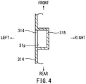
- a ceiling-side vertical wall 315 having a U shape as seen in the plan view is formed to project inward towards the interior of the upper housing 31 such that it surrounds the exhaust hole 31p on three sides, i.e., from the frontward, the rearward and the rightward sides.
- the ceiling-side vertical wall 315 is a vertical wall protruding downward from the ceiling portion 312 of the upper housing 31, and as shown in FIG. 4 , the left edges of the ceiling-side vertical wall 315 are joined to the inner wall surface of the outer circumferencial vertical wall 314 that constitutes the upper housing 31.
- the outer circumferential vertical wall 314 and the ceiling-side vertical wall 315 collectively surround the exhaust hole 31p. Because of this structural configuration, even if water enters the housing 30 from the exhaust hole 31p into the interior of the upper housing 31, upon entry the water contacts the ceiling-side vertical wall 315, and drops down the ceiling-side vertical wall 315 etc. Furthermore, as shown in FIG. 3 , a protruding length of the ceiling-side vertical wall 315 below the ceiling portion 312 of the upper housing 31 in the downward direction is configured such that a lower end position of the ceiling side vertical wall 315 is positioned lower than a lower end position of the exhaust hole 31p in the up-to-down direction.
- a guide wall surface 316 having a recessed arc surface in the cross-sectional view as shown in FIG. 3 is formed along the ceiling-side vertical wall 315, on a corner of the ceiling-side vertical wall 315 and the ceiling portion 312, outside an area surrounded by the ceiling-side vertical wall 315.
- the guide wall surface 316 prevents air flowing in the housing 30 toward the exhaust hole 31p along the ceiling portion 312 from remaining stuck in the upper left corner at the intersection of the ceiling portion 312 and the ceiling-side vertical wall 315.
- the ceiling-side vertical wall 315 surrounding the exhaust hole 31p is referred to as a third vertical wall.
- the lower housing 32 is an open-top-type case in which the electrical components of the charger 10 such as the electrical circuit board 20, the transformer 12t and the diode 12d of the power circuit 12, the microcomputer 14, and the cooling fan 18 etc. are housed. As shown in FIG. 3 , the lower housing 32 is joined to the upper housing 31 by aligning and screw-fastening an upper joining portion 32u of the lower housing 32 with a lower joining portion 31d of the upper housing 31. As shown in FIGS.
- an intake hole 32e for allowing outside air to flow into the interior of the housing 30 is formed on a lower right side of the periphery of the lower housing 32, i.e., on a right corner at the intersection of a bottom plate 323 of the lower housing 32 and the outer circumferential vertical wall 324, approximately at the center of the lower housing 32 in the front-to-rear direction.
- a right-side vertical wall 321 having a U shape as shown in the plan view of FIG. 5 is provided inside the lower housing 32 such that it surrounds the intake hole 32e in a fence-shaped manner on three sides, i.e. in the frontward, the rearward and the leftward sides.
- the right-side vertical wall 321 is a vertical wall that is provided on the bottom plate 323 of the lower housing 32, and the right edges of the right-side vertical wall 321 are joined to the inner peripheral wall surface of the outer circumferential vertical wall 324 that constitutes the lower housing 32.
- the outer circumferential vertical wall 324 and the right-side vertical wall 321 collectively surround the intake hole 32e.
- An upper side of the outer circumferential vertical wall 324 and the right-side vertical wall 321 is open for allowing air to flow through. Because of this structural configuration, water that may enter the lower housing 32 from the intake hole 32e into the interior of the lower housing 32 is blocked from penetrating further by the right-side vertical wall 321.
- the height of the right-side vertical wall 321 is configured such that an upper end position of the right-side vertical wall 321 is higher than an upper end position of the intake hole 32e.
- the right-side vertical wall 321 is referred to as a first vertical wall that surrounds the intake hole 32e.
- a left-side vertical wall 325 is provided on a lower left side of the lower housing 32.
- the left-side vertical wall 325 is formed so as to have a U shape as shown in the plan view of FIG. 5 , and is formed to surround a region exposed to water (refer to the two-dot chain line shown at the left end part of FIG. 5 ), which may enter the upper housing 31 from the exhaust hole 31p and ma drop down the ceiling-side vertical wall 315.
- the left-side vertical wall 325 surrounds said region from the frontward, the rearward and the rightward directions.
- the left-side vertical wall 325 is provided on the bottom plate 323 of the lower housing 32 and the left edges of the left-side vertical wall 325 are joined to the inner wall surface of the outer circumferential vertical wall 324 that constitutes the lower housing 32. Furthermore, a drain hole 323h is formed on the bottom plate 323 at the center of a region surrounded by the outer circumferential vertical wall 324 and the left-side vertical wall 325.
- water which may enter from the exhaust hole 31p into the interior of the upper housing 31 and may drop down the ceiling side vertical wall 315 etc., may drop on the bottom plate 323 that is collectively surrounded by the left-side vertical wall 325 of the lower housing 32 and the outer circumferential vertical wall 324. Then, the water may be discharged from the drain hole 323h.
- the height of the left-side vertical wall 325 is configured to be larger than that of the right-side vertical wall 321. Furthermore, the height of the left-side vertical wall 325 is determined relative to a positional relationship between a lower end of the ceiling side vertical wall 315 and the left-side vertical wall 325.
- the height of the left-side vertical wall 325 is determined such that any water that may drop from the ceiling-side vertical wall 315 would never fail to drop within an area surrounded by the left-side vertical wall 325 and also such that airflow in the housing 30 (refer to the black directional arrows) is not blocked.
- the lower terminal end of the ceiling-side vertical wall 315 is configured to be lower than the upper terminal end of the left-side vertical wall 325 in the up-to-down direction. However, this configuration may block the airflow and in the said case, eventually cooling efficiency of the charger 10 may decrease.
- an upper end of the left-side vertical wall 325 is positioned to be slightly lower than a lower end of the ceiling-side vertical wall 315 such that the former is close to the latter as much as possible in the up-to-down direction.
- the left-side vertical wall 325 is referred to as a second vertical wall that surrounds a region exposed to water that drops from the exhaust hole 31p.
- the electrical circuit board 20 is housed in the lower housing 32 outward of both a region surrounded by the left-side vertical wall 325 as well as a region surrounded by the right-side vertical wall 321.
- the electrical circuit board 20 is placed parallel to the bottom plate 323 of the lower housing 32 by the end edges of the electrical circuit board 20, which are supported from below by a plurality of support legs 25.
- the upper end of the right-side vertical wall 321 is configured to be higher than the upper end of the intake hole 32e in the up-to-down direction.
- the electrical circuit board 20 is configured to be positioned to be lower than the upper end of the left-side vertical wall 325 as well as the upper end of the right-side vertical wall 321 in the up-to-down direction.
- the cooling fan 18 is positioned on the electrical circuit board 20 such that the axis about which the fan rotates is approximately horizontally in the left-to-right direction.
- the cooling fan 18 is positioned in the vicinity of the right-side vertical wall 321 such that an intake side 18e of the cooling fan 18 is directed to the intake hole 32e of the lower housing 32.
- a blowing side 18w of the cooling fan 18 is directed to the electrical components such as the transformer 12t, the diode 12d etc.
- step S101 the cooling fan 18 is held in a stopped state (step S101).
- step S102 the sensed temperature of the electrical components in the charger 10 is compared to a threshold value 1, wherein the sensed temperature of the electrical components is the temperature of the transformer 12t or the diode 12d measured by the thermistor 17. Furthermore, the threshold value 1 is set to, for example, approximately 50° .
- step S102 if the temperature of the electrical components is lower than threshold value 1 (NO in step S102), then the temperature of the electrical components is compared to a second threshold value 2 in step S108.
- the threshold value 2 is lower than the threshold value 1 and set to, for example, approximately 40° .
- step S110 whether or not the battery 50 is connected to the charger 10 is judged in step S110.
- the connection of the battery 50 is judged by detecting a voltage from the voltage detection circuit 15 by the microcomputer 14 of the charger 10 or alternatively by whether or not data from the other microcomputer 52 of the battery 50 is received.
- the procedure returns to step S102.
- the temperature of the electrical components exceeds the threshold value 1 (YES in step S102)
- power is supplied to the cooling fan 18 and the cooling fan 18 is driven (step S103).
- step S104 whether or not the microcomputer 14 receives a fan lock signal is judged in step S104.
- the fan lock signal is a signal that is transmitted from the cooling fan 18 to the microcomputer 14 when the cooling fan 18 breaks down.
- the microcomputer 14 receives the fan lock signal (yes in step S104)
- the cooling fan is stopped.
- the microcomputer 14 sets a maximum charge current value (allowed maximum current value) that can be outputted to charge the battery 50 to prevent overheating.
- step S104 When the microcomputer 14 does not receive the fan lock signal (NO in step S104), i.e., the operation of the cooling fan 18 is proceeding as normal, operation of the cooling fan 18 continues and the limitation of the allowed maximum current value is removed. Because of this setting, the charger 10 can supply a necessary charge current to the battery 50 when connected to the battery 50.
- the cooling fan 18 When the cooling fan 18 is driven in this way, outside air is taken from the intake hole 32e of the housing 30 (lower housing 32) of the charger 10 into the interior of the housing 30. Then, the electrical components such as the transformer 12t and the diode 12d etc. on the electrical circuit board 20 are cooled by the airflow supplied from the cooling fan 18.
- Air that is warmed after cooling the electrical components flows along the ceiling portion 312, and is guided to the lower side of the ceiling-side vertical wall 315 by the recessed guide wall surface 316, in a direction to the exhaust hole 31p. Then, in this manner, the air may pass from the lower side of the inner peripheral surface of the ceiling-side vertical wall 315 and may be discharged from the exhaust hole 31p to the outside of the housing 30.
- step S110 of FIG. 6 a connection state of the battery 50 with respect to the charger 10 is checked in step S110 of FIG. 6 .
- the procedures from step S102 to step S110 are repeatedly executed.
- step S112 whether or not a charge permission signal is input from the battery 50 is judged.
- the charge permission signal is not input (NO in step S112)
- the procedures from step S102 to step S112 are repeatedly executed.
- the cooling fan 18 is driven (step S113). In this case, even if the temperature of the electrical components such as the transformer 12t or the diode 12d etc. is lower than the threshold value 1 and the threshold value 2, the cooling fan 18 is still driven. This is because the charging always increases the temperature of these electrical components.
- step S114 whether or not the fan lock signal is received is judged in step S114. If the fan lock signal is received (YES in step S114), then the cooling fan 18 is stopped. Then, after the maximum charge current value (allowed maximum current value) is set (step S115), the battery 50 is charged (step S116). When the fan lock signal is not received (NO in step S114), the cooling fan 18 continues to run and the battery 50 is charged without setting an allowed maximum current value (step S116). In a case where the battery is not removed from the charger 10 while the battery 50 is being charged (YES in step S117 and NO in step S118), the procedures from step S114 to step S118 are repeatedly executed.
- step S118 When the charging of the battery 50 is completed (YES in step S118), the charging is stopped and the procedure returns to step S102 (step S119).
- step S118 When the battery 50 is removed from the charger 10 while the battery 50 is being charged (NO in step S117), the charging is stopped and the procedure returns to step S102 (step S119).
- the intake hole 32e is surrounded by the right-side vertical wall 321 (first vertical wall) in the interior of the housing 30. Because of this configuration, water that may enter from the intake hole 32e into the interior of the housing 30 is blocked from penetrating further inward by the right-side vertical wall 321 etc.
- the exhaust hole 31p is surrounded by the ceiling-side vertical wall 315 (third vertical wall) in the interior of the housing 30.
- the left-side vertical wall (second vertical wall) that surrounds an area where water drops down the ceiling-side vertical wall 315 is formed on the bottom plate 323 of the housing 30.
- water that may enter from the exhaust hole 31p into the interior of the housing 30 drops down from the ceiling-side vertical wall 315 etc. in the downward direction and is guided to the area surrounded by the left-side vertical wall 325.
- the electrical circuit board 20 is disposed outward of both the area surrounded by the left-side vertical wall 325 as well as the area surrounded by the right-side vertical wall 321 etc. Because of this configuration, when water enters from the intake hole 32e and from the exhaust hole 31p into the interior of the housing 30, it is prevented from reaching the electrical circuit board 20 and the electrical components housed therein.
- the intake hole 32e is formed on the lower portion of the housing 30 so that its upper end is disposed slightly lower than the upper end of the right-side vertical wall 321 (first vertical wall) in the up-to-down direction, and thus water that may enter from the exterior of the charger 10 through the intake hole 32e into the interior of the housing 30 may be prevented from reaching the electrical circuit board 20. Furthermore, since the exhaust hole 31p is formed on the upper portion of the housing 30, proximate to the ceiling portion 312 of the housing 30 and its surroundings, the air that is warmed after cooling the electrical components can be efficiently discharged. Furthermore, the intake hole 32e is formed on the right side of the housing 30 and the exhaust hole 31p is formed on the left side of the housing 30. As a result, the air from the intake hole 32e flows approximately the entire surface area of the housing 30 before being discharged from the exhaust hole 31p.
- the drain hole 323h is formed so as to be surrounded by the left-side vertical wall 325 etc. (second vertical wall) on the bottom plate 323 of the housing 30. Because of this configuration, water, which may enter from the exhaust hole 31p into the interior of the housing 30 and which may then drop down the ceiling-side vertical wall 315 etc. (third vertical wall) and then remains in the area surrounded by the left-side vertical wall 325 etc., can be efficiently discharged through the drain hole 323h.
- the cooling fan 18 is disposed in the vicinity of the right-side vertical wall etc.
- the cooling fan 18 can efficiently take in the outside air from the intake hole 32e to the interior of the housing 30. Furthermore, the air flows along the electrical circuit board 20 in the housing 30 due to the cooling fan 18, and thus the electrical components on the electrical circuit board 20 can be efficiently cooled.
- the guide wall 316 which guides the air flowing along the ceiling portion 312 of the housing 30 to the area surrounded by the ceiling-side vertical wall 315 etc., is formed outward of the region surrounded by the ceiling-side vertical wall 315 etc. that surrounds the exhaust hole 31p. Because of this configuration, the air does not remain at the upper left corner of the inner peripheral boundary of the ceiling-side vertical wall 315 etc. and of the ceiling surface of the housing 30. Furthermore, a protruding length of the ceiling-side vertical wall 315 is set such that the protruding end of the ceiling-side vertical wall 315 below the ceiling portion 312 of the housing 30 is lower than the lower end of the exhaust hole 31p. Because of this configuration, even if water enters from the exhaust hole 31p, the water is blocked by the ceiling-side vertical wall 315 and does not reach outward of the region surrounded by the ceiling-side vertical wall 315.
- the embodiment of the present invention has been explained referring to the above configurations, but it is apparent for a person with ordinary skill in the art that manifold alterations, improvements and modifications can be made without departing from the aim of the present invention. Therefore, the embodiment of the present invention can contain all alterations, improvements and modifications that do not depart from the spirit and aim of the appended claims.
- the embodiment of the present invention can be modified in the following way without limiting to a specified configuration.
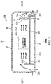
- the present embodiment has provided the example in which the cooling fan 18 is disposed in the vicinity of the intake hole 32e of the housing 30. However, as shown in FIG. 7 , it is possible that the cooling fan 18 is disposed in the vicinity of the exhaust hole 31p (modification 1).
- a left-side vertical wall 325s (second vertical wall), which is provided on the left side of the bottom plate 323 of the lower housing 32, extends to nearly the exhaust hole 31p in the upward direction and a stand 325d on which the cooling fan 18 is placed is formed on an upper inwardly-directed portion of the left-side vertical wall 325. Furthermore, the circumference of the stand 325d of the left-side vertical wall 325 is surrounded by an inclined vertical wall 325s. The cooling fan 18 is placed on the stand 325d of the left-side vertical wall 325 such that the blowing side 18w is directed to the exhaust hole 31p.
- the inclined vertical wall 325s provided around the stand 325d is inclined, a space is formed between the intake side 18e of the cooling fan 18 and the inclined vertical wall 325s, and accordingly due to said space being formed air intake is adequate and not blocked. Furthermore, the ceiling-side vertical wall 315 protruding below the ceiling portion 312 of the upper housing 31 in the downward direction supports the upper side surface of the blowing side 18w of the cooling fan 18, and the protruding length is set so as not to hinder the airflow of the wind caused by the cooling fan 18.
- the ceiling-side vertical wall 315 protruding below the ceiling portion 312 in the downward direction is simply referred to as the third vertical wall.
- the airflow is formed such that the outside air taken from the intake hole 32e is passed through the interior of the housing 30 and is discharged from the exhaust hole 31p due to the driving of the cooling fan 18.
- the electrical components in the housing 30 are cooled by this airflow.
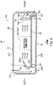
- the intake hole 32e for channeling flow of outside air into the interior of the housing 30 is formed on the lower left side of the lower housing 32.
- the left-side vertical wall 325 that surrounds the intake hole 32e from the frontward, rearward and rightward sides in a fence-shaped manner is provided on the bottom plate 323 of the lower housing 32. Because of this, the left-side vertical wall 325 may be referred to as the first vertical wall.
- an exhaust hole 32p for discharging warmed air in the housing 32 is provided on the lower right side of the lower housing 32.
- the right-side vertical wall 321 that surrounds the exhaust hole 32p from the forward, rearward and leftward sides in a fence-shaped manner is provided on the bottom plate 323 of the lower housing 32. Because of this, the right-side vertical wall may be referred to as the second vertical wall.
- the electrical circuit board 20 is housed in the lower housing 32 outward of both the region surrounded by the left-side vertical wall 325 and the region surrounded by the right-side vertical wall 321.
- the cooling fan 18 is disposed on the electrical circuit board 20 in the vicinity of the right-side vertical wall 321, i.e. in the vicinity of the exhaust hole 32p.
- the cooling fan 18 is positioned such that the blowing side 18w of the cooling fan 18 is directed to the exhaust hole 32p. Because of this configuration, when the cooling fan 18 is driven, the outside air flows from the intake hole 32e of the lower portion of the housing 30, as shown in FIG. 8 .
- the electrical components on the electrical circuit board 20 are cooled by the outside air, and the air warmed by the cooling of the electrical components is discharged from the exhaust hole 32p to the outside of the housing 30.
- the intake hole 32e of the charger 10b according to the modification 2 is formed on the ceiling portion 312 of the upper housing 31.
- an intake hole 31e is formed on the ceiling portion 312 of the upper housing 31, and thus the left-side vertical wall 325 of the lower housing 32 is configured to receive water that drops down from the intake hole 31e.
- the left-side vertical wall 325 of the lower housing 32 is configured to be open expanding in the upward direction in a funnel-shaped manner such that a region exposed to water that drops down from the intake hole 31e is surrounded by a vertical wall upper end 325u of the left-side vertical wall 325.
- the drain hole 323h is formed on the bottom plate 323 of the lower housing 32 in the region surrounded by the left-side vertical wall 325. Because of this configuration, water that drops down from the intake hole 31e of the upper housing 31 is guided to the region surrounded by the left-side wall 325 of the lower housing 32 and discharged from the drain hole 323h.
- the intake hole 32e of the charger 10b according to the modification 2 is formed on the ceiling portion 312 of the upper housing 31.
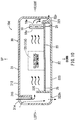
- the ceiling-side vertical wall 315 (third vertical wall) is provided so as to surround the intake hole 31e on the ceiling portion 312 of the charger 10d (upper housing 31) according to the modification 4. Because of this configuration, water that enters from the intake hole 31e to the interior of the housing 30 drops down along the ceiling-side vertical wall 315 etc.
- the left-side vertical wall 325 which surrounds the region exposed to water that drops down along the ceiling-side vertical wall 315 of the upper housing 31, is provided on the bottom plate 323 of the lower housing 32. Furthermore, the drain hole 323h is formed on the bottom plate 323 of the lower housing 32 in the region surrounded by the left-side vertical wall 325. Because of this configuration, water that may enter from the intake hole 31e of the upper housing 31 and that may drop down along the ceiling-side vertical wall 315 is guided to the region surrounded by the left-side vertical wall 325 of the lower housing 32, and is then discharged from the drain hole 323h. In this way, by providing the ceiling-side vertical wall 315 on the upper housing 31, water that enters from the intake hole 31e to the interior of the housing 30 can be efficiently guided to the region surrounded by the left-side vertical wall 325 of the lower housing 32.
- This embodiment provides the example in which the intake hole 31e and the exhaust hole 32p are formed at one end and at the other end, respectively, in the longitudinal direction of the housing 30.
- the intake hole 31e and the exhaust 32p can be respectively provided, for example, on the center portion of the housing 30 in the upward and downward directions.
- the electrical circuit board 20 cannot be disposed at the center of the housing 30, it is necessary to form the electrical circuit board 20 in a frame-shaped manner.
Landscapes
- Engineering & Computer Science (AREA)
- Microelectronics & Electronic Packaging (AREA)
- Physics & Mathematics (AREA)
- Thermal Sciences (AREA)
- Power Engineering (AREA)
- Cooling Or The Like Of Electrical Apparatus (AREA)
- Charge And Discharge Circuits For Batteries Or The Like (AREA)
- Casings For Electric Apparatus (AREA)
Abstract
Description
- The present invention relates to a charger with a housing including an electrical circuit board and a cooling fan.
- Generally, a battery generates heat when charged. When, due to the heat generation of the battery, the temperature of the battery exceeds a predetermined value, charging efficiency decreases. Because of this, a cooling fan for cooling the battery being charged is provided within the charger. In a charger disclosed in Japanese Laid-Open Patent Publication No.
2013-192282 - In recent years, the capacity of a battery has increased and thus in charging the battery, it is desirable to increase the charge current to the charger so as not to take a long time to charge the battery. However, in the configuration where the cooling fan is used for cooling the battery as well as for cooling the charger, it may be difficult to suppress heat generation of the electrical components of the charger with an increased charge current. Because of this, it is necessary to provide a dedicated cooling fan in the housing of the charger for cooling the electrical components separately from a cooling fan for cooling the battery. In the case where a cooling fan for cooling the electrical components is provided within the charger, it is necessary to provide within the housing of the charger an intake hole for taking in outside air as well as an exhaust hole for exhausting the air for cooling the electrical components. In the case where both the intake hole and the exhaust hole are provided in the housing of the charger, if water that enters from the exhaust hole etc. and reaches the electrical components and the electrical circuit board, there is a risk that the charger may malfunction, which is to be countermeasured.
- The present invention was conceived in order to overcome this known problem, and an object of the present invention is to prevent water, which may enter the charger housing from the exhaust hole or the intake hole of the housing of the charger from reaching the electrical circuit board.
- In a first aspect of the present invention, a charger houses an electrical circuit board and a cooling fan in a housing thereof. An intake hole and an exhaust hole are provided in the housing, where outside air that may flows through into the interior of the housing through the intake hole, may cool the charger, and subsequently said air that cools the interior of the housing may be discharged, said actions occurring when the cooling fan is driven. A first vertical wall that surrounds the intake hole or a region exposed to water that drops down the intake hole in a fence-shaped manner, and a second vertical wall that surrounds the exhaust hole or a region exposed by water that drops down the exhaust hole in a fence-shaped manner, are both provided in a bottom plate of the housing. Furthermore, the electrical circuit board is disposed outward of an area where the first vertical wall surrounds the intake hole or the region exposed to water that drops down the intake hole. The electrical circuit board is also disposed outward of an area where the second vertical wall surrounds the exhaust hole or the region exposed to water that drops down the exhaust hole.
- According to the first aspect of the present invention, the intake hole or the region exposed to water that drops down the intake hole is surrounded by the first vertical wall provided on the bottom plate of the housing. Because of this configuration, water that enters from the intake hole to the interior of the housing or water that drops down the intake hole remains within the region surrounded by the first vertical wall. Furthermore, the exhaust hole or the region exposed to water that drops down the exhaust hole is surrounded by the second vertical wall provided on the bottom plate of the housing. Because of this configuration, water that enters from the exhaust hole to the interior of the housing or water that drops down the exhaust hole remains within the region surrounded by the second vertical wall. The electrical circuit board is disposed outward of the area where the first vertical wall surrounds the intake hole or the region exposed to water that drops down the intake hole, and also disposed outward of the area where the second vertical wall surrounds the exhaust hole or the region exposed to water that drops down the exhaust hole. Because of this configuration, water that enters from the intake hole or the exhaust hole is blocked by the first vertical wall as well as the second vertical wall, respectively, and thus water is prevented from reaching the electrical circuit board and the electrical components on the electrical circuit board.
- In a second aspect of the present invention, the intake hole is formed on a lower portion of the housing and surrounded by the first vertical wall, and the exhaust hole is formed on the lower portion of the housing and surrounded by the second vertical wall. In this way, both the intake hole and the exhaust hole are formed on the lower portion of the housing, and thus water is prevented from entering the intake hole as well as from the exhaust hole into the interior area housing the electrical circuit board.
- In a third aspect of the present invention, when a lower end of the intake hole is higher than an upper end of the first vertical wall in the up-to-down direction, the intake hole is configured to be surrounded by a third vertical wall such that water that enters from the intake hole drops down along the third vertical wall to a region surrounded by the first vertical wall, and when a lower end of the exhaust hole is higher than an upper end of the second vertical wall in the up-to-down direction, the exhaust hole is configured to be surrounded by a third vertical wall such that water that enters from the exhaust hole drops down along the third vertical wall to a region surrounded by the second vertical wall. In this way, by providing the third vertical wall, water that enters from the intake hole of the exhaust hole provided on the upper portion of the housing can be efficiently guided to the region surrounded by the first vertical wall or the region surrounded by the second vertical wall.
- In a fourth aspect of the present invention, the intake hole is formed on a lower portion of the housing and surrounded by the first vertical wall, the exhaust hole is formed on an upper portion of the housing and surrounded by the third vertical wall, and a region exposed by water that drops down the exhaust hole along the third vertical wall is surround by the second vertical wall. In this way, the exhaust hole is formed on the upper portion of the housing, and thus warmed air in the housing can be efficiently discharged to the outside.
- In a fifth aspect of the present invention, the intake hole is formed on an upper portion of the housing and is surrounded by the third vertical wall, the exhaust hole is formed on a lower portion of the housing and surrounded by the second vertical wall, and a region exposed by water that drops down the exhaust hole along the third vertical wall is surrounded by the first vertical wall.
- In a sixth aspect of the present invention, the electrical circuit board is disposed above along the bottom plate of the housing, and when the intake hole is formed on the lower portion of the housing, the intake hole is positioned so as to be lower than the upper end of the first vertical wall in the up-do-down direction, and when the exhaust hole is formed on the lower portion of the housing, the exhaust hole is positioned so as to be lower than the upper end of the second vertical wall in the up-to-down direction. Because of this configuration, the electrical circuit board is prevented from being exposed to water that enters the interior of the charger from either the intake hole or the exhaust hole.
- In a seventh aspect of the present invention, the intake hole is formed on one end side of the housing in a plan view and the exhaust hole is formed on the other end side of the housing in the plan view. Because of this configuration, air that is taken from the intake hole flows approximately through the entire surface area within the housing and is then discharged from the exhaust hole to the outside.
- In a eighth aspect of the present invention, a drain hole is formed on the bottom part of the housing in a region surrounded by the first vertical wall or the second vertical wall that is configured to receive water that drops down the intake hole or the exhaust hole. Because of this configuration, water, which enters from the intake hole or the exhaust hole of the upper portion of the housing to the interior of the housing, drops and remains within the region surrounded by the first vertical wall or the second vertical wall, can be efficiently discharged by the drain hole.
- In a ninth aspect of the present invention, the cooling fan is disposed in the vicinity of the first vertical wall or the second vertical wall such that an axis about which the cooling fan rotates is approximately horizontal in the left-to-right direction, and an intake side of the cooling fan is directed to the intake hole as seen in a plan view. Because of this configuration, the cooling fan can efficiently suck outside air from the intake hole. In addition, the cooling fan can flow the air along the electrical circuit board in the housing, and thus the electrical components on the electrical circuit board can be efficiently cooled.
- In a tenth aspect of the present invention, the cooling fan is disposed such that a lower end of the cooling fan is retained approximately as high as the electrical circuit board or below the electrical circuit board. Because of this configuration, the cooling fan can flow the air to a lower area of the housing.
- In an eleventh aspect of the present invention, the third vertical wall that surrounds the intake hole or the exhaust hole is formed on a ceiling portion of the housing, and a guide wall is formed outward of a region surrounded by the third vertical wall such that the guide wall guides airflow between a region surrounded by the third vertical wall and the ceiling portion of the housing. Because of this configuration, air does not remain stuck at an inner peripheral corner at the intersection of the outward of the region surrounded by the third vertical wall and the ceiling surface of the housing.
- In a twelfth aspect of the present invention, the third vertical wall that surrounds the intake hole or the exhaust hole is formed on a ceiling portion of the housing, and a protruding length of the third vertical wall is configured such that an protruding end of the third vertical wall below the ceiling portion of the housing is lower than a lower end of the intake hole or the exhaust hole in the up-to-down direction. Because of this configuration, when water enters from the intake hole or the exhaust hole, the water is blocked by the third vertical wall and is prevented from reaching outward of the region surrounded by the third vertical wall.
-
-
FIG. 1 is a wiring block diagram showing a connection state between a battery and a charger according to anembodiment 1 of the present invention. -
FIG. 2 is a schematic circuit diagram showing an electric power circuit of the charger. -
FIG. 3 is a schematic longitudinal sectional view showing an interior of a housing of the charger. -
FIG. 4 is a plan sectional view showing an exhaust hole of an upper housing and a vertical wall on a ceiling side (a third vertical wall). -
FIG. 5 is a schematic plan view showing an entirety of a lower housing and an electrical circuit board. -
FIG. 6 is a flowchart showing an operation of the charger. -
FIG. 7 is a schematic longitudinal sectional view showing an interior of a housing of the charger according to a modified example 1. -
FIG. 8 is a schematic longitudinal sectional view showing an interior of a housing of the charger according to a modified example 2. -
FIG. 9 is a schematic longitudinal sectional view showing an interior of a housing of the charger according to a modified example 3. -
FIG. 10 is a schematic longitudinal sectional view showing an interior of a housing of the charger according to a modified example 4. - A charger according to an
embodiment 1 of the present invention will be described below with reference toFIGS. 1 to 10 . Acharger 10 according to the present invention is a charger for charging abattery 50 used for an electric power tool. The front, rear, left, right, up and down directions shown in the figures correspond to the front, rear, left, right, up and down directions relative to thecharger 10. - As shown in
FIG. 1 depicting a wiring block diagram, thecharger 10 comprises anelectric power circuit 12, amicrocomputer 14, a coolingfan 18 and avoltage detection circuit 15 etc. As shown inFIG. 2 , theelectric power circuit 12 is an electric circuit including a DC power source (Vp) for charge as well as a DC power source (Vcd, Vcc) for control by converting AC power from a domestic AC power source (power source input, e.g. mains) to DC power. The DC power source (Vp) for charge in theelectric power circuit 12 is a power source used for charging the battery 50 (refer toFIG. 1 ). As shown inFIG. 2 , a power voltage is lowered to a predetermined voltage by atransformer 12t, and then the lowered voltage is converted to a DC voltage by adiode 12d. A thermistor 17 (refer toFIG. 1 ) for detecting the temperature of thetransformer 12t or thediode 12d is mounted on the correspondingtransformer 12t ordiode 12d, respectively. - As shown in
FIG. 2 , switching elements FET1 and FET2 are provided as part of a power sourcepositive line 21p of the DC power source for charge (Vp), and the power sourcepositive line 21p is in turn connected to a positive terminal Ps of thecharger 10. Furthermore, a power sourcenegative line 21n of the DC power source for charge (Vp) is connected to a negative terminal Ns of thecharger 10, while at the same time it is also connected at a different location alongline 21n to an earth terminal E as a ground connection. As shown inFIG. 1 , the positive terminal Ps and the negative terminal Ns of thecharger 10 are connected to corresponding positive terminal Pb and negative terminal Nb of thebattery 50, respectively, when thebattery 50 is connected to thecharger 10. Furthermore, the difference in voltage between the positive terminal Ps and the negative terminal Ns of thecharger 10 is configured to be detected by avoltage detection circuit 15. - The DC power source (Vcd) for control in the
electric power circuit 12 is a DC 12V source used for operating the coolingfan 18 etc, and wherein the source is formed by converting AC power of the AC power source to DC power by aconverter 12c. The coolingfan 18 is a fan for cooling theelectric power circuit 12 when the temperature of thetransformer 12t or thediode 12d of theelectric power circuit 12 as detected by thethermistor 17 increases above a predetermined value while thebattery 50 is being charged. In the figures, a fan for cooling thebattery 50 is omitted. Another DC power source (Vcc) for control in theelectric power circuit 12 is a DC 5V source which may be used for operating themicrocomputer 14 etc., wherein the source is formed by lowering the output voltage (12V) of theconverter 12c by using avoltage regulator 12r. - The
microcomputer 14 is a control part which runs control routines for a charge control of thebattery 50 based on sensed information from thebattery 50 that is connected to thecharger 10, and furthermore the microcomputer 13 is configured to switch on/off of the switching elements FET1 and FET2 in the electric power circuit 12 (DC power source (Vp) for charge). For this operation, as shown inFIG. 1 , when thebattery 50 is connected to thecharger 10, themicrocomputer 14 is connected to anothermicrocomputer 52 of thebattery 50 via a digital communication terminal COM, an analog signal terminal TM and via a microcomputer power terminal Vcc. - Furthermore, the
microcomputer 14 is configured to process the voltage signal from thevoltage detection circuit 15 as an input. Because of this connection, themicrocomputer 14 can detect an output voltage of thebattery 50 when thebattery 50 is connected to thecharger 10. Furthermore, via the output voltage, themicrocomputer 14 can also detect whether thebattery 50 is connected to thecharger 10. Furthermore, themicrocomputer 14 is also configured to process the temperature signal from thethermistor 17 as well as a fan lock signal (failure signal) from the coolingfan 18 as input. In addition, themicrocomputer 14 is also configured to drive the coolingfan 18 based on the temperature signal of thethermistor 17 etc. Furthermore, themicrocomputer 14 is also configured to output signals relating to a charging state, a temperature state and a driving state of the coolingfan 18 to areporting section 16. - As shown in
FIG. 3 , thehousing 30 of thecharger 10 comprises anupper housing 31 and alower housing 32, each of which has an approximately rectangular shape as seen from a side view. Theupper housing 31 is a lid-shaped case that covers the electric components mounted on the upper surface of thelower housing 32 from above. A connection portion (not shown in the figures) that connects to thebattery 50 is formed on the outer peripheral upper surface of theupper housing 31. Furthermore, the positive terminal Ps, the negative terminal Ns, the digital communication terminal COM, the analog signal terminal TM and the microcomputer power terminal Vcc are also provided on the connection portion of theupper housing 31. - As shown in
FIGS. 3 and4 , anexhaust hole 31p for discharging air within the interior of thehousing 30 is formed on the upper left portion of the periphery of theupper housing 31, i.e., on an upper left corner at the intersection of aceiling portion 312 of theupper housing 31 and an outer circumferencialvertical wall 314, approximately at the center of theupper housing 31 in the front-to-rear direction. Furthermore, a ceiling-sidevertical wall 315 having a U shape as seen in the plan view is formed to project inward towards the interior of theupper housing 31 such that it surrounds theexhaust hole 31p on three sides, i.e., from the frontward, the rearward and the rightward sides. The ceiling-sidevertical wall 315 is a vertical wall protruding downward from theceiling portion 312 of theupper housing 31, and as shown inFIG. 4 , the left edges of the ceiling-sidevertical wall 315 are joined to the inner wall surface of the outer circumferencialvertical wall 314 that constitutes theupper housing 31. - In other words, as shown in
FIG. 4 , the outer circumferentialvertical wall 314 and the ceiling-sidevertical wall 315 collectively surround theexhaust hole 31p. Because of this structural configuration, even if water enters thehousing 30 from theexhaust hole 31p into the interior of theupper housing 31, upon entry the water contacts the ceiling-sidevertical wall 315, and drops down the ceiling-sidevertical wall 315 etc. Furthermore, as shown inFIG. 3 , a protruding length of the ceiling-sidevertical wall 315 below theceiling portion 312 of theupper housing 31 in the downward direction is configured such that a lower end position of the ceiling sidevertical wall 315 is positioned lower than a lower end position of theexhaust hole 31p in the up-to-down direction. - Furthermore, a
guide wall surface 316 having a recessed arc surface in the cross-sectional view as shown inFIG. 3 is formed along the ceiling-sidevertical wall 315, on a corner of the ceiling-sidevertical wall 315 and theceiling portion 312, outside an area surrounded by the ceiling-sidevertical wall 315. Theguide wall surface 316 prevents air flowing in thehousing 30 toward theexhaust hole 31p along theceiling portion 312 from remaining stuck in the upper left corner at the intersection of theceiling portion 312 and the ceiling-sidevertical wall 315. The ceiling-sidevertical wall 315 surrounding theexhaust hole 31p is referred to as a third vertical wall. - The
lower housing 32 is an open-top-type case in which the electrical components of thecharger 10 such as theelectrical circuit board 20, thetransformer 12t and thediode 12d of thepower circuit 12, themicrocomputer 14, and the coolingfan 18 etc. are housed. As shown inFIG. 3 , thelower housing 32 is joined to theupper housing 31 by aligning and screw-fastening an upper joiningportion 32u of thelower housing 32 with a lower joiningportion 31d of theupper housing 31. As shown inFIGS. 3 and5 , anintake hole 32e for allowing outside air to flow into the interior of thehousing 30 is formed on a lower right side of the periphery of thelower housing 32, i.e., on a right corner at the intersection of abottom plate 323 of thelower housing 32 and the outer circumferentialvertical wall 324, approximately at the center of thelower housing 32 in the front-to-rear direction. - Furthermore, a right-side
vertical wall 321 having a U shape as shown in the plan view ofFIG. 5 is provided inside thelower housing 32 such that it surrounds theintake hole 32e in a fence-shaped manner on three sides, i.e. in the frontward, the rearward and the leftward sides. The right-sidevertical wall 321 is a vertical wall that is provided on thebottom plate 323 of thelower housing 32, and the right edges of the right-sidevertical wall 321 are joined to the inner peripheral wall surface of the outer circumferentialvertical wall 324 that constitutes thelower housing 32. In other words, as shown inFIG. 5 , the outer circumferentialvertical wall 324 and the right-sidevertical wall 321 collectively surround theintake hole 32e. An upper side of the outer circumferentialvertical wall 324 and the right-sidevertical wall 321 is open for allowing air to flow through. Because of this structural configuration, water that may enter thelower housing 32 from theintake hole 32e into the interior of thelower housing 32 is blocked from penetrating further by the right-sidevertical wall 321. The height of the right-sidevertical wall 321 is configured such that an upper end position of the right-sidevertical wall 321 is higher than an upper end position of theintake hole 32e. The right-sidevertical wall 321 is referred to as a first vertical wall that surrounds theintake hole 32e. - As shown in
FIGS. 3 and5 , a left-sidevertical wall 325 is provided on a lower left side of thelower housing 32. The left-sidevertical wall 325 is formed so as to have a U shape as shown in the plan view ofFIG. 5 , and is formed to surround a region exposed to water (refer to the two-dot chain line shown at the left end part ofFIG. 5 ), which may enter theupper housing 31 from theexhaust hole 31p and ma drop down the ceiling-sidevertical wall 315. The left-sidevertical wall 325 surrounds said region from the frontward, the rearward and the rightward directions. The left-sidevertical wall 325 is provided on thebottom plate 323 of thelower housing 32 and the left edges of the left-sidevertical wall 325 are joined to the inner wall surface of the outer circumferentialvertical wall 324 that constitutes thelower housing 32. Furthermore, adrain hole 323h is formed on thebottom plate 323 at the center of a region surrounded by the outer circumferentialvertical wall 324 and the left-sidevertical wall 325. - Because of this configuration, water, which may enter from the
exhaust hole 31p into the interior of theupper housing 31 and may drop down the ceiling sidevertical wall 315 etc., may drop on thebottom plate 323 that is collectively surrounded by the left-sidevertical wall 325 of thelower housing 32 and the outer circumferentialvertical wall 324. Then, the water may be discharged from thedrain hole 323h. The height of the left-sidevertical wall 325 is configured to be larger than that of the right-sidevertical wall 321. Furthermore, the height of the left-sidevertical wall 325 is determined relative to a positional relationship between a lower end of the ceiling sidevertical wall 315 and the left-sidevertical wall 325. That is, the height of the left-sidevertical wall 325 is determined such that any water that may drop from the ceiling-sidevertical wall 315 would never fail to drop within an area surrounded by the left-sidevertical wall 325 and also such that airflow in the housing 30 (refer to the black directional arrows) is not blocked. For the water from the ceiling-sidevertical wall 315 to drop within the area surrounded by the left-sidevertical wall 325 without fail, it is preferable that the lower terminal end of the ceiling-sidevertical wall 315 is configured to be lower than the upper terminal end of the left-sidevertical wall 325 in the up-to-down direction. However, this configuration may block the airflow and in the said case, eventually cooling efficiency of thecharger 10 may decrease. Even in the case where the lower terminal end of the ceiling-sidevertical wall 315 is lower than the upper terminal end of the left-sidevertical wall 325, if a distance between the ceiling-sidevertical wall 315 and the left-sidevertical wall 325 is large enough, an airflow passage can be obtained. However, a larger distance between the ceiling-sidevertical wall 315 and the left-sidevertical wall 325 would cause another problem of increasing a dimension of thecharger 10. Because of these constraints, in order to accomplish adequate waterproof performance as well as adequate cooling performance, an upper end of the left-sidevertical wall 325 is positioned to be slightly lower than a lower end of the ceiling-sidevertical wall 315 such that the former is close to the latter as much as possible in the up-to-down direction. The left-sidevertical wall 325 is referred to as a second vertical wall that surrounds a region exposed to water that drops from theexhaust hole 31p. - As shown in
FIG. 5 , theelectrical circuit board 20 is housed in thelower housing 32 outward of both a region surrounded by the left-sidevertical wall 325 as well as a region surrounded by the right-sidevertical wall 321. As shown inFIG. 3 , theelectrical circuit board 20 is placed parallel to thebottom plate 323 of thelower housing 32 by the end edges of theelectrical circuit board 20, which are supported from below by a plurality ofsupport legs 25. The upper end of the right-sidevertical wall 321 is configured to be higher than the upper end of theintake hole 32e in the up-to-down direction. Furthermore, theelectrical circuit board 20 is configured to be positioned to be lower than the upper end of the left-sidevertical wall 325 as well as the upper end of the right-sidevertical wall 321 in the up-to-down direction. - Electrical components of the
charger 10 such as thetransformer 12t, thediode 12d, themicrocomputer 14, and the coolingfan 18 etc. are mounted on theelectrical circuit board 20. As shown inFIGS. 3 and5 , the coolingfan 18 is positioned on theelectrical circuit board 20 such that the axis about which the fan rotates is approximately horizontally in the left-to-right direction. The coolingfan 18 is positioned in the vicinity of the right-sidevertical wall 321 such that anintake side 18e of the coolingfan 18 is directed to theintake hole 32e of thelower housing 32. Furthermore, a blowingside 18w of the coolingfan 18 is directed to the electrical components such as thetransformer 12t, thediode 12d etc. - Next, operation of the
charger 10 is described according to the flowchart shown inFIG. 6 . The procedure as shown in the flowchart ofFIG. 6 is executed by a program stored in the memory of themicrocomputer 14. When power is supplied to thecharger 10, themicrocomputer 14 runs and the program starts. At an initial stage, the coolingfan 18 is held in a stopped state (step S101). Next, in step S102, the sensed temperature of the electrical components in thecharger 10 is compared to athreshold value 1, wherein the sensed temperature of the electrical components is the temperature of thetransformer 12t or thediode 12d measured by thethermistor 17. Furthermore, thethreshold value 1 is set to, for example, approximately 50° . In step S102, if the temperature of the electrical components is lower than threshold value 1 (NO in step S102), then the temperature of the electrical components is compared to asecond threshold value 2 in step S108. Thethreshold value 2 is lower than thethreshold value 1 and set to, for example, approximately 40° . - When the temperature of the electrical components is lower than the threshold value 2 (yes in step S108), the cooling
fan 18 is held in the stopped state (step S109). Next, whether or not thebattery 50 is connected to thecharger 10 is judged in step S110. The connection of thebattery 50 is judged by detecting a voltage from thevoltage detection circuit 15 by themicrocomputer 14 of thecharger 10 or alternatively by whether or not data from theother microcomputer 52 of thebattery 50 is received. When thebattery 50 is not connected to thecharger 10, the procedure returns to step S102. When the temperature of the electrical components exceeds the threshold value 1 (YES in step S102), power is supplied to the coolingfan 18 and the coolingfan 18 is driven (step S103). Next, whether or not themicrocomputer 14 receives a fan lock signal is judged in step S104. - The fan lock signal is a signal that is transmitted from the cooling
fan 18 to themicrocomputer 14 when the coolingfan 18 breaks down. When themicrocomputer 14 receives the fan lock signal (yes in step S104), the cooling fan is stopped. Furthermore, in a state where the coolingfan 18 is stopped, themicrocomputer 14 sets a maximum charge current value (allowed maximum current value) that can be outputted to charge thebattery 50 to prevent overheating. As a result, because of this setting, even in a case where the coolingfan 18 is stopped and while thebattery 50 is being charged, the temperature of the electrical components does not exceed an allowed value due to the reduced value of the current outputted. - When the
microcomputer 14 does not receive the fan lock signal (NO in step S104), i.e., the operation of the coolingfan 18 is proceeding as normal, operation of the coolingfan 18 continues and the limitation of the allowed maximum current value is removed. Because of this setting, thecharger 10 can supply a necessary charge current to thebattery 50 when connected to thebattery 50. When the coolingfan 18 is driven in this way, outside air is taken from theintake hole 32e of the housing 30 (lower housing 32) of thecharger 10 into the interior of thehousing 30. Then, the electrical components such as thetransformer 12t and thediode 12d etc. on theelectrical circuit board 20 are cooled by the airflow supplied from the coolingfan 18. Air that is warmed after cooling the electrical components flows along theceiling portion 312, and is guided to the lower side of the ceiling-sidevertical wall 315 by the recessedguide wall surface 316, in a direction to theexhaust hole 31p. Then, in this manner, the air may pass from the lower side of the inner peripheral surface of the ceiling-sidevertical wall 315 and may be discharged from theexhaust hole 31p to the outside of thehousing 30. - Next, a connection state of the
battery 50 with respect to thecharger 10 is checked in step S110 ofFIG. 6 . When thebattery 50 is not connected to the charger 10 (NO in step S110), the procedures from step S102 to step S110 are repeatedly executed. When thebattery 50 is connected to the charger 10 (YES in step S110), whether or not a charge permission signal is input from thebattery 50 is judged (step S112). When the charge permission signal is not input (NO in step S112), the procedures from step S102 to step S112 are repeatedly executed. When the charge permission signal is input (YES in step S112), the coolingfan 18 is driven (step S113). In this case, even if the temperature of the electrical components such as thetransformer 12t or thediode 12d etc. is lower than thethreshold value 1 and thethreshold value 2, the coolingfan 18 is still driven. This is because the charging always increases the temperature of these electrical components. - Next, whether or not the fan lock signal is received is judged in step S114. If the fan lock signal is received (YES in step S114), then the cooling
fan 18 is stopped. Then, after the maximum charge current value (allowed maximum current value) is set (step S115), thebattery 50 is charged (step S116). When the fan lock signal is not received (NO in step S114), the coolingfan 18 continues to run and thebattery 50 is charged without setting an allowed maximum current value (step S116). In a case where the battery is not removed from thecharger 10 while thebattery 50 is being charged (YES in step S117 and NO in step S118), the procedures from step S114 to step S118 are repeatedly executed. When the charging of thebattery 50 is completed (YES in step S118), the charging is stopped and the procedure returns to step S102 (step S119). When thebattery 50 is removed from thecharger 10 while thebattery 50 is being charged (NO in step S117), the charging is stopped and the procedure returns to step S102 (step S119). - According to the
charger 10 of the present embodiment, theintake hole 32e is surrounded by the right-side vertical wall 321 (first vertical wall) in the interior of thehousing 30. Because of this configuration, water that may enter from theintake hole 32e into the interior of thehousing 30 is blocked from penetrating further inward by the right-sidevertical wall 321 etc. Similarly, theexhaust hole 31p is surrounded by the ceiling-side vertical wall 315 (third vertical wall) in the interior of thehousing 30. Furthermore, the left-side vertical wall (second vertical wall) that surrounds an area where water drops down the ceiling-sidevertical wall 315 is formed on thebottom plate 323 of thehousing 30. Because of this configuration, water that may enter from theexhaust hole 31p into the interior of thehousing 30 drops down from the ceiling-sidevertical wall 315 etc. in the downward direction and is guided to the area surrounded by the left-sidevertical wall 325. Theelectrical circuit board 20 is disposed outward of both the area surrounded by the left-sidevertical wall 325 as well as the area surrounded by the right-sidevertical wall 321 etc. Because of this configuration, when water enters from theintake hole 32e and from theexhaust hole 31p into the interior of thehousing 30, it is prevented from reaching theelectrical circuit board 20 and the electrical components housed therein. - Furthermore, the
intake hole 32e is formed on the lower portion of thehousing 30 so that its upper end is disposed slightly lower than the upper end of the right-side vertical wall 321 (first vertical wall) in the up-to-down direction, and thus water that may enter from the exterior of thecharger 10 through theintake hole 32e into the interior of thehousing 30 may be prevented from reaching theelectrical circuit board 20. Furthermore, since theexhaust hole 31p is formed on the upper portion of thehousing 30, proximate to theceiling portion 312 of thehousing 30 and its surroundings, the air that is warmed after cooling the electrical components can be efficiently discharged. Furthermore, theintake hole 32e is formed on the right side of thehousing 30 and theexhaust hole 31p is formed on the left side of thehousing 30. As a result, the air from theintake hole 32e flows approximately the entire surface area of thehousing 30 before being discharged from theexhaust hole 31p. - Furthermore, the
drain hole 323h is formed so as to be surrounded by the left-sidevertical wall 325 etc. (second vertical wall) on thebottom plate 323 of thehousing 30. Because of this configuration, water, which may enter from theexhaust hole 31p into the interior of thehousing 30 and which may then drop down the ceiling-sidevertical wall 315 etc. (third vertical wall) and then remains in the area surrounded by the left-sidevertical wall 325 etc., can be efficiently discharged through thedrain hole 323h. In addition, the coolingfan 18 is disposed in the vicinity of the right-side vertical wall etc. such that the axis about which the fan rotates is disposed approximately horizontally in the left-to-right direction, and also theintake side 18e of the coolingfan 18 is directed to theintake hole 32e as shown in a plan view. Because of this configuration, the coolingfan 18 can efficiently take in the outside air from theintake hole 32e to the interior of thehousing 30. Furthermore, the air flows along theelectrical circuit board 20 in thehousing 30 due to the coolingfan 18, and thus the electrical components on theelectrical circuit board 20 can be efficiently cooled. - Furthermore, the
guide wall 316, which guides the air flowing along theceiling portion 312 of thehousing 30 to the area surrounded by the ceiling-sidevertical wall 315 etc., is formed outward of the region surrounded by the ceiling-sidevertical wall 315 etc. that surrounds theexhaust hole 31p. Because of this configuration, the air does not remain at the upper left corner of the inner peripheral boundary of the ceiling-sidevertical wall 315 etc. and of the ceiling surface of thehousing 30. Furthermore, a protruding length of the ceiling-sidevertical wall 315 is set such that the protruding end of the ceiling-sidevertical wall 315 below theceiling portion 312 of thehousing 30 is lower than the lower end of theexhaust hole 31p. Because of this configuration, even if water enters from theexhaust hole 31p, the water is blocked by the ceiling-sidevertical wall 315 and does not reach outward of the region surrounded by the ceiling-sidevertical wall 315. - The embodiment of the present invention has been explained referring to the above configurations, but it is apparent for a person with ordinary skill in the art that manifold alterations, improvements and modifications can be made without departing from the aim of the present invention. Therefore, the embodiment of the present invention can contain all alterations, improvements and modifications that do not depart from the spirit and aim of the appended claims. The embodiment of the present invention can be modified in the following way without limiting to a specified configuration. For example, the present embodiment has provided the example in which the cooling
fan 18 is disposed in the vicinity of theintake hole 32e of thehousing 30. However, as shown inFIG. 7 , it is possible that the coolingfan 18 is disposed in the vicinity of theexhaust hole 31p (modification 1). - In a
charger 10a according to themodification 1, a left-sidevertical wall 325s (second vertical wall), which is provided on the left side of thebottom plate 323 of thelower housing 32, extends to nearly theexhaust hole 31p in the upward direction and astand 325d on which the coolingfan 18 is placed is formed on an upper inwardly-directed portion of the left-sidevertical wall 325. Furthermore, the circumference of thestand 325d of the left-sidevertical wall 325 is surrounded by an inclinedvertical wall 325s. The coolingfan 18 is placed on thestand 325d of the left-sidevertical wall 325 such that the blowingside 18w is directed to theexhaust hole 31p. - Because the inclined
vertical wall 325s provided around thestand 325d is inclined, a space is formed between theintake side 18e of the coolingfan 18 and the inclinedvertical wall 325s, and accordingly due to said space being formed air intake is adequate and not blocked. Furthermore, the ceiling-sidevertical wall 315 protruding below theceiling portion 312 of theupper housing 31 in the downward direction supports the upper side surface of the blowingside 18w of the coolingfan 18, and the protruding length is set so as not to hinder the airflow of the wind caused by the coolingfan 18. The ceiling-sidevertical wall 315 protruding below theceiling portion 312 in the downward direction is simply referred to as the third vertical wall. Because of this configuration, when the cooling fan is driven, the airflow is formed such that the outside air taken from theintake hole 32e is passed through the interior of thehousing 30 and is discharged from theexhaust hole 31p due to the driving of the coolingfan 18. The electrical components in thehousing 30 are cooled by this airflow. - As shown in
FIG. 8 , in acharger 10b according to themodification 2, theintake hole 32e for channeling flow of outside air into the interior of thehousing 30 is formed on the lower left side of thelower housing 32. Furthermore, the left-sidevertical wall 325 that surrounds theintake hole 32e from the frontward, rearward and rightward sides in a fence-shaped manner is provided on thebottom plate 323 of thelower housing 32. Because of this, the left-sidevertical wall 325 may be referred to as the first vertical wall. Furthermore, anexhaust hole 32p for discharging warmed air in thehousing 32 is provided on the lower right side of thelower housing 32. Furthermore, the right-sidevertical wall 321 that surrounds theexhaust hole 32p from the forward, rearward and leftward sides in a fence-shaped manner is provided on thebottom plate 323 of thelower housing 32. Because of this, the right-side vertical wall may be referred to as the second vertical wall. - As shown in
FIG. 8 , theelectrical circuit board 20 is housed in thelower housing 32 outward of both the region surrounded by the left-sidevertical wall 325 and the region surrounded by the right-sidevertical wall 321. The coolingfan 18 is disposed on theelectrical circuit board 20 in the vicinity of the right-sidevertical wall 321, i.e. in the vicinity of theexhaust hole 32p. The coolingfan 18 is positioned such that the blowingside 18w of the coolingfan 18 is directed to theexhaust hole 32p. Because of this configuration, when the coolingfan 18 is driven, the outside air flows from theintake hole 32e of the lower portion of thehousing 30, as shown inFIG. 8 . The electrical components on theelectrical circuit board 20 are cooled by the outside air, and the air warmed by the cooling of the electrical components is discharged from theexhaust hole 32p to the outside of thehousing 30. - In this way, in the above discussed
charger 10b, since an opening such as the exhaust hole is not formed on theupper housing 31, water is prevented from entering the interior of thehousing 30. Furthermore, it is not necessary to provide the third vertical wall that guides water, and thus theupper housing 31 can be easily formed. Furthermore, since the lower end of theintake hole 32e as well as the lower end of theexhaust hole 32p is formed on thebottom plate 323 of thelower housing 32, both the lower end of theintake hole 32e and the lower end of theexhaust hole 32p can provide a dual use as drain holes, and thus it is not necessary to form another dedicated drain hole. - As shown in
FIG. 9 , in acharger 10c according to the modification 3, theintake hole 32e of thecharger 10b according to themodification 2 is formed on theceiling portion 312 of theupper housing 31. As shown inFIG. 9 , in the charger 20c according to the modification 3, anintake hole 31e is formed on theceiling portion 312 of theupper housing 31, and thus the left-sidevertical wall 325 of thelower housing 32 is configured to receive water that drops down from theintake hole 31e. In more detail, the left-sidevertical wall 325 of thelower housing 32 is configured to be open expanding in the upward direction in a funnel-shaped manner such that a region exposed to water that drops down from theintake hole 31e is surrounded by a vertical wallupper end 325u of the left-sidevertical wall 325. Because of this configuration, a third vertical wall that surrounds theintake hole 31e can be eliminated. Furthermore, thedrain hole 323h is formed on thebottom plate 323 of thelower housing 32 in the region surrounded by the left-sidevertical wall 325. Because of this configuration, water that drops down from theintake hole 31e of theupper housing 31 is guided to the region surrounded by the left-side wall 325 of thelower housing 32 and discharged from thedrain hole 323h. - As shown in
FIG. 10 , in acharger 10d according to the modification 4, theintake hole 32e of thecharger 10b according to themodification 2 is formed on theceiling portion 312 of theupper housing 31. As shown inFIG. 10 , the ceiling-side vertical wall 315 (third vertical wall) is provided so as to surround theintake hole 31e on theceiling portion 312 of thecharger 10d (upper housing 31) according to the modification 4. Because of this configuration, water that enters from theintake hole 31e to the interior of thehousing 30 drops down along the ceiling-sidevertical wall 315 etc. - As shown in
FIG. 10 , the left-sidevertical wall 325, which surrounds the region exposed to water that drops down along the ceiling-sidevertical wall 315 of theupper housing 31, is provided on thebottom plate 323 of thelower housing 32. Furthermore, thedrain hole 323h is formed on thebottom plate 323 of thelower housing 32 in the region surrounded by the left-sidevertical wall 325. Because of this configuration, water that may enter from theintake hole 31e of theupper housing 31 and that may drop down along the ceiling-sidevertical wall 315 is guided to the region surrounded by the left-sidevertical wall 325 of thelower housing 32, and is then discharged from thedrain hole 323h. In this way, by providing the ceiling-sidevertical wall 315 on theupper housing 31, water that enters from theintake hole 31e to the interior of thehousing 30 can be efficiently guided to the region surrounded by the left-sidevertical wall 325 of thelower housing 32. - This embodiment provides the example in which the
intake hole 31e and theexhaust hole 32p are formed at one end and at the other end, respectively, in the longitudinal direction of thehousing 30. However, theintake hole 31e and theexhaust 32p can be respectively provided, for example, on the center portion of thehousing 30 in the upward and downward directions. In this configuration, because theelectrical circuit board 20 cannot be disposed at the center of thehousing 30, it is necessary to form theelectrical circuit board 20 in a frame-shaped manner.
Claims (12)
- A charger, housing an electrical circuit board and a cooling fan in a housing of the charger, wherein:an intake hole and an exhaust hole are provided in the housing, where outside air is taken from the intake hole and cools the interior of the housing and then is discharged from the exhaust hole when the cooling fan is driven;a first vertical wall that surrounds the intake hole or a region exposed to water that drops down the intake hole in a fence-shaped manner, and a second vertical wall that surrounds the exhaust hole or a region exposed to water that drops down the exhaust hole in the fence-shaped manner are provided on a bottom plate of the housing; andthe electrical circuit board is disposed outward of an area where the first vertical wall surrounds the intake hole or the region exposed to water that drops down the intake hole, further wherein the electrical circuit board is disposed outward of an area where the second vertical wall surrounds the exhaust hole or the region exposed to water that drops down the exhaust hole.
- The charger according to claim 1, wherein:the intake hole is formed on a lower portion of the housing and surrounded by the first vertical wall; andthe exhaust hole is formed on the lower portion of the housing and surrounded by the second vertical wall.
- The charger according to claim 1, wherein:in a case where a lower end of the intake hole is higher than an upper end of the first vertical wall in the up-to-down direction, the intake hole is configured to be surrounded by a third vertical wall such that water that enters from the intake hole drops down along the third vertical wall to a region surrounded by the first vertical wall; andin a case where a lower end of the exhaust hole is higher than an upper end of the second vertical wall in the up-to-down direction, the exhaust hole is configured to be surrounded by a third vertical wall such that water that enters from the exhaust hole drops down along the third vertical wall to a region surrounded by the second vertical wall.
- The charger according to claim 3, wherein:the intake hole is formed on a lower portion of the housing and surrounded by the first vertical wall;the exhaust hole is formed on an upper portion of the housing and surrounded by the third vertical wall; anda region exposed to water that drops down the exhaust hole along the third vertical wall is surround by the second vertical wall.
- The charger according to claim 3, wherein:the intake hole is formed on an upper portion of the housing and surrounded by the third vertical wall;the exhaust hole is formed on a lower portion of the housing and surrounded by the second vertical wall; anda region exposed to water that drops down the exhaust hole along the third vertical wall is surround by the first vertical wall.
- The charger according to any one of claims 1 to 5, wherein:the electrical circuit board is disposed above the bottom plate of the housing along the bottom plate of the housing;in a case where the intake hole is formed on the lower portion of the housing, the intake hole is positioned so as to be lower than the upper end of the first vertical wall in the up-do-down direction; andin a case where the exhaust hole is formed on the lower portion of the housing, the exhaust hole is positioned so as to be lower than the upper end of the second vertical wall in the up-do-down direction.
- The charger according to any one of claims 1 to 6, wherein,
the intake hole is formed on one end side of the housing as seen in a plan view and the exhaust hole is formed on the other end side of the housing as seen in the plan view. - The charger according to any one of claims 1 to 7, wherein,
a drain hole is formed on the bottom part of the housing in a region surrounded by the first vertical wall or the second vertical wall, where the region is configured to receive water that drops down the intake hole or the exhaust hole. - The charger according to any one of claims 1 to 8, wherein:the cooling fan is disposed in the vicinity of the first vertical wall or the second vertical wall such that an axis about which the cooling fan rotates is approximately horizontal; andan intake side of the cooling fan is directed to the intake hole, as seen in a plan view.
- The charger according to claim 9, wherein,
the cooling fan is disposed such that a lower end of the cooling fan is retained approximately as high as or below the electrical circuit board. - The charger according to any one of claims 3 to 10, wherein:the third vertical wall that surrounds the intake hole or the exhaust hole is formed on a ceiling portion of the housing; anda guide wall is formed outward of a region surrounded by the third vertical wall such that the guide wall guides airflow between a region surrounded by the third vertical wall and the ceiling portion of the housing.
- The charger according to any one of claims 3 to 10, wherein:the third vertical wall that surrounds the intake hole or the exhaust hole is formed on a ceiling portion of the housing; anda protruding length of the third vertical wall is configured such that an protruding end of the third vertical wall below the ceiling portion of the housing is lower than a lower end of the respective intake hole or the exhaust hole in the up-to-down direction.
Applications Claiming Priority (2)
| Application Number | Priority Date | Filing Date | Title |
|---|---|---|---|
| JP2015211782 | 2015-10-28 | ||
| PCT/JP2016/069313 WO2017073112A1 (en) | 2015-10-28 | 2016-06-29 | Charger |
Publications (2)
| Publication Number | Publication Date |
|---|---|
| EP3370324A1 true EP3370324A1 (en) | 2018-09-05 |
| EP3370324A4 EP3370324A4 (en) | 2019-06-05 |
Family
ID=58631509
Family Applications (1)
| Application Number | Title | Priority Date | Filing Date |
|---|---|---|---|
| EP16859349.9A Pending EP3370324A4 (en) | 2015-10-28 | 2016-06-29 | CHARGER |
Country Status (5)
| Country | Link |
|---|---|
| US (2) | US10986758B2 (en) |
| EP (1) | EP3370324A4 (en) |
| JP (1) | JP6679609B2 (en) |
| CN (1) | CN108352715B (en) |
| WO (1) | WO2017073112A1 (en) |
Cited By (1)
| Publication number | Priority date | Publication date | Assignee | Title |
|---|---|---|---|---|
| CN109302356A (en) * | 2018-12-11 | 2019-02-01 | 高德泉 | A kind of unidirectional air duct intelligent heat dissipation type core switch |
Families Citing this family (10)
| Publication number | Priority date | Publication date | Assignee | Title |
|---|---|---|---|---|
| JP6679609B2 (en) * | 2015-10-28 | 2020-04-15 | 株式会社マキタ | Charger |
| JP6821618B2 (en) * | 2018-02-27 | 2021-01-27 | 株式会社ダイヘン | Vehicle chargers, connection methods, chargers and parking lots |
| WO2019176243A1 (en) * | 2018-03-12 | 2019-09-19 | 本田技研工業株式会社 | Charger for portable battery |
| KR102070212B1 (en) * | 2018-06-01 | 2020-01-28 | 엘지전자 주식회사 | Wireless charger for mobile terminal |
| US11477921B2 (en) | 2018-08-29 | 2022-10-18 | Panasonic Intellectual Property Management Co., Ltd. | Power conversion system and power storage system |
| CN113454832B (en) * | 2019-02-28 | 2025-01-17 | 工机控股株式会社 | Charging device |
| DE102019109400B4 (en) * | 2019-04-10 | 2026-03-05 | Dr. Ing. H.C. F. Porsche Aktiengesellschaft | Charging device for the electrical charging of a mobile device in a vehicle |
| CN115380170B (en) * | 2020-04-16 | 2025-11-11 | 株式会社牧田 | Charger (charger) |
| JP7638603B2 (en) | 2021-07-14 | 2025-03-04 | 日東工業株式会社 | Electronic Cooling Device |
| JP7759265B2 (en) * | 2022-01-20 | 2025-10-23 | 株式会社やまびこ | power working machine |
Family Cites Families (16)
| Publication number | Priority date | Publication date | Assignee | Title |
|---|---|---|---|---|
| JPS5427332U (en) * | 1977-07-27 | 1979-02-22 | ||
| JP3119123B2 (en) | 1995-05-25 | 2000-12-18 | 日新電機株式会社 | Outdoor switchboard |
| JP3492250B2 (en) | 1999-09-01 | 2004-02-03 | 株式会社東芝 | Electric rice cooker |
| JP4180248B2 (en) * | 2000-05-29 | 2008-11-12 | 矢崎総業株式会社 | Electrical junction box |
| JP2008186291A (en) * | 2007-01-30 | 2008-08-14 | Toshiba Corp | Portable electronic devices |
| US7929301B2 (en) * | 2008-11-03 | 2011-04-19 | Microsoft Corporation | Splash resistant power adapter |
| US20120298330A1 (en) * | 2010-11-19 | 2012-11-29 | Purcell Systems, Inc. | Air path rain guard for a cooling system of a weatherproof enclosure for electrical equipment and the like |
| US9041359B2 (en) | 2011-03-10 | 2015-05-26 | Samsung Sdi Co., Ltd. | Battery pack with integral non-contact discharging means and electronic device including the same |
| TWI425908B (en) | 2011-07-19 | 2014-02-01 | Delta Electronics Inc | Cover structure of outdoor chassis |
| JP2013121209A (en) | 2011-12-06 | 2013-06-17 | Sumitomo Electric Ind Ltd | Non contact power reception device |
| JP5888018B2 (en) | 2012-03-12 | 2016-03-16 | マックス株式会社 | Charger |
| JP5388080B1 (en) * | 2013-04-16 | 2014-01-15 | 俊之介 島野 | Heat dissipation structure of electronic equipment |
| JP6195107B2 (en) | 2013-07-12 | 2017-09-13 | 日立工機株式会社 | Charger |
| JP6177709B2 (en) * | 2014-02-26 | 2017-08-09 | 株式会社マキタ | Charger |
| JP2016019841A (en) * | 2015-10-01 | 2016-02-04 | 株式会社大一商会 | Game machine |
| JP6679609B2 (en) | 2015-10-28 | 2020-04-15 | 株式会社マキタ | Charger |
-
2016
- 2016-06-29 JP JP2017547643A patent/JP6679609B2/en active Active
- 2016-06-29 WO PCT/JP2016/069313 patent/WO2017073112A1/en not_active Ceased
- 2016-06-29 CN CN201680063738.XA patent/CN108352715B/en active Active
- 2016-06-29 EP EP16859349.9A patent/EP3370324A4/en active Pending
- 2016-06-29 US US15/770,395 patent/US10986758B2/en active Active
-
2021
- 2021-03-22 US US17/208,412 patent/US11627688B2/en active Active
Cited By (2)
| Publication number | Priority date | Publication date | Assignee | Title |
|---|---|---|---|---|
| CN109302356A (en) * | 2018-12-11 | 2019-02-01 | 高德泉 | A kind of unidirectional air duct intelligent heat dissipation type core switch |
| CN109302356B (en) * | 2018-12-11 | 2020-11-06 | 旌德县展嘉智能科技有限公司 | One-way air duct intelligent heat dissipation type core switch |
Also Published As
| Publication number | Publication date |
|---|---|
| EP3370324A4 (en) | 2019-06-05 |
| US10986758B2 (en) | 2021-04-20 |
| US20180317348A1 (en) | 2018-11-01 |
| JPWO2017073112A1 (en) | 2018-08-23 |
| CN108352715B (en) | 2021-12-24 |
| WO2017073112A1 (en) | 2017-05-04 |
| US11627688B2 (en) | 2023-04-11 |
| JP6679609B2 (en) | 2020-04-15 |
| CN108352715A (en) | 2018-07-31 |
| US20210259140A1 (en) | 2021-08-19 |
Similar Documents
| Publication | Publication Date | Title |
|---|---|---|
| US11627688B2 (en) | Charger with active ventilation and water intrusion prevention | |
| US9531046B2 (en) | Battery pack | |
| US9917452B2 (en) | Battery charger capable of efficiently cooling secondary battery in battery pack and charging circuit unit in battery charger | |
| JP6399479B2 (en) | Charger | |
| EP1786058B1 (en) | Electric power source device | |
| US11705593B2 (en) | Rack type power source device | |
| JP2018160997A (en) | Charger | |
| US20110074362A1 (en) | Battery unit | |
| CN108666596A (en) | Cell of fuel cell | |
| JP2019165626A (en) | Charging device for power tool battery pack | |
| JP2014017222A (en) | Portable power supply device | |
| US9973043B2 (en) | Contactless power supply device and contactless power receiving device | |
| KR20190061814A (en) | Battery thermal management method and apparatus | |
| JP2017139138A (en) | Battery pack and vehicle power system | |
| US10079411B2 (en) | Battery monitoring apparatus | |
| US20170040919A1 (en) | Electronic power equipment | |
| CN112236920B (en) | Charging device | |
| US9787109B2 (en) | Battery pack | |
| KR101319862B1 (en) | Charge and discharge system for battery | |
| EP2605307B1 (en) | System for extracting air from a battery compartment of an industrial vehicle | |
| CN103373239A (en) | Power control unit | |
| CN106218773A (en) | A kind of cassette controller box for being connected with electromobile frame | |
| JP2015198491A (en) | Charger | |
| JP2018022553A (en) | Battery pack | |
| CN216390541U (en) | Power adapter and charging assembly |
Legal Events
| Date | Code | Title | Description |
|---|---|---|---|
| STAA | Information on the status of an ep patent application or granted ep patent |
Free format text: STATUS: THE INTERNATIONAL PUBLICATION HAS BEEN MADE |
|
| PUAI | Public reference made under article 153(3) epc to a published international application that has entered the european phase |
Free format text: ORIGINAL CODE: 0009012 |
|
| STAA | Information on the status of an ep patent application or granted ep patent |
Free format text: STATUS: REQUEST FOR EXAMINATION WAS MADE |
|
| 17P | Request for examination filed |
Effective date: 20180507 |
|
| AK | Designated contracting states |
Kind code of ref document: A1 Designated state(s): AL AT BE BG CH CY CZ DE DK EE ES FI FR GB GR HR HU IE IS IT LI LT LU LV MC MK MT NL NO PL PT RO RS SE SI SK SM TR |
|
| AX | Request for extension of the european patent |
Extension state: BA ME |
|
| DAV | Request for validation of the european patent (deleted) | ||
| DAX | Request for extension of the european patent (deleted) | ||
| A4 | Supplementary search report drawn up and despatched |
Effective date: 20190503 |
|
| RIC1 | Information provided on ipc code assigned before grant |
Ipc: H05K 7/20 20060101ALI20190426BHEP Ipc: H02J 7/00 20060101AFI20190426BHEP |
|
| STAA | Information on the status of an ep patent application or granted ep patent |
Free format text: STATUS: EXAMINATION IS IN PROGRESS |
|
| 17Q | First examination report despatched |
Effective date: 20220223 |