EP3370245A1 - Ein-aus-schalter und schaltanlage - Google Patents
Ein-aus-schalter und schaltanlage Download PDFInfo
- Publication number
- EP3370245A1 EP3370245A1 EP18158046.5A EP18158046A EP3370245A1 EP 3370245 A1 EP3370245 A1 EP 3370245A1 EP 18158046 A EP18158046 A EP 18158046A EP 3370245 A1 EP3370245 A1 EP 3370245A1
- Authority
- EP
- European Patent Office
- Prior art keywords
- switch
- voltage
- processor
- circuit
- current
- Prior art date
- Legal status (The legal status is an assumption and is not a legal conclusion. Google has not performed a legal analysis and makes no representation as to the accuracy of the status listed.)
- Granted
Links
- 238000005516 engineering process Methods 0.000 claims description 3
- 238000012545 processing Methods 0.000 abstract description 4
- 230000006870 function Effects 0.000 description 18
- 238000004146 energy storage Methods 0.000 description 12
- 230000005540 biological transmission Effects 0.000 description 11
- 238000005259 measurement Methods 0.000 description 9
- 238000003860 storage Methods 0.000 description 6
- 230000011664 signaling Effects 0.000 description 3
- XLYOFNOQVPJJNP-UHFFFAOYSA-N water Substances O XLYOFNOQVPJJNP-UHFFFAOYSA-N 0.000 description 3
- 238000004891 communication Methods 0.000 description 2
- 238000010586 diagram Methods 0.000 description 2
- 238000010438 heat treatment Methods 0.000 description 2
- 238000004519 manufacturing process Methods 0.000 description 2
- 238000010248 power generation Methods 0.000 description 2
- 230000000007 visual effect Effects 0.000 description 2
- 240000003517 Elaeocarpus dentatus Species 0.000 description 1
- UFHFLCQGNIYNRP-UHFFFAOYSA-N Hydrogen Chemical compound [H][H] UFHFLCQGNIYNRP-UHFFFAOYSA-N 0.000 description 1
- 230000008859 change Effects 0.000 description 1
- 230000001419 dependent effect Effects 0.000 description 1
- 238000011161 development Methods 0.000 description 1
- 238000009826 distribution Methods 0.000 description 1
- 238000010616 electrical installation Methods 0.000 description 1
- 230000005611 electricity Effects 0.000 description 1
- 239000000446 fuel Substances 0.000 description 1
- 239000008236 heating water Substances 0.000 description 1
- 238000009434 installation Methods 0.000 description 1
- 230000007246 mechanism Effects 0.000 description 1
- 230000006386 memory function Effects 0.000 description 1
- 238000000034 method Methods 0.000 description 1
- BASFCYQUMIYNBI-UHFFFAOYSA-N platinum Chemical compound [Pt] BASFCYQUMIYNBI-UHFFFAOYSA-N 0.000 description 1
- 229920000642 polymer Polymers 0.000 description 1
- 230000008569 process Effects 0.000 description 1
- 230000009467 reduction Effects 0.000 description 1
- 238000012360 testing method Methods 0.000 description 1
- 230000001960 triggered effect Effects 0.000 description 1
- 238000005406 washing Methods 0.000 description 1
Images

Classifications
-
- H—ELECTRICITY
- H01—ELECTRIC ELEMENTS
- H01H—ELECTRIC SWITCHES; RELAYS; SELECTORS; EMERGENCY PROTECTIVE DEVICES
- H01H71/00—Details of the protective switches or relays covered by groups H01H73/00 - H01H83/00
- H01H71/10—Operating or release mechanisms
- H01H71/12—Automatic release mechanisms with or without manual release
- H01H71/123—Automatic release mechanisms with or without manual release using a solid-state trip unit
Definitions
- the disclosure relates to an ON-OFF switch and a switchgear.
- a circuit breaker is an overcurrent and short-circuit protection device in the electrical installation and is used in power grids. It protects lines from damage due to heating due to excessive current.
- the conventional circuit breaker has limited applications and is inflexible.
- the task is to specify improved technologies for switching circuits.
- the flexibility should be increased.
- an on-off switch (or on-off switch) having electronic switching means switchable by a control signal between a first ON state and a second OFF state, and a digital line protection circuit configured to perform a shutdown (ie OFF state) using a line protection function when a threshold is exceeded.
- a switchgear is provided with a processor and at least one on-off switch, wherein the at least one on-off switch is data-coupled to the processor, for example by means of a bus line.
- the switchgear can have a plurality of ON-OFF switches, which are each coupled to the processor for data technology.
- the processor may be coupled to a memory.
- the processor and memory may form a microprocessor unit.
- the control signal can be provided by means of a processor from the switchgear.
- the processor may be coupled to an external data processing device.
- a signal from the external data processing device eg a smartphone, a tablet or a notebook
- the transmission of the signal can be wired or wireless (eg via WLAN or Bluetooth) respectively.
- the processor may generate a control signal and transmit it to the ON-OFF switch to initiate a circuit.
- a user can thus operate the ON-OFF switch by means of the external data processing device in a simple manner and, for example, remotely control.
- the line protection function can be calculated from the deformation temperature curve of a bimetal and depict the course of the deformation of the bimetal as a function of the temperature.
- tripping occurs in the event of overload (in addition to switching off in the event of a short circuit). If a predetermined nominal value of the current flowing through the circuit breaker current is exceeded for a long time considerably, the shutdown occurs. The time to trip depends on the magnitude of the overcurrent.
- To trigger a bimetal is used, which bends when heated by the current flowing through and triggers the shutdown mechanism (thermal tripping).
- Various bimetals are used to set the switching size of a conventional circuit breaker.
- the line protection function can be stored in a memory.
- the line protection function can be stored in such a way that it can not be changed by a user, for example in a read-only memory. It can be provided that the line protection circuit has exactly one line protection function, which determines the switching size of the switch.
- the ON-OFF switch may comprise a manual switching device, wherein the switch is switchable by means of the manual switching device between the first state and the second state.
- the manual switching device can be designed as a button.
- the ON-OFF switch may include a current measuring device, wherein the digital line protection circuit may be configured to perform a cut-off when a current determined by the current measuring device exceeds a threshold value.
- the current measuring device may be a digital ammeter.
- the digital line protection circuit may be further configured to perform a shutdown when a short circuit current is determined by the current measuring device.
- the ON-OFF switch may have a coil, wherein when a short circuit occurs, a shutdown by means of the coil.
- the coil can be designed with a reclosing function.
- the ON-OFF switch may comprise one or more voltage measuring devices, for example one or more digital voltmeters.
- a first voltage measuring direction can be determined whether a voltage is applied to the ON-OFF switch.
- a second voltage measuring device can be determined whether a circuit has occurred. It can be provided to store a switching operation together with a time of the switching operation for documentation.
- the current measurement can be used together with the voltage measurement for an electricity metering.
- the measurement accuracy may have different qualities according to the requirements of the data.
- It can have a time recording device or be coupled to a time recording device.
- the determined values for current and / or voltage can be detected along with the time.
- the on-off switch may include a first terminal and a second terminal, the first terminal enabling connection of the switch to a first voltage level, and the second terminal enabling connection of the switch to a second voltage level.
- the first voltage level may be different from the second voltage level.
- the first voltage level may be a DC voltage, for example 12V, 24V or 48V.
- the second voltage level may be an AC voltage, e.g. 110V, 220V, 230V or 380V (but then 3-phase, ie a 3-fold version of the busbar)
- the on-off switch may include a bus line configured to transmit and receive data to a processor.
- the bus line for example, the measured values for the current and / or the voltage (possibly together with the time) to the processor. It is also possible to receive signals for switching over the bus line as an alternative to separate control power lines.
- the measured values of the current measuring device and / or the voltage measuring device are transmitted to the processor by means of the bus line.
- the processor can be set up to evaluate the measured values and to compare them with the line protection function. If a threshold is exceeded, the processor may issue a Turn off the control voltage of the switch so that the switch turns OFF.
- the processor may be configured to switch off the control voltage of the switch when a short-circuit current is determined from the measured values. Alternatively or additionally, the shutdown can be done via the bus line.
- Fig. 1 shows a circuit diagram of an ON-OFF switch, which will be explained in more detail below.
- the ON-OFF switch is coupled to a microprocessor unit 13 by means of a bus line 1.
- the bus line can be set up as a data bus and / or address bus.
- a current measuring device 2 e.g. a measuring coil and a digital converter
- the current is measured.
- the measured values are transmitted together with a time indication via the bus line 1 to the microprocessor unit 13 (typically for all switches K1).
- a voltage measuring device 3 is provided for a voltage measurement at the switch input via a digital converter, which transmits the measured values via the bus line 1 to the microprocessor unit 13 (typically for all switches K1).
- a first module 4 for data transmission of the nominal sizes of the switch to the microprocessor unit 13 is coupled (typical for all switches K1).
- a second module 5 is set up to carry out data transmission of the switching operations of a switching relay K1 via the bus line 1 to the microprocessor unit 13 (typical for all switches K1).
- a fourth module 7 for data transmission of the switching operations of a button S2 via the bus line 1 to the microprocessor unit 13 is provided (typical for all switches K1).
- the ON-OFF switch has a switching relay K1 8 (NO, normally open) for the ON / OFF switching of the voltage from a busbar 22 (FIG. Fig. 2 ) to a circuit.
- the Switching relay K1 8 can be designed as a thyristor or as Magnetspulschalter.
- the circuit is coupled by means of an output terminal 10.
- Another voltage measuring device 9 is set up for voltage measurement at the switch output. By means of a Digitaiwandlers the measured value "height of the voltage" over the bus line 1 to the microprocessor unit 13 is transmitted (typically for all switches K1).
- the microprocessor unit 13 can have a processor and a memory and store the times of any change.
- the ON-OFF switch is supplied by means of a backup battery 14 with a control voltage, for example, 12 V, which are applied as control voltages 12, 15, for example 12 V GS minus and 12 V GS plus.
- the back-up battery backup battery 14 is part of the low-voltage distributor in FIG Fig. 2 and in Fig. 1 shown only for the sake of completeness.
- the control voltage connections are in Fig. 2 only typical.
- the microprocessor unit 13 is not part of the ON-OFF switch. she is in Fig. 1 shown only for the sake of clarity, to illustrate the connection of the bus line 1.
- the microprocessor unit 13 is part of the in Fig. 2 shown low-voltage distributor.
- the microprocessor unit 13 can also be arranged outside the low-voltage distributor.
- software is executed, which includes the illustrated overcurrent and / or short-circuit release and other ON-OFF functions.
- the ON-OFF switch further has a switching relay S3 16 (NC, normally closed) for the control command "switch K1 OFF” and a switching relay S4 17 (NO, normally open) for the control command "switch K1 ON”.
- buttons S1 18 NO, normally open
- auxiliary contact K1 19 NO, normally open
- button S2 20 NC, normally closed
- the ON-OFF switch further comprises an LED indicator light 11 for visual indication that a voltage is present at the switch output.
- a warning light 21 represents a visual indication that a voltage is applied to the switch input.
- the distributor comprises a first busbar 22 and a second busbar 22a.
- An alternating voltage may be applied to the first busbar 22, e.g. 110V, 220V, 230V or 380V.
- the busbar 22 can be designed as a 3-phase (3-fold) rail.
- a DC voltage may be applied to the second busbar 22a, for example 12 V, 24 V or 48 V.
- a hand generator 24 (e.g., a hand crank) allows charging of the backup battery 14 during testing and commissioning of the distributor.
- An inverter 25 (DC AC) is coupled by means of a switch K1 31 to the second busbar 22a (DC bus) and by means of a switch K1 26 to the first busbar 22 (AC bus) for feeding the DC voltage.
- the switch K1 26 according to Fig. 1 is used here, for example for feeding by the inverter 25.
- Various switches K1 27 according to Fig. 1 are coupled to different supply circuits (power generation) with alternating voltage (eg grid, emergency generator, wind turbine, etc.).
- the reference numeral 28 is a placeholder (depending on the distributor size and occupancy in different numbers) for further switches K1 after Fig. 1 ,
- the switch K1 29 after Fig. 1 Connects to various utilization circuits with alternating voltage (energy use), eg sockets, washing machine connection, central heating switch, central switch for alarm system, etc.
- the switch K1 30 after Fig. 1 is coupled to a rectifier 38 for feeding the second busbar 22a from the first busbar 22.
- the switch K1 31 after Fig. 1 connects to the inverter 25.
- the switch K1 32 after Fig. 1 connects to power circuits with DC voltage, eg charging socket battery vacuum cleaner, LED lighting, DC household appliances etc.
- DC voltage eg charging socket battery vacuum cleaner, LED lighting, DC household appliances etc.
- the switch K1 33 after Fig. 1 coupled to a storage circuit (energy storage), eg storage battery charging circuit, hot water tank, hot water tank, heating water tank, hydrogen gas production or storage unit, etc.
- a storage circuit energy storage
- storage battery charging circuit eg storage battery charging circuit, hot water tank, hot water tank, heating water tank, hydrogen gas production or storage unit, etc.
- the distributor has a storage battery 34, eg for 6 hours partial operation.
- the storage battery 34 is connected to a switch K1 35 after Fig. 1 coupled.
- a switch K1 36 after Fig. 1 serves for the supply of electrical energy to the second busbar 22a, for example by means of a solar system, a water mill, a fuel cell, a thermal generator, etc.
- a switch K1 37 after Fig. 1 serves to supply electrical energy to the second busbar 22a from the rectifier 38th
- the rectifier 38 couples to the first bus bar 22 for feeding the second bus bar 22a from the AC voltage.
- An interface 39 is used for data transmission of switches K1 from the circuit (typical for all switches K1) to the microprocessor unit 13th
- a communication interface 40 (e.g., WLAN, Bluetooth, RS 232, radio button signal, etc.) allows the processor to communicate with other devices. Over this, the processor can be controlled and then transmit signals to the switches K1 to turn them ON or OFF.
- the switch is a computer-controlled, digital and / or mechanical, on busbars pluggable on-off switch for two different levels of low voltage, for example in a suitable plastic housing.
- the switch may include technical devices for current and voltage measurement as well as necessary digital converters and auxiliary contacts for the signaling of different characteristics or switching states such as current value and various relevant voltage values at time t or "on or off" at time t.
- the switch has corresponding digital protection functions calculated externally by a processor according to DIN VDE 0100-430 for overload and / or short-circuit shutdown.
- the switch can be controlled by other switching functions for which the commands are generated mechanically via a pushbutton or digitally via a CPU (software) with the commands ON and OFF.
- a switch is implemented by means of software that combines standard-compliant overload and short-circuit tripping with remote switching functions.
- the Switch can be realized as a pluggable on different busbars element, so that different voltage levels can be operated.
- an on-off switch is provided as an electronic fuse and control switch with integrated current and voltage measurement.
- the on-off switch as a control switch switches circuits connected to devices connected to different DC voltages of e.g. 24 V DC or 220 V AC can be operated.
- the on-off switch is connected depending on the size by means of a thyristor or by means of a mechanical solenoid. The switching process can be triggered via a button that activates the thyristor or supplies the magnetic coil with control voltage, thereby moving the magnetic core and thus switching on the circuit. If no control voltage is present in the event of a fault, the on-off switch interrupts the voltage supply of the circuit as a so-called NO switch (normally open, normally open).
- the on-off switch is also switched off via the control voltage drop case, if it has been calculated from information available from current and voltage measurement that there is a short circuit or an overvoltage according to DIN VDE 0100-430.
- Essential information is that measured current strength which, after deducting the starting characteristics of the connected devices, is classically classified as short-circuit current or overload current and must necessarily lead to a shutdown according to the standard. When measuring a short-circuit current so the immediate shutdown of the circuit is caused. When measuring an overload current is turned off in accordance with the curve of a conventional bimetal at the appropriate strength.
- the identification of the switch on the CPU is thus effected via signaling via the bus line.
- the switch is thus suitable for various electrical services and for variously arranged voltage levels and has accordingly on one side spatially arranged terminals.
- the terminal clamps are: 220 V AC or 24 V DC, PE, - for DC and N.
- the spatial arrangement of the busbars in the control box is characteristic for the voltage level.
- the voltage of the circuit on the other side of the switch is determined by the connected busbar.
- the ON-OFF switch housing corresponds to the spatial requirements and arrangements of the respective required electronic and mechanical switch components and the connectors on the busbars.
- the housing may be formed of plastic.
- One aspect is the computer-controlled short-circuit shutdown and overcurrent shutdown by the on-off switch in conjunction with a mechanical and a processor-controlled on and off by the user.
- Another aspect is the installation of two voltage levels in the energy distributor, which allow the use of circuits with corresponding energy storage systems and corresponding users.
- the circuit breaker, a conventional switch and a processor-controlled switching actuator are connected in a single switch.
- the computer control opens up a multitude of possibilities and opportunities for remote control and automation of energy saving and control tasks.
Landscapes
- Emergency Protection Circuit Devices (AREA)
Abstract
Description
- Die Offenbarung betrifft einen EIN-AUS-Schalter und eine Schaltanlage.
- Ein Leitungsschutzschalter ist eine Überstrom- und Kurzschlussschutzeinrichtung in der Elektroinstallation und wird in Stromnetzen eingesetzt. Er schützt Leitungen vor Beschädigung durch Erwärmung infolge zu hohen Stroms. Der herkömmliche Leitungsschutzschalter hat nur begrenzte Einsatzmöglichkeiten und ist unflexibel.
- Aufgabe ist es, verbesserte Technologien zum Schalten von Stromkreisen anzugeben. Insbesondere soll die Flexibilität erhöht werden.
- Es sind ein EIN-AUS-Schalter nach Anspruch 1 und eine Schaltanlage nach Anspruch 8 bereitgestellt. Weitere Ausführungsformen sind Gegenstand von abhängigen Ansprüchen.
- Nach einem Aspekt ist ein EIN-AUS-Schalter (oder Ein-Aus-Schalter) offenbart, mit einer elektronischen Schalteinrichtung, die mittels eines Steuersignals zwischen einem ersten Zustand EIN und einem zweiten Zustand AUS schaltbar ist, und einer digitalen Leitungsschutzschaltung, die eingerichtet ist, anhand einer Leitungsschutzfunktion eine Abschaltung (also Zustand AUS) auszuführen, wenn ein Schwellwert überschritten wird.
- Nach einem anderen Aspekt ist eine Schaltanlage bereitgestellt, mit einem Prozessor und wenigstens einem EIN-AUS-Schalter, wobei der wenigstens eine EIN-AUS-Schalter mit dem Prozessor datentechnisch gekoppelt ist, beispielsweise mittels einer Busleitung. Die Schaltanlage kann mehrere EIN-AUS-Schalter aufweisen, die jeweils mit dem Prozessor datentechnisch gekoppelt sind. Der Prozessor kann mit einem Speicher gekoppelt sein. Der Prozessor und der Speicher können eine Microprozessoreinheit bilden.
- Das Steuersignal kann mittels eines Prozessors aus der Schaltanlage bereitgestellt werden. Der Prozessor kann mit einer externen Datenverarbeitungseinrichtung gekoppelt sein. Beispielsweise kann ein Signal von der externen Datenverarbeitungseinrichtung (z.B. ein Smartphone, ein Tablet oder ein Notebook) an den Prozessor übertragen werden. Die Übertragung des Signals kann kabelgebunden oder kabellos (z.B. mittels WLAN oder Bluetooth) erfolgen. Ausgehend von dem Signal kann der Prozessor ein Steuersignal erzeugen und an den EIN-AUS-Schalter übertragen, um eine Schaltung zu veranlassen. Ein Nutzer kann also den EIN-AUS-Schalter mittels der externen Datenverarbeitungseinrichtung in einfacher Art und Weise betätigen und beispielsweise fernsteuern.
- Die Leitungsschutzfunktion kann anhand der Verformungs-Temperatur-Kurve eines Bimetalls berechnet werden und den Verlauf der Verformung des Bimetalls in Abhängigkeit von der Temperatur abbilden. In einem herkömmlichen Leitungsschutzschalter erfolgt (neben dem Abschalten bei einem Kurzschluss) eine Auslösung bei Überlast. Wenn ein vorgegebener Nennwert des durch den Leitungsschutzschalter fließenden Stromes längere Zeit erheblich überschritten wird, erfolgt die Abschaltung. Die Zeit bis zur Auslösung hängt von der Stärke des Überstroms ab. Zur Auslösung wird ein Bimetall verwendet, das sich bei Erwärmung durch den durchfließenden Strom verbiegt und den Abschaltmechanismus auslöst (thermische Auslösung). Verschiedene Bimetalle werden verwendet, um die Schaltgröße eines herkömmlichen Leitungsschutzschalters festzulegen. Anhand der bekannten Bimetall-Charakteristika können verschiedene Leitungsschutzfunktionen erzeugt werden, so dass verschiedene Schaltgrößen für den EIN-AUS-Schalter erzeugt werden können. Die Leitungsschutzfunktion kann in einem Speicher gespeichert sein. Die Leitungsschutzfunktion kann derart abgespeichert sein, dass sie von einem Nutzer nicht verändert werden kann, beispielsweise in einem read-only Speicher. Es kann vorgesehen sein, dass die Leitungsschutzschaltung genau eine Leitungsschutzfunktion aufweist, welche die Schaltgröße des Schalters bestimmt.
- Der EIN-AUS-Schalter kann eine manuelle Schalteinrichtung aufweisen, wobei der Schalter mittels der manuellen Schalteinrichtung zwischen dem ersten Zustand und dem zweiten Zustand schaltbar ist. Die manuelle Schalteinrichtung kann als Taster ausgeführt sein.
- Der EIN-AUS-Schalter kann eine Strommesseinrichtung aufweisen, wobei die digitale Leitungsschutzschaltung eingerichtet sein kann, eine Abschaltung auszuführen, wenn ein mittels der Strommesseinrichtung bestimmter Strom einen Schwellwert überschreitet. Die Strommesseinrichtung kann ein digitales Amperemeter sein.
- Die digitale Leitungsschutzschaltung kann weiter eingerichtet sein, eine Abschaltung auszuführen, wenn mittels der Strommesseinrichtung ein Kurzschlussstrom bestimmt wird. Alternativ (z.B. für Ein-Aus-Schalter, die zur Einspeisung von Energie genutzt werden) oder ergänzend (z.B. bei sehr großen Stromstärken) kann der EIN-AUS-Schalter eine Spule aufweisen, wobei beim Auftreten eines Kurzschlusses eine Abschaltung mittels der Spule erfolgt. Die Spule kann mit einer Wiedereinschaitfunktion ausgeführt sein.
- Des Weiteren kann der EIN-AUS-Schalter eine oder mehrere Spannungsmesseinrichtungen aufweisen, beispielsweise einen oder mehrere digitale Spannungsmesser. Mit einer ersten Spannungsmessrichtung kann bestimmt werden, ob an dem EIN-AUS-Schalter eine Spannung anliegt. Mit einer zweiten Spannungsmesseinrichtung kann bestimmt werden, ob eine Schaltung erfolgt ist. Es kann vorgesehen sein, einen Schaltvorgang zusammen mit einem Zeitpunkt des Schaltvorgangs zur Dokumentation abzuspeichern.
- Die Strommessung kann zusammen mit der Spannungsmessung auch für eine Stromzählung verwendet werden. Die Messgenauigkeit kann hierbei nach den Anforderungen an die Daten unterschiedliche Qualitäten aufweisen.
- Der kann eine Zeiterfassungseinrichtung aufweisen oder mit einer Zeiterfassungseinrichtung gekoppelt sein. In diesem Fall können die bestimmten Werte für Strom und / oder Spannung zusammen mit der Zeit erfasst werden.
- Der EIN-AUS-Schalter kann eine erste Anschlussklemme und eine zweite Anschlussklemme aufweisen, wobei die erste Anschlussklemme einen Anschluss des Schalters an eine erste Spannungsebene ermöglicht und wobei die zweite Anschlussklemme einen Anschluss des Schalters an eine zweite Spannungsebene ermöglicht. Die erste Spannungsebene kann von der zweiten Spannungsebene verschieden sein. Die erste Spannungsebene kann eine Gleichspannung sein, beispielsweise 12 V, 24 V oder 48V. Die zweite Spannungsebene kann eine Wechselspannung sein, z.B. 110V, 220 V, 230V oder 380V (dann jedoch 3-phasig. also eine 3-fache Ausführung der Sammelschiene)
- Der EIN-AUS-Schalter kann eine Busleitung aufweisen, die eingerichtet ist, Daten an einen Prozessor zu übertragen und zu empfangen. Mittels der Busleitung können beispielsweise die gemessenen Werte für den Strom und / oder die Spannung (ggf. zusammen mit der Zeit) an den Prozessor erfolgen. Es können auch alternativ zu separaten Steuerstromleitungen Signale zur Schaltung über die Busleitung empfangen werden.
- Es kann vorgesehen sein, dass die Messwerte der Strommesseinrichtung und / oder der Spannungsmesseinrichtung mittels der Busleitung an den Prozessor übertragen werden. Der Prozessor kann eingerichtet sein, die Messwerte auszuwerten und mit der Leitungsschutzfunktion zu vergleichen. Falls ein Schwellwert überschritten wird, kann der Prozessor eine Steuerspannung des Schalters abschalten, so dass der Schalter AUS schaltet. Des Weiteren kann der Prozessor eingerichtet sein, die Steuerspannung des Schalters abzuschalten, wenn ein Kurzschlussstrom aus den Messwerten bestimmt wird. Alternativ bzw. ergänzend kann die Abschaltung über die Busleitung erfolgen.
- Im Folgenden werden Ausführungsformen anhand von Figuren beschrieben. Es zeigen:
-
Fig. 1 einen Schaltplan für einen EIN-AUS-Schalter und -
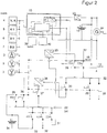
Fig. 2 einen Niederspannungsverteiler mit mehreren EIN-AUS-Schaltern und weiteren Komponenten. -
Fig. 1 zeigt einen Schaltplan eines EIN-AUS-Schalters, der im Folgenden näher erläutert wird. - Der EIN-AUS-Schalter ist mittels einer Busleitung 1 an einer Microprozessoreinheit 13 gekoppelt. Die Busleitung kann als Datenbus und / oder Adressbus eingerichtet sein. Mittels einer Strommesseinrichtung 2, z.B. eine Messspule und ein Digitalwandler, wird der Strom gemessen. Die Messwerte werden zusammen mit einer Zeitangabe über die Busleitung 1 an die Microprozessoreinheit 13 übermittelt (typisch für alle Schalter K1). Des Weiteren ist eine Spannungsmesseinrichtung 3 vorgesehen für eine Spannungsmessung am Schaltereingang über einen Digitalwandler, der die Messwerte über die Busleitung 1 an die Microprozessoreinheit 13 übermittelt (typisch für alle Schalter K1).
- An die Busleitung 1 ist ein erstes Modul 4 zur Datenübermittlung der Nenngrößen des Schalters an die Microprozessoreinheit 13 gekoppelt (typisch für alle Schalter K1). Ein zweites Modul 5 ist eingerichtet, eine Datenübermittlung der Schaltvorgänge eines Schaltrelais K1 über die Busleitung 1 an die Microprozessoreinheit 13 auszuführen (typisch für alle Schalter K1). Eine Datenübermittlung der Schaltvorgänge eines Tasters S1 erfolgt mittels eines dritten Moduls 6 über die Busleitung 1 an die Microprozessoreinheit 13 (typisch für alle Schalter K1). Schließlich ist ein viertes Modul 7 zur Datenübermittlung der Schaltvorgänge eines Tasters S2 über die Busleitung 1 an die Microprozessoreinheit 13 vorgesehen (typisch für alle Schalter K1).
- Der EIN-AUS-Schalter weist ein Schaltrelais K1 8 (NO, normal offen) für die EIN / AUS Schaltung der Spannung von einer Sammelschiene 22 (
Fig. 2 ) an einen Stromkreis. Das Schaltrelais K1 8 kann als Thyristor oder als Magnetspulschalter ausgeführt sein. Der Stromkreis ist mittels einer Abgangsklemme 10 gekoppelt. - Eine weitere Spannungsmesseinrichtung 9 ist zur Spannungsmessung am Schalterausgang eingerichtet. Mittels eines Digitaiwandlers wird der Messwert "Höhe der Spannung" über die Busleitung 1 an die Microprozessoreinheit 13 übermittelt (typisch für alle Schalter K1). Die Microprozessoreinheit 13 kann einen Prozessor und einen Speicher aufweisen und die Zeitpunkte jeglicher Veränderung abspeichern.
- Der EIN-AUS-Schalter wird mittels einer Pufferbatterie 14 mit einer Steuerspannung versorgt, z.B. 12 V, die als Steuerspannungen 12, 15 anliegen, z.B. 12 V GS Minus und 12 V GS Plus. Die Pufferbatterie 14 mit Handkurbelgenerator für die Steuerspannung ist Teil des Niederspannungsverteilers in
Fig. 2 und inFig. 1 nur vollständigkeitshalber dargestellt. Die Steuerspannungsanschlüsse sind inFig. 2 nur typisch dargestellt. - Der Microprozessoreinheit 13 ist nicht Teil des EIN-AUS-Schalters. Sie ist in
Fig. 1 nur vollständigkeitshalber dargestellt, um die Anbindung der Busleitung 1 zu verdeutlichen. Die Microprozessoreinheit 13 ist Teil des inFig. 2 gezeigten Niederspannungsverteilers. Die Microprozessoreinheit 13 kann auch außerhalb des Niederspannungsverteilers angeordnet sein. Mittels der Microprozessoreinheit 13 wird Software ausgeführt, weiche die abgebildete Überstrom- und / oder Kurzschlussauslösung sowie sonstige EIN-AUS Funktionen umfasst. - Der EIN-AUS-Schalter weist des Weiteren ein Schaltrelais S3 16 (NC, normal geschlossen) für den Steuerbefehl "Schalter K1 AUS" und ein Schaltrelais S4 17 (NO, normal offen) für den Steuerbefehl "Schalter K1 EIN" auf.
- Es sind ein Taster S1 18 (NO, normal offen) mit dem Steuerbefehl "Schalter K1 EIN", ein Hilfskontakt K1 19 (NO, normal offen) für Relais K1-Selbsthaltung und ein Taster S2 20 (NC, normal geschlossen) mit dem Steuerbefehl "Schalter K1 AUS" vorgesehen.
- Der EIN-AUS-Schalter umfasst weiterhin eine LED-Kontrollleuchte 11 für eine visuelle Anzeige, dass eine Spannung an am Schalterausgang anliegt. Eine Kontrollleuchte 21 stellt eine visuelle Anzeige dar, dass eine Spannung am Schaltereingang anliegt.
- Nachfolgend wird der in
Fig. 2 dargestellte Niederspannungsverteiler näher erläutert. - Der Verteiler umfasst eine erste Sammelschiene 22 und eine zweite Sammelschiene 22a. An der ersten Sammelschiene 22 kann eine Wechselspannung anliegen, z.B. 110V, 220 V, 230 V oder 380 V. Bei einer z.B. 380 Volt-Ausführung kann die Sammelschiene 22 als 3-Phasige (3-fache) Schiene ausgeführt sein. An der zweiten Sammelschiene 22a kann eine Gleichspannung anliegen, beispielsweise 12 V, 24 V oder 48 V.
- Ein Gleichspannungswandler 23 wandelt die Steuerspannung des Schalters auf eine Arbeitsspannung der Microprozessoreinheit 13 um, beispielsweise von 12 V= auf 3,5 V=.
- Ein Handgenerator 24 (z.B. eine Handkurbel) ermöglicht eine Ladung der Pufferbatterie 14 bei Testbetrieb und bei Inbetriebnahme des Verteilers.
- Ein Wechselrichter 25 (Gleichstrom-Wechselstrom) ist mittels eines Schalters K1 31 an die zweite Sammelschiene 22a (Gleichstromsammelschiene) und mittels eines Schalters K1 26 an die erste Sammelschiene 22 (Wechselstromschiene) zur Einspeisung der Gleichspannung gekoppelt.
- Der Schalter K1 26 gemäß
Fig. 1 wird hier z.B. zur Einspeisung durch den Wechselrichter 25 verwendet. Verschiedene Schalter K1 27 gemäßFig. 1 sind an verschiedene Einspeisestromkreise (Energieerzeugung) mit Wechselspannung gekoppelt (z.B. Verbundnetz, Notstromgenerator, Windkraftanlage, etc.). Das Bezugszeichen 28 ist ein Platzhalter (je nach Verteilergröße und Belegung in unterschiedlicher Anzahl) für weitere Schalter K1 nachFig. 1 . Der Schalter K1 29 nachFig. 1 koppelt an verschiedene Nutzungsstromkreise mit Wechselspannung (Energienutzung), z.B. Steckdosen, Waschmaschinenanschluss, Heizungszentralschalter, Zentralschalter für Alarmanlage usw. - Der Schalter K1 30 nach
Fig. 1 koppelt an einen Gleichrichter 38 zur Einspeisung der zweiten Sammelschiene 22a von der ersten Sammelschiene 22. - Der Schalter K1 31 nach
Fig. 1 koppelt an den Wechselrichter 25. - Der Schalter K1 32 nach
Fig. 1 koppelt an Nutzungsstromkreise mit Gleichspannung, z.B. Ladesteckdose Akkustaubsauger, LED-Beleuchtung, Gleichspannungshaushaltsgeräte etc. - Der Schalter K1 33 nach
Fig. 1 koppelt an einen Speicherstromkreis (Energiespeicherung), z.B. Speicherbatterieladestromkreis, Heißwasserbehälter, Warmwasserbehälter, Heizwasserbehälter, Hydrogengasproduktions- bzw. Speichereinheit etc. - Der Verteiler weist eine Speicherbatterie 34 auf, z.B. für 6 Stunden Teilbetrieb. Die Speicherbatterie 34 ist mit einem Schalter K1 35 nach
Fig. 1 gekoppelt. - Ein Schalter K1 36 nach
Fig. 1 dient zur Einspeisung von elektrischer Energie auf die zweite Sammelschiene 22a, z.B. mittels einer Solaranlage, einer Wassermühle, einer Brennstoffzelle, eines Thermogenerators etc. - Ein Schalter K1 37 nach
Fig. 1 dient zur Einspeisung von elektrischer Energie auf die zweite Sammelschiene 22a aus dem Gleichrichter 38. - Der Gleichrichter 38 koppelt an die erste Sammelschiene 22 zur Einspeisung der zweiten Sammelschiene 22a aus der Wechselspannung.
- Eine Schnittstelle 39 dient zur Datenübermittlung von Schaltern K1 aus dem Stromkreis (typisch für alle Schalter K1) an die Microprozessoreinheit 13.
- Eine Kommunikationsschnittstelle 40 (z.B. WLAN, Bluetooth, RS 232, Funktastersignal etc.) ermöglicht einen Datenaustausch des Prozessors mit anderen Geräten. Hierüber kann der Prozessor gesteuert werden und anschließend Signale an die Schalter K1 übertragen, um diese EIN oder AUS zu schalten.
- Im Folgenden werden weitere Ausführungsformen erläutert.
- Es handelt sich in einer Ausführungsform um einen sowohl computergesteuerten, digitalen und / oder mechanischen, auf Sammelschienen steckbaren Ein-Aus-Schalter für zwei verschiedene Ebenen der Niederspannung, z.B. in einem geeigneten Kunststoffgehäuse. Der Schalter kann technische Vorrichtungen für Strom- und Spannungsmessung sowie notwendige Digitalwandler und Hilfskontakte für die Signalgebung von verschiedenen Kenngrößen bzw. Schaltzuständen wie Stromwert und verschiedene relevante Spannungswerte zum Zeitpunkt t oder "Ein bzw. Aus" zum Zeitpunkt t aufweisen. Der Schalter besitzt anstatt herkömmlicher Bimetall- und Magnetspulenschutzelemente, entsprechende digitale, extern von einem Prozessor berechnete Schutzschaltfunktionen nach DIN VDE 0100-430 für Überlast- und / oder Kurzschlussabschaltung. Über die digital realisierten Leitungsschutzfunktionen hinaus kann der Schalter von sonstigen Schaltfunktionen, für die die Befehle mechanisch über einen Taster oder digital über eine CPU (Software) erzeugt werden, mit den Befehlen EIN und AUS angesteuert werden. So wird mittels Software ein Schalter realisiert, der normgerechte Überlast- und Kurzschlussauslösung mit Fernschaltfunktionen verbindet. Der Schalter kann als ein auf verschiedene Sammelschienen steckbares Element realisiert werden, sodass verschiedene Spannungsebenen bedient werden können.
- In einer weiteren Ausführungsform ist ein Ein-Aus-Schalter als elektronischer Sicherungs- und Steuerungsschalter mit integrierter Strom- und Spannungsmessung bereitgestellt. Der Ein-Aus-Schalter als Steuerungsschalter schaltet Stromkreise, an denen Geräte angeschlossen sind, die mit unterschiedlichen Gleichspannungen von z.B. 24 V Gleich- oder 220 V Wechselspannung betrieben werden. Der Ein-Aus-Schalter wird je nach Größe mittels eines Thyristors oder mittels einer mechanischen Magnetspule zugeschaltet. Der Schaltvorgang kann über einen Taster, der den Thyristor aktiviert oder die Magnetspule mit Steuerspannung versorgt und dadurch den magnetischen Kern bewegt und so jeweils den Stromkreis einschaltet, ausgelöst werden. Falls im Störfalle keine Steuerspannung ansteht, unterbricht der Ein-Aus-Schalter als so-genannter NO-Schalter (normally open, normal offen) die Spannungsversorgung des Stromkreises. Hierdurch wird sichergestellt, dass der Schalter bei Ausfall der Steuerspannung den zugehörigen Stromkreis unterbricht, beziehungsweise dieser nicht eingeschaltet werden kann. Der Ein-Aus-Schalter wird auch dann über den Steuerspannungswegfall ausgeschaltet, wenn aus Informationen, die aus Strom- und Spannungsmessung zur Verfügung stehen, errechnet wurde, dass ein Kurzschluss oder eine Überspannung nach DIN VDE 0100-430 bestehen. Wesentliche Informationen sind jene gemessene Stromstärke, die unter Abzug von Anlaufcharakteristiken der angeschlossenen Geräte klassisch als Kurzschlussstrom oder Überlaststrom eingestuft werden und normgemäß zwingend zur Abschaltung führen müssen. Bei Messung eines Kurzschlussstroms wird also die sofortige Abschaltung des Stromkreises veranlasst. Bei Messung eines Überlaststroms wird nach Maßgabe der Kurve eines üblichen Bimetalls bei der entsprechenden Stärke abgeschaltet. Diese Sicherheitsfunktionen sind im Verteiler festgelegt, in der Software gespeichert und können nicht geändert werden.
- Die Schaltgröße (Nominaler Wert) ist nach den Vorgaben der korrespondierenden Bimetalle-Charakteristiken festgelegt, in einem Identifikationschip eigens kategorisiert sowie entsprechend gut sichtbar schriftlich am Schaltergehäuse gekennzeichnet, z.B. 3 A=, 24 V. Die Identifizierung des Schalters bei der CPU erfolgt somit über Signalgabe über die Busleitung.
- Der Schalter ist somit für verschiedene elektrische Leistungen sowie für verschiedentlich angeordnete Spannungsebenen geeignet und besitzt entsprechend an einer Seite räumlich angeordnete Anschlussklemmen. Die Anschlussklemmenklemmen sind: 220 V Wechselstrom oder 24 V Gleichstrom, PE, - für Gleichstrom und N. Die räumliche Anordnung der Sammelschienen im Schaltkasten ist kennzeichnend für die Spannungsebene. Die Spannung des Stromkreises an der anderen Seite des Schalters ist durch die angeschlossene Sammelschiene festgelegt.
- Der Schalter kann folgende Komponenten aufweisen:
- Gehäuse aus Kunststoff
- Sammelschienenklemme für die Spannungsabnahme am der Sammelschiene
- Anschlussklemmen, Schraubverbindung
- Platine mit Strom- und Spannungsmessung mit Digitalisierung
- Thyristor oder Magnetspulschalter K1
- Zwei Steuerschalter S1, S2
- Digitale Identifizierung
- Identifizierungsmodul (EE - Energieerzeugung, ES - Energiespeicherung, EN - Energienutzung)
- Taster mit Hilfskontakt und LED EIN (z.B. rot)
- Taster mit Hilfskontakt und LED AUS (z.B. grün)
- Steckverbindung Bus
- Das EIN-AUS-Schaltergehäuse entspricht den räumlichen Anforderungen und Anordnungen der jeweils notwendigen elektronischen und mechanischen Schalterkomponenten und der Steckverbindungen an den Sammelschienen. Das Gehäuse kann aus Kunststoff gebildet sein.
- Der EIN-AUS-Schalter kann über einen Prozessor ausgeschaltet werden gemäß DIN VDE 0100-430 Oktober 2010 Schutz bei Überstrom falls
- ein plötzlicher Anstieg des Stromes stattfindet über den Nennwert des Stromkreises hinaus (Ereignis Kurzschluss). Anlaufströme der angeschlossenen Geräte sollen von der Logik nicht als Kurzschluss gewertet werden. (Leitungsschutzschalterfunktion)
- ein Strom über den Nennwert des Stromkreises ansteht, der so lange anhält, bis nach der korrespondierenden Bimetall-Anordnung eine Wärmeentwicklung entstanden ist, die zur Auslösung des Bimetall-Schalters führen würde (Ereignis Überlast). (Leitungsschutzschalterfunktion)
- Ein- und Ausschaltung über Taster (manuelle Schaltfunktion)
- Ferngeschaltet ein/aus über softwaregesteuerten Prozessor. (Schaltaktorfunktion)
- Der Ein-Aus-Schalter hat eine einprogrammierte digitale Identifizierung und Signalgebung, die von einem Prozessor, eingebaut im Energieverteilergehäuse oder extern hiervon, zusammen mit den Strom- und Spannungsmesswerten des betreffenden Stromkreises erfasst werden. Es werden über die Busverbindung am EIN-AUS-Schaltergehäuse folgende Daten abgerufen und an den Prozessor (z.B. automatisch über Bus) geleitet (und ggf. zeitbezogen gespeichert) oder über manuelle Eintragung eingegeben:
- Schalteridentifizierung (Info-Chip, Nenngrößen über Bus)
- Position auf der Sammelschiene (manuell)
- Stromkreisidentifizierung/-zuordnung (manuell)
- Signal Schalter an Sammelschienen geklemmt (LED und digitalisiert über Digitalwandler, Bus)
- Spannungswert (digitalisiert über Digitalwandler, Bus)
- Schalter an Stromkreis geklemmt (manuell)
- Signal Stromwert (digitalisiert)
- Signal Schalter Ein (LED und digitalisiert über Digitalwandler, Bus)
- Signal Schalter Aus
- Steuerung Schalter Ein
- Steuerung Schalter Aus
- Der Energieverteiler kann folgende Komponenten aufweisen:
- Sammelschiene 220 V WS (WS - Wechselspannung) mit Modulen EE (Energieerzeugung), ES (Energiespeicherung), EN (Energienutzung)
- Sammelschiene 24 V GS (GS - Gleichspannung) mit Modulen EE, ES, EN
- Identifizierung (Nummerierung) der EE, ES, EN Module und der Schalterpositionen
- GS/WS Wandler und WS/GS Wandler
- Batterie Steuerspannung mit Ladegerät 24V=>12V=
- Handkurbelgenerator 12V
- Mikroprozessoreinheit mit Speicherfunktion
- Anschluss für Datenübertragung
- Mit dieser Offenbarung werden verschiedene grundsätzliche Erneuerungen für die Domestizierung von Erneuerbaren Energien angesteuert. Ein Aspekt sind die computergesteuerte Kurzschlussabschaltung und Überstromabschaltung durch den Ein-Aus-Schalter in Verbindung mit einer mechanischen und einer Prozessorgesteuerten Ein - und Ausschaltung durch den Nutzer. Ein weiterer Aspekt ist der Einbau zweier Spannungsebenen im Energieverteiler, die die Nutzung von Stromkreisen mit entsprechenden Energiespeichersystemen und entsprechenden Nutzern ermöglichen. Hierdurch werden der Leitungsschutzschalter, ein herkömmlicher Schalter und ein prozessorgesteuerter Schaltaktor in einem einzigen Schalter verbunden. Die Computersteuerung eröffnet eine Vielzahl von Möglichkeiten und Chancen der Fernsteuerung und Automation von Energiespar- und Steuerungsaufgaben.
- Die in der Beschreibung, den Ansprüchen und den Figuren offenbarten Merkmale können sowohl einzeln als auch in beliebiger Kombination miteinander für die Verwirklichung von Ausführungsformen relevant sein.
-
- 1 Busleitung
- 2 Strommesseinrichtung
- 3 Spannungsmesseinrichtung
- 4 erstes Modul zur Datenübermittlung der Nenngrößen des Schalters
- 5 zweites Modul zur Datenübermittlung der Schaltvorgänge von Relais K1
- 6 drittes Modul zur Datenübermittlung der Schaltvorgänge von Taster S1
- 7 viertes Modul zur Datenübermittlung der Schaltvorgänge von Taster S2
- 8 Schaltrelais K1
- 9 weitere Spannungsmesseinrichtung
- 10 Abgangsklemme
- 11 LED-Kontrollleuchte
- 12 Steuerspannung
- 13 Microprozessoreinheit
- 14 Pufferbatterie
- 15 Steuerspannung
- 16 Schaltrelais S3
- 17 Schaltrelais S4
- 18 Taster S1
- 19 Hilfskontakt K1
- 20 Taster S2
- 21 Kontrollleuchte
- 22 / 22a erste und zweite Sammelschiene (eventuell 3-Phasig)
- 23 Gleichspannungswandler
- 24 Handkurbelgenerator
- 25 Wechselrichter
- 26 Schalter K1
- 27 Verschiedene Schalter K1
- 28 Platzhalter
- 29 Schalter K1
- 30 Schalter K1
- 31 Schalter K1
- 32 Schalter K1
- 33 Schalter K1
- 34 Speicherbatterie
- 35 Schalter K1
- 36 Schalter K1
- 37 Schalter K1
- 38 Gleichrichter
- 39 Schnittstelle
- 40 Kommunikationsschnittstelle
Claims (8)
- Ein-Aus-Schalter, mit- einer elektronischen Schalteinrichtung, die mittels eines Steuersignals zwischen einem ersten Zustand EIN und einem zweiten Zustand AUS schaltbar ist, und- einer digitalen Leitungsschutzschaltung, die eingerichtet ist, anhand einer Leitungsschutzfunktion eine Abschaltung auszuführen, wenn ein Schwellwert überschritten wird.
- Ein-Aus-Schalter nach Anspruch 1, weiter eine manuelle Schalteinrichtung aufweisend, wobei der Schalter mittels der manuellen Schalteinrichtung zwischen dem ersten Zustand und dem zweiten Zustand schaltbar ist.
- Ein-Aus-Schalter nach Anspruch 1 oder 2, weiter eine Strommesseinrichtung aufweisend, wobei die digitale Leitungsschutzschaltung eingerichtet ist, eine Abschaltung auszuführen, wenn ein mittels der Strommesseinrichtung bestimmter Strom einen Schwellwert überschreitet.
- Ein-Aus-Schalter nach Anspruch 3, wobei die digitale Leitungsschutzschaltung weiter eingerichtet ist, eine Abschaltung auszuführen, wenn mittels der Strommesseinrichtung ein Kurzschlussstrom bestimmt wird.
- Ein-Aus-Schalter nach einem der vorangehenden Ansprüche, weiter eine oder mehrere Spannungsmesseinrichtungen aufweisend.
- Ein-Aus-Schalter nach einem der vorangehenden Ansprüche, weiter eine erste Anschlussklemme und eine zweite Anschlussklemme aufweisend, wobei die erste Anschlussklemme einen Anschluss des Schalters an eine erste Spannungsebene ermöglicht und wobei die zweite Anschlussklemme einen Anschluss des Schalters an eine zweite Spannungsebene ermöglicht.
- Ein-Aus-Schalter nach einem der vorangehenden Ansprüche, weiter eine Busleitung aufweisend, die eingerichtet ist, Daten an einen Prozessor zu übertragen.
- Schaltanlage mit einem Prozessor und wenigstens einem Ein-Aus-Schalter nach einem der vorangehenden Ansprüche, wobei der wenigstens eine Ein-Aus-Schalter mit dem Prozessor datentechnisch gekoppelt ist.
Applications Claiming Priority (1)
| Application Number | Priority Date | Filing Date | Title |
|---|---|---|---|
| DE102017104421.3A DE102017104421A1 (de) | 2017-03-02 | 2017-03-02 | EIN-AUS-Schalter und Schaltanlage |
Publications (2)
| Publication Number | Publication Date |
|---|---|
| EP3370245A1 true EP3370245A1 (de) | 2018-09-05 |
| EP3370245B1 EP3370245B1 (de) | 2021-11-24 |
Family
ID=61256777
Family Applications (1)
| Application Number | Title | Priority Date | Filing Date |
|---|---|---|---|
| EP18158046.5A Active EP3370245B1 (de) | 2017-03-02 | 2018-02-22 | Ein-aus-schalter und schaltanlage |
Country Status (2)
| Country | Link |
|---|---|
| EP (1) | EP3370245B1 (de) |
| DE (1) | DE102017104421A1 (de) |
Citations (5)
| Publication number | Priority date | Publication date | Assignee | Title |
|---|---|---|---|---|
| DE102006020702A1 (de) * | 2006-05-04 | 2007-11-15 | Moeller Gmbh | Schutzschalter für Motorschutz und/oder Leitungsschutz |
| US20120001706A1 (en) * | 2010-06-30 | 2012-01-05 | Daniel Patrick Heckenkamp | Electronic overload relay switch actuation |
| WO2012007494A1 (de) * | 2010-07-16 | 2012-01-19 | Magna E-Car Systems Gmbh & Co Og | Überstromschalter, verwendung eines überstromschalters und elektrokraftfahrzeug mit einem überstromschalter |
| US20120098347A1 (en) * | 2010-10-20 | 2012-04-26 | Schneider Electric USA, Inc. | Electronic circuit breaker with alternate mode of operation using auxiliary power source |
| US20120176719A1 (en) * | 2011-01-11 | 2012-07-12 | Carlino Harry J | Trip unit providing remote electrical signal to remotely indicate that an arc reduction maintenance mode is remotely enabled, and electrical switching apparatus including the same |
-
2017
- 2017-03-02 DE DE102017104421.3A patent/DE102017104421A1/de not_active Withdrawn
-
2018
- 2018-02-22 EP EP18158046.5A patent/EP3370245B1/de active Active
Patent Citations (5)
| Publication number | Priority date | Publication date | Assignee | Title |
|---|---|---|---|---|
| DE102006020702A1 (de) * | 2006-05-04 | 2007-11-15 | Moeller Gmbh | Schutzschalter für Motorschutz und/oder Leitungsschutz |
| US20120001706A1 (en) * | 2010-06-30 | 2012-01-05 | Daniel Patrick Heckenkamp | Electronic overload relay switch actuation |
| WO2012007494A1 (de) * | 2010-07-16 | 2012-01-19 | Magna E-Car Systems Gmbh & Co Og | Überstromschalter, verwendung eines überstromschalters und elektrokraftfahrzeug mit einem überstromschalter |
| US20120098347A1 (en) * | 2010-10-20 | 2012-04-26 | Schneider Electric USA, Inc. | Electronic circuit breaker with alternate mode of operation using auxiliary power source |
| US20120176719A1 (en) * | 2011-01-11 | 2012-07-12 | Carlino Harry J | Trip unit providing remote electrical signal to remotely indicate that an arc reduction maintenance mode is remotely enabled, and electrical switching apparatus including the same |
Also Published As
| Publication number | Publication date |
|---|---|
| DE102017104421A1 (de) | 2018-09-06 |
| EP3370245B1 (de) | 2021-11-24 |
Similar Documents
| Publication | Publication Date | Title |
|---|---|---|
| DE3114550C2 (de) | ||
| DE3114549C2 (de) | ||
| EP1841050B1 (de) | Verfahren zur Umwandlung einer Gleichspannung in eine dreiphasige Wechselspannung | |
| EP3390133B1 (de) | Sicherheitsmodul und ladestation mit sicherheitsmodul | |
| DE3114544C2 (de) | ||
| DE3114551C2 (de) | ||
| DE102017215820B4 (de) | Leistungsschalter und Verfahren | |
| DE102014102352A1 (de) | Batteriespeichersystem mit Störlichtbogenschutz, Energieumwandlungssystem und Schutzverfahren | |
| DE102018210875A1 (de) | Spannungswandlungseinheit | |
| EP3111526A1 (de) | Netzknoten für ein stromnetz, regeltransformator für einen netzknoten und verfahren zum betreiben eines netzknotens | |
| EP1782517B1 (de) | Vorrichtung zur sicheren trennung einer kraftwerksanlage von einem netz bei einem netzfehler | |
| DE102016223264A1 (de) | Schutzschalter | |
| DE102013217743A1 (de) | Verfahren und Steuergerät zum Begrenzen einer elektrischen Belastung in einem Netzzweig eines elektrischen Netzes | |
| DE102017011373A1 (de) | Mess- und Steuerelektronik für Niederspannungsschaltanlagen | |
| US3271580A (en) | Load shedding apparatus | |
| DE3114548C2 (de) | ||
| EP3370245B1 (de) | Ein-aus-schalter und schaltanlage | |
| DE102019202474A1 (de) | Fehlerstromschutzeinheit und Verfahren | |
| DE102007016635A1 (de) | Vorrichtung und Verfahren zum Verteilen elektrischer Energie | |
| AT509836A2 (de) | Elektronische sicherung | |
| EP2880731B1 (de) | Fehlererkennung in einem energieversorgungsnetz mit dezentraler energieeinspeisung | |
| DE102016212944A1 (de) | Energieverteilungssystem | |
| DE202018103077U1 (de) | Portables Gerät zur Eigenverbrauchsoptimierung | |
| DE102018115696A1 (de) | Mehrfachmessvorrichtung und Leitungsschutzschalter | |
| CN219554656U (zh) | 一种检修电源配电优化设备 |
Legal Events
| Date | Code | Title | Description |
|---|---|---|---|
| PUAI | Public reference made under article 153(3) epc to a published international application that has entered the european phase |
Free format text: ORIGINAL CODE: 0009012 |
|
| STAA | Information on the status of an ep patent application or granted ep patent |
Free format text: STATUS: THE APPLICATION HAS BEEN PUBLISHED |
|
| AK | Designated contracting states |
Kind code of ref document: A1 Designated state(s): AL AT BE BG CH CY CZ DE DK EE ES FI FR GB GR HR HU IE IS IT LI LT LU LV MC MK MT NL NO PL PT RO RS SE SI SK SM TR |
|
| AX | Request for extension of the european patent |
Extension state: BA ME |
|
| STAA | Information on the status of an ep patent application or granted ep patent |
Free format text: STATUS: REQUEST FOR EXAMINATION WAS MADE |
|
| 17P | Request for examination filed |
Effective date: 20190305 |
|
| RBV | Designated contracting states (corrected) |
Designated state(s): AL AT BE BG CH CY CZ DE DK EE ES FI FR GB GR HR HU IE IS IT LI LT LU LV MC MK MT NL NO PL PT RO RS SE SI SK SM TR |
|
| STAA | Information on the status of an ep patent application or granted ep patent |
Free format text: STATUS: EXAMINATION IS IN PROGRESS |
|
| 17Q | First examination report despatched |
Effective date: 20191217 |
|
| STAA | Information on the status of an ep patent application or granted ep patent |
Free format text: STATUS: EXAMINATION IS IN PROGRESS |
|
| GRAP | Despatch of communication of intention to grant a patent |
Free format text: ORIGINAL CODE: EPIDOSNIGR1 |
|
| STAA | Information on the status of an ep patent application or granted ep patent |
Free format text: STATUS: GRANT OF PATENT IS INTENDED |
|
| INTG | Intention to grant announced |
Effective date: 20210831 |
|
| GRAS | Grant fee paid |
Free format text: ORIGINAL CODE: EPIDOSNIGR3 |
|
| GRAA | (expected) grant |
Free format text: ORIGINAL CODE: 0009210 |
|
| STAA | Information on the status of an ep patent application or granted ep patent |
Free format text: STATUS: THE PATENT HAS BEEN GRANTED |
|
| AK | Designated contracting states |
Kind code of ref document: B1 Designated state(s): AL AT BE BG CH CY CZ DE DK EE ES FI FR GB GR HR HU IE IS IT LI LT LU LV MC MK MT NL NO PL PT RO RS SE SI SK SM TR |
|
| REG | Reference to a national code |
Ref country code: GB Ref legal event code: FG4D Free format text: NOT ENGLISH |
|
| REG | Reference to a national code |
Ref country code: DE Ref legal event code: R096 Ref document number: 502018007933 Country of ref document: DE |
|
| REG | Reference to a national code |
Ref country code: AT Ref legal event code: REF Ref document number: 1450495 Country of ref document: AT Kind code of ref document: T Effective date: 20211215 |
|
| REG | Reference to a national code |
Ref country code: IE Ref legal event code: FG4D Free format text: LANGUAGE OF EP DOCUMENT: GERMAN |
|
| REG | Reference to a national code |
Ref country code: LT Ref legal event code: MG9D |
|
| REG | Reference to a national code |
Ref country code: NL Ref legal event code: MP Effective date: 20211124 |
|
| PG25 | Lapsed in a contracting state [announced via postgrant information from national office to epo] |
Ref country code: RS Free format text: LAPSE BECAUSE OF FAILURE TO SUBMIT A TRANSLATION OF THE DESCRIPTION OR TO PAY THE FEE WITHIN THE PRESCRIBED TIME-LIMIT Effective date: 20211124 Ref country code: LT Free format text: LAPSE BECAUSE OF FAILURE TO SUBMIT A TRANSLATION OF THE DESCRIPTION OR TO PAY THE FEE WITHIN THE PRESCRIBED TIME-LIMIT Effective date: 20211124 Ref country code: FI Free format text: LAPSE BECAUSE OF FAILURE TO SUBMIT A TRANSLATION OF THE DESCRIPTION OR TO PAY THE FEE WITHIN THE PRESCRIBED TIME-LIMIT Effective date: 20211124 Ref country code: BG Free format text: LAPSE BECAUSE OF FAILURE TO SUBMIT A TRANSLATION OF THE DESCRIPTION OR TO PAY THE FEE WITHIN THE PRESCRIBED TIME-LIMIT Effective date: 20220224 |
|
| PG25 | Lapsed in a contracting state [announced via postgrant information from national office to epo] |
Ref country code: IS Free format text: LAPSE BECAUSE OF FAILURE TO SUBMIT A TRANSLATION OF THE DESCRIPTION OR TO PAY THE FEE WITHIN THE PRESCRIBED TIME-LIMIT Effective date: 20220324 Ref country code: SE Free format text: LAPSE BECAUSE OF FAILURE TO SUBMIT A TRANSLATION OF THE DESCRIPTION OR TO PAY THE FEE WITHIN THE PRESCRIBED TIME-LIMIT Effective date: 20211124 Ref country code: PT Free format text: LAPSE BECAUSE OF FAILURE TO SUBMIT A TRANSLATION OF THE DESCRIPTION OR TO PAY THE FEE WITHIN THE PRESCRIBED TIME-LIMIT Effective date: 20220324 Ref country code: PL Free format text: LAPSE BECAUSE OF FAILURE TO SUBMIT A TRANSLATION OF THE DESCRIPTION OR TO PAY THE FEE WITHIN THE PRESCRIBED TIME-LIMIT Effective date: 20211124 Ref country code: NO Free format text: LAPSE BECAUSE OF FAILURE TO SUBMIT A TRANSLATION OF THE DESCRIPTION OR TO PAY THE FEE WITHIN THE PRESCRIBED TIME-LIMIT Effective date: 20220224 Ref country code: NL Free format text: LAPSE BECAUSE OF FAILURE TO SUBMIT A TRANSLATION OF THE DESCRIPTION OR TO PAY THE FEE WITHIN THE PRESCRIBED TIME-LIMIT Effective date: 20211124 Ref country code: LV Free format text: LAPSE BECAUSE OF FAILURE TO SUBMIT A TRANSLATION OF THE DESCRIPTION OR TO PAY THE FEE WITHIN THE PRESCRIBED TIME-LIMIT Effective date: 20211124 Ref country code: HR Free format text: LAPSE BECAUSE OF FAILURE TO SUBMIT A TRANSLATION OF THE DESCRIPTION OR TO PAY THE FEE WITHIN THE PRESCRIBED TIME-LIMIT Effective date: 20211124 Ref country code: GR Free format text: LAPSE BECAUSE OF FAILURE TO SUBMIT A TRANSLATION OF THE DESCRIPTION OR TO PAY THE FEE WITHIN THE PRESCRIBED TIME-LIMIT Effective date: 20220225 Ref country code: ES Free format text: LAPSE BECAUSE OF FAILURE TO SUBMIT A TRANSLATION OF THE DESCRIPTION OR TO PAY THE FEE WITHIN THE PRESCRIBED TIME-LIMIT Effective date: 20211124 |
|
| PG25 | Lapsed in a contracting state [announced via postgrant information from national office to epo] |
Ref country code: SM Free format text: LAPSE BECAUSE OF FAILURE TO SUBMIT A TRANSLATION OF THE DESCRIPTION OR TO PAY THE FEE WITHIN THE PRESCRIBED TIME-LIMIT Effective date: 20211124 Ref country code: SK Free format text: LAPSE BECAUSE OF FAILURE TO SUBMIT A TRANSLATION OF THE DESCRIPTION OR TO PAY THE FEE WITHIN THE PRESCRIBED TIME-LIMIT Effective date: 20211124 Ref country code: RO Free format text: LAPSE BECAUSE OF FAILURE TO SUBMIT A TRANSLATION OF THE DESCRIPTION OR TO PAY THE FEE WITHIN THE PRESCRIBED TIME-LIMIT Effective date: 20211124 Ref country code: EE Free format text: LAPSE BECAUSE OF FAILURE TO SUBMIT A TRANSLATION OF THE DESCRIPTION OR TO PAY THE FEE WITHIN THE PRESCRIBED TIME-LIMIT Effective date: 20211124 Ref country code: DK Free format text: LAPSE BECAUSE OF FAILURE TO SUBMIT A TRANSLATION OF THE DESCRIPTION OR TO PAY THE FEE WITHIN THE PRESCRIBED TIME-LIMIT Effective date: 20211124 Ref country code: CZ Free format text: LAPSE BECAUSE OF FAILURE TO SUBMIT A TRANSLATION OF THE DESCRIPTION OR TO PAY THE FEE WITHIN THE PRESCRIBED TIME-LIMIT Effective date: 20211124 |
|
| REG | Reference to a national code |
Ref country code: DE Ref legal event code: R097 Ref document number: 502018007933 Country of ref document: DE |
|
| PG25 | Lapsed in a contracting state [announced via postgrant information from national office to epo] |
Ref country code: MC Free format text: LAPSE BECAUSE OF FAILURE TO SUBMIT A TRANSLATION OF THE DESCRIPTION OR TO PAY THE FEE WITHIN THE PRESCRIBED TIME-LIMIT Effective date: 20211124 |
|
| PLBE | No opposition filed within time limit |
Free format text: ORIGINAL CODE: 0009261 |
|
| STAA | Information on the status of an ep patent application or granted ep patent |
Free format text: STATUS: NO OPPOSITION FILED WITHIN TIME LIMIT |
|
| REG | Reference to a national code |
Ref country code: BE Ref legal event code: MM Effective date: 20220228 |
|
| PG25 | Lapsed in a contracting state [announced via postgrant information from national office to epo] |
Ref country code: LU Free format text: LAPSE BECAUSE OF NON-PAYMENT OF DUE FEES Effective date: 20220222 Ref country code: AL Free format text: LAPSE BECAUSE OF FAILURE TO SUBMIT A TRANSLATION OF THE DESCRIPTION OR TO PAY THE FEE WITHIN THE PRESCRIBED TIME-LIMIT Effective date: 20211124 |
|
| 26N | No opposition filed |
Effective date: 20220825 |
|
| PG25 | Lapsed in a contracting state [announced via postgrant information from national office to epo] |
Ref country code: SI Free format text: LAPSE BECAUSE OF FAILURE TO SUBMIT A TRANSLATION OF THE DESCRIPTION OR TO PAY THE FEE WITHIN THE PRESCRIBED TIME-LIMIT Effective date: 20211124 |
|
| PG25 | Lapsed in a contracting state [announced via postgrant information from national office to epo] |
Ref country code: IE Free format text: LAPSE BECAUSE OF NON-PAYMENT OF DUE FEES Effective date: 20220222 |
|
| PG25 | Lapsed in a contracting state [announced via postgrant information from national office to epo] |
Ref country code: BE Free format text: LAPSE BECAUSE OF NON-PAYMENT OF DUE FEES Effective date: 20220228 |
|
| PGFP | Annual fee paid to national office [announced via postgrant information from national office to epo] |
Ref country code: FR Payment date: 20230310 Year of fee payment: 6 |
|
| PG25 | Lapsed in a contracting state [announced via postgrant information from national office to epo] |
Ref country code: IT Free format text: LAPSE BECAUSE OF FAILURE TO SUBMIT A TRANSLATION OF THE DESCRIPTION OR TO PAY THE FEE WITHIN THE PRESCRIBED TIME-LIMIT Effective date: 20211124 |
|
| PG25 | Lapsed in a contracting state [announced via postgrant information from national office to epo] |
Ref country code: HU Free format text: LAPSE BECAUSE OF FAILURE TO SUBMIT A TRANSLATION OF THE DESCRIPTION OR TO PAY THE FEE WITHIN THE PRESCRIBED TIME-LIMIT; INVALID AB INITIO Effective date: 20180222 |
|
| PGFP | Annual fee paid to national office [announced via postgrant information from national office to epo] |
Ref country code: AT Payment date: 20240209 Year of fee payment: 7 |
|
| PG25 | Lapsed in a contracting state [announced via postgrant information from national office to epo] |
Ref country code: MK Free format text: LAPSE BECAUSE OF FAILURE TO SUBMIT A TRANSLATION OF THE DESCRIPTION OR TO PAY THE FEE WITHIN THE PRESCRIBED TIME-LIMIT Effective date: 20211124 Ref country code: CY Free format text: LAPSE BECAUSE OF FAILURE TO SUBMIT A TRANSLATION OF THE DESCRIPTION OR TO PAY THE FEE WITHIN THE PRESCRIBED TIME-LIMIT Effective date: 20211124 |
|
| PGFP | Annual fee paid to national office [announced via postgrant information from national office to epo] |
Ref country code: DE Payment date: 20240229 Year of fee payment: 7 Ref country code: GB Payment date: 20240208 Year of fee payment: 7 Ref country code: CH Payment date: 20240301 Year of fee payment: 7 |