EP3370026A1 - Twisted pipe heat exchanger - Google Patents
Twisted pipe heat exchanger Download PDFInfo
- Publication number
- EP3370026A1 EP3370026A1 EP17797221.3A EP17797221A EP3370026A1 EP 3370026 A1 EP3370026 A1 EP 3370026A1 EP 17797221 A EP17797221 A EP 17797221A EP 3370026 A1 EP3370026 A1 EP 3370026A1
- Authority
- EP
- European Patent Office
- Prior art keywords
- pipe
- area
- twisted tube
- heat exchanger
- heat insulator
- Prior art date
- Legal status (The legal status is an assumption and is not a legal conclusion. Google has not performed a legal analysis and makes no representation as to the accuracy of the status listed.)
- Granted
Links
Images


Classifications
-
- F—MECHANICAL ENGINEERING; LIGHTING; HEATING; WEAPONS; BLASTING
- F28—HEAT EXCHANGE IN GENERAL
- F28D—HEAT-EXCHANGE APPARATUS, NOT PROVIDED FOR IN ANOTHER SUBCLASS, IN WHICH THE HEAT-EXCHANGE MEDIA DO NOT COME INTO DIRECT CONTACT
- F28D7/00—Heat-exchange apparatus having stationary tubular conduit assemblies for both heat-exchange media, the media being in contact with different sides of a conduit wall
- F28D7/0008—Heat-exchange apparatus having stationary tubular conduit assemblies for both heat-exchange media, the media being in contact with different sides of a conduit wall the conduits for one medium being in heat conductive contact with the conduits for the other medium
- F28D7/0016—Heat-exchange apparatus having stationary tubular conduit assemblies for both heat-exchange media, the media being in contact with different sides of a conduit wall the conduits for one medium being in heat conductive contact with the conduits for the other medium the conduits for one medium or the conduits for both media being bent
-
- F—MECHANICAL ENGINEERING; LIGHTING; HEATING; WEAPONS; BLASTING
- F28—HEAT EXCHANGE IN GENERAL
- F28F—DETAILS OF HEAT-EXCHANGE AND HEAT-TRANSFER APPARATUS, OF GENERAL APPLICATION
- F28F19/00—Preventing the formation of deposits or corrosion, e.g. by using filters or scrapers
-
- F—MECHANICAL ENGINEERING; LIGHTING; HEATING; WEAPONS; BLASTING
- F28—HEAT EXCHANGE IN GENERAL
- F28D—HEAT-EXCHANGE APPARATUS, NOT PROVIDED FOR IN ANOTHER SUBCLASS, IN WHICH THE HEAT-EXCHANGE MEDIA DO NOT COME INTO DIRECT CONTACT
- F28D7/00—Heat-exchange apparatus having stationary tubular conduit assemblies for both heat-exchange media, the media being in contact with different sides of a conduit wall
- F28D7/02—Heat-exchange apparatus having stationary tubular conduit assemblies for both heat-exchange media, the media being in contact with different sides of a conduit wall the conduits being helically coiled
- F28D7/024—Heat-exchange apparatus having stationary tubular conduit assemblies for both heat-exchange media, the media being in contact with different sides of a conduit wall the conduits being helically coiled the conduits of only one medium being helically coiled tubes, the coils having a cylindrical configuration
-
- F—MECHANICAL ENGINEERING; LIGHTING; HEATING; WEAPONS; BLASTING
- F28—HEAT EXCHANGE IN GENERAL
- F28F—DETAILS OF HEAT-EXCHANGE AND HEAT-TRANSFER APPARATUS, OF GENERAL APPLICATION
- F28F2210/00—Heat exchange conduits
- F28F2210/06—Heat exchange conduits having walls comprising obliquely extending corrugations, e.g. in the form of threads
-
- F—MECHANICAL ENGINEERING; LIGHTING; HEATING; WEAPONS; BLASTING
- F28—HEAT EXCHANGE IN GENERAL
- F28F—DETAILS OF HEAT-EXCHANGE AND HEAT-TRANSFER APPARATUS, OF GENERAL APPLICATION
- F28F2270/00—Thermal insulation; Thermal decoupling
Definitions
- the present invention relates to a twisted tube heat exchanger including a first pipe, and a second pipe installed spirally on a periphery of the first pipe.
- a heat exchanger has been known that includes a first pipe, and a second pipe installed on a periphery of the first pipe and in which a first fluid such as water flowing through the first pipe is heated by refrigerant flowing through the second pipe (see, for example, Patent Literature 1).
- the second pipe is placed along a length direction of the first pipe.
- the first pipe and the second pipe are arranged in parallel.
- peripheries of the first pipe and the second pipe are covered with a resin layer and the second pipe is placed in close contact with the first pipe.
- the resin layer covering the peripheries of the first pipe and the second pipe also serves as a heat insulator.
- the resin layer is provided on the peripheries of the first pipe and the second pipe by extrusion process.
- the twisted tube heat exchanger includes a first pipe with a spiral groove formed on a periphery and a second pipe wound around the groove on the first pipe. That is, the second pipe is installed spirally on the periphery of the first pipe.
- Patent Literature 1 Japanese Unexamined Patent Application Publication No. 2004-347178
- the resin layer serving as a heat insulator is formed by extrusion process. That is, the heat exchanger described in Patent Literature 1 is configured such that the heat insulator is installed on the entire heat exchanger. Thus, a configuration in which a heat insulator is installed in such a way as described in Patent Literature 1 has a problem of increased material costs of the heat exchanger.
- the twisted tube heat exchanger has a complicated shape in which the second pipe is installed spirally on the periphery of the first pipe. Consequently, it is practically impossible to form a resin layer on the peripheries of the twisted tube heat exchanger by extrusion process.
- the conventional twisted tube heat exchanger has a problem in that the second pipe is corroded because a heat insulating layer cannot be formed on the peripheries.
- opposite ends of the second pipe are connected with a pipe used to supply refrigerant to the second pipe and a pipe through which the refrigerant flows out of the second pipe, and thus are not wound around the periphery of the first pipe. Consequently, a mid-portion of the second pipe is wound around a periphery of a mid-portion of the first pipe. Then, the part of the second pipe that is wound around the periphery of the first pipe is joined to the first pipe by soldering or another joining method.
- first area an area in which the first pipe and the second pipe are joined together
- second area an area in which the first pipe and the second pipe are not joined together
- the first fluid flowing into the first pipe flows first in the second area. Subsequently, the first fluid in the first pipe flows into the first area and is heated by the refrigerant flowing through the second pipe. That is, the first fluid flowing through a section of the first pipe that is located in the second area is yet to be heated by the refrigerant, and thus remains at a low temperature. Consequently, the section of the first pipe that is located in the second area is at a lower temperature than ambient temperature and tends to cause condensation. Also, in the second area, in which the first pipe and the second pipe are not joined together, a gap is formed between the first pipe and the second pipe.
- the present invention has been made to solve the above problem and has an object to provide a twisted tube heat exchanger that can inhibit corrosion of the second pipe and curb increases in material costs.
- a twisted tube heat exchanger includes a twisted tube, and a heat insulator.
- the twisted tube includes a first pipe having a spiral groove formed on a periphery of the first pipe and allowing a first fluid to flow through the first pipe, and a second pipe having a part wound around the spiral groove on the first pipe and allowing refrigerant that heats the first fluid to flow through the second pipe.
- An area in which the first pipe and the second pipe are joined together is defined as a first area, and an area that is located closer to an end side of the first pipe than is the first area and in which the first pipe and the second pipe are not joined together is defined as a second area.
- the heat insulator is wound around a certain area including a boundary region between the first area and the second area, covering peripheries of the first pipe and the second pipe in the boundary region and a periphery of the first pipe in the second area.
- the twisted tube heat exchanger according to an embodiment of the present invention can be used as a configuration in which the first fluid flows from the second area to the first area.
- the heat insulator is wound, covering the peripheries of the first pipe and the second pipe in the boundary region between the first area and the second area as well as the periphery of the first pipe in the second area. That is, in the twisted tube heat exchanger according to the embodiment of the present invention, the heat insulator is wound around a portion in which condensed water bridging between the first pipe and the second pipe acts as a thermogalvanic cell, causing corrosion of the second pipe.
- a heat insulator installation method of winding a heat insulator can easily install the heat insulator even on the twisted tube heat exchanger that has a complicated shape. Consequently, the twisted tube heat exchanger according to the embodiment of the present invention can inhibit condensed water from bridging between the first pipe and the second pipe and inhibit the bridging portion from acting as a thermogalvanic cell and causing corrosion of the second pipe. Also, the twisted tube heat exchanger according to the embodiment of the present invention, only in a part of which the heat insulator is installed, can curb increases in material costs of the twisted tube heat exchanger.
- Fig. 1 is a perspective view showing a twisted tube heat exchanger according to an embodiment of the present invention.
- the twisted tube heat exchanger 100 includes a twisted tube 1. Although details of the twisted tube 1 will be described later, the twisted tube 1 includes a first pipe 10 through which a first fluid such as water flows and second pipes 20 through which refrigerant that heats the first fluid flows, as described later (see Figs. 2 and 3 described later). Also, in the twisted tube heat exchanger 100 according to the present embodiment, a heat insulator 30 is wound around a part of the twisted tube 1. Note that the twisted tube heat exchanger 100 according to the present embodiment uses a long twisted tube 1 (long in length). Consequently, in the twisted tube heat exchanger 100 according to the present embodiment, the twisted tube 1 is wound into a coil shape having a plurality of turns. A height of the coil shape portion and the number of the turns of the coil shape portion can be determined appropriately depending on a length of the twisted tube 1.
- the twisted tube heat exchanger 100 is used, for example, as a water refrigerant heat exchanger for a heat pump water heater.
- water serving as the first fluid is heated by the twisted tube heat exchanger 100.
- the water flows into the twisted tube 1 through an inlet-side end portion 11 of the twisted tube 1.
- the water flows into the first pipe 10 through the inlet-side end portion 11 of the first pipe 10 of the twisted tube 1.
- the water flowing into the first pipe 10 is heated to become hot water by the refrigerant flowing through the second pipes 20, and then flows out through an outlet-side end portion 12.
- Fig. 2 is an enlarged view of a principal part showing a vicinity of a heat insulator installation area of the twisted tube in the twisted tube heat exchanger according to the embodiment of the present invention, where a heat insulator is yet to be installed.
- Fig. 3 is an enlarged view of a principal part showing a vicinity of the heat insulator installation area of the twisted tube in the twisted tube heat exchanger according to the embodiment of the present invention, where a heat insulator has been installed.
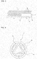
- Fig. 4 is a sectional view of the heat insulator installation area of the twisted tube in the twisted tube heat exchanger according to the embodiment of the present invention. Note that Fig. 4 is a sectional view perpendicular to a length direction of the first pipe 10. In other words, Fig. 4 is a sectional view perpendicular to a pipe axis direction of the first pipe 10. Also, Fig. 4 is a sectional view of a location at which the first pipe 10 and the second pipes 20 are joined together.
- the twisted tube 1 includes the first pipe 10 and the second pipes 20 installed spirally on a periphery of the first pipe 10.
- the first pipe 10 and the second pipes 20 are formed of a material having good thermal conductivity.
- the first pipe 10 and the second pipes 20 are formed, for example, of copper or a copper alloy.
- the first pipe 10 allows the first fluid such as water to flow through the first pipe 10.
- Spiral grooves 13 are formed on the periphery of the first pipe 10, allowing the second pipes 20 to be wound around the spiral grooves 13.
- spiral ridges 14 and spiral valleys 15 are formed alternately on the periphery of the first pipe 10.
- the valleys 15 serve as the grooves 13.
- plural grooves 13 are formed according to the present embodiment. More specifically, three grooves 13 are formed according to the present embodiment. Consequently, as shown in Fig. 4 , a cross-sectional shape of the first pipe 10 having the grooves 13 is triangular.
- the second pipes 20 allow the refrigerant that heats the first fluid to flow through the second pipes 20.
- the second pipes 20 are wound around the grooves 13 on the first pipe 10. Note that plural grooves 13 (more specifically, three grooves 13) are formed according to the present embodiment as described above. Consequently, as many second pipes 20 as grooves are formed are wound around the periphery of the first pipe 10.
- Opposite ends of the second pipes 20 are connected with a pipe used to supply the refrigerant to the second pipes 20 and a pipe through which the refrigerant flows out of the second pipes 20, and thus are not wound around the periphery of the first pipe 10. Consequently, mid-portions of the second pipes 20, that is, parts of the second pipes 20, are wound around a periphery (that is, the grooves 13) of a mid-portion of the first pipe 10. Then, the parts of the second pipes 20 that are wound around the grooves 13 on the first pipe 10 are joined to the first pipe 10 by soldering or another joining method.
- an area in which the first pipe 10 and the second pipes 20 are joined together is defined as a first area 41.
- an area that is located closer to the inlet-side end portion 11 of the first pipe 10 than is the first area 41 and in which the first pipe 10 and the second pipes 20 are not joined together is defined as a second area 42.
- a boundary region between the first area 41 and the second area 42 is defined as a boundary region 43. That is, the boundary region 43 is an outermost portion of the area in which the first pipe 10 and the second pipes 20 are joined together.
- the above-mentioned heat insulator 30 is installed in a certain area including the boundary region 43. Specifically, the heat insulator 30 is wound, covering peripheries of the first pipe 10 and the second pipes 20 in the boundary region 43 and the periphery of the first pipe 10 in the second area 42.
- length of the heat insulator 30 (specifically, axial length of the twisted tube 1) is not particularly limited, but when ease of winding operation, cost of the heat insulator 30, length of an area in which condensation of the twisted tube 1 is expected, and similar other factors are taken into consideration, an appropriate length of the heat insulator 30 is approximately 20 cm from the boundary region 43 toward the second area 42.
- the heat insulator 30 is formed of a material from which components tending to corrode the first pipe 10 or the second pipes 20 are less liable to leach out, for example, of polyethylene foam resin.
- the heat insulator 30 is fixed by being stuck to the twisted tube 1 by adhesive, with the adhesive being applied, for example, to an entire area on one side of the heat insulator 30.
- the adhesive it is advisable to avoid adhesives from which any component (hydrochloric acid, sulfuric acid, acetic acid, or another similar acid) tending to corrode the first pipe 10 or the second pipes 20 leaches out, and, for example, an acrylic adhesive is desirable.
- Fig. 5 is a diagram showing an example of the heat insulator wound around the twisted tube of the twisted tube heat exchanger according to the embodiment of the present invention.
- Fig. 6 is a diagram showing another example of the heat insulator wound around the twisted tube of the twisted tube heat exchanger according to the embodiment of the present invention.
- the heat insulator 30 Before being wound around the twisted tube 1, the heat insulator 30 has, for example, a rectangular shape and has as many holes 31 as second pipes 20 are formed.
- the holes 31 are holes through which the second pipes 20 are inserted.
- the holes 31 have a diameter, for example, substantially equal to an outside diameter of the second pipes 20.
- locations of the holes 31 are not particularly limited, but the holes 31 are formed at an approximate center location in a short-side direction.
- a length L2 of a short side of the heat insulator 30 is dimensioned such that almost the entire peripheries of the first pipe 10 and the second pipes 20 in the boundary region 43 can be covered (see Fig. 4 ).
- Fig. 4 a length L2 of a short side of the heat insulator 30 is dimensioned such that almost the entire peripheries of the first pipe 10 and the second pipes 20 in the boundary region 43 can be covered.
- an end of the heat insulator 30 in a longitudinal direction is placed in the vicinity of a boundary region 43. Consequently, when the area of approximately 20 cm from the boundary region 43 toward the second area 42 is covered by the heat insulator 30, preferably a length L1 of the long side of the heat insulator 30 is also approximately 20 cm. Note that, when a part of the first area 41 closer to the boundary region 43 is also covered by the heat insulator 30, it is advisable to extend the length L1 of the heat insulator 30 by a length over which of the part of the first area 41 is covered.
- a cut is made in the heat insulator 30, running from each hole 31 to an end of the heat insulator 30.
- the second pipes 20 When the second pipes 20 are inserted into the holes 31, by inserting the second pipes 20 from the end of the heat insulator 30 through the cuts 32, the second pipes 20 can be inserted easily into the holes 31.
- a formation direction of the cuts 32 is not particularly limited. The cuts 32 may be made toward a long side as shown in Fig. 5 or the cut 32 may be made toward a short side as shown in Fig. 6 .
- the first fluid flows into the first pipe 10 through the inlet-side end portion 11 of the first pipe 10 of the twisted tube 1.
- the first fluid flows in the first pipe 10 from the second area 42 toward the first area 41. Then, while flowing through the first area 41, the first fluid is heated by the refrigerant flowing through the second pipes 20.
- the heated first fluid flows out of the twisted tube heat exchanger 100 through the outlet-side end portion 12 of the first pipe 10.
- the first fluid flowing through a section of the first pipe 10 that is located in the second area 42 is yet to be heated by the refrigerant, and is the coldest of the first fluid in the first pipe 10. Consequently, the section of the first pipe that is located in the second area is at a lower temperature than ambient temperature, creating an environment liable to cause condensation. Consequently, when the twisted tube heat exchanger 100 is not provided with a heat insulator 30, the section of the first pipe that is located in the second area may cause condensation.
- the second area 42 is an area in which the first pipe 10 and the second pipes 20 are not joined together, and a gap 2 is formed between the first pipe 10 and the second pipes 20 (see Fig. 2 ). Consequently, when the section of the first pipe that is located in the second area causes condensation, in a part of the second area 42 that is close to the boundary region 43 in which the gap 2 is small, condensed water is held, acting as a bridge.
- the refrigerant higher in temperature than the first fluid flows through the second pipes 20 to heat the first fluid in the first pipe 10. That is, the second pipes 20 are higher in temperature than the first pipe 10. Consequently, when condensed water is held, bridging between the first pipe 10 and the second pipes 20, the bridging portion acts as a thermogalvanic cell, causing corrosion of the second pipes 20 located on a high temperature side.
- the heat insulator 30 is wound around a certain area including the boundary region 43. That is, in the twisted tube heat exchanger 100, the heat insulator 30 is wound around the part in which the condensed water bridging between the first pipe 10 and the second pipes 20 would cause corrosion of the second pipes 20 by acting as a thermogalvanic cell. Consequently, the twisted tube heat exchanger 100 according to the present embodiment can inhibit the certain area including the boundary region 43 from cooling ambient air, that is, inhibit the certain area including the boundary region 43 from causing condensation. Thus, the twisted tube heat exchanger 100 according to the present embodiment can inhibit corrosion of the second pipes 20.
- the twisted tube 1 is wound into a coil shape having a plurality of turns. Consequently, when the twisted tube heat exchanger 100 is not provided the heat insulator 30, condensed water is likely to bridge between the section of the first pipe 10 that is located in the second area 42 and a section of the twisted tube 1 that is located above this section. When condensed water acts as a bridge in this way, the bridging portion acts as a thermogalvanic cell, causing corrosion of the second pipe 20 located on the high temperature side.
- the heat insulator 30 is placed between the area in which the heat insulator 30 is wound and the section of the twisted tube 1 that is located above this area.
- the twisted tube heat exchanger 100 according to the present embodiment can inhibit corrosion of the second pipes 20 in the first area 41.
- the twisted tube heat exchanger 100 includes the twisted tube 1, the twisted tube 1 including the first pipe 10 having spiral grooves 13 formed on a periphery of the first pipe 10 and allowing a first fluid to flow through the first pipe 10, and the second pipes 20 having a part wound around the grooves 13 on the first pipe 10 and allowing refrigerant that heats the first fluid to flow through the second pipes 20.
- the twisted tube heat exchanger 100 according to the present embodiment includes the heat insulator 30 wound around a certain area including the boundary region 43 between the first area 41 and the second area 42, covering the peripheries of the first pipe 10 and the second pipes 20 in the boundary region 43 and the periphery of the first pipe 10 in the second area 42.
- the heat insulator 30 is wound around the part in which the condensed water bridging between the first pipe 10 and the second pipes 20 would cause corrosion of the second pipes 20 by acting as a thermogalvanic cell.
- a heat insulator installation method of winding the heat insulator 30 can easily install the heat insulator 30 even on the twisted tube heat exchanger 100 that has a complicated shape. Consequently, the twisted tube heat exchanger 100 according to the present embodiment can inhibit condensed water from bridging between the first pipe 10 and the second pipes 20 and inhibit the bridging portion from acting as a thermogalvanic cell and causing corrosion of the second pipes 20.
- the twisted tube heat exchanger 100 according to the present embodiment only in a part of which the heat insulator 30 is installed, can curb increases in material costs of the twisted tube heat exchanger 100.
- the heat insulator 30 is formed, for example, of polyethylene foam resin. This is because polyethylene foam resin is material from which components tending to corrode the first pipe 10 or the second pipes 20 are less liable to leach out.
- the holes 31 through which the second pipes 20 are inserted and cuts 32 running from the holes 31 to an end of the heat insulator 30 are made in the heat insulator 30, for example.
- the second pipes 20 are inserted into the holes 31, by inserting the second pipes 20 from the end of the heat insulator 30 through the cuts 32, the second pipes 20 can be inserted easily into the holes 31. That is, the heat insulator 30 can be installed more easily.
- the heat insulator 30 is placed between the certain area (around which the heat insulator 30 is wound) and a section of the twisted tube 1 that is located above the certain area. Corrosion of the second pipes 20 can also be inhibited in the section of the twisted tube 1 that is located above the certain area (around which the heat insulator 30 is wound).
Landscapes
- Engineering & Computer Science (AREA)
- Physics & Mathematics (AREA)
- Thermal Sciences (AREA)
- Mechanical Engineering (AREA)
- General Engineering & Computer Science (AREA)
- Heat-Exchange Devices With Radiators And Conduit Assemblies (AREA)
Abstract
Description
- The present invention relates to a twisted tube heat exchanger including a first pipe, and a second pipe installed spirally on a periphery of the first pipe.
- A heat exchanger has been known that includes a first pipe, and a second pipe installed on a periphery of the first pipe and in which a first fluid such as water flowing through the first pipe is heated by refrigerant flowing through the second pipe (see, for example, Patent Literature 1). In the heat exchanger described in
Patent Literature 1, the second pipe is placed along a length direction of the first pipe. In other words, in the heat exchanger described inPatent Literature 1, the first pipe and the second pipe are arranged in parallel. Besides, in the heat exchanger described inPatent Literature 1, peripheries of the first pipe and the second pipe are covered with a resin layer and the second pipe is placed in close contact with the first pipe. The resin layer covering the peripheries of the first pipe and the second pipe also serves as a heat insulator. Also, the resin layer is provided on the peripheries of the first pipe and the second pipe by extrusion process. - Also, as a heat exchanger configured to heat the first fluid such as water flowing through the first pipe with refrigerant flowing through the second pipe, a twisted tube heat exchanger has been proposed. The twisted tube heat exchanger includes a first pipe with a spiral groove formed on a periphery and a second pipe wound around the groove on the first pipe. That is, the second pipe is installed spirally on the periphery of the first pipe.
- Patent Literature 1: Japanese Unexamined Patent Application Publication No.
2004-347178 - In the heat exchanger described in
Patent Literature 1, the resin layer serving as a heat insulator is formed by extrusion process. That is, the heat exchanger described inPatent Literature 1 is configured such that the heat insulator is installed on the entire heat exchanger. Thus, a configuration in which a heat insulator is installed in such a way as described inPatent Literature 1 has a problem of increased material costs of the heat exchanger. - Also, the twisted tube heat exchanger has a complicated shape in which the second pipe is installed spirally on the periphery of the first pipe. Consequently, it is practically impossible to form a resin layer on the peripheries of the twisted tube heat exchanger by extrusion process. Thus, the conventional twisted tube heat exchanger has a problem in that the second pipe is corroded because a heat insulating layer cannot be formed on the peripheries.
- Specifically, opposite ends of the second pipe are connected with a pipe used to supply refrigerant to the second pipe and a pipe through which the refrigerant flows out of the second pipe, and thus are not wound around the periphery of the first pipe. Consequently, a mid-portion of the second pipe is wound around a periphery of a mid-portion of the first pipe. Then, the part of the second pipe that is wound around the periphery of the first pipe is joined to the first pipe by soldering or another joining method. Hereinafter, an area in which the first pipe and the second pipe are joined together will be referred to as a first area while an area that is located closer to an end side of the first pipe than is the first area and an area in which the first pipe and the second pipe are not joined together will be referred to as a second area.
- In the twisted tube heat exchanger, which is configured as described above, the first fluid flowing into the first pipe flows first in the second area. Subsequently, the first fluid in the first pipe flows into the first area and is heated by the refrigerant flowing through the second pipe. That is, the first fluid flowing through a section of the first pipe that is located in the second area is yet to be heated by the refrigerant, and thus remains at a low temperature. Consequently, the section of the first pipe that is located in the second area is at a lower temperature than ambient temperature and tends to cause condensation. Also, in the second area, in which the first pipe and the second pipe are not joined together, a gap is formed between the first pipe and the second pipe. Consequently, when condensation occurs, in the second area in which the gap between the first pipe and the second pipe is small, that is, in a part of the second area that is close to a border with the first area, condensed water is held, bridging between the first pipe and the second pipe. Here, the refrigerant higher in temperature than the first fluid flows through the second pipe to heat the first fluid in the first pipe. That is, the second pipe is higher in temperature than the first pipe. Consequently, when condensed water is held, bridging between the first pipe and the second pipe, the bridging portion acts as a thermogalvanic cell, causing corrosion of the second pipe located on a high temperature side.
- The present invention has been made to solve the above problem and has an object to provide a twisted tube heat exchanger that can inhibit corrosion of the second pipe and curb increases in material costs.
- A twisted tube heat exchanger according to an embodiment of the present invention includes a twisted tube, and a heat insulator. The twisted tube includes a first pipe having a spiral groove formed on a periphery of the first pipe and allowing a first fluid to flow through the first pipe, and a second pipe having a part wound around the spiral groove on the first pipe and allowing refrigerant that heats the first fluid to flow through the second pipe. An area in which the first pipe and the second pipe are joined together is defined as a first area, and an area that is located closer to an end side of the first pipe than is the first area and in which the first pipe and the second pipe are not joined together is defined as a second area. The heat insulator is wound around a certain area including a boundary region between the first area and the second area, covering peripheries of the first pipe and the second pipe in the boundary region and a periphery of the first pipe in the second area.
- The twisted tube heat exchanger according to an embodiment of the present invention can be used as a configuration in which the first fluid flows from the second area to the first area. In the twisted tube heat exchanger according to the embodiment of the present invention, the heat insulator is wound, covering the peripheries of the first pipe and the second pipe in the boundary region between the first area and the second area as well as the periphery of the first pipe in the second area. That is, in the twisted tube heat exchanger according to the embodiment of the present invention, the heat insulator is wound around a portion in which condensed water bridging between the first pipe and the second pipe acts as a thermogalvanic cell, causing corrosion of the second pipe. Unlike a heat insulator installation method that uses an extrusion process, a heat insulator installation method of winding a heat insulator can easily install the heat insulator even on the twisted tube heat exchanger that has a complicated shape. Consequently, the twisted tube heat exchanger according to the embodiment of the present invention can inhibit condensed water from bridging between the first pipe and the second pipe and inhibit the bridging portion from acting as a thermogalvanic cell and causing corrosion of the second pipe. Also, the twisted tube heat exchanger according to the embodiment of the present invention, only in a part of which the heat insulator is installed, can curb increases in material costs of the twisted tube heat exchanger.
-
- [
Fig. 1] Fig. 1 is a perspective view showing a twisted tube heat exchanger according to an embodiment of the present invention. - [
Fig. 2] Fig. 2 is an enlarged view of a principal part showing a vicinity of a heat insulator installation area of a twisted tube in the twisted tube heat exchanger according to the embodiment of the present invention, where a heat insulator is yet to be installed. - [
Fig. 3] Fig. 3 is an enlarged view of a principal part showing a vicinity of the heat insulator installation area of the twisted tube in the twisted tube heat exchanger according to the embodiment of the present invention, where a heat insulator has been installed. - [
Fig. 4] Fig. 4 is a sectional view of the heat insulator installation area of the twisted tube in the twisted tube heat exchanger according to the embodiment of the present invention. - [
Fig. 5] Fig. 5 is a diagram showing an example of the heat insulator wound around the twisted tube of the twisted tube heat exchanger according to the embodiment of the present invention. - [
Fig. 6] Fig. 6 is a diagram showing another example of the heat insulator wound around the twisted tube of the twisted tube heat exchanger according to the embodiment of the present invention. -
Fig. 1 is a perspective view showing a twisted tube heat exchanger according to an embodiment of the present invention. - The twisted
tube heat exchanger 100 includes atwisted tube 1. Although details of thetwisted tube 1 will be described later, thetwisted tube 1 includes afirst pipe 10 through which a first fluid such as water flows andsecond pipes 20 through which refrigerant that heats the first fluid flows, as described later (seeFigs. 2 and3 described later). Also, in the twistedtube heat exchanger 100 according to the present embodiment, aheat insulator 30 is wound around a part of thetwisted tube 1. Note that the twistedtube heat exchanger 100 according to the present embodiment uses a long twisted tube 1 (long in length). Consequently, in the twistedtube heat exchanger 100 according to the present embodiment, thetwisted tube 1 is wound into a coil shape having a plurality of turns. A height of the coil shape portion and the number of the turns of the coil shape portion can be determined appropriately depending on a length of thetwisted tube 1. - The twisted
tube heat exchanger 100 is used, for example, as a water refrigerant heat exchanger for a heat pump water heater. In this case, water serving as the first fluid is heated by the twistedtube heat exchanger 100. Specifically, the water flows into thetwisted tube 1 through an inlet-side end portion 11 of thetwisted tube 1. More specifically, the water flows into thefirst pipe 10 through the inlet-side end portion 11 of thefirst pipe 10 of thetwisted tube 1. Then, the water flowing into thefirst pipe 10 is heated to become hot water by the refrigerant flowing through thesecond pipes 20, and then flows out through an outlet-side end portion 12. - Next, details of the
twisted tube 1 according to the present embodiment will be described. -
Fig. 2 is an enlarged view of a principal part showing a vicinity of a heat insulator installation area of the twisted tube in the twisted tube heat exchanger according to the embodiment of the present invention, where a heat insulator is yet to be installed.Fig. 3 is an enlarged view of a principal part showing a vicinity of the heat insulator installation area of the twisted tube in the twisted tube heat exchanger according to the embodiment of the present invention, where a heat insulator has been installed. Also,Fig. 4 is a sectional view of the heat insulator installation area of the twisted tube in the twisted tube heat exchanger according to the embodiment of the present invention. Note thatFig. 4 is a sectional view perpendicular to a length direction of thefirst pipe 10. In other words,Fig. 4 is a sectional view perpendicular to a pipe axis direction of thefirst pipe 10. Also,Fig. 4 is a sectional view of a location at which thefirst pipe 10 and thesecond pipes 20 are joined together. - The
twisted tube 1 includes thefirst pipe 10 and thesecond pipes 20 installed spirally on a periphery of thefirst pipe 10. Thefirst pipe 10 and thesecond pipes 20 are formed of a material having good thermal conductivity. According to the present embodiment, thefirst pipe 10 and thesecond pipes 20 are formed, for example, of copper or a copper alloy. - As described above, the
first pipe 10 allows the first fluid such as water to flow through thefirst pipe 10. Spiral grooves 13 are formed on the periphery of thefirst pipe 10, allowing thesecond pipes 20 to be wound around the spiral grooves 13. Specifically, according to the present embodiment,spiral ridges 14 and spiral valleys 15 are formed alternately on the periphery of thefirst pipe 10. The valleys 15 serve as the grooves 13. Note that plural grooves 13 are formed according to the present embodiment. More specifically, three grooves 13 are formed according to the present embodiment. Consequently, as shown inFig. 4 , a cross-sectional shape of thefirst pipe 10 having the grooves 13 is triangular. This is because three sides are formed when thefirst pipe 10 is formed by twisting a circular pipe to form three grooves around thefirst pipe 10. Consequently, when four grooves 13 are formed on thefirst pipe 10, a cross-sectional shape of thefirst pipe 10 having the grooves 13 is quadrangular. - As described above, the
second pipes 20 allow the refrigerant that heats the first fluid to flow through thesecond pipes 20. Thesecond pipes 20 are wound around the grooves 13 on thefirst pipe 10. Note that plural grooves 13 (more specifically, three grooves 13) are formed according to the present embodiment as described above. Consequently, as manysecond pipes 20 as grooves are formed are wound around the periphery of thefirst pipe 10. - Opposite ends of the
second pipes 20 are connected with a pipe used to supply the refrigerant to thesecond pipes 20 and a pipe through which the refrigerant flows out of thesecond pipes 20, and thus are not wound around the periphery of thefirst pipe 10. Consequently, mid-portions of thesecond pipes 20, that is, parts of thesecond pipes 20, are wound around a periphery (that is, the grooves 13) of a mid-portion of thefirst pipe 10. Then, the parts of thesecond pipes 20 that are wound around the grooves 13 on thefirst pipe 10 are joined to thefirst pipe 10 by soldering or another joining method. - Note that, according to the present embodiment, an area in which the
first pipe 10 and thesecond pipes 20 are joined together is defined as afirst area 41. Also, an area that is located closer to the inlet-side end portion 11 of thefirst pipe 10 than is thefirst area 41 and in which thefirst pipe 10 and thesecond pipes 20 are not joined together is defined as asecond area 42. Also, a boundary region between thefirst area 41 and thesecond area 42 is defined as aboundary region 43. That is, theboundary region 43 is an outermost portion of the area in which thefirst pipe 10 and thesecond pipes 20 are joined together. - As shown in
Fig. 3 , in thetwisted tube 1 according to the present embodiment, the above-mentionedheat insulator 30 is installed in a certain area including theboundary region 43. Specifically, theheat insulator 30 is wound, covering peripheries of thefirst pipe 10 and thesecond pipes 20 in theboundary region 43 and the periphery of thefirst pipe 10 in thesecond area 42. Note that length of the heat insulator 30 (specifically, axial length of the twisted tube 1) is not particularly limited, but when ease of winding operation, cost of theheat insulator 30, length of an area in which condensation of thetwisted tube 1 is expected, and similar other factors are taken into consideration, an appropriate length of theheat insulator 30 is approximately 20 cm from theboundary region 43 toward thesecond area 42. Also, preferably theheat insulator 30 is formed of a material from which components tending to corrode thefirst pipe 10 or thesecond pipes 20 are less liable to leach out, for example, of polyethylene foam resin. - The
heat insulator 30 is fixed by being stuck to thetwisted tube 1 by adhesive, with the adhesive being applied, for example, to an entire area on one side of theheat insulator 30. When theheat insulator 30 is fixed in this way, regarding the adhesive to be used, it is advisable to avoid adhesives from which any component (hydrochloric acid, sulfuric acid, acetic acid, or another similar acid) tending to corrode thefirst pipe 10 or thesecond pipes 20 leaches out, and, for example, an acrylic adhesive is desirable. -
Fig. 5 is a diagram showing an example of the heat insulator wound around the twisted tube of the twisted tube heat exchanger according to the embodiment of the present invention. Also,Fig. 6 is a diagram showing another example of the heat insulator wound around the twisted tube of the twisted tube heat exchanger according to the embodiment of the present invention. - Before being wound around the
twisted tube 1, theheat insulator 30 has, for example, a rectangular shape and has asmany holes 31 assecond pipes 20 are formed. Theholes 31 are holes through which thesecond pipes 20 are inserted. Theholes 31 have a diameter, for example, substantially equal to an outside diameter of thesecond pipes 20. Note that locations of theholes 31 are not particularly limited, but theholes 31 are formed at an approximate center location in a short-side direction. Also, preferably a length L2 of a short side of theheat insulator 30 is dimensioned such that almost the entire peripheries of thefirst pipe 10 and thesecond pipes 20 in theboundary region 43 can be covered (seeFig. 4 ). Also, according to the present embodiment, as shown inFig. 3 , an end of theheat insulator 30 in a longitudinal direction is placed in the vicinity of aboundary region 43. Consequently, when the area of approximately 20 cm from theboundary region 43 toward thesecond area 42 is covered by theheat insulator 30, preferably a length L1 of the long side of theheat insulator 30 is also approximately 20 cm. Note that, when a part of thefirst area 41 closer to theboundary region 43 is also covered by theheat insulator 30, it is advisable to extend the length L1 of theheat insulator 30 by a length over which of the part of thefirst area 41 is covered. - Also, a cut is made in the
heat insulator 30, running from eachhole 31 to an end of theheat insulator 30. When thesecond pipes 20 are inserted into theholes 31, by inserting thesecond pipes 20 from the end of theheat insulator 30 through thecuts 32, thesecond pipes 20 can be inserted easily into theholes 31. Note that a formation direction of thecuts 32 is not particularly limited. Thecuts 32 may be made toward a long side as shown inFig. 5 or thecut 32 may be made toward a short side as shown inFig. 6 . - Next, an operation of heating the first fluid in the twisted
tube heat exchanger 100 according to the present embodiment will be described. - The first fluid flows into the
first pipe 10 through the inlet-side end portion 11 of thefirst pipe 10 of thetwisted tube 1. The first fluid flows in thefirst pipe 10 from thesecond area 42 toward thefirst area 41. Then, while flowing through thefirst area 41, the first fluid is heated by the refrigerant flowing through thesecond pipes 20. The heated first fluid flows out of the twistedtube heat exchanger 100 through the outlet-side end portion 12 of thefirst pipe 10. - Here, the first fluid flowing through a section of the
first pipe 10 that is located in thesecond area 42 is yet to be heated by the refrigerant, and is the coldest of the first fluid in thefirst pipe 10. Consequently, the section of the first pipe that is located in the second area is at a lower temperature than ambient temperature, creating an environment liable to cause condensation. Consequently, when the twistedtube heat exchanger 100 is not provided with aheat insulator 30, the section of the first pipe that is located in the second area may cause condensation. - The
second area 42 is an area in which thefirst pipe 10 and thesecond pipes 20 are not joined together, and a gap 2 is formed between thefirst pipe 10 and the second pipes 20 (seeFig. 2 ). Consequently, when the section of the first pipe that is located in the second area causes condensation, in a part of thesecond area 42 that is close to theboundary region 43 in which the gap 2 is small, condensed water is held, acting as a bridge. Here, the refrigerant higher in temperature than the first fluid flows through thesecond pipes 20 to heat the first fluid in thefirst pipe 10. That is, thesecond pipes 20 are higher in temperature than thefirst pipe 10. Consequently, when condensed water is held, bridging between thefirst pipe 10 and thesecond pipes 20, the bridging portion acts as a thermogalvanic cell, causing corrosion of thesecond pipes 20 located on a high temperature side. - However, in the twisted
tube heat exchanger 100 according to the present embodiment, theheat insulator 30 is wound around a certain area including theboundary region 43. That is, in the twistedtube heat exchanger 100, theheat insulator 30 is wound around the part in which the condensed water bridging between thefirst pipe 10 and thesecond pipes 20 would cause corrosion of thesecond pipes 20 by acting as a thermogalvanic cell. Consequently, the twistedtube heat exchanger 100 according to the present embodiment can inhibit the certain area including theboundary region 43 from cooling ambient air, that is, inhibit the certain area including theboundary region 43 from causing condensation. Thus, the twistedtube heat exchanger 100 according to the present embodiment can inhibit corrosion of thesecond pipes 20. - Note that, as described above, in the twisted
tube heat exchanger 100 according to the present embodiment, thetwisted tube 1 is wound into a coil shape having a plurality of turns. Consequently, when the twistedtube heat exchanger 100 is not provided theheat insulator 30, condensed water is likely to bridge between the section of thefirst pipe 10 that is located in thesecond area 42 and a section of thetwisted tube 1 that is located above this section. When condensed water acts as a bridge in this way, the bridging portion acts as a thermogalvanic cell, causing corrosion of thesecond pipe 20 located on the high temperature side. However, as shown inFigs. 1 and3 , in the twistedtube heat exchanger 100 according to the present embodiment, theheat insulator 30 is placed between the area in which theheat insulator 30 is wound and the section of thetwisted tube 1 that is located above this area. Thus, the twistedtube heat exchanger 100 according to the present embodiment can inhibit corrosion of thesecond pipes 20 in thefirst area 41. - As described above, the twisted
tube heat exchanger 100 according to the present embodiment includes thetwisted tube 1, thetwisted tube 1 including thefirst pipe 10 having spiral grooves 13 formed on a periphery of thefirst pipe 10 and allowing a first fluid to flow through thefirst pipe 10, and thesecond pipes 20 having a part wound around the grooves 13 on thefirst pipe 10 and allowing refrigerant that heats the first fluid to flow through thesecond pipes 20. Also, the twistedtube heat exchanger 100 according to the present embodiment includes theheat insulator 30 wound around a certain area including theboundary region 43 between thefirst area 41 and thesecond area 42, covering the peripheries of thefirst pipe 10 and thesecond pipes 20 in theboundary region 43 and the periphery of thefirst pipe 10 in thesecond area 42. - In the twisted
tube heat exchanger 100 according to the present embodiment, theheat insulator 30 is wound around the part in which the condensed water bridging between thefirst pipe 10 and thesecond pipes 20 would cause corrosion of thesecond pipes 20 by acting as a thermogalvanic cell. Unlike a heat insulator installation method that uses an extrusion process, a heat insulator installation method of winding theheat insulator 30 can easily install theheat insulator 30 even on the twistedtube heat exchanger 100 that has a complicated shape. Consequently, the twistedtube heat exchanger 100 according to the present embodiment can inhibit condensed water from bridging between thefirst pipe 10 and thesecond pipes 20 and inhibit the bridging portion from acting as a thermogalvanic cell and causing corrosion of thesecond pipes 20. Also, the twistedtube heat exchanger 100 according to the present embodiment, only in a part of which theheat insulator 30 is installed, can curb increases in material costs of the twistedtube heat exchanger 100. - Note that the
heat insulator 30 is formed, for example, of polyethylene foam resin. This is because polyethylene foam resin is material from which components tending to corrode thefirst pipe 10 or thesecond pipes 20 are less liable to leach out. - Also, the
holes 31 through which thesecond pipes 20 are inserted andcuts 32 running from theholes 31 to an end of theheat insulator 30 are made in theheat insulator 30, for example. When thesecond pipes 20 are inserted into theholes 31, by inserting thesecond pipes 20 from the end of theheat insulator 30 through thecuts 32, thesecond pipes 20 can be inserted easily into theholes 31. That is, theheat insulator 30 can be installed more easily. - Also, when the
twisted tube 1 is wound into a coil shape having a plurality of turns, theheat insulator 30 is placed between the certain area (around which theheat insulator 30 is wound) and a section of thetwisted tube 1 that is located above the certain area. Corrosion of thesecond pipes 20 can also be inhibited in the section of thetwisted tube 1 that is located above the certain area (around which theheat insulator 30 is wound). -
- 1 twisted tube 2
gap 10first pipe 11 inlet-side end portion12 outlet-side end portion 13groove 14 ridge 15valley 20second pipe 30heat insulator 31hole 32 cut 41first area 42second area 43boundary region 100 twisted tube heat exchanger
Claims (5)
- A twisted tube heat exchanger comprising:a twisted tube; anda heat insulator,the twisted tube includinga first pipe having a spiral groove formed on a periphery of the first pipe and allowing a first fluid to flow through the first pipe, anda second pipe having a part wound around the spiral groove on the first pipe and allowing refrigerant that heats the first fluid to flow through the second pipe,an area in which the first pipe and the second pipe are joined together being defined as a first area,an area that is located closer to an end side of the first pipe than is the first area and in which the first pipe and the second pipe are not joined together being defined as a second area,the heat insulator being wound around a certain area including a boundary region between the first area and the second area, covering peripheries of the first pipe and the second pipe in the boundary region and a periphery of the first pipe in the second area.
- The twisted tube heat exchanger of claim 1, wherein the heat insulator is formed of polyethylene foam resin.
- The twisted tube heat exchanger of claim 1 or 2, wherein a hole through which the second pipe is inserted and a cut running from the hole to an end of the heat insulator are made in the heat insulator.
- The twisted tube heat exchanger of any one of claims 1 to 3, wherein
the twisted tube is wound into a coil shape having a plurality of turns, and
the heat insulator is placed between the certain area and a section of the twisted tube that is located above the certain area. - The twisted tube heat exchanger of any one of claims 1 to 4, wherein the first fluid flows from the second area toward the first area.
Applications Claiming Priority (1)
| Application Number | Priority Date | Filing Date | Title |
|---|---|---|---|
| PCT/JP2017/001447 WO2018134899A1 (en) | 2017-01-18 | 2017-01-18 | Twisted pipe heat exchanger |
Publications (3)
| Publication Number | Publication Date |
|---|---|
| EP3370026A4 EP3370026A4 (en) | 2018-09-05 |
| EP3370026A1 true EP3370026A1 (en) | 2018-09-05 |
| EP3370026B1 EP3370026B1 (en) | 2019-06-05 |
Family
ID=62907939
Family Applications (1)
| Application Number | Title | Priority Date | Filing Date |
|---|---|---|---|
| EP17797221.3A Active EP3370026B1 (en) | 2017-01-18 | 2017-01-18 | Twisted pipe heat exchanger |
Country Status (4)
| Country | Link |
|---|---|
| EP (1) | EP3370026B1 (en) |
| JP (1) | JP6682017B2 (en) |
| CN (1) | CN208765538U (en) |
| WO (1) | WO2018134899A1 (en) |
Families Citing this family (1)
| Publication number | Priority date | Publication date | Assignee | Title |
|---|---|---|---|---|
| CN116164559B (en) * | 2023-04-07 | 2025-10-14 | 中国科学院高能物理研究所 | A compact negative pressure low temperature heat exchanger |
Family Cites Families (8)
| Publication number | Priority date | Publication date | Assignee | Title |
|---|---|---|---|---|
| JPS5580685U (en) * | 1978-11-28 | 1980-06-03 | ||
| JPS5724870U (en) * | 1980-07-18 | 1982-02-09 | ||
| JPS6234662U (en) * | 1985-08-16 | 1987-02-28 | ||
| JP2004347178A (en) | 2003-05-20 | 2004-12-09 | Furukawa Electric Co Ltd:The | Heat exchanger |
| JP2005164166A (en) * | 2003-12-04 | 2005-06-23 | Kobelco & Materials Copper Tube Inc | Heat exchanger |
| JP4437487B2 (en) * | 2006-10-13 | 2010-03-24 | 三菱電機株式会社 | Twisted tube heat exchanger and heat pump water heater |
| JP5255236B2 (en) * | 2007-06-25 | 2013-08-07 | 古河電気工業株式会社 | Heat exchanger and heat exchange system |
| EP3009767B1 (en) * | 2013-06-13 | 2020-12-09 | Mitsubishi Electric Corporation | Heat pump device |
-
2017
- 2017-01-18 CN CN201790000282.2U patent/CN208765538U/en not_active Expired - Fee Related
- 2017-01-18 EP EP17797221.3A patent/EP3370026B1/en active Active
- 2017-01-18 WO PCT/JP2017/001447 patent/WO2018134899A1/en not_active Ceased
- 2017-01-18 JP JP2018562771A patent/JP6682017B2/en not_active Expired - Fee Related
Also Published As
| Publication number | Publication date |
|---|---|
| CN208765538U (en) | 2019-04-19 |
| EP3370026A4 (en) | 2018-09-05 |
| JP6682017B2 (en) | 2020-04-15 |
| WO2018134899A1 (en) | 2018-07-26 |
| JPWO2018134899A1 (en) | 2019-04-04 |
| EP3370026B1 (en) | 2019-06-05 |
Similar Documents
| Publication | Publication Date | Title |
|---|---|---|
| EP2594869B1 (en) | Air conditioner | |
| CN102072598B (en) | Air-returning pipe component and preparation method thereof | |
| EP3370026B1 (en) | Twisted pipe heat exchanger | |
| US20230113674A1 (en) | Sheathed fiberglass heater wire | |
| JP6991567B2 (en) | Double tube heat exchanger | |
| JP2008121934A (en) | Plate fin tube heat exchanger and its manufacturing method | |
| EP2813792B1 (en) | Twisted tube heat exchanger and method for manufacturing twisted tube heat exchanger | |
| US4349950A (en) | Heat exchanger and method of making | |
| JP4207895B2 (en) | Heater | |
| RU2502931C2 (en) | Double-pipe heat exchanger | |
| JP2008249163A (en) | Heat exchanger for hot water supply | |
| JP2009241145A (en) | Method of manufacturing double pipe having bent part and double pipe having bent part | |
| CN107850358A (en) | Heat exchanger and refrigerating circulatory device | |
| CN204923995U (en) | Can prevent microchannel heat exchanger of flat pipe of external damage | |
| US7145932B2 (en) | Electric furnace | |
| RU62694U1 (en) | HEAT EXCHANGE ELEMENT | |
| KR101375121B1 (en) | Hot water supply pipe assembly for heating | |
| RU2806392C2 (en) | Anti-icing device | |
| JP2014181827A (en) | Heat exchanger | |
| JP5794952B2 (en) | Twisted tube heat exchanger | |
| WO2019058471A1 (en) | Heat exchanger, air conditioner outdoor unit, and air conditioner | |
| JP2010127496A (en) | Heat exchanger | |
| JP2005098612A (en) | Heat exchanger and manufacturing method thereof | |
| JP6486225B2 (en) | Heat exchanger | |
| CN118974506A (en) | Air conditioner |
Legal Events
| Date | Code | Title | Description |
|---|---|---|---|
| STAA | Information on the status of an ep patent application or granted ep patent |
Free format text: STATUS: UNKNOWN |
|
| STAA | Information on the status of an ep patent application or granted ep patent |
Free format text: STATUS: THE INTERNATIONAL PUBLICATION HAS BEEN MADE |
|
| PUAI | Public reference made under article 153(3) epc to a published international application that has entered the european phase |
Free format text: ORIGINAL CODE: 0009012 |
|
| STAA | Information on the status of an ep patent application or granted ep patent |
Free format text: STATUS: REQUEST FOR EXAMINATION WAS MADE |
|
| 17P | Request for examination filed |
Effective date: 20171121 |
|
| A4 | Supplementary search report drawn up and despatched |
Effective date: 20180702 |
|
| AK | Designated contracting states |
Kind code of ref document: A1 Designated state(s): AL AT BE BG CH CY CZ DE DK EE ES FI FR GB GR HR HU IE IS IT LI LT LU LV MC MK MT NL NO PL PT RO RS SE SI SK SM TR |
|
| AX | Request for extension of the european patent |
Extension state: BA ME |
|
| RIN1 | Information on inventor provided before grant (corrected) |
Inventor name: YAMAGUCHI, KOSUKE Inventor name: AZUMA, MASAAKI |
|
| GRAP | Despatch of communication of intention to grant a patent |
Free format text: ORIGINAL CODE: EPIDOSNIGR1 |
|
| STAA | Information on the status of an ep patent application or granted ep patent |
Free format text: STATUS: GRANT OF PATENT IS INTENDED |
|
| INTG | Intention to grant announced |
Effective date: 20181210 |
|
| GRAS | Grant fee paid |
Free format text: ORIGINAL CODE: EPIDOSNIGR3 |
|
| GRAA | (expected) grant |
Free format text: ORIGINAL CODE: 0009210 |
|
| STAA | Information on the status of an ep patent application or granted ep patent |
Free format text: STATUS: THE PATENT HAS BEEN GRANTED |
|
| AK | Designated contracting states |
Kind code of ref document: B1 Designated state(s): AL AT BE BG CH CY CZ DE DK EE ES FI FR GB GR HR HU IE IS IT LI LT LU LV MC MK MT NL NO PL PT RO RS SE SI SK SM TR |
|
| DAV | Request for validation of the european patent (deleted) | ||
| DAX | Request for extension of the european patent (deleted) | ||
| REG | Reference to a national code |
Ref country code: GB Ref legal event code: FG4D |
|
| REG | Reference to a national code |
Ref country code: CH Ref legal event code: EP |
|
| REG | Reference to a national code |
Ref country code: AT Ref legal event code: REF Ref document number: 1140441 Country of ref document: AT Kind code of ref document: T Effective date: 20190615 |
|
| REG | Reference to a national code |
Ref country code: IE Ref legal event code: FG4D |
|
| REG | Reference to a national code |
Ref country code: DE Ref legal event code: R096 Ref document number: 602017004348 Country of ref document: DE |
|
| REG | Reference to a national code |
Ref country code: NL Ref legal event code: MP Effective date: 20190605 |
|
| REG | Reference to a national code |
Ref country code: LT Ref legal event code: MG4D |
|
| PG25 | Lapsed in a contracting state [announced via postgrant information from national office to epo] |
Ref country code: ES Free format text: LAPSE BECAUSE OF FAILURE TO SUBMIT A TRANSLATION OF THE DESCRIPTION OR TO PAY THE FEE WITHIN THE PRESCRIBED TIME-LIMIT Effective date: 20190605 Ref country code: FI Free format text: LAPSE BECAUSE OF FAILURE TO SUBMIT A TRANSLATION OF THE DESCRIPTION OR TO PAY THE FEE WITHIN THE PRESCRIBED TIME-LIMIT Effective date: 20190605 Ref country code: AL Free format text: LAPSE BECAUSE OF FAILURE TO SUBMIT A TRANSLATION OF THE DESCRIPTION OR TO PAY THE FEE WITHIN THE PRESCRIBED TIME-LIMIT Effective date: 20190605 Ref country code: SE Free format text: LAPSE BECAUSE OF FAILURE TO SUBMIT A TRANSLATION OF THE DESCRIPTION OR TO PAY THE FEE WITHIN THE PRESCRIBED TIME-LIMIT Effective date: 20190605 Ref country code: NO Free format text: LAPSE BECAUSE OF FAILURE TO SUBMIT A TRANSLATION OF THE DESCRIPTION OR TO PAY THE FEE WITHIN THE PRESCRIBED TIME-LIMIT Effective date: 20190905 Ref country code: LT Free format text: LAPSE BECAUSE OF FAILURE TO SUBMIT A TRANSLATION OF THE DESCRIPTION OR TO PAY THE FEE WITHIN THE PRESCRIBED TIME-LIMIT Effective date: 20190605 Ref country code: HR Free format text: LAPSE BECAUSE OF FAILURE TO SUBMIT A TRANSLATION OF THE DESCRIPTION OR TO PAY THE FEE WITHIN THE PRESCRIBED TIME-LIMIT Effective date: 20190605 |
|
| PG25 | Lapsed in a contracting state [announced via postgrant information from national office to epo] |
Ref country code: LV Free format text: LAPSE BECAUSE OF FAILURE TO SUBMIT A TRANSLATION OF THE DESCRIPTION OR TO PAY THE FEE WITHIN THE PRESCRIBED TIME-LIMIT Effective date: 20190605 Ref country code: RS Free format text: LAPSE BECAUSE OF FAILURE TO SUBMIT A TRANSLATION OF THE DESCRIPTION OR TO PAY THE FEE WITHIN THE PRESCRIBED TIME-LIMIT Effective date: 20190605 Ref country code: BG Free format text: LAPSE BECAUSE OF FAILURE TO SUBMIT A TRANSLATION OF THE DESCRIPTION OR TO PAY THE FEE WITHIN THE PRESCRIBED TIME-LIMIT Effective date: 20190905 Ref country code: GR Free format text: LAPSE BECAUSE OF FAILURE TO SUBMIT A TRANSLATION OF THE DESCRIPTION OR TO PAY THE FEE WITHIN THE PRESCRIBED TIME-LIMIT Effective date: 20190906 |
|
| REG | Reference to a national code |
Ref country code: AT Ref legal event code: MK05 Ref document number: 1140441 Country of ref document: AT Kind code of ref document: T Effective date: 20190605 |
|
| PG25 | Lapsed in a contracting state [announced via postgrant information from national office to epo] |
Ref country code: PT Free format text: LAPSE BECAUSE OF FAILURE TO SUBMIT A TRANSLATION OF THE DESCRIPTION OR TO PAY THE FEE WITHIN THE PRESCRIBED TIME-LIMIT Effective date: 20191007 Ref country code: AT Free format text: LAPSE BECAUSE OF FAILURE TO SUBMIT A TRANSLATION OF THE DESCRIPTION OR TO PAY THE FEE WITHIN THE PRESCRIBED TIME-LIMIT Effective date: 20190605 Ref country code: SK Free format text: LAPSE BECAUSE OF FAILURE TO SUBMIT A TRANSLATION OF THE DESCRIPTION OR TO PAY THE FEE WITHIN THE PRESCRIBED TIME-LIMIT Effective date: 20190605 Ref country code: EE Free format text: LAPSE BECAUSE OF FAILURE TO SUBMIT A TRANSLATION OF THE DESCRIPTION OR TO PAY THE FEE WITHIN THE PRESCRIBED TIME-LIMIT Effective date: 20190605 Ref country code: NL Free format text: LAPSE BECAUSE OF FAILURE TO SUBMIT A TRANSLATION OF THE DESCRIPTION OR TO PAY THE FEE WITHIN THE PRESCRIBED TIME-LIMIT Effective date: 20190605 Ref country code: CZ Free format text: LAPSE BECAUSE OF FAILURE TO SUBMIT A TRANSLATION OF THE DESCRIPTION OR TO PAY THE FEE WITHIN THE PRESCRIBED TIME-LIMIT Effective date: 20190605 Ref country code: RO Free format text: LAPSE BECAUSE OF FAILURE TO SUBMIT A TRANSLATION OF THE DESCRIPTION OR TO PAY THE FEE WITHIN THE PRESCRIBED TIME-LIMIT Effective date: 20190605 |
|
| PG25 | Lapsed in a contracting state [announced via postgrant information from national office to epo] |
Ref country code: SM Free format text: LAPSE BECAUSE OF FAILURE TO SUBMIT A TRANSLATION OF THE DESCRIPTION OR TO PAY THE FEE WITHIN THE PRESCRIBED TIME-LIMIT Effective date: 20190605 Ref country code: IS Free format text: LAPSE BECAUSE OF FAILURE TO SUBMIT A TRANSLATION OF THE DESCRIPTION OR TO PAY THE FEE WITHIN THE PRESCRIBED TIME-LIMIT Effective date: 20191005 Ref country code: IT Free format text: LAPSE BECAUSE OF FAILURE TO SUBMIT A TRANSLATION OF THE DESCRIPTION OR TO PAY THE FEE WITHIN THE PRESCRIBED TIME-LIMIT Effective date: 20190605 |
|
| REG | Reference to a national code |
Ref country code: DE Ref legal event code: R097 Ref document number: 602017004348 Country of ref document: DE |
|
| PG25 | Lapsed in a contracting state [announced via postgrant information from national office to epo] |
Ref country code: TR Free format text: LAPSE BECAUSE OF FAILURE TO SUBMIT A TRANSLATION OF THE DESCRIPTION OR TO PAY THE FEE WITHIN THE PRESCRIBED TIME-LIMIT Effective date: 20190605 |
|
| PLBE | No opposition filed within time limit |
Free format text: ORIGINAL CODE: 0009261 |
|
| STAA | Information on the status of an ep patent application or granted ep patent |
Free format text: STATUS: NO OPPOSITION FILED WITHIN TIME LIMIT |
|
| PG25 | Lapsed in a contracting state [announced via postgrant information from national office to epo] |
Ref country code: PL Free format text: LAPSE BECAUSE OF FAILURE TO SUBMIT A TRANSLATION OF THE DESCRIPTION OR TO PAY THE FEE WITHIN THE PRESCRIBED TIME-LIMIT Effective date: 20190605 Ref country code: DK Free format text: LAPSE BECAUSE OF FAILURE TO SUBMIT A TRANSLATION OF THE DESCRIPTION OR TO PAY THE FEE WITHIN THE PRESCRIBED TIME-LIMIT Effective date: 20190605 |
|
| 26N | No opposition filed |
Effective date: 20200306 |
|
| PG25 | Lapsed in a contracting state [announced via postgrant information from national office to epo] |
Ref country code: MC Free format text: LAPSE BECAUSE OF FAILURE TO SUBMIT A TRANSLATION OF THE DESCRIPTION OR TO PAY THE FEE WITHIN THE PRESCRIBED TIME-LIMIT Effective date: 20190605 |
|
| REG | Reference to a national code |
Ref country code: CH Ref legal event code: PL |
|
| REG | Reference to a national code |
Ref country code: BE Ref legal event code: MM Effective date: 20200131 |
|
| PG25 | Lapsed in a contracting state [announced via postgrant information from national office to epo] |
Ref country code: FR Free format text: LAPSE BECAUSE OF NON-PAYMENT OF DUE FEES Effective date: 20200131 Ref country code: LU Free format text: LAPSE BECAUSE OF NON-PAYMENT OF DUE FEES Effective date: 20200118 |
|
| PG25 | Lapsed in a contracting state [announced via postgrant information from national office to epo] |
Ref country code: LI Free format text: LAPSE BECAUSE OF NON-PAYMENT OF DUE FEES Effective date: 20200131 Ref country code: BE Free format text: LAPSE BECAUSE OF NON-PAYMENT OF DUE FEES Effective date: 20200131 Ref country code: CH Free format text: LAPSE BECAUSE OF NON-PAYMENT OF DUE FEES Effective date: 20200131 |
|
| PG25 | Lapsed in a contracting state [announced via postgrant information from national office to epo] |
Ref country code: IE Free format text: LAPSE BECAUSE OF NON-PAYMENT OF DUE FEES Effective date: 20200118 |
|
| PGFP | Annual fee paid to national office [announced via postgrant information from national office to epo] |
Ref country code: GB Payment date: 20210106 Year of fee payment: 5 Ref country code: DE Payment date: 20210105 Year of fee payment: 5 |
|
| PG25 | Lapsed in a contracting state [announced via postgrant information from national office to epo] |
Ref country code: MT Free format text: LAPSE BECAUSE OF FAILURE TO SUBMIT A TRANSLATION OF THE DESCRIPTION OR TO PAY THE FEE WITHIN THE PRESCRIBED TIME-LIMIT Effective date: 20190605 Ref country code: CY Free format text: LAPSE BECAUSE OF FAILURE TO SUBMIT A TRANSLATION OF THE DESCRIPTION OR TO PAY THE FEE WITHIN THE PRESCRIBED TIME-LIMIT Effective date: 20190605 |
|
| PG25 | Lapsed in a contracting state [announced via postgrant information from national office to epo] |
Ref country code: MK Free format text: LAPSE BECAUSE OF FAILURE TO SUBMIT A TRANSLATION OF THE DESCRIPTION OR TO PAY THE FEE WITHIN THE PRESCRIBED TIME-LIMIT Effective date: 20190605 |
|
| REG | Reference to a national code |
Ref country code: DE Ref legal event code: R119 Ref document number: 602017004348 Country of ref document: DE |
|
| GBPC | Gb: european patent ceased through non-payment of renewal fee |
Effective date: 20220118 |
|
| PG25 | Lapsed in a contracting state [announced via postgrant information from national office to epo] |
Ref country code: GB Free format text: LAPSE BECAUSE OF NON-PAYMENT OF DUE FEES Effective date: 20220118 Ref country code: DE Free format text: LAPSE BECAUSE OF NON-PAYMENT OF DUE FEES Effective date: 20220802 |
|
| PG25 | Lapsed in a contracting state [announced via postgrant information from national office to epo] |
Ref country code: SI Free format text: LAPSE BECAUSE OF FAILURE TO SUBMIT A TRANSLATION OF THE DESCRIPTION OR TO PAY THE FEE WITHIN THE PRESCRIBED TIME-LIMIT Effective date: 20190605 |